

Page 1

Model MMV
TM 10794A-24/2
OM0651
SERVICE MANUAL
8990440
PCN 500 107941 00
Printed in U.S.A. 12/04
Page 2

Page 3

EFFECTIVITY PAGE
December 17, 2004 - B - Replaced all branding with JLG.
8990440 MMV i
Page 4

EFFECTIVITY PAGE
MMV 8990440-ii
Page 5

SECTION CONTENTS
Section Subject Page
Section 1
Safety Practices . . . . . . . . . . . . . . . . . . . . . . . . . . . . . . . . . . . . . . . . . . . . . . . . . . . . . . . 1.1
1.1 Introduction . . . . . . . . . . . . . . . . . . . . . . . . . . . . . . . . . . . . . . . . . . . . . . . . . . . . . . . . . . 1.2
1.2 Owners/Operators Manual . . . . . . . . . . . . . . . . . . . . . . . . . . . . . . . . . . . . . . . . . . . . . . 1.2
1.3 Training Mechanics as Operators . . . . . . . . . . . . . . . . . . . . . . . . . . . . . . . . . . . . . . . . . 1.3
1.4 Safety Information . . . . . . . . . . . . . . . . . . . . . . . . . . . . . . . . . . . . . . . . . . . . . . . . . . . . . 1.3
1.5 Accident Prevention Tag Usage . . . . . . . . . . . . . . . . . . . . . . . . . . . . . . . . . . . . . . . . . . 1.4
1.6 Safety Instructions. . . . . . . . . . . . . . . . . . . . . . . . . . . . . . . . . . . . . . . . . . . . . . . . . . . . . 1.5
1.7 Emergency Exit Rear Window . . . . . . . . . . . . . . . . . . . . . . . . . . . . . . . . . . . . . . . . . . . 1.6
1.8 Hazard/Emergency Information Signs . . . . . . . . . . . . . . . . . . . . . . . . . . . . . . . . . . . . . 1.7
Section 2
General Information, Specifications and Maintenance . . . . . . . . . . . . . . . . . . . . . . . . 2.1
2.1 MMV Component Terminology . . . . . . . . . . . . . . . . . . . . . . . . . . . . . . . . . . . . . . . . . . . 2.5
2.2 Introduction . . . . . . . . . . . . . . . . . . . . . . . . . . . . . . . . . . . . . . . . . . . . . . . . . . . . . . . . . . 2.6
2.3 Torques . . . . . . . . . . . . . . . . . . . . . . . . . . . . . . . . . . . . . . . . . . . . . . . . . . . . . . . . . . . . . 2.7
2.4 Metric Conversion Factors. . . . . . . . . . . . . . . . . . . . . . . . . . . . . . . . . . . . . . . . . . . . . . . 2.8
2.5 Specifications . . . . . . . . . . . . . . . . . . . . . . . . . . . . . . . . . . . . . . . . . . . . . . . . . . . . . . . . 2.10
2.6 Fluids, Lubricants and Capacities . . . . . . . . . . . . . . . . . . . . . . . . . . . . . . . . . . . . . . . . . 2.20
2.7 Cleaning . . . . . . . . . . . . . . . . . . . . . . . . . . . . . . . . . . . . . . . . . . . . . . . . . . . . . . . . . . . . 2.24
2.8 Replacement . . . . . . . . . . . . . . . . . . . . . . . . . . . . . . . . . . . . . . . . . . . . . . . . . . . . . . . . . 2.24
2.9 Hoses and Tubes . . . . . . . . . . . . . . . . . . . . . . . . . . . . . . . . . . . . . . . . . . . . . . . . . . . . . 2.24
2.10 Bearings . . . . . . . . . . . . . . . . . . . . . . . . . . . . . . . . . . . . . . . . . . . . . . . . . . . . . . . . . . . . 2.25
2.11 Pressure Testing and Adjustment . . . . . . . . . . . . . . . . . . . . . . . . . . . . . . . . . . . . . . . . . 2.25
2.12 After Service Startup and Checks. . . . . . . . . . . . . . . . . . . . . . . . . . . . . . . . . . . . . . . . . 2.25
2.13 Maintenance Instructions . . . . . . . . . . . . . . . . . . . . . . . . . . . . . . . . . . . . . . . . . . . . . . . 2.28
2.14 Emergency Operations . . . . . . . . . . . . . . . . . . . . . . . . . . . . . . . . . . . . . . . . . . . . . . . . . 2.77
2.15 Parking Brake/Transmission De-Clutch Test Procedures . . . . . . . . . . . . . . . . . . . . . . . 2.81
Section 3
Cab, Covers and Mirrors . . . . . . . . . . . . . . . . . . . . . . . . . . . . . . . . . . . . . . . . . . . . . . . . 4.1
3.1 Operator’s Cab and Covers Component Terminology. . . . . . . . . . . . . . . . . . . . . . . . . . 4.2
3.2 Operator’s Cab . . . . . . . . . . . . . . . . . . . . . . . . . . . . . . . . . . . . . . . . . . . . . . . . . . . . . . . 4.3
3.3 Operator’s Seat and Seat Belt. . . . . . . . . . . . . . . . . . . . . . . . . . . . . . . . . . . . . . . . . . . . 4.24
3.4 Cab Heater/Air Conditioning Blower Box . . . . . . . . . . . . . . . . . . . . . . . . . . . . . . . . . . . 4.26
3.5 Controls. . . . . . . . . . . . . . . . . . . . . . . . . . . . . . . . . . . . . . . . . . . . . . . . . . . . . . . . . . . . . 4.30
3.6 Mirrors . . . . . . . . . . . . . . . . . . . . . . . . . . . . . . . . . . . . . . . . . . . . . . . . . . . . . . . . . . . . . . 4.43
3.7 Access Panels, Covers and Guards . . . . . . . . . . . . . . . . . . . . . . . . . . . . . . . . . . . . . . . 4.44
Section 4
Boom . . . . . . . . . . . . . . . . . . . . . . . . . . . . . . . . . . . . . . . . . . . . . . . . . . . . . . . . . . . 3.1
4.1 Boom System Component Terminology . . . . . . . . . . . . . . . . . . . . . . . . . . . . . . . . . . . . 3.2
4.2 Boom System . . . . . . . . . . . . . . . . . . . . . . . . . . . . . . . . . . . . . . . . . . . . . . . . . . . . . . . . 3.3
4.3 Boom Assembly Maintenance. . . . . . . . . . . . . . . . . . . . . . . . . . . . . . . . . . . . . . . . . . . . 3.3
4.4 Quick Attach Assembly . . . . . . . . . . . . . . . . . . . . . . . . . . . . . . . . . . . . . . . . . . . . . . . . . 3.44
4.5 Troubleshooting. . . . . . . . . . . . . . . . . . . . . . . . . . . . . . . . . . . . . . . . . . . . . . . . . . . . . . . 3.46
Model MMV Rev. 12/17
.
i
Page 6

Section Subject Page
Section 5
Axles, Wheels and Tires . . . . . . . . . . . . . . . . . . . . . . . . . . . . . . . . . . . . . . . . . . . . . . . . . 5.1
5.1 Axle and Wheel Component Terminology . . . . . . . . . . . . . . . . . . . . . . . . . . . . . . . . . . . 5.2
5.2 Axle Assemblies. . . . . . . . . . . . . . . . . . . . . . . . . . . . . . . . . . . . . . . . . . . . . . . . . . . . . . . 5.3
5.3 Wheels and Tires . . . . . . . . . . . . . . . . . . . . . . . . . . . . . . . . . . . . . . . . . . . . . . . . . . . . . . 5.17
Section 6
Transfer Case and Drive Shafts . . . . . . . . . . . . . . . . . . . . . . . . . . . . . . . . . . . . . . . . . . . 6.1
6.1 Transfer Case and Drive Shaft Component Terminology . . . . . . . . . . . . . . . . . . . . . . . . 6.2
6.2 General Information . . . . . . . . . . . . . . . . . . . . . . . . . . . . . . . . . . . . . . . . . . . . . . . . . . . . 6.3
6.3 Transfer Case . . . . . . . . . . . . . . . . . . . . . . . . . . . . . . . . . . . . . . . . . . . . . . . . . . . . . . . . .6.3
6.4 Drive Shafts . . . . . . . . . . . . . . . . . . . . . . . . . . . . . . . . . . . . . . . . . . . . . . . . . . . . . . . . . . 6.7
6.5 Troubleshooting . . . . . . . . . . . . . . . . . . . . . . . . . . . . . . . . . . . . . . . . . . . . . . . . . . . . . . .6.14
Section 7
Transmission: ZF 4 WG-98 TS . . . . . . . . . . . . . . . . . . . . . . . . . . . . . . . . . . . . . . . . . . . . 7.1
7.1 Transmission Assembly Component Terminology . . . . . . . . . . . . . . . . . . . . . . . . . . . . . 7.2
7.2 Transmission Description . . . . . . . . . . . . . . . . . . . . . . . . . . . . . . . . . . . . . . . . . . . . . . . . 7.3
7.3 Transmission Operation . . . . . . . . . . . . . . . . . . . . . . . . . . . . . . . . . . . . . . . . . . . . . . . . . 7.3
7.4 Transmission Serial Number . . . . . . . . . . . . . . . . . . . . . . . . . . . . . . . . . . . . . . . . . . . . . 7.3
7.5 Transmission Specifications . . . . . . . . . . . . . . . . . . . . . . . . . . . . . . . . . . . . . . . . . . . . . . 7.4
7.6 Transmission Maintenance. . . . . . . . . . . . . . . . . . . . . . . . . . . . . . . . . . . . . . . . . . . . . . . 7.4
7.7 Transmission Replacement . . . . . . . . . . . . . . . . . . . . . . . . . . . . . . . . . . . . . . . . . . . . . . 7.5
7.8 Towing a Disabled Vehicle . . . . . . . . . . . . . . . . . . . . . . . . . . . . . . . . . . . . . . . . . . . . . . . 7.18
7.9 Troubleshooting . . . . . . . . . . . . . . . . . . . . . . . . . . . . . . . . . . . . . . . . . . . . . . . . . . . . . . .7.19
Section 8
Engine: Cummins 4BTA 3.9 . . . . . . . . . . . . . . . . . . . . . . . . . . . . . . . . . . . . . . . . . . . . . . 8.1
8.1 Introduction . . . . . . . . . . . . . . . . . . . . . . . . . . . . . . . . . . . . . . . . . . . . . . . . . . . . . . . . . . 8.2
8.2 Safety Information . . . . . . . . . . . . . . . . . . . . . . . . . . . . . . . . . . . . . . . . . . . . . . . . . . . . . 8.4
8.3 Engine Serial Number . . . . . . . . . . . . . . . . . . . . . . . . . . . . . . . . . . . . . . . . . . . . . . . . . . 8.6
8.4 Specifications and Maintenance Information . . . . . . . . . . . . . . . . . . . . . . . . . . . . . . . . . 8.6
8.5 Standard Practices . . . . . . . . . . . . . . . . . . . . . . . . . . . . . . . . . . . . . . . . . . . . . . . . . . . . . 8.6
8.6 Engine Cooling System . . . . . . . . . . . . . . . . . . . . . . . . . . . . . . . . . . . . . . . . . . . . . . . . . 8.7
8.7 Engine Electrical System . . . . . . . . . . . . . . . . . . . . . . . . . . . . . . . . . . . . . . . . . . . . . . . . 8.18
8.8 Fuel System . . . . . . . . . . . . . . . . . . . . . . . . . . . . . . . . . . . . . . . . . . . . . . . . . . . . . . . . . .8.18
8.9 Engine Exhaust System . . . . . . . . . . . . . . . . . . . . . . . . . . . . . . . . . . . . . . . . . . . . . . . . . 8.25
8.10 Engine Replacement . . . . . . . . . . . . . . . . . . . . . . . . . . . . . . . . . . . . . . . . . . . . . . . . . . . 8.26
8.11 Engine Storage . . . . . . . . . . . . . . . . . . . . . . . . . . . . . . . . . . . . . . . . . . . . . . . . . . . . . . .8.45
8.12 Troubleshooting . . . . . . . . . . . . . . . . . . . . . . . . . . . . . . . . . . . . . . . . . . . . . . . . . . . . . . .8.46
Section 9
Hydraulic System . . . . . . . . . . . . . . . . . . . . . . . . . . . . . . . . . . . . . . . . . . . . . . . . . . . . . . . 9.1
9.1 Hydraulic Component Terminology . . . . . . . . . . . . . . . . . . . . . . . . . . . . . . . . . . . . . . . . 9.3
9.2 Safety Information . . . . . . . . . . . . . . . . . . . . . . . . . . . . . . . . . . . . . . . . . . . . . . . . . . . . . 9.4
9.3 Specifications . . . . . . . . . . . . . . . . . . . . . . . . . . . . . . . . . . . . . . . . . . . . . . . . . . . . . . . . . 9.5
9.4 Hydraulic Fluid . . . . . . . . . . . . . . . . . . . . . . . . . . . . . . . . . . . . . . . . . . . . . . . . . . . . . . . .9.5
9.5 Hoses, Tube Lines, Fittings, Etc. . . . . . . . . . . . . . . . . . . . . . . . . . . . . . . . . . . . . . . . . . . 9.6
9.6 Hydraulic Pressure Diagnosis . . . . . . . . . . . . . . . . . . . . . . . . . . . . . . . . . . . . . . . . . . . . 9.7
9.7 Hydraulic System Testing. . . . . . . . . . . . . . . . . . . . . . . . . . . . . . . . . . . . . . . . . . . . . . . . 9.10
9.8 Hydraulic Circuits and Troubleshooting . . . . . . . . . . . . . . . . . . . . . . . . . . . . . . . . . . . . . 9.13
9.9 Steer Indexing Procedures. . . . . . . . . . . . . . . . . . . . . . . . . . . . . . . . . . . . . . . . . . . . . . . 9.85
9.10 Hydraulic Reservoir . . . . . . . . . . . . . . . . . . . . . . . . . . . . . . . . . . . . . . . . . . . . . . . . . . . . 9.86
ii
Model MMV Rev. 12/17
Page 7

Section Subject Page
9.11 Hydraulic System Pump . . . . . . . . . . . . . . . . . . . . . . . . . . . . . . . . . . . . . . . . . . . . . . . . 9.87
9.12 Valves and Manifolds . . . . . . . . . . . . . . . . . . . . . . . . . . . . . . . . . . . . . . . . . . . . . . . . . . 9.98
9.13 Accumulators . . . . . . . . . . . . . . . . . . . . . . . . . . . . . . . . . . . . . . . . . . . . . . . . . . . . . . . . 9.136
9.14 Hydraulic Cylinders . . . . . . . . . . . . . . . . . . . . . . . . . . . . . . . . . . . . . . . . . . . . . . . . . . . . 9.142
Section 10
Electrical System . . . . . . . . . . . . . . . . . . . . . . . . . . . . . . . . . . . . . . . . . . . . . . . . . . . . . . 10.1
10.1 Electrical Component Terminology . . . . . . . . . . . . . . . . . . . . . . . . . . . . . . . . . . . . . . . . 10.4
10.2 Service Warnings . . . . . . . . . . . . . . . . . . . . . . . . . . . . . . . . . . . . . . . . . . . . . . . . . . . . . 10.8
10.3 Specifications . . . . . . . . . . . . . . . . . . . . . . . . . . . . . . . . . . . . . . . . . . . . . . . . . . . . . . . . 10.8
10.4 Effective Ground Connections. . . . . . . . . . . . . . . . . . . . . . . . . . . . . . . . . . . . . . . . . . . . 10.8
10.5 Wiring Harnesses . . . . . . . . . . . . . . . . . . . . . . . . . . . . . . . . . . . . . . . . . . . . . . . . . . . . . 10.9
10.6 Fuses and Relays . . . . . . . . . . . . . . . . . . . . . . . . . . . . . . . . . . . . . . . . . . . . . . . . . . . . . 10.10
10.7 Electrical System Troubleshooting . . . . . . . . . . . . . . . . . . . . . . . . . . . . . . . . . . . . . . . . 10.16
10.8 Transmission Gear Selection Troubleshooting . . . . . . . . . . . . . . . . . . . . . . . . . . . . . . . 10.72
10.9 Dash Panel Warning Indicator Troubleshooting . . . . . . . . . . . . . . . . . . . . . . . . . . . . . . 10.80
10.10 Engine Start Circuit . . . . . . . . . . . . . . . . . . . . . . . . . . . . . . . . . . . . . . . . . . . . . . . . . . . . 10.88
10.11 Charging Circuit . . . . . . . . . . . . . . . . . . . . . . . . . . . . . . . . . . . . . . . . . . . . . . . . . . . . . . 10.91
10.12 Electrical System Components . . . . . . . . . . . . . . . . . . . . . . . . . . . . . . . . . . . . . . . . . . . 10.108
10.13 Switches and Solenoids . . . . . . . . . . . . . . . . . . . . . . . . . . . . . . . . . . . . . . . . . . . . . . . . 10.134
Section 11
Stabil-TRAK™ System . . . . . . . . . . . . . . . . . . . . . . . . . . . . . . . . . . . . . . . . . . . . . . . . . . 11.1
11.1 Stabil-TRAK™ System Component Terminology . . . . . . . . . . . . . . . . . . . . . . . . . . . . . 11.2
11.2 Stabil-TRAK™ Description . . . . . . . . . . . . . . . . . . . . . . . . . . . . . . . . . . . . . . . . . . . . . . 11.3
11.3 Stabil-TRAK™ Operation . . . . . . . . . . . . . . . . . . . . . . . . . . . . . . . . . . . . . . . . . . . . . . . 11.4
11.4 Stabil-TRAK™ Circuit Operation and Troubleshooting . . . . . . . . . . . . . . . . . . . . . . . . . 11.6
11.5 Stabil-TRAK™ System Test . . . . . . . . . . . . . . . . . . . . . . . . . . . . . . . . . . . . . . . . . . . . . 11.28
Section 12
Index . . . . . . . . . . . . . . . . . . . . . . . . . . . . . . . . . . . . . . . . . . . . . . . . . . . . . . . . . . . 12.1
Accident Prevention Tags
Model MMV Rev. 12/17
iii
Page 8

Section Subject Page
iv
Model MMV Rev. 12/17
Page 9

Section 1
Safety Practices
Contents
PARAGRAPH TITLE PAGE
1.1 Introduction . . . . . . . . . . . . . . . . . . . . . . . . . . . . . . . . . . . . . . . . . . . . . . . . . . . . . . . 1.2
1.2 Owners/Operators Manual . . . . . . . . . . . . . . . . . . . . . . . . . . . . . . . . . . . . . . . . . . . 1.2
1.3 Training Mechanics as Operators . . . . . . . . . . . . . . . . . . . . . . . . . . . . . . . . . . . . . 1.3
1.4 Safety Information. . . . . . . . . . . . . . . . . . . . . . . . . . . . . . . . . . . . . . . . . . . . . . . . . . 1.3
1.4.1 Safety Alert Symbol . . . . . . . . . . . . . . . . . . . . . . . . . . . . . . . . . . . . . . . . . 1.3
1.4.2 Hazard Statements . . . . . . . . . . . . . . . . . . . . . . . . . . . . . . . . . . . . . . . . . . 1.4
1.5 Accident Prevention Tag Usage. . . . . . . . . . . . . . . . . . . . . . . . . . . . . . . . . . . . . . . 1.4
1.6 Safety Instructions . . . . . . . . . . . . . . . . . . . . . . . . . . . . . . . . . . . . . . . . . . . . . . . . . 1.5
1.6.1 Personal Hazards . . . . . . . . . . . . . . . . . . . . . . . . . . . . . . . . . . . . . . . . . . . 1.5
1.6.2 Equipment Hazards. . . . . . . . . . . . . . . . . . . . . . . . . . . . . . . . . . . . . . . . . . 1.5
1.6.3 General Hazards . . . . . . . . . . . . . . . . . . . . . . . . . . . . . . . . . . . . . . . . . . . . 1.6
1.6.4 Operational Hazards . . . . . . . . . . . . . . . . . . . . . . . . . . . . . . . . . . . . . . . . . 1.6
1.7 Emergency Exit Rear Window . . . . . . . . . . . . . . . . . . . . . . . . . . . . . . . . . . . . . . . . 1.6
1.8 Hazard/Emergency Information Signs. . . . . . . . . . . . . . . . . . . . . . . . . . . . . . . . . . 1.7
Model MMV Rev. 12/04
1.1
Page 10

Safety Practices
1.1 INTRODUCTION
JLG (hereafter, JLG) products meet all applicable indus-
try safety standards. JLG actively promotes safe practices in the use and maintenance of its products through
training programs, instructional manuals and the pro-active efforts of all employees involved in engineering, design, manufacture, marketing and service.
This manual is designed to provide service technicians
with complete information on the maintenance and repair
of the Sky Trak MMV Telescopic Material Handler.
Particular effort has been made to produce a manual to
serve as a reference handbook for the experienced service technician, but also provide essential step-by-step
procedures for the professional development of the less
experienced person. Remember, even the best manual in
the world is no substitute for an appropriate education,
skill development that comes through experience alone,
safety, wise and judicious discernment, and ultimately,
proper performance of service procedures.
This service manual provides general directions for accomplishing service and repair procedures with tested,
effective techniques. Following the procedures in this
manual will help assure safety and equipment reliability.
Read, understand and follow the information in this manual, and obey all locally approved safety practices, procedures, rules, codes, regulations and laws. Prior to
performing any maintenance on the vehicle, consider all
factors, circumstances and conditions which can have an
effect upon the safety of personnel and equipment, and
take appropriate action to ensure the safety of all
involved.
These instructions cannot cover all details or variations in
the equipment, procedures or processes described, nor
provide directions for meeting every possible contingency
during operation, maintenance or testing. When additional information is desired to satisfy a situation not covered
sufficiently, consult the local JLG Authorized Service
Center (ASC) or the JLG Service Department at 1-877554-5438 or 1-717-485-5161.
Many factors contribute to unsafe conditions; carelessness, fatigue, overload, inattentiveness, unfamiliarity,
even drugs and alcohol, among others. Although equipment damage can usually be repaired in a brief period of
time, death and irreparable injury are permanent. For optimal safety, encourage everyone to think, and to act,
safely.
Appropriate service methods and proper repair procedures are essential for the safety of the individual doing
the work, for the safety of the operator, and for the safe,
reliable operation of the vehicle.
Provisions for supplementary information are made by
JLG in the form of Service Bulletins, Service Campaigns,
Service Training Schools, the JLG web site, other
literature, and through updates to the manual itself.
Comments and suggestions for improvement are
welcome and encouraged.
All information, illustrations and specifications contained
in this manual are based on the latest product information
available at the time of publication approval. JLG re-
serves the right to make changes and improvements to
its products, and to discontinue the manufacture of any
product, at its discretion at any time without public notice
or obligation.
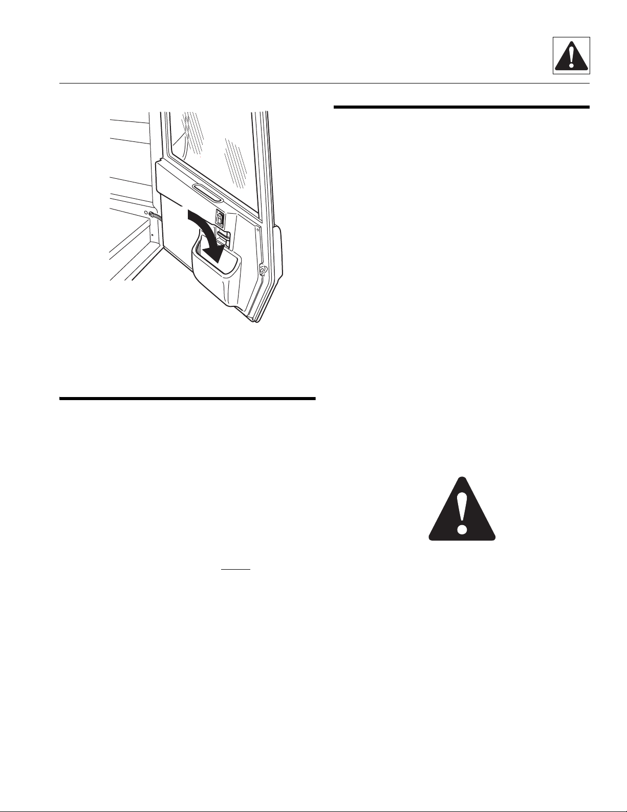
1.2 OWNERS/OPERATORS MANUAL
The vehicle must be driven and operated as a consequence of, or when performing, service, maintenance
and test procedures. The service technician must, therefore, thoroughly read, understand and follow the Sky Trak
MMV Telescopic Material Handler Owners/Operators
Manual.
An Owners/Operators and EMI Safety Manuals are supplied with each vehicle and must be kept in the pocket (1)
located in the lower door in the cab.
In the event that the Owners/Operators or Safety Manuals are missing, consult the local JLG Authorized Service
Center (ASC) or the JLG Service Department before proceeding.
1.2
Model MMV Rev. 12/04
Page 11
1
MM2240
1.3 TRAINING MECHANICS AS
OPERATORS
Because it is necessary to move the vehicle to service or
maintain the vehicle, it is necessary that all mechanics
are OSHA trained and certified as operators. A
mechanic trained in the proper operation of the vehicle
can better determine whether all the functions are
operating correctly.
Safety Practices
1.4 SAFETY INFORMATION
The following information provides general safety instructions, including examples of hazard statements with signal words, notification of hazards, methods to help avoid
hazards and the consequences of failing to follow the
safety information. To avoid possible death or injury,
carefully read and follow all safety messages. Fully understand the potential causes of death or injury.
In the event of an accident, know where to obtain medical
assistance, use a first-aid kit and fire extinguisher/fire
suppression system. Keep emergency telephone numbers (fire department, ambulance, rescue squad/paramedics, police department, etc.) nearby. If working alone,
check with another person routinely to help ensure personal safety.
The information in this manual does not replace any other
safety rules or proper judgment. Governmental
authorities and employers also have their own sets of
rules, codes, regulations and laws. Before starting work
at a worksite, check with the supervisor or safety
coordinator and ask about the safety policy. Learn the
safety requirements in effect before operating,
maintaining, servicing or testing the vehicle. Safety
depends on following safety requirements.
1.4.1 Safety Alert Symbol
The exclamation mark within a triangle is the Safety Alert
Symbol.
At the time of original purchase, the purchaser of this
vehicle was instructed by the seller on its proper use.
When this vehicle is to be serviced or maintained by
someone other than the purchaser, make certain that the
mechanic is trained, in accordance with the OSHA
regulations listed in the NOTICE below, and reads and
understands the Sky Trak MMV Telescopic Material
Handler Owners/Operators Manual before
operating or
maintaining the vehicle.
NOTICE: Under OSHA rules, it is the responsibility of the
employer to provide operator training. Successful completion and certification of Safety Training for Rough Terrain Forklifts is required. Operator Training Kits are
available by calling Ken Cook Company at
(414) 466-6060. An order form for these kits is available
through our website, http://www.jlg.com.
In addition, make sure that the mechanic has completed
a walk-around inspection of the vehicle, is familiar with
all decals and/or decal plates on the vehicle, and has
demonstrated the correct use of all controls.
Model MMV Rev. 12/04
OP0330
This symbol means “Attention! Become Alert! Your
Safety Is Involved!” The symbol is used to attract attention to safety hazards found on the vehicle safety decals
and/or decal plates throughout this manual.
1.3
Page 12
Safety Practices
1.4.2 Hazard Statements
Signal words and messages are used in conjunction with
the safety alert symbol to create hazard statements.
These hazard statements convey important information
about safety.
Four types of hazard statements are used in this manual.
Each statement indicates the existence and degree of relative risk of the hazard described within the statement
that follows the signal word.
Explanations of the types of hazard statements are as
follows:
DANGER:
The signal word “DANGER” indicates an imminently
hazardous situation which, if not avoided, will result in
death or serious injury.
WARNING:
The signal word “WARNING” indicates a potentially hazardous situation which, if not avoided, could result in
death or serious injury.
CAUTION:
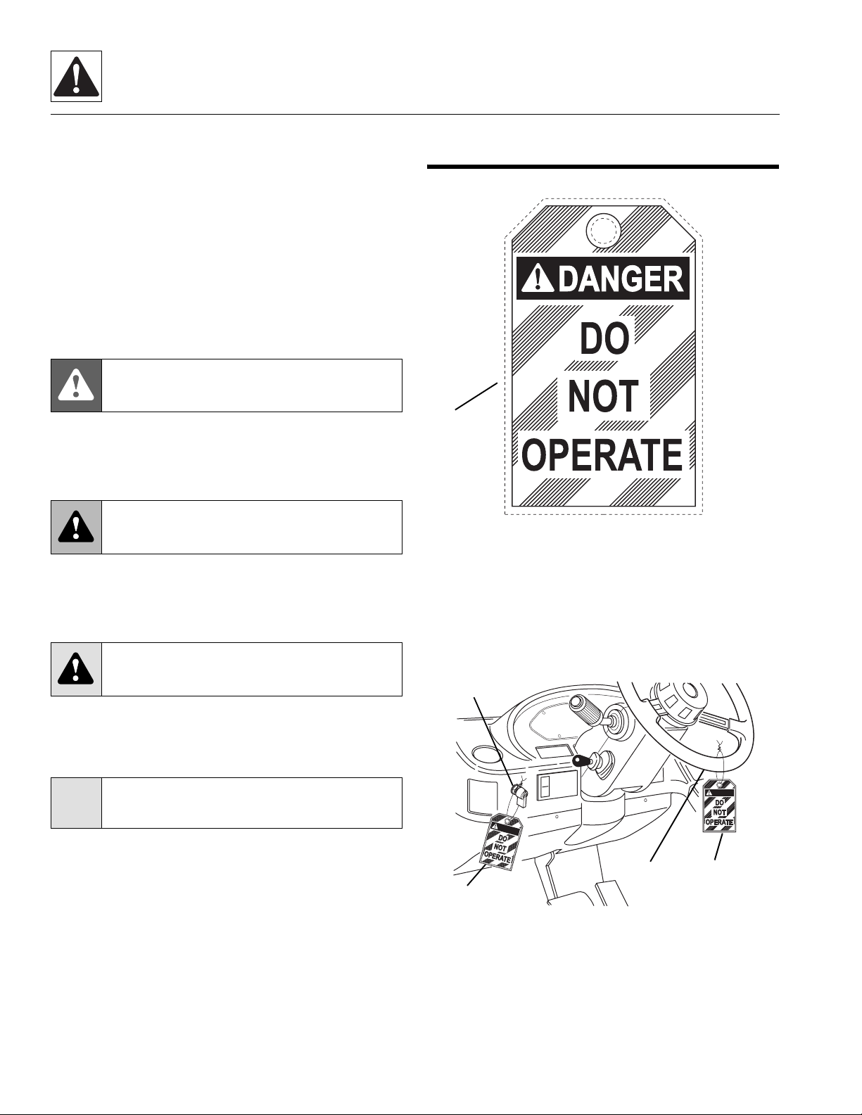
1.5 ACCIDENT PREVENTION
TAG U SAGE
1
MC0690
Before beginning any maintenance or service, place an
Accident Prevention Tag (1) on both the ignition switch
(2) and steering wheel (3), stating that the vehicle should
not be operated. Actual Accident Prevention Tags, that
can be punched out and used, are included as the last
page in this manual. Retain these Accident Prevention
Tags for reuse at a later date.
The signal word “CAUTION” indicates a potentially hazardous situation which, if not avoided, could result in minor or moderate injury.
CAUTION:
The signal word “CAUTION,” used without the safety
alert symbol, indicates a potentially hazardous situation
which, if not avoided, could result in property damage.
For safe maintenance of the vehicle, read, understand
and follow all DANGER, WARNING and CAUTION
information.
1.4
2
DANGER
D
A
N
G
E
R
3
1
1
OM1510
Model MMV Rev. 12/04
Page 13

Safety Practices
1.6 SAFETY INSTRUCTIONS
Following are general safety statements to consider
before
Additional statements related to specific tasks and procedures are located throughout this manual and are listed
prior to any work instructions to provide safety information before the hazard occurs.
For all safety messages, carefully read, understand and
follow the instructions
1.6.1 Personal Hazards
HAIR and CLOTHING: DO NOT wear loose clothing or
jewelry. Tie up or restrain hair. Wear the correct safety
equipment for the job (including but not limited to: hard
hat; safety shoes; safety glasses, goggles, or face shield;
heavy gloves; hearing protection; reflective clothing; wetweather gear; respirator or filter mask).
E
tection when chiseling, grinding, sanding, welding, painting, repairing hydraulic systems, or checking, testing or
charging the battery.
B
tion when grinding or painting.
H
tion in a high-noise area.
F
inforced toe caps and slip-resistant soles.
L
least one assistant or a suitable sling and hoist.
performing maintenance procedures on a vehicle.
before
YE PROTECTION: Always wear appropriate eye pro-
REATHING PROTECTION: Wear respiratory protec-
EARING PROTECTION: Always wear hearing protec-
OOT PROTECTION: Wear protective footwear with re-
IFTING: NEVER lift a heavy object without the help of at
proceeding.
1.6.2 Equipment Hazards
OWNERS/OPERATORS MANUAL: Before operating
the vehicle, carefully read, understand and follow the
Owners/Operators Manual.
O
PERATIONAL PROTECTION: Before operating the vehicle or returning it for operational use, check that the operator’s protective structure is intact, undamaged,
unmodified and secure.
L
IFTING OF EQUIPMENT: Before using any lifting equipment (chains, slings, brackets, hooks, etc.), verify that it
is of the proper capacity, in good working condition and
properly attached.
NEVER stand or otherwise become positioned under a
suspended load or under raised equipment. The load or
equipment could fall or tip.
DO NOT use a hoist or jack to support raised equipment.
A hoist or jack failure can allow the equipment to fall or tip.
Always support equipment with proper capacity blocks or
stands that are properly rated for the load.
C
OMPRESSED AIR: Before and during the use of compressed air, wear eye protection and advise other personnel in the work area that compressed air is about to be
used.
H
AND TOOLS: Always use the proper tool for the job;
keep tools clean and in good working order, and use special service tools only as recommended.
Model MMV Rev. 12/04
1.5
Page 14
Safety Practices
1.6.3 General Hazards
SOLVENTS: Only use approved solvents, and solvents
that are known to be safe for use.
OUSEKEEPING: Keep the work area and operator’s
H
cab clean and remove all hazards (debris, oil, tools, etc.).
F
IRST AID: Immediately clean, dress and report all injuries (cuts, abrasions, burns, etc.), no matter how minor.
Know the location of a first-aid kit, and know how to
use it.
C
LEANLINESS: Wear eye protection, and clean all components with a high-pressure or steam cleaner before attempting service.
When removing hydraulic components, plug hose ends
and connections to prevent excess leakage and contamination. Place a suitable catch basin beneath the vehicle
to capture fluid run-off.
1.6.4 Operational Hazards
OPERATIONAL CONSIDERATIONS: Before operating
the vehicle, carefully read, understand and follow the
Owners/Operators Manual.
E
NGINE: Stop the engine before performing any service.
ANGEROUS START: Place Accident Prevention Tags
D
on both the ignition switch and steering wheel before attempting to perform any service or maintenance. Disconnect battery leads. Place a warning sign on vehicles that
are dangerous to start, if leaving the vehicle unattended.
V
ENTILATION: Avoid prolonged engine operation in en-
closed areas without adequate ventilation.
R
ADIATOR CAP: Always wear steam-resistant, heatprotective gloves when opening the radiator cap. Cover
cap with a clean, thick cloth and turn slowly to the first
stop to relieve pressure.
SOFT SURFACES AND SLOPES
vehicle that is parked on a soft surface or slope (inclined
ground or hill). The vehicle must be on a hard, level
surface with the wheels blocked when performing any
service. Obtain assistance, block all wheels, and add
supports if necessary before beginning any work.
S
UPPORTS AND STRAPS: Install safe, stable supports,
slings or straps, beneath or around a component or structural member before beginning any work.
: NEVER work on a
F
LUID PRESSURE: Before loosening any hydraulic or
diesel fuel component, hose or tube, turn engine OFF.
Wear heavy, protective gloves and eye protection.
NEVER check for leaks using any part of your body; use
a piece of cardboard or wood instead. If injured, seek
medical attention immediately. Diesel fuel leaking under
pressure can explode. Hydraulic fluid and diesel fuel
leaking under pressure can penetrate the skin, causing
infection, gangrene, and other serious personal injury.
Relieve all pressure before disconnecting any component, part, line or hose. Slowly loosen parts and allow release of residual pressure before removing any part or
component. Before starting engine or applying pressure,
use components, parts, hoses and pipes that are in good
condition, connected properly, and tightened to the proper torque. Capture fluid in an appropriate container and
dispose of it in accordance with prevailing environmental
regulations.
P
RESSURE TESTING: When conducting any test, only
use test equipment that is correctly calibrated and in good
condition. Use the correct equipment in the proper manner, and make changes or repairs as indicated by the test
procedures to achieve the desired results.
L
EAVING VEHICLE: Lower the attachment to the ground
before leaving the vehicle.
T
IRE PRESSURE: Always keep tires inflated to the proper pressure to help prevent dangerous travel and loadhandling situations. DO NOT over-inflate tires.
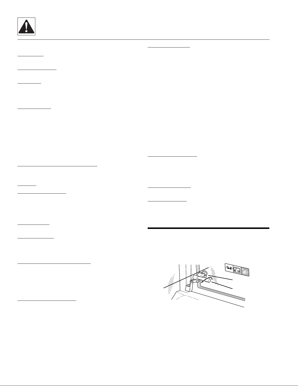
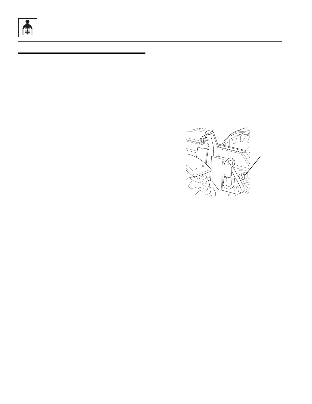
1.7 EMERGENCY EXIT REAR WINDOW
The rear window in the enclosed cab can be used as an
emergency exit by removing the latch pins (1) located on
the two window latches (2). Once the latch pins have
been removed, the window (3) can be swung open.
1
.
2
.
3
.
4
1
0
9
7
9
1
1
3
2
OT08902
1.6
Model MMV Rev. 12/04
Page 15
Safety Practices
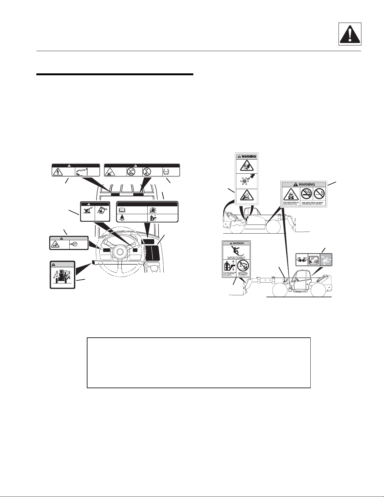
1.8 HAZARD/EMERGENCY
INFORMATION SIGNS
Locations of vehicle hazard and other emergency information signs are shown below. As part of routine maintenance, check that ALL hazard and emergency
information signs on the vehicle are present and readable. Keep all signs clean.
CONTACTING
ELECTRIC
POWER LINES
can result in
electrocution.
6
9
5
WARNING
VEHICLE
ROLLAWAY
can cause
death or
serious
injury.
WARNING
DANGER
ALWAYS
engage
parking
brake
before
dismounting.
NEVER operate
vehicle within
10 feet (3m) of
electric power
lines.
AVOID CRUSHING
if vehicle tips.
Jumping can
result in death or
serious injury.
DANGER
DO NOT JUMP.
Brace yourself.
Stay in cab.
Keep seat belt on.
VEHICLE
TIPOVER
can result
in death or
serious injury.
DANGER
DO NOT raise
DO NOT
boom while
travel
on a slope
with the
unless load
boom
is level.
raised.
SAFETY INSTRUCTIONS
1. Read operators manual
before operating.
2. Fasten seat belt.
MAINTAIN
proper tire
pressure at
all times.
8
10
3. Allow no riders.
4. Use an approved work
platform to lift or lower
personnel.
7
If a replacement sign is needed, refer to the Owners/Operators Manual and parts catalog for the latest parts numbers and ordering information. Or, contact JLG Inc.
directly at:
Domestic: 1-877-554-5438
or
International: 1-717-485-5161
MOVING PARTS can cut.
11
Keep clear of fan and belts
while engine is running.
MOVING PARTS can entangle.
14
2.
1.
12
15
3.
4109791
Allow no riders.
A
4
4. No Riders WARNING
5. Vehicle Rollaway WARNING
6. Electrocution DANGER
7. Load Chart Booklet
8. Tipover DANGER - Operating
9. Do Not Jump DANGER
OT05602
13
10. Safety Instructions
11. Moving Parts WARNING
12. Explosive Gases WARNING
13. Carrying Personnel WARNING
14. Boom Angle Indicator
15. Emergency Exit (Enclosed Cab Only)
B
Note: Many of these hazard related signs are available free of charge by
calling JLG Inc. at 1-717-485-5161(Domestic) or 1-877-554-5438(International).
OM11412
Model MMV Rev. 12/04
1.7
Page 16

Safety Practices
This Page Intentionally Left Blank
1.8
Model MMV Rev. 12/04
Page 17

Section 2
General Information, Specifications and Maintenance
Contents
PARAGRAPH TITLE PAGE
2.1 MMV Component Terminology. . . . . . . . . . . . . . . . . . . . . . . . . . . . . . . . . . . . . . . . 2.5
2.2 Introduction . . . . . . . . . . . . . . . . . . . . . . . . . . . . . . . . . . . . . . . . . . . . . . . . . . . . . . . 2.6
2.2.1 Service Methods . . . . . . . . . . . . . . . . . . . . . . . . . . . . . . . . . . . . . . . . . . . . 2.6
2.2.2 The Owners/Operators Manual . . . . . . . . . . . . . . . . . . . . . . . . . . . . . . . . . 2.6
2.2.3 Replacement Parts and Warranty Information . . . . . . . . . . . . . . . . . . . . . 2.6
2.2.4 Disclaimer . . . . . . . . . . . . . . . . . . . . . . . . . . . . . . . . . . . . . . . . . . . . . . . . . 2.6
2.3 Torques . . . . . . . . . . . . . . . . . . . . . . . . . . . . . . . . . . . . . . . . . . . . . . . . . . . . . . . . . . 2.7
2.3.1 Fasteners . . . . . . . . . . . . . . . . . . . . . . . . . . . . . . . . . . . . . . . . . . . . . . . . . 2.7
2.3.2 Bolts and Nuts. . . . . . . . . . . . . . . . . . . . . . . . . . . . . . . . . . . . . . . . . . . . . . 2.7
2.3.3 Straight Thread O-ring Fitting (Non-Adjustable) . . . . . . . . . . . . . . . . . . . . 2.7
2.3.4 Straight Thread O-ring Fitting (Adjustable) . . . . . . . . . . . . . . . . . . . . . . . . 2.7
2.3.5 Flat-Face O-ring Fittings . . . . . . . . . . . . . . . . . . . . . . . . . . . . . . . . . . . . . . 2.8
2.4 Metric Conversion Factors . . . . . . . . . . . . . . . . . . . . . . . . . . . . . . . . . . . . . . . . . . . 2.8
2.4.1 Approximate American to Metric Conversions . . . . . . . . . . . . . . . . . . . . . 2.8
2.4.2 Approximate Metric to American Conversions . . . . . . . . . . . . . . . . . . . . . 2.9
2.5 Specifications . . . . . . . . . . . . . . . . . . . . . . . . . . . . . . . . . . . . . . . . . . . . . . . . . . . . . 2.10
2.5.1 Vehicle Dimensions . . . . . . . . . . . . . . . . . . . . . . . . . . . . . . . . . . . . . . . . . . 2.10
2.5.2 Vehicle Weights. . . . . . . . . . . . . . . . . . . . . . . . . . . . . . . . . . . . . . . . . . . . . 2.12
2.5.3 Attachment Weights . . . . . . . . . . . . . . . . . . . . . . . . . . . . . . . . . . . . . . . . . 2.12
2.5.4 Performance Specifications. . . . . . . . . . . . . . . . . . . . . . . . . . . . . . . . . . . . 2.12
2.5.5 Hydraulic Cylinder Performance Specifications . . . . . . . . . . . . . . . . . . . . 2.13
2.5.6 Electrical System . . . . . . . . . . . . . . . . . . . . . . . . . . . . . . . . . . . . . . . . . . . 2.14
2.5.7 Engine Performance Specifications . . . . . . . . . . . . . . . . . . . . . . . . . . . . . 2.15
2.5.8 Fluid and Lubricant Capacities . . . . . . . . . . . . . . . . . . . . . . . . . . . . . . . . . 2.16
2.5.9 Hydraulic System . . . . . . . . . . . . . . . . . . . . . . . . . . . . . . . . . . . . . . . . . . . 2.17
2.5.10 Tires . . . . . . . . . . . . . . . . . . . . . . . . . . . . . . . . . . . . . . . . . . . . . . . . . . . . . 2.18
2.5.11 Miscellaneous Specifications . . . . . . . . . . . . . . . . . . . . . . . . . . . . . . . . . . 2.18
2.5.12 Tamper Proofing . . . . . . . . . . . . . . . . . . . . . . . . . . . . . . . . . . . . . . . . . . . . 2.19
2.5.13 Fork Ratings . . . . . . . . . . . . . . . . . . . . . . . . . . . . . . . . . . . . . . . . . . . . . . . 2.19
Model MMV Rev. 12/04
2.1
Page 18

General Information, Specifications and Maintenance
2.6 Fluids, Lubricants and Capacities . . . . . . . . . . . . . . . . . . . . . . . . . . . . . . . . . . . . . 2.20
2.6.1 Axles (Differential Housings) and Transfer Case. . . . . . . . . . . . . . . . . . . . 2.20
2.6.2 Wheel Ends. . . . . . . . . . . . . . . . . . . . . . . . . . . . . . . . . . . . . . . . . . . . . . . . 2.20
2.6.3 Lubrication Points (Grease Fittings) . . . . . . . . . . . . . . . . . . . . . . . . . . . . . 2.21
2.6.4 Hydraulic System . . . . . . . . . . . . . . . . . . . . . . . . . . . . . . . . . . . . . . . . . . . 2.21
2.6.5 Engine . . . . . . . . . . . . . . . . . . . . . . . . . . . . . . . . . . . . . . . . . . . . . . . . . . . . 2.21
2.6.6 Transmission . . . . . . . . . . . . . . . . . . . . . . . . . . . . . . . . . . . . . . . . . . . . . . . 2.22
2.6.7 Air Conditioning . . . . . . . . . . . . . . . . . . . . . . . . . . . . . . . . . . . . . . . . . . . . . 2.22
2.6.8 Drive Shaft Splines . . . . . . . . . . . . . . . . . . . . . . . . . . . . . . . . . . . . . . . . . . 2.22
2.6.9 General Anti-Corrosion . . . . . . . . . . . . . . . . . . . . . . . . . . . . . . . . . . . . . . . 2.23
2.6.10 Carriage Fork Shafts and Wear Pads . . . . . . . . . . . . . . . . . . . . . . . . . . . . 2.23
2.6.11 Paint . . . . . . . . . . . . . . . . . . . . . . . . . . . . . . . . . . . . . . . . . . . . . . . . . . . . . 2.23
2.6.12 Thread Locking Compound . . . . . . . . . . . . . . . . . . . . . . . . . . . . . . . . . . . . 2.23
2.7 Cleaning . . . . . . . . . . . . . . . . . . . . . . . . . . . . . . . . . . . . . . . . . . . . . . . . . . . . . . . . . . 2.24
2.8 Replacement . . . . . . . . . . . . . . . . . . . . . . . . . . . . . . . . . . . . . . . . . . . . . . . . . . . . . . 2.24
2.9 Hoses and Tubes . . . . . . . . . . . . . . . . . . . . . . . . . . . . . . . . . . . . . . . . . . . . . . . . . . . 2.24
2.9.1 Hose and Tube Inspection. . . . . . . . . . . . . . . . . . . . . . . . . . . . . . . . . . . . . 2.24
2.9.2 Hose and Tube Installation . . . . . . . . . . . . . . . . . . . . . . . . . . . . . . . . . . . . 2.24
2.10 Bearings . . . . . . . . . . . . . . . . . . . . . . . . . . . . . . . . . . . . . . . . . . . . . . . . . . . . . . . . . . 2.25
2.10.1 Bearing Removal. . . . . . . . . . . . . . . . . . . . . . . . . . . . . . . . . . . . . . . . . . . . 2.25
2.10.2 Bearing Cleaning. . . . . . . . . . . . . . . . . . . . . . . . . . . . . . . . . . . . . . . . . . . . 2.25
2.10.3 Bearing Installation . . . . . . . . . . . . . . . . . . . . . . . . . . . . . . . . . . . . . . . . . . 2.25
2.11 Pressure Testing and Adjustment . . . . . . . . . . . . . . . . . . . . . . . . . . . . . . . . . . . . . 2.25
2.12 After Service Startup and Checks . . . . . . . . . . . . . . . . . . . . . . . . . . . . . . . . . . . . . 2.25
2.12.1 After Service Startup. . . . . . . . . . . . . . . . . . . . . . . . . . . . . . . . . . . . . . . . . 2.25
2.12.2 After Electrical/Electronic Component Service . . . . . . . . . . . . . . . . . . . . . 2.26
2.12.3 After Hydraulic Component Service . . . . . . . . . . . . . . . . . . . . . . . . . . . . . 2.26
2.12.4 After Brake System Service . . . . . . . . . . . . . . . . . . . . . . . . . . . . . . . . . . . 2.26
2.12.5 After Fuel System Service. . . . . . . . . . . . . . . . . . . . . . . . . . . . . . . . . . . . . 2.26
2.12.6 After Transmission Service or Replacement . . . . . . . . . . . . . . . . . . . . . . . 2.26
2.12.7 After Tire and Wheel Service . . . . . . . . . . . . . . . . . . . . . . . . . . . . . . . . . . 2.27
2.12.8 After Engine Service . . . . . . . . . . . . . . . . . . . . . . . . . . . . . . . . . . . . . . . . . 2.27
2.12.9 After Boom Service . . . . . . . . . . . . . . . . . . . . . . . . . . . . . . . . . . . . . . . . . . 2.27
2.12.10 After Axle Service . . . . . . . . . . . . . . . . . . . . . . . . . . . . . . . . . . . . . . . . . . . 2.27
2.2
Model MMV Rev. 12/04
Page 19

General Information, Specifications and Maintenance
2.13 Maintenance Instructions . . . . . . . . . . . . . . . . . . . . . . . . . . . . . . . . . . . . . . . . . . . . 2.28
2.13.1 Maintenance Schedule and Checklist . . . . . . . . . . . . . . . . . . . . . . . . . . . . 2.28
2.13.2 Air Cleaner . . . . . . . . . . . . . . . . . . . . . . . . . . . . . . . . . . . . . . . . . . . . . . . . 2.30
2.13.3 Closed Cab Air Filters . . . . . . . . . . . . . . . . . . . . . . . . . . . . . . . . . . . . . . . . 2.32
2.13.4 Engine Cooling System. . . . . . . . . . . . . . . . . . . . . . . . . . . . . . . . . . . . . . . 2.33
2.13.5 Engine Oil and Filter . . . . . . . . . . . . . . . . . . . . . . . . . . . . . . . . . . . . . . . . . 2.35
2.13.6 Engine Oil Sample Point . . . . . . . . . . . . . . . . . . . . . . . . . . . . . . . . . . . . . . 2.37
2.13.7 Engine Fuel System . . . . . . . . . . . . . . . . . . . . . . . . . . . . . . . . . . . . . . . . . 2.37
2.13.8 Engine Fan Belt & Air Conditioner Compressor Belt. . . . . . . . . . . . . . . . . 2.40
2.13.9 Hydraulic System Oil and Filter. . . . . . . . . . . . . . . . . . . . . . . . . . . . . . . . . 2.41
2.13.10 Transmission Oil and Filter . . . . . . . . . . . . . . . . . . . . . . . . . . . . . . . . . . . . 2.43
2.13.11 Axle Oil . . . . . . . . . . . . . . . . . . . . . . . . . . . . . . . . . . . . . . . . . . . . . . . . . . . 2.45
2.13.12 Brake Disc Wear Check . . . . . . . . . . . . . . . . . . . . . . . . . . . . . . . . . . . . . . 2.46
2.13.13 Wheel End Oil . . . . . . . . . . . . . . . . . . . . . . . . . . . . . . . . . . . . . . . . . . . . . . 2.48
2.13.14 Transfer Case Oil . . . . . . . . . . . . . . . . . . . . . . . . . . . . . . . . . . . . . . . . . . . 2.49
2.13.15 Wheels and Tires . . . . . . . . . . . . . . . . . . . . . . . . . . . . . . . . . . . . . . . . . . . 2.50
2.13.16 Emergency Tire Inflation System . . . . . . . . . . . . . . . . . . . . . . . . . . . . . . . 2.50
2.13.17 Batteries . . . . . . . . . . . . . . . . . . . . . . . . . . . . . . . . . . . . . . . . . . . . . . . . . . 2.54
2.13.18 Fuse and Relay Replacement . . . . . . . . . . . . . . . . . . . . . . . . . . . . . . . . . . 2.56
2.13.19 Boom Wear Pad Maintenance . . . . . . . . . . . . . . . . . . . . . . . . . . . . . . . . . 2.60
2.13.20 Boom Chain Inspection . . . . . . . . . . . . . . . . . . . . . . . . . . . . . . . . . . . . . . . 2.61
2.13.21 Boom Chain Tension & Adjustment. . . . . . . . . . . . . . . . . . . . . . . . . . . . . . 2.64
2.13.22 Chain Lubrication . . . . . . . . . . . . . . . . . . . . . . . . . . . . . . . . . . . . . . . . . . . 2.67
2.13.23 Short Term Storage. . . . . . . . . . . . . . . . . . . . . . . . . . . . . . . . . . . . . . . . . . 2.68
2.13.24 Long Term Storage . . . . . . . . . . . . . . . . . . . . . . . . . . . . . . . . . . . . . . . . . . 2.68
2.13.25 Counterweight Removal and Reassembly . . . . . . . . . . . . . . . . . . . . . . . . 2.70
2.13.26 Transport . . . . . . . . . . . . . . . . . . . . . . . . . . . . . . . . . . . . . . . . . . . . . . . . . . 2.72
2.14 Emergency Operations . . . . . . . . . . . . . . . . . . . . . . . . . . . . . . . . . . . . . . . . . . . . . . 2.77
2.14.1 Towing a Disabled Vehicle Short Distances . . . . . . . . . . . . . . . . . . . . . . . 2.77
2.14.2 Towing a Disabled Vehicle Long Distances . . . . . . . . . . . . . . . . . . . . . . . . 2.78
2.14.3 Boom Lowering and Retracting . . . . . . . . . . . . . . . . . . . . . . . . . . . . . . . . . 2.80
2.15 Parking Brake/Transmission De-Clutch Test Procedures . . . . . . . . . . . . . . . . . . 2.81
Model MMV Rev. 12/04
2.3
Page 20

General Information, Specifications and Maintenance
This Page Intentionally Left Blank
2.4
Model MMV Rev. 12/04
Page 21
General Information, Specifications and Maintenance
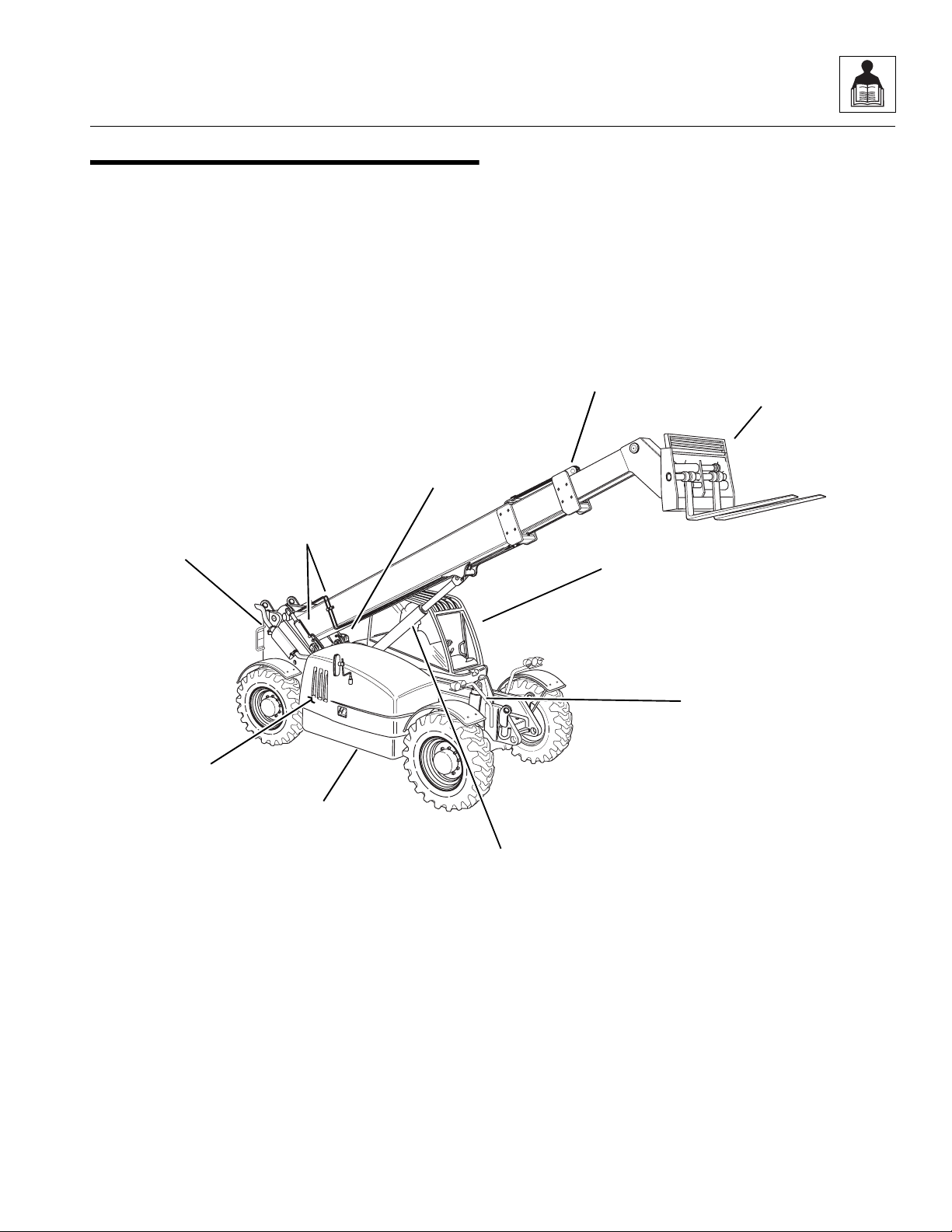
2.1 MMV COMPONENT TERMINOLOGY
To understand the safety, operation and maintenance
information presented in this manual, it is necessary that
the operator/mechanic be familiar with the name and
location of the major assemblies on this vehicle. The
following illustration identifies the components that are
referred to throughout this manual.
Stabilizer
Cylinder
Slave
Cylinders (2)
Rear Door
(Not Visible)
(1 Not Visible)
Boom
Assembly
Operator’s
Protective
Structure
Carriage
Assembly
Engine
Compartment
Frame Sway
Cylinder
Hydraulic
Oil Tank
Lift/Lower
Cylinder
MM1731
Model MMV Rev. 12/04
2.5
Page 22
General Information, Specifications and Maintenance
2.2 INTRODUCTION
2.2.1 Service Methods
Appropriate service methods and proper repair procedures are essential for safe, reliable operation of this vehicle and the safety of the individual doing the work. This
Service Manual provides general direction for accomplishing service and repair work with tested, effective
techniques. Following them will assure reliability.
There are many variations in procedures, techniques,
tools, and parts for servicing vehicles, as well as work
skills. This Manual cannot possibly anticipate all such
variations and provide advice or cautions for each one.
Accordingly, anyone who intends to depart from the instructions in this Manual must first consider personal
safety and then vehicle integrity.
IMPORTANT: JLG recommends the use of environmentally sound waste storage and disposal practices.
NEVER drain fluids on the ground or into a sewer or
catch basin. Use suitable collection containers, then
store and/or dispose of waste products in an approved
and safe manner. Check and obey all Federal, State and/
or Local regulations regarding waste storage, disposal
and recycling.
2.2.3 Replacement Parts and Warranty
Information
For reference when ordering replacement parts or making
service inquiries about the vehicle, the vehicle serial
number is required to help assure the provision of correct
parts and information. Before ordering parts or initiating
service inquiries, make note of the serial number.
The vehicle serial number plate (1) is located on the front
of the main frame.
1
2.2.2 The Owners/Operators Manual
The Owners/Operators Manual provides information you
need to properly operate and maintain this vehicle.
IMPORTANT: Before you operate this vehicle, read the
manual completely and carefully, so that you will understand the safety instructions and the operation of the
controls and safety equipment. You must comply with all
Danger, Warning, and Caution notices. They are for your
benefit.
All references to the right side, left side, front, and rear
are given from the operator’s seat looking in a forward
direction.
OM1370
IMPORTANT: The replacement of any part on this vehicle with any other than a JLG authorized replacement
part can adversely affect the performance, durability, or
safety of the vehicle, and will void the warranty. JLG disclaims liability for any claims or damages, whether
regarding property damage, personal injury or death
arising out of the use of unauthorized replacement parts.
A warranty registration form must be filled out by the JLG
Authorized Service Center (ASC), signed by the
purchaser, and returned to JLG when the vehicle is sold
and/or put into use.
Registration activates the warranty period and helps to
assure that warranty claims are promptly processed. To
guarantee full warranty service, verify that the distributor
has returned the business reply card of the warranty registration form to JLG.
2.2.4 Disclaimer
JLG reserves the right to make changes to and to add im-
provements upon its product at any time, without public
notice or obligation. JLG also reserves the right to discontinue manufacturing any product at its discretion at
any time.
2.6
Model MMV Rev. 12/04
Page 23
General Information, Specifications and Maintenance
2.3 TORQUES
2.3.1 Fasteners
All fasteners (nuts, bolts, washers, etc.) are equal to SAE
Grade 5 (PC8.8) and are plated, unless otherwise specified.
2.3.2 Bolts and Nuts
Unless otherwise specified, the following values apply for
Grade 5 (PC8.8) nuts and bolts:
Size Torque Size Torque
Inch lb/ft Nm mm Nm lb/ft
1/4 9 12 6.0 10 7
5/16 17 24 8.0 25 18
3/8 31 42 10.0 50 37
7/16 50 68 -- -- --
1/2 75 102 12.0 80 59
9/16 110 150 14.0 130 95
5/8 150 203 16.0 200 146
3/4 250 340 20.0 360 263
7/8 380 515 22.0 510 372
1.0 585 793 24.0 650 475
2.3.3 Straight Thread O-ring Fitting
(Non-Adjustable)
When the vehicle leaves the factory, it is equipped only
with straight thread o-ring fittings. Customer-added accessories may differ; therefore, consult the manufacturer’s product literature for information.
1. Verify that both threads and sealing surfaces are
free of burrs, nicks, scratches, and any foreign
material.
2. Lubricate the new o-ring with a light coating of
hydraulic oil.
3. Tighten fitting to the proper torque according to the
following chart:
SAE
Size
4
6
8
10
12
16
20
24
15-17
34-36
58-62
100-110
134-146
202-218
248-272
303-327
Torque
lb/ft Nm
20-23
46-49
79-84
136-149
181-198
274-296
336-369
411-443
2.3.4 Straight Thread O-ring Fitting
(Adjustable)
When the vehicle leaves the factory, it is equipped only
with straight thread o-ring fittings. Customer-added accessories may differ; therefore, consult the manufacturer’s product literature for information.
1. Verify that both mating parts are free of burrs, nicks,
scratches, and any foreign material.
2. Lubricate the new o-ring with a light coat of hydraulic
oil.
3. Back off the locknut as far as possible.
4. Screw the fitting into the port by hand until the backup washer contacts the face of the port and is
pushed all the way towards the locknut.
5. To position the fitting, unscrew by the required
amount, but not more than one full turn.
6. Hold the fitting in the desired position and tighten to
the proper torque according to the following chart:
Adjustable Straight-Thread O-ring
Fitting Torque Chart
SAE
Size
4
6
8
10
12
16
20
24
15-17
34-36
58-62
100-110
134-146
202-218
248-272
303-327
Torque
lb/ft Nm
20-23
46-49
79-84
136-149
181-198
274-296
336-369
411-443
Model MMV Rev. 12/04
2.7
Page 24

General Information, Specifications and Maintenance
2.3.5 Flat-Face O-ring Fittings
When the vehicle leaves the factory, it is equipped only
with straight thread o-ring fittings. Customer-added
accessories may differ; therefore, consult the manufacturer’s product literature for information.
Improper assembly of this type of joint will result in a leaking
joint. Under tightening will result in the joint loosening during normal use. Foreign material on either sealing surfaces
will cause damage to one or both mating parts when the
joint is tightened, resulting in a leaking joint. The absence
of the fitting o-ring will cause the joint to leak.
1. Verify that both threads and sealing surfaces are
free of burrs, nicks, scratches, and any foreign
material.
2. Inspect the male fitting for the presence of the o-ring
seal. Replace the o-ring if missing or damaged.
3. Place the flat surface of the female connector in full
contact with the o-ring in the male connector.
4. Finger tighten the nut onto the fitting.
5. Hold the fitting in the desired position, for hoses and
swivel fittings, use a second wrench to keep the
female connector from moving during tightening.
Tighten to the proper torque according to the
following chart:
SAE
Size
4
6
8
10
12
16
20
24
19-36
28-54
42-80
65-126
100-180
130-240
150-280
175-330
Torque
lb/ft Nm
26-49
38-73
57-108
88-171
136-244
176-325
203-380
237-447
2.4 METRIC CONVERSION FACTORS
2.4.1 Approximate American to Metric
Conversions
When this is known Multiply by To Find
TORQUE (moment of force)
Pound/feet (lb/ft) 1.356 Newton meters (Nm)
Pound/inches (lb/in) 0.113 Newton meters (Nm)
POWER
Horsepower (hp) 745.7 Watts
SPEED (velocity)
Miles per hour (mph) 1.609 Kilometers per hour
(km/hr; kph)
LENGTH (distance)
Inches (in) 25.4 Millimeters (mm)
Inches (in) 2.5 Centimeters (cm)
Feet (ft) 30.5 Centimeters (cm)
Feet (ft) 0.305 Meters (m)
Yards (yd) 0.9 Meters (m)
Miles (mi) 1.6 Kilometers (km)
AREA
2
Square inches (in
Square feet (ft
Square yards (yd
Square miles (mi
Acres 0.4 Hectares (ha)
MASS (weight)
Ounces (oz) 28.3 Grams (g)
Pounds (lb) 0.4536 Kilograms (kg)
Short tons (2000 lb) 0.9 Metric ton (t)
) 6.5 Square centimeters (cm2)
2
) 0.09 Square meters (m2)
2
) 0.8 Square meters (m2)
2
) 2.6 Square kilometers (km2)
2.8
Model MMV Rev. 12/04
Page 25

General Information, Specifications and Maintenance
VOLUME
Teaspoons (tsp) 5 Milliliters (ml)
Tablespoons (Tbsp) 15 Milliliters (ml)
3
Cubic inches (in
) 16 Milliliters (ml)
Fluid ounces (fl oz) 30 Milliliters (ml)
Cups (c) 0.24 Liters
Pints (pt) 0.47 Liters
Quarts (qt) 0.95 Liters
Gallons (gal) 3.8 Liters
3
Cubic feet (ft
Cubic yards (yd
) 0.03 Cubic meters (m3)
3
) 0.76 Cubic meters (m3)
AIR PRESSURE
Pounds per
square inch (psi) 6.895 Kilopascals (kPa)
HYDRAULIC PRESSURE
Pounds per
square inch (psi) 0.069 Bar
TEMPERATURE (exact)
To determine degrees Celsius (° C), subtract 32, then
multiply by 0.56; (° F -32) x 0.56 = ° C.
2.4.2 Approximate Metric to American
Conversions
When this is known Multiply by To Find
TORQUE (moment of force)
Newton meters (Nm) 0,738 Pounds/feet (lb/ft)
Newton meters (Nm) 8,85 Pounds/inches (lb/in)
POWER
Watts 0,0013 Horsepower (hp)
SPEED (velocity)
Kilometers per
hour (km/hr; kph) 0,621 Miles per hour (mph)
LENGTH (distance)
Millimeters (mm) 0,0394 Inches (in)
Centimeters (cm) 0,394 Inches (in)
Meters (m) 3,281 Feet (ft)
Meters (m) 1,1 Yards (yd)
Kilometers (km) 0,621 Miles (mi)
AREA
Square centimeters
2
) 0,4 Square inches (in2)
(cm
Square meters (m
2
) 1,1 Square yards (yd2)
Square kilometers
2
(km
) 0,6 Square miles (mi2)
2
Hectares (10000 m
)2,5 Acres
MASS (weight)
Grams (g) 0,035 Ounces (oz)
Kilograms (kg) 2,2 Pounds (lb)
Metric ton
(1000 kg) (t) 1,1 Short tons
VOLUME
Milliliters (ml) 0,03 Fluid ounces (fl oz)
3
Milliliters (ml) 0,06 Cubic inches (in
)
Liters 2,1 Pints (pt)
Liters 1,06 Quarts (qt)
Liters 0,26 Gallons (gal)
3
Cubic meters (m
Cubic meters (m
) 35 Cubic feet (ft3)
3
) 1,3 Cubic yards (yd3)
AIR PRESSURE
Kilopascals (kPa) 0,145 Pounds per square
inch (psi)
HYDRAULIC PRESSURE
Bar 14,5 Pounds per square
inch (psi)
TEMPERATURE (exact)
To determine degrees Fahrenheit (° F), multiply degrees
Celsius (° C) by 1.8, then add 32; (° C x 1.8) + 32 = ° F.
Model MMV Rev. 12/04
2.9
Page 26

General Information, Specifications and Maintenance
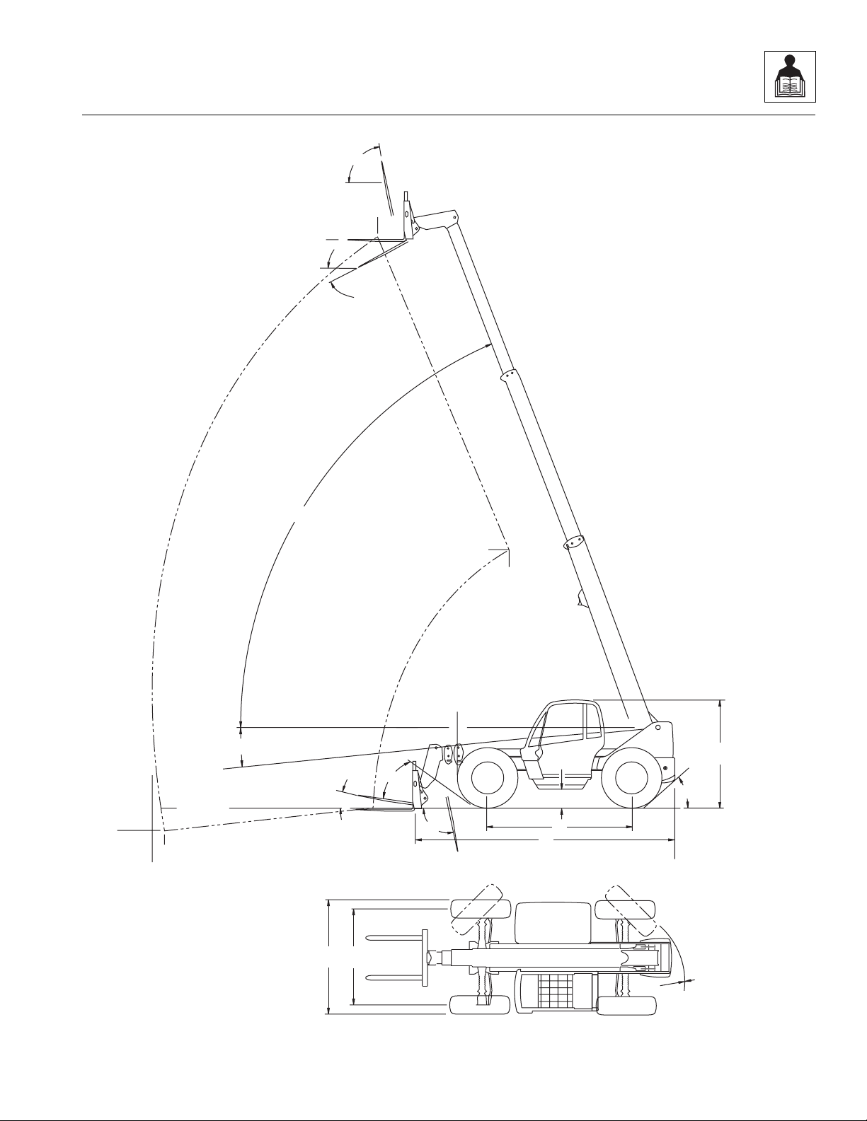
2.5 SPECIFICATIONS
2.5.1 Vehicle Dimensions
With 15.50-25 Radial Tires
Description Specifications
(A) Length (without Forks) 248" (6.299 mm)
(B) Width 101" (2.565 mm)
(C) Height (Boom Lowered) 93" (2.362 mm)
(D) Wheelbase 131" (3.327 mm)
(E) Tread Center 84" (2.134 mm)
(F) Ground Clearance
(at the bottom of the hydraulic reservoir drain plug)
(G) Turning Radius, Curb to Curb 32.5' (9,91 m)
(H) Turning Radius, Clearance 45.5' (13,9 m)
(I) Maximum Lift Height, Boom Extended 42' 4" (12,9 m)
(J) Maximum Lift Height, Boom Retracted 20' 3" (6,2 m)
(K) Maximum Below Grade Depth, Boom Extended 1' 8" (0,5 m)
(L) Maximum Reach, from Front of Front Tires 30' (9,1 m)
(M) Maximum Reach at Maximum Lift Angle, Boom Extended 6' 2" (1,9 m)
(N) Maximum Reach at Maximum Lift Angle, Boom Retracted -2' 8" (-0,8 m)
(O) Maximum Reach at Minimum Lift Angle, Boom Extended 29' (8,8 m)
(P) Maximum Boom Lift Angle 70.0°
(Q) Minimum Boom Lift Angle -2.9°
(R) Percentage of Slope of Approach >45°
(S) Percentage of Slope of Departure >45°
Fork Tilt Angle:
(T) At Maximum Boom Angle - UP 84.0°
15.1" (383 mm)
(U) At Maximum Boom Angle - DOWN -23.4°
(V) At Minimum Boom Angle - UP 12.2°
(W) At Minimum Boom Angle - DOWN -30.3°
Frame Sway Angle (Not Shown):
Right 10.0°
Left 10.0°
2.10
Model MMV Rev. 12/04
Page 27
General Information, Specifications and Maintenance
T
M
I
U
P
J
N
0.0
Q
V
R
F
K
W
D
A
C
S
O
L
Model MMV Rev. 12/04
EB
G & H
MM2230
2.11
Page 28
General Information, Specifications and Maintenance
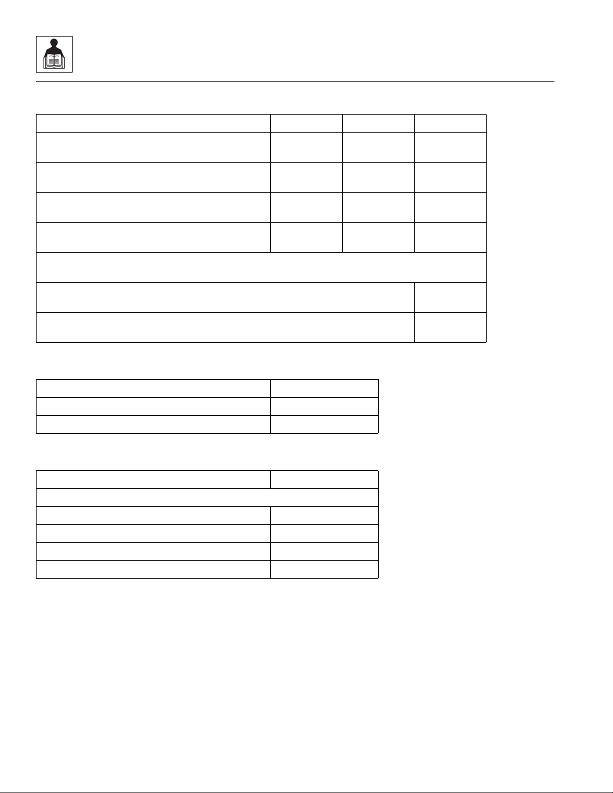
2.5.2 Vehicle Weights
Vehicle Configuration Front Axle Rear Axle Total
Without Carriage 9,250 lbs
(4.196 Kg)
With 11K Carriage 11,200 lbs
(5.080 Kg)
With 7K Carriage 12,900 lbs
(5.851 Kg)
With Both Carriages 14,800 lbs
(6.713 Kg)
Working Weight (Vehicle working weight is figured with one of the configurations listed above,
25%-full fuel tank, and radial tires [no hydrofill]):
Operating Load 7K Carriage 7,000 lbs
Operating Load 11K Carriage 11,000 lbs
17,650 lbs
(8.006 Kg)
16,900 lbs
(7.666 Kg)
16,400 lbs
(7.439 Kg)
15,700 lbs
(7.122 Kg)
26,900 lbs
(12.202 Kg)
28,100 lbs
(12.746 Kg)
29,300 lbs
(13.290 Kg)
30,500 lbs
(13.835 Kg)
(3.175 Kg)
(4.989 Kg)
2.5.3 Attachment Weights
Description Weight
7K Carriage 2,300 lb (1.043 kg)
11K Carriage 1,300 lb (590 kg)
2.5.4 Performance Specifications
Description Speed
Travel Speed (Radial Tires, No Load):
First Gear 3.5 mph (5,6 km/hr)
Second Gear 5.7 mph (9,2 km/hr)
Third Gear 13.5 mph (21,7 km/hr)
Fourth Gear 19.4 mph (31,2 km/hr)
2.12
Model MMV Rev. 12/04
Page 29

General Information, Specifications and Maintenance
2.5.5 Hydraulic Cylinder Performance Specifications
Note: Vehicle with no load, engine at full throttle, hydraulic oil warm (80° F [27° C] minimum), engine at operating
temperature
.
Function Approximate Times,
in Seconds
7K Carriage
Boom Extend 17.00 17.00
Boom Retract 23.60 23.60
Boom Lift Retracted 17.50 17.50
Boom Lower Retracted 19.80 19.80
Attachment Tilt - UP 7.60 7.60
Attachment Tilt - DOWN 7.30 7.30
Frame Sway Left to Right with Boom Down *12.00 to 15.50 *12.00 to 15.50
Frame Sway Left to Right with Boom Above 40°
and Emergency Brake Engaged
Frame Sway Right to Left with Boom Down *12.00 to 15.50 *12.00 to 15.50
Frame Sway Right to Left with Boom Above 40°
and Emergency Brake Engaged
Fork Side Shift
Left Cylinder, Right to Left 13.00 13.30
Left Cylinder, Left to Right 22.00 11.40
*17.50 to 33.40 *17.50 to 33.40
*21.50 to 43.00 *21.50 to 43.00
Approximate Times,
in Seconds
11K Carriage
Right Cylinder, Right to Left 13.00 13.30
Right Cylinder, Left to Right 22.00 11.40
* All times listed are approximate MAXIMUM times except where noted. Noted times are given
as a minimum to maximum range.
Model MMV Rev. 12/04
2.13
Page 30
General Information, Specifications and Maintenance
2.5.6 Electrical System
Description Specifications
Battery:
Type, Rating 12 VDC, Negative (-) Ground, Maintenance Free
Quantity 2
Reserve Capacity 1225 Cold Cranking amps @ 0° F (-18° C)
Group/Series HASP-FT
Alternator 24V/70 amps
Fuses - Standard Blade Style:
Switch Lamps, Service Brake, Hourmeter 2 amps
LMI System 3 amps
Fuel Shut-off Solenoid (FSOS), Transmission Gear,
5 amps
Transmission Direction, Steer Mode, Parking Brake
Joystick Logic Panel, Horn, Front Wiper/Washer, Top Wiper/
7.5 amps
Washer, Rear Wiper, Left Fork Shift, Right Fork Shift
Front Dash Display Panel, Ignition Pre-heat, Air Conditioner
15 amps
Condenser Fan Motor
Heater, Normal Lights, Blackout Lights 25 amps
Main, Power Window 30 amps
Fuses -
Battery Equalizer 125 amps
Circuit Breaker
Ignition Switch 12 volt/ 50 amp
Relays:
Neutral Engage Relay 12 volt
Work Light Power Relay 24 volt
High Beam Power Relay 24 volt
Brake Light Relay 12 volt
Light Power Relay 12 volt
Blackout Ignition Relay 12 volt
Normal Lights Ignition Relay 12 volt
Reverse Signal Relay 12 volt
Door Window Relay 12 volt
Closed Cab Accessory Power Relay 12 volt
Fuel Shut Off Solenoid Relay 12 volt
Air Conditioner Condenser Fan 12 volt
2.14
Model MMV Rev. 12/04
Page 31

General Information, Specifications and Maintenance
2.5.7 Engine Performance Specifications
Note: Engine manufacturer's maximum “high idle” setting is lockwired and sealed. DO NOT disturb this setting.
Description Specifications
Engine Make/Model Cummins Turbo/4BTA3.9
Displacement 239 in
Horsepower 116 HP @ 2500 rpm
Number of Cylinders 4
Engine High Idle with No Load 2750 ±100
Engine Low Idle 1050 ±50 rpm
Fuel Delivery Fuel Injection
Air Cleaner Dry Type, Replaceable Primary and
Peak Torque 407 lb/ft @ 1500 rpm
Average Fuel Consumption, Depending on Load/Duty 2.67 gal/hr (2,22 Imp gal/hr, or 10,1 l/hr)
3
(3.9 liters)
Safety Elements
Model MMV Rev. 12/04
2.15
Page 32

General Information, Specifications and Maintenance
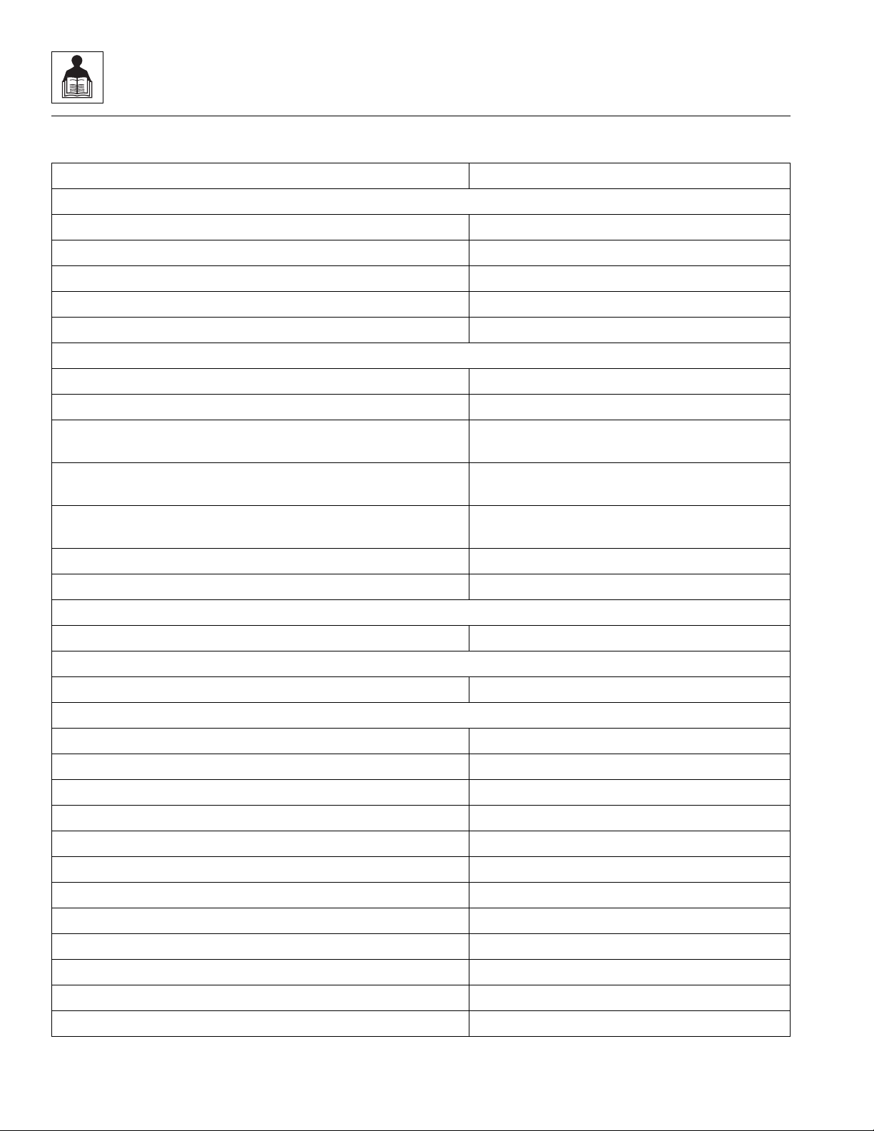
2.5.8 Fluid and Lubricant Capacities
Fluid & Lubricant Description Specifications
Engine Crankcase Oil:
Capacity with Filter Change 13.3 qt (12,6 liters)
Filter Capacity 1.3 qt (1,2 liters)
Oil Type
(Refer to
Fuel Tank:
Total Capacity 35.5 gal (134 liters)
Usable Capacity 33.5 gal (127 liters)
Type of Fuel Above 32° F (0° C) Standard No. 2 Diesel. (Refer to
Type of Fuel Below 32° F (0° C) 50/50 Mix of #1 and #2 Diesel Fuels. (Refer to
Alternate Fuel JP-5, JP-8 and Jet A-1
Cooling System:
Capacity w/o Heater
(including 1.5 qt [1,4 liters]
for overflow bottle)
Overflow Bottle Capacity 3.0 qt (2,8 liters)
Type of Fluid 50/50-mix of ethylene glycol and water. (Refer to
Transmission:
Capacity w/Filter Change 12 qt (11,4 liters)
Section 2.6.5, Engine
Above 23° F (-5° C) use SAE 15W40 Diesel Engine Oil.
.)
23° F (-5° C) to -25° F (-32° C) use 5W30
Below -25° F (-32° C) use 0W30
Oil Meeting MIL-PRF-2104G Specifications is Also acceptable
Section 2.6.5, Engine
Section 2.6.5, Engine
12.5 qt (11,8 liters)
.)
.)
Section 2.6.5, Engine
.)
Filter Capacity 1 qt (1 liter)
Typ e o f O i l
(Refer to
sion
Transfer Case:
Capacity 1.5 qt (1,4 liters)
Typ e o f O i l
(Refer to
Section 2.6.6, Transmis-
.)
Section 2.6.1, Axles (Differential Housings) and Transfer
Case
.)
Axle (Differential Housing):
Capacity 10.5 qt (10,0 liters)
Typ e o f O i l
(Refer to
Section 2.6.1, Axles (Differential Housings) and Transfer
Case
.)
2.16
Above 125° F (50° C) Use MIL-PRF-2104G Grade 15W40
14° F (-10° C) to 125° F (50° C) use MIL-PRF-2104G Grade 10W30 (Universal
Tractor Fluid)
Below 14° F (-10° C) use DEXRON lll (Automatic Transmission Fluid)
Above 100° F (38° C) use MIL-PRF-2104G Grade 15W40
Below 100° F (38° C) use MIL-PRF-2104G Grade 10W30 (Universal Tractor
Fluid)
Above 100° F (38° C) use MIL-PRF-2104G Grade 15W40
Below 100° F (38° C) use MIL-PRF-2104G Grade 10W30 (Universal Tractor
Fluid)
Model MMV Rev. 12/04
Page 33

General Information, Specifications and Maintenance
Fluid & Lubricant Description Specifications
Axle (Wheel Ends):
Capacity 1.3 qt (41.6 fl oz, or 1,2 liters)
Type of Oil
(Refer to
Section 2.6.1, Axles (Differential Housings) and Transfer
Case
.)
Hydraulic System:
System Capacity 41.3 gal (156 liters)
Reservoir Capacity 28.5 gal (108 liters)
Type of Oil
(Refer to
System
Section 2.6.4, Hydraulic
.)
Above 100° F (38° C) use MIL-PRF-2104G Grade 15W40
Below 100° F (38° C) use MIL-PRF-2104G Grade 10W30 (Universal Tractor
Fluid)
14° F (-10° C) & Above use MIL-PRF-2104G Grade 10 Hydraulic Oil
125° F (50° C) & Below use DEXRON lll (Automatic Transmission Fluid)
2.5.9 Hydraulic System
Description Specifications
Valve Relief Settings:
Main System Relief 3500 ±100 psi (241 ±6,9 bar)
Port Relief Boom - Hoist/Lower/Extend/Retract 3200 ±100 psi (220,6 ±6,9 bar)
Port Relief Fork Tilt (Both Sides) 3500 ±100 psi (241 ±6,9 bar)
Stabilizer Cylinder 75-150 psi (5,2-10,3 bar)
Power Steering Relief 2500 ±100 psi (172,3 ±7 bar)
Standby Pressure 200 ±50 psi (13,8 ±3,4 bar)
Pilot Pressure 550 ±100 psi (37,9 ±7 bar)
Parking Brake Relief 650 ±50 psi (44.8 ±3,4 bar)
Model MMV Rev. 12/04
2.17
Page 34

General Information, Specifications and Maintenance
2.5.10 Tires
Description Specifications
Tire Size 15.5R25, L-2, (2 Star Minimum) Radial
Wheel Lug Nut Torque 430-470 lb/ft (583-637 Nm)
Air Pressure 87 psi (600 kPa)
Tire Footprint Area (area is established under max. tip load):
Vehicle with 7K Carriage with No Load
(15.5R25, L-2, 2 Star tires at specified air pressure):
Vehicle with 7K Carriage with Rated Load
(15.5R25, L-2, 2 Star tires at specified air pressure):
Vehicle with 11K Carriage with No Load
(15.5R25, L-2, 2 Star tires at specified air pressure):
Vehicle with 11K Carriage with Rated Load
(15.5R25, L-2, 2 Star tires at specified air pressure):
Maximum Ground Pressure
(maximum ground pressure at tip =
(machine weight + load) / (2 x footprint area):
126 in
183 in
129 in
209 in
2
(810 cm2)
2
(1.180 cm2)
2
(835 cm2)
2
(1.350 cm2)
Vehicle with 7K Carriage with No Load
(15.5R25, L-2, 2 Star tires at specified air pressure):
Vehicle with 7K Carriage with Rated Load
(15.5R25, L-2, 2 Star tires at specified air pressure):
Vehicle with 11K Carriage with No Load
(15.5R25, L-2, 2 Star tires at specified air pressure):
Vehicle with 11K Carriage with Rated Load
(15.5R25, L-2, 2 Star tires at specified air pressure):
2.5.11 Miscellaneous Specifications
Description Specifications
Steering Wheel:
Maximum Number of Turns, Lock to Lock 4.25 turns
Minimum Number of Turns, Lock to Lock 3.75 turns
156 psi (1.070 kPa)
174 psi (1.200 kPa)
152 psi (1.050 kPa)
185 psi (1.275 kPa)
2.18
Model MMV Rev. 12/04
Page 35

2.5.12 Tamper Proofing
General Information, Specifications and Maintenance
A tamper-proof means is in place on the following
adjustable components prior to machine shipment. This
can either be tamper-proof paint, or a steel tamper-proof
cap. DO NOT attempt to defeat, by-pass or alter any
tamper-proof device.
• Main Valve Port Relief Valves [5]
• Fork Cylinder Counterbalance Valves [2]
• Secondary Function Manifold Valves [2]
• Unloader Valve [2]
• Main System Relief Valve [1]
2.5.13 Fork Ratings
All approved forks for this vehicle are marked with a
maximum load capacity rating. This rating (1) is stamped
on the right edge of the fork just below the fork pivot
shaft (2). The rating is listed in U.S. pounds and based
upon a 24" (610 mm) load center (3) (11K carriage) or
48" (1219 mm) load center (3) (7K carriage). This rating
specifies the maximum load capacity that the individual
fork can safely carry at the maximum specified load
center.
Since forks are always used in multiples, the total rating
of any combination of forks will be the sum of their rated
capacity. All forks should be used in matched pairs.
WARNING: DO NOT exceed the
total rated capacity of the specific pair of forks
being used. Forks can break causing loss of
load and possible death or serious personal
injury to the operator or personnel in the area.
If the total rated capacity of the forks exceeds
the capacity of the vehicle, the vehicle capacity
should not be exceeded.
The maximum load capacity for this vehicle is 7,000
pounds (3.175 Kg) for the 7K carriage or 11,000 pounds
(4.989 Kg) for the 11K carriage. The matched pair or set
of forks used on this vehicle should have total load
ratings which equal or exceed these weights. When the
load rating of the vehicle differs from the load capacity of
the forks, the lower value becomes the overall load
capacity.
Model MMV Rev. 12/04
3
1
2
OM0941
2.19
Page 36

General Information, Specifications and Maintenance
2.6 FLUIDS, LUBRICANTS AND
CAPACITIES
2.6.1 Axles (Differential Housings) and
Transfer Case
a. Axle and Transfer Case Lubricants
Recommended Oil/Temperature Range
MIL-PRF-2104G Grade 15W40
MIL-PRF-2104G Grade 10W30
(Universal Tractor Fluid*)
100° F (38° C)
*John Deere (JDM J20C Hy-Gard)
*Ford/New Holland ESN-M2C134-D (Hydraulic Oil 134)
*Massey Ferguson M-1141 (Permatran lll)
*Chevron 1000 THF
In general, use a oil that meets the following specifications:
Nominal viscosity at 104° F (40° C)....................... 55 cSt
Minimum viscosity at 212° F (100° C) .................. 9.1 cSt
Pour point (Maximum) .............................. -32° F (-36° C)
Flash point (Minimum) ............................ 392° F (200° C)
Minimum viscosity index ............................................ 135
b. Axle and Transfer Case Capacities
Axles (differential housings) .............. 10.5 qt (10,0 liters)
Transfer case......................................... 1.5 qt (1,4 liters)
OM1680
2.6.2 Wheel Ends
a. Wheel-End Lubricants
Recommended Oil/Temperature Range
MIL-PRF-2104G Grade 15W40
MIL-PRF-2104G Grade 10W30
(Universal Tractor Fluid*)
100° F (38° C)
*John Deere (JDM J20C Hy-Gard)
*Ford/New Holland ESN-M2C134-D (Hydraulic Oil 134)
*Massey Ferguson M-1141 (Permatran lll)
*Chevron 1000 THF
In general, use a oil that meets the following specifications:
Nominal viscosity at 104° F (40° C) ...................... 55 cSt
Minimum viscosity at 212° F (10° C) .................... 9.1 cSt
Pour point (Maximum).............................. -32° F (-36° C)
Flash point (Minimum).............................392° F (200° C)
Minimum viscosity index ............................................135
DO NOT add additional friction modifier to factory-filled
wheel ends. All wheel ends are factory-filled by the manufacturer with oil. If a wheel end is drained for service, it
should be refilled with the gear oils listed.
Note: DO NOT use synthetic oil without the express
written consent of the manufacturer.
b. Wheel-End Capacity
Wheel ends .......................1.3 qt (41.6 fl oz, or 1,2 liters)
OM1680
2.20
Model MMV Rev. 12/04
Page 37

General Information, Specifications and Maintenance
2.6.3 Lubrication Points (Grease Fittings)
Lubricants
When lubricating any component via the grease fittings,
use multi-purpose lithium-based grease with EP additives
that meets NLGI Grade 2 specifications. Products known
to meet these requirements include:
• AMOCO AMOLITH EP2
• ARCO LITHOLINE EP2
• BENZ MOLY-SERVICE EP2
• CHEVRON DUROLITH EP2
•CITGO H EP2
• GULF GULFCROWN EP2
• MOBILE MOBILUX EP2
• SHELL ALVANIA EP2
• SUN PRESTIGE 742EP
• TEXACO MULTIFAX EP2
Note: Refer to Section 2.13.1, Maintenance Schedule
and Checklist for lubrication intervals and grease fitting
locations.
2.6.4 Hydraulic System
a. Hydraulic Fluids
Recommended Oil/Temperature Range
MIL-PRF-2104G Grade 10
(Automatic Transmission Fluid)
DEXRON lll
14° F (-10° C)
125° F (50° C)
OM1700
2.6.5 Engine
a. Engine Fluids and Lubricants
1. Engine oil:
Recommended Oil/Temperature Range
MIL-PRF-2104G
Grade 15W40
(SAE 15W40)
MIL-PRF-2104G
Grade 5W30
(SAE 5W30)
MIL-PRF-2104G
Grade 0W30
(SAE 0W30)
-25° F (-32° C)
2. Cooling system (engine coolant):
In general, use a 50/50-mix of premium-quality ethylene
glycol (commonly referred to as “anti-freeze/anti-boil
over”) and water. Additives are not necessary.
3. Fuel:
In general, use No. 2 diesel fuel. From November 15 to
March 15 when operating in cooler climates where
ambient (outside air) temperatures are consistently at or
below 32° F (0° C), use a 50/50 mix of #1 and #2 diesel
fuels. Use good quality diesel fuel and change the fuel
filter regularly. Additives are not necessary.
The vehicle is also capable of operation on alternate
military fuels including JP-5, JP-8 and Jet A-1. However,
an up to 5% reduction in engine horsepower output can
be expected when using alternate military fuels due to the
lower BTU rating of these fuels.
23° F (-5° C)
OM1710
The hydraulic system is factory filled hydraulic oil that
meets the requirements of U.S. ordinance specification
MIL-PRF-2104G. When filling the hydraulic system, use
only an oil that meets these requirements or a grade10 oil
that meets the requirements of U.S. ordinance specification MIL-PRF-2104G.
b. Hydraulic System Capacity
System capacity ................................41.3 gal (156 liters)
Reservoir capacity.............................28.5 gal (108 liters)
Model MMV Rev. 12/04
2.21
Page 38

General Information, Specifications and Maintenance
b. Engine Capacities
1. Engine Oil Capacity
Capacity w/filter change .................... 13.3 qt (12,6 liters)
Filter....................................................... 1.3 qt (1,2 liters)
2. Cooling System Capacity
Capacity............................................. 12.5 qt (11,8 liters)
Overflow bottle capacity ........................ 3.0 qt (2,8 liters)
3. Fuel Tank Capacity
Total capacity ....................................35.5 gal (134 liters)
Usable capacity .................................33.5 gal (127 liters)
2.6.6 Transmission
a. Transmission Fluid
Recommended Oil/Temperature Range
MIL-PRF-2104G
Grade 15W40
MIL-PRF-2104G
Grade 10W30
(Universal Tractor Fluid*)
DEXRON lll
(Automatic
Transmission Fluid)
14° F (-10° C)
*John Deere (JDM J20C Hy-Gard)
*Ford/New Holland ESN-M2C134-D (Hydraulic Oil 134)
*Massey Ferguson M-1141 (Permatran lll)
*Chevron 1000 THF
In general, use a oil that meets the following specifications:
Nominal viscosity at 10° F (40° C)......................... 55 cSt
Minimum viscosity at 212° F (100° C) .................. 9.1 cSt
Pour point (Maximum) .............................. -32° F (-36° C)
Flash point (Minimum) ............................ 392° F (200° C)
Minimum viscosity index ............................................ 135
125° F (50° C)
OM1690
2.6.7 Air Conditioning
a. Air Conditioning Fluid
Type ...................................................................... R134a
b. Air Conditioning System Capacity
System Capacity ...................................... 3.0 lbs (1,4 kg)
2.6.8 Drive Shaft Splines
IMPORTANT: DO NOT disassemble any of the drive
shafts (refer to Section 6, Transfer Case and Drive
Shafts of this manual for information covering drive
shafts and U-joints). To help ensure optimum performance, the drive shaft assemblies are specially balanced as a unit at the factory. When servicing any flange
yoke, slip yoke or drive shaft tube, order a complete
assembly. Refer to the appropriate parts manual for
ordering information.
Respective of the above statement, should it become
necessary to coat the transmission input drive shaft
splines, use molybdenum disulfide grease. Molybdenum
disulfide grease specifically formulated for this purpose is
marketed by several manufacturers under various
names, including:
Aldrich Chemical Co., Inc.
Product name:
Catalog Number 23,484-2
Package Size: 5 g (0.175 oz)
100 g (3.5 oz)
500 g (17.5 oz)
Contact:
Aldrich Chemical Co., Inc.
P.O. Box 335
Milwaukee, WI 53201 USA
Phone: (414) 273-3850
DOW CORNING INC.
Product name:
Contact:
Dow Corning Corporate Center
P.O. Box 994
Midland, MI 48686-0994 USA
Phone: (517) 496-4400
Aldrich MOLYBDENUM (IV) SULFIDE
MOLYKOTE® 77 Paste
,
b. Transmission Capacity
Capacity w/filter change ................ 12 quarts (11,4 liters)
Filter............................................................... 1 qt (1 liter)
2.22
Model MMV Rev. 12/04
Page 39

General Information, Specifications and Maintenance
2.6.9 General Anti-Corrosion
a. Anti-Corrosion Compound
For general anti-corrosion protection, use a wax film
rust inhibitor that provides a protective film two tenthousandths of an inch (0.0002" or 0,00005 mm) thick.
One such rust inhibitor that is specifically formulated for
this purpose is
LPS 3
. It is marketed by:
LPS Laboratories, Inc.
4647 Hugh Howell Rd.
Tucker, GA 30085-5052 USA
Phone: 1-800-241-8334
Fax: (770) 493-9206
Note: Anti-corrosion protection is especially important in
frame and stabilizer cylinder pin support bores for protection from fretting corrosion wear.
b. Anti-Corrosion Need Areas
Coat all unplated pins and all bores for cylinder pins,
attachment pivot pins, chain sheave pins, the quick attach
lock pin, and all quick attach lock pin bores. On the boom,
coat the fork shaft and unpainted boom slide pathways.
2.6.10 Carriage Fork Shafts and Wear Pads
1
2
OM09402
2.6.11 Paint
Unless otherwise specified, paint components as indicated in the following sections.
a. Military Paint (CARC)
Durable, premium military paint is available in a production-sized one gallon (3,8 liters) container for extensive
repainting. Consult the appropriate parts manual for the
applicable part number and ordering information. Use
military paint on all vehicle components except as specified in paragraph
b. Black Paint
Durable, premium black paint is available in both a convenient 16-ounce (480 ml) spray can for touch-ups, and
in a production-sized one gallon (3,8 liters) container for
extensive repainting. Consult the appropriate parts manual
for the applicable part number and ordering information.
• Boom Angle Indicator Pointer
• Brake Pedal
•Radiator
• Seat Adapter Plate
• Radiator Shroud
• Transmission Oil Cooler
• Drive Shafts
• Transfer Case
•Forks
• Mirrors and Mirror Brackets
• Steering Column
• Wheels
• Air Conditioner Condenser
• Air Conditioner Condenser Guard
2.6.11, b
.
Use ONLY Teflon Lube to coat the entire fork shaft (1)
and the wear bar (2). DO NOT apply grease or any other
type of petroleum based lubricant to these areas. Grease
and petroleum based lubricants attract debris which will
prematurely wear the fork bushings and/or wear pads.
Apply Teflon Lube as needed to keep forks sliding
side-to-side smoothly, when putting vehicle into storage
or when Teflon Lube appears to be worn off or rust starts
to appear on the fork shaft or wear bar.
Model MMV Rev. 12/04
2.6.12 Thread Locking Compound
For general thread-locking purposes, Loctite® products,
manufactured by Loctite Corporation, are recommended.
Contact:
Loctite Corporation
1001 Trout Brook Crossing
Rocky Hill, CT 06067 USA
Phone: 1-800-LOCTITE (1-800-562-8483)
FAX: (860) 571-2460
Internet: http://www.loctite.com
®
Loctite
is a registered trademark of Loctite Corporation.
2.23
Page 40

General Information, Specifications and Maintenance
2.7 CLEANING
Dirt and abrasive dust reduce the efficient working life of
parts and systems, and lead to the costly replacement of
components. To help increase the service life of parts,
clean the exterior of all parts before beginning any repairs.
Use cleaning fluids and solvents suitable for cleaning
parts that do not create safety hazards. Certain types of
cleaning fluids can cause skin irritation and damage to
components (such as rubber, electrical parts, etc.).
Servicing the hydraulic system in particular requires
cleanliness.
Follow these precautions before attempting to service
any hydraulic component:
1. Flush hose and tube assemblies with a solvent
compatible with hose materials. Blow excess solvent
away with shop air.
2. Cap hydraulic fittings, hoses and tube assemblies,
and protect threads until time of installation. Clean
up any hydraulic fluid spillage immediately.
3. Flush hydraulic reservoir, fuel tank, and gear
housing with a suitable solvent to remove paint,
metal chips, etc.
4. Protect hydraulic system components from airborne
contaminants. Plug all cylinder, valve, reservoir, tank
and pump openings until time of installation.
5. Use clean, filtered oil when filling the system.
Maintain the hydraulic system at a minimum cleanliness
level of ISO code 18/15-particle ration count.
2.8 REPLACEMENT
ALWAYS use the correct tool when removing or replacing
any part or performing any service.
Some procedures may require the use of specialized
tools. If needed, many of these tools can be obtained
through Snap-on
Contact:
Snap-on Incorporated
P.O. Box 1410
Kenosha, WI 53141-1410 USA
Phone: 1-262-656-5200
Internet: http://www.snapon.com
Snap-on
ogies, Inc.
Replace o-rings, seals, and gaskets whenever they are
disturbed. NEVER mix new and old seals or o-rings,
regardless of apparent visual condition. ALWAYS lubricate new seals and o-rings with hydraulic oil before
installation.
®
is a registered trademark of Snap-on Technol-
®
tool distributors.
2.9 HOSES AND TUBES
2.9.1 Hose and Tube Inspection
1. Damaged, dented, crushed, or leaking hose and
tube fittings restrict oil flow and the operation of the
system being served. Fittings showing signs of
movement from their original position have failed and
must be replaced. ALWAYS replace the entire hose
or tube assembly if the fittings are damaged.
2. Hoses must remain in good condition. Obvious signs
of external hose wear or hydraulic fluid leaking or
weeping indicates the need to replace the hose
assembly. If in doubt, replace the hose.
3. Replace if any of the following conditions exist:
• Ballooning (replace hose immediately!)
• Kinking, crushing, stretching or deforming
• Concealed corrosion of wire reinforcement
• Chafed outer cover
2.9.2 Hose and Tube Installation
1. When installing a new hose, loosely connect each
end and verify that the hose takes up the designed
position before tightening the connection completely.
Tighten clamps sufficiently to hold the hose without
crushing it, and to prevent movement and chafing.
2. If a hose is replaced on a moving part, move the part
through its entire range of motion to verify that the
hose will not incur damage. Adjust as necessary.
3. When installing any hose, verify that it does not
become kinked or twisted.
4. NEVER allow freely moving or unsupported hoses to
contact each other or a related work surface. Such
contact causes chafing and reduces hose life.
2.24
Model MMV Rev. 12/04
Page 41

General Information, Specifications and Maintenance
2.10 BEARINGS
2.10.1 Bearing Removal
1. NEVER remove bearings unless absolutely
necessary! Always use the recommended puller to
reduce the risk of bearing or related component
damage.
2. When bearings or bushings are removed, verify that
the bearing or bushing is free from discoloration,
nicks, scuffing, and signs of overheating. If in doubt,
replace the bearing or bushing.
2.10.2 Bearing Cleaning
Wear safety glasses. Clean bearings acceptable for service in a suitable solvent. NEVER spin-dry a bearing with
compressed air; this can cause metal-to-metal contact
and bearing damage. Compressed air can also cause a
bearing to come apart. After cleaning a bearing, immerse
it in clean lubricating oil until needed.
2.10.3 Bearing Installation
1. Always install bearings carefully to help avoid
damaging their delicate surfaces.
2. Install bearings using one of the following methods:
• PRESS FIT for installation on rotating parts such
as shafts and gears;
• PUSH FIT into static locations such as reduction
gear housings.
3. Always install the bearing into the rotating part first
whenever possible.
4. Use a press or the proper installation tools when
installing a bearing or bushing.
5. In the absence of a press or proper installation tools,
carefully heat the casing and/or bearing in hot oil to
assist in the installation.
2.11 PRESSURE TESTING AND
ADJUSTMENT
Prior to pressure testing or adjustment, verify that all hoses and tubes are in good condition and that all fittings are
tight.
Use pressure gauges with the proper ranges and ratings
to measure the specified pressures.
Use correct test procedures to help prevent personal injury, damage to the system or test equipment.
Verify that the hydraulic oil is at proper operating temperature, 80-120° F (27-49° C), before adjusting the pressure reducing valve, or relief valves. If necessary,
operate the vehicle to raise the oil temperature. In the absence of a temperature gauge, the oil temperature can be
checked by placing a hand against the side or the bottom
of the reservoir; if the tank is too hot to keep the hand in
contact with it, the oil temperature should be within the
proper range.
2.12 AFTER SERVICE STARTUP AND
CHECKS
2.12.1 After Service Startup
Note: Refer to the Owners/Operators Manual for engine
cold-start procedures.
1. Check fluid levels.
2. Connect the negative (-) battery cable to the battery
(if it is disconnected).
3. Start and idle engine. Check for leaks from hydraulic
components, engine, axles, transmission, brakes
and reservoirs or tanks. Check the levels of all fluids
and lubricants.
4. Purge the hydraulic system of air by operating all
vehicle functions through their entire range of motion
several times.
5. Check for proper operation of all components.
6. Retract all cylinders fully. Turn the engine OFF and
check the hydraulic reservoir level. Recheck the level
when the hydraulic oil is cold.
7. Replace the hydraulic filter if required.
Model MMV Rev. 12/04
2.25
Page 42

General Information, Specifications and Maintenance
2.12.2 After Electrical/Electronic Component
Service
1. Check the torque of all fasteners securing replaced
electrical/electronic components.
2. Check wiring connections to components.
3. Verify that wiring components are dry and free of
moisture.
4. Check connectors for broken, frayed, or loose wires.
5. Check for brittle or frayed wire shielding.
6. Connect the negative (-) battery cable terminal to the
battery (if it is disconnected).
7. Check the operation of the replaced component(s).
2.12.3 After Hydraulic Component Service
1. Check torque of fasteners on replaced components.
2. Check that hoses and tubes are properly attached,
positioned, and tightly connected.
3. If a hydraulic component failed and contaminated
the system, flush the system, clean the hydraulic oil
reservoir (tank), and replace the hydraulic oil filter.
4. After normal hydraulic component maintenance,
check the hydraulic fluid level and add fluid as
required.
5. Start engine and bleed hydraulic system of air.
Operate all boom functions through their full range of
motion several times. Cycle the hoist and extend
cylinders to bleed air from the system. Visually
check for leaks.
6. Check operation of all systems in the hydraulic
circuit by operating the controls through all functions
several times.
2.12.4 After Brake System Service
1. Check the oil level in the axle and replenish with oil
as required.
2. Bleed the brakes.
3. Check brake pressure.
4. Check brake operation.
2.12.6 After Transmission Service or
Replacement
1. Check transmission oil level and fill to level with oil
as required. (Refer to
information on transmission lubricants.)
2. Replace transmission filter.
3. Check torque on drive shaft yoke retaining bolts.
Tighten these M12 bolts to 156 lb/ft (212 Nm).
4. Refer to the ZF 4 WG-98 TS Transmission Repair
Manual (ZF part number 5871 139 002, JLG part
number 8990418) for servicing the transmission
after overhaul or repair.
5. Wear suitable eye protection. When an overhauled
or repaired transmission is installed, thoroughly
clean the oil cooler lines to and from the
transmission.
6. Drain and flush the entire system.
7. Disconnect and clean all transmission lines. When
possible, remove transmissions lines from the
vehicle for cleaning.
8. Thoroughly clean transmission filter screens and
cases, and replace transmission filter elements.
Section 2.6.6, Transmission
for
CAUTION: DO NOT exceed 165 psi
(11,4 bar) when back flushing the oil cooler.
Applying too much pressure may damage the
oil cooler/radiator.
9. “Back flush” the transmission oil cooler with oil and
compressed air until all foreign material is removed.
Flushing in direction of normal oil flow does not
adequately clean the cooler. If needed, remove the
transmission oil cooler assembly from the vehicle.
DO NOT use flushing compounds for cleaning
purposes.
10. Reassemble all components and fill the transmission
with clean, fresh oil through the dipstick tube
opening until oil comes up to the FULL mark on the
transmission dipstick.
11. Run engine for two minutes at idle to help prime the
torque converter and transmission lines.
2.12.5 After Fuel System Service
1. Drain and flush fuel tank; if it was contaminated.
2. Bleed fuel system.
3. Fill fuel tank with fresh, clean fuel, as required.
2.26
Model MMV Rev. 12/04
Page 43

General Information, Specifications and Maintenance
12. Recheck the level of fluid in the transmission with the
engine running at idle.
13. Add oil as necessary to bring the fluid level up to the
FULL mark on the transmission dipstick. Install the
oil dipstick. Recheck the oil level when it reaches
operating temperature (180-200° F or 83-94° C).
14. Recheck all drain plugs, lines, connections, etc., for
leaks and tighten where necessary.
2.12.7 After Tire and Wheel Service
1. Check air pressure.
2. Be sure the lockwashers are properly positioned
under each wheel nut.
3. Check wheel nut torque. Tighten to 430-470 lb/ft
(583-637 Nm).
2.12.8 After Engine Service
Consult the qualified service agent (manufacturer’s representative and/or service manual) for proper procedures
before engine startup.
2.12.9 After Boom Service
1. Check wear pads.
2. Check chain tension adjustment.
3. Apply grease at all lubrication points (grease fittings).
4. Check for proper operation by operating all boom
functions through their full range of motion several
times.
2.12.10 After Axle Service
1. Check fluid levels.
2. Check torque on drive shaft flange yoke retaining
bolts. Tighten these M12 bolts to 156 lb/ft (212 Nm).
3. Be sure the lockwashers are properly positioned
under each wheel nut.
4. Check wheel nut torque. Tighten to 430-470 lb/ft
(583-637 Nm).
5. Check toe-in if required.
6. Apply grease at all lubrication points (grease fittings).
7. Refer to the axle manufacturer’s maintenance
manual for further information.
Model MMV Rev. 12/04
2.27
Page 44

General Information, Specifications and Maintenance
2.13 MAINTENANCE INSTRUCTIONS
WARNING: DO NOT service the
vehicle without following all safety precautions
as outlined in the “Safety Practices” section of
this manual. Failure to follow the safety practices may result in death or serious injury.
WARNING: DO NOT perform ser-
vice or maintenance on the vehicle with the
engine running. Contact with moving parts can
cause death or serious injury.
IMPORTANT: JLG recommends the use of environmentally sound waste storage and disposal practices.
NEVER drain fluids on the ground or into a sewer or
catch basin. Use suitable collection containers, then
store and/or dispose of waste products in an approved
and safe manner. Check and obey all Federal, State and/
or Local regulations regarding waste storage, disposal
and recycling.
This section contains a routine equipment checklist and a
maintenance schedule and checklist with references to
pertinent procedures and instructions. To help prevent
problems before they occur, follow the maintenance
schedule.
3
1
2
2.13.1 Maintenance Schedule and Checklist
a. 10 Hour Intervals
10
At ten-hour intervals, perform the following:
2
0
H
Drain
Fuel/Water
Separator
• Drain the fuel/water separator (refer to
2.13.7, Engine Fuel System
• Check the engine coolant level (refer to
2.13.4, Engine Cooling System
• Check the engine oil level (refer to
2.13.5, Engine Oil and Filter
Inspect
Wear Pads
Check
Engine
Coolant Level
Emergency Tire Inflation Tank
Check
Engine
Oil Level
Drain Water From
Check
Hydraulic
Oil Level
Check
Transmission
Oil Level
Inspect and/or Clean Air
Compressor Intake Filter
).
).
).
Check
Tire
Pressure
Section
Section
Section
MM3211
• Check the hydraulic reservoir oil level (refer to
Section 2.13.9, Hydraulic System Oil and Filter
• Check the transmission oil level (refer to
2.13.10, Transmission Oil and Filter
• Check the air pressure in the tires (refer to
tion 2.13.15, Wheels and Tires
).
• Check boom wear pad thickness (refer to
2.13.19, Boom Wear Pad Maintenance
Section
).
Sec-
Section
).
• Drain water from emergency tire inflation tank
(refer to
tion System
Section 2.13.16, Emergency Tire Infla-
).
• Inspect and/or clean air compressor intake filter
(refer to
tion System
Section 2.13.16, Emergency Tire Infla-
).
).
OS1171
Note: Lubrication (1) and maintenance (2) chart decals
are located inside the engine compartment cover (3).
These decals contain a general maintenance schedule
that should be followed to maintain the vehicle in good
operating condition. The same schedule information is
presented in this manual, except that it contains a more
detailed account of how to perform these specific maintenance operations.
2.28
Model MMV Rev. 12/04
Page 45

General Information, Specifications and Maintenance
b. At First 50 Hours of Use
50
Change Engine
Oil and Filter
Change
Axle Oil
Change
Transmission
Filter
Wheel End Oil
Change
Change
Hydraulic
Filter
Change
Transfer
Case Oil
430-470 (583-637)
L
B
/
F
T
(
N
m
)
Check
Wheel Lug Nut Torque
MM3200
When the vehicle completes its first 50 hours of use, perform the following:
• Change the engine oil and filter (refer to
2.13.5, Engine Oil and Filter
).
• Change the transmission filter (refer to
2.13.10, Transmission Oil and Filter
• Change the hydraulic filter (refer to
2.13.9, Hydraulic System Oil and Filter
• Change the transfer case oil (refer to
2.13.14, Transfer Case Oil
• Change the axle oil (refer to
Axle Oil
).
).
Section 2.13.11,
• Change the wheel end oil (refer to
2.13.13, Wheel End Oil
).
• Check the wheel lug nut torque (refer to
2.13.15, Wheels and Tires
).
Section
Section
).
Section
).
Section
Section
Section
• Check the wheel end oil level (refer to
2.13.13, Wheel End Oil
• Inspect Extend Chains (refer to
Boom Chain Tension & Adjustment
).
Section 2.13.21,
).
• Apply multi-purpose grease at all lubrication
points. Lubricate the following components via
the grease fittings with good grade of a multipurpose, lithium-based grease every 250 hours
(remove all excess grease):
C
A
B
2/ 2/
A
B
F
D
C
A
D
A
A
E
B
A
E
A
F
Section
A
c. 250 Hour Intervals
250
250
Change
Change
Engine Oil & Filter
Engine Oil & Filter
Check
Check
Wheel EndOil Level
Wheel EndOil Level
Check
Check
Transfer Case Oil Level
Transfer Case Oil Level
Lubricate
Lubricate
Fittings
Fittings
Check
Check
Axle Oil Level
Axle Oil Level
Extend Chains
Extend Chains
At 250 hour intervals, perform the following:
• Change the engine oil and filter (refer to
2.13.5, Engine Oil and Filter
).
• Check the transfer case oil level (refer to
2.13.14, Transfer Case Oil
• Check the axle oil level (refer to
Axle Oil
Model MMV Rev. 12/04
).
).
Section 2.13.11,
Inspect
Inspect
MM3220
Section
Section
B B
MM4150
A. Hydraulic cylinder pins ............................ 14 points
B. Powertrain slip joints & axle U-joints....... 11 points
C. Boom pivot pin .......................................... 4 points
D. Quick attach pivot pin................................ 2 points
E. Axle pivot pins........................................... 4 points
F. Chain sheave............................................. 2 points
Note: Shorten the lubrication interval on all lubrication
points when operating under severe conditions.
2.29
Page 46

General Information, Specifications and Maintenance
d. 500 Hour Intervals
500
).
Change
Change
Fuel
Filter
Section 2.13.2, Air
Section 2.13.7,
Change
Axle Oil
Check
Check
Air Intake
Fan
System
Belt
Section 2.13.11,
Section
).
).
Section 2.13.12,
).
Section 2.13.8,
Section 2.13.2,
Section 2.13.22,
Section
Change
Air
Filter
At 500 hour intervals, perform the following:
• Change the air filter (refer to
Cleaner
).
• Change the fuel filter (refer to
Engine Fuel System
e. 1,000 Hour Intervals
0001
Check
Boom Chain
Tension
Change
Transfer Case Oil
Change
Transmission
Oil and Filter
P
Check Brake
Disk Wear
Hydraulic
Oil and Filter
At 1,000 hour intervals, perform the following:
• Check boom chain tension (refer to
2.13.21, Boom Chain Tension & Adjustment
• Change the transmission oil and filter (refer to
Section 2.13.10, Transmission Oil and Filter
• Change the hydraulic oil and filter (refer to
2.13.9, Hydraulic System Oil and Filter
• Change the axle oil (refer to
Axle Oil
).
• Change the wheel end oil (refer to
2.13.13, Wheel End Oil
• Change the transfer case oil (refer to
2.13.14, Transfer Case Oil
• Check brake disc wear (refer to
Brake Disc Wear Check
• Check the fan belt (refer to
Engine Fan Belt & Air Conditioner Compressor
Belt
).
• Check air intake system (refer to
Air Cleaner
).
• Lubricate Boom Chains (refer to
Chain Lubrication
).
MT00701
Change
Wheel End Oil
Lubricate
Boom Chain
MM4160
).
).
Section
).
Section
f. 2,000 Hour Intervals
0002
Change
Engine
Coolant
MS1380
At 2,000 hour intervals, perform the following:
• Change the engine coolant (refer to
2.13.4, Engine Cooling System
Section
).
2.13.2 Air Cleaner
a. Engine Air Restriction Warning Indicator
1
The operator’s display panel includes an indicator light
(1) that illuminates to alert the operator when restricted
air flow to the engine is sensed. This indicates that the air
filter needs servicing. NEVER operate the vehicle without
the air cleaner assembly and both filters in place.
b. Air Cleaner Element: Change
OM07312
500
MS21802 OS0790
As indicated by the air cleaner restriction indicator, and/or
every 500 hours, change the air filter element.
2.30
Model MMV Rev. 12/04
Page 47

General Information, Specifications and Maintenance
Outer Primary Element
All air cleaner manufacturers agree that attempting to
clean or wash an element increases the chance for element damage. It is highly recommended that you consider the value of cleaning an element against the risks that
could lead to engine damage. Adopt the policy that all elements should be replaced with new
and not cleaned.
Inner Safety Element
An inner safety element should NEVER be washed or reused. ALWAYS
Replace safety elements after every third primary element change. DO NOT remove a safety element until the
inside of the air cleaner canister is thoroughly cleaned.
This will help prevent dirt that could damage the engine
from entering the induction manifold.
install a new element.
CAUTION: NEVER run the engine
with only the safety element installed. Severe
engine damage will result from dust entering
the engine.
4. If replacing the inner element (8) at this time,
carefully slide the element out. Always discard this
element and replace with a new element.
5. Slide the new primary element over the inner
element making sure the sealing edge is flush with
the base of the air cleaner.
IMPORTANT: DO NOT apply any type of petroleum
product to the sealing surface of the filter in an attempt to
get a more positive seal. This will cause sealing surface
damage and allow dirt to by-pass the filter. Use liquid
dishwashing soap (Ivory, Dawn, etc.) on the seal of the
filter only.
6. Position the canister cover (3) in place, turn
clockwise to lock into position and secure in place by
pushing the air cleaner cover lock (2) all the way in.
8
5
2
4
3
OM0980
To change elements:
1. Pull the air cleaner cover lock (2) out, turn the air
cleaner cover (3) counter-clockwise and remove the
cover from the air cleaner canister (4).
2. Remove the primary element (5). Inspect the
element for damage. Damaged elements should
never be reused.
3. Thoroughly clean the interior of the air filter canister
(6) and vacuator valve (7).
3
2
6
7
c. Air Intake System-Inspection
OM0990
0001
MS21902
Inspect the intake piping for cracked hoses, loose
clamps, or punctures that can allow dirt or debris to enter
the combustion chamber. If dirt or debris is allowed to enter the combustion chamber, it can severely damage the
engine. If necessary, tighten or replace parts to help prevent air intake system leakage.
OT0880
Model MMV Rev. 12/04
2.31
Page 48

General Information, Specifications and Maintenance
2.13.3 Closed Cab Air Filters
The closed cab has two air filters, the recirculation air filter and the fresh air intake filter. Both of these filters require periodic inspection and maintenance.
Recirculation Air Filter
Periodically remove two truss-head bolts (1), vent
cover (2) the recirculation air filter (3) located directly below the seat. Inspect the filter. Gently hand wash with water, a mild detergent may also be used if the filter is
saturated with dirt.
3
2
Fresh Air Intake Filter
Periodically remove the cab rear panel and inspect the
fresh air intake filter (7). The filter must be cleaned
sometimes as often as twice a day, depending on the
operating environment. This is done by removing the filter
and shaking it. The filter can be gently hand washed with
water. A mild detergent may also be used if the filter is
saturated with dirt. When re-installing the filter make sure
the filter is held in place with both filter latches (4 and 6).
The filter will clean outside air when pressurizing the cab.
The filter should be replaced at 250 hour intervals under
normal operating conditions and at 50 hour intervals
under extreme operating conditions.
Note: Correctly position the filter so the air flow (5) is
directed into the cab.
5
4
6
7
1
OS1791
OS1810
4. Filter latch
5. Direction of air flow
6. Filter latch
7. Fresh air intake filter
2.32
Model MMV Rev. 12/04
Page 49

General Information, Specifications and Maintenance
2.13.4 Engine Cooling System
a. Engine Coolant Level Check (10 Hour Intervals)
10
MS21402
1. Level the vehicle, ground the attachment, place the
travel select lever in the [N] NEUTRAL position, place
the neutral lock lever in the [N] NEUTRAL LOCK
position, engage the parking brake switch and shut
the engine OFF.
2. Unlatch and open the engine cover.
3. Check the coolant level in the overflow bottle (8).
When the coolant is hot, the bottle should be half to
three-quarters full. When the coolant is cool, the
bottle should be one-quarter to half full. Add coolant
(use a 50/50 mixture of ethylene glycol and water) as
required through the overflow bottle.
OS0800
b. Drain and Flush the Radiator
2000
MS3000
1. Level the vehicle, ground the attachment, place the
travel select lever in the [N] NEUTRAL position, place
the neutral lock lever in the [N] NEUTRAL LOCK
position, engage the parking brake switch and shut
the engine OFF.
2. Place an Accident Prevention Tag on both the
ignition switch and steering wheel, stating that the
vehicle should not be operated. (Refer to
1.5, Accident Prevention Tag Usage
WARNING: DO NOT attempt this
procedure when the engine is hot. Wait for the
engine, muffler, and tailpipes to cool down
before proceeding. Failure to do so could result
in severe burns.
OS0810
Section
.)
3. Unlatch and open the engine cover. Allow the engine
to cool before proceeding. Draining and flushing the
8
cooling system while the engine is hot can cause
cracks in the engine block.
WARNING: NEVER remove the
radiator cap while the engine is hot. The cooling
system is under pressure. Hot coolant can
cause severe burns or eye injury. Wear protective clothing and safety glasses.
OM1630
Model MMV Rev. 12/04
2.33
Page 50

General Information, Specifications and Maintenance
4. Slowly turn the radiator cap (1), located in the upper
radiator hose, to the first stop and allow any
pressure to escape. Remove the radiator cap.
5. Place a funnel (2) at the base of the radiator to
channel the drained coolant into a container.
Unscrew the radiator drain plug (3) and allow the
coolant to drain into the funnel.
6. Detach the hose (4) from the fitting (5) on the neck of
the radiator fill tube and drain any coolant from the
overflow bottle into the funnel.
7. Flush the radiator with clean water, and flush drain
again.
5
1
4
3
2
OM1640
8. Remove the engine block drain plug (6) and drain
any coolant from the engine block. Replace the
engine block plug.
9. Transfer the coolant to a container with a cover and
label the container “Used Anti-freeze.” Dispose of the
used coolant at an approved recycling facility.
10. Reconnect the hose (4) to the fitting on (5) the neck
of the radiator fill tube. Close the radiator drain plug
or petcock.
7
OM1300
11. Open the petcock (7) on the turbo aftercooler.
12. Fill the radiator completely with a 50/50 mixture of
ethylene glycol and water. Replace the radiator cap.
Add coolant to the overflow bottle until the bottle is
half to three-quarters full. This “overfilling” will
compensate for any air in the cooling system.
13. Close the petcock (7) on the turbo aftercooler.
14. Clean dirt and debris from the radiator core.
15. Start and run the engine until normal engine operating
temperature is reached, then turn the engine OFF.
Check for leaks while the engine is cooling.
16. After engine has cooled for several minutes, open
the petcock (7) on the turbo aftercooler. Allow air in
the system to escape. Close the petcock when
coolant starts flowing from the petcock. All air is now
purged from the aftercooler.
17. Allow the engine to cool. Check the radiator coolant
level again and top off as needed with a 50/50
mixture of ethylene glycol and water. Replace the
radiator cap.
18. The overflow bottle should be one-quarter to
one-half full. If not, fill as necessary with a 50/50
mixture of ethylene glycol and water.
2.34
6
OT0260
Model MMV Rev. 12/04
Page 51

General Information, Specifications and Maintenance
2.13.5 Engine Oil and Filter
a. Engine Oil Recommendations
The use of quality engine oil combined with the appropriate oil and filter change intervals are critical factors in
maintaining engine performance and durability. (Refer to
the chart below for recommended oil types for various operating conditions).
Recommended Engine Oil/Temperature Range
MIL-PRF-2104G
Grade 15W40
(SAE 15W40)
MIL-PRF-2104G
Grade 5W30
(SAE 5W30)
MIL-PRF-2104G
Grade 0W30
(SAE 0W30)
-25° F (-32° C)
Engine oil capacity, with filter change, is 13.3 quarts
(12,6 liters).
23° F (-5° C)
OM1710
b. Oil Level Check
10
MS21402 OS0820
1. Level the vehicle, ground the attachment, place the
travel select lever in the [N] NEUTRAL position, place
the neutral lock lever in the [N] NEUTRAL LOCK
position, engage the parking brake switch and shut
the engine OFF.
2. Open the engine cover.
3. Remove the engine dipstick (8). Check the oil mark
on the dipstick. The oil should be within the
crosshatched area of the dipstick.
4. Add oil as required. Replace the dipstick.
Full
Add
8
Model MMV Rev. 12/04
OT0060
2.35
Page 52

General Information, Specifications and Maintenance
c. Oil and Filter Change
50
OH26701 MS21702 OS0830
Change the oil and filter after the first 50 hours of vehicle
operation, at 250-hour intervals. To change the oil and
filter:
1. Operate the engine until it reaches operating
temperature (approximately five minutes).
2. Level the vehicle, ground the attachment, place the
travel select lever in the [N] NEUTRAL position, place
the neutral lock lever in the [N] NEUTRAL LOCK
position, engage the parking brake switch and shut
the engine OFF.
3. Place an Accident Prevention Tag on both the ignition
switch and steering wheel, stating that the vehicle
should not be operated. (Refer to
Accident Prevention Tag Usage
4. Open the engine cover.
250
Section 1.5,
.)
7. Allow the oil to drain completely into the receptacle.
Transfer the oil to a container with a cover and label
the container as used motor oil. Dispose of used oil
at an approved recycling facility.
8. Remove the oil filter (3) and clean the filter-sealing
surface. The oil filter is remotely mounted on a
bracket under the frame, in front of the transfer box.
Access the filter from under the vehicle.
9. Apply a thin coat of clean engine oil to the new filter
mating surface.
10. Install the new oil filter and hand tighten. Use an oil
filter wrench or strap to tighten the filter down an
additional one-quarter to half turn. DO NOT
overtighten.
11. Turn the oil drain petcock lever (2) clockwise and
lock into the CLOSED position. The petcock lever is
spring loaded and will lock in the CLOSED position.
12. Remove the engine oil fill cap (5) and add oil (refer to
the recommended engine oil/temperature range
chart on page 2.35 for recommended oil types for
various operating conditions). Engine oil capacity
with filter change is 13.3 qt (12,6 liters).
13. Reinstall the oil fill cap. Start the engine and allow it
to run for several minutes.
14. Shut off the engine. Wait several minutes, and then
check the oil level again on the dipstick (4). Add oil as
required. DO NOT overfill.
15. Look for oil leaks at the filter and drain plug. Tighten
as required.
2
5. Place an oil drain pan under the engine oil pan drain
hose (1). The hose is located under the engine up
behind the hydraulic oil reservoir.
6. Lift the petcock lever (2) up and turn
counterclockwise to OPEN and drain the oil from the
engine oil pan.
2.36
1
OM1310
4
3
OM1740
Model MMV Rev. 12/04
Page 53

General Information, Specifications and Maintenance
2.13.7 Engine Fuel System
a. Drain Water from Fuel-Water Separator/Filter
5
2.13.6 Engine Oil Sample Point
1. Open the engine cover.
2. Locate the oil sample valve (6) on the side of the
engine.
3. After oil sample has been taken, close the engine
cover.
MM4570
10
MS21402 OS0851
0
H
2
1. Level the vehicle, ground the attachment, place the
travel select lever in the [N] NEUTRAL position, place
the neutral lock lever in the [N] NEUTRAL LOCK
position, engage the parking brake switch and shut
the engine OFF. Allow the engine to cool.
2. Place an Accident Prevention Tag on both the
ignition switch and steering wheel, stating that the
vehicle should not be operated. (Refer to
1.5, Accident Prevention Tag Usage
Section
.)
3. Open the engine compartment cover.
4. Position a suitable glass container beneath the fuel
filter drain cock (7), located on the underside of the
fuel filter (8).
5. Loosen the fuel filter drain cock. Allow the water to
drain into the glass container until clear fuel is
visible. After draining is complete, tighten the drain
cock. Dispose of drainage properly.
6. Close the engine compartment cover.
6
Model MMV Rev. 12/04
OM1321
8
7
MM3240
2.37
Page 54

General Information, Specifications and Maintenance
b. Change Fuel Filter
500
MS21802 OS0870
Change the fuel filter every 500 hours of engine operation, or at shorter intervals with water evidence of contaminated fuel.
1. Level the vehicle, ground the attachment, place the
travel select lever in the [N] NEUTRAL position, place
the neutral lock lever in the [N] NEUTRAL LOCK
position, engage the parking brake switch and shut
the engine OFF. Allow engine to cool.
2. Place an Accident Prevention Tag on both the
ignition switch and steering wheel, stating that the
vehicle should not be operated. (Refer to
1.5, Accident Prevention Tag Usage
3. Open the engine cover. Clean around the fuel-filter
head (1).
4. Unscrew the fuel filter and dispose of properly.
5. Clean the filter head gasket surface and replace the
o-ring.
6. Fill the new fuel filter (2) with clean No. 2 diesel fuel.
Alternate fuels can also be used. They are: JP-5,
JP-8 or Jet A-1.
7. Lubricate the o-ring seal (3) with clean No. 2 diesel
fuel. Alternate fuels can also be used. They are:
JP-5, JP-8 or Jet A-1.
8. Install the fuel-filled filter and tighten by hand. DO
NOT over-tighten.
Section
.)
c. In-line Fuel Strainer
500
MS21802 OS0870
1. Level the vehicle, ground the attachment, place the
travel select lever in the NEUTRAL [N] position, place
the neutral lock lever in the [N] NEUTRAL LOCK
position, engage the parking brake switch and shut
the engine OFF. Allow engine to cool.
2. Place an Accident Prevention Tag on both the
ignition switch and steering wheel, stating that the
vehicle should not be operated. (Refer to
1.5, Accident Prevention Tag Usage
Section
.)
1
7
3
2
4
Note: DO NOT over-tighten. DO NOT tighten with
mechanical means (tools, etc.). Mechanical over-tightening may distort the threads or damage the o-ring seal.
9. Close the engine cover.
Controlled venting is provided at the injection pump
through the fuel drain manifold. Small amounts of air introduced by changing the fuel filter element will be vented
automatically as long as the element was filled with fuel
prior to installation.
2.38
5
3. Open the engine cover.
4. The in-line fuel strainer (4) is located down line from
the engine lift pump (5). Loosen the two hose
clamps (6) securing the strainer in place.
8
6
Model MMV Rev. 12/04
MM3240
Page 55

General Information, Specifications and Maintenance
5. Remove and properly dispose of the old strainer.
6. Install the new strainer with the arrow pointing
toward the lift pump.
7. Assemble the hoses to the strainer and tighten the
hose clamps.
8. Remove air from the fuel system. (Refer to
2.13.7, d. Venting Air from the Fuel System
9. Close the engine cover.
d. Venting Air from the Fuel System
Section
.)
WARNING: DO NOT vent air from
the fuel system of a hot engine. Allow the
engine to cool before attempting to purge air
from the fuel system. Failure to do so could
create a fire hazard.
Air must be vented from the fuel system whenever any
component between the fuel tank and the injection pump
has been disconnected, or when the system has been
emptied, or has run out of fuel.
IMPORTANT: DO NOT attempt to start the engine until
the injection pump has been filled and primed with fuel.
Serious damage to the lift pump will result due to lack of
proper lubrication.
1. To vent the low pressure lines and fuel filter, open
the vent screw (7), located on the filter head.
2. Operate the hand plunger (8) on the lift pump (5)
until fuel flowing from the fitting is free of air.
3. Tighten the vent screw and torque to 7 lb/ft (9 Nm).
The process of venting the high-pressure fuel lines (9)
involves energizing the starter motor, which rotates the
crankshaft, which, in turn, operates the fuel pump to
purge air from the high-pressure fuel lines.
WARNING: Diesel fuel under pres-
sure can penetrate the skin and cause serious
personal injury. Slowly loosen fittings and allow
release of residual pressure before removing
any fuel line.
4. Loosen one high-pressure line fitting (10) at the
injector (11). Operate the starter motor for 15
seconds. Wait two minutes. Operate the starter
motor again for 15 seconds. Repeat this process
until fuel, free of air, comes out of the injector fitting.
10
9
11
OS0990
5. Tighten the fitting to 22 lb/ft (30 Nm). Repeat this
procedure for each fitting until the engine runs
smoothly. With the engine running, visually check for
leaks. Turn the ignition switch OFF.
CAUTION: When cranking the
engine with the starter motor to vent air from
the fuel system, DO NOT energize the starter
solenoid or crank the engine for more than 15
seconds at a time. Wait two minutes between
each 15-second cranking interval.
Model MMV Rev. 12/04
2.39
Page 56

General Information, Specifications and Maintenance
2.13.8 Engine Fan Belt & Air Conditioner
Compressor Belt
1
5
0001
MS21902 OS0880
a. Engine Fan Belt
1. Ground the attachment, place the travel select lever
in the [N] NEUTRAL position, place the neutral lock
lever in the [N] NEUTRAL LOCK position, engage
the parking brake switch and shut the engine OFF.
Allow engine to cool.
2. Place an Accident Prevention Tag on both the
ignition switch and steering wheel, stating that the
vehicle should not be operated. (Refer to
1.5, Accident Prevention Tag Usage
3. Open the engine cover.
4. Inspect the engine fan belt. Replace if cracked or
frayed.
5. This engine is equipped with an automatic belt
tensioner (1). Insert a 1/2" drive ratchet into the
square hole (2) in the tensioner, and rotate the
ratchet up to remove tension from the belt. Remove
the fan belt (3).
6. Inspect the fan belt and tensioner bearing. Inspect
the fan belt. Replace if cracked or frayed. Spin the
bearing, and check for resistance or rough spots in
bearing travel.
7. Spin the fan and check for wobble or excessive play.
Maximum play should be 0.006 inch (0,15 mm).
8. To install the fan belt, position the belt over the
alternator (4), fan (5) and crankshaft (6) pulleys.
While holding the tensioner up, slide the belt over the
water pump pulley (7).
9. Close the engine compartment cover.
Section
.)
2
4
7
6
b. Air Conditioner Compressor Belt
1. Ground the attachment, place the travel select lever
in the [N] NEUTRAL position, place the neutral lock
lever in the [N] NEUTRAL LOCK position, engage
the parking brake switch and shut the engine OFF.
Allow engine to cool.
2. Place an Accident Prevention Tag on both the
ignition switch and steering wheel, stating that the
vehicle should not be operated. (Refer to
1.5, Accident Prevention Tag Usage
3. Open the engine cover.
4. Inspect the air conditioner compressor belt (8).
Replace if cracked or frayed.
5. Check the tension of the compressor belt (8) midway
between the fan pulley (9) and the compressor
pulley (10). The belt deflection should be 3/16" (4,8
mm) with an applied force of 5-1/2 lb (2,5 kg).
6. Adjust the tension on the belt by loosening the bolt
(11) on the belt tensioning pulley (12). Reposition
the pulley and securely tighten the bolt.
7. Recheck the tension and readjust if needed.
8. Close the engine compartment cover.
Section
.)
3
MT1840
2.40
Model MMV Rev. 12/04
Page 57

General Information, Specifications and Maintenance
12
11
9
8
10
2.13.9 Hydraulic System Oil and Filter
a. Hydraulic Oil Level Check
MM4570
Recommended Hydraulic Oil/Temperature Range
MIL-PRF-2104G Grade 10
(Automatic Transmission Fluid)
DEXRON lll
14° F (-10° C)
125° F (50° C)
OM1700
5. DO NOT add oil through the hydraulic oil tank
breather (14) located beside the suction hose fitting.
14
10
MS21402 OS0660
1. Level the vehicle, ground the attachment, place the
travel select lever in the [N] NEUTRAL position,
place the neutral lock lever in the [N] NEUTRAL LOCK
position, and engage the parking brake switch.
2. Fully retract all hydraulic cylinders and shut the
engine OFF.
3. Allow the hydraulic oil to cool.
4. Open the engine cover. Locate the hydraulic oil sight
glass (13) along the vertical wall of the hydraulic oil
tank. Check the level of the hydraulic oil in the tank.
The oil level should be in the upper 2/3 to 3/4 of the
sight glass when oil is cold and all cylinders
retracted. If hydraulic oil is not visible, remove the
hydraulic oil fill cap (15) and add hydraulic oil (see
the following chart for oil recommendations) until the
level of the oil is visible in the upper 2/3 to 3/4 of the
sight glass. DO NOT overfill.
14
13
6. Reinstall the hydraulic oil fill cap (15). Close the
engine cover.
15
OM1071
OT06602
Model MMV Rev. 12/04
2.41
Page 58

General Information, Specifications and Maintenance
b. Hydraulic Oil and Hydraulic Oil Filter Change
50
OH26701
OT0840
0001
MS21902 OS0840
Change the hydraulic oil filter after the first 50 hours of engine operation, and every 1,000 hours of operation thereafter.
Also, the hydraulic
draulic oil filter restriction warning indicator light (1) on the
operator’s instrument panel begins to flicker ON and OFF
at high idle.
filter must be changed anytime the hy-
3. Place an Accident Prevention Tag on both the
ignition switch and steering wheel, stating that the
vehicle should not be operated. (Refer to
1.5, Accident Prevention Tag Usage
4. Open the engine cover. Allow the hydraulic oil to
cool.
5. Clean around the hydraulic oil filter head (2).
Loosen, but DO NOT remove, the nuts that secure
the hydraulic oil filter head to the hydraulic oil
reservoir (3).
6. Place a suitable container under the hydraulic
reservoir drain plug. The container must be large
enough to hold 30 gallons (113 liters) of hydraulic oil.
7. To facilitate removal of the hydraulic oil filter head
and filter, the hydraulic oil return line may need to be
swiveled out of the way, and the indicator wiring
unplugged. DO NOT crimp the hydraulic oil return
line or indicator wiring. Rotate and remove the
hydraulic oil filter head; be prepared for a large
amount of oil to be displaced.
2
Section
.)
1
1. Level the vehicle, ground the attachment, place the
travel select lever in the [N] NEUTRAL position, place
the neutral lock lever in the [N] NEUTRAL LOCK
position, and engage the parking brake switch.
OM07312
WARNING: DO NOT change the
hydraulic oil, or the hydraulic oil filter with the
engine running. Contact with moving parts can
cause death or serious injury.
2. Fully retract all hydraulic cylinders and shut the
engine OFF.
4
3
8. Remove the hydraulic oil filter element (5) and
seal (6) from the hydraulic oil filter head (7). Dispose
of used filter properly.
9. Clean the filter head sealing surface.
10. Remove the magnetic drain plug (8) and allow the
hydraulic oil to drain into the container. Clean loose
particles from the magnetic drain plug. Transfer the
used hydraulic oil to a container with a cover and
label the container as used hydraulic oil. Dispose of
used oil at an approved recycling facility.
11. Reinstall the magnetic drain plug into the hydraulic
oil reservoir.
12. Reinstall the top seal (6) and fully install a new
hydraulic oil filter element onto the hydraulic oil filter
head until the filter seats. Slide the filter assembly
into the reservoir (9). Secure the filter head by
tightening the nuts loosened earlier.
OT06602
2.42
Model MMV Rev. 12/04
Page 59

General Information, Specifications and Maintenance
13. If the hydraulic oil return line was swiveled out of the
way, reposition the line. If the indicator wiring was
unplugged, reconnect it.
14. Remove the fill cap (4) and fill with hydraulic oil until
the oil level is visible within the lower end of the sight
glass (10). Refer to the recommended hydraulic oil/
temperature range chart on page 2.41 for proper oil
to use. Reservoir capacity is 28.5 gallons (108
liters). Reinstall the fill cap. DO NOT add oil through
the hydraulic oil tank breather (11) located beside
the suction hose fitting. Thoroughly clean or wipe up
any spilled hydraulic oil.
15. Close the engine compartment cover.
16. Operate all hydraulic functions through their full
range of motion several times. Cycle all control
modes to help purge air from the hydraulic system.
WARNING: Hydraulic oil leaking
under pressure can penetrate the skin and
cause severe personal injury. DO NOT use
your hand or any part of your body to check for
hydraulic leaks. When checking for hydraulic
leaks, wear safety glasses and gloves to help
provide protection from spraying hydraulic oil.
Use a piece of cardboard or paper to search
for leaks.
2.13.10 Transmission Oil and Filter
a. Transmission Oil Level Check
10
MS21402 OS0890
1. Level the vehicle, ground the attachment, place the
travel select lever in the [N] NEUTRAL position, place
the neutral lock lever in the [N] NEUTRAL LOCK
position, engage the parking brake switch and shut
the engine OFF.
2. Open the engine compartment cover.
3. Check the transmission oil level with the engine at
idle and the oil at normal operating temperature.
4. Remove the transmission dipstick (12). Check the
transmission oil level.
12
7
5
6
10
9
8
11
OM1610
OM1221
5. As required, add oil (refer to the recommended
transmission oil/temperature range chart on
page 2.44 for proper oil) to the transmission to bring
the level up to the full mark.
6. Close the engine compartment cover.
Model MMV Rev. 12/04
2.43
Page 60

General Information, Specifications and Maintenance
b. Transmission Oil and Filter Change
50
OH26701
OT0830
0001
MS21902
1. Level the vehicle, ground the attachment, place the
travel select lever in the [N] NEUTRAL position, place
the neutral lock lever in the [N] NEUTRAL LOCK
position, engage the parking brake switch, and shut
the engine OFF.
2. Place an Accident Prevention Tag on both the
ignition switch and steering wheel, stating that the
vehicle should not be operated. (Refer to
1.5, Accident Prevention Tag Usage
3. Open the engine compartment cover. Allow the
engine and transmission to cool.
4. Place a suitable receptacle under the transmission
drain plug (1). Remove the drain plug and allow the
oil to drain into the receptacle. Transfer the used oil
into a suitable covered container and label the
container as used transmission oil. Dispose of used
oil at an approved recycling facility.
Note: ALWAYS replace used o-rings with new o-rings to
ensure proper sealing.
5. Clean and reinstall the transmission drain plug,
using a new o-ring, into the transmission housing.
Torque the drain plug to 26 lb/ft (35 Nm).
6. Remove the transmission oil filter (2) and dispose of
properly. Clean the mating surface where the filter
mounts.
7. Apply a thin film of clean oil to the new filter gasket.
Install the new filter.
OS0950
Section
.)
8. Transmission oil may be added through the dipstick
tube (3). Remove the dipstick and fill with
approximately 12 quarts (11,4 liters) of oil (see the
following chart for oil recommendations). Check the
level by taking intermittent dipstick readings as
outlined in Transmission Oil Level Check. DO NOT
overfill. Reinstall the dipstick when finished.
Recommended Transmission Oil/Temperature
Range
MIL-PRF-2104G
Grade 15W40
MIL-PRF-2104G
Grade 10W30
(Universal Tractor Fluid*)
DEXRON lll
(Automatic
Transmission Fluid)
14° F (-10° C)
*John Deere (JDM J20C Hy-Gard)
*Ford/New Holland ESN-M2C134-D (Hydraulic Oil 134)
*Massey Ferguson M-1141 (Permatran lll)
*Chevron 1000 THF
125° F (50° C)
OM1690
9. Close the engine compartment cover.
2
3
1
OT04702
2.44
Model MMV Rev. 12/04
Page 61

General Information, Specifications and Maintenance
2.13.11 Axle Oil
a. Axle Oil Level Check
250
MS21702 OT0460
1. Level the vehicle, ground the attachment, place the
travel select lever in the [N] NEUTRAL position, place
the neutral lock lever in the [N] NEUTRAL LOCK
position, engage the parking brake switch and shut
the engine OFF.
2. Clean the area around the axle fill (4), and level
plugs (5) then remove the plugs from the axle
housing.
3. Add oil (see the following chart for oil
recommendations) to bring the oil level up, even with
the bottom of the level plug holes.
4
5
OT02702
6
Note: ALWAYS replace used o-rings with new o-rings to
ensure proper sealing.
4. Reinstall the axle fill (4) and level (5) plugs into the
axle housing using new o-rings. Torque the axle fill
and level plugs to 96 lb/ft (130 Nm).
Recommended Axle Oil/Temperature Range
MIL-PRF-2104G Grade 15W40
MIL-PRF-2104G Grade 10W30
(Universal Tractor Fluid*)
100° F (38° C)
*John Deere (JDM J20C Hy-Gard)
*Ford/New Holland ESN-M2C134-D (Hydraulic Oil 134)
*Massey Ferguson M-1141 (Permatran lll)
*Chevron 1000 THF
OM1680
b. Axle Oil Change
50
OH26701
0001
MS21902 OT0440
1. Level the vehicle, ground the attachment, place the
travel select lever in the [N] NEUTRAL position, place
the neutral lock lever in the [N] NEUTRAL LOCK
position, engage the parking brake switch and shut
the engine OFF.
2. Place an Accident Prevention Tag on both the
ignition switch and steering wheel, stating that the
vehicle should not be operated. (Refer to
1.5, Accident Prevention Tag Usage
Section
.)
3. Clean the area around both the axle fill (4), axle level
plugs (5) and the axle drain plug (6).
4. Place a suitable receptacle under the axle drain
plug (6). Remove the plug from the axle housing and
allow the axle oil to drain completely.
5. Transfer the oil to a container with a cover and label
the container as used axle oil. Dispose of used oil at
an approved recycling facility.
6. Remove the axle fill/level plug (4) from the axle
housing.
Model MMV Rev. 12/04
2.45
Page 62

General Information, Specifications and Maintenance
7. Check brake disc wear. (Refer to
Brake Disc Wear Check
Note: ALWAYS replace used o-rings with new o-rings to
ensure proper sealing.
8. Clean and reinstall the drain plug (1) using a new oring. Torque the drain plug to 96 lb/ft (130 Nm).
9. Fill the axle with oil. Refer to the recommended axle
oil/temperature range chart on page 2.45 for proper
oil to use. Filling is accomplished through the axle fill
hole (2). Fill axle slowly, the oil has to run across the
differential. Allow time for the oil to run across the
differential. Fill until the axle oil level is even with the
level plug holes (3). The axle capacity is 10.5 quarts
(10,0 liters).
10. Reinstall the axle fill and level plugs (2 and 3) into
the axle housing using new o-rings. Torque the level
plugs to 96 lb/ft (130 Nm).
.)
Section 2.13.12,
2
2.13.12 Brake Disc Wear Check
P
0001
MS21902 MT2830
Check the brake discs for wear, every 1,000 hours of engine operation, or yearly.
If the brake discs require service due to wear, detailed
axle service instructions (covering axle, brakes and
wheel-end safety, repair, disassembly, reassembly, adjustment and troubleshooting information) are provided in
the ZF Axle Repair Manuals, Model MS-T 3060, front axle
with parking brake (ZF part # 5871 560 002, JLG part #
8990430) or Model MS-T 3045, rear axle without parking
brake (ZF part # 5871 550 002, JLG part # 8990419).
The axle should be checked, serviced and repaired only
by experienced service technicians who are aware of all
safety instructions and particular component features.
a. Front Axle
WARNING: BLOCK ALL FOUR
WHEELS. Failure to do so could result in
death or serious injury from vehicle roll-away.
1. Block all four wheels to help prevent the vehicle
1
3
OT02702
from moving after the parking brake is disabled.
2. Turn the ignition switch to the ON position (with the
engine not running), release the parking brake
switch, and have the operator seated in the seat.
3. Open the engine compartment cover. Allow the
hydraulic oil to cool.
4. Locate the emergency towing pressurizing valve (4)
located under the radiator on the mounting bracket.
2.46
Model MMV Rev. 12/04
Page 63

General Information, Specifications and Maintenance
5. Use the handle (5) on the emergency towing valve to
pump pressure into the system. Watch the pressure
gauge (6) while pumping pressure into the park
brake system. DO NOT exceed 650 psi (45 bar).
CAUTION: DO NOT exceed 650 psi
(45 bar) when pressurizing the park brake.
Applying too much pressure may damage the
brake seals.
4
5
6
OM1051
6. Working through the level plug hole (7), carefully use
a screwdriver to spread the brake discs apart.
IMPORTANT: DO NOT damage the surfaces of the
brake discs when spreading the brake discs.
8
MT2840
9. If the brake wear is within specifications; continue
the axle oil change procedure at Step 8 (refer to
Section 2.13.11, b. Axle Oil Change
).
b. Rear Axle
IMPORTANT: DO NOT damage the surfaces of the
brake discs when spreading the brake discs.
1. Working through the level plug hole (7), carefully use
a screwdriver to spread the brake discs apart.
2. Using a feeler gauge, check the gap (8) between the
brake discs. If the gap is greater than .167"
(4,25 mm), replace the brake discs.
Note: If the brake discs are worn beyond .167"
(4,25 mm), the brake disc must be replaced on both
sides of the axle at the same time.
7
MT2850
7. Using a feeler gauge, check the gap (8) between the
brake discs. If the gap is greater than .26"
(6,75 mm), replace the brake discs.
Note: If the brake discs are worn beyond .26"
(6,75 mm), the brake disc must be replaced on both
sides of the axle at the same time.
8. Repeat Steps 6-7 for the other side of the axle.
Model MMV Rev. 12/04
3. Repeat Steps 1 and 2 for the other side of the axle.
4. If the brake wear is within specifications; continue
the Axle Oil Change procedure at Step 8 (refer to
Section 2.13.11, b. Axle Oil Change
).
2.47
Page 64

General Information, Specifications and Maintenance
2.13.13 Wheel End Oil
WARNING: DO NOT perform ser-
vice or maintenance on this vehicle with the
engine running. Contact with moving parts can
cause death or serious injury.
a. Wheel End Oil Level Check
250
MS21702 OT0430
1. With the vehicle on level ground, move forward or
backward enough to ensure that the lower edge of
the wheel end fill/drain plug hole (1) is positioned
horizontally.
2. Ground the carriage, place the travel select lever in
the [N] NEUTRAL position, place the neutral lock
lever in the [N] NEUTRAL LOCK position, engage
the parking brake switch and shut the engine OFF.
3. Clean the area around the wheel end fill/drain
plug (1). Slowly remove the plug; pressure may be
present. Check the oil level. It should be even with
the bottom edge of the hole.
4. As required, add oil (see the following chart for oil
recommendations) to bring the level up and even
with the plug hole.
Recommended Wheel End Oil/Temperature
Range
1
b. Wheel End Oil Change
50
OH26701
1. Position the vehicle on level ground and move the
vehicle forward or backward to place the wheel end
fill/drain plug (2) in the six o’clock position.
0001
MS21902 OT0450
2
OT02802
OT02902
MIL-PRF-2104G Grade 15W40
MIL-PRF-2104G Grade 10W30
(Universal Tractor Fluid*)
100° F (38° C)
*John Deere (JDM J20C Hy-Gard)
*Ford/New Holland ESN-M2C134-D (Hydraulic Oil 134)
*Massey Ferguson M-1141 (Permatran lll)
*Chevron 1000 THF
OM1680
Note: ALWAYS replace used o-rings with new o-rings to
ensure proper sealing.
5. Clean and reinstall the wheel end fill/drain plug (1)
using new o-rings. Torque the plug to 96 lb/ft
(130 Nm).
2.48
2. Ground the carriage, place the travel select lever in
the [N] NEUTRAL position, place the neutral lock
lever in the [N] NEUTRAL LOCK position, engage
the parking brake switch and shut the engine OFF.
3. Place an Accident Prevention Tag on both the
ignition switch and steering wheel, stating that the
vehicle should not be operated. (Refer to
1.5, Accident Prevention Tag Usage
4. Clean the area around the wheel end fill/drain
plug (2). Slowly loosen the plug. Hold a receptacle
under the wheel end and remove the plug from the
wheel end.
5. Allow the oil to drain completely into the receptacle.
Transfer the oil to a container with a cover and label
the container as used oil. Dispose of used oil at an
approved recycling facility.
6. Reposition the vehicle so the oil level line is placed
horizontally (1).
Model MMV Rev. 12/04
Section
.)
Page 65

General Information, Specifications and Maintenance
7. Fill the wheel end with oil. Refer to the
recommended wheel end oil/temperature range on
page 2.48 for proper oil to use. The wheel end is full
when the oil is level with the bottom of the plug hole.
Wheel end oil capacity is approximately 1.3 quarts (1,2
liters).
Note: ALWAYS replace used o-rings with new o-rings to
ensure proper sealing.
8. Clean and reinstall the wheel end fill/drain plug (1)
using a new o-ring. Torque the plug to 96 lb/ft
(130 Nm).
2.13.14 Transfer Case Oil
a. Transfer Case Oil Level Check
b. Transfer Case Oil Change
3
OT0300
4
250
MS21702
1. Level the vehicle, ground the carriage, place the
travel select lever in the [N] NEUTRAL position, place
the neutral lock lever in the [N] NEUTRAL LOCK
position, engage the parking brake switch and shut
the engine OFF.
2. Clean the area around the transfer case oil fill/level
plug (3).
3. Remove the oil fill/level plug (3) from the transfer
case and check the oil level.
4. Add oil ( see the following chart for oil
recommendations) as required through the oil fill/
level hole. Bring the oil level up and even with the oil
fill/level plug hole.
5. Clean and reinstall the oil fill/level plug (3). Torque
the plug to 52 lb/ft (70 Nm).
Recommended Transfer Case Oil/Temperature
Range
MIL-PRF-2104G Grade 15W40
MIL-PRF-2104G Grade 10W30
(Universal Tractor Fluid*)
100° F (38° C)
*John Deere (JDM J20C Hy-Gard)
*Ford/New Holland ESN-M2C134-D (Hydraulic Oil 134)
*Massey Ferguson M-1141 (Permatran lll)
*Chevron 1000 THF
OT0420
OM1680
50
OH26701
0001
MS21902
OT0410
1. Level the vehicle, ground the carriage, place the
travel select lever in the [N] NEUTRAL position, place
the neutral lock lever in the [N] NEUTRAL LOCK
position, engage the parking brake switch and shut
the engine OFF.
2. Place an Accident Prevention Tag on both the
ignition switch and steering wheel, stating that the
vehicle should not be operated. (Refer to
1.5, Accident Prevention Tag Usage
Section
.)
3. Clean the area around the transfer case oil fill/level
plug (3) and oil drain plug (4).
4. Place a receptacle beneath the transfer case drain
plug.
5. Remove the drain plug (4) from the transfer case.
6. Allow the oil to drain completely into the receptacle.
Transfer the oil into a container with a cover and
label as used oil. Dispose of used oil at an approved
recycling facility.
7. Clean and reinstall the transfer case drain plug (4).
Torque the plug to 52 lb/ft (70 Nm).
8. Remove the oil fill/level plug (3).
9. Fill the transfer case with oil. Refer to the
recommended transfer case oil/temperature range
on this page for proper oil to use. The transfer case
is full when oil is level with the bottom of the oil fill/
level plug hole. Total transfer case oil capacity is 1.5
qt (1,4 liters).
10. Replace the oil fill/level plug (3). Torque the plug to
52 lb/ft (70 Nm). Wipe up any spilled oil.
Model MMV Rev. 12/04
2.49
Page 66

General Information, Specifications and Maintenance
2.13.15 Wheels and Tires
a. Tire Pressure Check
10
MS21402 OS0900
DANGER: LOW TIRE PRESSURE
can result in vehicle tipover. MAINTAIN proper
tire pressure at all times.
Check all four tires:
1. Remove the valve stem cap.
2. Check tire pressure using a premium-quality gauge.
Proper inflation pressure cannot be determined
visually. Pressure should be: 87 psi (600 kPa).
3. Add air as required. DO NOT overinflate.
4. Replace the valve stem cap.
b. Wheel Lug Nut Torque Check
430-470 (583-637)
LB
/FT (N
m
)
50
OH26702
OM14002
1. Wire brush the area around the lugs if necessary.
Foreign material such as dirt, concrete, mud, etc.
can prevent an accurate torque reading. There are
separate lockwashers (1) under the lug nuts (2). Be
sure the lockwashers are installed under each lug
nut.
2. Use the torque sequence diagram (A thru K), to
alternately check the torque of each of the ten lug
nuts. The recommended torque is 430-470 lb/ft
(583-637 Nm).
c. Replacing Tires
WARNING: Mis-matched tire sizes
and PLY ratings may compromise vehicle stability and may result in vehicle tipover.
IMPORTANT: The specified size and ply rating for this
vehicle is 15.5R25, L-2, 2 Star. Make sure any replacement tire is of the same size and ply rating. DO NOT use
lower PLY rated tires on this vehicle.
2
A
E
J
C
G
B
H
D
K
F
1
OM1620
2.13.16 Emergency Tire Inflation System
a. Inspect Air Compressor Intake Filter
10
MS21402
Note: Shorten the maintenance interval if operating in
extremely dusty conditions.
1. Place the vehicle on level ground, ground the
attachment, level the vehicle, place the travel select
lever in (N) NEUTRAL, move the neutral lock lever to
the (N) NEUTRAL LOCK position, engage the
parking brake switch and shut off the engine.
OM1580
2.50
Model MMV Rev. 12/04
Page 67

General Information, Specifications and Maintenance
2. Unlatch and open the engine hood.
3. Locate the air compressor intake filter (3) located on
the air compressor (4).
4. Visually inspect the air filter. If the filter appears
extremely dirty, the filter element requires cleaning
and re-oiling and/or replacement.
4
3
OM1321
b. Air Intake Filter Assembly Cleaning
Note: The air intake filter assembly must be replaced
after every 25 cleanings or if damaged.
To clean and recharge the filter you will need a filter
cleaner/recharger kit. The kit can be ordered by calling
JLG at (717) 458-5161 domestically or (877) 554-5438
internationally. This kit contains a 12 oz bottle of filter
cleaner and a 6.5 oz spray can of oil.
1. Clean the area around the base of the intake filter
assembly where it attaches to the air compressor.
2. Loosen the clamp (5) holding the intake filter
assembly (3) to the air compressor and remove the
filter assembly from the barbed fitting. Save the
clamp for reassembly. If you are replacing the intake
filter assembly, the clamp can be discarded.
3. Tap the filter assembly to dislodge any embedded
dirt, then gently brush with a soft bristle brush.
4. Spray the outside of the filter assembly with filter
cleaner from the filter cleaner/recharger kit. Let the
filter soak for 10 minutes.
5. Thoroughly rinse the filter assembly from the inside
out using water at low pressure. DO NOT use high
pressure water to rinse the filter.
6. Shake off all excess water and allow the filter to dry
naturally.
7. After cleaning the filter assembly always re-oil before
using. Spray the air filter oil down into each pleat
with one pass per pleat. Wait 10 minutes and re-oil
any white spots showing.
8. Reassemble the filter (3) onto the barbed fitting (6)
and secure in place with the clamp (5). Tighten the
clamp securely.
6
5
3
OM1590
c. Air Intake Filter Assembly Replacement
1. Before installing the replacement filter assembly, use
the filter oil provided with the new filter and oil the
outside of the element. Be sure to cover the entire
filter element. Wait 10 minutes and re-oil any white
spots showing.
2. Place the new clamp onto the inlet of the filter and
assemble to the barbed fitting on the air compressor.
Tighten the clamp securely.
Model MMV Rev. 12/04
2.51
Page 68

General Information, Specifications and Maintenance
d. Drain Water From Emergency Tire Inflation Tank
10
MS21402 OS0900
Daily, drain the water from the tank. Open the petcock (1)
on the bottom of the tank (2) to remove any water that has
accumulated inside the tank. Close the petcock after all
water has been removed.
e. Tire Inflation
The tire inflation system will enable the tires on this vehicle to be inflated to the proper air pressure without going
back to a maintenance area.
1. Place the vehicle on level ground, ground the
carriage, level the vehicle, place the travel select
lever in (N) NEUTRAL, move the neutral lock lever to
the (N) NEUTRAL LOCK position, engage the
parking brake switch.
2. Shut the engine OFF.
3. The tire inflation hose (3) is stored inside the seat
riser (4). The hose is coiled up and secured in place
with velcro strips (5). Remove the hose coil from the
seat riser and then remove the velcro straps from
around the hose coil.
1
2
OM1200
3
5
4
OM12102
2.52
Model MMV Rev. 12/04
Page 69

General Information, Specifications and Maintenance
4. The air storage tank (2) is located at the front
underside of the operators cab.
5. Remove the dust plug (6) from the quick disconnect
(7) on the end of the air storage tank.
6. Insert the male end of the tire inflation hose (8) into
the quick disconnect (7) on the side of the air
storage tank. Push the outside of the quick
disconnect back toward the tank, insert the male end
into the quick disconnect and release the outside of
the quick disconnect to secure the air hose in the
disconnect.
6
7
8
2
OM1030
7. Enter the operators cab and start the engine.
8. Exit the cab and inflate the tire or tires to the proper
pressure. The hose is able to reach all four tires.
9. Inflate the tire(s) to: 87 psi (600 kPa).
Check the tire pressure using a good quality tire
gauge.
10. Turn the engine OFF before disconnecting the tire
inflation hose.
11. Remove the tire inflation hose from the quick
disconnect and coil and remount the hose (3) inside
the seat riser (4). Be sure to secure the coil of hose
to the velcro strips (5) inside the seat riser.
12. Reassemble the dust plug (6) back into the quick
disconnect.
Model MMV Rev. 12/04
2.53
Page 70

General Information, Specifications and Maintenance
2.13.17 Batteries
a. Batteries Inspection, Testing and Service
WARNING: Lead-acid batteries pro-
duce flammable and potentially explosive
gases. To avoid personal injury when checking, testing or charging the batteries:
• DO NOT use smoking materials near
batteries.
• Keep arcs, sparks and open flames
away from batteries.
• Provide adequate ventilation and wear
safety glasses.
The batteries are of maintenance-free design. The batteries are filled with electrolyte and charged when shipped
with the vehicle. A warning indicator light (1) on the operator’s display panel illuminates when the alternator is no
longer able to charge the batteries, or there is a problem
in the charging system.
WARNING: Fluid (electrolyte) in
electric storage batteries contains sulfuric acid,
a POISON that can cause SEVERE CHEMI-
CAL BURNS. Avoid all contact of fluid with
eyes, skin or clothing. Use proper protective
gear when handling batteries. DO NOT tip a
battery beyond a 45° angle in any direction. If
contact with battery fluid does occur, follow the
First Aid suggestions in the “Battery Fluid
(electrolyte) First Aid” box below.
Battery Fluid (Electrolyte) First Aid:
• External Contact — Flush with water.
• Eyes — Flush with water for at least 15 minutes
and g
et medical attention immediately.
• Internal Contact — Drink large quantities of water.
Follow with Milk of Magnesia, a beaten egg or
vegetable oil. G
DO NOT take fluids that induce vomiting.
IMPORTANT! In case of internal contact, DO NOT
give fluids that would induce vomiting!
et medical attention immediately.
OM07312
1
To service the batteries:
1. Level the vehicle, ground the carriage, place the
travel select lever in the [N] NEUTRAL position, place
the neutral lock lever in the [N] NEUTRAL LOCK
position, engage the parking brake switch and shut
the engine OFF.
2. The batteries (2) are located under the main frame
one on each side of the frame. Remove the wing
nuts (3) from the carriage bolts (4). Remove the
battery box covers (5).
3. Wear safety glasses and visually inspect the
batteries. Check terminals for corrosion. Check the
cable connections to ensure proper tightness.
Replace a battery if it has a cracked, melted or
damaged case.
3
5
2
2
3
5
4
OM1020
2.54
Model MMV Rev. 12/04
Page 71

General Information, Specifications and Maintenance
b. Battery Charging
WARNING: DO NOT charge a fro-
zen battery. A frozen battery could explode
and cause death or serious personal injury.
Allow the battery to thaw before “slave starting”
the vehicle or connecting a battery charger.
Under normal operating conditions, the alternator will
keep the batteries charged. The alternator may not be
able to charge a battery that has been completely discharged for an extended period of time. Under this condition, a battery charger or a “slave start” is required to
recharge the battery.
An attempt to “slave start” the vehicle and let the engine
run so the alternator charges the battery can be made before using a battery charger.
c. Slave Starting
WARNING: NEVER slave start the
vehicle directly at the starter motor or starter
solenoid. Death or serious personal injury
could result from the vehicle lurching forward
or backward and running over personnel
attempting to slave start the vehicle.
6
OM1221
4. From the operator’s seat with the seat belt fastened,
check that the parking brake switch is engaged. Place
the travel select lever in the [N] NEUTRAL position
and place the neutral lock lever in the [N] NEUTRAL
LOCK position.
5. Turn the ignition switch to the START position (fully
clockwise) to crank the engine. Release the ignition
when the engine starts. If the engine fails to start on
the first try, wait until the engine and starter come to
a complete stop before engaging the starter again.
IMPORTANT: DO NOT crank the starting motor continuously for more than 30 seconds. Stop cranking the
starter and allow the starter to cool for two minutes
before engaging the starter again.
WARNING: To help avoid personal
injury when slave starting with another vehicle,
DO NOT allow the vehicles to contact each
other. NEVER salve-start a frozen battery. A
frozen battery could explode and cause death
or serious personal injury. Keep arcs, sparks,
lighted smoking materials and open flames
away from the batteries. Lead acid batteries
produces flammable and potentially explosive
gases. Wear safety glasses when working
near a batteries.
This vehicle is equipped with a 24 volt, negative ground
electrical system. The NATO slave receptacle (6) is
located under the engine cover in front of the
transmission. Ensure that both disabled and booster
vehicles are equipped with a NATO slave receptacle.
1. Connect the slave cable to the booster vehicle slave
receptacle.
2. Connect the other end of the slave cable to the
disabled vehicle slave receptacle.
3. Run the booster vehicle at a speed just above idle.
WARNING: DO NOT start the
engine unless you are in the seat with the seat
belt fastened around you. Death or serious
personal injury could result if the belt is not
securely fastened.
6. After starting the disabled vehicle, return the booster
vehicle to idle.
7. Remove the slave cable from the disabled vehicle
first and then from the booster vehicle.
8. Run engine at partial throttle for 30 to 60 seconds
before operating the vehicle. Return to idle before
engaging the travel or range select levers.
Model MMV Rev. 12/04
2.55
Page 72

General Information, Specifications and Maintenance
2.13.18 Fuse and Relay Replacement
IMPORTANT: Shut off the engine and follow the battery
disconnect procedure below, before checking the electrical system. Use an ohmmeter to check the resistance of
wires and components.
a. Disconnect Batteries
1. Remove engine side battery box cover (1). Remove
wing nuts (2) and carriage bolts (3) and set cover
and mounting hardware aside for later re-assembly.
2. Disconnect the negative (-) battery cable (4) at the
battery negative (-) terminal on the battery in the
engine side battery box.
3. Disconnect the negative (-) cable (5) at the bottom of
the battery equalizer (6).
6
5
2
4
1
3
MM2911
Fuses and relays help to protect the electrical system. In
general, a failed fuse is symptomatic of another electrical
problem. Simply replacing the fuse often will not solve the
problem. Failed fuses usually are due to simple causes,
including loose or corroded connections, or a defective
relay.
The main causes of failed fuses include a shorted or
grounded wire in the applicable circuit, or a defective
electrical component. Visually check the condition of the
fuse, wires, connections and components in the involved
circuit before replacing a fuse. Check the circuit for
shorts, grounding or defective electrical components.
7
8
OS10932
9
MM3230
b. Fuses and Relay (Fuse Block)
The fuses and relays in this vehicle protect the electrical
system. The fuse and relay block is mounted under the
lower left side of the operators dash panel (7). To gain
access, remove the three screws that secure the lower
dash panel (8) in place. Refer to the following chart for the
locations of fuses and relays within the fuse block (9).
2.56
Model MMV Rev. 12/04
Page 73

General Information, Specifications and Maintenance
25
7.5
25
Before checking a malfunctioning electrical circuit,
examine the applicable wiring diagram (refer to
10, Electrical System
) to help identify the components
Section
involved. Problems can often be identified by noting
whether other components related to the circuit are
functioning properly. When several components or
circuits fail at one time, the problem is probably related to
a poor ground connection, because several circuits share
that same connection.
Refer to
Section 10, Electrical System
for further
information.
12 11 10
18
19
22
13
15
14
31
17
16
30
20
21
23
24
27
28
No. Amp/Volt Circuit Protected
10
30 Amp Main
15 Amp Ignition - Preheat
11
12 2 Amp Hourmeter
13 5 Amp Transmission Gear
14 5 Amp Transmission Direction
15 15 Amp Front Dash Display Panel
16 5 Amp Parking Brake
17 7.5 Amp Joystick Logic Panel
18 30 Amp Power Window
19 3 Amp LMI (Load Moment Indicator)
20 2 Amp Service Brake
21 7.5 Amp Front Wiper/Washer
22 7.5 Amp Left Fork Shift
23 5 Amp Steer Mode
24 7.5 Amp Top Wiper/Washer
25 7.5 Amp Right Fork Shift
26 7.5 Amp Rear Wiper
27 2 Amp Switch Lamps
28 25 Amp Heater
29 40 Amp Neutral Engage Relay
30 12 Volt Door Window Relay
31 12 Volt Closed Cab Accessory Power Relay
25
26
29
OM10001
c. Fuses, Relays and Circuit Breaker
(Right Side Dash)
There is a separate fuse holder under the right side of the
dash containing three fuses. This fuse holder is located in
the cab wire harness. To gain access, remove the three
screws that secure the lower dash panel (8) in place.
To gain access to the fuses remove the cover (32) from
the fuse holder (33).
Refer to the following chart for the size of the fuse and
circuit protected.
There are seven relays (37 through 43) mounted to the
front of the cab. Refer to the following chart for the voltage
rating of each relay and circuit that they control.
40
41
39
42
43
38
37
34
33
36
35
32
No. Amp/Volt Circuit Protected
34
35
36 25 Amp Blackout Lights
37 24 Volt Relay - Work Light Power
38 24 Volt Relay - High Beam Power
39 12 Volt Relay - Brake Light
40 12 Volt Relay - Light Power
41 12 Volt Relay - Blackout Ignition
42 12 Volt Relay - Normal Lights Ignition
43 12 Volt Relay - Reverse Signal
7.5 Amp Horn
25 Amp Normal Lights
OM1011
Model MMV Rev. 12/04
2.57
Page 74

General Information, Specifications and Maintenance
5
There is one circuit breaker (1) located under the right
side of the dash that protects the keyless ignition circuit.
It is mounted to the side of the steering column mount just
below the flasher.
This circuit breaker will trip if there is a short or grounded
wire in the applicable circuit. The circuit breaker will automatically reset once it cools. If the circuit breaker continually trips, check the system for shorts, grounds or
defective electrical components.
Under normal operating conditions the circuit breaker
should never need replacement. however, if a circuit
breaker does not automatically reset, the breaker is defective and replacement is required.
IMPORTANT: The circuit breaker has a long terminal (2)
and a short terminal (3). The short terminal is labeled
“BAT” and the long terminal is labeled “AUX”. Connect
the wires from the battery to the “BAT” terminal and connect the other wires to the “AUX” terminal. If the wires
are connected to the wrong terminals and the circuit
breaker trips because of a short or grounded wire in the
circuit, the contacts in the circuit breaker will melt
together and the circuit breaker will not protect the circuit
because it cannot open.
1
AUX
BAT
d. Fuse and Relay (Fuel Shut Off Solenoid)
There is one fuse (4) located under the engine cover.
Open the engine cover to gain access to this fuse.
The fuse is a 5 amp fuse which protects the fuel shut off
solenoid, located in the engine harness (5). To gain
access to the fuse, remove the protective cover (6) from
the fuse holder (7).
2
3
OM1560
7
5
OM1170
4
6
There are two fuses (8) located on the bottom side of the
equalizer (9). These two fuses are 125 amp fuses and are
located on the 12V and 24V positive terminals of the
equalizer. These fuses protect the 12V and 24V circuits
of the equalizer. You will require a small telescoping mirror to check these two fuses.
If a 125 amp fuse blows, the fuse along with the mounting
hardware will have to be replaced as a kit.
Replace a 125 amp fuse as follows:
1. Remove the blown fuse and associated hardware.
Discard all items.
2. Insert the new capscrew (10) through the tab (11) on
the equalizer (9).
3. Place a flat washer (12) and new fuse (8) onto the
capscrew. Position fuse as required to best see
through the clear window.
4. Place the positive cable (13) onto the capscrew.
5. Place the nylon shoulder washer (14) onto the
capscrew and place against the positive cable with
the hub toward the cable.
6. Secure in place with a flat washer (15),
lockwasher (16) and hex nut (17). Torque the hex nut
to a maximum of 100 lbs/in (11 Nm).
2.58
Model MMV Rev. 12/04
Page 75

General Information, Specifications and Maintenance
15
Unlatch and open the rear door. The relay is mounted to
the fan shroud.
9
Remove the protective cover (23) from the fuse
holder (24) to gain access to the 15 amp fuse.
10
11
12
14
16
17
8
13
15
OM1570
There is one relay (18) located behind the battery
equalizer mounting bracket (19). This relay is a 12 volt
relay that controls the fuel shut off solenoid.
19
18
OM1351
e. Relay and Fuse
(Air Conditioner Condenser Fan Motor)
22
21
20
23
24
OM1660
f. Re-connect Batteries
1. Connect the negative (-) battery cable (25) at the
battery negative (-) terminal on the battery in the
engine side battery box.
2. Connect the negative (-) battery equalizer cable (26)
at the bottom of the battery equalizer (27). Torque
the nut to a maximum of 100 lbs/in (11 Nm).
3. Replace engine side battery box cover (28). Use the
wing nuts (29) and carriage bolts (30) to secure the
cover in place.
There is one relay (20) and one fuse (21) located inside
27
the rear door (22). The relay is a 12 volt relay that controls
the fan on the air conditioner condenser.
26
The fuse is a 15 amp fuse that protects the fan motor on
the air conditioner condenser.
29
25
WARNING: DO NOT open the rear
door with the ignition switch in the RUN position. Contact with moving parts can cause
death or serious personal injury.
Model MMV Rev. 12/04
28
30
MM2911
2.59
Page 76

General Information, Specifications and Maintenance
2.13.19 Boom Wear Pad Maintenance
10
MS21402
a. Boom Wear Pad Check
Every 10 hours of engine operation, visually inspect the
boom wear pads (1), between the boom sections at the
rear and front of the boom for excessive wear.
The average expected service life of boom wear pads
varies depending on the particular location of each wear
pad within the boom, vehicle use, operating conditions,
and the load weight.
If load weights are at, or near, maximum capacity, or if the
vehicle is operating in very dirty or dusty conditions, the
boom wear pads will wear at a much faster rate.
5
MT2290
12
The boom wear pads that are under the most stress from
weight of the load will also wear faster than other pads.
For example, the lower pads at the front of the boom are
under much more stress than the pads attached at the top
front or sides of the boom. Consequently, the lower pads
will require service more often.
b. Boom Wear Pad Replacement
Each boom wear pad (1), is manufactured with a convenient wear pad indicator (2). This is the angled cut at each
end of all boom wear pads. The total thickness of a new
boom wear pad is 0.625" (15,9 mm) (3). The angled cut will
provide a total wear thickness of 0.25" (6,4 mm) (4). This
will leave approximately 0.375" (9,5 mm) of total unused
base material.
The pads must NEVER be worn past the angled cut indicator, or the metal pad insert (5) that holds the pads in
place will begin to wear into the boom pad sliding surfaces. Pads worn past this point will gouge the boom surfaces. This will result in premature wear of any new boom
wear pads installed, eventually requiring, expensive replacement of the boom. Replacement of boom wear pads
must be performed when the boom wear pads
indicate.
7
4
3
1. Wear pad
2. Angle-cut wear
pad indicator
3. 0.625" (15,9 mm)
6
4. 0.375" (9,5 mm)
5. Metal insert
6. Boom plate
7. Wear pad spacer
OS12302
c. Boom Wear Pad Lubrication
IMPORTANT: The boom has been factory lubricated for
proper wear pad break-in and will normally not require
further lubrication. However, after replacing any wear
pad(s), or after prolonged periods of inoperation, light
lubrication of the boom wear surfaces with a rust inhibitor/lubricant is recommended to keep the boom wear
surfaces lubricated properly. Light lubrication of the boom
wear surfaces is also recommended in salt air climates,
and when the vehicle is stored, to help prevent rusting.
One such rust inhibitor that is specifically formulated for
this purpose is LPS 3. It is marketed by:
LPS Laboratories, Inc.
4647 Hugh Howell Rd.
Tucker GA 30085-5052 USA
Phone: 1-800-241-8334
Fax: (770) 493-9206
2.60
Model MMV Rev. 12/04
Page 77

General Information, Specifications and Maintenance
2.13.20 Boom Chain Inspection
250
MS21702
MM2130
WARNING: Worn pins, stretched or
cracked links or corrosive environments can
cause chain failure. A chain failure could result
in uncontrolled boom movement, loss of load
or vehicle instability and could cause death or
serious injury and/or property damage.
Under normal operating conditions the boom chains will
need to be inspected every 250 hours of operation. Environmental conditions and dynamic impulse/shock loads
can drastically affect normal operating conditions.
Environments in which material handling vehicles
operate can vary widely from outdoor moisture to mildly
corrosive or highly corrosive industrial atmospheres, in
addition to abrasive exposures such as sand and grit.
• Moisture - Corrosive rusting reduces chain
strength by pitting and cracking.
• Temperature - Low temperature reduces chain
strength by making the metal brittle. Going in and
out of cold storage results in moisture from
condensation.
• Chemical Solutions or Vapors - Corrosive attack
on the chain components and/or the mechanical
connections between the chain components.
Cracking can be (and often is) microscopic.
Going from microscopic cracking to complete
failure can be either abrupt or may require an
extended period of time.
• Abrasives - Accelerated wearing and scoring of
the articulating members of the chain (pins and
plates), with a corresponding reduction in chain
strength. Due to the inaccessibility of the bearing
surfaces (pin surfaces and plate apertures), wear
and scoring are not readily noticeable to the
naked eye.
Dynamic shock loading can impose abnormal loads
above the endurance limit of a leaf chain.
• High velocity movement of load, followed by
sudden, abrupt stops.
• Carrying loads in suspension over irregular
surfaces such as railroad tracks, potholes, and
rough terrain.
• Attempting to “inch” loads which are beyond the
rated capacity of the vehicle.
Environmental conditions and load cycles make it
impossible to predict chain life. Each specific application
should be evaluated, based on the degree of exposure,
the areas of possible operation and the types of load
cycles.
A chain replacement schedule should be established to
prevent chain failure. This schedule can be established
by frequent inspection. Based on the observations, the
frequency of inspection can be changed.
This inspection procedure development should go on
until a projected time of replacement can be predicted. A
chain by its very nature and exposure should be
considered an expendable item and a safe chain
replacement schedule established.
The boom chain’s normal life expectancy can be
expressed as a maximum percent of elongation. This is
generally 3% of pitch. As the chain flexes back and forth
over the sheave, the bearing joints (pins and inside link
plates) gradually incur wear due to articulation.
Inspection Guidelines
1. Park the vehicle on level ground. Place the travel
select lever in [N] NEUTRAL, place the neutral lock
lever in the [N] NEUTRAL LOCK position, engage
the parking brake switch and raise the boom to a
horizontal (level) position.
2. Fully extend the boom until the extend chain is taut.
Shut the engine off.
The extend chains will be visible for inspection with
the vehicle in this state. The retract chain can be visually inspected, at the rear of the boom, as the boom
is slowly retracted.
While doing the chain inspection, check all chain
clevis ends for distortion or cracking and sheaves for
bearing wear or grooving from the chain.
3. Inspect the chains for the following conditions:
Model MMV Rev. 12/04
2.61
Page 78

General Information, Specifications and Maintenance
Elongation
When the original length (1) of 12.00" (305 mm) per
foot of new chain has elongated from wear to a
length (2) of 12.36" (313 mm), the chain should be
discarded and replaced. (Refer to
Chain Replacement
.)
Section 4.3.6, c.
It is important to measure the chain in the section that
moves over the sheaves because it receives the most
frequent articulation. Measuring the chain near its
clevis terminals could give an inaccurate reading.
The ends of the chains, near the clevis terminal, will
not have flexed as frequently, if at all, as nearer the
middle of the chains.
Measure across a span of 17 pins (16 links) at the
center of the extend chain. Measure from pin center
to pin center. Because the retract chain is inside the
boom you will not be able to measure the chain.
The maximum measurement allowed is12.36"
(313 mm). If the measurement is more than 12.36"
(313 mm), the chain should be replaced. (Refer to
Section 4.3.6, c. Chain Replacement
.)
1
2
Edge Wear
Check the chain for wear on the link plate edges
caused by running back and forth over the sheave.
The maximum reduction of material should not exceed 5%. This can be compared to a normal link plate
height by measuring a portion of chain that does not
run over the sheave.
The new chain link measures .713" (18 mm) (3). If the
measurement of the worn chain is less than .677"
(17 mm) (4), the chain should be replaced. (Refer to
Section 4.3.6, c. Chain Replacement
.)
4
3
MM2050
2.62
MM2120
Model MMV Rev. 12/04
Page 79

General Information, Specifications and Maintenance
Turning or Protruding Pins
Highly loaded chain, operating with inadequate lubrication can generate abnormal frictional forces between pin and link plates. When chain is allowed to
operate in this condition, a pin or series of pins, can
begin to twist out of a chain, resulting in failure.
Examine the pin head rivets to determine if the “VEE”
flats are still in correct alignment (5). Chain with
rotated/displaced heads (6) or abnormal pin
protrusion (7) should be replaced immediately.
(Refer to
Section 4.3.6, c. Chain Replacement
DO NOT attempt to repair the chain by welding or
driving the pin(s) back into the chain. Once the press
fit integrity between outside plates and pins has been
altered, it cannot be restored.
Any wear pattern on the pin heads or the sides of the
link plates indicates misalignment in the system. This
condition damages the chain as well as increases
frictional loading and should be corrected.
6
5
Cracked Plates
Inspect the chains very carefully, front and back as
well as side to side, for any evidence of cracked
plates. If any one crack is discovered, the chain
should be replaced in its entirety. (Refer to
4.3.6, c. Chain Replacement
.)
It is important, however to determine the cause of the
crack before installing a new chain so the condition
does not repeat itself.
.)
7
MM2060
Section
• Fatigue Cracking - Fatigue cracks (8) are a
result of repeated cyclic loading beyond the
chain’s endurance limit. The size of the load and
the frequency of its occurrence are factors which
determine when fatigue failure will occur. The
loading can be continuous or intermittent
(impulse load).
• Stress Corrosion Cracking - The outside link
plates are particularly susceptible to stress
corrosion cracking (9). Like fatigue cracks, these
initiate at the point of highest stress but tend to
extend in an arc-like path between holes in the
pin plate. More than one crack can often appear
on a link plate. In addition to rusting, this
condition can be caused by exposure to an acidic
or caustic medium or atmosphere.
Stress corrosion is an environmentally assisted
failure. Two conditions must be present: corrosive
agent and static stress. In the chain, static stress
is present at the aperture due to the press fit pin.
No cyclic motion is required, and the plates can
crack during idle periods.
• Corrosion Fatigue Cracking - Corrosion fatigue
cracks are very similar to fatigue cracks (8) in
appearance. They generally begin at the
aperture and grow perpendicular to the chain
pitch line. Corrosion fatigue is not the same as
stress corrosion. Corrosion fatigue is the
combined action of an aggressive environment
and cyclic stress not a static stress alone, as in
stress corrosion).
8
MM2070
9
Model MMV Rev. 12/04
MM2080
2.63
Page 80

General Information, Specifications and Maintenance
Other Modes of Failure
• Ultimate Strength Failure - These types of
failures are caused by overloads far in excess of
the design load. Either fractured plates (1) or
enlarged holes (2) can occur. If either of these
failures occurs, chain should be replaced
immediately. (Refer to
Replacement
.)
Section 4.3.6, c. Chain
• Tight Joints - All joints in the chain should flex
freely. Tight joints (3) resist flexing and increase
internal friction, thus increasing chain tension
required to lift a given load. Increased tension
accelerates wear and fatigue problems.
If the problem is caused by dirt or foreign substance packed in the joints, clean and lubricate
thoroughly before re-installing the chain.
If the problem is caused by corrosion and rust or
bent pins, replace the chain. (Refer to
4.3.6, c. Chain Replacement
.)
1
2
Section
MM2090
2.13.21 Boom Chain Tension & Adjustment
a. Boom Chain Tension Check
0001
MS21902 MT1750
1. Park the vehicle on level ground. Place the travel
select lever in [N] NEUTRAL, place the neutral lock
lever in the [N] NEUTRAL LOCK position, engage
the parking brake switch and raise the boom to a
horizontal (level) position.
2. Fully extend the boom, then retract it 2" (51 mm)
(one inch per section). Shut the engine off.
3. Measure the sag (4) in the top extend chains
between the bottom of the chains and the top of the
intermediate boom (5) at their closest point.
Acceptable boom chain sag is between 1.5-2.5"
(38-64 mm). If the measurement is less than 1.5"
(38 mm), the boom chains may need to be adjusted.
Before making any adjustment to the extend chains,
check the following measurement at the rear of the
boom, as described in Steps 4-9.
MM2100
3
MM2110
2.64
Model MMV Rev. 12/04
Page 81

General Information, Specifications and Maintenance
4
5
OA0491
4. Start the engine, retract the boom completely and
turn the engine OFF.
5. Open the door at the rear of the vehicle.
6. Check the measurement (6) from the rear of the
intermediate boom to the rear of the inner boom.
This measurement should be in the range of 8.5-9.0"
(216-229 mm).
If the intermediate boom to the inner boom
measurement is less than 8.5" (216 mm), the boom
may require extensive adjustment and/or repair.
Contact the JLG Service Department or the nearest
JLG Authorized Service Center (ASC).
If the intermediate boom to the inner boom
measurement is greater than 9.0" (229 mm), tighten
the retract chain locknut (7) located on the bottom
front of the outer boom (8).
6
OT07602
8
7
OT04902
7. Start the vehicle and cycle the boom in and out
several times. Then with the boom horizontal, retract
the boom completely. Turn the engine OFF.
8. Recheck the measurement (6) at the rear of the
boom between the intermediate and inner boom. If
the measurement is still more than 9.0" (229 mm),
repeat Steps 2-6.
Note: If by adjusting the retract chain locknut (7) you
cannot obtain the measurement within the range of
8.5-9.0" (216-229 mm), the boom (8) may require
extensive adjustment and/or repair. Contact the JLG
Service Department or the nearest JLG Authorized
Service Center (ASC).
Model MMV Rev. 12/04
If the measurement is within the range of 8.5-9.0" (216229 mm), measure the top boom extend chain sag again.
2.65
Page 82

General Information, Specifications and Maintenance
56
9. Start the vehicle, cycle the boom in and out several
times. With the boom horizontal, fully extend the
boom and then retract it 2" (51 mm) (one inch per
section). Turn the engine OFF.
1
2
OA0491
10. Measure the sag (1) in the top extend chains
between the bottom of the chains and the top of the
intermediate boom (2) at their closest point.
Acceptable boom chain sag is between 1.5-2.5"
(38-64 mm). If the measurement is less than 1.5"
(38 mm), the top boom extend chains may need to
be adjusted. (Refer to
Chain Adjustment
Section 2.13.21, b. Extend
.)
2. Adjust the top extend boom chains by tightening the
locknuts (3), located at the rear of the boom (4). Be
sure each locknut is tightened equally, so that each
chain maintains the same tension.
3
3
4
OT05002
3. Equal boom extend chain (5) tension can be
checked by the position of the yoke (6) on the outer
boom. The front of the yoke should be parallel with
the front of the front edge of the outer boom.
b. Extend Chain Adjustment
Note: Always perform the “Boom Chain Tension Check”
Refer to Section 2.13.21, a. Boom Chain Tension Check,
before adjusting the boom chain tension.
1. Park the vehicle on level ground. Place the travel
select lever in the [N] NEUTRAL position, place the
neutral lock lever in the [N] NEUTRAL LOCK
position, engage the parking brake switch and raise
the boom to a horizontal boom. Retract the boom
completely and turn the engine OFF.
2.66
OT07702
Model MMV Rev. 12/04
Page 83

General Information, Specifications and Maintenance
4. Start the engine and cycle the boom in and out
several times. With the boom horizontal, fully extend
the boom and then retract it 2" (51 mm) (one inch
per section). Turn the engine OFF.
5. Measure the chain sag. Acceptable boom chain sag
is between 1.5-2.5" (38-64 mm). If the measurement
is less than 1.5" (38 mm), repeat Steps 2-5 until the
sag is within acceptable range.
Note: If the top boom extend chain sag cannot be adjusted
within the acceptable range of 1.5-2.5" (38-64 mm), the
boom may require extensive adjustment and/or repair.
Contact the JLG Service Department or the nearest JLG
Authorized Service Center (ASC).
IMPORTANT: With the boom extended fully, apply
“LUBRIPLATE” Chain & Cable Fluid, “LPS3” or equivalent or equivalent to the two extend chains.
6. Close the rear door.
2.13.22 Chain Lubrication
0001
MS21902 OM1480
After inspection and before being returned to service,
chains must be lubricated with a quality chain lubricant
(“LUBRIPLATE” Chain & Cable Fluid, “LPS3” or
equivalent).
The lubricant must penetrate the chain joint to prevent
wear. Applying lubricant to the external surfaces will
prevent rust, but the chains should be articulated to make
sure the lubricant penetrates to the working surfaces
between the pins and links.
To prepare the chain for lubrication, the chain plates
should be brushed with a stiff brush or wire brush to clear
the space between the plates so that lubricant can
penetrate to the working surfaces.
Lubricant may be applied with a narrow paint brush or
directly poured on, but the chain should be well flooded
with lubricant and the boom should be extended and
retracted to be sure that the lubricant penetrates to the
working surfaces. All surplus lubricant should be wiped
away from the external surfaces. DO NOT use a solvent
for this wiping operation.
Regular application of lubricant is necessary to make
sure that all working surfaces are adequately lubricated.
In extremely dusty conditions, it may be necessary to
lubricate the chains more often.
Lubrication of chains on vehicles working consistently in
extreme hot or cold conditions requires special
consideration. It is important that a reputable lubrication
specialist, an authorized JLG Authorized Service Center
(ASC) or the vehicle distributor be consulted for
guidance.
Model MMV Rev. 12/04
2.67
Page 84

General Information, Specifications and Maintenance
2.13.23 Short Term Storage
Less Than Two Months Duration
a. Before Storing
Perform the following steps prior to placing the vehicle in
storage:
1. Clean the entire vehicle. DO NOT remove the grease
coating from the boom chains.
2. Lubricate all grease fittings as described in
2.13.1, c. 250 Hour Intervals
3. Prepare the engine for storage (refer to the engine
manual).
4. Apply multi-purpose grease to all exposed hydraulic
cylinder rods.
5. Apply Teflon based lubricant to the fork shafts and
the fork slide plates.
6. If the ambient temperature, anytime during the
storage period is expected to drop to a point that the
batteries could freeze, remove the batteries from the
vehicle. Store the batteries in a dry place where they
are not subject to temperatures near or below
freezing.
7. If the ambient temperature is expected to remain
above freezing and the vehicle is to be stored less
than one month, the batteries can remain connected
and no further disconnection of the equalizer is
required.
8. If the ambient temperature is expected to remain
above freezing and the vehicle is to be stored more
than one month, but less than two months, the
batteries can remain connected. However, the
NEGATIVE (-) lead to the bottom of the equalizer
must be disconnected to prevent electrical draw on
the batteries. Save the capscrew, lockwasher and
hex nut for reassembly. Isolate the cable away from
the equalizer.
9. If the ambient temperature is expected to drop below
freezing at anytime during the storage period, make
sure the engine coolant is either completely drained
from the radiator and engine block or that the
amount of anti-freeze in the system is adequate to
keep the coolant from freezing.
10. Preferably, store the vehicle inside where it will
remain dry. If it must be stored outside, park it on
lumber laid on flat level ground or on a concrete slab
and cover with a tarp.
.
Section
b. B. Removing From Storage
After removing the vehicle from storage and before operating it, perform the following steps:
1. Reinstall a properly charged batteries (if removed).
Secure the hold-down brackets and attach battery
cables.
2. If the NEGATIVE (-) lead to the equalizer was
disconnected, reconnect the lead to the NEGATIVE
(-) terminal and secure with the capscrew,
lockwasher and hex nut saved from putting the
vehicle into storage. Torque the hex nut to 100 lb/in
(11 Nm).
3. Change the engine oil and filter to remove
condensation or other residuals.
4. If the vehicle has been stored for two years or more,
drain the coolant from the engine block and radiator
and refill with a 50/50 mixture of fresh anti-freeze
and water. For detailed information, see
2.13.4, b. Drain and Flush the Radiator
5. Wipe off any multi-purpose grease that was applied
to vehicles hydraulic cylinder rods prior to storing.
6. Refer to
perform all the maintenance checks listed under the
10 Hour Intervals.
7. Review and familiarize yourself and any other
operator with all the safe and proper operating
procedures contained in the Sky Trak MMV
Telescopic Material Handler Owners/Operators
Manual.
Section 2.13.1, a. 10 Hour Intervals
Section
.
and
2.13.24 Long Term Storage
Two Months Duration or More
a. Before Storing a Vehicle
Perform the following steps prior to placing the vehicle in
storage:
1. Clean the entire vehicle. Clean and dry all surfaces
to be sprayed with transit coat, but DO NOT remove
the grease coating from the boom chains.
2. Lubricate all grease fittings as described in
2.13.1, c. 250 Hour Intervals
3. Thoroughly clean all four tires (side walls and tread
area) removing all dirt and debris. Be sure the tires
are free of grease and oil residue.
.
Section
2.68
Model MMV Rev. 12/04
Page 85

General Information, Specifications and Maintenance
4. Coat the tires with a anti-ozone protectant coating.
One of the recommended coatings is #G9588 “Black
Rubber Preservative” from the Akron Paint and
Varnish Company. Apply the protectant coating per
the application instructions on the container.
Akron Paint and Varnish Company
1390 Firestone Parkway
Akron, OH 44301
Phone: (216) 773-8911
5. Allow the coating to dry per instructions on the
container, rotate the tires by moving the vehicle
forward or backward. Coat the area of each tire that
was in contact with the ground.
6. Prepare the engine for storage (refer to the engine
manual).
7. Apply multi-purpose grease to all exposed hydraulic
cylinder rods.
8. Seal all other exposed unpainted and plated metal
with transit coat including surfaces that are
accessible with boom, hydraulic tank, engine and
transmission covers open or battery covers
removed. Unpainted surfaces include boom chains
and chain clevis’. Plated surfaces including pin ends,
fastener hardware, hydraulic tubes, fittings and hose
ends should also be coated.
9. Apply a coating thickness of .003" to .005"
(0,08 to 0,1 mm). Allow one to fifteen minutes to dry,
depending on temperature, humidity and coating
thickness.
Note: Overspray will not harm paint, rubber and glass
and will be easily removed.
10. Apply Teflon based lubricant to the fork shafts and
the fork slide plates.
11. Disconnect the battery cables. Remove the batteries
from the vehicle and store in a dry place where they
are not subject to temperatures near or below
freezing.
12. If the ambient temperature is expected to drop below
freezing at anytime during the storage period, make
sure the engine coolant is either completely drained
from the radiator and engine block or that the
amount of anti-freeze in the system is adequate to
keep the coolant from freezing.
13. Preferably, store the vehicle inside where it will
remain dry. If it must be stored outside, park it on
lumber laid on flat level ground or on a concrete slab
and cover with a tarp.
b. Removing Vehicle from Storage
After removing the vehicle from storage and before
operating it, perform the following steps:
Parts of this vehicle have been sprayed with a clear
protective “transit” coating prior to being stored.
Removing the transit coating will prevent discoloration. If
you do not remove the transit coating it will not harm the
vehicle.
The transit coating has been sprayed primarily onto
plated metal parts such as brackets, pulleys, hose
connections, pipe fittings and hardware. Some overspray
will have settled on the surrounding areas. Before
removing the transit coating, read all removal information
and material data safety sheets supplied with the transit
coating decoater gun.
1. To remove the transit coating, refer to the following
steps.
a. Wear the recommended
safety equipment, rubber
gloves and eye protection.
OM1410
b. Assemble the transit coating
decoater gun.
OM1420
c. Dilute the transit coating
remover with water 1:6. Position the vehicle in a shaded
area. DO NOT pre-rinse with
water. Spray the coated areas
thoroughly.
OM1430
d. Wait two - three minutes,
keeping the coated areas wet
the full two - three minutes.
2-3
MINUTES
OM1440
e. Remove the transit coating
remover bottle and rinse the
H O
2
vehicle thoroughly with water.
OM1450
Model MMV Rev. 12/04
2.69
Page 86

General Information, Specifications and Maintenance
2. Reinstall the properly charged batteries. Secure the
hold-down brackets and attach battery cables.
3. Change the engine oil and filter to remove
condensation or other residuals.
4. If the vehicle has been stored for two years or more,
drain the coolant from the engine block and radiator
and refill with a 50/50 mixture of fresh anti-freeze
and water. For detailed information, see
2.13.4, b. Drain and Flush the Radiator
5. Wipe off any multi-purpose grease that was applied
to the vehicles hydraulic cylinder rods prior to
storing.
6. Refer to
perform all the maintenance checks listed under the
10 Hour Intervals.
7. Review and familiarize yourself and any other
operator with all the safe and proper operating
procedures contained in the Sky Trak MMV
Telescopic Material Handler Owners/Operators
Manual.
Section 2.13.1, a. 10 Hour Intervals
Section
.
and
5
4
6
1
3
2
OM1160
Note: Record the number of flat washers on each capscrew as they are removed. The correct number of flat
washers must be reassembled in the same locations to
ensure proper capscrew protrusion during reassembly of
the counterweight.
2.13.25 Counterweight Removal and
Reassembly
a. Removal
Certain transport applications will require counterweight
removal. When removing the counterweight, another
piece of equipment (such as another MMV) capable of
lifting 5,000 lbs (2268 kg) will be required.
1. Park the vehicle on level ground, frame sway the
vehicle to 0° and ground the carriage.
2. Place the travel select lever in [N] NEUTRAL, place
the neutral lock lever in the [N] NEUTRAL LOCK
position, engage the parking brake switch and turn
the engine OFF.
3. Using another piece of equipment, lift a pallet (1) up
underneath the counterweight. Lift the pallet up to
the counterweight, but DO NOT put pressure on the
counterweight.
4. Remove the four capscrews (2) and flat washers (3)
securing the counterweight (4) to the vehicle frame.
Remove and clean any Loctite® threadlocker
residue from the threads of each capscrew and
bushing.
5. The four threaded bushings (5) will remain in place
in the frame until the counterweight has been
removed.
6. Lower the counterweight down with the pallet.
7. Remove the four threaded bushings (5) from the
frame.
Note: When securing the counterweight to the pallet, be
sure to secure the counterweight insert (6). The counterweight insert is located in a “pocket” inside the counterweight. The insert weighs 500 lbs (227 kg).
Note: If a white, powdery residue is present on the
threads, it can be removed. Use “Methylene Chloride” to
soften the residue and clean the residue from the
threads with a soft brass wire brush.
2.70
Model MMV Rev. 12/04
Page 87

General Information, Specifications and Maintenance
b. Assembly
IMPORTANT: When applying the Loctite® threadlocker
to the threads of the bushing and the capscrews you
have a maximum of ten minutes to line the counterweight
up and insert all four capscrews. The threadlocker will
start to set-up after ten minutes.
1. Insert the four threaded bushings (5) into the square
holes in the vehicle frame. Apply a few drops of
Loctite® threadlocker #277 to the threads of each
bushing.
2. Be sure the counterweight insert (6) is in place in the
“pocket” inside the counterweight.
3. With the counterweight on the transport pallet (1),
use another piece of equipment to lift the pallet up.
Line up the holes in the counterweight (4) with the
threaded bushings.
4. Apply Loctite® threadlocker #277 to 1-1/2" of the
engaging threads of each capscrew (2).
5. Assemble the flat washers (3) onto the
capscrews (2) and insert the capscrews with flat
washers into the mounting holes in each side of the
counterweight. Thread the capscrews into the
threaded bushings (5) in the frame. Torque all
capscrews to 680 lb/ft (922 Nm).
Model MMV Rev. 12/04
2.71
Page 88

General Information, Specifications and Maintenance
2.13.26 Transport
When transporting the vehicle, make use of all tiedown/
lift point locations on the vehicles frame.
Note: The user assumes all responsibility for choosing
the proper method of transportation, and the proper
selection and use of transportation and tiedown devices,
making sure the equipment used is capable of support-
MIRROR TO BE
ROTATED INWARD
27.0" (686 mm) (B)
28.6" (726 mm) (A)
FRONT VIEW SHOWN WITHOUT
TIEDOWN / SLING B
13.5" (343 mm) (B)
14.3" (363 mm) (A)
BOOM FOR CLARITY
15.5"
(394 mm)
ing the weight of the vehicle being transported and that
all manufacturer’s instructions and warnings, regulations
and safety rules of their employer, the Department of
Transportation and/or any other state or federal laws are
followed.
MIRROR TO BE
ROTATED INWARD
93.6" (2377 mm)
MAX HEIGHT
12.0" (305 mm) (D)
28.6" (726 mm) (C)
SLING D
TIEDOWN C
100.2"
(2545 mm)
MAX WIDTH
24.0" (610 mm) (D)
14.3" (363 mm) (C)
74.8"
(1900 mm)
54" (1372 mm)
REF
47.3" (1201 mm)
41.0" (1041 mm)
33.0" (838 mm)
55.3" (1405 mm)
OM1151
TIEDOWN A
14.4"
(366 mm)
STANDARD 96" COMMERCIAL
CG
TRAILER SHOWN
DISTANCE
131.0"
(3327 mm)
30.5"
(775 mm)
41.5"
(1054 mm)
For the different modes of transportation, refer to the proper section required. The different modes are.
• Truck Transportabilty. Refer to “Truck
Transportability” on page 2.73.
• Rail Transportability and GIC Clearance. Refer to
“Rail Transportability and GIC Clearance” on
page 2.73.
• Air Transport, C-17, C141 or C-5 Tiedowns. Refer to
• Air Transport, C-130 Configuration. Refer to “Air
Transport, C-130 Configuration” on page 2.75.
• Marine Transportability. Refer to “Marine
Transportability” on page 2.76.
• External Transport/Slinging. Refer to “External
Transport/Slinging” on page 2.76.
“Air Transport, C-17, C141 or C-5 Tiedowns” on
page 2.74.
2.72
Model MMV Rev. 12/04
Page 89

a. Truck Transportability
MIRROR TO BE
ROTATED INWARD
General Information, Specifications and Maintenance
MIRROR TO BE
ROTATED INWARD
93.6" (2377 mm)
MAX HEIGHT
100.2"
(2545 mm)
MAX WIDTH
b. Rail Transportability and GIC Clearance
NORTH AMERICAN
RAIL TRANSPORT
GAUGE
APPROX. 45°
STANDARD 96" COMMERCIAL
TRAILER SHOWN
MIRROR TO BE
ROTATED INWARD
TIRE PROTECTIVE
MATERIAL
54" (1372 mm)
REF
NATO GIC
EQUIPMENT GAUGE
OM1251
Model MMV Rev. 12/04
50" (1270 mm)
OM1261
2.73
Page 90

General Information, Specifications and Maintenance
c. Air Transport, C-17, C141 or C-5 Tiedowns
111"
(2819 mm)
103"
(2616 mm)
103"
(2616 mm)
AFT OPENING
DESIGN LIMITS
FS 734, 958, 998 & 1058
111.25" (2826 mm)
MAXIMUM
TYPICAL SECTION
103"
(2616 mm)
OM1280
2.74
G
F
E
D
C
B
A
23
212019 22 282524 2726 3029 31 32 3533 34 3736 3938
L12
L10
L8
L9
L6
L7
L5
L3
L2
L4
L1
L13
L14
FS
678 434
292
322
CD
FUS. STA.
L11
L15
398E458 578518
L16
FS
1058
GH
678I735
J
818K898
958
998
LMN
1178P1258 1412RQ1338 1543S1478
OF
L32
L30
L24
L20
L17
T
L31
L28
L29
L27
L26
L25
L22
L23
L19
L21
L18
Axle Load
Load/Tire
Footprint Area
@ 87 psi
Axle and Tire Data
Axle Rear Front
15,700 lbs
(7.121 Kg)
7,850 lbs
(3.561 Kg)
123 sq in
(793 cm
2
)
14,800 lbs
(6.713 Kg)
7,400 lbs
(3.357 Kg)
119 sq in
(768 cm2)
OM1271
Model MMV Rev. 12/04
Page 91

d. Air Transport, C-130 Configuration
CLEARANCE ENVELOPE
BOTH MIRRORS TO
BE ROTATED IN
General Information, Specifications and Maintenance
SAFETY AISLE
1
2345678910
G
F
E
D
C
B
A
C
FS245 281
D
CARGO ENVELOPE
337
E
105" (2667 mm)
MAXIMUM
VIEW LOOKING REARWARD
THROUGH AIRCRAFT
LASH COUNTERWEIGHT,
COUNTERWEIGHT INSERT AND
CARRIAGE SECURELY.
11 12 13 1614 15 17 18 19 2120 22
L11
L7
L5
L16
F
457
HEIGHT ENVELOPE
L12
G
517
L8
L6
L3
L2
L1
L10
L9
L4
L13
L14 L15
401
H
597 68 2
(2591 mm)
I
627
102"
For axle and pallet weights refer to the following tables.
Axle and Tire Data
Axle Rear Front
Axle Load
Load/Tire
Footprint Area
@ 87 PSI
23 24 25
L32
L31
L29
L28
L30
L27
L26
L25
L24
L22
L23
L20
L19
L21
L17
L18
J
K
737
463L Pallet Weight
7,000 lb Fork
Carriage Weight
Counterweight
Assembly Weight
Counterweight
Insert Weight
11,100 lbs
(5.035 Kg)
5,550 lbs
(2.517 Kg)
101 sq in
(652 cm
463L Pallet Data
To t a l We ig ht
12,200 lbs
(5.534 Kg)
(2.767 Kg)
2
)
(677 cm2)
290 lbs
(131 Kg)
2,500 lbs
(1134 Kg)
4,200 lbs
(1905 Kg)
500 lbs
(227 Kg)
7,490 lbs
(3397 Kg)
6,100 lbs
105 sq in
Model MMV Rev. 12/04
OM1291
2.75
Page 92

General Information, Specifications and Maintenance
e. Marine Transportability
APPROX. 45°
f. External Transport/Slinging
OM1331
15.5"
(394 mm)
47.3"
(1201 mm)
CG
DISTANCE
131.0"
(3327 mm)
TILT ANGLE
Carriages
Both Carriages
(7 K) 48" Load
Center Carriage
(11 K) 24" Load
Center Carriage
(1900 mm)
41.0"
(1041 mm)
41.5"
(1054 mm)
74.8"
CG
Distance
67.25"
(1708 mm)
73.25"
(1860 mm)
78.75"
(2000 mm)
Tilt
Angle
2.0°
5.0°
7.0°
Weight
30,500 lbs
(13.835 Kg)
29,300 lbs
(13.290 Kg)
28,100 lbs
(12.746 Kg)
CH-53
Not Allowed
CH-53
Not Allowed
CH-53
Approved
OM1341
2.76
Model MMV Rev. 12/04
Page 93

2.14 EMERGENCY OPERATIONS
General Information, Specifications and Maintenance
2.14.1 Towing a Disabled Vehicle Short
Distances
Towing a disabled vehicle should only be attempted as a
last resort, after exhausting all other options. Every effort
should be made to repair the vehicle and move it under its
own power. Towing the vehicle improperly can result in
damage to the vehicle drivetrain.
IMPORTANT! In the event the vehicle is disabled and
cannot be moved under engine power, the situation must
be properly evaluated and dealt with on an individual
basis. Contact your local
(ASC) or the
for specific instructions for your particular situation.
If it is necessary to tow the vehicle a short distance to
avoid a potentially hazardous situation such as being in
an unsafe area on the worksite or on a roadway, prepare
the vehicle for towing as follows;
1. Remove the load from the vehicle.
2. Fully retract the boom. Position forks approximately
24" above ground. (Refer to
Emergency Boom Lowering and Retracting
proper procedure if required.)
3. Open the engine compartment cover. Allow the
hydraulic oil to cool.
JLG
Service Department at (877) 554-5438
JLG
Authorized Service Center
Section 4.3.10,
for
CAUTION: DO NOT exceed 650 psi
(45 bar) when pressurizing the park brake.
Applying too much pressure may damage the
brake seals.
1
3
8. Turn the steering wheel until the front tires are
pointed in a straight ahead position.
2
WARNING: DO NOT open the rear
door with the air conditioner rocker switch in
the ON position and the fan switch turned to
the ON position. Contact with moving parts can
cause death or serious personal injury.
OM1051
WARNING: BLOCK ALL FOUR
WHEELS. Failure to do so could result in
death or serious injury from vehicle roll-away.
4. Block all four wheels to help prevent the vehicle
from moving after the parking brake is disabled.
5. Locate the emergency towing pressurizing valve (1)
located under the radiator on the mounting bracket.
6. Turn the ignition switch to the ON position (with the
engine not running), release the parking brake
switch.
Note: With the ignition switch in the ON position, the low
brake pressure buzzer will sound continuously until the
towing operation is complete and ignition switch turned
to the OFF position.
7. Use the handle (2) on the emergency towing valve to
pump pressure into the system. Watch the pressure
gauge (3) while pumping pressure into the park
brake system. DO NOT exceed 650 psi (45 bar).
9. Open the rear door. Connect the steer cylinder
crossover tow hoses (4) together. The two hoses are
located inside the rear of the frame.
4
4
OM1080
Model MMV Rev. 12/04
2.77
Page 94

General Information, Specifications and Maintenance
10. Remove the dust cap (1) from the “male” nipple on
one crossover hose. Remove the dust cap (2) from
the “female” quick disconnect on the other crossover
hose. Couple the quick disconnects together. Close
the rear door.
11. With the crossover hoses (3) coupled together, the
rear wheels will be free to steer, thus “tracking” as
the vehicle is being towed.
3
3
WARNING: DO NOT tow at speeds
over 20 mph. Carefully move the towing vehicle into position. Always use a ground guide
and any device necessary to lift the tow bar
into position without standing directly between
vehicles. Failure to comply could result in vehicle damage, or injury or death to personnel.
12. Clear the area of any unnecessary personnel.
13. Carefully remove the wheel blocks from each of the
four tires. Tow the vehicle to a secure location.
14. Have an operator seated in the seat.
15. The vehicle can now be towed out of the way using
the pintle hook provided on the rear of the vehicle.
Tow or push the vehicle at a very slow speed!
WARNING: Always disconnect the
steer cylinder crossover hoses before resuming normal operation. Failure to disconnect the
crossover hoses will result in the inability to
steer the rear wheels. If the vehicle is driven in
this condition, control of the rear wheels will be
unpredictable.
WARNING: DO NOT open the rear
door with the air conditioner rocker switch in
the ON position and the fan switch turned to
the ON position. Contact with moving parts can
cause death or serious personal injury.
2
1
OM1080
2.14.2 Towing a Disabled Vehicle Long
Distances
Towing a disabled vehicle should only be attempted as a
last resort, after exhausting all other options. Every effort
should be made to repair the vehicle and move it under its
own power. Towing the vehicle improperly can result in
damage to the vehicle drivetrain.
IMPORTANT! In the event the vehicle is disabled and
cannot be moved under engine power, the situation must
be properly evaluated and dealt with on an individual
basis. Contact your local
JLG
(ASC) or the
for specific instructions for your particular situation.
If it is necessary to tow the vehicle a long distance to a repair facility, prepare the vehicle for towing as follows;
1. Remove the load from the vehicle.
2. Fully retract the boom. Position forks approximately
24" above ground. (Refer to
Emergency Boom Lowering and Retracting
proper procedure if required.)
Service Department at (877) 554-5438
JLG
Authorized Service Center
Section 4.3.10,
for
16. Before placing the vehicle back into service,
disconnect the steer cylinder crossover hoses (3) by
removing the “male” nipple from the “female”
coupler. Re-install both dust caps (1 and 2). Perform
the steer indexing procedures. (Refer to
Steer Indexing Procedures
2.78
.)
Section 9.9,
Model MMV Rev. 12/04
Page 95

General Information, Specifications and Maintenance
WARNING: BLOCK ALL FOUR
WHEELS. Failure to do so could result in
death or serious injury from vehicle roll-away.
3. Block all four wheels to help prevent the vehicle
from moving after the parking brake is disabled.
4. Remove the four bolts (4) and two straps (5)
securing the bearing crosses to the front and rear
axle input yokes (6).
5. Secure the unattached end of the drive shaft (7) in
hanger hook (8) provided underneath the frame of
the vehicle. Rotate the hanger hooks into position to
hold the driveshaft. The hanger hooks have spring
tension applied to hold them in position
9. Use the handle (10) on the emergency towing valve
to pump pressure into the system. Watch the
pressure gauge (11) while pumping pressure into
the park brake system. DO NOT exceed 650 psi
(45 bar).
CAUTION: DO NOT exceed 650 psi
(45 bar) when pressurizing the park brake.
Applying too much pressure may damage the
brake seals.
9
10
6
8
5
4
7
6. Turn the ignition switch to the ON position (with the
engine not running), release the parking brake
switch.
Note: With the ignition switch in the ON position, the low
brake pressure buzzer will sound continuously until the
towing operation is complete and ignition switch turned
to the OFF position.
7. Open the engine compartment cover. Allow the
hydraulic oil to cool.
8. Locate the emergency towing pressurizing valve (9)
located under the radiator on the mounting bracket.
MM2220
11
OM1051
10. Turn the steering wheel until the front tires are
pointed in a straight ahead position.
WARNING: DO NOT open the rear
door with the air conditioner rocker switch in
the ON position and the fan switch turned to
the ON position. Contact with moving parts can
cause death or serious personal injury.
11. Open the rear door. Remove the dust cap (1) from
the “male” nipple on one crossover hose. Remove
the dust cap (2) from the “female” quick disconnect
on the other crossover hose. Couple the quick
disconnects together.
12. With the crossover hoses (3) coupled together, the
rear wheels will be free to steer, thus “tracking” as
the vehicle is being towed.
Model MMV Rev. 12/04
2.79
Page 96

General Information, Specifications and Maintenance
13. Close the rear door.
WARNING: DO NOT tow at speeds
over 20 mph. Carefully move the towing vehicle into position. Always use a ground guide
and any device necessary to lift the tow bar
into position without standing directly between
vehicles. Failure to comply could result in vehicle damage, or injury or death to personnel.
14. Position the towing vehicle in place. Using the tow
lugs, located at the rear of the vehicle, connect the
tow bar to the disabled vehicle.
15. Clear the area of any unnecessary personnel.
16. Carefully remove the wheel blocks from each of the
four tires. Tow the vehicle to a secure location.
17. Have an operator seated in the seat.
IMPORTANT! Tow or push the vehicle at a very slow
speed!
WARNING: DO NOT open the rear
door with the air conditioner rocker switch in
the ON position and the fan switch turned to
the ON position. Contact with moving parts can
cause death or serious personal injury.
18. Before placing the vehicle back into service,
disconnect the steer cylinder crossover hoses (1) by
removing he “male” nipple from the “female” coupler.
Re-install both dust caps (2 and 3).
1
1
19. Re-install the ends of the drive shafts (4) to the front
and rear axle input yokes (5) using the straps (6) and
bolts (7) removed in step 4. Torque the M12 bolts to
156 lb/ft (212 Nm). Rotate the driveshaft hanger
hooks out of the way and install the driveshafts to the
front and rear axles.
5
6
7
4
20. Perform the steer indexing procedures. (Refer to
Section 9.9, Steer Indexing Procedures
.)
MM2220
2.14.3 Boom Lowering and Retracting
In the event of total loss of engine power or hydraulic pump
failure, emergency boom lowering procedures are listed in
Section 4.3, Boom Assembly Maintenance
conditions requiring emergency boom lowering are
addressed; Engine or Hydraulic Pump Failure (refer to
Section 4.3.10, a. Engine or Hydraulic Pump Failure
Hydraulic Line Failure (refer to
Hydraulic Line Failure
).
Section 4.3.10, b.
IMPORTANT: In the event of total loss of engine power
or hydraulic pump failure with an elevated load, properly
evaluate and deal with each situation on an individual
basis. Contact the nearest JLG Authorized Service Center (ASC) or the JLG Service Department for specific
instructions.
. Two types of
) or
2
2.80
3
OM1080
Model MMV Rev. 12/04
Page 97

General Information, Specifications and Maintenance
2.15 PARKING BRAKE/TRANSMISSION
DE-CLUTCH TEST PROCEDURES
To check that the parking brake/transmission de-clutch
system is functioning properly, perform the following
tests.
IMPORTANT: These tests should be performed in
[1] FIRST gear only.
WARNING: DO NOT operate this
vehicle unless you are in the seat with the seat
belt fastened around you. Death or serious
personal injury could result if the belt is not
securely fastened.
Test 1 - Transmission De-Clutch
Step 1
a. Place the vehicle on a level surface.
b. Clear the area in front and behind the vehicle of
any obstacles.
c. Fasten your seat belt.
d. Push and turn the ignition switch and start the
engine.
e. With the parking brake applied, move the range
select lever to [1] FIRST gear.
f. Move the travel select lever to [F] FORWARD.
g. Depress the throttle pedal fully. The unit should
not move.
Step 2
a. Remove your foot from the throttle pedal.
b. Move the travel select lever to [R] REVERSE.
c. Depress the throttle pedal fully. The unit should
not move.
d. Remove your foot from the throttle pedal.
e. Move the travel select lever to (N) NEUTRAL.
Test 2 - Transmission De-Clutch/Parking
Brake Activation
a. With the vehicle unloaded, disengage the park-
ing brake.
b. Move the travel select lever to [F] FORWARD.
c. Move the unit slowly
(approximately 1 mph [1,6 kmh]).
d. Engage the parking brake. The unit should stop
abruptly.
Test 3 - Park Brake Hold Performance
a. With the rated load of 11,000 lbs (4.989 Kg) on
the forks, drive the vehicle forward up a 15%
grade (15 ft. rise over 100 ft. run).
in a forward direction
b. Stop the vehicle using the service brakes, apply
the park brake, shift the transmission into NEUTRAL (N).
c. Take your foot off the service brake pedal. The
vehicle should not move.
d. Apply the service brakes, shift the transmission
into REVERSE [R], move the park brake switch
to the OFF position and back down off the grade.
e. Repeat “Test 3” by backing up the grade and
checking the park brake holding performance.
If the parking brake or transmission de-clutch does not
pass these tests, do the following.
1. Immediately
remove the vehicle from service.
WARNING: BLOCK ALL FOUR
WHEELS. Failure to do so could result in death
or serious personal injury from vehicle roll
away.
2. Block all four wheels to prevent the vehicle from
moving.
3. Place the accident prevention tags (8) on the ignition
switch and the steering wheel.
4. Service the parking brake immediately or contact
your local JLG Authorized Service Center (ASC) to
repair the system.
DANGER
D
A
N
G
E
R
8
OM1510
Model MMV Rev. 12/04
2.81
Page 98

General Information, Specifications and Maintenance
This Page Intentionally Left Blank
2.82
Model MMV Rev. 12/04
Page 99

Section 3
Cab, Covers and Mirrors
Contents
PARAGRAPH TITLE PAGE
3.1 Operator’s Cab and Covers Component Terminology. . . . . . . . . . . . . . . . . . . . . 3.2
3.2 Operator’s Cab. . . . . . . . . . . . . . . . . . . . . . . . . . . . . . . . . . . . . . . . . . . . . . . . . . . . . 3.3
3.2.1 Operator’s Cab Description . . . . . . . . . . . . . . . . . . . . . . . . . . . . . . . . . . . . 3.3
3.2.2 Serial Number Decal. . . . . . . . . . . . . . . . . . . . . . . . . . . . . . . . . . . . . . . . . 3.3
3.2.3 Cab Maintenance . . . . . . . . . . . . . . . . . . . . . . . . . . . . . . . . . . . . . . . . . . . 3.4
3.3 Operator’s Seat and Seat Belt . . . . . . . . . . . . . . . . . . . . . . . . . . . . . . . . . . . . . . . . 3.24
3.3.1 Seat Description . . . . . . . . . . . . . . . . . . . . . . . . . . . . . . . . . . . . . . . . . . . . 3.24
3.3.2 Seat Replacement. . . . . . . . . . . . . . . . . . . . . . . . . . . . . . . . . . . . . . . . . . . 3.24
3.4 Cab Heater/Air Conditioning Blower Box . . . . . . . . . . . . . . . . . . . . . . . . . . . . . . . 3.26
3.4.1 Blower Box Removal. . . . . . . . . . . . . . . . . . . . . . . . . . . . . . . . . . . . . . . . . 3.26
3.4.2 Blower Box Installation . . . . . . . . . . . . . . . . . . . . . . . . . . . . . . . . . . . . . . . 3.28
3.5 Controls . . . . . . . . . . . . . . . . . . . . . . . . . . . . . . . . . . . . . . . . . . . . . . . . . . . . . . . . . . 3.30
3.5.1 Steering Wheel, Column and Shifter. . . . . . . . . . . . . . . . . . . . . . . . . . . . . 3.30
3.5.2 Joystick Replacement . . . . . . . . . . . . . . . . . . . . . . . . . . . . . . . . . . . . . . . . 3.34
3.5.3 Service Brake Pedal Replacement . . . . . . . . . . . . . . . . . . . . . . . . . . . . . . 3.40
3.5.4 Throttle Pedal Replacement . . . . . . . . . . . . . . . . . . . . . . . . . . . . . . . . . . . 3.41
3.6 Mirrors . . . . . . . . . . . . . . . . . . . . . . . . . . . . . . . . . . . . . . . . . . . . . . . . . . . . . . . . . . .3.43
3.6.1 Mirror Location . . . . . . . . . . . . . . . . . . . . . . . . . . . . . . . . . . . . . . . . . . . . . 3.43
3.6.2 Mirror Replacement. . . . . . . . . . . . . . . . . . . . . . . . . . . . . . . . . . . . . . . . . . 3.43
3.7 Access Panels, Covers and Guards . . . . . . . . . . . . . . . . . . . . . . . . . . . . . . . . . . . 3.44
3.7.1 Cover and Guard Replacement . . . . . . . . . . . . . . . . . . . . . . . . . . . . . . . . 3.44
3.7.2 Engine Hood . . . . . . . . . . . . . . . . . . . . . . . . . . . . . . . . . . . . . . . . . . . . . . . 3.44
Model MMV Rev. 12/04
3.1
Page 100

Cab, Covers and Mirrors
3.1 OPERATOR’S CAB AND COVERS
COMPONENT TERMINOLOGY
To understand the safety, operation and maintenance information presented in this section, it is necessary that
the operator/mechanic be familiar with the name and location of the major assemblies of the vehicle cab and covers. The following illustration identifies the components
that are referred to throughout this section.
Engine
Hood
Rear
Cover
Operator’s
Protective
Structure
Mirror
Accelerator
Pedal
Service
Brake
Steering
Wheel
Seat
Multi-Function
Joystick
MM1771
3.2
Model MMV Rev. 12/04
 Loading...