

Page 1
Page 2

Page 3
3121118 E600/E600J/E600JP/M600/M600J/M600JP 3
Page 4
4 E600/E600J/E600JP/M600/M600J/M600JP 3121118
Page 5
3121118 E600/E600J/E600JP/M600/M600J/M600JP 5
Page 6

Page 7

TABLE OF CONTENTS
SECTION 1 - FRAME ........................................................................................................................................................................... 9
FIGURE 1-1. AXLE AND STEER INSTALLATION - 2WD .............................................................................................................. 10
FIGURE 1-2. AXLE STEERING INSTALLATION - 4WD ................................................................................................................ 14
FIGURE 1-3. TIRE AND WHEEL DRIVE INSTALLATIONS ........................................................................................................... 18
FIGURE 1-4. DRIVE BRAKE ASSEMBLY (REAR) ........................................................................................................................ 22
FIGURE 1-5. DRIVE HUB ASSEMBLY (REAR) (Prior to SN 0300112387) ................................................................................... 24
FIGURE 1-6. DRIVE HUB ASSEMBLY (REAR) (SN 0300112387 to Present) .............................................................................. 28
FIGURE 1-7. DRIVE MOTOR ASSEMBLY (4WD FRONT) ............................................................................................................ 32
FIGURE 1-8. VALVES, ELECTRICAL COMPONENTS AND SHIELDS INSTALLATIONS ................................ ............................ 34
FIGURE 1-9. DRIVE VALVE ASSEMBLY (4WD ONLY) ................................................................................................................ 38
FIGURE 1-10. TOW PACKAGE INSTALLATION ........................................................................................................................... 40
SECTION 2 - TURNTABLE ................................................................................................................................................................ 43
FIGURE 2-1. VALVE AND HORN INSTALLATIONS...................................................................................................................... 44
FIGURE 2-2. MAIN CONTROL VALVE ASSEMBLY ...................................................................................................................... 46
FIGURE 2-3. TURNTABLE AND SWING DRIVE INSTALLATION ................................................................................................. 50
FIGURE 2-4. SWING MOTOR ASSEMBLY (Prior to SN 0300058845) .......................................................................................... 54
FIGURE 2-5. SWING MOTOR ASSEMBLY (SN 0300058845 to Present) ................................................................ ..................... 56
FIGURE 2-6. YANMAR GENERATOR COMPONENTS INSTALLATION (M600/M600J/M600JP ONLY) (Prior to SN 0300088375)
........................................................................................................................................................................................................ 60
FIGURE 2-7. KUBOTA GENERATOR COMPONENTS INSTALLATION (M600/M600J/M600JP ONLY) (SN 0300088375 to
Present) .......................................................................................................................................................................................... 64
FIGURE 2-8. PUMP/MOTOR, TANKS AND MODULE INSTALLATION ........................................................................................ 68
FIGURE 2-9. PUMP ASSEMBLY ................................................................................................................................................... 72
FIGURE 2-10. ELECTRIC MOTOR ASSEMBLY ............................................................................................................................ 74
FIGURE 2-11. BATTERY CHARGER INSTALLATIONS ................................................................................................ ................ 76
FIGURE 2-12. BATTERY CHARGER ASSEMBLY ........................................................................................................................ 80
FIGURE 2-13. BATTERY BOX INSTALLATIONS .......................................................................................................................... 84
FIGURE 2-14. GROUND CONTROL PANEL ASSEMBLY AND INSTALLATION .......................................................................... 88
FIGURE 2-15. MAIN TERMINAL BOX ASSEMBLY AND INSTALLATION .................................................................................... 92
FIGURE 2-16. ELECTRICAL COMPONENT INSTALLATIONS ..................................................................................................... 94
FIGURE 2-17. HOODS INSTALLATION ........................................................................................................................................ 98
SECTION 3 - BOOM ........................................................................................................................................................................ 101
FIGURE 3-1. BOOM INSTALLATION - E600 AND M600 ............................................................................................................. 102
FIGURE 3-2. BOOM INSTALLATION - E600J AND M600J ......................................................................................................... 106
FIGURE 3-3. BOOM INSTALLATION - E600JP AND M600JP .................................................................................................... 110
FIGURE 3-4. MAIN BOOM ASSEMBLY ....................................................................................................................................... 114
FIGURE 3-5. ROTATOR ASSEMBLIES ....................................................................................................................................... 118
FIGURE 3-6. PLATFORM SUPPORT AND ROTATOR VALVE INSTALLATION ........................................................................ 122
FIGURE 3-7. CABLES, CLAMPS AND LIMIT SWITCHES INSTALLATION ................................................................................ 126
SECTION 4 - PLATFORM ................................................................................................................................................................ 129
FIGURE 4-1. PLATFORM INSTALLATIONS (FRONT ENTRY) ................................................................................................... 130
FIGURE 4-2. PLATFORM INSTALLATIONS (SIDE ENTRY) ....................................................................................................... 134
FIGURE 4-3. PLATFORM COMPONENTS INSTALLATION (FALL ARREST PLATFORM) ........................................................ 138
FIGURE 4-4. PLATFORM CONSOLE ASSEMBLY ...................................................................................................................... 140
FIGURE 4-5. CONTROLLER ASSEMBLY (SWING AND LIFT) (Prior to SN 0300194271) ......................................................... 146
FIGURE 4-6. CONTROLLER ASSEMBLY (SWING AND LIFT) (SN 0300194271 to Present) .................................................... 150
FIGURE 4-7. CONTROLLER ASSEMBLY (DRIVE AND STEER) (Prior to SN 0300194271) ...................................................... 152
FIGURE 4-8. CONTROLLER ASSEMBLY (DRIVE AND STEER) (SN 0300194271 to Present) ................................ ................. 156
FIGURE 4-9. SOFT TOUCH INSTALLATION (FRONT ENTRY PLATFORM) ............................................................................. 158
FIGURE 4-10. SOFT TOUCH INSTALLATION (SIDE ENTRY PLATFORM) ............................................................................... 160
FIGURE 4-11. PLATFORM PADDING INSTALLATION (SIDE ENTRY PLATFORM) .................................................................. 162
SECTION 5 - CYLINDER ................................................................................................................................................................. 165
FIGURE 5-1. AXLE LOCKOUT CYLINDER ASSEMBLY ............................................................................................................. 166
FIGURE 5-2. PLATFORM LEVEL CYLINDER ASSEMBLY (Prior to SN 0300163480) ............................................................... 170
FIGURE 5-3. PLATFORM LEVEL CYLINDER ASSEMBLY (SN 0300163480 to Present) ........................................................... 174
FIGURE 5-4. LIFT CYLINDER ASSEMBLY - JIB (Prior to SN 0300163480) ............................................................................... 176
FIGURE 5-5. LIFT CYLINDER ASSEMBLY - JIB (SN 0300163480 to Present) .......................................................................... 178
3121118 E600/E600J/E600JP/M600/M600J/M600JP 7
Page 8

TABLE OF CONTENTS
FIGURE 5-6. LIFT CYLINDER ASSEMBLY - MAIN ...................................................................................................................... 180
FIGURE 5-7. MASTER CYLINDER ASSEMBLY .......................................................................................................................... 182
FIGURE 5-8. STEER CYLINDER ASSEMBLY (Prior to SN 0300165153) .................................................................................... 184
FIGURE 5-9. STEER CYLINDER ASSEMBLY (SN 0300165153 to Present) ................................................................ ............... 186
FIGURE 5-10. TELESCOPE CYLINDER ASSEMBLY .................................................................................................................. 188
SECTION 6 - HYDRAULIC ............................................................................................................................................................... 191
FIGURE 6-1. 4WD HYDRAULIC DIAGRAM ................................................................................................................................. 192
FIGURE 6-2. OSCILLATING AXLE HYDRAULIC DIAGRAM ....................................................................................................... 194
FIGURE 6-3. STANDARD HYDRAULIC DIAGRAM...................................................................................................................... 196
FIGURE 6-4. HYDRAULIC DIAGRAM LIST .................................................................................................................................. 200
SECTION 7 - ELECTRICAL .............................................................................................................................................................. 201
FIGURE 7-1. ELECTRICAL DIAGRAM LIST ................................................................................................................................ 202
FIGURE 7-2. HARNESS COMPONENTS INSTALLATION (WITH MAC CHARGER) .................................................................. 204
FIGURE 7-3. HARNESS COMPONENTS INSTALLATION (WITH DELTA-Q CHARGER) .......................................................... 216
SECTION 8 - DECALS ..................................................................................................................................................................... 227
FIGURE 8-1. DECALS INSTALLATION - ANSI SPEC .................................................................................................................. 228
FIGURE 8-2. DECALS INSTALLATION - COUNTRY SPEC ........................................................................................................ 232
SECTION 9 - RECOMMENDED SERVICE PARTS STOCK ............................................................................................................ 241
FIGURE 9-1. MODELS E600/J/JP AND M600/J/JP STANDARD PARTS .................................................................................... 242
FIGURE 9-2. MODELS E600/J/JP AND M600/J/JP VARIABLE PARTS ...................................................................................... 244
SECTION 10 - SPECIAL OPTIONS ................................................................................................................................................. 245
FIGURE 10-1. SPECIAL OPTIONS LIST ...................................................................................................................................... 246
PART NUMBER INDEX .................................................................................................................................................................... 249
8 E600/E600J/E600JP/M600/M600J/M600JP 3121118
Page 9

SECTION 1 - FRAME
SECTION 1 - FRAME
3121118 E600/E600J/E600JP/M600/M600J/M600JP 9
Page 10

SECTION 1 - FRAME
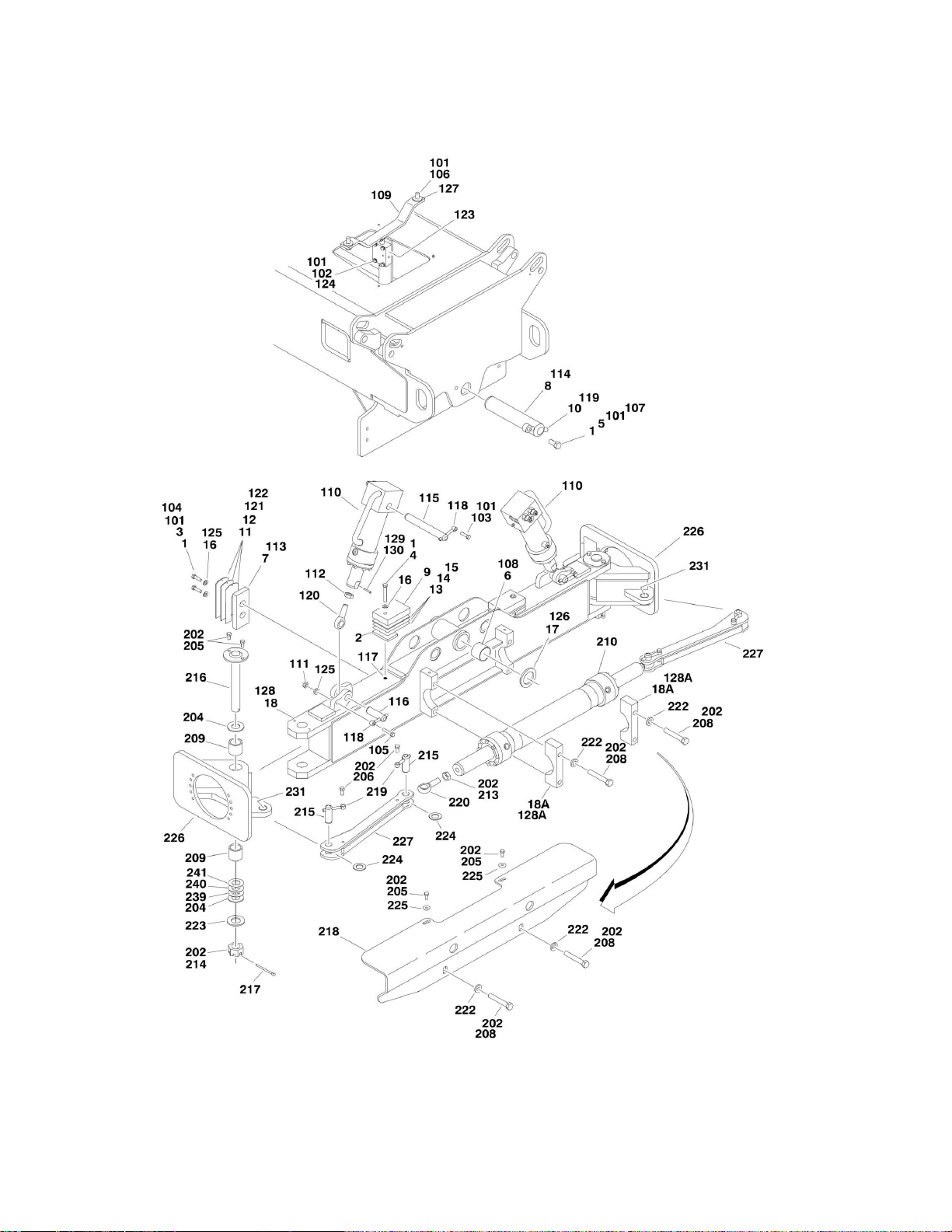
FIGURE 1-1. AXLE AND STEER INSTALLATION - 2WD
10 E600/E600J/E600JP/M600/M600J/M600JP 3121118
Page 11

SECTION 1 - FRAME
ITEM
PART NUMBER
QTY
DESCRIPTION
REV
0259827
Ref
FIXED AXLE INSTALLATION
D 1 0100011
AR
Locking, Compound
2 0362763
2
Bar, Stop
3 0641610
4
Bolt 3/8in-16NC x 1-1/4in
4 0641622
2
Bolt 3/8in-16NC x 2-3/4in
5 0642010
1
Bolt 5/8in-11NC x 1-1/4in
6 0961950
2
Bushing, Garmax
7 3340837
2
Pad, Wear
8 3422592
1
Pin, Axle Pivot
9 Ref
Plate, Stop Options:
9 3570901
2
Plate, Stop (Prior to SN 0300079940)
9 0362954
2
Plate, Stop (SN 0300079940 to Present)
10
3841258
1
Keeper, Pin
11
4070897
4
Shim #18 Ga
12
4070898
2
Shim #11 Ga
13
4070972
1
Shim 3/16in
14
4070973
2
Shim #11 Ga
15
4070974
2
Shim #16 Ga
16
4711600
6
Flatwasher 3/8in Thin
17
4740158
1
Thrustwasher
18
4846077
1
Axle Weldment
18A
0561371
2
Steer Cylinder Mounting Block Assembly
Ref
OSCILLATING AXLE INSTALLATION
0259756
Ref
Without Tow Package
K
0270525
Ref
With Tow Package
F
101
0100019
AR
Locking, Compound
102
0641414
4
Bolt 1/4in-20NC x 1-3/4in
103
0641608
2
Bolt 3/8in-16NC x 1in
104
0641610
4
Bolt 3/8in-16NC x 1-1/4in
105
0641614
2
Bolt 3/8in-16NC x 1-3/4in
106
0641812
2
Bolt 1/2in-13NC x 1-1/2in
107
0642010
1
Bolt 5/8in-11NC x 1-1/4in
108
0961950
2
Bushing, Garmax
109
1100120
1
Cam, Lockout
110
Ref
Lockout Cylinder Assembly Options (See CYLINDER SECTION
for Breakdown):
110
Ref
Without Tow Package
110
1683575
2
Lockout Cylinder Assembly (Prior to SN 0300051263)
110
1683931
2
Lockout Cylinder Assembly (SN 0300051263 through
0300062043)
110
1684071
2
Lockout Cylinder Assembly (SN 0300062044 through
0300064015)
110
1684129
2
Lockout Cylinder Assembly (Use p/n 1684419) (SN
0300064016 through 0300077548)
110
1684419
2
Lockout Cylinder Assembly (SN 0300077549 to Present)
110
Ref
With Tow Package
110
1683931
2
Lockout Cylinder Assembly (Prior to SN 0300062044)
110
1683575
2
Lockout Cylinder Assembly (SN 0300062044 to Present)
112
3311605
2
Locknut 3/8in-16NC
113
3322202
2
Nut, Jam 3/4in-16NF (Prior to SN 0300064016)
FIGURE 1-1. AXLE AND STEER INSTALLATION - 2WD
3121118 E600/E600J/E600JP/M600/M600J/M600JP 11
Page 12

ITEM
PART NUMBER
QTY
DESCRIPTION
REV
114
3340837
2
Pad, Wear
115
3422592
1
Pin, Axle Pivot
116
3422578
2
Pin (Top)
117
3422813
2
Pin (Bottom)
118
3520034
2
Plug, Hole
119
3841143
4
Keeper, Pin
120
3841258
1
Keeper, Pin
121
3841443
2
Rod-End (Prior to SN 0300064016)
122
4070897
4
Shim #18 Ga
123
4070898
2
Shim #11 Ga
124
4640871
1
Lockout Valve Assembly
124
7012693
1
Seal Kit - 4640871 Valve
124
7002840
1
Anti Pin Removal Tool
125
4711400
4
Flatwasher 1/4in Thin
126
4711600
6
Flatwasher 3/8in Thin
127
4740158
1
Thrustwasher
128
4751800
4
Flatwasher 1/2in Regular
129
Ref
Axle Weldment Options:
129
4846077
1
Without Tow Package
129
4846293
1
With Tow Package
129A
0561371
2
Steer Cylinder Mounting Block Assembly
130
0100019
AR
Locking, Compound (SN 0300062044 through 0300064015)
131
3440824
2
Pin, Roll (SN 0300062044 through 0300064016)
Ref
STEERING INSTALLATION
0259755
Ref
Without Tow Package
H
See Note
Ref
With Tow Package (Note: See TOW PACKAGE INSTALLATION
for Breakdown)
201
0100011
AR
Locking, Compound
202
0440162
AR
Thrustwasher
203
0641606
6
Bolt 3/8in-16NC x 3/4in
204
0641607
4
Bolt 3/8in-16NC x 7/8in
205
0642030
4
Bolt 5/8in-11NC x 3-3/4in
206
Ref
Steer Cylinder Assembly (See CYLINDER SECTION for
Breakdown)
206
1683851
1
Steer Cylinder Assembly (Use p/n 1001140281) (Prior to SN
0300165153)
206
1001140281
1
Steer Cylinder Assembly (SN 0300165153 to Present)
207
2780245
2
Hub/Spindle Assembly (See 301 to 311 for Breakdown)
208
3322202
2
Nut, Jam 3/4in-16NF
209
3323003
2
Nut 1-1/4in-12NF
210
3422692
2
Kingpin
211
3422817
4
Pin 212
3450812
2
Pin, Cotter 1/4in x 3in
213
3571709
1
Plate, Steer Cylinder Cover (Prior to SN 0300187512)
214
3841143
4
Keeper, Pin
215
3841443
2
Rod-End
217
4892000
4
Flatwasher,5/8in Hardened
218
4713000
2
Flatwasher 1-1/4in Thin
219
4740111
4
Thrustwasher
220
4751600
2
Flatwasher 3/8in Regular (Prior to SN 0300187512)
221
4846076
2
Tie-Rod
222
1001151395
AR
Shim .048 (SN 0300176747 to Present)
SECTION 1 - FRAME
12 E600/E600J/E600JP/M600/M600J/M600JP 3121118
Page 13

SECTION 1 - FRAME
ITEM
PART NUMBER
QTY
DESCRIPTION
REV
223
1001151428
AR
Shim .036 (SN 0300176747 to Present)
2780245
Ref
HUB ASSEMBLY
C
301
7020137
2
Cap, Dust (1 Per Assembly)
302
7020054
2
Nut, Castle (1 per Assembly)
303
7020140
2
Pin, Cotter (1 per Assembly)
304
7020055
2
Washer, Spindle (1 Per Assembly)
305
7020039
2
Cone, Bearing - Outer (1 per Assembly)
306
7020035
2
Hub (1 Per Assembly)
306A
7020036
2
Cup, Bearing - Inner (1 per Assembly)
306B
7020038
2
Cup, Bearing - Outer (1 per Assembly)
306C
7020041
18
Stud, Wheel (9 Per Assembly)
307
7020037
2
Cone, Bearing - Inner (1 per Assembly)
308
7020040
2
Seal (1 Per Assembly)
309
7020251
2
Spindle Assembly (1 Per Assembly)
310
0961951
4
Bushing, Garmax (2 Per Assembly)
311
0962292
2
Bearing, Garmax (1 Per Assembly)
3121118 E600/E600J/E600JP/M600/M600J/M600JP 13
Page 14
SECTION 1 - FRAME
FIGURE 1-2. AXLE STEERING INSTALLATION - 4WD
14 E600/E600J/E600JP/M600/M600J/M600JP 3121118
Page 15

SECTION 1 - FRAME
ITEM
PART NUMBER
QTY
DESCRIPTION
REV
0270004
Ref
FIXED AXLE INSTALLATION
C 1 0100011
AR
Locking, Compound
2 0362763
2
Bar, Stop
3 0641610
4
Bolt 3/8in-16NC x 1-1/4in
4 0641622
2
Bolt 3/8in-16NC x 2-3/4in
5 0642010
1
Bolt 5/8in-11NC x 1-1/4in
6 0961950
2
Bushing, Garmax
7 3340837
2
Pad, Wear
8 3422592
1
Pin, Axle Pivot
9 Ref
Plate, Stop Options:
9 3570901
2
Plate, Stop (Prior to SN 0300079940)
9 0362954
2
Plate, Stop (SN 0300079940 to Present)
10
3841258
1
Keeper, Pin
11
4070897
4
Shim #18Ga
12
4070898
2
Shim #11Ga
13
4070972
1
Shim 3/16in
14
4070973
2
Shim #11Ga
15
4070974
2
Shim #16Ga
16
4711600
6
Flatwasher 3/8in Thin
17
4740158
1
Thrustwasher
18
4846139
1
Axle Weldment
18A
0561371
2
Steer Cylinder Mounting Block Assembly
0259941
Ref
OSCILLATING AXLE INSTALLATION
J
101
0100011
AR
Locking, Compound
102
0641414
4
Bolt 1/4in-20NC x 1-3/4in
103
0641608
2
Bolt 3/8in-16NC x 1in
104
0641610
4
Bolt 3/8in-16NC x 1-1/4in
105
0641614
2
Bolt 3/8in-16NC x 1-3/4in
106
0641812
2
Bolt 1/2in-13NC x 1-1/2in
107
0642010
1
Bolt 5/8in-11NC x 1-1/4in
108
0961950
2
Bushing, Garmax
109
1100120
1
Cam, Lockout
110
Ref
Lockout Cylinder Assembly Options: (See CYLINDER SECTION
for Breakdown)
110
1683931
2
Lockout Cylinder Assembly (Prior to SN 0300062044)
110
1684071
2
Lockout Cylinder Assembly (SN 0300062044 through
0300064015)
110
1684129
2
Lockout Cylinder Assembly (Use p/n 1684419) (SN 0300064016
through 0300077548)
110
1684419
2
Lockout Cylinder Assembly (SN 0300077549 to Present)
111
3311605
2
Locknut 3/8in-16NC
112
3322202
2
Nut, Jam 3/4in-16NF (Prior to SN 0300064016)
113
3340837
2
Pad, Wear
114
3422592
1
Pin, Axle Pivot
115
3422578
2
Pin (Top)
116
3422813
2
Pin (Bottom)
117
3520034
2
Plug, Hole
118
3841143
4
Keeper, Pin
119
3841258
1
Keeper, Pin
120
3841443
2
Rod-End (Prior to SN 0300064016)
FIGURE 1-2. AXLE STEERING INSTALLATION - 4WD
3121118 E600/E600J/E600JP/M600/M600J/M600JP 15
Page 16

ITEM
PART NUMBER
QTY
DESCRIPTION
REV
121
4070897
4
Shim #18Ga
122
4070898
2
Shim #11Ga
123
4640871
1
Lockout Valve Assembly
123
7012693
1
Seal Kit - 4640871 Valve
123
7002840
1
Anti Pin Removal Tool
124
4711400
4
Flatwasher 1/4in Thin
125
4711600
6
Flatwasher 3/8in Thin
126
4740158
1
Thrustwasher
127
4751800
4
Flatwasher 1/2in Regular
128
4846139
1
Axle Weldment
128A
0561371
2
Steer Cylinder Mounting Block Assembly
129
0100019
AR
Locking, Compound (SN 0300062044 through 0300064016)
130
3440824
4
Pin, Roll (SN 0300062044 through 0300064016)
0259942
Ref
STEERING AND VALVES INSTALLATION
H
202
0100011
AR
Locking, Compound
204
0440161
AR
Thrustwasher
205
0641606
3
Bolt 3/8in-16NC x 3/4in
206
0641607
4
Bolt 3/8in-16NC x 7/8in
208
0642030
4
Bolt 5/8in-11NC x 3-3/4in
209
0961948
4
Bushing, Garmax
210
Ref
Steer Cylinder Assembly (See CYLINDER SECTION for
Breakdown)
210
1683851
1
Steer Cylinder Assembly (Use p/n 1001140281) (Prior to SN
0300165153)
210
1001140281
1
Steer Cylinder Assembly (SN 0300165153 to Present)
213
3322202
2
Nut, Jam 3/4in-16NF
214
3323403
2
Nut, Slotted Castle 1-1/2in-12NF
215
3422817
4
Pin 216
3422819
2
Kingpin
217
3450812
2
Pin, Cotter 1/4in x 3in
218
3571709
1
Plate, Steer Cylinder Cover (Prior to SN 0300187512)
219
3841143
4
Keeper, Pin
220
3841443
2
Rod-End
222
4892000
4
Flatwasher 5/8in Hardened
223
4713400
2
Flatwasher 1-1/2in Thin
224
4740111
4
Thrustwasher
225
4751600
2
Flatwasher 3/8in (Prior to SN 0300187512)
226
4846135
2
Spindle
227
4846141
2
Tie-Rod
231
0962292
2
Bushing
239
1001156428
AR
Shim .120 (SN 0300176747 to Present)
240
1001156429
AR
Shim .060 (SN 0300176747 to Present)
241
1001156430
AR
Shim .030 (SN 0300176747 to Present)
SECTION 1 - FRAME
16 E600/E600J/E600JP/M600/M600J/M600JP 3121118
Page 17

Page 18
SECTION 1 - FRAME
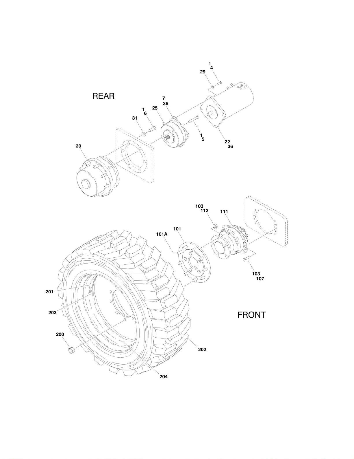
FIGURE 1-3. TIRE AND WHEEL DRIVE INSTALLATIONS
18 E600/E600J/E600JP/M600/M600J/M600JP 3121118
Page 19

SECTION 1 - FRAME
ITEM
PART NUMBER
QTY
DESCRIPTION
REV
Ref
WHEEL DRIVE INSTALLATION - REAR AXLE (2WD & 4WD)
0259741
Ref
ANSI Spec (Prior to SN 0300112387)
E 0274284
Ref
ANSI Spec (SN 0300112387 to Present)
D 0270382
Ref
UL Spec (Prior to SN 0300112387)
C 0274285
Ref
UL Spec (SN 0300112387 to Present)
C 1 0100019
AR
Locking, Compound
4 0641609
8
Bolt 3/8in-16NC x 1-1/8in
5 0641826
4
Bolt 1/2in-13NC x 3-1/4in
6 Ref
Bolt Options:
6 0682011
12
Bolt 5/8in-11NC x 1-3/8in (Grade 8) (Prior to SN 0300112387)
6
0682012
12
Bolt 5/8in-11NC x 1-1/2in (Grade 8) (SN 0300112387 to
Present)
7
0920115
2
Drive Brake Assembly (See DRIVE BRAKE ASSEMBLY (REAR)
for Breakdown)
20 Ref
Drive Hub Assembly Options:
20
2780236
2
Drive Hub Assembly (See DRIVE HUB ASSEMBLY (REAR) for
Breakdown) (Prior to SN 0300112387)
20
2780282
2
Drive Hub Assembly (See DRIVE HUB ASSEMBLY (REAR) for
Breakdown) (SN 0300112387 to Present)
21
3020008
AR
Lubricant, Mobilube HD 80W-90 (Not Shown)
22
3160240
2
Drive Motor Assembly
22
7012545
2
Bearing
22
7012548
AR
Spring, Brush
22
7012547
AR
Brush
25
3990107
2
Sensor, Speed
29
4711600
8
Flatwasher 3/8in Thin
31
4892000
12
Flatwasher 5/8in Hardened
36
3020037
AR
Lube, Coupling Grease
0259942
Ref
WHEEL DRIVE INSTALLATION - FRONT AXLE (4WD ONLY)
G
101
0080233
2
Drive Adapter Assembly
101A
4300145
28
Stud, Wheel (14 Per Assembly)
103
0100019
AR
Locking, Compound
107
0681812
20
Bolt 1/2in-13NC x 3-1/4in (Grade 8)
111
3160251
2
Drive Motor Assembly (See DRIVE MOTOR ASSEMBLY (4WD
FRONT) for Breakdown)
112
3300426
10
Nut, Flanged 5/8in-18NF
Ref
TIRE AND WHEEL INSTALLATIONS
0270061
Ref
36/14LL x 22.5 Foam-Filled Non-Marking (Prior to SN
0300069399)
A
0272694
Ref
36/14LL x 22.5 Foam-Filled Non-Marking (SN 0300069399 to
Present)
B
0270060
Ref
36/14LL x 22.5 Pneumatic Non-Marking (Prior to SN
0300069399)
A
0272695
Ref
36/14LL x 22.5 Pneumatic Non-Marking (SN 0300069399 to
Present)
B
200
3300426
36
Nut, Flanged 5/8in-18NF
0270057
2
36/14LL x 22.5 Foam-Filled Non-Marking (Left Side) (Prior to SN
0300069399)
C
0272693
2
36/14LL x 22.5 Foam-Filled Non-Marking (Left Side) (SN
0300069399 to Present)
D 0270056
2
36/14LL x 22.5 Foam-Filled Non-Marking (Right Side) (Sold As
Assembly Only) (Prior to SN 0300069399)
C
FIGURE 1-3. TIRE AND WHEEL DRIVE INSTALLATIONS
3121118 E600/E600J/E600JP/M600/M600J/M600JP 19
Page 20

ITEM
PART NUMBER
QTY
DESCRIPTION
REV
0272692
2
36/14LL x 22.5 Foam-Filled Non-Marking (Right Side) (Sold As
Assembly Only) (SN 0300069399 to Present)
D
Ref
Note: Assemblies may require ballast/foam filling to
manufacturer's specifications prior to installing on a
machine. Refer to Operation and Safety or Service and
Maintenance Manuals. Purchase individual tire and/or rim
only if able to foam fill tire and wheel assembly, otherwise,
purchase complete assembly.
0270055
2
36/14LL x 22.5 Pneumatic Non-Marking (Left Side) (Prior to SN
0300069399)
C 0272691
2
36/14LL x 22.5 Pneumatic Non-Marking (Left Side) (SN
0300069399 to Present)
C
0270054
2
36/14LL x 22.5 Pneumatic Non-Marking (Right Side) (Prior to
SN 0300069399)
C 0272690
2
36/14LL x 22.5 Pneumatic Non-Marking (Right Side) (SN
0300069399 to Present)
C
201
1702698
1
Decal - 55PSI/4BAR (Pneumatic Only)
202
Ref
Tire, Replacement Options: (36/14LL x 22.5)
202
4520236
1
Non-Marking Tire (Prior to SN 0300069399)
202
4520264
1
Non-Marking Tire (SN 0300069399 to Present)
203
4640113
1
Valve, Air (Pneumatic Only)
204
4860212
1
Rim, Wheel (11.75 x 22.5)
SECTION 1 - FRAME
20 E600/E600J/E600JP/M600/M600J/M600JP 3121118
Page 21

Page 22
SECTION 1 - FRAME
FIGURE 1-4. DRIVE BRAKE ASSEMBLY (REAR)
22 E600/E600J/E600JP/M600/M600J/M600JP 3121118
Page 23

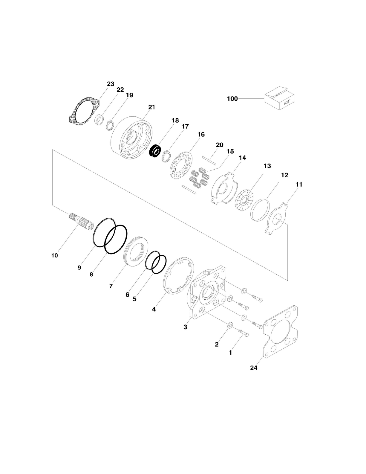
FIGURE 1-4. DRIVE BRAKE ASSEMBLY (REAR)
ITEM
PART NUMBER
QTY
DESCRIPTION
REV
0920115
Ref
DRIVE BRAKE ASSEMBLY
C 1 See Note
4
Bolt (Note: Not Available for Purchase)
2 See Note
4
Flatwasher (Note: Not Available for Purchase)
3 0920115
1
Plate, Pressure (Note: Not Available for Purchase)
4 7011757
1
Seal, Case
5 7011757
1
O-Ring 6
7011757
1
Ring, Back-up
7 0920115
1
Piston (Note: Not Available for Purchase)
8 7011757
1
O-Ring 9
7011757
1
Ring, Back-up
10
0920115
1
Shaft 11
7011757
1
Stator
12
See Note
1
Ring, Sensor (Note: Not all models use sensor ring) (was p/n
7027275 which is No Longer Available. Replace Complete Brake.)
13
7011757
1
Rotor 14
7011757
1
Plate, Return
15
7011757
AR
Spring 16
0920115
1
Guide, Spring (Note: Not Available for Purchase)
17
0920115
1
Ring, Retaining (Note: Not Available for Purchase)
18
7011757
1
Bearing
19
See Note
1
Ring, Retainer (Note: Not Available for Purchase)
20
See Note
2
Pin, Dowel (Note: Not Available for Purchase)
21
0920115
1
Cover (Note: Not Available for Purchase)
22
7007900
1
Seal, Oil
23
7007933
1
Gasket
24
70002408
1
Gasket
100
7011757
1
Seal Kit (Includes Items 4, 5, 6, 8, 9, 11, 13, 14, 15, 18, 22 & 23)
SECTION 1 - FRAME
3121118 E600/E600J/E600JP/M600/M600J/M600JP 23
Page 24
SECTION 1 - FRAME
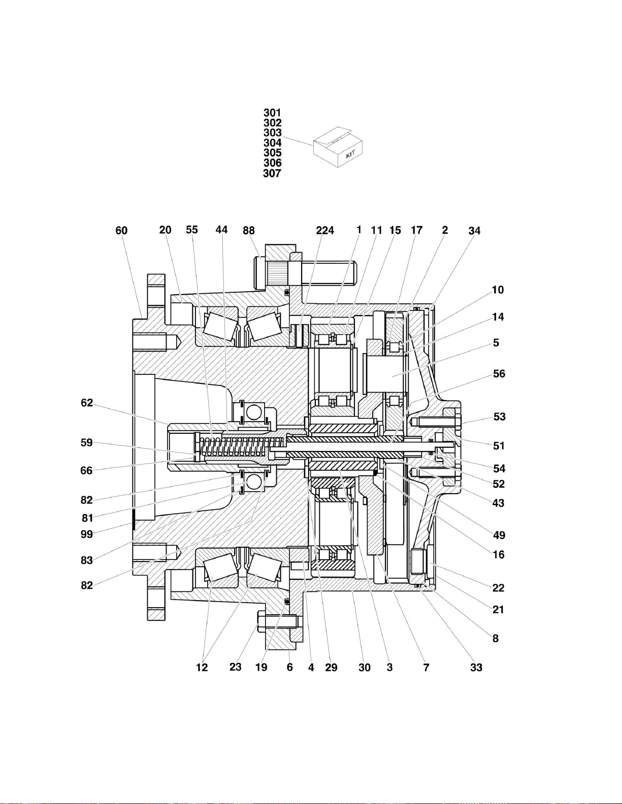
FIGURE 1-5. DRIVE HUB ASSEMBLY (REAR) (Prior to SN 0300112387)
24 E600/E600J/E600JP/M600/M600J/M600JP 3121118
Page 25

SECTION 1 - FRAME
ITEM
PART NUMBER
QTY
DESCRIPTION
REV
2780236
Ref
DRIVE HUB ASSEMBLY
E 1 7021323
4
Gear, Planet
2 7021324
3
Gear, Planet
3 7021325
1
Gear, Sun
4 7023803
1
Nut, Shaft
Ref
NOTE: Unless there is capability to torque shaft nut (item 4) to
625 ft/lbs. (850Nm) Repair beyond this level is NOT advised.
5
7021326
3
Bolt, Planet
6 7021327
1
Ring, Support
7 7021328
1
Carrier, Planet
8 70003711
1
Cover 10
70003712
3
Bearing, Roller
11
70003713
4
Bearing, Roller
12
70003714
2
Bearing, Roller
14
70003715
3
Ring, Retaining
15
70003716
4
Ring, Retaining
16
7021341
1
Ring, Retaining
17
70003717
3
Disk, Support
19
See Note
1
O-Ring (Note: Use Item 303 or 307)
20
See Note
1
Seal, Ring (Note: Use Item 303 or 307)
21
See Note
3
Plug (Note: Use Item 304 or 307)
22
See Note
3
Seal, Ring (Note: Use Item 304 or 307)
23
7021342
3
Bolt 29
7024049
1
Thrustwasher
30
7021335
1
Gear, Ring
33
See Note
1
O-Ring (Note: Use Item 303, 304 or 307)
34
70003718
1
Ring, Retaining
43
7021336
1
Shaft, Sun Gear
44
7021337
1
Shaft, Input
49
7024051
1
Thrustwasher
51
70003719
1
Cover 52
70003720
1
Disk 53
70003721
2
Bolt (Note: Use Item 304, 305 or 306)
54
See Note
1
O-Ring (Note: Use Item 304, 305, 306 or 307)
55
7024053
1
Spring, Pressure
56
70003722
1
Rod, Shaft (Note: Use Item 305 or 306)
59
70003723
1
Disk, Rotor
60
7021339
1
Spindle
62
7021340
1
Coupler
66
70003724
1
Ring, Retaining
81
7024983
1
Bearing, Ball
82
7021341
2
Ring, Retaining
83
7024931
1
Ring, Retaining
88
7021344
9
Stud, Wheel (was p/n 7024984)
99
7024985
1
Plug 224
Ref
Component Options:
224
7024047
NLA
Ball (Note: No Longer Available) (Prior to SN 0300089408)
224
7024047
NLA
Expander (Note: No Longer Available) (Prior to SN 0300089408)
224
7024047
NLA
Plug (Note: No Longer Available) (Prior to SN 0300089408)
224
70003725
2
Pin, Slotted (SN 0300089408 to Present)
FIGURE 1-5. DRIVE HUB ASSEMBLY (REAR) (Prior to SN 0300112387)
3121118 E600/E600J/E600JP/M600/M600J/M600JP 25
Page 26

ITEM
PART NUMBER
QTY
DESCRIPTION
REV
Ref
Kit Options:
301
7024981
1
Planet Gear Kit 1 (Includes Items 1, 11 & 15)
302
7024986
1
Planet Gear Kit 2 (Includes Items 2, 10,14 & 17)
303
7024047
1
Bearing Kit (Includes Items 4, 12, 19, 20, 23, 33 & 224)
Ref
NOTE: Unless there is capability to torque shaft nut (item 4)
to 625 ft/lbs. (850Nm) Repair beyond this level is NOT
advised.
304
7021329
1
Cover Kit (Includes Items 8, 21, 22, 33, 34 & 51-54)
305
7021338
1
Mechanical Disconnect Kit 1(Includes Items 54-56, 59 & 66)
306
7024054
1
Mechanical Disconnect Kit 2 (Includes Items 51, 53, 54 & 56)
307
7021333
1
Seal Kit (Includes Items 19-22, 33 & 54)
SECTION 1 - FRAME
26 E600/E600J/E600JP/M600/M600J/M600JP 3121118
Page 27

Page 28
SECTION 1 - FRAME
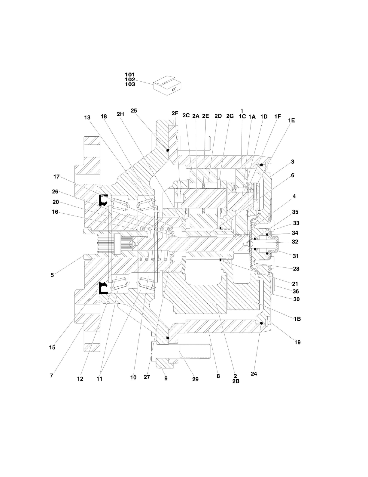
FIGURE 1-6. DRIVE HUB ASSEMBLY (REAR) (SN 0300112387 to Present)
28 E600/E600J/E600JP/M600/M600J/M600JP 3121118
Page 29

SECTION 1 - FRAME
ITEM
PART NUMBER
QTY
DESCRIPTION
REV
2780282
Ref
DRIVE HUB ASSEMBLY
B 1 70001366
1
Carrier, Sub Assembly (Purchase p/n 70001366 for items 1A-1F)
1A
70001366
3
Shaft, Planet (Note: Not Available for Purchase)
1B
70001366
1
Carrier (Note: Not Available for Purchase)
1C
70001366
3
Gear, Planet (Note: Not Available for Purchase)
1D
70001366
42
Bearing, Needle (Note: Not Available for Purchase)
1E
70001366
3
Pin, Roll (Note: Not Available for Purchase)
1F
70001366
6
Thrustwasher (Note: Not Available for Purchase)
2 70001367
1
Carrier, Input (Purchase p/n 70001367 for items 2A-2H)
2A
70001367
3
Shaft, Planet (Note: Not Available for Purchase)
2B
70001367
1
Carrier (Note: Not Available for Purchase)
2C
70001367
3
Gear, Planet (Note: Not Available for Purchase)
2D
70001367
84
Bearing, Needle (Note: Not Available for Purchase)
2E
70001367
3
Spacer, Thrust (Note: Not Available for Purchase)
2F
70001367
3
Pin, Roll (Note: Not Available for Purchase)
2G
70001367
12
Thrustwasher (Note: Not Available for Purchase)
2H
70001367
1
Thrustwasher (Note: Not Available for Purchase)
3 70001368
1
Cover 4
70001369
1
Shaft, Input
5 70001370
1
Coupling
6 70001371
1
Shaft, Sun Gear
7 70001372
1
Spindle 8
70001373
1
Gear, Ring
9 2780282
1
Housing (Note: Not Available for Purchase)
10
7017007
1
Bearing, Tapered-Cone
11
7017007
2
Bearing, Tapered-Cup
12
7017007
1
Bearing, Tapered-Cone
13
7017009
1
Thrustwasher
15
70001380
1
Seal, Lip
16
70001374
1
Spring 17
70001375
1
Ring, Retaining (Internal)
18
70001380
1
Ring, Retaining (External)
19
7024738
1
Ring, Retaining (Internal)
20
70001376
1
Ring, Retaining (External)
21
70001377
1
Ring, Retaining (External)
22
7000281
4
Screw (Not Shown - ID plate screws)
23
7017022
3
Bolt, Flathead (Not Shown - Located on front of hub)
24
70001380
1
O-Ring 25
70001380
1
O-Ring 26
70001378
1
Spacer, Thrust
27
70001379
1
Thrustwasher
28
7024741
1
Spacer, Thrust
29
7007640
9
Stud, Wheel
30
70001368
1
Flange, Plate
31
70001368
1
Cap, Disengage
32
70001368
1
Pin, Dowel
33
70001368
2
Bolt 34
70001368
1
O-Ring 35
70001368
1
O-Ring 36
70001368
1
Plug
FIGURE 1-6. DRIVE HUB ASSEMBLY (REAR) (SN 0300112387 to Present)
3121118 E600/E600J/E600JP/M600/M600J/M600JP 29
Page 30

ITEM
PART NUMBER
QTY
DESCRIPTION
REV
Ref
Kit Options:
101
7017007
1
Planet Gear Kit 1 (Includes Items 10-12)
102
70001380
1
Planet Gear Kit 2 (Includes Items 15, 18, 24 & 25)
103
70001368
1
Bearing Kit (Includes Items 30-36)
SECTION 1 - FRAME
30 E600/E600J/E600JP/M600/M600J/M600JP 3121118
Page 31

Page 32

SECTION 1 - FRAME
FIGURE 1-7. DRIVE MOTOR ASSEMBLY (4WD FRONT)
32 E600/E600J/E600JP/M600/M600J/M600JP 3121118
Page 33

SECTION 1 - FRAME
ITEM
PART NUMBER
QTY
DESCRIPTION
REV
3160251
Ref
DRIVE MOTOR ASSEMBLY
B
1
See Note
1
Housing Assembly (Front) (Note: Not Available - Use 3160251 for
complete replacement. See 101-108 for available components.)
2
7023866
1
Rotary Group Assembly
2A
7023869
1
Rotary Group HD w/o Cam
2B
7023870
1
Cam
3
See Note
1
Housing Assembly (Rear) (Note: Not Available - Use 3160251 for
complete replacement. See 201-208A for available components.)
4
7023801
2
Seal, Square
5 7023876
6
Screw, Cap
9 7023806
5
Lugnut 10
7023807
5
Stud 16
7023801
1
Seal, Square
17
7023801
1
Plate, Rear Cover
18
7023868
8
Screw, Cap
Ref
HOUSING ASSEMBLY (FRONT)
101
7022586
1
Shaft 102
7023801
1
Seal, Face
103
7022587
1
Bearing, Front
104
3160251
1
Casting, Front (Note: Not Available for Purchase)
105
7023801
1
Seal, Shaft
106
7022588
1
Bearing, Rear
107
Ref
Washer Options:
107
See Note
1
Washer (1.50mm) (Note: Not Available for Purchase)
107
See Note
1
Washer (1.65mm) (Note: Not Available for Purchase)
107
See Note
1
Washer (1.85mm) (Note: Not Available for Purchase)
107
See Note
1
Washer (2.00mm) (Note: Not Available for Purchase)
107
See Note
1
Washer (2.15mm) (Note: Not Available for Purchase)
107
See Note
1
Washer (2.35mm) (Note: Not Available for Purchase)
108
7022589
1
Ring, Split
Ref
HOUSING ASSEMBLY (REAR)
201
7023871
1
Ring, Distributor
202
7023872
9
Spring
203
7023801
1
Seal 204
7023801
1
Seal 205
7023801
1
Seal 206
See Note
1
Housing, Rear (Note: Not Available for Purchase)
207
See Note
1
Pin, Stop (Note: Not Available for Purchase)
208
7022591
1
Plug 208A
See Note
1
O-Ring (Note: Not Available for Purchase)
Ref
KIT OPTIONS:
300
7023801
1
Seal Kit (Includes Items - 4,16,17,102,105 & 203 thru 205)
FIGURE 1-7. DRIVE MOTOR ASSEMBLY (4WD FRONT)
3121118 E600/E600J/E600JP/M600/M600J/M600JP 33
Page 34

SECTION 1 - FRAME
FIGURE 1-8. VALVES, ELECTRICAL COMPONENTS AND SHIELDS INSTALLATIONS
34 E600/E600J/E600JP/M600/M600J/M600JP 3121118
Page 35

SECTION 1 - FRAME
ITEM
PART NUMBER
QTY
DESCRIPTION
REV
0259942
Ref
4WD VALVES INSTALLATIONS
G
Ref
Note: See AXLE AND STEER INSTALLATION - 2WD AND
AXLE AND STEER INSTALLATION - 4WD for Oscillating Axle
Lockout Valve.
2
0100011
AR
Locking, Compound
29
0641404
4
Bolt 1/4inin-20NC x 1/2in
30
0641504
8
Bolt 5/16in-18NC x 1/2in
32
3572328
1
Plate, Mounting
33 Ref
Valve Assembly - Drive (See DRIVE VALVE ASSEMBLY (4WD
ONLY) for Breakdown)
33
4641127
1
Valve Assembly (Use p/n 1001092586) (Prior to SN
0300102660)
33
1001092586
1
Valve Assembly (SN 0300102660 to Present)
34
4641148
1
Flow Divider Assembly
34
See Note
1
Seal Kit - 4641148 Valve (Note: Not Available for Purchase)
35
4711400
4
Flatwasher 1/4in Thin
36
4711500
4
Flatwasher 5/16in Thin
37
4751500
4
Flatwasher 5/16in Regular
38
4922323
1
Harness, 4WD (Not Shown - See ELECTRICAL SECTION for
Breakdown)
Ref
ELECTRICAL COMPONENTS INSTALLATION
0259741
Ref
ANSI Spec (Prior to SN 0300112387)
E 0274284
Ref
ANSI Spec (SN 0300112387 to Present)
D 0270382
Ref
UL Spec (Prior to SN 0300112387)
C 0274285
Ref
UL Spec (SN 0300112387 to Present)
C
101
0100011
AR
Locking, Compound
103
0340047
2
Band, Motor (UL Spec Only)
104
0641506
10
Bolt 5/16in-18NC x 3/4in
105
0641604
1
Bolt 3/8in-16NC x 1/2in
109
0721005
4
Screw (UL Spec Only)
110
0861375
1
Cover, Box (UL Spec Only)
122
1600293
1
Module, Positrac/Tilt (Note: Calibration required when replaced)
123
Ref
Contactor Panel Assembly Options: (See Items 301-303 for
Breakdown)
123
1600294
1
ANSI Spec
123
1600300
1
UL Spec
124
1600302
1
Controller, Power Module
125
1704712
1
Decal - 300Amp Fuse (UL Spec Only)
126
2400044
1
Block, Fuse Mounting (UL Spec Only)
127
2400062
1
Fuse, 300Amp (UL Spec Only)
128
2540037
2
Grommet, Fuse Box (UL Spec Only)
132
3310601
4
Nut 5/16in-18NC
133
3311001
2
Nut #10-24NC (UL Spec Only)
134
3311501
2
Nut 5/16in-18NC (UL Spec Only)
135
3910636
4
Bolt #6-32NCx 2-1/4in
137
4060808
15
in/37cm
Flex-Trim (ANSI Spec)
137
4060807
15
in/37cm
Flex-Trim (UL Spec)
138
4240084
1
Strap, Static
139
4711500
10
Flatwasher 5/16in Thin
FIGURE 1-8. VALVES, ELECTRICAL COMPONENTS AND SHIELDS INSTALLATIONS
3121118 E600/E600J/E600JP/M600/M600J/M600JP 35
Page 36

ITEM
PART NUMBER
QTY
DESCRIPTION
REV
141
4750600
4
Flatwasher #6 Regular
142
4751000
6
Flatwasher #10 Regular (UL Spec Only)
143
4751600
1
Flatwasher 3/8in Regular
146
0840041
1
Boot, Battery Cable (UL Spec Only)
0259836
Ref
FRAME SHIELDS INSTALLATION
F
201
0100011
AR
Locking, Compound
202
0641505
12
Bolt 5/16in-18NC x 5/8in
203
2940042
1
Latch 204
3311501
3
Nut 5/16in-18NC
205
3520064
2
Plug 206
3571797
2
Cover, Axle
207
3572055
1
Cover, Front Frame
208
3960447
4 ft/1.2m
Seal, Self-Gripping
209
4751500
15
Flatwasher 5/16in Regular
210
4846161
1
Door Weldment
211
1060799
1
Cable, Lanyard
212
3311601
2
Nut 3/8in-16NC
213
0641608
1
Bolt 3/8in-16NC x 1in
214
3900283
1
Screw, Button Head 1/4in x 3/4in
215
4711400
3
Flatwasher 1/4in Thin
Ref
CONTACTOR PLATE ASSEMBLY
1600294
Ref
ANSI Spec
E 1600300
Ref
UL Spec
B
Ref
Note: Torque Bolts to 80in lbs replacing components.
Ref
Contactor Harness Options: (See ELECTRICAL SECTION for
Breakdown)
7022003
1
ANSI Spec
7022008
1
UL Spec
Ref
Posi -Track Contactor Harness Options: (See ELECTRICAL
SECTION for Breakdown)
7022004
1
ANSI Spec
Not Required
0
UL Spec
7022005
1
Harness, Shunt (See ELECTRICAL SECTION for Breakdown)
301
Ref
Contactor Options: (Fwd/Rev)
301
7022002
1
ANSI Spec
301
7022007
1
UL Spec
302
Ref
Contactor Options: (Main)
302
7022001
1
ANSI Spec
302
7022009
1
UL Spec
303
Ref
Contactor Options: (Posi-Track)
303
7022000
1
ANSI Spec
303
7022010
1
UL Spec
SECTION 1 - FRAME
36 E600/E600J/E600JP/M600/M600J/M600JP 3121118
Page 37

Page 38

SECTION 1 - FRAME
FIGURE 1-9. DRIVE VALVE ASSEMBLY (4WD ONLY)
38 E600/E600J/E600JP/M600/M600J/M600JP 3121118
Page 39

SECTION 1 - FRAME
ITEM
PART NUMBER
QTY
DESCRIPTION
REV
Ref
DRIVE VALVE ASSEMBLY
4641127
Ref
Drive Valve Assembly (Prior to SN 0300102660)
D 1001092586
Ref
Drive Valve Assembly (SN 0300102660 to Present)
A 2
Ref
Manifold Options:
2 See Note
1
4641127 Valve (Note: Not Available for Purchase)
2 1001092586
1
1001092586 Valve
3 Ref
Control Valve Assembly Options:
3 7024011
1
4641127 Valve
3 70001422
1
1001092586 Valve
3 7012773
1
Seal Kit - 4641127 & 1001092586 Valve
3A
7021375
2
Nut
3B Ref
Coil Options:
3B
7024013
2
4641127 Valve
3B
70002947
2
1001092586 Valve
3C
7012799
1
Lanyard (4641127 Valve) (Prior to SN 0300058444)
4 Ref
Control Valve Assembly Options:
4 7024011
1
4641127 Valve
4 70001422
1
1001092586 Valve
4 7012773
1
Seal Kit - 4641127 & 1001092586 Valve
4A
7021375
2
Nut
4B Ref
Coil Options:
4B
7024013
2
4641127 Valve
4B
70002947
2
1001092586 Valve
4C
7012799
1
Lanyard (4641127 Valve) (Prior to SN 0300058444)
5
7012969
1
Cartridge, Check
5
7012540
1
Seal Kit - 7012969 Valve
6
7012969
1
Cartridge, Check
6 7012540
1
Seal Kit - 7012969 Valve
7 7012969
1
Cartridge, Check
7 7012540
1
Seal Kit - 7012969 Valve
8 7012969
1
Cartridge, Check
8 7012540
1
Seal Kit - 7012969 Valve
9 7018942
8
Capscrew #10-24NC x 2in
FIGURE 1-9. DRIVE VALVE ASSEMBLY (4WD ONLY)
3121118 E600/E600J/E600JP/M600/M600J/M600JP 39
Page 40

SECTION 1 - FRAME
FIGURE 1-10. TOW PACKAGE INSTALLATION
40 E600/E600J/E600JP/M600/M600J/M600JP 3121118
Page 41

FIGURE 1-10. TOW PACKAGE INSTALLATION
ITEM
PART NUMBER
QTY
DESCRIPTION
REV
0270527
Ref
TOW PACKAGE INSTALLATION
A 1 0100011
AR
Locking, Compound
2 0270528
1
Tow Bar Assembly (See Items 101 to 121 for Breakdown)
3 0641504
2
Bolt 5/16in-18NC x 1/2in
4 3572506
1
Plate, Valve Mounting
5 4640261
1
Valve, Tow
6 4711500
2
Flatwasher 5/16in Thin
0270528
Ref
TOW BAR ASSEMBLY
A
101
0100011
AR
Locking, Compound
102
0362910
1
Pintle, Draw Eye
103
0642010
4
Bolt 5/8in-11NC x 1-1/4in
104
0721004
2
Screw, Hex Machine
105
0741607
24
Screw, Countersunk 3/8in-16NC x 7/8in
106
1060584
6
Cable, Lanyard
107
3420372
2
Pin, Cotter
108
3420447
1
Pin, Towing
109
3421565
2
Pin, Snap
110
3422841
2
Pin 111
3422847
1
Pin 112
3572009
2
Plate, Slide Stop
113
3572010
2
Plate, Slide Stop
114
3572011
2
Plate, Slide Stop
115
3572012
2
Plate, Slide Stop
116
3760170
8
Ring, Split
117
4568133
1
Tube, Tow Bar
118
4740036
1
Flatwasher, Special
119
4751000
2
Flatwasher #10 Regular
120
4846295
1
Tow Bar Attach Weldment
121
4846296
1
Pintle Attach Weldment
0270526
Ref
STEERING WITH TOW PACKAGE INSTALLATION (2WD)
E
201
0100011
AR
Locking, Compound
202
0100019
AR
Locking, Compound
203
0440162
AR
Thrustwasher
204
0641606
3
Bolt 3/8in-16NC x 3/4in
205
0641607
4
Bolt 3/8in-16NC x 7/8in
206
0641608
1
Bolt 3/8in-16NC x 1in
207
0642030
4
Bolt 5/8in-11NC x 3-3/4in
208
0962292
4
Bushing, Garmax
209
0962348
1
Bushing, Composite
210
Ref
Steer Cylinder Assembly (See CYLINDER SECTION for
Breakdown)
210
1683851
1
Steer Cylinder Assembly (Use p/n 1001140281) (Prior to SN
0300165153)
210
1001140281
1
Steer Cylinder Assembly (SN 0300165153 to Present)
211
2780245
2
Hub/Spindle Assembly (See 301 to 311 for Breakdown)
212
3322202
2
Nut, Jam 3/4in-16NF
213
3323003
2
Nut 1-1/4in-12NF
214
3422692
2
Kingpin
215
3422817
4
Pin 216
3422848
1
Pin, Hitch
SECTION 1 - FRAME
3121118 E600/E600J/E600JP/M600/M600J/M600JP 41
Page 42

ITEM
PART NUMBER
QTY
DESCRIPTION
REV
217
3450812
2
Pin, Cotter 1/4in x 3in
218
3571709
1
Plate, Steer Cylinder Cover (Prior to SN 0300187512)
219
3572490
1
Plate, Tow Bar Pivot
220
3841143
5
Keeper, Pin
221
3841443
2
Rod-End
222
3900295
1
Bolt, Shoulder 1in x 3in
223
3900296
1
Bolt, Shoulder 1in x 4-1/2in
225
4713000
2
Flatwasher 1-1/4in Thin
226
4740111
9
Thrustwasher
227
4740155
2
Thrustwasher
228
4751600
2
Flatwasher 3/8in Regular (Prior to SN 0300187512)
229
4846076
1
Tie-Rod (Left Side)
230
4846294
1
Tie-Rod (Right Side)
231
4846294
1
Link, Tow Bar
232
4892000
4
Flatwasher 5/8in Hardened
233
1001151395
AR
Shim .048 (SN 0300176747 to Present)
234
1001151428
AR
Shim .036 (SN 0300176747 to Present)
2780245
Ref
HUB ASSEMBLY
C
301
7020137
2
Cap, Dust (1 Per Assembly)
302
7020054
2
Nut, Castle (1 per Assembly)
303
7020140
2
Pin, Cotter (1 per Assembly)
304
7020055
2
Washer, Spindle (1 Per Assembly)
305
7020039
2
Cone, Bearing - Outer (1 per Assembly)
306
7020035
2
Hub (1 Per Assembly)
306A
7020036
2
Cup, Bearing - Inner(1 per Assembly)
306B
7020038
2
Cup, Bearing - Outer (1 per Assembly)
306C
7020041
18
Stud, Wheel (9 Per Assembly)
307
7020037
2
Cone, Bearing - Inner (1 per Assembly)
308
7020040
2
Seal (1 Per Assembly)
309
7020251
2
Spindle Assembly (1 Per Assembly)
310
0961951
4
Bushing, Garmax (2 Per Assembly)
311
0962292
2
Bearing, Garmax (1 Per Assembly)
Ref
TOW DECALS INSTALLATION
0270629
Ref
English Language
A 0270631
Ref
English/Spanish Combination
A
401
Ref
Decal - Warning Options:
401
1703450
1
English Language
401
1704576
1
English/Spanish Combination
402
Ref
Decal - Tow Instructions Options:
402
1704482
1
English Language
402
1704457
1
English/Spanish Combination
403
Ref
Decal - Crushing Options:
403
1704578
3
English Language
403
1704577
3
English/Spanish Combination
404
Ref
Nameplate - Steer/Tow Select Options:
404
3250872
1
English Language
404
3252693
1
English/Spanish Combination
405
3820001
4
Rivet
406
4420051
35
in/89cm
Tape, Safety
SECTION 1 - FRAME
42 E600/E600J/E600JP/M600/M600J/M600JP 3121118
Page 43

SECTION 2 - TURNTABLE
SECTION 2 - TURNTABLE
3121118 E600/E600J/E600JP/M600/M600J/M600JP 43
Page 44

SECTION 2 - TURNTABLE
FIGURE 2-1. VALVE AND HORN INSTALLATIONS
44 E600/E600J/E600JP/M600/M600J/M600JP 3121118
Page 45

SECTION 2 - TURNTABLE
ITEM
PART NUMBER
QTY
DESCRIPTION
REV
Ref
VALVE AND HORN INSTALLATIONS
0270096
Ref
Valve and Horn Installations E600 & M600
G 0270097
Ref
Valve and Horn Installations E600J & M600J
G 0270098
Ref
Valve and Horn Installations E600JP & M600JP
G 1 0100011
AR
Locking, Compound
2 0140028
1
Horn 3
0641507
1
Bolt 5/16in-18NC x 7/8in
4 0641606
6
Bolt 3/8in-16NC x 3/4in
6 0741005
2
Bolt #10-24NC x 5/8in
7 1320070
1
Clamp 8
1380136
2
Clip 10
3311005
2
Locknut #10-24NC
11
3311505
1
Locknut 5/16in-18NC
13
3900283
7
Screw, Button Head
15
4641123
1
Main Control Valve Assembly (Use p/n 1001092566) (See MAIN
CONTROL VALVE ASSEMBLY for Breakdown)
15
4641235
1
Main Control Valve Assembly (Use p/n 1001092566) (See MAIN
CONTROL VALVE ASSEMBLY for Breakdown)
18
4711500
8
Flatwasher 5/16in Thin
19
4711600
13
Flatwasher 3/8in Thin
21
4751000
4
Flatwasher #10 Regular
22
4846183
1
Tray Weldment
FIGURE 2-1. VALVE AND HORN INSTALLATIONS
3121118 E600/E600J/E600JP/M600/M600J/M600JP 45
Page 46

SECTION 2 - TURNTABLE
FIGURE 2-2. MAIN CONTROL VALVE ASSEMBLY
46 E600/E600J/E600JP/M600/M600J/M600JP 3121118
Page 47

SECTION 2 - TURNTABLE
ITEM
PART NUMBER
QTY
DESCRIPTION
REV
Ref
MAIN CONTROL VALVE ASSEMBLY
4641123
Ref
Main Control Valve Assembly (Prior to SN 0300065648)
C
4641235
Ref
Main Control Valve Assembly (SN 0300065648 through
0300102659)
B
1001092566
Ref
Main Control Valve Assembly (SN 0300102660 to Present)
E
Ref
Note: Valve Assembly p/n 7024019 no Longer Available,
Purchase p/n 70001342 for Complete Replacement
1
See Note
1
Block (Note: Not Available for Purchase)
2 7012912
1
Cartridge, Relief (Main)
2 7012998
1
Seal Kit - 7012912 Cartridge
3 7021619
1
Cartridge, Pressure Switch (Brake)
4 Ref
Cartridge without Coil Options: (Brake)
4 7017455
1
Cartridge without Coil (Prior to SN 0300058444)
4 7012941
1
Cartridge without Coil (SN 0300058444 to Present)
4 Ref
Seal Kit Options:
4 7017463
1
Seal Kit (7017455 Cartridge) (Prior to SN 0300058444)
4 7010543
1
Seal Kit (7012941 Cartridge) (SN 0300058444 to Present)
4 Ref
Coil Options:
4 7012943
1
Coil (7017455 Cartridge) (Prior to SN 0300058444)
4 7012944
1
Coil (7012941 Cartridge) (SN 0300058444 to Present)
5 7012975
1
Cartridge, Check (Telescope Out)
5 7012967
1
Seal Kit - 7012975 Cartridge
6 7018900
1
Orifice 7 Ref
Cartridge, Check Options: (Telescope In)
7 7012969
1
Cartridge, Check (Prior to SN 0300058444)
7 7017412
1
Cartridge, Check (SN 0300058444 through 0300065647)
7 7022391
1
Cartridge, Check (SN 0300065648 to Present)
7 7012967
1
Seal Kit - 7012969, 7017412 & 7022391 Cartridge
8 Ref
Control Valve Assembly (Telescope)
8 7024018
1
Control Valve Assembly (Prior to SN 0300102660)
8 70001440
1
Control Valve Assembly (SN 0300102660 to Present)
8 7012773
1
Seal Kit
8A Ref
Coil Options:
8A
7024013
2
Coil (Prior to SN 0300102660)
8A
70002947
2
Coil (SN 0300102660 to Present)
8A
7021375
Ref
Nut Options:
8A
7021375
2
Nut (Prior to SN 0300102660)
8A
7021375
1
Nut (SN 0300102660 to Present)
8B
70003525
1
Nut (SN 0300102660 to Present)
8C Ref
Lanyard Options:
8C
7012799
1
Lanyard (Prior to SN 0300102660)
8C
70003526
1
Lanyard (SN 0300102660 to Present)
9 7012912
1
Cartridge, Relief (Flow Control)
9 7012998
1
Seal Kit - 7012912 Cartridge
10
7012912
1
Cartridge, Relief (Steer)
10
7012998
1
Seal Kit - 7012912 Cartridge
11
7010542
1
Cartridge, Load Shuttle (Steer)
11
7010543
1
Seal Kit - 7010542 Cartridge
12 Ref
Control Valve Assembly (Steer) Options:
12
7021365
1
Control Valve Assembly (Prior to SN 0300058444)
FIGURE 2-2. MAIN CONTROL VALVE ASSEMBLY
3121118 E600/E600J/E600JP/M600/M600J/M600JP 47
Page 48

ITEM
PART NUMBER
QTY
DESCRIPTION
REV
12
70001342
1
Control Valve Assembly (Note: Valve Assembly p/n 7024019 no
Longer Available, Purchase p/n 70001342 for Complete
Replacement) (SN 0300058444 through 0300102659)
12
70001342
1
Control Valve Assembly (SN 0300102660 to Present)
12
7012773
1
Seal Kit
12A
Ref
Coil Options:
12A
7021376
2
Coil (Prior to SN 0300058444)
12A
7024013
2
Coil (SN 0300058444 through 0300102659)
12A
70002947
2
Coil (SN 0300102660 to Present)
12A
7021375
2
Nut
13
7022521
1
Control Valve Assembly (Flow Control)
13
7012773
1
Seal Kit
13A
7018991
1
Coil
13A
7021375
1
Nut
14 Ref
Control Valve Assembly Options: (Lift)
14
7012775
1
Control Valve Assembly (Prior to SN 0300065648)
14
See Note
1
Control Valve Assembly (Note: Not Available for Purchase) (SN
0300065648 to Present)
14
7012773
1
Seal Kit (Prior to SN 0300065648)
14A
7018991
2
Coil (Prior to SN 0300065648)
14A
7018912
2
Nut (Prior to SN 0300065648)
14A
7012912
1
Cartridge, Relief (Swing)
15
7012998
1
Seal Kit - 7012912 Cartridge
15
7010542
1
Cartridge, Load Shuttle (Swing)
16
7010543
1
Seal Kit - 7010542 Cartridge
16 Ref
Control Valve Assembly (Swing) Options:
17
See Note
1
Control Valve Assembly (Note: Not Available for Purchase)
(Prior to SN 0300058444)
17
7024020
1
Control Valve Assembly (Swing) (SN 0300058444 to Present)
17 Ref
Seal Kit Options:
17
See Note
1
Seal Kit (Note: Not Available for Purchase) (Prior to SN
0300058444)
17
7024021
1
Seal Kit (SN 0300058444 to Present)
17 Ref
Coil Options:
17A
See Note
1
Coil (Note: Not Available for Purchase) (Prior to SN
0300058444)
17A
7018991
2
Coil (SN 0300058444 to Present)
17A
7021375
2
Nut
17A
7012799
2
Lanyard
17A
4641129
1
Cartridge, Check (Swing)
18
7012967
1
Seal Kit - 4641129 Cartridge
18
4641129
1
Cartridge, Check (Swing)
19
7012967
1
Seal Kit - 4641129 Cartridge
19 Ref
Control Valve Assembly (Manual Descent) Options:
20
7018901
1
Control Valve Assembly (Manual (Prior to SN 0300058444)
20
7024022
1
Control Valve Assembly (Manual (SN 0300058444 to Present)
20 Ref
Seal Kit Options:
20
7022531
1
Seal Kit (Prior to SN 0300058444)
20
7024024
1
Seal Kit (SN 0300058444 to Present)
20A
Ref
Handle Options:
20A
See Note
1
Handle (Note: Not Available for Purchase) (Prior to SN
0300058444)
20A
7024023
1
Handle (SN 0300058444 to Present)
SECTION 2 - TURNTABLE
48 E600/E600J/E600JP/M600/M600J/M600JP 3121118
Page 49

SECTION 2 - TURNTABLE
ITEM
PART NUMBER
QTY
DESCRIPTION
REV
21
7023208
1
Pump Assembly
21
7023209
1
Seal Kit
21A
7023210
1
Handle, Pump with Grip
22
7012799
3
Lanyard
23
7012912
1
Cartridge, Relief (Lift Down)
23
7012998
1
Seal Kit - 7012912 Cartridge
24
4641129
1
Cartridge, Check (Brake)
24
7012967
1
Seal Kit - 4641129 Cartridge
26 Ref
Hose Options:
26
See Note
1
Hose (Note: Not Available for Purchase) (Prior to SN
0300102660)
26
70000435
1
Hose (SN 0300102660 to Present)
26
7018904
1
Fitting, Elbow
27
7012912
1
Cartridge, Relief (Lift Up) (SN 0300058444 to Present)
27
7012998
1
Seal Kit - 7012912 Cartridge
3121118 E600/E600J/E600JP/M600/M600J/M600JP 49
Page 50

SECTION 2 - TURNTABLE
FIGURE 2-3. TURNTABLE AND SWING DRIVE INSTALLATION
50 E600/E600J/E600JP/M600/M600J/M600JP 3121118
Page 51

SECTION 2 - TURNTABLE
ITEM
PART NUMBER
QTY
DESCRIPTION
REV
Ref
SWING DRIVE INSTALLATION OPTIONS:
0259862
Ref
Swing Drive Installation (Prior to SN 0300058845)
C 0270752
Ref
Swing Drive Installation (SN 0300058845 to Present)
C 1 0100011
AR
Locking, Compound
2 0100019
AR
Locking, Compound
3 Ref
Bolt Options:
3 0682216
2
Bolt 3/4in-10NC x 2in (Grade 8) (Prior to SN 0300058845)
3 3932232
2
Bolt 3/4in-10NC x 2in (Grade 8) (SN 0300058845 to Present)
4 Ref
Swing Motor Assembly Options:
4
3160246
1
Swing Motor Assembly (See SWING MOTOR ASSEMBLY for
Breakdown) (Prior to SN 0300058845)
4
3160257
1
Swing Motor Assembly (See SWING MOTOR ASSEMBLY for
Breakdown) (SN 0300058845 to Present)
5 Ref
Plate, Mounting Options:
5 3572064
1
Plate, Mounting (Prior to SN 0300058845)
5 3572628
1
Plate, Mounting (SN 0300058845 to Present)
6 3931824
10
Capscrew 1/2in-13NC x 1-1/2in (Grade 8)
7 4892200
4
Flatwasher 3/4in Hardened
8 3952020
1
Setscrew 5/8in-11NC x 2-1/2in
9 3312002
1
Nut, Jam 5/8in-11NC
10
3900293
1
Screw, Shoulder
11
4071009
1
Shim (Not Shown - Used on setting gear backlash) (SN
0300058845 to Present)
0259854
Ref
TURNTABLE BEARING, STOP AND LUBE INSTALLATION
E
101
0100019
AR
Locking, Compound
102
0259849
1
Stop, Turntable
103
0440240
1
Bearing, Turntable
104
0682026
40
Bolt 5/8in-11NC x 3-1/4in (Grade 8)
105
2160002
1
Fitting, Grease
106
2180344
1
Fitting, Bulkhead
107
2220063
1
Fitting, Adapter
108
2751095
1
Hose 109
3900284
1
Screw, Shoulder
110
4892000
40
Flatwasher, 5/8in Hardened
111
0100011
AR
Locking, Compound
112
0641612
2
Bolt 3/8in-16NC x 1-1/2in
113
1320271
1
Bar, Clamp
114
1320272
1
Clamp, Hose Protector
115
3340860
2
Pad, Rubber
116
3441260
2
Rollpin 117
3900262
2
Capscrew 3/8in-16NC x 4-3/4in
118
4711600
4
Flatwasher 3/8in Thin
119
2220273
1
Fitting, Reducer
120
4071010
1
Shim (SN 0300058845 to Present)
0239585
Ref
TURNTABLE LOCK INSTALLATION
C
202
3421627
1
Pin Weldment
203
3421565
1
Pin, Snap
204
3760170
1
Ring, Quick Release
205
1260017
9 in/23cm
Chain
1001116136
Ref
DRIVE ORIENTATION INSTALLATION
B
FIGURE 2-3. TURNTABLE AND SWING DRIVE INSTALLATION
3121118 E600/E600J/E600JP/M600/M600J/M600JP 51
Page 52

ITEM
PART NUMBER
QTY
DESCRIPTION
REV
301
0100011
AR
Compound, Locking
302
0641606
4
Bolt 3/8in-161NC x 3/4in
303
3311005
2
Locknut #10-24NC
304
3931010
2
Capscrew #10-24NC x 5/8in
305
4360517
1
Switch, Proximity
306
4711000
2
Flatwasher #10 Thin
307
4711600
4
Flatwasher 3/8in Thin
308
1001116031
1
Cam 309
1001116106
1
Bracket, Switch Mounting
SECTION 2 - TURNTABLE
52 E600/E600J/E600JP/M600/M600J/M600JP 3121118
Page 53

Page 54

SECTION 2 - TURNTABLE
FIGURE 2-4. SWING MOTOR ASSEMBLY (Prior to SN 0300058845)
54 E600/E600J/E600JP/M600/M600J/M600JP 3121118
Page 55

SECTION 2 - TURNTABLE
ITEM
PART NUMBER
QTY
DESCRIPTION
REV
3160246
Ref
SWING MOTOR ASSEMBLY
D 1 3160246
1
Front Case Assembly (Note: Not Available for Purchase)
1A
70001093
1
Shaft, Output
1B
3160246
1
Case, Front (Note: Not Available for Purchase)
1C
See Note
1
Washer (Note: Not Available for Purchase)
1D
70001094
1
Bearing, Front
1E
7022588
1
Bearing, Rear
1F
See Note
1
Ring, Split (Note: Not Available for Purchase)
1G
70001092
1
Seal, Face
1H
70001092
1
Seal, Shaft
2 70001088
1
Rotary Group
3 70001089
1
Rear Case Assembly
3A
70001089
1
Case, Rear (Note: Not Available for Purchase)
3B
70001089
1
Distributor (Note: Not Available for Purchase)
3C
70001089
1
Pin, Stop (Note: Not Available for Purchase)
3D
70001089
9
Spring (Note: Not Available for Purchase)
3E
70001089
1
Plug (Note: Not Available for Purchase)
3F
70001092
1
Seal, Rod (Two Piece) 70MM
3G
70001092
1
Seal, Rod (Two Piece) 77MM
3H
70001092
1
Seal, Rod (Two Piece) 84MM
4 70001090
1
Brake Assembly
4A
70001090
1
Housing (Note: Not Available for Purchase)
4B
70001095
1
Piston
4C
70001090
1
Cover, End (Note: Not Available for Purchase)
4D
7022595
15
Plate, Outer
4E
7022596
13
Plate, Inner
4F
7022593
1
Shim 4G
7022594
2
Shim 4H
70001092
1
Gasket
4J
70001092
1
O-Ring (Square)
4K
70001096
1
Seal, Outer
4L
4031707
12
Bolt M6 x 16
4M
4032011
8
Bolt M10 x 35
4N
70001097
1
Spring, Disk
4P
See Note
8
Washer (Note: Not Available for Purchase)
5 70001092
1
O-Ring (Square)
6 70001092
1
O-Ring (Square)
7 70001091
6
Bolt M12 x 55-12.9
100
70001092
1
Seal Kit - (Includes Items - 1G, 1H, 3F, 3G, 3H, 4H, 4J, 5 & 6)
FIGURE 2-4. SWING MOTOR ASSEMBLY (Prior to SN 0300058845)
3121118 E600/E600J/E600JP/M600/M600J/M600JP 55
Page 56

SECTION 2 - TURNTABLE
FIGURE 2-5. SWING MOTOR ASSEMBLY (SN 0300058845 to Present)
56 E600/E600J/E600JP/M600/M600J/M600JP 3121118
Page 57

SECTION 2 - TURNTABLE
3121118 E600/E600J/E600JP/M600/M600J/M600JP 57
Page 58

ITEM
PART NUMBER
QTY
DESCRIPTION
REV
3160257
Ref
SWING MOTOR ASSEMBLY
C 1 3160257
1
Housing Assembly (Note: Not Available for Purchase)
1A
7017069
1
Shaft, Output
1B
7024136
1
Seal, Lip
1C
7000255
1
Bearing, Tapered-Cup
1D
7000256
1
Bearing, Tapered-Cone
1E
7000257
1
Bearing, Tapered-Cup
1F
7000258
1
Bearing, Tapered-Cone
1G
7017071
1
Housing
1H
7007633
1
Thrustwasher
1I
7024136
1
Ring, Retaining
1J
7017072
1
Plug, Pipe (With O-Ring)
2 7000203
1
Gear, Ring
3
See Note
1
Carrier Assembly (Note: Not Available - Purchase Individual
Components)
3A
7017074
1
Carrier
3B
7001908
6
Thrustwasher, Tanged
3C
7007637
96
Bearing, Needle
3D
7000263
3
Spacer, Thrust
3E
7017073
3
Shaft, Planet
3F
7017075
3
Gear, Planet
3G
7001913
3
Pin, Roll
4 7017023
1
Plug, Pipe (With O-Ring)
5 7024136
1
O-Ring (Special)
5A
7024136
1
O-Ring (White)
6
7017077
1
Hub, Brake
8 7017079
1
Brake, Input
8 7024199
1
Friction Disc Kit
8 7024700
1
Spring Kit
8 7024701
1
Brake Seal Kit
9 7017076
1
Gear, Sun
10
7017088
1
Motor, Hydraulic
11
7024136
1
Thrustwasher
12
7024136
12
Bolt 13
7017082
1
Plug, Pipe (With O-Ring)
14
7017080
4
Pin, Dowel
15
7024136
4
Bolt 17
7017085
1
Elbow 18
7017083
2
Nut, Tube
19
7017084
2
Tube, Female
20
7017087
1
Tubing 21
7017086
1
Connector, Straight
24
See Note
1
Plate, ID (Note: Not Available for Purchase)
25
7000281
2
Screw, Drive
26
7024136
1
O-Ring 28
7017078
1
Spacer, Input
29
7001926
2
Plug, Pipe (With O-Ring)
31
4640741
1
Valve, Motor Control
33
7024136
4
Washer, Flat
34
7024135
4
Bolt
SECTION 2 - TURNTABLE
FIGURE 2-5. SWING MOTOR ASSEMBLY (SN 0300058845 to Present)
58 E600/E600J/E600JP/M600/M600J/M600JP 3121118
Page 59

SECTION 2 - TURNTABLE
ITEM
PART NUMBER
QTY
DESCRIPTION
REV
50
7024136
1
Seal Kit - (Includes Items - 1B, 1I, 5, 5A, 11, 12, 15, 26 & 33)
7017088
Ref
HYDRAULIC MOTOR ASSEMBLY
B
101
7024382
7
Bolt 102
7004035
1
Cover, End
103
7024389
1
Seal, Commutator
104
7024389
6
Seal, Rings
105
7024378
1
Commutator and Ring Assembly
107
7024379
1
Manifold
108
7024383
1
Rotor Set
108
7024383
1
Rotor (Note: Not Available - Purchase Rotor Set)
108
7024383
1
Stator (Note: Not Available - Purchase Rotor Set)
108
7024383
1
Vane (Note: Not Available - Purchase Rotor Set)
109
7024380
1
Plate, Wear
110
7024384
1
Link, Drive
112
7024386
1
Shaft, Coupling
113
7024381
1
Bushing, Bronze
114
7004043
2
Thrustwasher
115
7004044
1
Bearing, Thrust
116
7024389
1
Seal, Inner
117
7024389
1
Washer, Back-up
118
7024385
1
Housing
118A
7024389
2
O-Ring
121
7010795
2
Plug 122
7024387
2
O-Ring
123
7024388
2
Spring
124
7017088
1
Valve (Note: Not Available For Purchase)
125
7024389
1
Washer, Back-up
150
7024389
1
Seal Kit (Includes Items 103, 104, 116, 117, 118A & 125)
3121118 E600/E600J/E600JP/M600/M600J/M600JP 59
Page 60

SECTION 2 - TURNTABLE
FIGURE 2-6. YANMAR GENERATOR COMPONENTS INSTALLATION (M600/M600J/M600JP ONLY)
(Prior to SN 0300088375)
60 E600/E600J/E600JP/M600/M600J/M600JP 3121118
Page 61

SECTION 2 - TURNTABLE
ITEM
PART NUMBER
QTY
DESCRIPTION
REV
Ref
MOTOR/GENERATOR INSTALLATION Options:
0259958
Ref
Yanmar (Diesel/Non-Catalytic)
6-D 0270867
Ref
Yanmar (Diesel/Catalytic)
2-A
1 Ref
Motor/Generator Assembly Options: (See Items 101 to 187 for
Breakdown)
1
0270118
1
Non-Catalytic Machines (Prior to SN 0300061331)
1
0271642
1
Non-Catalytic Machines (SN 0300061331 through
0300088375)
1
0270866
1
Catalytic Machines (Prior to SN 0300061331)
1 0271643
1
Catalytic Machines (SN 0300061331 through 0300088375)
3 4568100
1
Tube, Exhaust
3 7023497
1
Clamp
4 0400201
1
Battery
5
0902659
1
Bracket, Battery Hold-Down
6 3980035
1
Seat, Battery
9 2901913
1
Battery Cable Kit
2
9A
1060819
1
Cable, Battery (Battery - to Ground)
9B
1060820
1
Cable, Battery (Battery + to Starter)
9C
1060821
1
Cable, Battery (Generator + to Contactor Panel)
9D
1060822
1
Cable, Battery (Generator - to Contactor Panel)
10
3960389
5 ft/1.5m
Seal, Rubber
11
2820124
1
Insulation, Noise Reduction
14
0641660
2
Bolt 3/8in-16NC x 7-1/2in
15
4751600
16
Flatwasher 3/8in Regular
16
3311605
5
Locknut 3/8in-16NC
17
0641614
6
Bolt 3/8in-16NC x 1-3/4in
21
2220273
2
Fitting, Reducer
22
2220063
2
Fitting, Elbow
23
2220315
3
Fitting, Straight Barbed
24
1320022
4
Clamp, Hose
25
2720058
9 ft/2.75m
Hose, Fuel Line
27
2200222
2
Plug, Pipe
28
0100011
AR
Locking, Compound
30
4711600
8
Flatwasher 3/8in Thin
35
0100020
AR
Sealant, Pipe
38
4240018
8
Tie-Strap
39
1701505
1
Decal - Diesel Fuel (Not Shown - Located on Hood)
2902423
1
Service Kit - Mechron (Adds Separate Fuse for Engine Control)
2400080
1
Fuse 1 Amp
Ref
MOTOR/GENERATOR COMPONENT OPTIONS:
0270118
Ref
Non-Catalytic Machines (Prior to SN 0300061331)
1-B 0271642
Ref
Non-Catalytic Machines (SN 0300061331 through 0300088375)
B 0270866
Ref
Catalytic Machines (Prior to SN 0300061331)
1-A 0271643
Ref
Catalytic Machines (SN 0300061331 through 0300088375)
B
101
Ref
Motor, Yanmar Options:
101
7018126
1
All Except Non-Catalytic (SN 0300074824 through
0300088375)
101
7026198
1
Non-Catalytic (SN 0300074824 through 0300088375)
102
Ref
Alternator
FIGURE 2-6. YANMAR GENERATOR COMPONENTS INSTALLATION (M600/M600J/M600JP ONLY)
(Prior to SN 0300088375)
3121118 E600/E600J/E600JP/M600/M600J/M600JP 61
Page 62

ITEM
PART NUMBER
QTY
DESCRIPTION
REV
102
7020203
1
Alternator (Prior to SN 0300061331)
102
7023485
1
Alternator (SN 0300061331 through 0300088375)
103
7020215
1
Filter, Oil
104
7020167
1
Solenoid, Throttle
105
7020166
1
Swivel, In-line
110
7018125
1
Handle, Regulator
111
70000323
2
Relay, Bosch (was p/n 7020207)
112
0902640
1
Plate, Oil Filter Mounting
113
7018127
1
Switch, Pressure
114
7020164
1
Fitting, Adapter
115
7020163
1
Adapter, Oil Drain
116
Ref
Bolt, Banjo Options:
116
7020162
1
All Except Non-Catalytic (SN 0300074824 through
0300088375)
116
Not Available
Non-Catalytic (SN 0300074824 through 0300088375)
117
Ref
Washer, Sealing Options:
117A
7023494
1
Fits Between Banjo Bolt and Fitting
117B
7024303
1
Fits Between Fitting and Engine Block
118
3572403
1
Plate, Fuel Pump Mounting
119
7020161
1
Bracket
129
4846190
1
Baseplate
131
Ref
Flange, Air Intake Options:
131
7020160
1
All Except Non-Catalytic (SN 0300074824 through
0300088375)
131
Not Available
Non-Catalytic (SN 0300074824 through 0300088375)
132
7020159
1
Flange, Air Intake
133
7020165
1
Heater, Air
134
7018123
2
Gasket, Air Cleaner
135
7018122
2
Gasket, Air Adapter
136
7018124
1
Cover, Air Filter
137
7020158
1
Probe, Temperature
138
7020157
1
Bracket, Magnetic Pick-Up
153
7020206
1
Sensor, Hall Effect Zero Speed
154
7018141
1
Filter, Fuel
154
7018143
1
Element, Fuel Filter
155
7023218
1
Pump, Fuel
157
4846188
1
Tray Weldment
158
4846273
1
Tray Weldment
159
70003042
4
Mount, Engine
161
Ref
Seal Options:
161
3960389
4 ft/1.2m
All Except Non-Catalytic (SN 0300074824 through
0300088375)
161
Not Available
1
Non-Catalytic (SN 0300074824 through 0300088375)
172
7023211
1
Valve, Oil Drain Line
173
Not Available
6 in/15cm
Hose 174
Ref
Muffler Options:
174
3220120
1
Non-Catalytic
174
3220123
1
Catalytic
175
Ref
Relay Options:
175
7020207
1
All Except Non-Catalytic (SN 0300074824 through
0300088375)
175
7023274
1
Non-Catalytic (SN 0300074824 through 0300088375)
SECTION 2 - TURNTABLE
62 E600/E600J/E600JP/M600/M600J/M600JP 3121118
Page 63

SECTION 2 - TURNTABLE
ITEM
PART NUMBER
QTY
DESCRIPTION
REV
180
7020197
1
Lever
181
7020198
1
Spring
182
7020199
1
Dipstick
183
7020202
1
Starter (Not Shown - Located Below Muffler)
184
7020217
1
Element, Air Filter
185
7020200
1
Regulator, Voltage (Not Shown)
186
7026670
1
Spring, Return
187
7026669
1
Spring, Governor
188
70003925
1
Screw
3121118 E600/E600J/E600JP/M600/M600J/M600JP 63
Page 64

SECTION 2 - TURNTABLE
FIGURE 2-7. KUBOTA GENERATOR COMPONENTS INSTALLATION (M600/M600J/M600JP ONLY)
(SN 0300088375 to Present)
64 E600/E600J/E600JP/M600/M600J/M600JP 3121118
Page 65

SECTION 2 - TURNTABLE
ITEM
PART NUMBER
QTY
DESCRIPTION
REV
Ref
MOTOR/GENERATOR INSTALLATION
0274707
Ref
Motor/Generator Installation (Use p/n 1001159359) (Prior to SN
0300182863)
F
1001159359
Ref
Motor/Generator (SN 0300182863 to Present)
E 1 0100011
AR
Locking, Compound
2 0100020
AR
Sealant, Pipe
3 0400201
1
Battery 7
0641614
6
Bolt 3/8in-16NC x 1-3/4in
8 0641660
2
Bolt 3/8in-16NC x 7-1/2in
9 0902659
1
Bracket, Battery Hold-Down
10
1320022
4
Clamp, Hose
11
1701505
1
Decal - Diesel Fuel (Not Shown - Located on Hood)
12 Ref
Engine, Kubota Options:
12
2000330
1
Engine, Kubota (Use p/n 1001159357) (Prior to SN
0300182863)
12
1001159357
1
Engine, Kubota (SN 0300182863 to Present)
13
2200222
2
Plug, Pipe (Not Shown - Fuel Tank)
14
2220063
2
Fitting, Elbow (Prior to SN 0300098980)
15
2220273
2
Fitting, Reducer (Prior to SN 0300098980)
16 Ref
Fitting, Straight Barbed Options:
16
2220315
AR
Fitting, Straight Barbed (Prior to SN 0300182863)
16
2220794
AR
Fitting, Straight Barbed (SN 0300182863 to Present)
18
2720058
3.5
ft/1.07m
Hose, Fuel Line
22
2820232
1
Insulation, Noise Reduction
23
2901913
1
Battery Cable Kit
2
23A
1060819
1
Cable, Battery (Battery - to Ground)
23B
1060820
1
Cable, Battery (Battery + to Starter)
23C
1060821
1
Cable, Battery (Generator + to Contactor Panel)
23D
1060822
1
Cable, Battery (Generator - to Contactor Panel)
24
3311605
2
Locknut 3/8in-16NC
25
3460492
1
Tube, Exhaust
29
3960389
5.6
ft/1.8m
Seal, Rubber
31
3980035
1
Seat, Battery
32
4240018
AR
Tie-Strap
35
4711600
2
Flatwasher 3/8in Thin
37
4751600
16
Flatwasher 3/8in Regular
39
1320135
1
Clamp, Muffler
40
3960418
1.1
ft/0.34m
Seal, Rubber
41
2720271
5.5
ft/1.8m
Hose, Fuel Line
42
2221046
1
Fitting, Elbow Barbed (SN 0300098980 to Present)
43
2221047
1
Fitting, Elbow Barbed (SN 0300098980 to Present)
44
4240178
AR
Strap, Cable Tie
Ref
GENERATOR ASSEMBLY
2000330
Ref
Generator Assembly (Use p/n 1001159357) (Prior to SN
0300182863)
G
1001159357
Ref
Generator Assembly (SN 0300182863 to Present)
A
FIGURE 2-7. KUBOTA GENERATOR COMPONENTS INSTALLATION (M600/M600J/M600JP ONLY)
(SN 0300088375 to Present)
3121118 E600/E600J/E600JP/M600/M600J/M600JP 65
Page 66

ITEM
PART NUMBER
QTY
DESCRIPTION
REV
101
0641406
2
Bolt 1/4in-20NC x 3/4in
102
0641408
2
Bolt 1/4in-20NC x 1in
103
0641508
8
Bolt 5/16in-18NC x 1in
104
0641606
6
Bolt 3/8in-16NC x 3/4in
105
0641614
4
Bolt 3/8in-16NC x 1-3/4in
106
0641618
4
Bolt 3/8in-16NC x 2-1/4in
107
Ref
Engine, Kubota Options:
107
2000333
1
Engine, Kubota (Use p/n 1001159355) (Prior to SN
0300182863)
107
1001159355
1
Engine, Kubota (SN 0300182863 to Present)
108
3200425
4
Mount, Motor
109
3311405
4
Locknut 1/4in-20NC
110
3311505
8
Locknut 5/16in-18NC
111
3311605
8
Locknut 3/8in-16NC
112
3380620
1
Engine, Baffle
113
4341107
1
Plate, Fuel Pump Mounting
114
4341109
1
Plate, Engine Mounting
115
4740274
4
Washer, Snubbing
116
4751400
8
Flatwasher 1/4in Regular
117
4751500
16
Flatwasher 5/16in Regular
118
4751600
18
Flatwasher 3/8in Regular
119
4846188
1
Tray
120
3960389
18
in/46cm
Seal
121
3960418
28
in/71cm
Seal
Ref
KUBOTA ENGINE COMPONENTS
2000333
1
Kubota Engine Components (Use p/n 1001159355) (Prior to
SN 0300182863)
C
1001159355
1
Kubota Engine Components (SN 0300182863 to Present)
A
201
70000289
1
Regulator, Voltage (Not Shown - Located on Opposite Side of
Engine)
202
70000290
1
Glow Plug (Not Shown)
202
70000291
1
Harness, Glow Plug (Not Shown)
203
70000292
1
Screen, Oil Sump (Not Shown) (Includes O-Ring)
204
70002244
1
Cap, Oil Filler (Shown - Top of Engine)
204
70000293
1
Cap, Oil Filler (Not Shown - Located on Opposite Side of Engine)
205
70000294
1
Gauge, Oil
206
70000295
1
Pump, Oil Rotor (Not Shown - Located Beside Item 207)
206
70000296
1
O-Ring, Oil Rotor Pump (Not Shown)
207
70000297
1
Switch, Oil
208
70000298
1
Lever, Governor
208
70000299
1
Pin, Governor Lever
208
70000300
1
Spring, Governor Lever
209
70000301
1
Spring, Idling (Not Shown)
209
70000304
1
Lever, Spring Control
209
70000305
1
Spring, Stop (Speed Control Lever)
210
70000302
1
Valve, Fuel Limit
210
70000303
1
Gasket, Fuel Limit Valve
211
70000306
1
Pump, Injection
211
70000307
1
Kit, Pump Adjustment Shim
212
70000308
1
Flywheel/Ring Gear Assembly (Not Shown - Located Behind Front
Cover)
SECTION 2 - TURNTABLE
66 E600/E600J/E600JP/M600/M600J/M600JP 3121118
Page 67

SECTION 2 - TURNTABLE
ITEM
PART NUMBER
QTY
DESCRIPTION
REV
212
70000309
1
Ring Gear (Not Shown)
212
70001121
1
Stater, Starter (Not Shown - Located Behind Flywheel)
213
70000310
1
Starter (Not Shown - Located on Opposite Side of Engine)
214
70000311
1
Solenoid, Starter (Not Shown - Located on Opposite Side of
Engine)
215
70000312
1
Air Cleaner Assembly
215
70000313
1
Element, Air Cleaner
215
70000314
1
Gasket, Air Cleaner
216
70000315
1
Muffler Assembly
216
70000316
1
Gasket, Muffler
217
70000317
1
Inline Fuel Check Valve Assembly (Not Shown)
217
70000967
1
Fuel Filter Assembly
217
70000318
1
Element, Fuel Filter
218
70000319
1
Element, Oil Filter
218
70001144
1
Head, Oil Filter Element (Note: Does no Include Lube Element)
219
70000320
1
Pump, Fuel
220
70000322
1
Relay 221
70000323
2
Relay 222
70000324
1
Sensor, Speed (Not Shown - Located Behind Front Cover)
222
70004265
1
Bracket, Speed Sensor (Not Shown - Located Behind Front Cover)
223
70000325
1
Sensor, Oil Temperature (Not Shown - Located on Opposite Side
of Engine at Base)
224
70000326
1
Module, Engine Control
225
70000327
1
Alternator
225
70000382
1
Stator, Alternator
226
70000328
1
Harness, Engine
227
70000329
1
Fuse 15Amp (Not Shown)
228
70000330
1
Fuse 20Amp (Not Shown)
229
70000321
1
Solenoid, Fuel
230
70002543
1
Engine (W/O Generator)
231
70002544
1
Bracket, Oil Filter
232
70003618
1
Adapter, Solenoid Cable
233
70003619
1
Screw
3121118 E600/E600J/E600JP/M600/M600J/M600JP 67
Page 68

SECTION 2 - TURNTABLE
FIGURE 2-8. PUMP/MOTOR, TANKS AND MODULE INSTALLATION
68 E600/E600J/E600JP/M600/M600J/M600JP 3121118
Page 69

SECTION 2 - TURNTABLE
ITEM
PART NUMBER
QTY
DESCRIPTION
REV
Ref
HYDRAULIC TANK AND PUMP/MOTOR INSTALLATION
0259944
Ref
ANSI Spec
E 0270383
Ref
UL Spec
D 1 4846178
1
Tray Weldment
2 Ref
Tank Assembly - Hydraulic Options:
Ref
Note: Tank p/n 4400455 may be used as replacement when
replacing complete Tank Assembly
2A
4400424
1
Tank Assembly - Hydraulic (See Items 101 to 107) (Prior to
SN 0300051941)
2B
4400455
1
Tank Assembly - Hydraulic (See Items 151 to 158) (SN
0300051941 to Present)
3
4240112
4
Strap, Tank
4
3160252
1
Electricity Motor Assembly (See ELECTRICITY MOTOR
ASSEMBLY for Breakdown)
A
5
3600310
1
Pump Assembly (See PUMP ASSEMBLY for Breakdown)
6 4846185
AR
Channel
7 1060794
1
Cable, Electrical
8 1060795
1
Cable, Electrical
9 3841340
4
Loop, Rod (Prior to SN 0300167052)
10
4420038
30
in/76cm
Tape, Rubber
11
0641614
7
Bolt 3/8in-16NC x 1-3/4in
12
3311505
4
Locknut 5/16in-18NC
13
0641606
AR
Bolt 3/8in-16NC x 3/4in
14
0700812
2
Bolt M8 x 25mm
15
0641507
4
Bolt 5/16in-18NC x 7/8in
16
4751600
AR
Flatwasher 3/8in Regular
17
4751500
AR
Flatwasher 5/16in Regular
18
4891500
2
Flatwasher, 5/16in Hardened
19
3311601
4
Nut 3/8in-16NC
20
0100011
AR
Locking, Compound
21
0340049
1
Pump Motor Band Kit (UL Spec Only)
4400424
Ref
HYDRAULIC TANK ASSEMBLY USED (Prior to SN 0300051941)
E
101
7023268
1
Filter with Pressure Switch (Also Includes Items 105-107)
101
7023224
1
Element, Filter
101
7023268
1
Breather with Pressure Switch (was p/n 7020254)
101
7023269
1
Element, Breather
102
7020253
1
Strainer, Suction
103
7014813
1
Plug, Magnetic
104
7020255
2
Bulb, Sight
105
7023270
1
Gauge, Indicator
106
7023306
1
Seal, Cover Plate
107
7023347
1
Gasket
4400455
Ref
HYDRAULIC TANK ASSEMBLY USED (SN 0300051941 to
Present)
E
151
7026121
1
Strainer, Suction
152
7024441
1
Gauge, Level Indicator
153
7024446
1
Plug, Magnetic
154
7023268
1
Filter with Pressure Switch
154
7023224
1
Element, Filter
155
7023268
1
Breather with Pressure Switch (was p/n 7020254)
FIGURE 2-8. PUMP/MOTOR, TANKS AND MODULE INSTALLATION
3121118 E600/E600J/E600JP/M600/M600J/M600JP 69
Page 70

ITEM
PART NUMBER
QTY
DESCRIPTION
REV
155
7023269
1
Element, Breather
156
7023306
1
Seal, Cover Plate
157
7023347
1
Gasket
158
7023270
1
Gauge, Indicator
Ref
FUEL TANK AND CONTROL MODULE INSTALLATION
(M600/M600J/M600JP ONLY) OPTIONS:
0259958
Ref
Yanmar (Diesel/Non-Catalytic) (Prior to SN 0300088375)
6-D 0270867
Ref
Yanmar (Diesel/Catalytic) (Prior to SN 0300088375)
2-A 0274707
Ref
Kubota (SN 0300088375 to Present)
E
201
Ref
Module, Contactor Options:
201
7020156
1
Yanmar Engine
201
7020155
1
Harness, Module (Not Shown)
201
70000326
1
Kubota Engine
201
70000328
1
Harness, Module (Not Shown)
202
4400430
1
Tank, Molded (Includes Non-Locking Cap - See Item 301)
217
4751600
4
Flatwasher 3/8in Regular
218
0641606
4
Bolt 3/8in-16NC x 3/4in
219
0641406
4
Bolt 1/4in-20NC x 3/4in
220
4711400
4
Flatwasher 1/4in Thin
221
0100011
AR
Locking, Compound
Ref
FUEL TANK CAP OPTIONS: (M600/M600J/M600JP ONLY)
301
Ref
Cap Options:
301
7020257
1
Non-Locking Cap (Supplied with Tank)
301
7016649
1
Seal, Cap
301
1120487
1
Locking Cap - Diesel Machines (Supplied with Tank)
SECTION 2 - TURNTABLE
70 E600/E600J/E600JP/M600/M600J/M600JP 3121118
Page 71

Page 72

SECTION 2 - TURNTABLE
FIGURE 2-9. PUMP ASSEMBLY
72 E600/E600J/E600JP/M600/M600J/M600JP 3121118
Page 73

FIGURE 2-9. PUMP ASSEMBLY
ITEM
PART NUMBER
QTY
DESCRIPTION
REV
3600310
Ref
PUMP ASSEMBLY
1 3600310
4
Bolt (Note: Not Available for Purchase)
2 3600310
4
Flatwasher (Note: Not Available for Purchase)
3 3600310
1
Coupling (Note: Not Available for Purchase)
4 3600310
1
Cap, End (Note: Not Available for Purchase)
5 3600310
1
Spacer (Note: Not Available for Purchase)
6 3600310
1
Gear (Note: Not Available for Purchase)
7 3600310
1
Housing (Note: Not Available for Purchase)
8 3600310
1
Pin, Dowel (Note: Not Available for Purchase)
9 3600310
1
Shaft (Note: Not Available for Purchase)
10
3600310
1
Head (Note: Not Available for Purchase)
11
3600310
4
Flatwasher (Note: Not Available for Purchase)
12
3600310
4
Nut (Note: Not Available for Purchase)
13
3600310
1
Spacer (Note: Not Available for Purchase)
14
3600310
1
Pin (Note: Not Available for Purchase)
15
3600310
1
Pad, Wear (Note: Not Available for Purchase)
16
3600310
1
Cam (Note: Not Available for Purchase)
17
3600310
1
Bar (Note: Not Available for Purchase)
18
3600310
1
Plate (Note: Not Available for Purchase)
19
3600310
1
Plate (Note: Not Available for Purchase)
20
3600310
1
Pin, Dowel (Note: Not Available for Purchase)
21
7024056
1
O-Ring 22
7024056
2
Ring, Thrust
23
7024056
1
Seal
24
7024056
2
O-Ring
25
7024056
1
Seal
100
7024056
1
Seal Kit - Includes Items 21 thru 25
SECTION 2 - TURNTABLE
3121118 E600/E600J/E600JP/M600/M600J/M600JP 73
Page 74

SECTION 2 - TURNTABLE
FIGURE 2-10. ELECTRIC MOTOR ASSEMBLY
74 E600/E600J/E600JP/M600/M600J/M600JP 3121118
Page 75

SECTION 2 - TURNTABLE
ITEM
PART NUMBER
QTY
DESCRIPTION
REV
3160252
Ref
ELECTRIC MOTOR ASSEMBLY
A 1 7020291
1
Ring, Retaining
2 7020292
1
Bearing (Front Endhead)
3 7020293
1
Endhead, Front
4 7020294
1
Fan (Part of Item 5)
5 7020295
1
Armature and Fan Assembly (Includes Item 4)
6 7020296
1
Field Coil Kit
7 7012548
4
Spring, Brush
8 7020297
4
Brush 9
7020298
1
Holder, Brush
10
7020299
1
Brush Lead Kit
11
7012545
1
Bearing (Rear Endhead)
12
7012549
1
Washer, Wavy
13
7023200
1
Endhead, Rear
15
3160252
1
Housing (Note: Not Available for Purchase)
FIGURE 2-10. ELECTRIC MOTOR ASSEMBLY
3121118 E600/E600J/E600JP/M600/M600J/M600JP 75
Page 76

SECTION 2 - TURNTABLE
FIGURE 2-11. BATTERY CHARGER INSTALLATIONS
76 E600/E600J/E600JP/M600/M600J/M600JP 3121118
Page 77

SECTION 2 - TURNTABLE
ITEM
PART NUMBER
QTY
DESCRIPTION
REV
Ref
BATTERY CHARGER INSTALLATIONS
0270040
Ref
110V/60Hz (ANSI Spec)
B 0270043
Ref
120-240V/50-60Hz (ANSI Export Spec Option)
C 0270042
Ref
250V/50Hz (ANSI Export Spec Option)
C 0270041
Ref
100V/50-60Hz (Japanese Spec)
B 1 0100011
AR
Locking, Compound
2 Ref
Battery Charger Assembly Options (See Battery Charger
Assembly for Breakdown):
2
0400188
1
110V/60Hz (ANSI Spec)
2 0400190
1
120-240V/50-60Hz (ANSI Export Spec Option)
2 0400191
1
250V/50Hz (ANSI Export Spec Option)
2 0400189
1
100V/50-60Hz (Japanese Spec)
3 0610131
1
LED Light Assembly
4 0641405
4
Bolt 1/4in-20NC x 5/8in
5
1060813
1
Cable, Remote LED Light (See ELECTRICAL SECTION for
Breakdown)
6 Ref
Cable, Battery Options: (See ELECTRICAL SECTION for
Breakdown)
6
1060812
1
110V/60Hz (ANSI Spec)
6 1060814
1
120-240V/50-60Hz (ANSI Export Spec Option)
6 1060814
1
250V/50Hz (ANSI Export Spec Option)
6 1060812
1
100V/50-60Hz (Japanese Spec)
7 3311001
4
Nut #10-24NC
8 Ref
Plate, Mounting Options:
8 Not Required
0
110V/60Hz (ANSI Spec)
8 3571584
1
110-230V/50-60Hz (ANSI Export Spec Option)
8 3571584
1
250V/50Hz (ANSI Export Spec Option)
8 Not Required
0
100V/50-60Hz (Japanese Spec)
9 3911016
4
Screw #10-24NC x 1in
10
4240032
2
Tie, Wire (Not Shown)
11
4240033
3
Tie, Wire (Not Shown)
12
4460234
2
Tie, Wire (Not Shown)
13 Ref
Connector, Strain Relief Options:
13
Not Required
0
110V/60Hz (ANSI Spec)
13
4460428
1
110-230V/50-60Hz (ANSI Export Spec Option)
13
4460428
1
250V/50Hz (ANSI Export Spec Option)
13
Not Required
0
100V/50-60Hz (Japanese Spec)
14
4460802
1
Terminal and Cover
15 Ref
Plug Options:
15
4460803
1
110V/60Hz (ANSI Spec)
15
Not Available
110-230V/50-60Hz (ANSI Export Spec Option)
15
4460805
1
250V/50Hz (ANSI Export Spec Option)
15
4460803
1
100V/50-60Hz (Japanese Spec)
16
4761000
4
Lockwasher #10
17
4751400
4
Flatwasher 1/4in Regular
1001162843
Ref
DELTA-Q BATTERY CHARGER INSTALLATION
A
101
0100011
AR
Locking, Compound
102
0610131
1
Charger LED Assembly
103
0641405
4
Bolt 1/4in-20NC x 5/8in
104
0641406
4
Bolt 1/4in-20NC x 3/4in
FIGURE 2-11. BATTERY CHARGER INSTALLATIONS
3121118 E600/E600J/E600JP/M600/M600J/M600JP 77
Page 78

ITEM
PART NUMBER
QTY
DESCRIPTION
REV
106
3311001
4
Nut #10-24NC
107
3311401
8
Nut 1/4in-20NC
108
3571584
1
Plate 109
3911016
4
Screw #10-24NC x 1in
110
4240032
2
Tie, Wire (Not Shown)
111
4240033
3
Tie, Wire (Not Shown)
112
4460234
2
Tie, Wire (Not Shown)
113
4460428
1
Connector, Strain Relief
114
4460802
1
Terminal and Cover
115
4711400
16
Flatwasher 1/4in Thin
116
4761000
4
Lockwasher #10
117
1001103105
1
Battery Charger Assembly (See ELECTRICAL SECTION for
Breakdown)
118
Not Shown
Not Shown
119
1001125430
1
Plate, Battery Charger Mounting
SECTION 2 - TURNTABLE
78 E600/E600J/E600JP/M600/M600J/M600JP 3121118
Page 79

Page 80

SECTION 2 - TURNTABLE
FIGURE 2-12. BATTERY CHARGER ASSEMBLY
80 E600/E600J/E600JP/M600/M600J/M600JP 3121118
Page 81

SECTION 2 - TURNTABLE
ITEM
PART NUMBER
QTY
DESCRIPTION
REV
Ref
BATTERY CHARGER ASSEMBLIES
0400188
Ref
110V/60Hz (ANSI Spec)
C 1 7020642
1
Breaker, Circuit - 20 Amp
2 7011621
1
Connector - 2 Position
3 7020643
1
PC Board
4 7022910
1
Cord, DC
5 7018571
1
Holder, Fuse (Not Shown)
6 7018570
1
Fuse - 80 DC Amp
7 7020645
1
Harness - 17 Position
8 7020646
1
Harness - 4 Position
9 7018571
1
Holder, Fuse
10
7020648
1
Plug, AC Inlet
11
7011590
1
Plug, DC
12
7020649
2
Rectifier, Replacement
13
7020650
2
SCR, Replacement
14
7018506
1
Relay 15
7020651
1
Shunt Assembly
16
7011529
2
Connector, Strain Relief (Not Shown)
17
7020652
1
Transformer
18
7020603
1
Varistor
0400190
Ref
110-230V/50-60Hz (ANSI Export Spec Option)
B
101
7020653
2
Breaker, Circuit - 10 Amp
102
7011621
1
Connector - 2 Position
103
7022924
1
PC Board (Was p/n 7020643)
104
7020644
1
Cord, DC
105
7018571
1
Holder, Fuse (Not Shown)
106
7018570
1
Fuse - 80 DC Amp
107
7020645
1
Harness - 17 Position
108
7020646
1
Harness - 4 Position
109
7018571
1
Holder, Fuse
110
7020648
1
Plug, AC Inlet
111
7011590
1
Plug, DC
112
7020649
2
Rectifier, Replacement
113
7020650
2
SCR, Replacement
114
7020654
1
Relay
115
7020651
1
Shunt Assembly
116
7011529
2
Connector, Strain Relief (Not Shown)
117
7020662
1
Transformer
118
7018537
1
Varistor
119
7020640
1
Controller - AC
120
7018564
1
Relay
0400191
Ref
250V/50Hz (ANSI Export Spec Option)
C
201
7020653
2
Breaker, Circuit - 10 Amp
202
7011621
1
Connector - 2 Position
203
7020643
1
PC Board
204
7022910
1
Cord, DC
205
7018571
1
Holder, Fuse (Not Shown)
206
7018570
1
Fuse - 80 DC Amp
207
7020645
1
Harness - 17 Position
208
7020646
1
Harness - 4 Position
FIGURE 2-12. BATTERY CHARGER ASSEMBLY
3121118 E600/E600J/E600JP/M600/M600J/M600JP 81
Page 82

ITEM
PART NUMBER
QTY
DESCRIPTION
REV
209
7018571
1
Holder, DC Fuse
210
7020648
1
Plug, AC Inlet
211
7011590
1
Plug, DC
212
7020649
2
Rectifier, Replacement
213
7020650
2
SCR, Replacement
214
7018535
1
Relay
215
7020651
1
Shunt Assembly
216
7011529
2
Connector, Strain Relief (Not Shown)
217
7020683
1
Transformer
218
7018537
1
Varistor
0400189
Ref
100V/50-60Hz (Japanese Spec)
B
301
7020642
1
Breaker, Circuit - 20 Amp
302
7011621
1
Connector - 2 Position
303
7020689
1
PC Board
304
7020644
1
Cord, DC
305
7020690
1
Holder, Fuse (Not Shown)
306
7020691
1
Fuse - 80 DC Amp
307
7020692
1
Harness - 17 Position
308
7020693
1
Harness - 4 Position
309
7018571
1
Holder, Fuse
310
7020648
1
Plug, AC Inlet
311
7011590
1
Plug, DC
312
7020649
2
Rectifier, Replacement
313
7020650
2
SCR, Replacement
314
7018506
1
Relay
315
7020651
1
Shunt Assembly
316
7011529
2
Connector, Strain Relief (Not Shown)
317
7020694
1
Transformer
318
7020603
1
Varistor
SECTION 2 - TURNTABLE
82 E600/E600J/E600JP/M600/M600J/M600JP 3121118
Page 83

Page 84

SECTION 2 - TURNTABLE
FIGURE 2-13. BATTERY BOX INSTALLATIONS
84 E600/E600J/E600JP/M600/M600J/M600JP 3121118
Page 85

SECTION 2 - TURNTABLE
ITEM
PART NUMBER
QTY
DESCRIPTION
REV
Ref
BATTERY BOX INSTALLATIONS
0259742
Ref
ANSI Spec
H 0270626
Ref
UL Spec
B 1001162846
Ref
All Specs Except UL Spec (AGM Batteries)
B 1 0100011
AR
Locking, Compound
2 0100048
AR
Grease, Dielectric
3 0100051
AR
Grease, Battery Terminal
4 Ref
Battery Options:
4 0400202
8
Standard Batteries
4 1001102534
8
AGM Batteries
5 0630473
16
Screw, Button Head
6 0641510
2
Bolt 5/16in-18NC x 1-1/4in
7 0641522
8
Bolt 5/16in-18NC x 2-3/4in
8 0641808
4
Bolt 1/2in-13NC x 1in
9 Ref
Boot, Terminal (d Shaped) Options:
9 0840031
8
Standard Batteries
9 0840048
8
AGM Batteries
10 Ref
Cable, Battery (Terminal to Terminal) Options:
10
1060848
6
Standard Batteries
10
1060884
6
AGM Batteries
12 Ref
Cable Assembly - Battery Box Internal (See ELECTRICAL
SECTION for Breakdown)
12
1060803
2
Standard Batteries
12
1001172285
2
AGM Batteries
13
1060804
1
Cable Assembly - Battery Box to Battery Box to Contactor (See
ELECTRICAL SECTION for Breakdown)
14
1320159
2
Clamp
15
2540020
4
Grommet
16 Ref
Latch Options:
16
2940129
4
ANSI Spec
16
2940130
4
UL Spec (Lockable)
17
3000014
2
Liner, Battery Box
18
3310805
8
Locknut #8-32NC
19
3311405
4
Locknut 1/4in-20NC
20
3311505
12
Locknut 5/16in-18NC
21
3520031
4
Plug, Hole
22
3760170
2
Ring, Split
23
3911436
4
Screw 1/4in-20NC x 2-1/4in
24
4160185
2
Spring, Gas
25 Ref
Tube, Hold-Down
25
4567996
4
Tube, Hold-Down (Prior to SN 0300061778)
25
4568220
4
Tube, Hold-Down (SN 0300061778 to Present)
26
4711400
8
Flatwasher 1/4in Thin
27
4750800
8
Flatwasher #8 Regular
28
4751500
26
Flatwasher 5/16in Regular
29
4751800
4
Flatwasher 1/2in Regular
30
4846134
2
Box, Battery
31
4846140
2
Lid, Battery Box
32 Ref
Boot, Terminal Insulator Options:
32
0840032
8
Standard Batteries
FIGURE 2-13. BATTERY BOX INSTALLATIONS
3121118 E600/E600J/E600JP/M600/M600J/M600JP 85
Page 86

ITEM
PART NUMBER
QTY
DESCRIPTION
REV
32
0840049
8
AGM Batteries
33
3311501
6
Nut 5/16in-18NC
SECTION 2 - TURNTABLE
86 E600/E600J/E600JP/M600/M600J/M600JP 3121118
Page 87

Page 88

SECTION 2 - TURNTABLE
FIGURE 2-14. GROUND CONTROL PANEL ASSEMBLY AND INSTALLATION
88 E600/E600J/E600JP/M600/M600J/M600JP 3121118
Page 89

SECTION 2 - TURNTABLE
ITEM
PART NUMBER
QTY
DESCRIPTION
REV
Ref
GROUND CONTROL PANEL ASSEMBLY
0861316
Ref
Ground Control Panel Assembly (Prior to SN 0300099756)
C 1810133
Ref
Ground Control Panel Assembly (SN 0300099756 to Present)
A 1 2420106
1
Gauge, Hourmeter/Battery Capacity
2 3252663
1
Plate, Ground Controls
3 3520026
1
Plug, Hole
4 3520028
2
Plug, Hole
5 3960447
51 in/1.3m
Seal 6
4060906
AR
Guard, Switch
7 4360328
5
Switch, Toggle
8 4360475
1
Switch, Emergency Stop
8 7020175
1
Mushroom Head
8 7020176
1
Block, Contact
9 4360476
1
Block, Contact
11
3790012
AR
O-Ring
12
4360330
1
Switch, Toggle Only (SN 0300099756 to Present)
Ref
GROUND CONTROL PANEL INSTALLATION
0259672
Ref
Ground Control Panel Installation E600 & M600 (ANSI Spec)
(Prior to SN 0300076781)
B
0273099
Ref
Ground Control Panel Installation E600 & M600 (ANSI Spec)
(SN 0300076781 to Present)
C 0259672
Ref
Ground Control Panel Installation E600 & M600 (ANSI Export
and Japanese Specs) (Prior to SN 0300073737)
B 0273099
Ref
Ground Control Panel Installation E600 & M600 (ANSI, ANSI
Export and Japanese Specs) (SN 0300073737 to Present)
C
0259668
Ref
Ground Control Panel Installation E600J & M600J (ANSI Spec)
(Prior to SN 0300076781)
B
0273098
Ref
Ground Control Panel Installation E600J & M600J (ANSI Spec)
(SN 0300076781 to Present)
C
0259668
Ref
Ground Control Panel Installation E600J & M600J (ANSI
Export and Japanese Specs) (Prior to SN 0300073737)
B 0273098
Ref
Ground Control Panel Installation E600J & M600J (ANSI, ANSI
Export and Japanese Specs) (SN 0300073737 to Present)
C
0259669
Ref
Ground Control Panel Installation E600JP & M600JP (ANSI
Spec) (Prior to SN 0300076781)
B 0273097
Ref
Ground Control Panel Installation E600JP & M600JP (ANSI
Spec) (SN 0300076781 to Present)
C
0259669
Ref
Ground Control Panel Installation E600JP & M600JP (ANSI
Export and Japanese Specs) (Prior to SN 0300073737)
B 0273097
Ref
Ground Control Panel Installation E600JP & M600JP (ANSI,
ANSI Export and Japanese Specs) (SN 0300073737 to Present)
C
101
0100011
AR
Locking, Compound
102
Ref
Ground Control Panel Assembly (See Items 1-12 for Breakdown)
102
0861316
1
Ground Control Panel Assembly (Prior to SN 0300099756)
102
1810133
1
Ground Control Panel Assembly (SN 0300099756 to Present)
103
Ref
Decal - Control Panel Options:
103
1704442
1
Decal - Control Panel E600 & M600 (ANSI Spec)
103
1704442
1
Decal - Control Panel E600 & M600 (ANSI Export and
Japanese Specs) (Prior to SN 0300073737)
103
1705735
1
Decal - Control Panel E600 & M600 (ANSI Export and
Japanese Specs) (SN 0300073737 through 0300099755)
103
1706935
1
Decal - Control Panel E600 & M600 (ANSI Export and
Japanese Specs) (SN 0300099756 to Present)
FIGURE 2-14. GROUND CONTROL PANEL ASSEMBLY AND INSTALLATION
3121118 E600/E600J/E600JP/M600/M600J/M600JP 89
Page 90

ITEM
PART NUMBER
QTY
DESCRIPTION
REV
103
1704443
1
Decal - Control Panel E600J & M600J (ANSI Spec)
103
1704443
1
Decal - Control Panel E600J & M600J (ANSI Export and
Japanese Specs (Prior to SN 0300073737)
103
1705734
1
Decal - Control Panel E600J & M600J (ANSI Export and
Japanese Specs) (SN 0300073737 through 0300099755)
103
1706936
1
Decal - Control Panel E600J & M600J (ANSI Export and
Japanese Specs) (SN 0300099756 to Present)
103
1704428
1
Decal - Control Panel E600JP & M600JP (ANSI Spec)
103
1704428
1
Decal - Control Panel E600JP & M600JP (ANSI Export and
Japanese Specs) (Prior to SN 0300073737)
103
1705733
1
Decal - Control Panel E600JP & M600JP (ANSI Export and
Japanese Specs) (SN 0300073737 through 0300099755)
103
1706937
1
Decal - Control Panel E600JP A& M600JP (ANSI Export and
Japanese Specs) (SN 0300099756 to Present)
104
3900283
2
Screw, Button Head
105
4060906
Ref
Guard, Switch Options:
105
4060906
1
Decal - Control Panel E600 & M600
105
4060906
1
Decal - Control Panel E600J & M600J
105
4060906
2
Decal - Control Panel E600JP & M600JP
106
4360328
Ref
Switch, Toggle Options:
106
4360328
1
Switch, Toggle E600 & M600
106
4360328
1
Switch, Toggle E600J & M600J
106
4360328
2
Switch, Toggle E600JP & M600JP
107
3790012
AR
O-Ring Options:
107
3790012
1
O-Ring E600 & M600
107
3790012
1
O-Ring E600J & M600J
107
3790012
2
O-Ring E600JP & M600JP
0259666
Ref
KEYSWITCH INSTALLATION
B
201
3910804
6
Screw #8-20NC x 1/2in
202
Ref
Shim Options:
202
4070987
2
Shim, .015 (Prior to SN 0300175752)
202
1001151393
1
Shim, Nylon .063 (SN 0300175752 to Present)
203
4360469
1
Keyswitch
203A
2860030
1
Key, Replacement
0259670
Ref
MOTOR CONTROL SWITCH INSTALLATION
(M600/M600J/M600JP ONLY)
A
301
2920151
1
Light, LED
301
4460226
2
Socket, Female
301
4460424
1
Connector - 2 Position
302
4360274
1
Switch, Push Button
0273096
Ref
INDICATOR LIGHT INSTALLATION
A
401
2920151
1
Light, LED
SECTION 2 - TURNTABLE
90 E600/E600J/E600JP/M600/M600J/M600JP 3121118
Page 91

Page 92

SECTION 2 - TURNTABLE
FIGURE 2-15. MAIN TERMINAL BOX ASSEMBLY AND INSTALLATION
92 E600/E600J/E600JP/M600/M600J/M600JP 3121118
Page 93

SECTION 2 - TURNTABLE
ITEM
PART NUMBER
QTY
DESCRIPTION
REV
0861336
Ref
MAIN TERMINAL BOX ASSEMBLY
F 1
Ref
Module Options:
1 0610139
1
Module (Use p/n 1001109497) (Prior to SN 0300072457)
1
0610166
1
Module (Use p/n 1001109497) (SN 0300072457 through
0300141893)
1
1001109497
1
Module (SN 0300141894 to Present)
2 0861317
1
Box Assembly
2A
Not Available
1
Latch 3
3300396
2
Cover, Fuse
4 3310601
10
Nut #6-32NC
5 4360070
2
Breaker, Circuit - 15Amp
6 4460007
1
Bar, Buss
7 4460426
1
Connector, Strain Relief
8 4760600
10
Lockwasher #6
10
3790012
2
O-Ring 11
4460496
2
Lockwasher, Terminal
12
4460497
2
Nut, Terminal
13
3990106
1
Limiter, Inrush Current
14
4460264
2
Jumper, Ground Bus Bar
15
4750600
4
Flatwasher #6 Regular
0259961
Ref
MAIN TERMINAL BOX INSTALLATION
B
101
0641614
4
Bolt 3/8in-16NC x 1-3/4in
102
0861336
1
Main Terminal Box Assembly (See Items 1-15 for Breakdown)
103
3311605
4
Locknut 3/8in-16NC
104
4711600
8
Flatwasher 3/8in Thin
105
0100011
AR
Locking, Compound
FIGURE 2-15. MAIN TERMINAL BOX ASSEMBLY AND INSTALLATION
3121118 E600/E600J/E600JP/M600/M600J/M600JP 93
Page 94

SECTION 2 - TURNTABLE
FIGURE 2-16. ELECTRICAL COMPONENT INSTALLATIONS
94 E600/E600J/E600JP/M600/M600J/M600JP 3121118
Page 95

SECTION 2 - TURNTABLE
ITEM
PART NUMBER
QTY
DESCRIPTION
REV
0270114
Ref
LIMIT SWITCH INSTALLATION
E 1 1060341
1
Harness, Limit Switch (Use p/n 4923033)
1 1060341
9 ft/2.7m
Cable, Electrical - 16/2
2 3310805
2
Nut #8-32NC
3 3930828
2
Capscrew, Socket Head #8-32 x 1-3/4in
4 Ref
Switch, Limit Options:
4 4360322
1
Switch, Limit (Use p/n 4360578) (Prior to SN 0300074606)
4
4360549
1
Switch, Limit (Use p/n 4360578) (SN 0300074606 through
0300080973)
4
4360578
1
Switch, Limit (SN 0300080974 to Present)
5 4750800
2
Flatwasher #8 Regular
6 4460968
1
Connector, Strain Relief (SN 0300074606 to Present)
Ref
ALARM INSTALLATIONS (OPTIONAL)
0270081
Ref
ANSI Spec
A 0270082
Ref
Japanese Spec
A
101
0100011
AR
Locking, Compound
102
Ref
Alarm, Motion (Remove ground strap before installation)
102
0140031
1
ANSI Spec
102
0140033
1
Japanese Spec
103
0641406
2
Bolt 1/4in-20NC x 3/4in
104
4711400
2
Flatwasher 1/4in Thin
0270072
Ref
STROBE LIGHT INSTALLATION (AMBER) (OPTIONAL) (Prior to
SN 0300171711)
C
Ref
Note: If machine is equipped with BLUE Strobe Light, see
SPECIAL OPTIONS SECTION SkyGuard Kit.
201
0100011
AR
Locking, Compound
202
0630491
1
Bolt, Special
203
Ref
Hardware Options:
203
0721008
2
Bolt #10-24NC x 1in (Prior to SN 0300069724)
203
3911014
2
Screw (SN 0300069724 to Present)
204
0741606
1
Screw, Flathead Countersunk 3/8in-16NC x 3/4in
205
2820035
5 in/13cm
Loom (Not Shown)
206
See Item
1
Light, Strobe (Amber) (Note: Was p/n 2920146. Use Item 219)
206
7016319
1
Bulb, Light
206
7016372
1
Amber Lens
207
Ref
Nut Options:
207
3311005
2
Locknut #10-24NC (Prior to SN 0300069724)
207
3311001
2
Nut #10-24NC (SN 0300069724 to Present)
208
Ref
Plate, Mounting Options:
208
3537903
1
Plate, Mounting (Prior to SN 0300069724)
208
4846698
1
Plate, Mounting (SN 0300069724 to Present)
209
4060865
1
Guard, Light
210
4220162
1
Spacer
216
4751000
4
Flatwasher #10 Regular
217
4460465
2
Pin, Male (Not Shown) (SN 0300069724 to Present)
218
4460891
1
Plug, Male, 2 Position (Not Shown) (SN 0300069724 to Present)
219
0272529
1
Kit Light, Strobe Assembly (Includes Items 201, 203, 205, 206,
207, 208, 209, 210, 216, 217 & 218) (SN 0300069724 to
Present)
B
Ref
STROBE LIGHT INSTALLATION (AMBER) (OPTIONAL)
1001149955
Ref
Standard Spec (SN 0300171711 to Present)
A
FIGURE 2-16. ELECTRICAL COMPONENT INSTALLATIONS
3121118 E600/E600J/E600JP/M600/M600J/M600JP 95
Page 96

ITEM
PART NUMBER
QTY
DESCRIPTION
REV
1001158612
Ref
UL Spec (SN 0300176432 to Present)
A
Ref
Note: If machine is equipped with BLUE Strobe Light, see
SPECIAL OPTIONS SECTION SkyGuard Kit.
251
1001150406
1
Strobe Light Assembly
251A
0100035
AR
Compound, Locking
251B
2920161
1
Light, Strobe (Amber)
251B
7016319
1
Bulb, Light
251B
7016372
1
Amber Lens
251C
3312602
1
Nut, Jam 1in-8NC
251D
3900085
2
Screw #10-32NC X 1/2in
251E
4751000
2
Flatwasher #10 (Wide)
251F
1001149994
1
Plate, Mounting
252
1001149818
1
Harness, Strobe Light (Not Shown - See ELECTRICAL
SECTION for Breakdown)
253
3900128
2
Screw #10-24NC x 7/8in (UL Spec Machines Only)
254
4060865
1
Guard, Light (UL Spec Machines Only)
0270203
Ref
INVERTER INSTALLATION - 110V (OPTIONAL)
C
301
0641406
4
Bolt 1/4in-20NC x 3/4in
302
1060827
1
Cable, Electrical (+)
303
1060828
1
Cable, Electrical (-)
304
Ref
Inverter Assembly Options:
304
2460023
1
Inverter Assembly (Prior to SN 0300064040)
304
2460037
1
Inverter Assembly (SN 0300064040 to Present)
305
3311405
4
Locknut 1/4in-20NC
306
4460248
1
Terminal (Not Shown)
307
4711400
8
Flatwasher 1/4in Thin
308
4922390
1
Harness, Wiring (See ELECTRICAL SECTION or Breakdown)
SECTION 2 - TURNTABLE
96 E600/E600J/E600JP/M600/M600J/M600JP 3121118
Page 97

Page 98

SECTION 2 - TURNTABLE
FIGURE 2-17. HOODS INSTALLATION
98 E600/E600J/E600JP/M600/M600J/M600JP 3121118
Page 99

SECTION 2 - TURNTABLE
ITEM
PART NUMBER
QTY
DESCRIPTION
REV
0259830
Ref
HOODS INSTALLATION
C 1 0100011
AR
Locking, Compound
2 0641506
6
Bolt 5/16in-18NC x 3/4in
3 0641508
4
Bolt 5/16in-18NC x 1in
4 0641606
12
Bolt 3/8in-16NC x 3/4in
5 Ref
Bolt 3/8in-16NC Options:
5 0641607
6
Bolt 3/8in-16NC x 7/8in
5 0641612
6
Bolt 3/8in-16NC x 1-1/2in
6 0940088
4
Bumper 7
1670930
1
Cover, End
8 2080051
12
Clamp 9
2600262
4
Hinge, Offset
10
2680468
1
Hood Assembly - Right Side (See Items 101-108 for Breakdown)
11
2680477
1
Hood Assembly - Left Side (See Items 101-108 for Breakdown)
12
3311506
6
Locknut 5/16in-18NC
13
3311605
AR
Locknut 3/8in-16NC
14
3321501
4
Locknut 5/16in-24NF
15
3571974
2
Plate, Gas Spring
16
3572063
2
Plate, Latch
17
3900282
12
Screw, Button 2-3/4in
18 Ref
Hardware Options:
18
3900283
16
Screw, Button 3/8in-16NC x 3/4in
18
0641610
16
Bolt 3/8in-16NC x 1-1/4in
19
4160184
2
Spring, Gas
20
4711500
6
Flatwasher 5/16in Thin
21
4711600
AR
Flatwasher 3/8in Thin
22
4751500
14
Flatwasher 5/16in
23
4751600
12
Flatwasher 3/8in
24
4846132
1
Support, Hood - Right Side
25
4846142
1
Support, Hood - Left Side
Ref
HOOD ASSEMBLIES
2680468
Ref
Right Side
E 2680477
Ref
Left Side
E
Ref
Note: Replacement Decals Must Be Ordered Separately - See
DECALS SECTION.
101
See Note
2
Hood, Molded (Note: Purchase Item #10 or #11 as Complete
Assembly)
102
Ref
Latch (1 Per Assembly) Options:
102
2940124
2
Non-Lockable
102
7027859
2
Lockable
103
3340877
12
Pad, Rubber (6 Per Assembly)
104
3571856
2
Plate, Front Support (1 Per Assembly)
105
3571857
2
Plate, Rear Support (1 Per Assembly)
106
3571858
2
Plate, Handle (1 Per Assembly)
107
3960464
146
ft/44.5m
Seal (73ft/22.5m Per Assembly)
108
0100081
AR
Loctite #454
Ref
NOISE REDUCTION INSTALLATION(M600/M600J/M600JP
ONLY)
0259958
Ref
Yanmar Engine (Prior to SN 0300088375)
6-D
FIGURE 2-17. HOODS INSTALLATION
3121118 E600/E600J/E600JP/M600/M600J/M600JP 99
Page 100

ITEM
PART NUMBER
QTY
DESCRIPTION
REV
0274707
Ref
Kubota Engine (SN 0300088375 to Present)
E
207
2680482
1
Trim, Hood
208
2820126
1
Insulator
212
2820122
1
Insulation
213
2820123
1
Insulation
215
4751500
4
Flatwasher 5/16in Regular
216
3311605
3
Locknut 3/8in-16NC
218
0641606
4
Bolt 3/8in-16NC x 3/4in
228
0100011
AR
Locking, Compound
229
3960464
4 ft/1.2m
Seal 230
4711600
6
Flatwasher 3/8in Thin
231
3572348
1
Plate, Cover
232
3572349
1
Plate, Cover
233
0641514
3
Bolt 5/16in-18NC x 1-3/4in
234
4751500
3
Flatwasher 5/16in Regular
236
4846210
1
Exhaust Tube Weldment
237
3900283
3
Screw, Button Head
0259961
Ref
WIRING COVER PLATE INSTALLATION - RIGHT SIDE
B
0270072
Ref
WIRING COVER PLATE INSTALLATION - LEFT SIDE
(OPTIONAL - USED WITH STROBE LIGHT OPTION ONLY)
C
301
0100011
AR
Locking, Compound
304
4711600
6
Flatwasher 3/8in Thin (3 per Side)
306
0641606
6
Bolt 3/8in-16NC x 3/4in (3 per Side)
307
3572179
2
Plate, Cover(1 per Side)
SECTION 2 - TURNTABLE
100 E600/E600J/E600JP/M600/M600J/M600JP 3121118
 Loading...