

Page 1
Operation and Safety Manual
Original Instructions - Keep this manual with the machine at all times.
Model(s)
R6
P/N - 3121684
September 22, 2014
Page 2

NOTES:
Page 3

SECTION - FOREWORD
FOREWORD
This manual is a very important tool! Keep it with the machine at all times.
The purpose of this manual is to provide owners, users, operators, lessors, and lessees with the precautions and operating procedures essential for the safe and proper machine operation for its intended purpose.
Due to continuous product improvements, JLG Industries, Inc. reserves the right to make specification changes without prior notification. Contact JLG Industries, Inc. for updated information.
3121684 – JLG Lift – a
Page 4
SECTION - SAFETY ALERT SYMBOLS AND SAFETY SIGNAL WORDS
NOTICE
SAFETY ALERT SYMBOLS AND SAFETY SIGNAL WORDS
This is the Safety Alert Symbol. It is used to alert you to the potential personal injury hazards. Obey all safety messages that follow
this symbol to avoid possible injury or death.
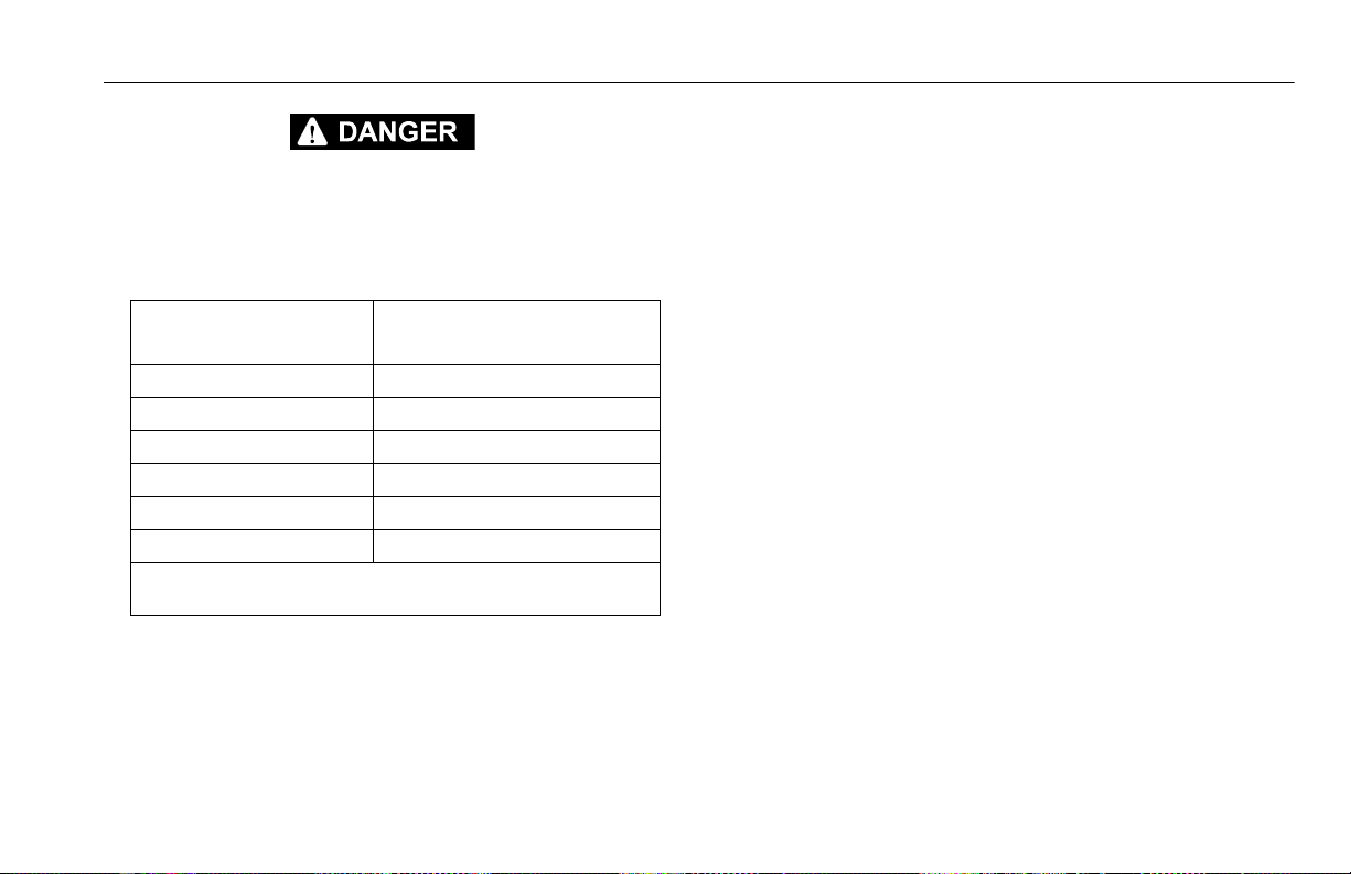
INDICATES AN IMMINENTLY HAZARDOUS SITUATION. IF NOT AVOIDED, WILL
RESULT IN SERIOUS INJURY OR DEATH. THIS DECAL WILL HAVE A RED BACKGROUND.
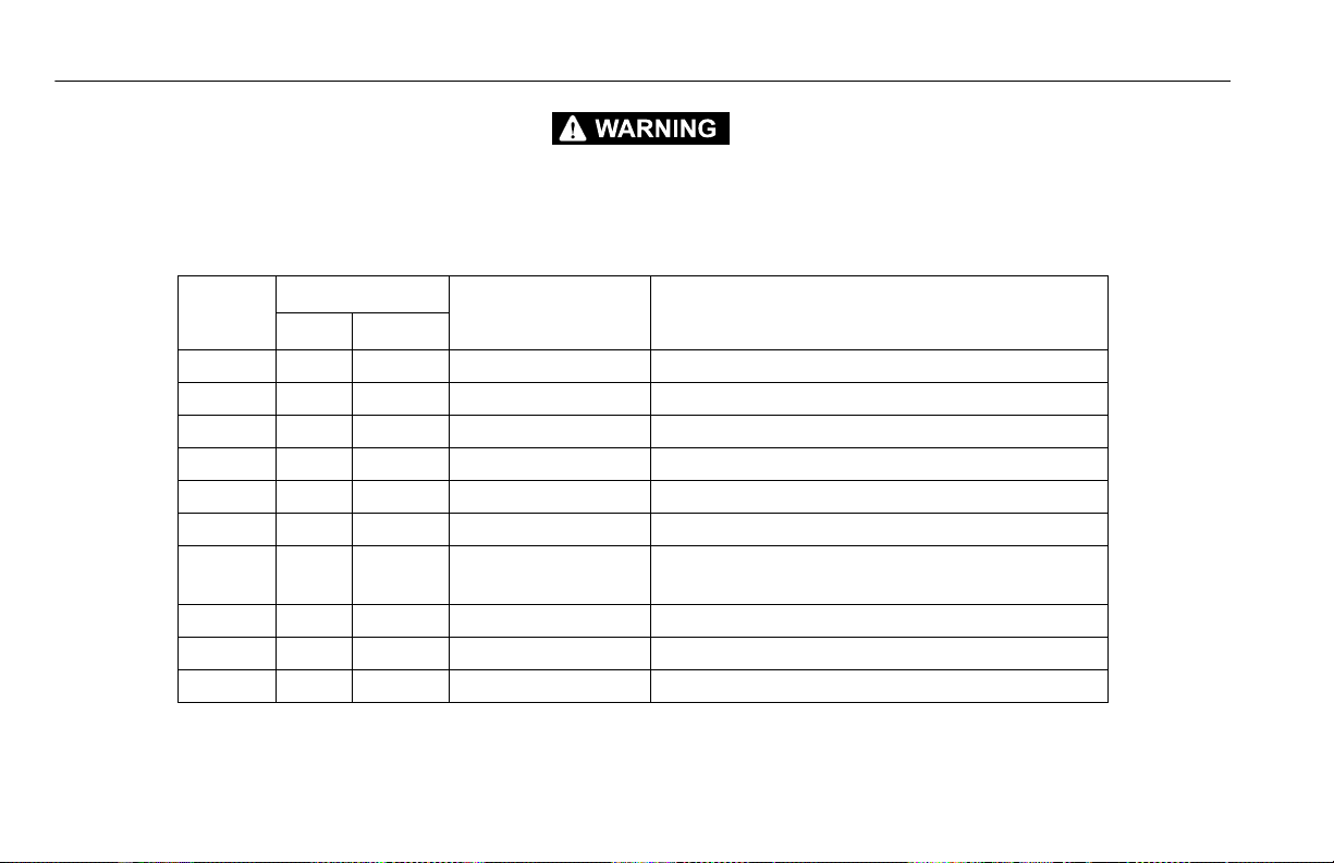
INDICATES A POTENTIALITY HAZARDOUS SITUATION. IF NOT AVOIDED,
COULD
RESULT IN SERIOUS INJURY OR DEATH. THIS DECAL WILL HAVE AN
ORANGE BACKGROUND.
b – JLG Lift – 3121684
INDICATES A POTENTIALITY HAZARDOUS SITUATION. IF NOT AVOIDED, MAY
RESULT IN MINOR OR MODERATE INJURY. IT MAY ALSO ALERT AGAINST
UNSAFE PRACTICES. THIS DECAL WILL HAVE A YELLOW BACKGROUND.
INDICATES INFORMATION OR A COMPANY POLICY THAT RELATES DIRECTLY
OR INDIRECTLY TO THE SAFETY OF PERSONNEL OR PROTECTION OF PROPERTY.
Page 5

SECTION - SAFETY ALERT SYMBOLS AND SAFETY SIGNAL WORDS
NOTICE
NOTICE
THIS PRODUCT MUST COMPLY WITH ALL SAFETY RELATED BULLETINS. CONTACT JLG INDUSTRIES, INC. OR THE LOCAL AUTHORIZED JLG REPRESENTATIVE FOR INFORMATION REGARDING SAFETY RELATED BULLETINS WHICH
MAY HAVE BEEN ISSUED FOR THIS PRODUCT.
JLG INDUSTRIES, INC. SENDS SAFETY RELATED BULLETINS TO THE OWNER OF
RECORD OF THIS MACHINE. CONTACT JLG INDUSTRIES, INC. TO ENSURE THAT
THE CURRENT OWNER RECORDS ARE UPDATED AND ACCURATE.
JLG INDUSTRIES, INC. MUST BE NOTIFIED IMMEDIATELY IN ALL INSTANCES
WHERE JLG PRODUCTS HAVE BEEN INVOLVED IN AN ACCIDENT INVOLVING
BODILY INJURY OR DEATH OF PERSONNEL OR WHEN SUBSTANTIAL DAMAGE
HAS OCCURRED TO PERSONAL PROPERTY OR THE JLG PRODUCT.
For:
• Accident Reporting
• Product Safety Publica-
tions
• Current Owner Updates
• Questions Regarding
Product Safety
• Standards and Regulations
Compliance Information
• Questions Regarding Special
Product Applications
• Questions Regarding Product Modifications
Contact:
Product Safety and Reliability Department
JLG Industries, Inc.
13224 Fountainhead Plaza
Hagerstown, MD 21742
USA
or Your Local JLG Office
(See addresses on manual rear cover)
In USA:
Toll Free: 877-JLG-SAFE (877-554-7233)
Outside USA:
Phone: 240-420-2661
E-mail: ProductSafety@JLG.com
3121684 – JLG Lift – c
Page 6

SECTION - REVISION LOG
Original Issue of Manual. . . . . . . . . . . . . . . . . . . . . September 22, 2014
REVISION LOG
d – JLG Lift – 3121684
Page 7

TABLE OF CONTENTS
SECTION - PARAGRAPH, SUBJECT PAGE SECTION - PARAGRAPH, SUBJECT PAGE
FOREWORD. . . . . . . . . . . . . . . . . . . . . . . . . . . . . . . . . . . . . . . . . . . . . . . A
SAFETY ALERT SYMBOLS AND SAFETY SIGNAL WORDS . . . . . B
Contact: . . . . . . . . . . . . . . . . . . . . . . . . . . . . . . . . . . . . . . . . . . . . . . . . C
In USA: . . . . . . . . . . . . . . . . . . . . . . . . . . . . . . . . . . . . . . . . . . . . . . . . . C
Outside USA:. . . . . . . . . . . . . . . . . . . . . . . . . . . . . . . . . . . . . . . . . . . . C
REVISION LOG . . . . . . . . . . . . . . . . . . . . . . . . . . . . . . . . . . . . . . . . . . . . D
SECTION - 1 - SAFETY PRECAUTIONS
1.1 GENERAL . . . . . . . . . . . . . . . . . . . . . . . . . . . . . . . . . . . . . . . . . . . . . . . .1-1
1.2 PRE-OPERATION . . . . . . . . . . . . . . . . . . . . . . . . . . . . . . . . . . . . . . . . .1-2
Operator Training and Knowledge. . . . . . . . . . . . . . . . . . . . . .1-2
Workplace Inspection . . . . . . . . . . . . . . . . . . . . . . . . . . . . . . . . . .1-2
Machine Inspection . . . . . . . . . . . . . . . . . . . . . . . . . . . . . . . . . . . .1-3
1.3 OPERATION. . . . . . . . . . . . . . . . . . . . . . . . . . . . . . . . . . . . . . . . . . . . . .1-3
General . . . . . . . . . . . . . . . . . . . . . . . . . . . . . . . . . . . . . . . . . . . . . . . .1-3
Trip and Fall Hazards . . . . . . . . . . . . . . . . . . . . . . . . . . . . . . . . . . .1-5
Electrocution Hazards . . . . . . . . . . . . . . . . . . . . . . . . . . . . . . . . . .1-6
Tipping Hazards . . . . . . . . . . . . . . . . . . . . . . . . . . . . . . . . . . . . . . .1-7
Crushing and Collision Hazards. . . . . . . . . . . . . . . . . . . . . . . . .1-9
1.4 TOWING, LIFTING, AND HAULING. . . . . . . . . . . . . . . . . . . . . . . 1-11
1.5 MAINTENANCE . . . . . . . . . . . . . . . . . . . . . . . . . . . . . . . . . . . . . . . . 1-11
Maintenance Hazards . . . . . . . . . . . . . . . . . . . . . . . . . . . . . . . . 1-11
Battery Hazards . . . . . . . . . . . . . . . . . . . . . . . . . . . . . . . . . . . . . . 1-12
SECTION - 2 - USER RESPONSIBILITIES, MACHINE PREPARATION
AND INSPECTION
2.1 PERSONNEL TRAINING . . . . . . . . . . . . . . . . . . . . . . . . . . . . . . . . . . .2-1
Operator Training. . . . . . . . . . . . . . . . . . . . . . . . . . . . . . . . . . . . . .2-1
Training Supervision . . . . . . . . . . . . . . . . . . . . . . . . . . . . . . . . . . .2-2
Operator Responsibility . . . . . . . . . . . . . . . . . . . . . . . . . . . . . . . .2-2
2.2 PREPARATION, INSPECTION, AND MAINTENANCE . . . . . . . . .2-2
2.3 PRE-START INSPECTION . . . . . . . . . . . . . . . . . . . . . . . . . . . . . . . . . .2-4
2.4 DAILY WALK-AROUND INSPECTION . . . . . . . . . . . . . . . . . . . . . .2-6
2.5 FUNCTION CHECK . . . . . . . . . . . . . . . . . . . . . . . . . . . . . . . . . . . . . . .2-8
SECTION - 3 - MACHINE CONTROLS, INDICATORS AND OPERATION
3.1 GENERAL . . . . . . . . . . . . . . . . . . . . . . . . . . . . . . . . . . . . . . . . . . . . . . . .3-1
3.2 DESCRIPTION . . . . . . . . . . . . . . . . . . . . . . . . . . . . . . . . . . . . . . . . . . . .3-1
3.3 OPERATING CHARACTERISTICS AND LIMITATIONS . . . . . . . .3-2
General. . . . . . . . . . . . . . . . . . . . . . . . . . . . . . . . . . . . . . . . . . . . . . . .3-2
Placards . . . . . . . . . . . . . . . . . . . . . . . . . . . . . . . . . . . . . . . . . . . . . . .3-2
3.4 PLATFORM LOADING . . . . . . . . . . . . . . . . . . . . . . . . . . . . . . . . . . . .3-2
3.5 MACHINE CONTROL LOCATIONS . . . . . . . . . . . . . . . . . . . . . . . . .3-3
3.6 BATTERY CHARGING . . . . . . . . . . . . . . . . . . . . . . . . . . . . . . . . . . . . .3-4
Battery Charger Fault (LED Flash) . . . . . . . . . . . . . . . . . . . . . . .3-5
3.7 GROUND CONTROL STATION. . . . . . . . . . . . . . . . . . . . . . . . . . . . .3-6
Ground Emergency Stop Switch . . . . . . . . . . . . . . . . . . . . . . . .3-7
3121684 – JLG Lift – i
Page 8

TABLE OF CONTENTS
SECTION - PARAGRAPH, SUBJECT PAGE SECTION - PARAGRAPH, SUBJECT PAGE
Key Selector Switch . . . . . . . . . . . . . . . . . . . . . . . . . . . . . . . . . . . .3-7
Platform Lift/Lower Switch . . . . . . . . . . . . . . . . . . . . . . . . . . . . .3-7
MDI-Indicator. . . . . . . . . . . . . . . . . . . . . . . . . . . . . . . . . . . . . . . . . .3-7
Overload Indicator. . . . . . . . . . . . . . . . . . . . . . . . . . . . . . . . . . . . .3-8
3.8 SCISSOR ARM - SAFETY PROP . . . . . . . . . . . . . . . . . . . . . . . . . . .3-10
3.9 PLATFORM CONTROL STATION. . . . . . . . . . . . . . . . . . . . . . . . . .3-12
Platform Emergency Stop Switch) . . . . . . . . . . . . . . . . . . . . .3-13
Lift/Drive Select. . . . . . . . . . . . . . . . . . . . . . . . . . . . . . . . . . . . . . .3-13
Forward/Reverse/Lift/Lower Direction Decal. . . . . . . . . . .3-13
Drive/Lift/Steer Joystick Control . . . . . . . . . . . . . . . . . . . . . . .3-14
Steering And Traveling. . . . . . . . . . . . . . . . . . . . . . . . . . . . . . . .3-15
Steering . . . . . . . . . . . . . . . . . . . . . . . . . . . . . . . . . . . . . . . . . . . . . .3-15
Traveling Forward and Reverse. . . . . . . . . . . . . . . . . . . . . . . .3-15
Raising And Lowering Platform. . . . . . . . . . . . . . . . . . . . . . . .3-17
Arm Guards . . . . . . . . . . . . . . . . . . . . . . . . . . . . . . . . . . . . . . . . . .3-17
Overload Indicator. . . . . . . . . . . . . . . . . . . . . . . . . . . . . . . . . . . .3-17
Tilt Indicator Warning Light and Alarm . . . . . . . . . . . . . . . .3-18
Horn . . . . . . . . . . . . . . . . . . . . . . . . . . . . . . . . . . . . . . . . . . . . . . . . .3-18
Low Battery Charge and System Fault Indicator . . . . . . . .3-18
Alarm . . . . . . . . . . . . . . . . . . . . . . . . . . . . . . . . . . . . . . . . . . . . . . . .3-18
3.10 PLATFORM EXTENSION . . . . . . . . . . . . . . . . . . . . . . . . . . . . . . . . .3-19
3.11 PARKING AND STOWING MACHINE. . . . . . . . . . . . . . . . . . . . . .3-20
Anti-Vandalism Package - Option. . . . . . . . . . . . . . . . . . . . . .3-21
3.12 MACHINE LIFTING AND TIE DOWN . . . . . . . . . . . . . . . . . . . . . .3-21
Lifting . . . . . . . . . . . . . . . . . . . . . . . . . . . . . . . . . . . . . . . . . . . . . . . .3-21
Tie Down. . . . . . . . . . . . . . . . . . . . . . . . . . . . . . . . . . . . . . . . . . . . .3-21
3.13 TOWING. . . . . . . . . . . . . . . . . . . . . . . . . . . . . . . . . . . . . . . . . . . . . . . .3-24
Electric Brake Release . . . . . . . . . . . . . . . . . . . . . . . . . . . . . . . . .3-24
Mechanical Brake Release . . . . . . . . . . . . . . . . . . . . . . . . . . . . .3-25
SECTION - 4 - EMERGENCY PROCEDURES
4.1 GENERAL INFORMATION. . . . . . . . . . . . . . . . . . . . . . . . . . . . . . . . . 4-1
4.2 EMERGENCY OPERATION . . . . . . . . . . . . . . . . . . . . . . . . . . . . . . . . 4-1
Operator Unable to Control Machine . . . . . . . . . . . . . . . . . . .4-1
Platform Caught Overhead. . . . . . . . . . . . . . . . . . . . . . . . . . . . . 4-1
Righting of Tipped Machine. . . . . . . . . . . . . . . . . . . . . . . . . . . . 4-1
4.3 PLATFORM MANUAL DESCENT. . . . . . . . . . . . . . . . . . . . . . . . . . . 4-1
4.4 INCIDENT NOTIFICATION . . . . . . . . . . . . . . . . . . . . . . . . . . . . . . . . 4-2
SECTION - 5 - GENERAL SPECIFICATIONS AND MAINTENANCE
5.1 INTRODUCTION . . . . . . . . . . . . . . . . . . . . . . . . . . . . . . . . . . . . . . . . .5-1
Other Publications Available Specific to this Machine:. . . 5-1
5.2 OPERATING SPECIFICATIONS. . . . . . . . . . . . . . . . . . . . . . . . . . . . . 5-2
Platform Capacities . . . . . . . . . . . . . . . . . . . . . . . . . . . . . . . . . . . . 5-3
Machine Dimensional Data . . . . . . . . . . . . . . . . . . . . . . . . . . . .5-4
Tires. . . . . . . . . . . . . . . . . . . . . . . . . . . . . . . . . . . . . . . . . . . . . . . . . . .5-4
Batteries. . . . . . . . . . . . . . . . . . . . . . . . . . . . . . . . . . . . . . . . . . . . . . .5-4
Electrical System. . . . . . . . . . . . . . . . . . . . . . . . . . . . . . . . . . . . . . . 5-5
5.3 CRITICAL STABILITY WEIGHTS . . . . . . . . . . . . . . . . . . . . . . . . . . . . 5-5
ii – JLG Lift – 3121684
Page 9

TABLE OF CONTENTS
SECTION - PARAGRAPH, SUBJECT PAGE SECTION - PARAGRAPH, SUBJECT PAGE
5.4 LUBRICATION . . . . . . . . . . . . . . . . . . . . . . . . . . . . . . . . . . . . . . . . . . . .5-6
Lubrication Capacities. . . . . . . . . . . . . . . . . . . . . . . . . . . . . . . . . .5-6
Hydraulic Oil . . . . . . . . . . . . . . . . . . . . . . . . . . . . . . . . . . . . . . . . . . .5-6
Lubrication Specifications . . . . . . . . . . . . . . . . . . . . . . . . . . . . . .5-6
5.5 MAINTENANCE . . . . . . . . . . . . . . . . . . . . . . . . . . . . . . . . . . . . . . . . . .5-8
Hydraulic Oil Check Procedure . . . . . . . . . . . . . . . . . . . . . . . . .5-8
5.6 BATTERY MAINTENANCE . . . . . . . . . . . . . . . . . . . . . . . . . . . . . . . . .5-9
Battery Maintenance and Safety Practices. . . . . . . . . . . . . . .5-9
Battery Quick-Disconnect - (If Equipped) . . . . . . . . . . . . . . . .5-9
5.7 TIRES AND WHEELS . . . . . . . . . . . . . . . . . . . . . . . . . . . . . . . . . . . . 5-10
Tire Wear and Damage . . . . . . . . . . . . . . . . . . . . . . . . . . . . . . . 5-10
Wheel and Tire Replacement . . . . . . . . . . . . . . . . . . . . . . . . . 5-10
Wheel Installation. . . . . . . . . . . . . . . . . . . . . . . . . . . . . . . . . . . . 5-11
5.8 DECAL INSTALLATION. . . . . . . . . . . . . . . . . . . . . . . . . . . . . . . . . . 5-12
5.9 DIAGNOSTIC TROUBLE CODES (DTC). . . . . . . . . . . . . . . . . . . . 5-14
5.10 DTC CHECK TABLE INDEX . . . . . . . . . . . . . . . . . . . . . . . . . . . . . . 5-14
5.11 DIAGNOSTIC TROUBLE CODES (DTC) CHECK TABLES . . . . 5-15
0-0 Help Comments. . . . . . . . . . . . . . . . . . . . . . . . . . . . . . . . . . 5-15
2-1 Power-Up . . . . . . . . . . . . . . . . . . . . . . . . . . . . . . . . . . . . . . . . 5-16
2-2 Platform Controls . . . . . . . . . . . . . . . . . . . . . . . . . . . . . . . . 5-17
2-3 Ground Controls . . . . . . . . . . . . . . . . . . . . . . . . . . . . . . . . . 5-18
2-4 Low/High Temperature Cutout . . . . . . . . . . . . . . . . . . . 5-19
2-5 Function Prevented . . . . . . . . . . . . . . . . . . . . . . . . . . . . . . 5-19
3-1 Line Contactor Open Circuit . . . . . . . . . . . . . . . . . . . . . . 5-21
3-2 Line Contactor Short Circuit . . . . . . . . . . . . . . . . . . . . . . 5-21
3-3 Ground Output Driver . . . . . . . . . . . . . . . . . . . . . . . . . . . . 5-22
4-2 Thermal Limit (SOA) . . . . . . . . . . . . . . . . . . . . . . . . . . . . . . 5-23
4-4 Battery Supply . . . . . . . . . . . . . . . . . . . . . . . . . . . . . . . . . . . 5-24
6-6 Communication. . . . . . . . . . . . . . . . . . . . . . . . . . . . . . . . . . 5-24
7-7 Electric Motor . . . . . . . . . . . . . . . . . . . . . . . . . . . . . . . . . . . . 5-25
8-2 LSS - Load Sensing System. . . . . . . . . . . . . . . . . . . . . . . . 5-27
8-4 Elevation Switch . . . . . . . . . . . . . . . . . . . . . . . . . . . . . . . . . 5-27
9-9 Hardware . . . . . . . . . . . . . . . . . . . . . . . . . . . . . . . . . . . . . . . . 5-28
SECTION - 6 - INSPECTION AND REPAIR LOG
3121684 – JLG Lift – iii
Page 10

TABLE OF CONTENTS
SECTION - PARAGRAPH, SUBJECT PAGE SECTION - PARAGRAPH, SUBJECT PAGE
LIST OF FIGURES
2-1. Daily Walk-Around Inspection . . . . . . . . . . . . . . . . . . . . . . . . 2-7
2-2. Machine Limit Switch Location . . . . . . . . . . . . . . . . . . . . . . . 2-9
3-1. R6 - Location of Machine Controls. . . . . . . . . . . . . . . . . . . . . 3-3
3-2. Charger Decal LED Indicators . . . . . . . . . . . . . . . . . . . . . . . . . 3-4
3-3. Ground Control Station. . . . . . . . . . . . . . . . . . . . . . . . . . . . . . .3-6
3-4. MDI Indicator . . . . . . . . . . . . . . . . . . . . . . . . . . . . . . . . . . . . . . . .3-8
3-5. Location of Manual Descent Control . . . . . . . . . . . . . . . . . .3-9
3-6. R6 - Scissor Arm - Safety Prop . . . . . . . . . . . . . . . . . . . . . . . .3-10
3-7. Platform Control Station. . . . . . . . . . . . . . . . . . . . . . . . . . . . .3-12
3-8. Platform Control Components. . . . . . . . . . . . . . . . . . . . . . .3-14
3-9. Grade and Sideslope Definition . . . . . . . . . . . . . . . . . . . . . .3-16
3-10. Platform Deck Extension . . . . . . . . . . . . . . . . . . . . . . . . . . . .3-19
3-11. Securing Control Station to Platform. . . . . . . . . . . . . . . . .3-20
3-12. Fork Lift Pockets - Location . . . . . . . . . . . . . . . . . . . . . . . . . .3-21
3-13. Lifting Using Spreader Bar and Lift Lug Locations. . . . .3-22
3-14. Tie Down and Lift Lug Locations . . . . . . . . . . . . . . . . . . . . .3-23
3-15. Electric Brake Release - Location . . . . . . . . . . . . . . . . . . . . .3-24
3-16. Brake - Manual Disengage. . . . . . . . . . . . . . . . . . . . . . . . . . .3-25
4-1. Location of Manual Descent Control . . . . . . . . . . . . . . . . . .4-2
5-1. Hydraulic Oil Check Procedure. . . . . . . . . . . . . . . . . . . . . . . . 5-8
5-2. Battery Fluid Level. . . . . . . . . . . . . . . . . . . . . . . . . . . . . . . . . . . .5-9
5-3. Wheel Lug Nut Tightening Sequence . . . . . . . . . . . . . . . .5-11
5-4. Machine Decal Installation. . . . . . . . . . . . . . . . . . . . . . . . . . .5-12
LIST OF TABLES
1-1 Minimum Approach Distances (M.A.D.) . . . . . . . . . . . . . . .1-7
1-2 Beaufort Scale (For Reference Only) . . . . . . . . . . . . . . . . . . .1-8
2-1 Inspection and Maintenance Table. . . . . . . . . . . . . . . . . . . .2-3
2-2 High Drive Cutout Height. . . . . . . . . . . . . . . . . . . . . . . . . . . . .2-8
2-3 Tilt Activation Setting - Australia . . . . . . . . . . . . . . . . . . . . . .2-9
3-1 Battery Charger Fault (LED Flash) . . . . . . . . . . . . . . . . . . . . .3-5
5-1 Operating Specifications . . . . . . . . . . . . . . . . . . . . . . . . . . . . .5-2
5-2 Platform Capacities. . . . . . . . . . . . . . . . . . . . . . . . . . . . . . . . . . .5-3
5-3 Dimensions . . . . . . . . . . . . . . . . . . . . . . . . . . . . . . . . . . . . . . . . . .5-4
5-4 Tire Specifications . . . . . . . . . . . . . . . . . . . . . . . . . . . . . . . . . . . .5-4
5-5 Battery Specifications . . . . . . . . . . . . . . . . . . . . . . . . . . . . . . . .5-4
5-6 Electrical System Specifications . . . . . . . . . . . . . . . . . . . . . . .5-5
5-7 Critical Stability Weights. . . . . . . . . . . . . . . . . . . . . . . . . . . . . .5-5
5-8 Capacities. . . . . . . . . . . . . . . . . . . . . . . . . . . . . . . . . . . . . . . . . . . .5-6
5-9 Hydraulic Oil . . . . . . . . . . . . . . . . . . . . . . . . . . . . . . . . . . . . . . . . .5-6
5-10 Lubrication Specifications . . . . . . . . . . . . . . . . . . . . . . . . . . . . 5-6
5-11 Hydraulic Oil Specifications. . . . . . . . . . . . . . . . . . . . . . . . . . .5-7
5-12 Wheel Torque Chart . . . . . . . . . . . . . . . . . . . . . . . . . . . . . . . . .5-11
5-13 Machine Decal Installation Chart. . . . . . . . . . . . . . . . . . . . .5-13
6-1 Inspection and Repair Log . . . . . . . . . . . . . . . . . . . . . . . . . . . .6-1
iv – JLG Lift – 3121684
Page 11

SECTION 1. SAFETY PRECAUTIONS
SECTION 1 - SAFETY PRECAUTIONS
1.1 GENERAL
This section outlines the necessary precautions for proper
and safe machine usage and maintenance. In order to promote proper machine usage, it is mandatory that a daily
routine is established based on the content of this manual.
A maintenance program, using the information provided
in this manual and the Service and Maintenance Manual,
must also be established by a qualified person and must
be followed to ensure that the machine is safe to operate.
The owner/user/operator/lessor/lessee of the machine
must not accept operating responsibility until this manual
has been read, training is accomplished, and operation of
the machine has been completed under the supervision of
an experienced and qualified operator.
These sections contain the responsibilities of the owner,
user, operator, lessor, and lessee concerning safety, training, inspection, maintenance, application, and operation.If
there are any questions with regard to safety, training,
inspection, maintenance, application, and operation,
please contact JLG Industries, Inc. (“JLG”).
FAILURE TO COMPLY WITH THE SAFETY PRECAUTIONS LISTED IN THIS MANUAL COULD RESULT IN MACHINE DAMAGE, PROPERTY DAMAGE, PERSONAL
INJURY OR DEATH.
3121684 – JLG Lift – 1-1
Page 12

SECTION 1 - SAFETY PRECAUTIONS
1.2 PRE-OPERATION
Operator Training and Knowledge
• The Operation and Safety Manual must be read and understood in its entirety before operating the machine. For clarification, questions, or additional information regarding any
portions of this manual, contact JLG Industries, Inc.
• An operator must not accept operating responsibilities
until adequate training has been given by competent and
authorized persons.
• Allow only those authorized and qualified personnel to
operate the machine who have demonstrated that they
understand the safe and proper operation and maintenance of the unit.
• Read, understand, and obey all DANGERS, WARNINGS, CAUTIONS, and operating instructions on the machine and in
this manual.
• Ensure that the machine is to be used in a manner which is
within the scope of its intended application as determined
by JLG.
• All operating personnel must be familiar with the emergency controls and emergency operation of the machine as
specified in this manual.
• Read, understand, and obey all applicable employer, local,
and governmental regulations as they pertain to your utilization and application of the machine.
Workplace Inspection
• Precautions to avoid all hazards in the work area must be
taken by the user before and during operation of the
machine.
• Do not operate or raise the platform from a position on
trucks, trailers, railway cars, floating vessels, scaffolds or
other equipment unless the application is approved in writing by JLG.
• Before operation, check work area for overhead hazards
such as electric lines, bridge cranes, and other potential
overhead obstructions.
• Check floor surfaces for holes, bumps, drop-offs, obstructions, debris, concealed holes, and other potential hazards.
1-2 – JLG Lift – 3121684
Page 13

SECTION 1 - SAFETY PRECAUTIONS
• Check the work area for hazardous locations. Do not operate the machine in hazardous environments unless
approved for that purpose by JLG.
• Ensure that the ground conditions are adequate to support
the maximum tire load indicated on the tire load decals
located on the chassis adjacent to each wheel.
• This machine can be operated in nominal ambient temperatures of 0
mize operation outside of this temperature range.
o
F to 104o F (-20o C to 40o C). Consult JLG to opti-
Machine Inspection
• Do not operate this machine until the inspections and functional checks have been performed as specified in Section 2
of this manual.
• Do not operate this machine until it has been serviced and
maintained according to the maintenance and inspection
requirements as specified in the machine’s Service and
Maintenance Manual.
• Ensure all safety devices are operating properly. Modification of these devices is a safety violation.
MODIFICATION OR ALTERATION OF AN AERIAL WORK PLATFORM SHALL BE
MADE ONLY WITH PRIOR WRITTEN PERMISSION FROM THE MANUFACTURER.
• Do not operate any machine on which the safety or instruction placards or decals are missing or illegible.
• Check the machine for modifications to original components. Ensure that any modifications have been approved
by JLG.
• Avoid accumulation of debris on platform deck. Keep mud,
oil, grease, and other slippery substances from footwear
and platform deck.
1.3 OPERATION
General
• Machine operation requires your full attention. Bring the
machine to a full stop before using any device, i.e. cell
phones, two-way radios, etc. that will distract your attention
from safely operating the machine.
• Do not use the machine for any purpose other than positioning personnel, their tools, and equipment.
• Before operation, the user must be familiar with the
machine capabilities and operating characteristics of all
functions.
• Never operate a malfunctioning machine. If a malfunction
occurs, shut down the machine. Remove the unit from service and notify the proper authorities.
3121684 – JLG Lift – 1-3
Page 14

SECTION 1 - SAFETY PRECAUTIONS
• Do not remove, modify, or disable any safety devices.
• Never slam a control switch or lever through neutral to an
opposite direction. Always return switch to neutral and stop
before moving the switch to the next function. Operate
controls with slow and even pressure.
• Do not allow personnel to tamper with or operate the
machine from the ground with personnel in the platform,
except in an emergency.
• Do not carry materials directly on platform railing unless
approved by JLG.
• When two or more persons are in the platform, the operator
shall be responsible for all machine operations.
• Always ensure that power tools are properly stowed and
never left hanging by their cord from the platform work
area.
• Do not assist a stuck or disabled machine by pushing or
pulling except by pulling at the chassis tie-down lugs.
• Fully lower platform and shut off all power before leaving
machine.
• Remove all rings, watches, and jewelry when operating
machine. Do not wear loose fitting clothing or long hair
unrestrained which may become caught or entangled in
equipment.
• Persons under the influence of drugs or alcohol or who are
subject to seizures, dizziness or loss of physical control must
not operate this machine.
• The following information is provided in accordance with
the requirements of the European Machinery Directive
2006/42/EC and is only applicable to CE machines.
For electric powered machines, the equivalent continuous
A-Weighted sound pressure level at the work platform is
less than 70dB(A).
For combustion engine powered machines, guaranteed
Sound Power Level (LWA) per European Directive 2000/ 14/
EC (Noise Emission in the Environment by Equipment for
Use Outdoors) based on test methods in accordance with
Annex III, Part B, Method 1 and 0 of the directive, is 109 dB.
The vibration total value to which the hand-arm system is
subjected does not exceed 2,5 m/s2. The highest root mean
square value of weighted acceleration to which the whole
body is subjected does not exceed 0,5 m/s2.
1-4 – JLG Lift – 3121684
Page 15
SECTION 1 - SAFETY PRECAUTIONS
Trip and Fall Hazards
• Prior to operation, ensure all gates and rails are fastened
and secured in their proper position.
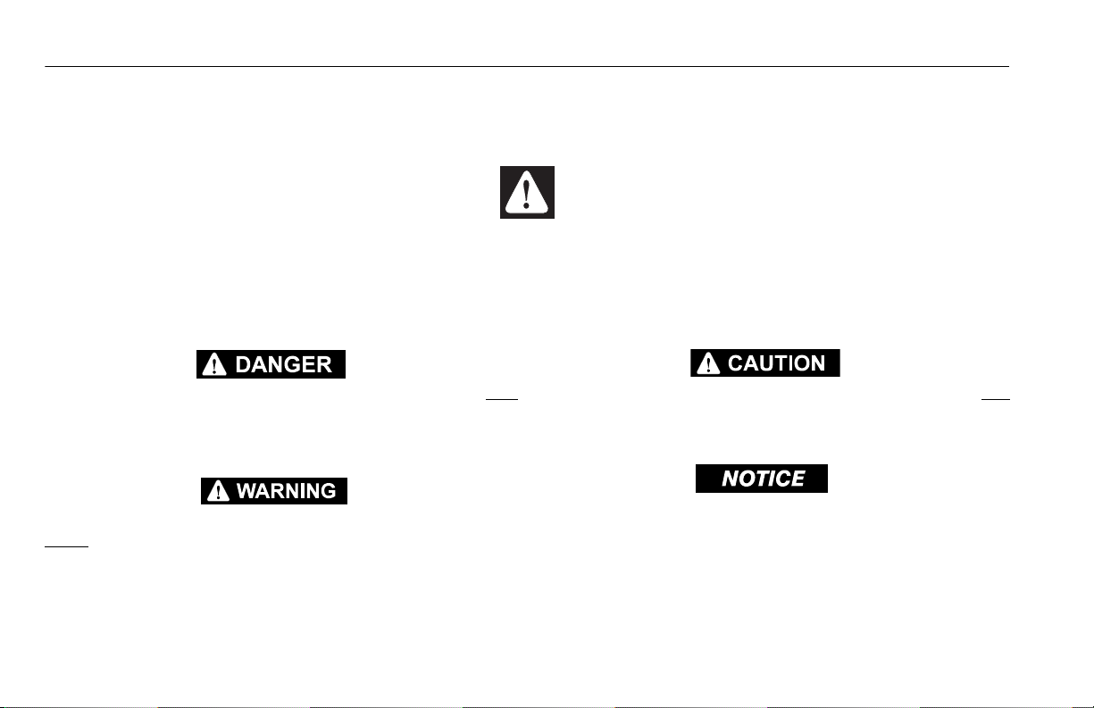
• JLG Industries, Inc. recommends that all persons in the platform wear a full body harness with a lanyard attached to an
authorized lanyard anchorage point while operating this
machine. For further information regarding fall protection
requirements on JLG products, contact JLG Industries, Inc.
• Identify the designated lanyard anchorage point(s) at the
platform and securely attach the lanyard. Attach only one
(1) lanyard per lanyard anchorage point.
• Enter and exit only through gate area. Use extreme caution
when entering or leaving platform. Ensure that the platform
assembly is fully lowered. Face the machine when entering
or leaving the platform. Always maintain “three point contact” with the machine, using two hands and one foot or
two feet and one hand at all times during entry and exit.
.
• Keep both feet firmly positioned on the platform floor at all
times. Never position ladders, boxes, steps, planks, or similar items on unit to provide additional reach for any purpose.
• Never use the scissor arm assembly to gain access to or
leave the platform.
• Keep oil, mud, and slippery substances cleaned from footwear and the platform floor.
3121684 – JLG Lift – 1-5
Page 16
SECTION 1 - SAFETY PRECAUTIONS
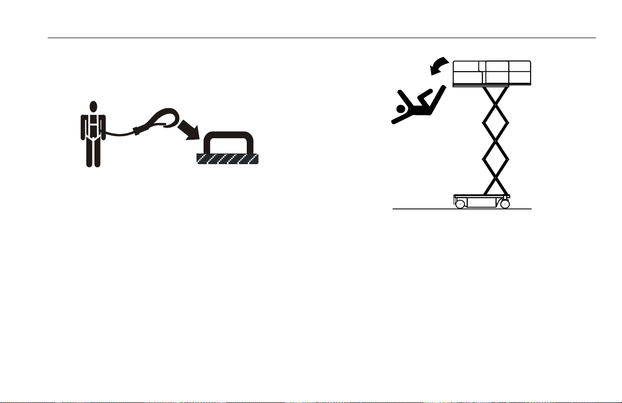
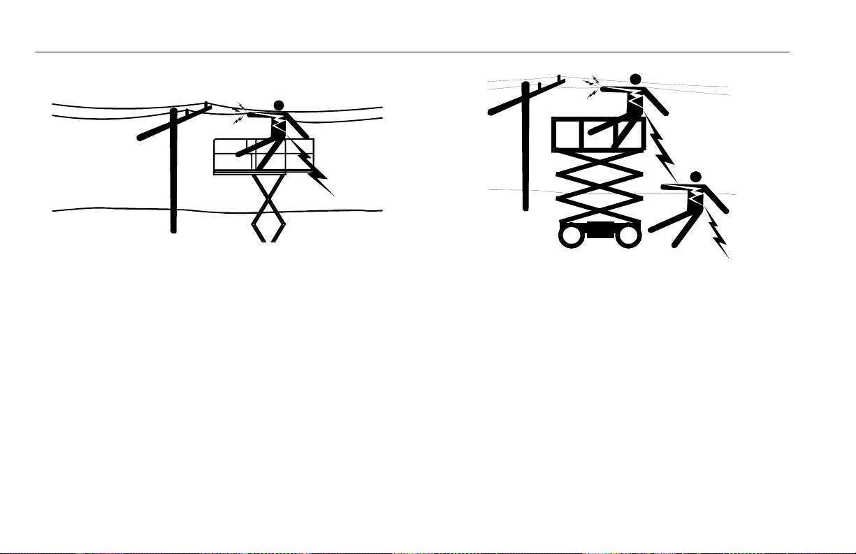
Electrocution Hazards
• This machine is not insulated and does not provide protection from contact or proximity to electrical current.
• Maintain distance from electrical lines, apparatus, or any
energized (exposed or insulated) parts according to the
Minimum Approach Distance (MAD) as shown in Table 1-1.
• Allow for machine movement and electrical line swaying.
• Maintain a clearance of at least 10 ft. (3m) between any part
of the machine and its occupants, their tools, and their
equipment from any electrical line or apparatus carrying up
to 50,000 volts. One foot additional clearance is required for
every additional 30,000 volts or less.
1-6 – JLG Lift – 3121684
• The minimum approach distance may be reduced if insulat-
ing barriers are installed to prevent contact, and the barriers are rated for the voltage of the line being guarded.
These barriers shall not be part of (or attached to) the
machine. The minimum approach distance shall be reduced
to a distance within the designed working dimensions of
the insulating barrier. This determination shall be made by
a qualified person in accordance with the employer, local,
or governmental requirements for work practices near
energized equipment.
Page 17
DO NOT MANEUVER MACHINE OR PERSONNEL INSIDE PROHIBITED ZONE (MAD).
ASSUME ALL ELECTRICAL PARTS AND WIRING ARE ENERGIZED UNLESS KNOWN OTHERWISE.
Table 1-1. Minimum Approach Distances (M.A.D.)
VOLTAGE RANGE
(Phase to Phase)
MINIMUM APPROACH DISTANCE
in Feet (Meters)
0 to 50 KV 10 (3)
Over 50KV to 200 KV 15 (5)
Over 200 KV to 350 KV 20 (6)
Over 350 KV to 500 KV 25 (8)
Over 500 KV to 750 KV 35 (11)
Over 750 KV to 1000 KV 45 (14)
NOTE: This requirement shall apply except where employer, local or govern-
mental regulations are more stringent.
SECTION 1 - SAFETY PRECAUTIONS
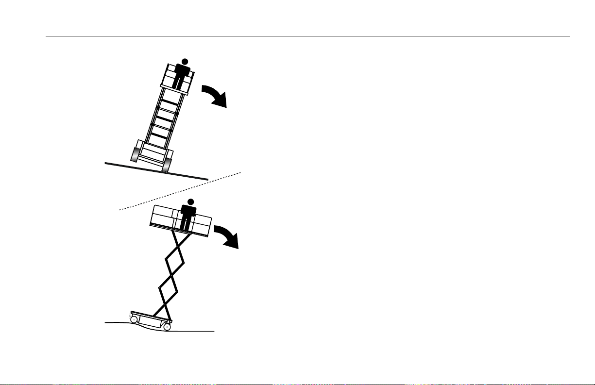
Tipping Hazards
• Ensure that the ground conditions are adequate to support
the maximum tire load indicated on the tire load decals
located on the chassis adjacent to each wheel. Do not travel
on unsupported surfaces.
• The user must be familiar with the driving surface before
driving. Do not exceed the allowable sideslope and grade
while driving.
• Do not elevate platform or drive with platform elevated
while on or near a sloping, uneven, or soft surface. Ensure
machine is positioned on a firm, level and smooth surface
before elevating platform or driving with the platform in
the elevated position.
• Before driving on floors, bridges, trucks, and other surfaces,
check allowable capacity of the surfaces.
• Never exceed the maximum work load as specified on the
platform. Keep all loads within the confines of the platform,
unless authorized by JLG.
• Keep the chassis of the machine a minimum of 2 ft. (0.6m)
from holes, bumps, drop-offs, obstructions, debris, concealed holes, and other potential hazards at the ground
level.
• Do not operate the machine when wind conditions exceed
specifications shown in Section 5, Table 5-2 or as shown on
the capacity placard on the platform billboard.
3121684 – JLG Lift – 1-7
Page 18
SECTION 1 - SAFETY PRECAUTIONS
DO NOT OPERATE THE MACHINE WHEN WIND CONDITIONS EXCEED SPECIFICATIONS SHOWN IN SECTION 5, TABLE 5-2 OR AS SHOWN ON THE CAPACITY PLACARD ON THE PLATFORM BILLBOARD.
Table 1-2. Beaufort Scale (For Reference Only)
BEAUFORT
NUMBER
WIND SPEED
DESCRIPTION LAND CONDITIONS
mph m/s
0 0 0-0.2 Calm Calm. Smoke rises vertically.
1 1-3 0.3-1.5 Light air Wind motion visible in smoke.
2 4-7 1.6-3.3 Light breeze Wind felt on exposed skin. Leaves rustle.
3 8-12 3.4-5.4 Gentle breeze Leaves and smaller twigs in constant motion.
4 13-18 5.5-7.9 Moderate breeze Dust and loose paper raised. Small branches begin to move.
5 19-24 8.0-10.7 Fresh breeze Smaller trees sway.
6 25-31 10.8-13.8 Strong breeze Large branches in motion. Flags waving near horizontal. Umbrella
use becomes difficult.
7 32-38 13.9-17.1 Near Gale/Moderate Gale Whole trees in motion. Effort needed to walk against the wind.
8 39-46 17.2-20.7 Fresh Gale Twigs broken from trees. Cars veer on road.
9 47-54 20.8-24.4 Strong Gale Light structure damage.
1-8 – JLG Lift – 3121684
Page 19
SECTION 1 - SAFETY PRECAUTIONS
• Never attempt to use the machine as a crane. Do not tie-off
machine to any adjacent structure. Never attach wire, cable,
or any similar items to platform.
• Do not cover the platform sides or carry large surface-area
items in the platform when operating outdoors. The addition of such items increases the exposed wind area of the
machine.
• Do not increase the platform size with unauthorized deck
extensions or attachments.
• If the scissor arm assembly or platform is caught so that one
or more wheels are off the ground, all persons must be
removed before attempting to free the machine. Use
cranes, forklift trucks, or other appropriate equipment to
stabilize machine and remove personnel.
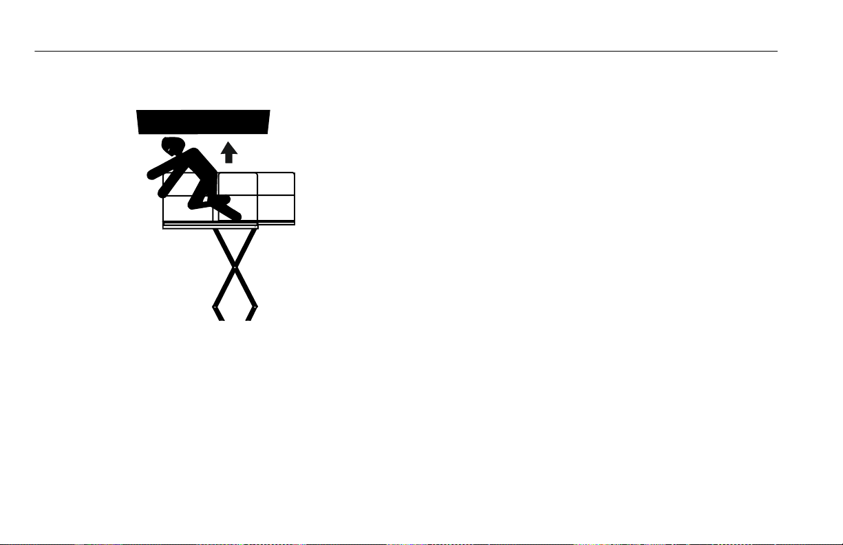
Crushing and Collision Hazards
• Approved head gear must be worn by all operating and
ground personnel.
• Keep hands and limbs out of the scissor arm assembly during operation and when elevated without safety prop
engaged.
• Watch for obstructions around machine and overhead
when driving. Check clearances above, on sides, and bottom of platform when lifting or lowering platform.
3121684 – JLG Lift – 1-9
Page 20
SECTION 1 - SAFETY PRECAUTIONS
• During operation, keep all body parts inside platform railing.
• Always post a lookout when driving in areas where vision is
obstructed.
• Keep non-operating personnel at least 6 ft. (1.8m) away
from machine during all operations.
• Under all travel conditions, the operator must limit travel
speed according to conditions of ground surface, congestion, visibility, slope, location of personnel, and other factors.
• Be aware of stopping distances in all drive speeds. When
driving in high speed, switch to low speed before stopping.
Travel grades in low speed only.
• Do not use high speed drive in restricted or close quarters
or when driving in reverse.
• Exercise extreme caution at all times to prevent obstacles
from striking or interfering with operating controls and persons in the platform.
• Ensure that operators of other overhead and floor level
machines are aware of the aerial work platform’s presence.
Disconnect power to overhead cranes. Barricade floor area
if necessary.
• Do not operate over ground personnel. Warn personnel not
to work, stand, or walk under a raised platform. Position
barricades on floor as necessary.
1-10 – JLG Lift – 3121684
Page 21

SECTION 1 - SAFETY PRECAUTIONS
1.4 TOWING, LIFTING, AND HAULING
• Never allow personnel in platform while towing, lifting, or
hauling.
• This machine should not be towed, except in the event of
emergency, malfunction, power failure, or loading/unloading. Refer to emergency towing procedures.
• Ensure platform is fully retracted and completely empty of
tools prior to towing, lifting or hauling.
• When lifting machine with a forklift, position forks only at
designated areas of the machine. Lift with a forklift of adequate capacity.
• Refer to Section 3 for lifting information.
1.5 MAINTENANCE
This sub-section contains general safety precautions which
must be observed during maintenance of this machine. Additional precautions to be observed during machine maintenance are inserted at the appropriate points in this manual
and in the Service and Maintenance Manual. It is of utmost
importance that maintenance personnel pay strict attention
to these precautions to avoid possible injury to personnel or
damage to the machine or property. A maintenance program
must be established by a qualified person and must be followed to ensure that the machine is safe.
Maintenance Hazards
• Shut off power to all controls and ensure that all moving
parts are secured from inadvertent motion prior to performing any adjustments or repairs.
• Never work under an elevated platform until it has been
fully lowered to the full down position, if possible, or otherwise supported and restrained from movement with appropriate safety props, blocking, or overhead supports.
• DO NOT attempt to repair or tighten any hydraulic hoses or
fittings while the machine is powered on or when the
hydraulic system is under pressure.
• Always relieve hydraulic pressure
from all hydraulic circuits before
loosening or removing hydraulic
components.
• DO NOT use your hand to check for
leaks. Use a piece of cardboard or
paper to search for leaks. Wear
gloves to help protect hands from
spraying fluid.
• Ensure replacement parts or components are identical or
equivalent to original parts or components.
3121684 – JLG Lift – 1-11
Page 22

SECTION 1 - SAFETY PRECAUTIONS
• Never attempt to move heavy parts without the aid of a
mechanical device. Do not allow heavy objects to rest in an
unstable position. Ensure adequate support is provided
when raising components of the machine.
• Use only approved non-flammable cleaning solvents.
• Do not replace items critical to stability, such as batteries or
solid tires, with items of different weight or specification.
Do not modify unit in any way to affect stability.
• Reference the Service and Maintenance Manual for the
weights of critical stability items.
MODIFICATION OR ALTERATION OF AN AERIAL WORK PLATFORM SHALL BE
MADE ONLY WITH PRIOR WRITTEN PERMISSION FROM THE MANUFACTURER.
Battery Hazards
• Always disconnect batteries when servicing electrical components or when performing welding on the machine.
• Do not allow smoking, open flame, or sparks near battery
during charging or servicing.
• Do not contact tools or other metal objects across the battery terminals.
• Always wear hand, eye, and face protection when servicing
batteries. Ensure that battery acid does not come in contact
with skin or clothing.
BATTERY FLUID IS HIGHLY CORROSIVE. AVOID CONTACT WITH SKIN AND
CLOTHING AT ALL TIMES. IMMEDIATELY RINSE ANY CONTACTED AREA WITH
CLEAN WATER AND SEEK MEDICAL ATTENTION.
• Charge batteries only in a well ventilated area.
• Avoid overfilling the battery fluid level. Add distilled water
to batteries only after the batteries are fully charged.
1-12 – JLG Lift – 3121684
Page 23

SECTION 2 - USER RESPONSIBILITIES, MACHINE PREPARATION AND INSPECTION
SECTION 2. USER RESPONSIBILITIES, MACHINE PREPARATION AND INSPECTION
2.1 PERSONNEL TRAINING
The aerial platform is a personnel handling device; so it is necessary that it be operated and maintained only by trained personnel.
Operator Training
Operator training must cover:
• Use and limitations of the controls in the platform and at the
ground, emergency controls and safety features.
• Control labels, instructions, and warnings on the machine.
• Rules of the employer and government regulations.
• Use of approved fall protection equipment.
• Enough knowledge of the mechanical operation of the machine to
recognize a malfunction or potential malfunction.
• The safest means to operate the machine where overhead obstructions, other moving equipment, and obstacles, depressions, holes,
and drop-offs exist.
• Means to avoid the hazards of unprotected electrical conductors.
• Specific job requirements or machine application.
• Reading and understanding the Operation and Safety Manual.
3121684 – JLG Lift – 2-1
Page 24

SECTION 2 - USER RESPONSIBILITIES, MACHINE PREPARATION AND INSPECTION
Training Supervision
Training must be done under the supervision of a qualified person in an open area free of obstructions until the trainee has
developed the ability to safely control and operate the machine.
Operator Responsibility
The operator must be instructed that he/she has the responsibility and authority to shut down the machine in case of a malfunction or other unsafe condition of either the machine or the
job site.
NOTE: The Manufacturer or Distributor will provide qualified
people for training assistance with the first unit(s) delivered and from that time forward as requested by the user
or his/her personnel.
2.2 PREPARATION, INSPECTION, AND MAINTENANCE
Table 2-1 explains the periodic machine inspections and maintenance recommended by JLG Industries, Inc. Consult local regulations for further requirements for aerial work platforms. The
frequency of inspections and maintenance must be increased
as necessary when the machine is used in a harsh or hostile
environment, if the machine is used with increased frequency,
or if the machine is used in a severe manner.
2-2 – JLG Lift – 3121684
Page 25

SECTION 2 - USER RESPONSIBILITIES, MACHINE PREPARATION AND INSPECTION
NOTICE
Table 2-1. Inspection and Maintenance Table
TYPE FREQUENCY
Pre-Start Inspec tion Before using each day; or
whenever there’s an Operator change.
Pre-Delivery Inspection
(see note below)
Frequent Inspection In service for 3 months or 150 hours, whichever comes
Annual Machine
Inspection
(see note below)
Preventative Maintenance At intervals as specified in the Ser vice and Mainte-
NOTE: Inspection forms are available from JLG. Use the Service and Maintenance Manual to perform inspections.
JLG INDUSTRIES, INC. RECOGNIZES A FACTORY-TRAINED SERVICE TECHNICIAN AS A PERSON WHO HAS SUCCESSFULLY COMPLETED THE JLG SERVICE TRAINING SCHOOL FOR
THE SPECIFIC JLG PRODUCT MODEL.
Before each sale, lease, or rental delivery. Owner, Dealer, or User Qualified JLG
first; or Out of service for a period of more than 3
months; or Purchased used.
Annually, no later than 13 months from the date of
prior inspection.
nance Manual.
PRIMARY
RESPONSIBILITY
User or Operator User or Operator Operation and Safety Manual
Owner, Dealer, or User Qualified JLG
Owner, Dealer, or User Factory Trained Ser-
Owner, Dealer, or User Qualified JLG
SERVICE
QUALIFICATION
Mechanic
Mechanic
vice Technician
(Recommended)
Mechanic
REFERENCE
Service and Maintenance Manual and
applicable JLG inspection form
Service and Maintenance Manual and
applicable JLG inspection form
Service and Maintenance Manual and
applicable JLG inspection form
Service and Maintenance Manual
3121684 – JLG Lift – 2-3
Page 26
SECTION 2 - USER RESPONSIBILITIES, MACHINE PREPARATION AND INSPECTION
2.3 PRE-START INSPECTION
The Pre-Start Inspection should include each of the following:
1. Cleanliness – Check all surfaces for leakage (oil or battery fluid) or foreign objects. Report this to the proper
maintenance personnel.
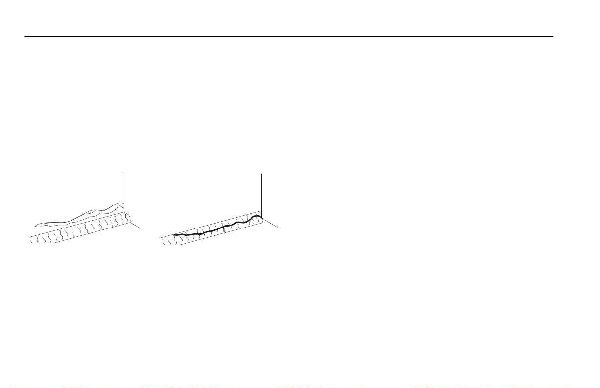
2. Structure - Inspect the machine structure for dents,
damage, weld or parent metal cracks or other discrepancies. Report this to the proper maintenance personnel.
.
Parent Metal Crack Weld Crack
3. Decals and Placards – Check all for cleanliness and
legibility. Ensure none of the decals and placards are
missing. Ensure all illegible decals and placards are
cleaned or replaced. (See Section 5.8, DECAL INSTALLATION)
4. Operation and Safety Manuals - Ensure that a copy
of the Operation and Safety Manual is enclosed in the
weather resistant storage container.
5. “Walk-Around” Inspection – Refer to Figure 2-1. on
page 2-7.
6. Battery – Charge as required.
7. Hydraulic Oil Level - Check the hydraulic oil level in
the pump reservoir, add as required. (See Section 5.5)
8. Accessories/Attachments - Reference the Operation
and Safety Manual of each attachment or accessory
installed upon the machine for specific inspection,
operation, and maintenance instructions.
9. Function Check – Once the “Walk-Around” Inspection
is complete, perform a functional check of all systems
in an area free of overhead and ground level obstructions. Refer to Section 3 for more specific instructions
on the operation of each function.
2-4 – JLG Lift – 3121684
Page 27
SECTION 2 - USER RESPONSIBILITIES, MACHINE PREPARATION AND INSPECTION
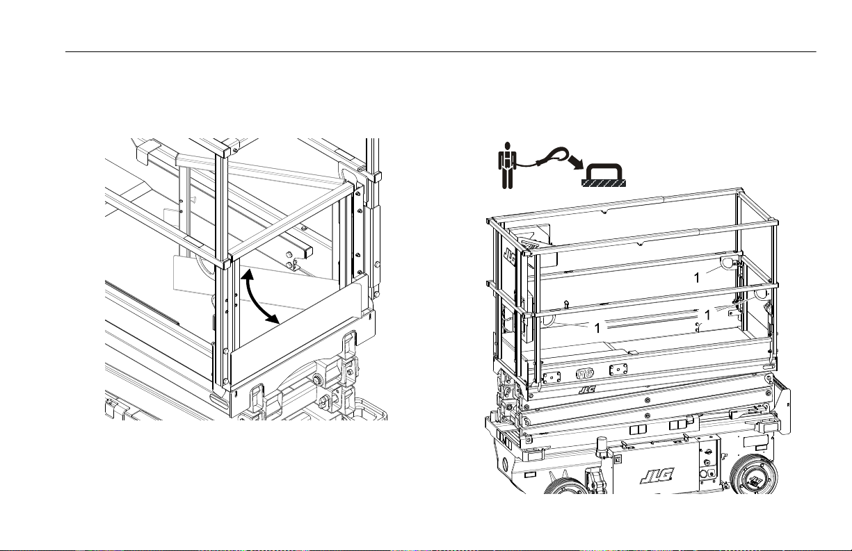
10. Platform Gate - Keep gate and surrounding area
clean and unobstructed. Check that gate closes and
latches securely and is not bent or damaged. During
operation keep gate closed.
Self-Closing Swing Gate
11. Lanyard Anchorage Points - JLG Industries, Inc. recommends personnel in the platform wear a full body
harness with a lanyard attached to an authorized lanyard anchorage point (1).
3121684 – JLG Lift – 2-5
Page 28

SECTION 2 - USER RESPONSIBILITIES, MACHINE PREPARATION AND INSPECTION
NOTICE
2.4 DAILY WALK-AROUND INSPECTION
Begin the “Walk-Around Inspection” at item 1, see Figure 2-1. on
page 2-7. Continue checking each item in sequence for the conditions listed in the following checklist.
TO AVOID POSSIBLE INJURY, BE SURE MACHINE POWER IS “OFF”. DO NOT
OPERATE UNTIL ALL MALFUNCTIONS HAVE BEEN CORRECTED.
DO NOT OVERLOOK VISUAL INSPECTION OF CHASSIS UNDERSIDE. CHECKING
THIS AREA MAY RESULT IN DISCOVERY OF CONDITIONS WHICH COULD CAUSE
EXTENSIVE MACHINE DAMAGE.
INSPECTION NOTE: On all components, make sure there are no
loose or missing parts, that they are securely fastened, and that
no visible damage, leaks or excessive wear exists in addition to
any other criteria mentioned.
1. Frame/Chassis - See Inspection Note. Also ensure that
pothole-protection components on frame are in place,
undamaged, not bent or worn.
2. Ground Controls - Placard secure and legible, control
switches return to neutral position, emergency stop
switch functions properly. Control markings legible.
3. Hydraulic Pump/Motor, Control Valve Installation - No
unsupported wires or hoses; no damaged or broken
wires - See Inspection Note.
4. Front Wheels - Steer linkage, and Steer Cylinder - See
Inspection Note.
5. Battery Compartment - See Inspection Note.
6. Rear Wheels, Tires and Drive Motors - Properly
secured, no missing lug nuts. Refer to Section 5.7,
TIRES AND WHEELS. Inspect wheels for damage and
corrosion - See Inspection Note.
7. Manual Descent Control - See Inspection Note.
8. Beacon (if equipped) - See Inspection Note.
9. Scissor Arms, Pivot Pins and Sliding Wear Pads, Lift Cyl-
inder - See Inspection Note.
10. Platform/Handrail/Gate Installation - Deck extension
slides in and out and locks in place properly. Gate
closes and latches properly. All handrails in place and
secure - See Inspection Note.
11. Platform Control Console - Ensure that the control
console is firmly secured in the proper location. Placards secure and legible, control lever and switches
return to neutral, and emergency stop switch function
properly, required manuals in storage box.
2-6 – JLG Lift – 3121684
Page 29

SECTION 2 - USER RESPONSIBILITIES, MACHINE PREPARATION AND INSPECTION
Figure 2-1. Daily Walk-Around Inspection (Side Covers Removed)
3121684 – JLG Lift – 2-7
Page 30

SECTION 2 - USER RESPONSIBILITIES, MACHINE PREPARATION AND INSPECTION
2.5 FUNCTION CHECK
Perform the Function Check as follows:
1. From the Ground Control Panel with no load in the
platform:
a. Ensure that the key selector switch and the plat-
form lift switch operates properly.
b. Ensure that all machine functions are disabled
when the Emergency Stop Button is depressed.
c. With platform raised a few feet (1m), ensure that
the manual descent control (located at the right
rear of the machine), lowers the platform properly.
d. Operate all functions and check all limiting and
cutout switches (See Figure 2-2. on page 2-10).
Check that pot-hole-protection system bars are
fully lowered when the platform is raised.
.
Platform Elevated - Pot-Hole Bars Fully Lowered
Platform Fully Lowered - Pot-Hole Bars Raised
Pot-Hole-Protection System - Operation
2. From the Platform Control Console:
a. Ensure that the control console is firmly secured
in the proper location.
b. Ensure that all guards protecting switches are in
place.
c. Operate all functions, drive/lift mode select
switch, and horn button.
d. Operate all platform joystick functions to ensure
proper operation of drive, lift, steer, and enable
trigger switch operation. Machine should not
2-8 – JLG Lift – 3121684
Page 31

SECTION 2 - USER RESPONSIBILITIES, MACHINE PREPARATION AND INSPECTION
drive with the platform above elevation unless
the pot-hole-protection system is fully lowered.
e. With the platform elevated on a smooth, firm,
level surface with no overhead obstructions, drive
the machine to check if the high drive cutout
speed-limit is engaged at the height indicated in
Table 2-2. Ensure drive speed is reduced from a
higher speed to a slower speed. Limit switch locations shown in Figure 2-2. on page 2-10.
Table 2-2. High Drive Speed Cutout Height
MODEL
R6 1.5m (59 in.)
HIGH DRIVE SPEED
CUTOUT HEIGHT
DRIVE SPEED REDUCTION
4.0 kph (2.5 mph) to
0.8 kph (0.5 mph)
f. Ensure that all machine functions are disabled
when the platform Emergency Stop Button is
depressed.
3. With the platform in the transport (stowed) position.
a. Drive the machine on a grade, not to exceed the
rated gradeability, and stop to ensure the drive
motor brakes hold.
b. Check the tilt indicator light to ensure proper
operation. The light should be illuminated if tilted
beyond allowed settings in Table 2-3.
NOTE: When the tilt indicator warning is activated the following
functions are affected;
Platform Lowered: Only Drive Allowed.
Platform Raised: Drive and lift up functions are disabled,
platform must be fully lowered (stowed) to drive out of tilt
condition.
Table 2-3. Tilt Activation Setting - Australia
MODEL
TILT SETTING
(front to back)
TILT SETTING
(side to side)
Maximum Deck Elevation
1.5° 5.64 m (Full) 18.5 ft.
R6 3°
2° 5.2 m 17 ft.
3° 4.6 m 15 ft.
3121684 – JLG Lift – 2-9
Page 32

SECTION 2 - USER RESPONSIBILITIES, MACHINE PREPARATION AND INSPECTION
Figure 2-2. Machine Switch Locations
1. Platform Elevation Switch 2. LSS Scissor Arm - Rotary Angle Switch 3. Pot-Hole-Protection System Switches
2-10 – JLG Lift – 3121684
Page 33

SECTION 3 - MACHINE CONTROLS, INDICATORS AND OPERATION
NOTICE
SECTION 3. MACHINE CONTROLS, INDICATORS AND OPERATION
3.1 GENERAL
THE MANUFACTURER HAS NO DIRECT CONTROL OVER MACHINE APPLICATION AND OPERATION, THE USER AND OPERATOR ARE RESPONSIBLE FOR
CONFORMING WITH GOOD SAFETY PRACTICES.
This section provides the necessary information needed to
understand controls and their functions.
DO NOT RAISE PLATFORM EXCEPT ON A SMOOTH, FIRM AND LEVEL SURFACE
FREE OF OBSTRUCTIONS AND HOLES.
TO AVOID SERIOUS INJURY, DO NOT OPERATE MACHINE IF ANY CONTROL
LEVERS OR TOGGLE SWITCHES CONTROLLING PLATFORM MOVEMENT DO NOT
RETURN TO THE OFF OR NEUTRAL POSITION WHEN RELEASED.
IF THE PLATFORM DOES NOT STOP WHEN A CONTROL SWITCH OR LEVER IS
RELEASED, USE THE EMERGENCY STOP SWITCH TO STOP THE MACHINE.
3121684 – JLG Lift – 3-1
3.2 DESCRIPTION
This machine is a self-propelled aerial work platform on top of
an elevating scissor arm mechanism. The Lift’s intended purpose is to position personnel with their tools and supplies at
positions above ground level. The machine can be used to reach
work areas located above machinery or equipment positioned
at ground level.
This JLG Lift has a primary operator control station in the platform. From this control station, the operator can drive and steer
the machine in both forward and reverse directions, raise and
lower the platform.
The machine can be driven on a smooth, firm, and level surface
from an elevated platform position - Reference “Steering And
Traveling” on page 3-15. of this manual for specific requirements.
The machine also has a ground control station which can override the platform control station. Ground controls operate lift up
and down. Ground controls are to be used only in an emergency
to lower the platform to the ground should the operator in the
platform be unable to do so.
Page 34

SECTION 3 - MACHINE CONTROLS, INDICATORS AND OPERATION
3.3 OPERATING CHARACTERISTICS AND LIMITATIONS
General
A thorough knowledge of the operating characteristics and limitations of the machine is always the first requirement for any
user, regardless of user’s experience with similar types of equipment.
Placards
Important points to remember during operation are provided at
the control stations by DANGER, WARNING, CAUTION, NOTICE,
and INSTRUCTION placards. This information is placed at various
locations for the express purpose of alerting personnel of
potential hazards constituted by the operating characteristics
and limitations of the machine. See foreword for definitions of
placard safety signal words.
3.4 PLATFORM LOADING
The platform maximum rated load capacity is shown on a placard located on the platform billboard and ground control station and is based upon the machine positioned on a smooth,
firm, and level surface. Refer to Section 5, Table 5-2 on page 5-3,
for the maximum platform capacity.
The platform is entered through an entry gate at the rear of the
platform. Keep entry gate closed during machine operation.
NOTE: It is important to remember that the load should be
evenly distributed on the platform. The load should be
placed near the center of the platform when possible.
3-2 – JLG Lift – 3121684
Page 35

3.5 MACHINE CONTROL LOCATIONS
SECTION 3 - MACHINE CONTROLS, INDICATORS AND OPERATION
1. Ground Control Station
2. Platform Control Station
3. Platform Manual Descent Control
4. AC Plug - To Platform AC Receptacle Outlet Box
5. AC Plug - Battery Charger Input Plug
Figure 3-1. R6 - Location of Machine Controls.
3121684 – JLG Lift – 3-3
Page 36

SECTION 3 - MACHINE CONTROLS, INDICATORS AND OPERATION
GREEN (ON) Battery Fully Charged
AMBER (ON) Battery Charging
AMBER (FLASHING) Battery/System
Problem
RED (FLASHING) Charger Problem
GREEN
AMBER
RED
LEDS
3.6 BATTERY CHARGING
through the opening on the rear panel where the
charger AC cord is accessed.
NOTE: Be sure that machine is parked in a well ventilated area
before charging begins.
4. The batteries are fully charged when the green light
on the battery charger status panel is illuminated.
NOTE: If the charger is left plugged in, the charger will automati-
ONLY PLUG THE CHARGER INTO A PROPERLY INSTALLED AND GROUNDED
OUTLET. DO NOT USE GROUND ADAPTORS OR MODIFY PLUG. DO NOT TOUCH
NON-INSULATED PORTION OF OUTPUT CONNECTOR OR NON-INSULATED
cally restart a complete charge cycle if the batteries voltage drops below a minimum voltage or 30 days has
elapsed.
BATTERY TERMINAL.
DO NOT OPERATE CHARGER IF THE AC SUPPLY CORD IS DAMAGED OR IF THE
CHARGER HAS RECEIVED A SHARP BLOW, BEEN DROPPED, OR OTHERWISE
DAMAGED IN ANY WAY.
ALWAYS DISCONNECT THE CHARGER AC SUPPLY BEFORE MAKING OR BREAKING THE (POS/NEG) CONNECTIONS TO THE BATTERY.
DO NOT OPEN OR DISASSEMBLE CHARGER.
1. The battery charger AC input plug is located in an
opening on the panel at the lower rear of the machine.
2. Connect the charger AC input plug to a grounded outlet using a 3 wire heavy duty extension cord. (See
Table 5-6, “Electrical System Specifications,” on page 55, for battery charger AC input specifications.)
3. When powered up the charger will go through a short
LED indicator self-test. The battery charger LED indicators on the charger (Figure 3-2.), will flash in sequence
for two seconds. These LED indicators can be viewed
3-4 – JLG Lift – 3121684
Figure 3-2. Charger Decal LED Indicators
Page 37

SECTION 3 - MACHINE CONTROLS, INDICATORS AND OPERATION
Battery Charger Fault (LED Flash)
If a fault has occurred during battery charging, the (AMBER or
RED) LED on the charger LED indicator (See Figure 3-2.) will flash
corresponding to the fault which occurred. Refer to Table 3-1
following for the charger LED flash codes and their meaning.
Table 3-1. Battery Charger Fault (LED Flash)
FLASHING LED FAULT REMEDY
AMBER Battery High Voltage
AMBER Batte ry Low Voltage
AMBER Failed Trickle to min V
RED Charger Internal Fault Signals a hardware fault of the charger and shall indicate flashing red LED.
Upon battery voltage >2.5V per cell @ startup, charger shall flash amber LED and not
allow charging - Battery or System problem.
Upon battery voltage <0.17V per cell @ startup, charger shall flash amber LED and
not allow charging - Battery or System problem.
Should battery fail to reach 1.75V per cell charge shall flash an amber LED until charger is power cycled - Battery or System problem.
If required, further general and troubleshooting information
about the battery charger can be found in the charger manufacturers Owner’s Guide.
3121684 – JLG Lift – 3-5
Page 38

SECTION 3 - MACHINE CONTROLS, INDICATORS AND OPERATION
1001132360A
1
2
3
4
5
1001146979A
3.7 GROUND CONTROL STATION
DO NOT OPERATE FROM GROUND CONTROL STATION WITH PERSONNEL IN
THE PLATFORM EXCEPT IN AN EMERGENCY.
PERFORM AS MANY PRE-OPERATIONAL CHECKS AND INSPECTIONS FROM
THE GROUND CONTROL STATION AS POSSIBLE.
1. Platform Lift/Lower Switch
2. Key Selector Switch
Figure 3-3. Ground Control Station
4. MDI - Indicator
5. Overload Indicator
3. Ground Emergency Stop Button
3-6 – JLG Lift – 3121684
Page 39

SECTION 3 - MACHINE CONTROLS, INDICATORS AND OPERATION
1
2
3
Ground Emergency Stop Switch - (Item 3 - Figure 3-3.)
Power is turned on by pulling the switch out, and is turned off
by depressing switch. A two-position, red, mushroom-shaped
emergency stop switch, when positioned to ON with the key
selector switch positioned to ground, furnishes operating
power to the ground control station key switch. In addition, the
switch can be used to turn off power to the function controls in
the event of an emergency.
Key Selector Switch - (Item 2 - Figure 3-3.)
The key selector switch on the
Ground Control Station functions to direct electrical power
to the desired control station.
With the switch turned to the
ground position (1), power is
supplied to the controls at the
ground control station. When
the switch is turned to the
platform position (2), power
is supplied to the controls at
the platform control station. The switch should be set to the
OFF position (3) when parking the machine overnight.
Platform Lift/Lower Switch - (Item 1 - Figure 3-3.)
A three position, momentary contact lift control switch provides
raising and lowering of the platform from the Ground Control
Station.
When operating platform from the ground controls -
Toggle the lift/lower switch to up position and hold to raise platform, or down position and hold to lower an elevated platform.
Release to center position to stop all movement.
MDI-Indicator - (Item 4 - Figure 3-3.)
The MDI indicator or Multifunction Digital Indicator displays a
Battery Discharge Indicator (BDI), an LCD display which shows
the current hour meter reading or Diagnostic Trouble Code(s)
(DTC) when a functional problem occurs with the machine, and
a system distress LED.
When a problem occurs (DTC Code displayed):
A wrench Icon (item 1) will display on the Diagnostic Trouble
Code LCD display (item 2). (See Figure 3-4.)
• A three to five digit DTC code will display on the Diagnostic
Trouble Code LCD display (item 2), below the wrench
icon.
• The system distress LED indicator (RED) (item 3) lights up
solid on the MDI when a DTC Code is displayed on the LCD
display.
3121684 – JLG Lift – 3-7
Page 40

SECTION 3 - MACHINE CONTROLS, INDICATORS AND OPERATION
1
2
3
7
6
5
4
NOTE: When more than one DTC exists, each DTC will be dis-
Also located on the MDI are Battery Discharge Indicators
(BDI) (items 4 thru 7). (4) GREEN LEDs indicate the level of
charge (voltage) remaining in the batteries.
NOTE: When the battery voltage is low and will need a charge
Under normal operating conditions the BDI’s and hour-meter
will be displayed. When a DTC exists (other than 00x
BDI LEDs and hour-meter will not be displayed. Also when platform is elevated and the machine is being driven the creep
mode (turtle) is displayed.
played on the LCD for 3 seconds before changing to the
next DTC. Once the last active DTC is displayed, the display
will recycle indefinitely until the DTC’s are corrected.
For DTC’s and descriptions, refer to Section 5.9.
soon, the LED (item 4) in the 0-25% range "red area" will
flash.
DTC’s) the
Figure 3-4. MDI Indicator
1. Hour meter, Wrench, Creep Icon Indicators
2. Hour meter/DTC Code Display
5. 50% Charge Indicator (YELLOW AREA)
6. 75% Charge Indicator (GREEN AREA)
7. 100% Charge Indicator (GREEN AREA)
3. System Fault LED Indicator (RED LED)
4. 0-25% Charge Indicator (RED AREA)
3-8 – JLG Lift – 3121684
Overload Indicator - Indicates the platform has been overloaded. An audible alarm will also signal when the platform is
overloaded.
NOTE: If the Overload Indicator is illuminated, all functions will
be prevented from the platform controls. Reduce the
weight in the platform to not exceed the rated workload
indicated on the capacity decal, or fully lower the platform using the ground controls, or manual descent.
Overload Indicator - (Item 5 - Figure 3-3.)
Page 41

SECTION 3 - MACHINE CONTROLS, INDICATORS AND OPERATION
Platform Manual Descent Control
The platform manual descent control is used in the event of
total power failure to lower the platform using gravity. The manual descent control T-handle is located on the right rear of the
machine, just in front of the drive wheel.
The lowering procedure is as follows:
1. Locate the manual descent control T-handle.
(See Figure 3-5.)
KEEP HANDS AND ARMS OUT OF THE PATH OF THE SCISSOR ARMS AND PLATFORM WHILE LOWERING.
2. Grasp the T-handle and slowly pull out to lower the
scissor arms/platform, when the platform is lowered
to desired level, allow the T-handle to return to it’s
closed position.
Figure 3-5. Location of Manual Descent Control
(Right Rear of Machine)
3121684 – JLG Lift – 3-9
Page 42

SECTION 3 - MACHINE CONTROLS, INDICATORS AND OPERATION
3.8 SCISSOR ARM - SAFETY PROP
NEVER WORK UNDER AN ELEVATED PLATFORM UNTIL IT HAS BEEN
RESTRAINED FROM MOVEMENT WITH THE SAFETY PROP, BLOCKING OR
OVERHEAD SLING.
The safety prop is located at the rear of the machine on the rod
end of the lift cylinder, located between the scissor arms.
To engage the safety prop:
1. From the Ground Control Station, raise the platform
far enough to allow the safety prop to be engaged on
the lift cylinder rod.
2. Pull out/up on the stop handle to release the safety
prop locking pin.
3. Rotate the prop assembly until it rests on the lift cylinder rod.
4. Lower the platform until the safety prop rests against
the head of the lift cylinder, stopping all downward
movement of the platform/scissor arm assembly.
To release the safety prop:
1. Raise the platform enough to release the safety prop
off the head of the cylinder.
2. Pull the prop handle downward to restore the prop
back to its released position.
3. Ensure the locking pin to hold the safety prop in the
released position is engaged.
Prop Engaged
Figure 3-6. R6 - Scissor Arm - Safety Prop
3-10 – JLG Lift – 3121684
Page 43

Prop Released and Locked
Figure 3-6. R6 - Scissor Arm - Safety Prop
SECTION 3 - MACHINE CONTROLS, INDICATORS AND OPERATION
3121684 – JLG Lift – 3-11
Page 44

SECTION 3 - MACHINE CONTROLS, INDICATORS AND OPERATION
1001132362 B
1
3
4
8
9
10
2
5
1
2
6
7
11
3.9 PLATFORM CONTROL STATION
1. Steer Control Switch
2. Drive and Lift Joystick Control
3. Tri gge r Sw itc h
4. Forward/Reverse/Lift/Lower Direction Decal
5. Alarm
6. Overload Indicator
7. Machine Tilt Indicator
8. Emergency Stop Switch
9. Horn Button
10. Drive and Lift Select Switch
11. Low Battery Charge and
System Fault Indicator
Figure 3-7. Platform Control Station.
3-12 – JLG Lift – 3121684
Page 45

SECTION 3 - MACHINE CONTROLS, INDICATORS AND OPERATION
1001132362 B
Platform Emergency Stop Switch - (Item 8 - Figure 3-7.)
NOTE: Both the ground and platform emergency stop buttons
must be set to ON in order to operate the machine.
When power is directed to the platform from the ground control
station, the platform emergency stop switch is turned on by
pulling the switch out (on), and is turned off by pushing the
switch in (off). The two-position, red, mushroom-shaped emergency stop switch functions to provide power to the platform
control station and also to turn off power to machine functions
in the event of an emergency.
Lift/Drive Select - (Item 10 - Figure 3-7.)
NOTE: When selecting between the Lift and Drive functions the
joystick control must be returned to the neutral position
for approximately 1/2 second before the function change
is operable.
This toggle switch is used to select operation of either the drive
or lift function. After selecting a function, the joystick controller
must be moved in the proper direction in order to activate that
function. Only change the function selected, with the joystick in
the neutral position. Otherwise, the function selected will not
change until the joystick is returned to the neutral position.
Forward/Reverse/Lift/Lower Direction Decal - (Item 4 - Figure 3-7.)
This decal indicates the proper direction to
mount the platform control box, the black
arrow must point to the front of the machine.
The black/white arrow also indicates the
direction to move the joystick control per the
lift/drive selector switch decal for the lift and drive select functions.
3121684 – JLG Lift – 3-13
Page 46

SECTION 3 - MACHINE CONTROLS, INDICATORS AND OPERATION
2
3
1
Drive/Lift/Steer Joystick Control
Figure 3-8. Platform Control Components
1. Trigger Switch
2. Steer Switch
1. Trigger Switch - This switch is located on the front of
the joystick controller. The trigger switch acts as an
enable and must be depressed before operating the
drive, steer and lift functions. When released, the function being operated will stop.
NOTE: Once the trigger switch is pressed, the operator has (5)
seconds to begin operating a function, after 5 seconds you
must release the trigger switch and press it again to operate a joystick function.
The speed on all selected functions is proportionally controlled by the distance from the neutral (center) position
of the joystick controller.
2. Steer Switch - The steer switch is a thumb operated
switch located at the top of the control handle.
Depressing the switch to the right will steer the
wheels to the right. Depressing the switch to the left
will steer the wheels to the left.
3. Joystick Controller - The control handle controls
three functions: drive, lift, and steer.
3. Joystick Controller
3-14 – JLG Lift – 3121684
Page 47

SECTION 3 - MACHINE CONTROLS, INDICATORS AND OPERATION
Steering And Traveling
DO NOT DRIVE WITH PLATFORM RAISED EXCEPT ON A SMOOTH, FIRM AND
LEVEL SURFACE FREE OF OBSTRUCTIONS AND HOLES.
TO AVOID LOSS OF TRAVEL CONTROL OR UPSET ON GRADES AND SIDESLOPES,
DO NOT DRIVE MACHINE ON GRADES OR SIDESLOPES EXCEEDING THOSE
SPECIFIED IN TABLE 5-1 ON PAGE 5-2.
BEFORE DRIVING, LOCATE THE DECALS WITH THE BLACK/WHITE ORIENTATION ARROWS ON THE CHASSIS AND THE PLATFORM CONTROLS. MOVE THE
JOYSTICK IN THE DIRECTION OF THE BLACK OR WHITE ARROW THAT
MATCHES THE COLOR OF THE ARROW ON THE CHASSIS FOR THE INTENDED
DIRECTION OF TRAVEL.
IF THE TILT INDICATOR WARNING LIGHT/ALARM IS ACTIVATED WHILE DRIVING WITH PLATFORM RAISED, LOWER PLATFORM COMPLETELY AND DRIVE
TO A FIRM LEVEL SURFACE.
PLACE KEY SELECTOR SWITCH AT THE GROUND CONTROL STATION TO PLATFORM OPERATION.
1. Position emergency stop switches, one at the platform
control and one at the ground control station to the
ON position.
Steering
(Item 2 - Figure 3-8.)
On the platform control station, position the
lift/drive select switch to the drive position.
To steer the machine, press the thumb operated steer rocker-switch on the joystick handle to the right for steering right, or to the
left for steering left. When released, the switch will return to the
center-off position and the wheels will remain in the previously
selected position. To return the wheels to the center position,
the switch must be activated in the opposite direction until the
wheels are centered.
Traveling Forward and Reverse
(Item 1 and 3 - Figure 3-8.)
Position the platform lift/drive
select switch (Item 10 - Figure 3-7.
on page 3-12) to drive/steer position. Squeeze the trigger switch
on front of the joystick, and
move the joystick forward to
drive forward or backward to drive in reverse. The drive system
is proportional, for additional drive speed push the joystick further from the neutral position in the direction of travel. Releasing the trigger switch or returning the joystick to center will
stop machine movement.
3121684 – JLG Lift – 3-15
Page 48

SECTION 3 - MACHINE CONTROLS, INDICATORS AND OPERATION
Figure 3-9. Grade and Sideslope Definition
3-16 – JLG Lift – 3121684
Page 49

SECTION 3 - MACHINE CONTROLS, INDICATORS AND OPERATION
Raising And Lowering Platform
1. If the machine was shut down, place the key selector
switch to the desired position (platform or ground).
2. Position emergency stop switches, one at the platform
and one at the ground control station to the ON position.
3. Position the lift/drive
select switch to lift.
(Item 10 - Figure 3-7.)
4. Squeeze and hold the
trigger switch, and
move the joystick back
(platform up - white arrow direction) or move the joystick forward (platform down - black arrow direction)
and hold until desired elevation is reached. Releasing
the trigger switch or moving the joystick back to it’s
center position will stop the function being operated.
(Item 1 and 3 - Figure 3-8.)
NOTE: To ensure proper operation of the desired platform func-
tion, move the joystick in the direction of the black or
white arrow that matches the color of the arrow on the
chassis for the intended direction of travel.
Overload Indicator -
(Item 6 - Figure 3-7.)
Indicates the platform has been overloaded. An audible alarm will also signal
when the platform is overloaded.
NOTE: If the Overload Indicator is illuminated, all functions will
be prevented from the platform controls. Reduce the
weight in the platform to not exceed the rated workload
indicated on the capacity decal, or fully lower the platform using the ground controls, or manual descent.
Tilt Indicator Warning Light and Alarm
(Item 7 - Figure 3-7.)
A red warning light on the control panel illuminates and an audible alarm sounds when
the chassis is at or beyond the tilt cutout settings.
IF THE TILT INDICATOR WARNING LIGHT/ALARM IS ACTIVATED WHEN PLATFORM IS RAISED LOWER PLATFORM AND DRIVE TO A SMOOTH FIRM LEVEL
SURFACE.
3121684 – JLG Lift – 3-17
Page 50

SECTION 3 - MACHINE CONTROLS, INDICATORS AND OPERATION
Horn
(Item 9 - Figure 3-7.)
This push-button switch, when pressed, permits the operator to warn job site personnel
when the machine is operating in the area.
Low Battery Charge and System Fault Indicator
(Item 11 - Figure 3-7.)
This indicator light comes on and stays lit
when the battery charge level is very low,
indicating the batteries will need recharging
soon.
When indicator light is flashing a system fault has occurred,
possibly stopping machine operation. Check the MDI indicator
on the Ground Control Station to see if a (DTC) Diagnostic Trouble Code(s) is displayed. An explanation of DTC codes is shown
in Section 5.9.
If the code cannot be cleared by the operator, the machine will
require service by a qualified JLG mechanic.
Alarm
(Item 5 - Figure 3-7.)
This alarm mounted on the front of the platform control station
will sound for various machine conditions or warnings such as,
system ready chirp or if the machine tilt warning is activated.
3-18 – JLG Lift – 3121684
Page 51

SECTION 3 - MACHINE CONTROLS, INDICATORS AND OPERATION
3.10 PLATFORM EXTENSION
(See Figure 3-10.)
This machine is equipped with an extension deck, giving the
operator better access to certain work areas. The deck extension
adds length to the front of the platform.
FOR MAXIMUM CAPACITY OF THE DECK EXTENSION SEE SECTION 5, TABLE 52 OR REFER TO THE CAPACITY PLACARD ON THE PLATFORM BILLBOARD.
DO NOT “LOWER” WITHOUT COMPLETELY RETRACTING THE PLATFORM
EXTENSION.
To extend t h e deck:
1. Pull up on the locking pin (1) on left side mid-rail near
the front of the machine. Rotate pin 90° to hold in up
position.
2. Grasp the top handrails (2) of the extendible deck
and push the extension out until it hits the stops.
3. Re-engage the locking pin (1) and move platform
extension in or out until the locking pin engages.
To retract the deck:
1. Pull up on the mid-rail locking pin (1) and turn the pin
90° to hold in up position.
2. Pull the extension deck all the way back into the main
deck using the top handrail (2).
3. Re-engage the mid-rail locking pin (1) back to the
locked position and engage the hole in the mid-rail.
Figure 3-10. Platform Deck Extension
3121684 – JLG Lift – 3-19
Page 52

SECTION 3 - MACHINE CONTROLS, INDICATORS AND OPERATION
NOTICE
1001132362 B
1
2
3.11 PARKING AND STOWING MACHINE
1. Drive the machine to a well-protected and well-ventilated area.
2. Ensure the platform is fully lowered.
WHEN THE MACHINE IS SHUT DOWN FOR OVERNIGHT PARKING OR BATTERY
CHARGING, THE EMERGENCY STOP AND POWER SELECT SWITCHES MUST BE
POSITIONED TO OFF TO PREVENT DRAINING THE BATTERIES.
3. At the ground control station, turn the platform ground selector key switch to OFF and remove the key
to disable the machine and prevent unauthorized use.
NOTE: For added protection, the platform control station can be
secured to it’s mounting plate see Figure 3-11.
4. At the ground control station, depress emergency
stop switch to the off position.
5. If necessary, cover the platform control box, instruction placards, caution and warning decals so that they
will be protected from hostile environment.
6. Chock at least two wheels when parking the machine
for an extended period of time.
To prevent unauthorized removal, the platform control station can be secured to it’s mount by replacing the lock pin
located on it’s mounting tab with a keyed or combination
lock.
Figure 3-11. Securing Control Station to Platform
3-20 – JLG Lift – 3121684
Page 53

SECTION 3 - MACHINE CONTROLS, INDICATORS AND OPERATION
Anti-Vandalism Package - Option
The anti-vandalism package adds hinged metal covers for the
platform and ground control stations. These hinged metal
cover are also provided with a lock tab for adding a lock to
prevent unauthorized operation of the machine when parked
and stored overnight, or for extended periods.
Platform Ground
Platform - Anti-Vandalism Package - Covers Closed
Platform Ground
Platform - Anti-Vandalism Package - Covers Open
3121684 – JLG Lift – 3-21
Page 54

SECTION 3 - MACHINE CONTROLS, INDICATORS AND OPERATION
3.12 MACHINE LIFTING AND TIE DOWN
Lifting
The machine may be lifted using a fork lift truck. Lift only from
the rear of the machine and only with the platform in the
stowed position. Adjust the width of the forklift truck, lifting
tines (1) to properly fit the machine, see Figure 3-12.
The machine can also be lifted using a spreader bar and four
equal length straps or chains capable of supporting the full
gross weight of the machine, see Figure 3-13. Lift only using the
lifting lugs provided at the four corners of the machine. (See Sec-
tion 5.2 for machine gross weight).
LIFTING THE MACHINE FROM THE SIDES USING A FORK TRUCK IS NOT RECOMMENDED BY JLG. IN THE EVENT THAT THE MACHINE NEEDS TO BE LIFTED
FROM THE SIDES CAUTION MUST BE USED TO AVOID JAMMING THE POT HOLE
PROTECTION BARS UP AGAINST THE FRAME.
EVERY TIME THE MACHINE IS LIFTED FROM THE SIDE, BE SURE AND TEST THE
POT HOLE PROTECTION SYSTEM BEFORE THE MACHINE IS PUT BACK INTO
OPERATION.
3-22 – JLG Lift – 3121684
Tie Down
When transporting the machine, the platform must be fully lowered in the stowed position with the machine securely tied
down to the truck or trailer deck. There are two tie-down/lift
lugs located at the front and rear of the machine. (See Figure 3-
14.)
Figure 3-12. Fork Lift Pockets - Location
Page 55

SECTION 3 - MACHINE CONTROLS, INDICATORS AND OPERATION
Figure 3-13. Lifting Using Spreader Bar and Lift Lug Locations
1. Four (4) equal length chains or lifting straps. 2. Spreader Bar Assembly.
3121684 – JLG Lift – 3-23
Page 56

SECTION 3 - MACHINE CONTROLS, INDICATORS AND OPERATION
Figure 3-14. Tie Down and Lift Lug Locations
3-24 – JLG Lift – 3121684
Page 57

SECTION 3 - MACHINE CONTROLS, INDICATORS AND OPERATION
3.13 TOWING
It is not recommended that this machine be towed, except in
the event of an emergency such as a machine malfunction or a
total machine power failure.
Electric Brake Release
(See Figure 3-15.)
NOTE: Electrical release of the brakes requires enough battery
power to hold the brakes in released mode until destination is reached.
1. Chock wheels or secure machine with tow vehicle.
2. Turn power on in ground mode on the ground control station (1).
3. The brake release switch (2) is located inside the
hydraulic components side cover, remove cover to
access the switch.
4. Depress the brake release switch once to release
brakes.
5. When finished towing depress brake release switch
again or turn power off at the ground control station
to re-engage the brakes.
NOTE: Any action which causes a loss of power from the brakes
such as, depressing the ground control emergency stop
switch, or switching the key switch to OFF or PLATFORM
MODE will re-engage the brakes.
Figure 3-15. Electric Brake Release - Location
3121684 – JLG Lift – 3-25
Page 58

SECTION 3 - MACHINE CONTROLS, INDICATORS AND OPERATION
1
2
4
3
Mechanical Brake Release
(See Figure 3-16.)
CHOCK WHEELS OR SECURE MACHINE WITH TOW VEHICLE.
1. At the ground control station turn power off by pressing the Emergency Stop switch in.
2. Remove the two cover bolts (1), and the cover (2),
from the back of drive motor unit.
3. Insert the cover bolts (1) into the two disengage
holes in the brake housing (4), see Figure 3-16.,
Brake - Manual Disengage.
4. Tighten down the cover bolts (3) in the disengage
holes and the brake on that drive motor will disengage.
5. Repeat this procedure on opposite wheel drive. With
both drive motor brakes now disengaged the machine
can be moved manually.
6. After towing is complete, chock wheels and remove
cover bolts from disengage holes.
7. Reinstall cover (2) - before installation check the
cover gasket (3) for damage, replace if necessary.
AFTER THE MACHINE IS TOWED THE COVER BOLTS (1) MUST BE REMOVED
FROM THE BRAKE DISENGAGE HOLES (4). THE BRAKES CANNOT BE ENGAGED
IF THE DISENGAGE BOLTS ARE LEFT IN THE DISENGAGE HOLES. THIS WILL
CAUSE THE MACHINE TO ROLL WHEN PARKED ON AN INCLINE.
3-26 – JLG Lift – 3121684
Figure 3-16. Brake - Manual Disengage.
Page 59

SECTION 4 - EMERGENCY PROCEDURES
SECTION 4. EMERGENCY PROCEDURES
4.1 GENERAL INFORMATION
This section explains the steps to be taken in case of an emergency situation during operation.
4.2 EMERGENCY OPERATION
Operator Unable to Control Machine
IF THE PLATFORM OPERATOR IS UNABLE TO OPERATE OR CONTROL THE MACHINE:
1. Other personnel should operate the machine from
ground controls only as required.
2. Only qualified personnel in the platform may use the
platform controls. DO NOT CONTINUE OPERATION IF
CONTROLS DO NOT FUNCTION PROPERLY.
3. Rescue equipment can be used to remove the platform occupant(s). Cranes and forklifts can be used to
stabilize motion of the machine.
Platform Caught Overhead
If the platform becomes jammed or snagged in overhead structures or equipment, rescue the platform occupant(s) prior to
freeing the machine.
Righting of Tipped Machine
A fork truck of suitable capacity or equivalent equipment
should be placed under the elevated side of the chassis, with a
crane or other suitable lifting equipment used to lift the platform while the chassis is lowered by the forklift or other equipment.
4.3 PLATFORM MANUAL DESCENT
The platform manual descent control is used in the event of
total power failure to retract and lower the platform using gravity. The manual descent control T-handle is located on the right
rear of the machine, just in front of the drive wheel. Look for the
instruction decal located beside the release handle.
The lowering procedure is as follows:
1. Locate the manual descent control T-handle.
(See Figure 4-1. on page 4-2)
KEEP HANDS AND ARMS OUT OF THE PATH OF THE SCISSOR ARMS AND PLATFORM WHILE LOWERING.
2. Grasp the T-handle and slowly pull out to lower the
scissor arms/platform, when the platform is lowered
to desired level, allow the T-handle to return to it’s
closed position.
3121684 – JLG Lift – 4-1
Page 60

SECTION 4 - EMERGENCY PROCEDURES
NOTICE
Figure 4-1. Location of Manual Descent Control
(Right Rear of Machine)
4.4 INCIDENT NOTIFICATION
JLG Industries, Inc. must be notified immediately of any incident
involving a JLG product. Even if no injury or property damage is
evident, JLG must be contacted by telephone and provided
with all necessary details.
USA: 877-JLG-SAFE (554-7233)
EUROPE: (44) 1 698 811005
AUSTRALIA: (61) 2 65 811111
E-mail: productsafety@jlg.com
Failure to notify the manufacturer of an incident involving a JLG
Industries product within 48 hours of such an occurrence may
void any warranty consideration on that particular machine.
FOLLOWING ANY INCIDENT, THOROUGHLY INSPECT THE MACHINE. DO NOT
ELEVATE PLATFORM UNTIL YOU ARE SURE THAT ALL DAMAGE HAS BEEN
REPAIRED, AND THAT ALL CONTROLS ARE OPERATING CORRECTLY. TEST ALL
FUNCTIONS FIRST FROM THE GROUND CONTROL STATION, THEN FROM THE
PLATFORM CONTROL CONSOLE.
4-2 – JLG Lift – 3121684
Page 61

SECTION 5 - GENERAL SPECIFICATIONS AND MAINTENANCE
SECTION 5. GENERAL SPECIFICATIONS AND MAINTENANCE
5.1 INTRODUCTION
This section of the manual provides additional necessary information to the operator for proper operation and maintenance
of this machine.
The maintenance portion of this section is intended as information to assist the machine operator to perform daily maintenance tasks only, and does not replace the more thorough
Preventive Maintenance and Inspection Schedule included in
the Service and Maintenance Manual.
3121684 – JLG Lift – 5-1
Other Publications Available Specific to this Machine:
Service and Maintenance Manual......................................3121685
Illustrated Parts Manual .........................................................3121686
Page 62

SECTION 5 - GENERAL SPECIFICATIONS AND MAINTENANCE
5.2 OPERATING SPECIFICATIONS
Table 5-1. Operating Specifications
DESCRIPTION R6
PLATFORM
Maximum Platform Height 5.79 m (19 ft.)
DRIVING
Ma x im u m D r iv e S p ee d Sto wed:
Maximum Stowed Travel Grade (Gradeability)
(Reference Figure 3-9. on page 3-16)
Inside Turning Radius 0.6 m (23.6 in.)
Outside Turning Radius 2.22 m (87.9 in.)
CHASSIS
Approximate Gross Machine Weight 1,588 kg (3,500 lb.)
Maximum Tire Load (per wheel) 620 kg (1,365 lb.)
Ground Bearing Pressure 9.18 kg/cm
Ground Clearance (Pot-Hole Stowed - Center)) 95.5 mm (3.75 in.)
Wheelbase 1397 mm (55 in.)
Ma x i m um H yd r a ul i c Pr e ss u re M ai n / Li f t Re l i ef :
Elevated:
Steer Relief:
4.0 kph (2.5 mph)
0.8 kph (0.5 mph)
25% (14°)
2
(130 PSI)
159 bar (2300 psi)
69 bar (1000 psi)
5-2 – JLG Lift – 3121684
Page 63

Platform Capacities
SECTION 5 - GENERAL SPECIFICATIONS AND MAINTENANCE
Table 5-2. Platform Capacities
MAXIMUM
SPECIFICATION MACHINE MODEL
AUSTRALIA R6 230 Kg 120 Kg Indoor - 2 Persons + 70 Kg 400 N 0 m/s
NOTE: (1) Maximum Platform Capacity includes platform and platform extension.
3121684 – JLG Lift – 5-3
PLATFORM
CAPACITY
MAXIMUM CAPACITY
(1)
ALLOWED ON
PLATFORM EXTENSION
MAXIMUM PERSONS
ALLOWED IN PLATFORM
Outdoor - 1 Person + 150 Kg 200 N 12.5 m/s
MAX. SIDE FORCE
(Platform Fully Extended
@ Max. Capacity)
MAXIMUM
OPERATING
WIND SPEED
Page 64

SECTION 5 - GENERAL SPECIFICATIONS AND MAINTENANCE
Machine Dimensional Data Tires
Table 5-3. Dimensions
Table 5-4. Tire Specifications
DESCRIPTION R6
Platform He ight - Elevated
(Ground to Platform Floor)
Platform Height - Stowed
(Ground to Platform Floor)
Working Height 7.47 m (24 ft. 6 in.)
Rail Height
(Platform Floor to Top of Rail)
Overall Machine Width 81.2 cm (32 in.)
Overall Machine Length (w/ladder) 2.08 m (81.8 in.)
Platform Size - Length 1.82 m (71.3 in.)
Platform Size - Width 68.9 cm (27.1 in.)
Wheelbase 139.7 cm (55 in.)
5-4 – JLG Lift – 3121684
5.79 m (19 ft)
100 cm (39.5 in.)
Batteries
101.6 cm (40 in.)
Voltage (24V System - Series) 6 V per batter y
Amp Hour (Standard Battery) 22 0 Amp Hour @ 20 HR. Rate
Reserve Capacity (Standard Battery) 447 Minutes
DESCRIPTION R6
Size 323 mm x 100 mm
(12.71 in. x 3.94 in.)
Wheel Bolt Torque 163 Nm (120 ft lb.)
Table 5-5. Battery Specifications
DESCRIPTION R6
Page 65

SECTION 5 - GENERAL SPECIFICATIONS AND MAINTENANCE
Electrical System 5.3 CRITICAL STABILITY WEIGHTS
Table 5-6. Electrical System Specifications
DESCRIPTION SPECIFICATION
Electrical System Voltage (DC) 24V
Battery Charger:
Input:
AC Inp ut Volta ge:
Nominal AC Input Voltage:
Input Frequency:
Max. AC Input Current:
Ingress Protection:
Operatin g Temperature:
Output:
Nominal DC Output Voltage:
Max. DC Output Voltage:
Max DC Output Current:
Max. Interlock Current:
Protection:
Output Reverse Polarity:
Output Short Circuit:
AC Ove rloa d:
DC Overload:
DC t o A C I n ve r te r - O ut p ut R at in g :
(OPTI ON)
85-265V AC
120VAC / 230VAC RMS
45 - 65Hz
12A - RMS @ 108V AC
IP46 NEMA4 Type 4
-22°F (-30°C) to 122°F (+50°C)
24V
33.6V
25A
1A
Electronic Protection-Auto Reset
Electronic Protection-Auto Reset
Current Li mited
Current Li mited
120V-AC, 60Hz - 7.5 Amps - 900 Watts Mod. Sinewave
DO NOT REPLACE ITEMS CRITICAL TO STABILITY, SUCH AS BATTERIES OR
SOLID TIRES, WITH ITEMS OF DIFFERENT WEIGHT OR SPECIFICATION. DO
NOT MODIFY UNIT IN ANY WAY TO AFFECT STABILITY.
Table 5-7. Critical Stability Weights
COMPONENT R6
Wh e el a nd Ti r e A ss e mb l y ( ea c h) Fr on t :
Rear:
Wheel/Tire and Drive Assembly (each) 51.3 kg (113 lb.)
Batteries (each) Standard:
AGM:
Batteries (combined) Standard :
AGM:
9.8 kg (21.6 lb.)
9.8 kg (21.6 lb.)
28.1 kg (62 lb.)
29.5 kg (65 lb.)
111.1 kg (248 lb.)
118 kg (260 lb.)
3121684 – JLG Lift – 5-5
Page 66

SECTION 5 - GENERAL SPECIFICATIONS AND MAINTENANCE
5.4 LUBRICATION
Lubrication Capacities
Table 5-8. Capacities
COMPONENT R6
Hydraulic
Reservoir 5 L (1.32 Gal.)
Hydraulic System
(Including
Reservoir)
7 L (1.85 Gal.)
Hydraulic Oil
Table 5-9. Hydraulic Oil
HYDRAULIC SYSTEM OPERATING
TEMPERATURE RANGE
-18° C to -5° C (0° F to +23° F) 10W
-18° C to + 99° C (0° F to 210° F) 10W-20, 10W-30
+10° C to +99° C (50° F to 210° F) 20W-20
NOTE: Aside from JLG recommendations, it is not advisable to
mix oils of different brands or types, as they may not contain the same required additives or be of comparable viscosities.
SAE VISCOSITY GRADE
Lubrication Specifications
Table 5-10. Lubrication Specifications
KEY SPECIFICATIONS
MPG Multipurpose Grease having a minimum dripping point of 350° F. Excel-
lent water resistance and adhesive qualities, and being of extreme pressure type. (Timken OK 40 pounds minimum.)
EPGL Ex treme Pressure Gear Lube (oil) meeting API service classification GL-5 or
MI L-S pe c M IL- L-2 10 5.
HO JLG Recommends - Mobil DTE 10 EXCEL 15
ATF - Automatic Transmission Fluid
Mobil EAL ENVIRONSYN H 32
Mobil EAL HYDRAULIC OIL 32
5-6 – JLG Lift – 3121684
Page 67

Table 5-11. Hydraulic Oil Specifications
SECTION 5 - GENERAL SPECIFICATIONS AND MAINTENANCE
SPECIFICATION
MOBIL
DTE 10
EXCEL 15
MOBIL EAL
ENVIRONSYN
H 32
MOBIL EAL
HYDRAULIC OIL 32
ISO Viscosity Grade #15 #32 #32
Spec Gravity API 31.9 0.950 —
Pour Point, Max
-40° C
(-40° F)
-51° C
(-59° F)
-39° C
(-38.2° F)
Flash Point, Min. 166° C (330° F) 268° C (514.4° F) 248° C (478° F)
VISCOSITY SPECIFICATIONS
at 40° C 15 cSt
at 100° C 4.1 cSt
at 100° F 80 SUS
at 210° F 43 SUS
cp at -30° F 3.2
33.1 cSt 32 cSt
6.36 cSt 7 cSt
——
——
——
Viscosity Index 140 147 189
Operating Temp — 29° C(-20° F ) - 93° C (200° F)
1001102685_3
3121684 – JLG Lift – 5-7
Page 68

SECTION 5 - GENERAL SPECIFICATIONS AND MAINTENANCE
5.5 MAINTENANCE
Hydraulic Oil Check Procedure
Lube Point(s) - Hydraulic Reservoir
Reservoir Capacity - See Table 5-8 on page 5-6.
Lube - Hydraulic Oil
Interval - Check Daily
NOTE: Check the hydraulic oil level with the platform in the
stowed position ONLY. Be certain the hydraulic oil has
warmed to operating temperature before checking the oil
level in the reservoir.
1. On the left side of the machine, remove the side
access door on the base frame. Locate the hydraulic
oil reservoir (1) on the pump unit (2). Check the oil
level in the hydraulic reservoir by looking at the markings on the side. The reservoir is marked with a MAX
(maximum) marking (3). The oil level must be kept at
or within one (1) inch of this marking to operate properly.
2. If additional oil is required, wipe all dirt and debris
from the filler/breather cap (4) area, add proper
grade of oil. Fill until oil level is close to the MAX
marking (3), but not over the MAX marking.
NOTE: Care should be taken not to introduce any impurities (dirt,
water, etc.) while cap is removed.
Figure 5-1. Hydraulic Oil Check Procedure
NOTE: Recommended lubricating intervals are based on
machine operations under normal conditions. For
machines used in multi-shift operations and/or exposed
to hostile environments or conditions, lubrication frequencies must be increased accordingly.
5-8 – JLG Lift – 3121684
Page 69

5.6 BATTERY MAINTENANCE
1/8 "
BATTERY
FILLER CAP
FLUID LEVEL OF FULLY
CHARGED BATTERY
VENT TUBE
PLATES
1706740A
Battery Maintenance and Safety Practices
NOTE: These instructions are for unsealed (wet) batteries only.
if machine is equipped with sealed batteries, no maintenance other than cleaning corroded battery terminals is
required.
ENSURE THAT BATTERY ACID DOES NOT COME INTO CONTACT WITH SKIN OR
CLOTHING. WEAR PROTECTIVE CLOTHING AND EYEWEAR WHEN WORKING
WITH BATTERIES. NEUTRALIZE ANY BATTERY ACID SPILLS WITH BAKING
SODA AND WATER.
BATTERY ACID RELEASES AN EXPLOSIVE GAS WHILE CHARGING, ALLOW NO
OPEN FLAMES, SPARKS OR LIGHTED TOBACCO PRODUCTS IN THE AREA
WHILE CHARGING BATTERIES. CHARGE BATTERIES ONLY IN A WELL VENTILATED AREA.
ADD ONLY DISTILLED WATER TO BATTERIES. WHEN ADDING DISTILLED
WATER TO THE BATTERIES, A NON-METALLIC CONTAINER AND/OR FUNNEL
MUST BE USED.
Check the electrolyte level of the batteries often, adding only
distilled water when required. When fully charged, battery fluid
level should be 1/8" below vent tubes. (See Figure 5-2.).
• DO NOT fill to bottom of vent tubes.
• DO NOT allow fluid level to go below the top of the plates
SECTION 5 - GENERAL SPECIFICATIONS AND MAINTENANCE
Figure 5-2. Battery Fluid Level.
Battery Quick-Disconnect
Machines equipped with the battery
quick-disconnect allow all machine
power to be easily disconnected at the
batteries without removing battery
cables from the battery posts. To disconnect power, locate the RED quick-disconnect connector on top
of the batteries inside the battery compartment and pull halves
apart.
3121684 – JLG Lift – 5-9
Page 70

SECTION 5 - GENERAL SPECIFICATIONS AND MAINTENANCE
5.7 TIRES AND WHEELS
Tire Wear and Damage
The tire and rim assemblies installed on RS machines have been
approved by the tire manufacturer for applications in which
those products are intended to be used. The tire and rims
installed on each product model have been designed for stability requirements, which consist of track width, tire compound,
and load capacity. Tire changes such as rim width, centerpiece
location, larger or smaller diameter, tire compound, etc., without written manufacturers approval, could result in an unsafe
condition regarding stability.
The tires and rims installed on RS machines are to be inspected
daily as part of the daily walk-around inspection. JLG requires
that the daily walk-around inspection be performed at each
operator change during a shift and at each shift change.
Wheel and Tire Replacement
JLG recommends that any replacement tire be the same size
and brand as originally installed on the machine or offered by
JLG as an approved replacement. Please refer to the JLG Parts
Manual for the part number of the approved tires for a particular machine model.
If any of the following is discovered during tire inspection,
measures must be taken to remove the JLG product from service immediately. Arrangements must be made for replacement of the tire(s) or tire assembly(s). Both tires/wheels on the
same axle must be replaced:
• If the overall diameter of the tire is less than one of the following:
100 x 323 Tire – 311mm (12.25 in.) minimum
127 x 406 Tire – 394mm (15.50 in.) minimum
• If any uneven wear is discovered.
A tire with significant damage in the tread area or sidewall
requires immediate evaluation before placing the machine
into service. If a cut, tear, chunk, or other discrepancy
exceeds any one or more of the following dimensions, the
tire must be replaced:
76 mm (3.0 in.) long
19 mm (0.75 in.) wide
19 mm (0.75 in.) deep
• If the metal wheel is visible at any point through the tread
area of the tire.
• If more than one discrepancy exists in any quadrant of the
wheel (within 90 degrees of one another).
5-10 – JLG Lift – 3121684
Page 71

SECTION 5 - GENERAL SPECIFICATIONS AND MAINTENANCE
1
2
3
4
5
2
3
4
6
5
1
Wheel Installation
Check torque every 3 months or 150 hours of operation.
It is extremely important to apply and maintain proper wheel
mounting torque.
WHEEL LUG NUTS MUST BE INSTALLED AND MAINTAINED AT THE PROPER
TORQUE TO PREVENT LOOSE WHEELS, BROKEN LUG NUTS, AND POSSIBLE
SEPARATION OF WHEEL FROM THE AXLE. BE SURE TO USE ONLY THE LUG
NUTS MATCHED TO THE CONE ANGLE OF THE WHEEL.
Tighten the lug nuts to the proper torque to prevent wheels
from coming loose. Use a torque wrench to tighten the fasteners. Over-tightening will result in breaking the lug nuts or permanently deforming the mounting holes in the wheel. The
proper procedure for attaching wheels is as follows:
1. Start all lug nuts by hand to prevent cross threading.
Figure 5-3. Wheel Lug Nut Tightening Sequence
5 LUG WHEEL 6 LUG WHEEL
DO NOT use a lubricant on threads or nuts.
2. Tighten lug nuts in the following sequence. (See Figure
5-3.)
3. The tightening of the lug nuts should be done in
stages. Following the recommended sequence,
tighten lug nuts per wheel torque.
4. Wheel lug nuts should be torqued after the first 50
hours of operation and after each wheel removal.
3121684 – JLG Lift – 5-11
1st Stage 2nd Stage 3rd Stage
28 - 42 Nm
(20-30 ft. lb.)
Table 5-12. Wheel Torque Chart
TORQUE SEQUENCE
91 - 112 Nm
(65-80 ft. lb.)
(105 -120 ft. lb.)
142 - 163 Nm
Page 72

SECTION 5 - GENERAL SPECIFICATIONS AND MAINTENANCE
5.8 DECAL INSTALLATION
Figure 5-4. Machine Decal Installation (See Table 5-13.)
5-12 – JLG Lift – 3121684
Page 73

SECTION 5 - GENERAL SPECIFICATIONS AND MAINTENANCE
Table 5-13. Machine Decal Installation Chart
ITEM
1 0860520
2 —
3 1701504
4 1701509
5 1705754
6 1703177
7 1705670
8 1703819
9 1703822
10 1704016
11 1704277
12 1704412 (on tank)
13 1705647
14 —
15 —
16 1705673
17 1705671
18 —
19 —
AUSTRALIA
(R6)
Table 5-13. Machine Decal Installation Chart
ITEM
20 —
21 1001127512
22 1001162864
23 1001132359
24 1001146902
25 —
26 1001182601
27 1001146794
28 1001137394
29 1001134280
30 —
31 1706350
32 1703072
33 —
34 1001092497
NOTE: Reference applicable Illustrated Parts Manual for decal
description.
AUSTR ALIA
(R6)
3121684 – JLG Lift – 5-13
Page 74

SECTION 5 - GENERAL SPECIFICATIONS AND MAINTENANCE
NOTICE
5.9 DIAGNOSTIC TROUBLE CODES (DTC)
The DTC tables following are sorted in groups by the first two
digits, these digits represent the number of flashes the system
distress indicator lamp will flash on the platform indicator panel
when a fault occurs.
For example: a “2-1 Power-Up” on page 16 would be indicated
by 2 flashes, a pause, then 1 flash, a pause, then would keep
repeating until the fault is cleared.
The more detailed three digit code numbers in the DTC column
of the following tables are only indicated on a JLG handheld
diagnostic analyzer.
To troubleshoot multiple DTCs, start with the DTC with the
higher first two digits. If a correction is made during a check,
conclude the check by cycling the machine power off then
back on, using the emergency stop switch.
SHOULD A FAULT OCCUR WHICH CANNOT BE CORRECTED BY THE OPERATOR,
THE PROBLEM MUST BE REFERRED TO A MECHANIC QUALIFIED TO REPAIR
THIS MODEL OF JLG LIFT.
5.10 DTC CHECK TABLE INDEX
DTC TABLE PAGE
0-0 Help Comments. . . . . . . . . . . . . . . . . . . . . . . . . . . . . . . . . . . . . . . 5-15
2-1 Power-Up. . . . . . . . . . . . . . . . . . . . . . . . . . . . . . . . . . . . . . . . . . . . 5-16
2-2 Platform Controls . . . . . . . . . . . . . . . . . . . . . . . . . . . . . . . . . . . . . 5-17
2-3 Ground Controls . . . . . . . . . . . . . . . . . . . . . . . . . . . . . . . . . . . . . . 5-18
2-5 Function Prevented. . . . . . . . . . . . . . . . . . . . . . . . . . . . . . . . . . . . 5-18
3-1 Line Contactor Open Circuit . . . . . . . . . . . . . . . . . . . . . . . . . . . . . 5-20
3-2 Line Contactor Short Circuit . . . . . . . . . . . . . . . . . . . . . . . . . . . . . 5-21
3-3 Ground Output Driver . . . . . . . . . . . . . . . . . . . . . . . . . . . . . . . . . . 5-21
4-2 Thermal Limit (SOA) . . . . . . . . . . . . . . . . . . . . . . . . . . . . . . . . . . . 5-23
4-4 Battery Supply. . . . . . . . . . . . . . . . . . . . . . . . . . . . . . . . . . . . . . . . 5-23
6-6 Communication . . . . . . . . . . . . . . . . . . . . . . . . . . . . . . . . . . . . . . 5-24
7-7 Electric Motor . . . . . . . . . . . . . . . . . . . . . . . . . . . . . . . . . . . . . . . . 5-24
8-2 LSS - Load Sensing System . . . . . . . . . . . . . . . . . . . . . . . . . . . . . . 5-26
8-4 Elevation Switch . . . . . . . . . . . . . . . . . . . . . . . . . . . . . . . . . . . . . . 5-27
9-9 Hardware. . . . . . . . . . . . . . . . . . . . . . . . . . . . . . . . . . . . . . . . . . . . 5-27
5-14 – JLG Lift – 3121684
Page 75

SECTION 5 - GENERAL SPECIFICATIONS AND MAINTENANCE
5.11 DIAGNOSTIC TROUBLE CODES (DTC) CHECK TABLES
0-0 Help Comments
DTC FAULT MESSAGE DESCRIPTION CHECK
001 EVERYTHING OK The normal help message in platform mode.
Displays on the analyzer only.
002 GROUND MODE OK The normal help message in ground mode.
Displays on the analyzer only.
003 ALARM SOUNDING - TILTED & ABOVE
ELEVATION
004 DRIVING AT CUTBACK - ABOVE ELEVA-
TION
Control system senses that the platform is elevated and the vehicle is tilted, and the
machine not configured to cutout.
The platform is elevated and the machine is
driving in creep speed.
• Check that the machine is tilted. If so, lower the platform and reposition the
machine to a level surface.
• Fully stow the platform.
• The tilt sensor is par t of the ground control box. Check that the ground control
box is secured to the machine.
• Check that the pothole protection switches are securely mounted and properly adjusted.
• Check that the elevation angle sensor is securely mounted and properly
adjusted.
Refer problem to a qualified JLG mechanic.
• Fully stow the platform.
• Check that the elevation sensor is securely mounted, and properly adjusted.
• Check that the pothole protection switches are securely mounted, and prop-
erly adjusted.
Refer problem to a qualified JLG mechanic.
3121684 – JLG Lift – 5-15
Page 76

SECTION 5 - GENERAL SPECIFICATIONS AND MAINTENANCE
0-0 Help Comments
DTC FAULT MESSAGE DESCRIPTION CHECK
005 DRIVE & LIFT UP PREVENTED - TILTED &
ELEVATED
007 DRIVING AT CUTBACK - POTHOLE STILL
ENGAGED
008 FUNCTIONS LOCKED OUT - SYSTEM
POWERED DOWN
Driving is not possible since the platform is
elevated and the chassis is not level.
While stowed, drive speed is reduced since the
control system detected that the pothole protection mechanism failed to retract.
After 2 hours without activity, the control system enters a low-power st ate to preser ve battery c harge.
• Check that the machine is tilted. If so, lower the platform and reposition the
machine to a level surface.
• Fully stow the platform.
• Check that the tilt sensor is securely mounted.
• Check that the pothole protection switches are securely mounted and prop-
erly adjusted.
• Check that the elevation angle sensor is securely mounted and properly
adjusted.
Refer problem to a qualified JLG mechanic.
• Check for obstructions around the pot-hole protection mechanisms.
• Check that the PHP switches are securely mounted and adjusted.
Refer problem to a qualified JLG mechanic.
• Normal operation should resume after power is cycled off then back on.
• Check batteries charge, condition, etc.
Refer problem to a qualified JLG mechanic.
2-1 Power-Up
DTC FAULT MESSAGE DESCRIPTION CHECK
211 POWER CYCLE This help message is issued at each power
cycle. Displays on the analy zer only.
5-16 – JLG Lift – 3121684
Normal operation. No check necessary.
Page 77

SECTION 5 - GENERAL SPECIFICATIONS AND MAINTENANCE
2-2 Platform Controls
DTC FAULT MESSAGE DESCRIPTION CHECK
221 FUNCTION PROBLEM - HORN PERMA-
NENTLY SELECTED
223 FUNCTION PROBLEM - DRIVE & LIFT
ACTIVE TOGETHER
224 FUNCTION PROBLEM - STEER LEFT PER-
MANENTLY SELECTED
225 FUNCTION PROBLEM - STEER RIGHT
PERMANENTLY SELECTED
226 ACCELERATOR FAULTY - WIPER OUT OF
RANGE
227 STEER SWITCHES FAULTY The steer left and steer right inputs were
228 FUNCTION LOCKED OUT - ACCELERATOR
NOT CENTERED
229 FUNCTION PROBLEM - TRIGGER PER-
MANENTLY CLOSED
2210 TRIGGER CLOSED TOO LONG WHILE IN
NEUTRAL
The horn switch was closed during power-up
in platform mode.
The drive and lift inputs are closed simultaneously in platform mode.
The steer left switch was closed during powerup in platform mode.
The steer right switch was closed during
power-up in platform mode.
There is a problem with the joystick. • Center joystick and check to see if a power cycle will clear DTC.
closed simultaneously.
The joystick was not centered at power-up. • Release joystick and allow to center.
The trigger switch was closed during powerup in platform mode.
The trigger switch was closed for more than
five seconds while the joystick was centered.
• Check if the horn switch is damaged, obstructed or jammed.
Refer problem to a qualified JLG mechanic.
• Check drive/lift switch for visible damage.
Refer problem to a qualified JLG mechanic.
• Check if the steer left switch is obstructed or jammed.
Refer problem to a qualified JLG mechanic.
• Check if the steer right switch is obstructed or jammed.
Refer problem to a qualified JLG mechanic.
Refer problem to a qualified JLG mechanic.
• Check if the steer switches are damaged, obstructed or jammed.
Refer problem to a qualified JLG mechanic.
• Check if the joystick is obstructed or jammed.
Refer problem to a qualified JLG mechanic.
• Check if the trigger switch is obstructed or jammed.
Refer problem to a qualified JLG mechanic.
• Check if the trigger switch is obstructed or jammed.
Refer problem to a qualified JLG mechanic.
3121684 – JLG Lift – 5-17
Page 78

SECTION 5 - GENERAL SPECIFICATIONS AND MAINTENANCE
2-2 Platform Controls
DTC FAULT MESSAGE DESCRIPTION CHECK
2232 FUNC TION PROBLEM - DRIVE & LIFT
BOTH OPEN
The drive and lift inputs are both de-energized
in platform mode.
• Check if either function is active, if Yes;
Refer problem to a qualified JLG mechanic.
2-3 Ground Controls
DTC FAULT MESSAGE DESCRIPTION CHECK
231 FUNCTION PROBLEM - LIFT PERMA-
NENTLY SELECTED
232 GROUND LIFT UP / DOWN ACTIVE
TOGETHER
233 FUNCTION PROBLEM - BR AKE RELEASE
PERMANENTLY SELECTED
The ground control box lift switch was closed
up or down, during power-up in ground mode.
The lift up / down inputs are closed simultaneously.
The electric brake release switch was closed
during power-up.
• Check if the lift switch is obstructed or jammed.
Refer problem to a qualified JLG mechanic.
• Check if the lift switch is obstructed or jammed.
Refer problem to a qualified JLG mechanic.
• Check if the brake release switch is obstructed or jammed.
Refer problem to a qualified JLG mechanic.
2-5 Function Prevented
DTC FAULT MESSAGE DESCRIPTION CHECK
253 DRIVE PREVENTED - CHARGER CON-
NECTED
5-18 – JLG Lift – 3121684
Driving is not possible while the vehicle is
charging.
• Check if the charger is connected to off board power source and disconnect if
desired.
Refer problem to a qualified JLG mechanic.
Page 79

SECTION 5 - GENERAL SPECIFICATIONS AND MAINTENANCE
2-5 Function Prevented
DTC FAULT MESSAGE DESCRIPTION CHECK
254 DRIVE & LIFT UP PREVENTED - CHAR-
GER CONNECTED
255 PLATFORM OVERLOAD The Load Sensing System (LSS) measured
256 DRIVE PREVENTED - POT-HOLE NOT
ENGAGED
258 DRIVE & LIFT PREVENTED - BRAKES
ELECTRICALLY RELEASED FOR TOWING
259 MODEL CHANGED - HYDRAULICS SUS-
PENDED - CYCLE EMS
2510 DRIVE PREV ENTED - BRAKES NOT
RELEASING
3121684 – JLG Lift – 5-19
Drive or lift is not possible while the vehicle is
charging AND is configured to prevent all
motion.
platform load is excessive.
Driving is not possible while elevated since the
pot-hole protection system failed to deploy.
Electric brake release mode is activated with
the switch in the battery box near the ground
control box. Drive or lift is not possible.
The model selection has been changed. Refer problem to a qualified JLG mechanic.
There is a problem with the drive or brake system.
• Check if the charger is connected to off board power source and disconnect if
desired.
Refer problem to a qualified JLG mechanic.
• Remove excess weight from the platform.
• Check that platform is not caught on something, preventing up or down
movement.
Refer problem to a qualified JLG mechanic.
• Check for obstructions or mechanical problems around the pot-hole protection mechanisms.
• Check that the PHP switches are securely mounted.
Refer problem to a qualified JLG mechanic.
• Push manual brake release switch again or cycle power to clear manual brake
release mode.
• Check if the brake release switch is obstructed or jammed.
Refer problem to a qualified JLG mechanic.
• Ensure vehicle is not stuck on something preventing movement.
Refer problem to a qualified JLG mechanic.
Page 80

SECTION 5 - GENERAL SPECIFICATIONS AND MAINTENANCE
2-5 Function Prevented
DTC FAULT MESSAGE DESCRIPTION CHECK
2568 TEMPERATURE CUTOUT ACTIVE –
AMBIENT TEMPERATURE TOO LOW
Reported if the ambient temperature reading
by the machine’s temperature sensor is less
than -30°C (-22 °F) the minimum allowed
temperature as set by the LOW TEMP C/O personalities setting AND TEMPERATURE CUTOUT
= YES.
• If elevated, drive and steer shall be restricted to “creep”, lift down shall be
allowed at normal speed and lift up shall not be allowed. The platform alarm
shall continue to sound and the system distress indicator shall flash the
appropriate DTC.
If stowed, drive, steer, and lift down shall be allowed at normal speed however lift up functionality shall be restricted, the platform alarm shall continue
to sound and the system distress indicator shall flash the appropriate DTC.
• The ambient temperature must rise to greater than TEMP OFFSET from the
LOW TEMP C/O point before interlocks and alarms are reset.
Refer problem to a qualified JLG mechanic.
3-1 Line Contactor Open Circuit
DTC FAULT MESSAGE DESCRIPTION CHECK
311 OPEN CIRCUIT LINE CONTACTOR There is a problem with the line contactor. Refer problem to a qualified JLG mechanic.
314 AUXILIARY RELAY - OPEN CIRCUIT The auxiliary relay did not close when ener-
gized.
5-20 – JLG Lift – 3121684
• Check the auxiliary relay coil and the associated wiring.
Refer problem to a qualified JLG mechanic.
Page 81

SECTION 5 - GENERAL SPECIFICATIONS AND MAINTENANCE
3-2 Line Contactor Short Circuit
DTC FAULT MESSAGE DESCRIPTION CHECK
321 LINE CONTACTOR MISWIRED ON OR
WELDED
326 AUXILIARY RELAY - SHORT TO BATTERY There is a problem with the auxiliary relay con-
There is a problem with the line contactor. Refer problem to a qualified JLG mechanic.
Refer problem to a qualified JLG mechanic.
tacts or wiring.
3-3 Ground Output Driver
DTC FAULT MESSAGE DESCRIPTION CHECK
333 LIFT UP SHORT TO BATTERY A problem has been detected in this function. Refer problem to a qualified JLG mechanic.
334 LIFT UP OPEN CIRCUIT A problem has been detected in this function. Refer problem to a qualified JLG mechanic.
335 LIFT DN SHORT TO BATTERY A problem has been detec ted in this function. Refer problem to a qualified JLG mechanic.
336 LIFT DN OPEN CIRCUIT A problem has been detected in this fun ction. Refer problem to a qualified JLG mechanic.
337 STEER LEFT SHORT TO BATTERY A problem has been detected in this function. Refer problem to a qualified JLG mechanic.
338 STEER LEFT OPEN CIRCUIT A problem has been detected in this function. Refer problem to a qualified JLG mechanic.
339 STEER RIGHT SHORT TO BATTERY A problem has been detected in this function. Refer problem to a qualified JLG mechanic.
3310 STEER RIGHT OPEN CIRCUIT A problem has been detected in this function. Refer problem to a qualified JLG mechanic.
3312 LEFT BRAK E SHORT TO BATTERY A problem has been detected in this function. Refer problem to a qualified JLG mechanic.
3313 RIGHT BRAKE SHORT TO BATTERY A problem has been detected in this function. Refer problem to a qualified JLG mechanic.
3121684 – JLG Lift – 5-21
Page 82

SECTION 5 - GENERAL SPECIFICATIONS AND MAINTENANCE
3-3 Ground Output Driver
DTC FAULT MESSAGE DESCRIPTION CHECK
3314 LEFT BRAK E OPEN CIRCUIT A problem has been detected in this function. Refer problem to a qualified JLG mechanic.
3315 RIGHT BRAKE OPEN CIRCUIT A problem has been detec ted in this function. Refer problem to a qualified JLG mechanic.
3349 LINE CONTACTOR COIL - SHORT TO
GROUND
33297 LEFT BRAKE - SHORT TO GROUND A problem has been detected in this function. Refer problem to a qualified JLG mechanic.
33298 STEER LEFT VALVE - SHORT TO GROUND A problem has been detected in this function. Refer problem to a qualified JLG mechanic.
33299 LINE CONTACTOR COIL - SHORT TO BAT-
TERY
33302 NEGATIVE SUPPLY - SHORT TO BATTERY A problem has been detected in this function. Refer problem to a qualified JLG mechanic.
33303 NEGATIVE SUPPLY - SHORT TO GROUND A problem has been detected in this function. Refer problem to a qualified JLG mechanic.
33304 RIGHT BRAKE - SHORT TO GROUND A problem has been detected in this function. Refer problem to a qualified JLG mechanic.
33305 STEER RIGHT VALVE - SHORT TO
GROUND
33406 LIFT UP VALVE - SHORT TO GROUND A problem has been detected in this function. Refer problem to a qualified JLG mechanic.
33407 LIFT DN VALVE - SHORT TO GROUND A problem has been detected in this function. Refer problem to a qualified JLG mechanic.
A problem has been detected in this function. Refer problem to a qualified JLG mechanic.
A problem has been detected in this function. Refer problem to a qualified JLG mechanic.
A problem has been detected in this function. Refer problem to a qualified JLG mechanic.
5-22 – JLG Lift – 3121684
Page 83

SECTION 5 - GENERAL SPECIFICATIONS AND MAINTENANCE
4-2 Thermal Limit (SOA)
DTC FAULT MESSAGE DESCRIPTION CHECK
421 POWER MODULE TOO HOT - PLEASE
WAI T
422 DRIVING AT CUTBACK - POWER MOD-
ULE CURRENT LIMIT
423 LIFT UP AT CUTBACK - POWER MODULE
CURRENT LIMIT
The power module has reached thermal cutout.
The drive portion of the power module has
reached thermal limit.
The lift up portion of the power module has
reached thermal limit.
• Power down and allow to cool.
• Do not operate in ambients over 140° F (60° C).
Refer problem to a qualified JLG mechanic.
Refer problem to a qualified JLG mechanic.
Refer problem to a qualified JLG mechanic.
4-4 Battery Supply
DTC FAULT MESSAGE DESCRIPTION CHECK
441 BATTERY VOLTAGE TOO LOW - SYSTEM
SHUTDOWN
442 BATTERY VOLTAGE TOO HIGH - SYSTEM
SHUTDOWN
446
LOGIC SUPPLY VOLTAGE OUT OF RANGE The System Module logic supply voltage was
4421
4422
A problem has been detected with the batteries or power module.
A problem has been detected with the batteries or power module.
m e a s u r e d t o b e o u t o f n o r m a l o p e r a t i n g r a n g e .
• Recharge batteries or check for damaged batteries.
• Check battery charger function.
Refer problem to a qualified JLG mechanic.
• May be due to improper battery charging or incorrect voltage batteries being
used.
Refer problem to a qualified JLG mechanic.
• Check for severely discharged battery, loose cables or for damaged battery;
otherwise;
• Refer problem to a qualified JLG mechanic.
3121684 – JLG Lift – 5-23
Page 84

SECTION 5 - GENERAL SPECIFICATIONS AND MAINTENANCE
6-6 Communication
DTC FAULT MESSAGE DESCRIPTION CHECK
661 CANBUS FAILURE - POWER MODULE The control system failed to receive messages
from the power module.
6643 CANB US FAILURE - LSS ANGLE SENSOR The control system failed to receive messages
from the angle sensor.
6649 CA NBUS FAILURE – TILT/TEMP SENSOR The control system failed to receive messages
from the tilt sensor.
Refer problem to a qualified JLG mechanic.
Refer problem to a qualified JLG mechanic.
• Tilt Sensor CAN communication not received for 1000ms AND [Machine
Setup’s market configuration is AUSTRALIA OR Low Temperature Cutout is
configured].
• Vehicle assumed to be elevated and tilted.
• Tilt Sensor considered to be unhealthy if Australian Market. Temp Sensor con-
sidered to be unhealthy if Low Temperature Cutout configured.
• Health Indicator On
Refer problem to a qualified JLG mechanic.
7-7 Electric Motor
DTC FAULT MESSAGE DESCRIPTION CHECK
772 STALLED TRACTION MOTOR OR POWER
WIRING ERROR
773 CAPACITOR BANK FAULT - CHECK
POWER CIRCUITS
The power module detected a problem in the
drive motors' power circuit wiring.
The power module detected a problem in the
pump or drive motors' power circuit wiring.
Refer problem to a qualified JLG mechanic.
Refer problem to a qualified JLG mechanic.
5-24 – JLG Lift – 3121684
Page 85

SECTION 5 - GENERAL SPECIFICATIONS AND MAINTENANCE
7-7 Electric Motor
DTC FAULT MESSAGE DESCRIPTION CHECK
774 SHORT CIRCUIT FIELD WIRING The power module detected a problem in the
drive motors' power circuit wiring.
775 OPEN CIRCUIT FIELD WIRING The power module detected a problem in the
drive motors' power circuit wiring.
776 STALLED PUMP MOTOR OR POWER
WIRING ERROR
777 OPEN CIRCUIT PUMP MOTOR WIRING The power module detected a problem in the
778 TRACTION T HIGH - CHECK POWER CIR-
CUITS
779 TRACTION T LOW - CHECK POWER CIR-
CUITS
7710 PUMP P HIGH - CHECK POWER CIRCUITS The power module detected a problem in the
7711 PUMP P LOW - CHECK POWER CIRCUITS The power module detected a problem in the
7741 ARMATURE BRAKING CURRENT TOO
HIGH
3121684 – JLG Lift – 5-25
The power module detected a problem in the
drive motors' power circuit wiring.
drive motors' power circuit wiring.
The power module detected a problem in the
drive motors' power circuit wiring.
The power module detected a problem in the
drive motors' power circuit wiring.
drive motors' power circuit wiring.
drive motors' power circuit wiring.
The power module has detected excessive
braking current.
Refer problem to a qualified JLG mechanic.
Refer problem to a qualified JLG mechanic.
Refer problem to a qualified JLG mechanic.
Refer problem to a qualified JLG mechanic.
Refer problem to a qualified JLG mechanic.
Refer problem to a qualified JLG mechanic.
Refer problem to a qualified JLG mechanic.
Refer problem to a qualified JLG mechanic.
Th i s c a n b e c a us e d b y t r an s po r ti n g a n ex ce s si ve l oa d o n a s t ee p g r ad e.
Page 86

SECTION 5 - GENERAL SPECIFICATIONS AND MAINTENANCE
7-7 Electric Motor
DTC FAULT MESSAGE DESCRIPTION CHECK
7742 FIELD VOLTAGE IMPROPER The power module detected a problem in the
drive motors' power circuit wiring.
Recycle power on/off, if problem persists;
Refer problem to a qualified JLG mechanic.
8-2 LSS - Load Sensing System
DTC FAULT MESSAGE DESCRIPTION CHECK
8212 LSS PRESSURE SENSOR -
DISAGREEMENT
8213 LSS ANGLE SENSOR -
DISAGREEMENT
8214 LSS ANGLE SENSOR -
DIRECTION DISAGREEMENT
8215 LSS ANGLE SENSOR -
OUT OF RANGE LOW
8216 LSS ANGLE SENSOR HAS NOT BEEN CAL-
IBRATED
5-26 – JLG Lift – 3121684
Pressure Sensor 1 and Pressure Sensor 2 do not
agree. The system shall assume the machine is
overloaded until the sensors agree.
The angle sensor’s change in reading does not
agree with the direction of themachine
motion (lift up).
The angle sensor’s reading when the machine
is at maximum elevation does not fall within
the high end acceptable range.
The angle sensor’s reading when the machine
is stowed does not fall within the low end
acceptable range.
The Angle Sensor has never been calibrated
and the control system assumes that the platform is overloaded.
Refer problem to a qualified JLG mechanic.
Refer problem to a qualified JLG mechanic.
Refer problem to a qualified JLG mechanic.
Refer problem to a qualified JLG mechanic.
Refer problem to a qualified JLG mechanic.
Page 87

SECTION 5 - GENERAL SPECIFICATIONS AND MAINTENANCE
8-4 Elevation Switch
DTC FAULT MESSAGE DESCRIPTION CHECK
84109 ELEVATION SWITCH CONTACTS DIS-
AGREEMENT
The elevation switch is repeating an incorrect
value.
Refer problem to a qualified JLG mechanic.
9-9 Hardware
DTC FAULT MESSAGE DESCRIPTION CHECK
995 POWER MODULE FAILURE - PERSONAL-
ITY RANGE ERROR
996 POWER MODULE FAILURE - INTERNAL
ERROR
998 EEPROM FAILURE - CHECK ALL SET-
TINGS
999 FUNCTION LOCKED OUT - POWER MOD-
ULE SOFTWARE VERSION IMPROPER
A problem has been detected with the power
module.
A problem has been detected with the power
module.
The control system detected an EEPROM failure.
The power module software version i s not
compatible with the rest of the system.
Refer problem to a qualified JLG mechanic.
Refer problem to a qualified JLG mechanic.
Refer problem to a qualified JLG mechanic.
Refer problem to a qualified JLG mechanic.
3121684 – JLG Lift – 5-27
Page 88

SECTION 5 - GENERAL SPECIFICATIONS AND MAINTENANCE
9-9 Hardware
DTC FAULT MESSAGE DESCRIPTION CHECK
POWER MODULE FAILURE - INTERNAL
9950
9951
ERROR
9952
9953
9954
9955
9956
9957
9958
9960
9962
9963
9964
9969
9970
9971
99143
99144
99145
99146
99147
99148
99149
A problem has been detected with the power
module.
Cycle machine power on /off a few times if this doesn’t clear the DTC,
refer problem to a qualified JLG mechanic.
5-28 – JLG Lift – 3121684
Page 89

SECTION 6. INSPECTION AND REPAIR LOG
Machine Serial Number _____________________________________ __
Table 6-1. Inspection and Repair Log
DATE COMMENTS
SECTION 6 - INSPECTION AND REPAIR LOG
3121684 – JLG Lift – 6-1
Page 90

SECTION 6 - INSPECTION AND REPAIR LOG
Table 6-1. Inspection and Repair Log
DATE COMMENTS
6-2 – JLG Lift – 3121684
Page 91

Page 92

JLG Industries, Inc.
1 JLG Drive
McConnellsburg PA. 172339533
USA
JLG Worldwide Locations
JLG Industries (Australia)
P.O. Box 5119
11 Bolwarra Road
Port Macquarie
N.S.W. 2444
Australia
+61 2 65 811111
+61 2 65 813058
JLG Deutschland GmbH
Max-Planck-Str. 21
D - 27721 Ritterhude - Ihlpohl
Germany
+49 (0)421 69 350 20
+49 (0)421 69 350 45
Plataformas Elevadoras
JLG Iberica, S.L.
Trapadella, 2
P. I. C as t el l bi s ba l Su r
08755 Castellbisbal, Barcelona
Spain
+34 93 772 4700
+34 93 771 1762
JLG Latino Americana Ltda.
Rua Eng. Carlos Stevenson,
80-Suite 71
13092-310 Campinas-SP
Brazil
JLG Equipment Services Ltd.
Rm 1107 Landmark North
39 Lung Sum Avenue
Sheung Shui N. T.
Hong Kong
JLG Sverige AB
Enkopingsvagen 150
Box 704
SE - 176 27 Jarfalla
Sweden
(717) 485-5161
(717) 485-6417
+55 19 3295 0407
+55 19 3295 1025
(852) 2639 5783
(852) 2639 5797
+46 (0)850 659 500
+46 (0)850 659 534
JLG Industries (UK) Ltd
Bentley House
Bentley Avenue
Middleton
Greater Manchester
M24 2GP - England
+44 (0)161 654 1000
+44 (0)161 654 1001
JLG Industries (Italia) s.r.l.
Via Po. 22
20010 Pregnana Milanese - MI
Italy
+39 029 359 5210
+39 029 359 5845
JLG France SAS
Z.I. de Fauillet
47400 Tonneins
Franc e
+33 (0)5 53 88 31 70
+33 (0)5 53 88 31 79
Oshkosh - JLG Singapore T. E. P. Ltd.
29 Tuas Ave 4
Jurong Industrial Estate
639379
Singapore
+65-6591-9030
+65-6591-9031
www.jlg.com
 Loading...