

Page 1
®
Operation and Safety Manual
Original Instructions - Keep this manual with the machine at all times.
Boom Lift Models
E400A Narrow
E400AJP
E400AJP Narrow
M400AJP
M400AJP Narrow
S/N 0300189901 to Present
ANSI
3121644
June 3, 2014
Page 2

Page 3

FOREWORD
FOREWORD
This manual is a very important tool! Keep it with the machine at all times.
The purpose of this manual is to provide owners, users, operators, lessors, and lessees with the precautions and operating
procedures essential for the safe and proper machine operation for its intended purpose.
Due to continuous product improvements, JLG Industries, Inc. reserves the right to make specification changes without
prior notification. Contact JLG Industries, Inc. for updated information.
3121644 – JLG Lift – a
Page 4
FOREWORD
SAFETY ALERT SYMBOLS AND SAFETY SIGNAL WORDS
This is the Safety Alert Symbol. It is used to alert you to the potential personal injury
hazards. Obey all safety messages that follow this symbol to avoid possible injury or
death
INDICATES AN IMMINENTLY HAZARDOUS SITUATION. IF NOT AVOIDED, WILL
RESULT IN SERIOUS INJURY OR DEATH. THIS DECAL WILL HAVE A RED BACKGROUND.
INDICATES A POTENTIALLY HAZARDOUS SITUATION. IF NOT AVOIDED, COULD
RESULT IN SERIOUS INJURY OR DEATH. THIS DECAL WILL HAVE AN ORANGE BACKGROUND.
INDICATES A POTENTIALLY HAZARDOUS SITUATION. IF NOT AVOIDED, MAY RESULT
IN MINOR OR MODERATE INJURY. IT MAY ALSO ALERT AGAINST UNSAFE PRACTICES.
THIS DECAL WILL HAVE A YELLOW BACKGROUND.
INDICATES INFORMATION OR A COMPANY POLICY THAT RELATES DIRECTLY OR INDIRECTLY TO THE SAFETY OF PERSONNEL OR PROTECTION OF PROPERTY.
b – JLG Lift – 3121644
Page 5

THIS PRODUCT MUST COMPLY WITH ALL SAFETY RELATED BULLETINS. CONTACT JLG
INDUSTRIES, INC. OR THE LOCAL AUTHORIZED JLG REPRESENTATIVE FOR INFORMATION REGARDING SAFETY-RELATED BULLETINS WHICH MAY HAVE BEEN ISSUED FOR
THIS PRODUCT.
JLG INDUSTRIES, INC. SENDS SAFETY RELATED BULLETINS TO THE OWNER OF
RECORD OF THIS MACHINE. CONTACT JLG INDUSTRIES, INC. TO ENSURE THAT THE
CURRENT OWNER RECORDS ARE UPDATED AND ACCURATE.
JLG INDUSTRIES, INC. MUST BE NOTIFIED IMMEDIATELY IN ALL INSTANCES WHERE
JLG PRODUCTS HAVE BEEN INVOLVED IN AN ACCIDENT INVOLVING BODILY INJURY
OR DEATH OF PERSONNEL OR WHEN SUBSTANTIAL DAMAGE HAS OCCURRED TO PERSONAL PROPERTY OR THE JLG PRODUCT.
For:
• Accident Reporting
• Product Safety Publications
• Current Owner Updates
• Questions Regarding
Product Safety
Contact:
Product Safety and Reliability Department
JLG Industries, Inc.
13224 Fountainhead Plaza
Hagerstown, MD 21742
USA
or Your Local JLG Office
(See addresses on inside of manual cover)
In USA:
Toll Free: 877-JLG-SAFE (877-554-7233)
Outside USA:
Phone: 240-420-2661
Fax: 301-745-3713
E-mail: ProductSafety@JLG.com
FOREWORD
• Standards and Regulations
Compliance Information
• Questions Regarding Special
Product Applications
• Questions Regarding Product Modifications
3121644 – JLG Lift – c
Page 6

FOREWORD
Original Issue - June 3, 2014
REVISION LOG
d – JLG Lift – 3121644
Page 7

TABLE OF CONTENTS
SECTION - PARAGRAPH, SUBJECT PAGE SECTION - PARAGRAPH, SUBJECT PAGE
SECTION - 1 - SAFETY PRECAUTIONS
1.1 GENERAL . . . . . . . . . . . . . . . . . . . . . . . . . . . . . . . . . . . . . . . . . . . . 1-1
1.2 PRE-OPERATION . . . . . . . . . . . . . . . . . . . . . . . . . . . . . . . . . . . . . 1-1
Operator Training and Knowledge . . . . . . . . . . . . . . . . . 1-1
Workplace Inspection. . . . . . . . . . . . . . . . . . . . . . . . . . . . . . 1-2
Machine Inspection. . . . . . . . . . . . . . . . . . . . . . . . . . . . . . . . 1-3
1.3 OPERATION. . . . . . . . . . . . . . . . . . . . . . . . . . . . . . . . . . . . . . . . . . 1-3
General . . . . . . . . . . . . . . . . . . . . . . . . . . . . . . . . . . . . . . . . . . . 1-3
Trip and Fall Hazards. . . . . . . . . . . . . . . . . . . . . . . . . . . . . . . 1-4
Electrocution Hazards . . . . . . . . . . . . . . . . . . . . . . . . . . . . . 1-5
Tipping Hazards . . . . . . . . . . . . . . . . . . . . . . . . . . . . . . . . . . . 1-7
Crushing and Collision Hazards . . . . . . . . . . . . . . . . . . 1-10
1.4 TOWING, LIFTING, AND HAULING. . . . . . . . . . . . . . . . . . . . 1-11
1.5 MAINTENANCE. . . . . . . . . . . . . . . . . . . . . . . . . . . . . . . . . . . . . .1-11
Maintenance Hazards. . . . . . . . . . . . . . . . . . . . . . . . . . . . 1-11
Battery Hazards. . . . . . . . . . . . . . . . . . . . . . . . . . . . . . . . . . 1-13
SECTION - 2 - USER RESPONSIBILITIES, MACHINE PREPARATION,
AND INSPECTION
2.1 PERSONNEL TRAINING . . . . . . . . . . . . . . . . . . . . . . . . . . . . . . . 2-1
Operator Training . . . . . . . . . . . . . . . . . . . . . . . . . . . . . . . . . 2-1
Training Supervision . . . . . . . . . . . . . . . . . . . . . . . . . . . . . . . 2-1
Operator Responsibility . . . . . . . . . . . . . . . . . . . . . . . . . . . . 2-1
2.2 PREPARATION, INSPECTION, AND MAINTENANCE . . . . . 2-2
Pre-Start Inspection. . . . . . . . . . . . . . . . . . . . . . . . . . . . . . . . 2-4
Function Check. . . . . . . . . . . . . . . . . . . . . . . . . . . . . . . . . . . . 2-5
General . . . . . . . . . . . . . . . . . . . . . . . . . . . . . . . . . . . . . . . . . . . 2-9
SECTION - 3 - MACHINE CONTROLS AND INDICATORS
3.1 GENERAL . . . . . . . . . . . . . . . . . . . . . . . . . . . . . . . . . . . . . . . . . . . . 3-1
3.2 CONTROLS AND INDICATORS . . . . . . . . . . . . . . . . . . . . . . . . 3-1
Ground Control Station . . . . . . . . . . . . . . . . . . . . . . . . . . . . 3-2
Platform Station . . . . . . . . . . . . . . . . . . . . . . . . . . . . . . . . . . . 3-6
Platform Control Indicator Panel . . . . . . . . . . . . . . . . . 3-12
SECTION - 4 - MACHINE OPERATION
4.1 DESCRIPTION . . . . . . . . . . . . . . . . . . . . . . . . . . . . . . . . . . . . . . . . 4-1
4.2 OPERATING CHARACTERISTICS AND LIMITATIONS . . . . 4-1
Capacities . . . . . . . . . . . . . . . . . . . . . . . . . . . . . . . . . . . . . . . . . 4-1
Stability . . . . . . . . . . . . . . . . . . . . . . . . . . . . . . . . . . . . . . . . . . . 4-2
4.3 MOTOR OPERATION. . . . . . . . . . . . . . . . . . . . . . . . . . . . . . . . . . 4-2
Power/Emergency Stop. . . . . . . . . . . . . . . . . . . . . . . . . . . . 4-2
Platform/Ground Select Switch . . . . . . . . . . . . . . . . . . . . 4-5
Motor Activation . . . . . . . . . . . . . . . . . . . . . . . . . . . . . . . . . . 4-5
4.4 TRAVELING (DRIVING) . . . . . . . . . . . . . . . . . . . . . . . . . . . . . . . . 4-5
Traveling Forward and Reverse . . . . . . . . . . . . . . . . . . . . 4-6
4.5 STEERING . . . . . . . . . . . . . . . . . . . . . . . . . . . . . . . . . . . . . . . . . . . . 4-8
4.6 PLATFORM . . . . . . . . . . . . . . . . . . . . . . . . . . . . . . . . . . . . . . . . . . 4-8
Loading From Ground Level . . . . . . . . . . . . . . . . . . . . . . . 4-8
Loading From Positions Above Ground Level . . . . . . . 4-8
3121644 – JLG Lift – i
Page 8

TABLE OF CONTENTS
SECTION - PARAGRAPH, SUBJECT PAGE SECTION - PARAGRAPH, SUBJECT PAGE
Platform Level Adjustment . . . . . . . . . . . . . . . . . . . . . . . . 4-9
Platform Rotation . . . . . . . . . . . . . . . . . . . . . . . . . . . . . . . . . 4-9
Jib Swing. . . . . . . . . . . . . . . . . . . . . . . . . . . . . . . . . . . . . . . . . . 4-9
4.7 BOOM . . . . . . . . . . . . . . . . . . . . . . . . . . . . . . . . . . . . . . . . . . . . . . 4-10
Swinging the Boom . . . . . . . . . . . . . . . . . . . . . . . . . . . . . . 4-10
Raising and Lowering the Lower and Mid Boom . . . 4-10
Raising and Lowering the Upper Boom. . . . . . . . . . . . 4-10
4.8 GENERATOR . . . . . . . . . . . . . . . . . . . . . . . . . . . . . . . . . . . . . . . . 4-11
Automatic Operating Mode. . . . . . . . . . . . . . . . . . . . . . . 4-11
Battery Only Operating Mode. . . . . . . . . . . . . . . . . . . . . 4-11
Manual (Charge) Operating Mode. . . . . . . . . . . . . . . . . 4-12
4.9 INVERTER . . . . . . . . . . . . . . . . . . . . . . . . . . . . . . . . . . . . . . . . . . . 4-12
4.10 MACHINE FUNCTION SPEEDS. . . . . . . . . . . . . . . . . . . . . . . . 4-12
4.11 BOOM SYNCHRONIZING PROCEDURE . . . . . . . . . . . . . . . 4-13
4.12 SHUT DOWN AND PARK. . . . . . . . . . . . . . . . . . . . . . . . . . . . . 4-13
4.13 MACHINE LIFTING AND TIE DOWN. . . . . . . . . . . . . . . . . . . 4-14
Lifting. . . . . . . . . . . . . . . . . . . . . . . . . . . . . . . . . . . . . . . . . . . . 4-14
Tie Down. . . . . . . . . . . . . . . . . . . . . . . . . . . . . . . . . . . . . . . . . 4-14
SECTION - 5 - EMERGENCY PROCEDURES
5.1 GENERAL . . . . . . . . . . . . . . . . . . . . . . . . . . . . . . . . . . . . . . . . . . . . 5-1
5.2 INCIDENT NOTIFICATION. . . . . . . . . . . . . . . . . . . . . . . . . . . . . 5-1
5.3 EMERGENCY OPERATION. . . . . . . . . . . . . . . . . . . . . . . . . . . . . 5-1
Operator Unable to Control Machine. . . . . . . . . . . . . . . 5-1
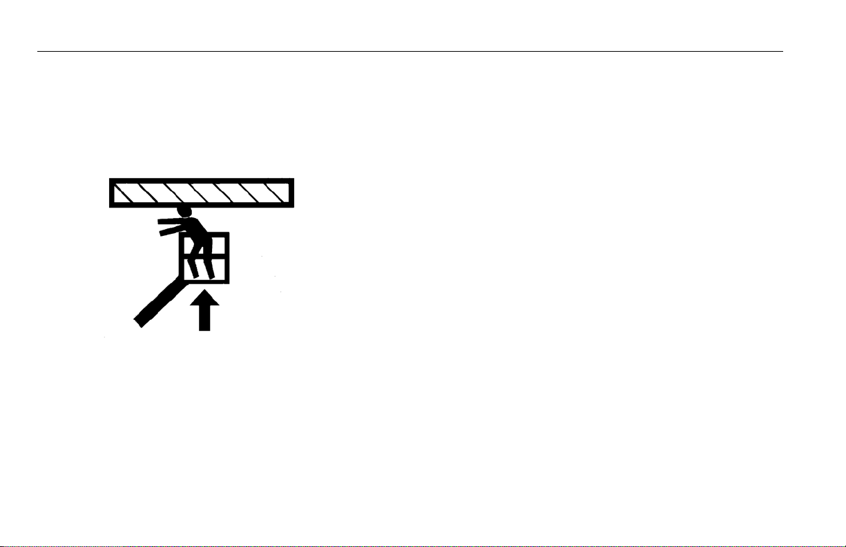
Platform or Boom Caught Overhead . . . . . . . . . . . . . . . 5-2
5.4 EMERGENCY TOWING PROCEDURES. . . . . . . . . . . . . . . . . . 5-2
5.5 MANUAL DESCENT SYSTEM . . . . . . . . . . . . . . . . . . . . . . . . . . 5-2
5.6 MANUAL SWING OVERRIDE . . . . . . . . . . . . . . . . . . . . . . . . . . 5-2
SECTION - 6 - GENERAL SPECIFICATIONS & OPERATOR MAINTENANCE
6.1 INTRODUCTION. . . . . . . . . . . . . . . . . . . . . . . . . . . . . . . . . . . . . . 6-1
6.2 OPERATING SPECIFICATIONS. . . . . . . . . . . . . . . . . . . . . . . . . 6-1
Capacities. . . . . . . . . . . . . . . . . . . . . . . . . . . . . . . . . . . . . . . . . 6-3
Tires . . . . . . . . . . . . . . . . . . . . . . . . . . . . . . . . . . . . . . . . . . . . . . 6-3
Dimensional Data . . . . . . . . . . . . . . . . . . . . . . . . . . . . . . . . . 6-4
Torque Specifications . . . . . . . . . . . . . . . . . . . . . . . . . . . . . 6-4
Hydraulic Oil . . . . . . . . . . . . . . . . . . . . . . . . . . . . . . . . . . . . . . 6-5
Critical Stability Weights. . . . . . . . . . . . . . . . . . . . . . . . . . . 6-6
Serial Number Locations. . . . . . . . . . . . . . . . . . . . . . . . . . . 6-7
6.3 MAINTENANCE AND LUBRICATION . . . . . . . . . . . . . . . . . . 6-10
6.4 BATTERY MAINTENANCE AND CHARGING . . . . . . . . . . . 6-16
Battery Maintenance, Quarterly . . . . . . . . . . . . . . . . . . . 6-16
Optional On Board Generator. . . . . . . . . . . . . . . . . . . . . 6-17
Battery Charging (On Board Charger) . . . . . . . . . . . . . 6-17
6.5 TIRES & WHEELS . . . . . . . . . . . . . . . . . . . . . . . . . . . . . . . . . . . . 6-18
Tire Inflation . . . . . . . . . . . . . . . . . . . . . . . . . . . . . . . . . . . . . 6-18
Tire Damage . . . . . . . . . . . . . . . . . . . . . . . . . . . . . . . . . . . . . 6-18
Tire Replacement. . . . . . . . . . . . . . . . . . . . . . . . . . . . . . . . . 6-18
Wheel Replacement . . . . . . . . . . . . . . . . . . . . . . . . . . . . . . 6-19
ii – JLG Lift – 3121644
Page 9

TABLE OF CONTENTS
SECTION - PARAGRAPH, SUBJECT PAGE SECTION - PARAGRAPH, SUBJECT PAGE
Wheel Installation . . . . . . . . . . . . . . . . . . . . . . . . . . . . . . . 6-19
6.6 SUPPLEMENTAL INFORMATION . . . . . . . . . . . . . . . . . . . . .6-20
SECTION - 7 - INSPECTION AND REPAIR LOG
LIST OF FIGURES
2-1. Basic Nomenclature. . . . . . . . . . . . . . . . . . . . . . . . . . . . . . . . . . 2-7
2-2. Daily Walk-Around Inspection - Sheet 1 of 3 . . . . . . . . . . 2-8
2-3. Daily Walk-Around Inspection - Sheet 2 of 3 . . . . . . . . . . 2-9
2-4. Daily Walk-Around Inspection - Sheet 3 of 3 . . . . . . . . .2-10
3-1. Ground Control Station . . . . . . . . . . . . . . . . . . . . . . . . . . . . . . 3-3
3-2. Platform Control Console . . . . . . . . . . . . . . . . . . . . . . . . . . . . 3-7
3-3. Platform Control Indicator Panel w/Drive Orientation 3-13
4-1. Position of Least Forward Stability . . . . . . . . . . . . . . . . . . . . 4-3
4-2. Position of Least Backward Stability . . . . . . . . . . . . . . . . . . 4-4
4-3. Grade and Side Slopes . . . . . . . . . . . . . . . . . . . . . . . . . . . . . . . 4-7
4-4. Lifting Chart . . . . . . . . . . . . . . . . . . . . . . . . . . . . . . . . . . . . . . . . 4-15
4-5. Decal Installation - Sheet 1 of 3 . . . . . . . . . . . . . . . . . . . . . .4-16
4-6. Decal Installation - Sheet 2 of 3 . . . . . . . . . . . . . . . . . . . . . .4-17
4-7. Decal Installation - Sheet 3 of 3 . . . . . . . . . . . . . . . . . . . . . .4-18
6-1. Serial Number Locations . . . . . . . . . . . . . . . . . . . . . . . . . . . . . 6-7
6-2. E400 Maintenance & Lubrication Diagram . . . . . . . . . . . . 6-8
6-3. M400 Maintenance & Lubrication Diagram. . . . . . . . . . . . 6-9
LIST OF TABLES
1-1 Minimum Approach Distances (M.A.D.) . . . . . . . . . . . . . . . 1-6
1-2 Beaufort Scale (For Reference Only). . . . . . . . . . . . . . . . . . . 1-9
2-1 Inspection and Maintenance Table . . . . . . . . . . . . . . . . . . . 2-3
3-1 Simultaneous Functions. . . . . . . . . . . . . . . . . . . . . . . . . . . . .3-11
4-1 E400A/E400AJP Decal Legend . . . . . . . . . . . . . . . . . . . . . . .4-19
4-2 M400AJP Decal Legend . . . . . . . . . . . . . . . . . . . . . . . . . . . . . 4-25
6-1 Operating Specifications . . . . . . . . . . . . . . . . . . . . . . . . . . . . . 6-1
6-2 Capacities . . . . . . . . . . . . . . . . . . . . . . . . . . . . . . . . . . . . . . . . . . . 6-3
6-3 Tire Specifications. . . . . . . . . . . . . . . . . . . . . . . . . . . . . . . . . . . . 6-3
6-4 Dimensional Data . . . . . . . . . . . . . . . . . . . . . . . . . . . . . . . . . . . . 6-4
6-5 Torque Requirements . . . . . . . . . . . . . . . . . . . . . . . . . . . . . . . . 6-4
6-6 Hydraulic Oil . . . . . . . . . . . . . . . . . . . . . . . . . . . . . . . . . . . . . . . . . 6-5
6-7 Mobil DTE 11M Specs . . . . . . . . . . . . . . . . . . . . . . . . . . . . . . . . 6-5
6-8 Mobil EAL H Series Specs . . . . . . . . . . . . . . . . . . . . . . . . . . . . . 6-6
6-9 Critical Stability Weights . . . . . . . . . . . . . . . . . . . . . . . . . . . . . 6-6
6-10 Lubrication Specifications. . . . . . . . . . . . . . . . . . . . . . . . . . . 6-10
6-11 Wheel Torque Chart. . . . . . . . . . . . . . . . . . . . . . . . . . . . . . . . . 6-20
7-1 Inspection and Repair Log. . . . . . . . . . . . . . . . . . . . . . . . . . . . 7-1
3121644 – JLG Lift – iii
Page 10

TABLE OF CONTENTS
SECTION - PARAGRAPH, SUBJECT PAGE SECTION - PARAGRAPH, SUBJECT PAGE
This page intentionally left blank.
iv – JLG Lift – 3121644
Page 11

1.1 GENERAL
SECTION 1 - SAFETY PRECAUTIONS
SECTION 1. SAFETY PRECAUTIONS
This section outlines the necessary precautions for proper and
safe machine usage and maintenance. It is mandatory that a daily
routine is established based on the content of this manual to promote proper machine usage. A maintenance program, using the
information provided in this manual and the Service and Maintenance Manual, must also be established by a qualified person and
must be followed to ensure that the machine is safe to operate.
The owner/user/operator/lessor/lessee of the machine must not
accept operating responsibility until this manual has been read,
training is accomplished, and operation of the machine has been
completed under the supervision of an experienced and qualified operator.
This section contains the responsibilities of the owner, user, operator, lessor, and lessee concerning safety, training, inspection,
maintenance, application, and operation. If there are any questions with regard to safety, training, inspection, maintenance,
application, and operation, please contact JLG Industries, Inc.
(“JLG”).
FAILURE TO COMPLY WITH THE SAFETY PRECAUTIONS LISTED IN THIS MANUAL
COULD RESULT IN MACHINE DAMAGE, PROPERTY DAMAGE, PERSONAL INJURY OR
DEATH.
1.2 PRE-OPERATION
Operator Training and Knowledge
• The Operation and Safety Manual must be read and understood in its entirety before operating the machine. For clarification, questions, or additional information regarding any
portions of this manual, contact JLG Industries, Inc.
3121644 – JLG Lift – 1-1
Page 12

SECTION 1 - SAFETY PRECAUTIONS
• An operator must not accept operating responsibilities until
adequate training has been given by competent and authorized persons.
• Allow only those authorized and qualified personnel to operate the machine who have demonstrated that they understand the safe and proper operation and maintenance of the
unit.
• Read, understand, and obey all DANGERS, WARNINGS, CAUTIONS, and operating instructions on the machine and in this
manual.
• Ensure that the machine is to be used in a manner which is
within the scope of its intended application as determined by
JLG.
• All operating personnel must be familiar with the emergency
controls and emergency operation of the machine as specified
in this manual.
• Read, understand, and obey all applicable employer, local, and
governmental regulations as they pertain to your utilization
and application of the machine.
Workplace Inspection
• Precautions to avoid all hazards in the work area must be
taken by the user before and during operation of the machine.
• Do not operate or raise the platform from a position on trucks,
trailers, railway cars, floating vessels, scaffolds or other equipment unless the application is approved in writing by JLG.
• Before operation, check work area for overhead hazards such
as electric lines, bridge cranes, and other potential overhead
obstructions.
• Check operating surfaces for holes, bumps, drop-offs, obstructions, debris, concealed holes, and other potential hazards.
• Check the work area for hazardous locations. Do not operate
the machine in hazardous environments unless approved for
that purpose by JLG.
• Ensure that the ground conditions are adequate to support
the maximum tire load indicated on the tire load decals
located on the chassis adjacent to each wheel. Do not travel
on unsupported surfaces.
1-2 – JLG Lift – 3121644
Page 13

SECTION 1 - SAFETY PRECAUTIONS
Machine Inspection
• Do not operate this machine until the inspections and functional checks as specified in Section 2 of this manual have
been performed.
• Do not operate this machine until it has been serviced and
maintained according to the maintenance and inspection
requirements as specified in the machine’s Service and Maintenance Manual.
• Ensure all safety devices are operating properly. Modification
of these devices is a safety violation.
MODIFICATION OR ALTERATION OF AN AERIAL WORK PLATFORM SHALL BE MADE
ONLY WITH PRIOR WRITTEN PERMISSION FROM THE MANUFACTURER.
• Do not operate any machine on which the safety or instruction
placards or decals are missing or illegible.
• Check the machine for modifications to original components.
Ensure that any modifications have been approved by JLG.
• Avoid accumulation of debris on platform floor. Keep mud, oil,
grease, and other slippery substances from footwear and platform floor.
1.3 OPERATION
General
• Machine operation requires your full attention. Bring the
machine to a full stop before using any device, i.e. cell phones,
two-way radios, etc. that will distract your attention from
safely operating the machine.
• Do not use the machine for any purpose other than positioning personnel, their tools, and equipment.
• Before operation, the user must be familiar with the machine
capabilities and operating characteristics of all functions.
• Never operate a malfunctioning machine. If a malfunction
occurs, shut down the machine. Remove the unit from service
and notify the proper authorities.
• Do not remove, modify, or disable any safety devices.
• Never slam a control switch or lever through neutral to an
opposite direction. Always return switch to neutral and stop
before moving the switch to the next function. Operate controls with slow and even pressure.
• Do not allow personnel to tamper with or operate the
machine from the ground with personnel in the platform,
except in an emergency.
3121644 – JLG Lift – 1-3
Page 14
SECTION 1 - SAFETY PRECAUTIONS
• Do not carry materials directly on platform railing unless
approved by JLG.
• When two or more persons are in the platform, the operator
shall be responsible for all machine operations.
• Always ensure that power tools are properly stowed and never
left hanging by their cord from the platform work area.
• When driving, always position boom over rear axle in line with
the direction of travel. Remember, if boom is over the front
axle, steer and drive functions will be reversed.
• Do not assist a stuck or disabled machine by pushing or pulling except by pulling at the chassis tie-down lugs.
• Fully lower platform and shut off all power before leaving
machine.
• Remove all rings, watches, and jewelry when operating
machine. Do not wear loose fitting clothing or long hair unrestrained which may become caught or entangled in equipment.
• Persons under the influence of drugs or alcohol or who are
subject to seizures, dizziness or loss of physical control must
not operate this machine.
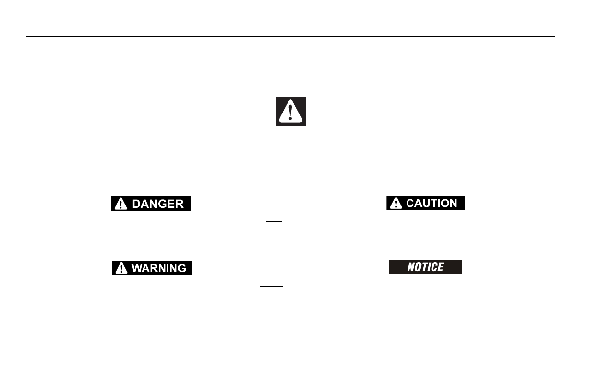
Trip and Fall Hazards
• During operation, occupants in the platform must wear a full
body harness with a lanyard attached to an authorized lanyard
anchorage point. Attach only one (1) lanyard per lanyard
anchorage point..
• Enter and exit only through gate area. Use extreme caution
when entering or leaving platform. Ensure that the platform
assembly is fully lowered. Face the machine when entering or
leaving the platform. Always maintain “three point contact”
with the machine, using two hands and one foot or two feet
and one hand at all times during entry and exit.
1-4 – JLG Lift – 3121644
Page 15
SECTION 1 - SAFETY PRECAUTIONS
• Before operating the machine, make sure all gates are closed
and fastened in their proper position.
• Keep both feet firmly positioned on the platform floor at all
times. Never position ladders, boxes, steps, planks, or similar
items on unit to provide additional reach for any purpose.
• Keep oil, mud, and slippery substances cleaned from footwear
and the platform floor.
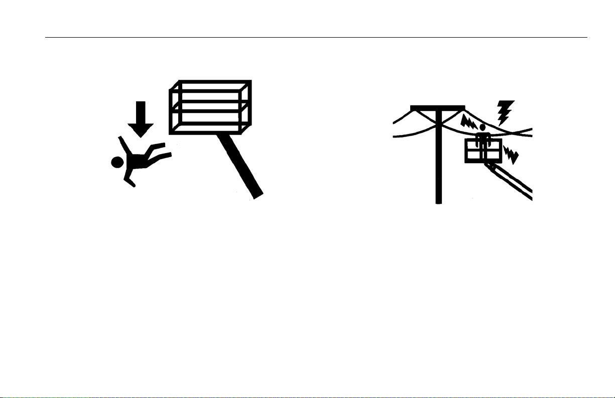
Electrocution Hazards
• This machine is not insulated and does not provide protection
from contact or proximity to electrical current.
3121644 – JLG Lift – 1-5
Page 16
SECTION 1 - SAFETY PRECAUTIONS
Table 1-1. Minimum Approach Distances (M.A.D.)
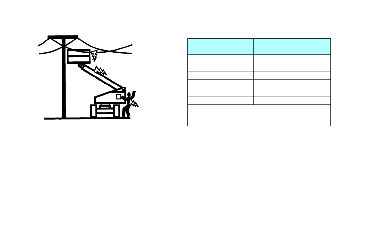
• Maintain distance from electrical lines, apparatus, or any energized (exposed or insulated) parts according to the Minimum
Approach Distance (MAD) as shown in Table 1-1.
• Allow for machine movement and electrical line swaying.
Voltage Range
(Phase to Phase)
0 to 50 KV 10 (3)
Over 50KV to 200 KV 15 (5)
Over 200 KV to 350 KV 20 (6)
Over 350 KV to 500 KV 25 (8)
Over 500 KV to 750 KV 35 (11)
Over 750 KV to 1000 KV 45 (14)
NOTE: This requirement shall apply except where
employer, local or governmental regulations are
more stringent.
• Maintain a clearance of at least 10 ft. (3m) between any part of
the machine and its occupants, their tools, and their equipment from any electrical line or apparatus carrying up to
50,000 volts. One foot additional clearance is required for
every additional 30,000 volts or less.
MINIMUM APPROACH DISTANCE
in Feet (Meters)
1-6 – JLG Lift – 3121644
Page 17
SECTION 1 - SAFETY PRECAUTIONS
• The minimum approach distance may be reduced if insulating
barriers are installed to prevent contact, and the barriers are
rated for the voltage of the line being guarded. These barriers
shall not be part of (or attached to) the machine. The minimum approach distance shall be reduced to a distance within
the designed working dimensions of the insulating barrier.
This determination shall be made by a qualified person in
accordance with the employer, local, or governmental requirements for work practices near energized equipment
DO NOT MANEUVER MACHINE OR PERSONNEL INSIDE PROHIBITED ZONE (MAD).
ASSUME ALL ELECTRICAL PARTS AND WIRING ARE ENERGIZED UNLESS KNOWN OTHERWISE.
Tipping Hazards
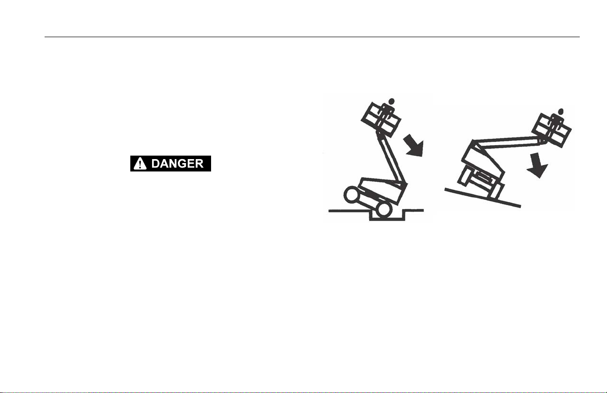
• The user must be familiar with the surface before driving. Do
not exceed the allowable sideslope and grade while driving.
• Do not elevate platform or drive with platform elevated while
on or near a sloping, uneven, or soft surface. Ensure machine is
positioned on a firm, level and smooth surface before elevating platform or driving with the platform in the elevated position.
• Before driving on floors, bridges, trucks, and other surfaces,
check allowable capacity of the surfaces.
3121644 – JLG Lift – 1-7
Page 18

SECTION 1 - SAFETY PRECAUTIONS
• Never exceed the maximum work load as specified on the
platform. Keep all loads within the confines of the platform,
unless authorized by JLG.
• Keep the chassis of the machine a minimum of 2 ft. (0.6m)
from holes, bumps, drop-offs, obstructions, debris, concealed
holes, and other potential hazards at the ground level.
• Do not push or pull any object with the boom.
• Never attempt to use the machine as a crane. Do not tie-off
machine to any adjacent structure. Never attach wire, cable, or
any similar items to platform.
• Do not operate the machine when wind conditions exceed 28
mph (12.5 m/s). Refer to Table 1-2, Beaufort Scale (For Reference Only).
• Do not increase the surface area of the platform or the load.
Increase of the area exposed to the wind will decrease stability.
• Do not increase the platform size with unauthorized deck
extensions or attachments.
• If boom assembly or platform is in a position that one or more
wheels are off the ground, all persons must be removed before
attempting to stabilize the machine. Use cranes, forklift trucks,
or other appropriate equipment to stabilize machine.
1-8 – JLG Lift – 3121644
Page 19
DO NOT OPERATE THE MACHINE WHEN WIND CONDITIONS EXCEED 28 MPH (12.5 M/
S).
Table 1-2. Beaufort Scale (For Reference Only)
SECTION 1 - SAFETY PRECAUTIONS
Beaufort
Number
0 0 0-0.2 Calm Calm. Smoke rises vertically
1 1-3 0.3-1.5 Light air Wind motion visible in smoke
2 4-7 1.6-3.3 Light breeze Wind felt on exposed skin. Leaves rustle
3 8-12 3.4-5.4 Gentle breeze Leaves and smaller twigs in constant motion
4 13-18 5.5-7.9 Moderate breeze Dust and loose paper raised. Small branches begin to move.
5 19-24 8.0-10.7 Fresh breeze Smaller trees sway.
6 25-31 10.8-13.8 Strong breeze Large branches in motion. Flags waving near horizontal. Umbrella use
7 32-38 13.9-17.1 Near Gale/Moderate Gale Whole trees in motion. Effort needed to walk against the wind.
8 39-46 17.2-20.7 Fresh Gale Twigs broken fro m trees. Cars veer on road.
9 47-54 20.8-24.4 Strong Gale Light structure damage.
Wind Speed
mph m/s
Description Land Conditions
becomes difficult.
3121644 – JLG Lift – 1-9
Page 20
SECTION 1 - SAFETY PRECAUTIONS
Crushing and Collision Hazards
• Approved head gear must be worn by all operating and
ground personnel.
• Check work area for clearances overhead, on sides, and bottom of platform when lifting or lowering platform, and driving.
• During operation, keep all body parts inside platform railing.
• Use the boom functions, not the drive function, to position the
platform close to obstacles.
• Always post a lookout when driving in areas where vision is
obstructed.
• Keep non-operating personnel at least 6 ft. (1.8m) away from
machine during all driving and swing operations.
• Under all travel conditions, the operator must limit travel
speed according to conditions of ground surface, congestion,
visibility, slope, location of personnel, and other factors which
may cause collision or injury to personnel.
• Be aware of stopping distances in all drive speeds. When driving in high speed, switch to low speed before stopping. Travel
grades in low speed only.
• Do not use high speed drive in restricted or close quarters or
when driving in reverse.
• Exercise extreme caution at all times to prevent obstacles from
striking or interfering with operating controls and persons in
the platform.
• Be sure that operators of other overhead and floor level
machines are aware of the aerial work platform’s presence. Disconnect power to overhead cranes.
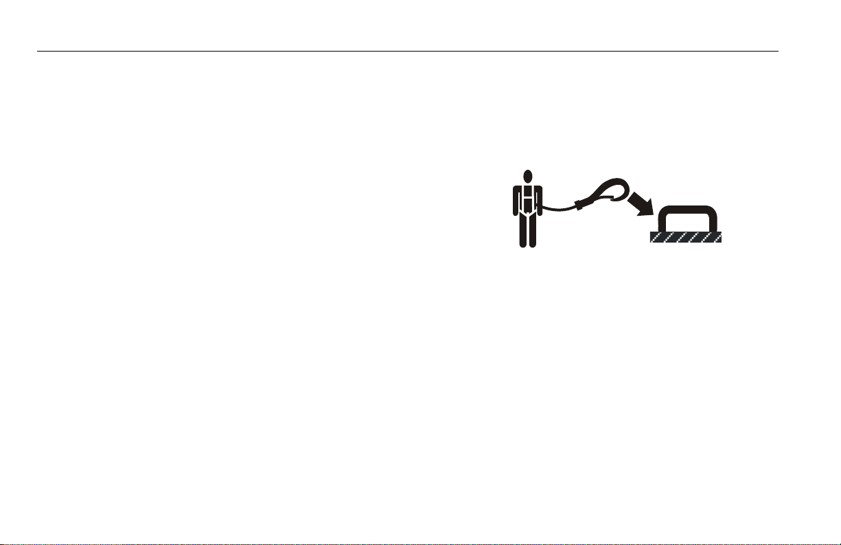
• Warn personnel not to work, stand, or walk under a raised
boom or platform. Position barricades on floor if necessary.
1-10 – JLG Lift – 3121644
Page 21

SECTION 1 - SAFETY PRECAUTIONS
1.4 TOWING, LIFTING, AND HAULING
• Never allow personnel in platform while towing, lifting, or
hauling.
• This machine should not be towed, except in the event of
emergency, malfunction, power failure, or loading/unloading.
Refer to the Emergency Procedures section of this manual for
emergency towing procedures.
• Ensure boom is in the stowed position and the turntable
locked prior to towing, lifting or hauling. The platform must be
completely empty of tools.
• When lifting machine, lift only at designated areas of the
machine. Lift the unit with equipment of adequate capacity.
• Refer to the Machine Operation section of this manual for lifting information.
1.5 MAINTENANCE
This sub-section contains general safety precautions which must
be observed during maintenance of this machine. Additional precautions to be observed during machine maintenance are
inserted at the appropriate points in this manual and in the Service and Maintenance Manual. It is of utmost importance that
maintenance personnel pay strict attention to these precautions
to avoid possible injury to personnel or damage to the machine
or property. A maintenance program must be established by a
qualified person and must be followed to ensure that the
machine is safe.
Maintenance Hazards
• Shut off power to all controls and ensure that all moving parts
are secured from inadvertent motion prior to performing any
adjustments or repairs.
• Never work under an elevated platform until it has been fully
lowered to the full down position, if possible, or otherwise
supported and restrained from movement with appropriate
safety props, blocking, or overhead supports.
• DO NOT attempt to repair or tighten any hydraulic hoses or fittings while the machine is powered on or when the hydraulic
system is under pressure.
• Always relieve hydraulic pressure from all hydraulic circuits
before loosening or removing hydraulic components.
3121644 – JLG Lift – 1-11
Page 22
SECTION 1 - SAFETY PRECAUTIONS
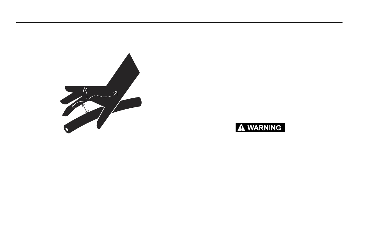
• DO NOT use your hand to check for leaks. Use a piece of cardboard or paper to search for leaks. Wear gloves to help protect
hands from spraying fluid.
• Ensure replacement parts or components are identical or
equivalent to original parts or components.
• Never attempt to move heavy parts without the aid of a
mechanical device. Do not allow heavy objects to rest in an
unstable position. Ensure adequate support is provided when
raising components of the machine.
• Do not use machine as a ground for welding.
• When performing welding or metal cutting operations, precautions must be taken to protect the chassis from direct
exposure to weld and metal cutting spatter.
• Do not refuel the machine with the engine running.
• Use only approved non-flammable cleaning solvents.
• Do not replace items critical to stability, such as batteries or
solid tires, with items of different weight or specification. Do
not modify unit in any way to affect stability.
• Refer to the Service and Maintenance Manual for the weights
of critical stability items.
MODIFICATION OR ALTERATION OF AN AERIAL WORK PLATFORM SHALL BE MADE
ONLY WITH PRIOR WRITTEN PERMISSION FROM THE MANUFACTURER.
1-12 – JLG Lift – 3121644
Page 23

Battery Hazards
SECTION 1 - SAFETY PRECAUTIONS
• Always disconnect batteries when servicing electrical components or when performing welding on the machine.
• Do not allow smoking, open flame, or sparks near battery during charging or servicing.
• Do not contact tools or other metal objects across the battery
terminals.
• Always wear hand, eye, and face protection when servicing
batteries. Ensure that battery acid does not come in contact
with skin or clothing.
BATTERY FLUID IS HIGHLY CORROSIVE. AVOID CONTACT WITH SKIN AND
CLOTHING AT ALL TIMES. IMMEDIATELY RINSE ANY CONTACTED AREA WITH
CLEAN WATER AND SEEK MEDICAL ATTENTION.
• Charge batteries only in a well ventilated area.
• Avoid overfilling the battery fluid level. Add distilled water to
batteries only after the batteries are fully charged.
3121644 – JLG Lift – 1-13
Page 24

SECTION 1 - SAFETY PRECAUTIONS
NOTES:
1-14 – JLG Lift – 3121644
Page 25

SECTION 2 - USER RESPONSIBILITIES, MACHINE PREPARATION, AND INSPECTION
SECTION 2. USER RESPONSIBILITIES, MACHINE PREPARATION, AND INSPECTION
2.1 PERSONNEL TRAINING
The aerial platform is a personnel handling device; so it is necessary that it be operated and maintained only by trained personnel.
Persons under the influence of drugs or alcohol or who are subject to seizures, dizziness or loss of physical control must not
operate this machine.
Operator Training
Operator training must cover:
1. Use and limitations of the controls in the platform and at the
ground, emergency controls and safety systems.
2. Control labels, instructions, and warnings on the machine.
3. Rules of the employer and government regulations.
4. Use of approved fall protection device.
5. Enough knowledge of the mechanical operation of the
machine to recognize a malfunction or potential malfunction.
6. The safest means to operate the machine where overhead
obstructions, other moving equipment, and obstacles,
depressions, holes, drop-offs.
7. Means to avoid the hazards of unprotected electrical conductors.
8. Specific job requirements or machine application.
Training Supervision
Training must be done under the supervision of a qualified person in an open area free of obstructions until the trainee has
developed the ability to safely control and operate the machine.
Operator Responsibility
The operator must be instructed that he/she has the responsibility and authority to shut down the machine in case of a malfunction or other unsafe condition of either the machine or the job
site.
3121644 – JLG Lift – 2-1
Page 26

SECTION 2 - USER RESPONSIBILITIES, MACHINE PREPARATION, AND INSPECTION
2.2 PREPARATION, INSPECTION, AND MAINTENANCE
The following table covers the periodic machine inspections and
maintenance recommended by JLG Industries, Inc. Consult local
regulations for further requirements for aerial work platforms.
The frequency of inspections and maintenance must be
increased as necessary when the machine is used in a harsh or
hostile environment, if the machine is used with increased frequency, or if the machine is used in a severe manner.
JLG INDUSTRIES, INC. RECOGNIZES A FACTORY-QUALIFIED SERVICE TECHNICIAN AS A
PERSON WHO HAS SUCCESSFULLY COMPLETED THE JLG SERVICE TRAINING SCHOOL
FOR THE SPECIFIC JLG PRODUCT MODEL.
2-2 – JLG Lift – 3121644
Page 27

SECTION 2 - USER RESPONSIBILITIES, MACHINE PREPARATION, AND INSPECTION
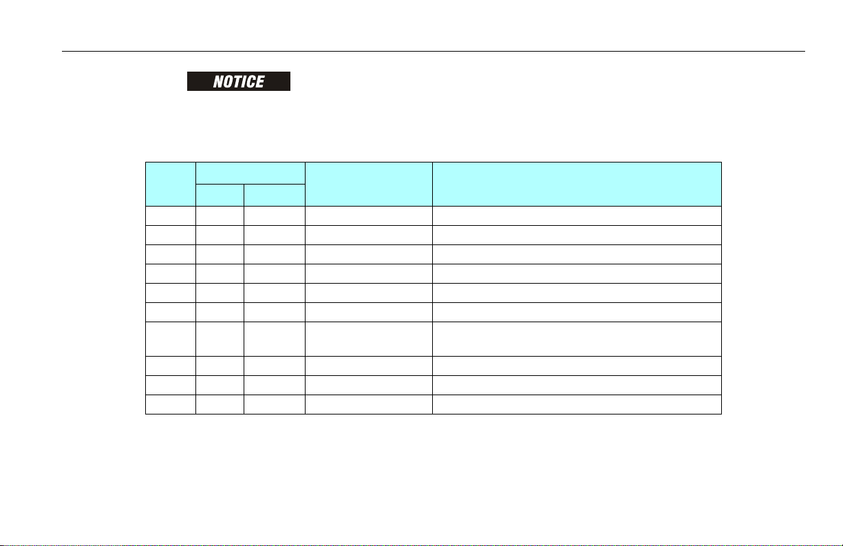
Table 2-1.Inspection and Maintenance Table
Type Freq uenc y
Pre-Start Inspection Before using each day; or
whenever there’s an Operator change.
Pre-Delivery Inspect ion (See Note) Before each sale, lease, or rental delivery. Owner, Dealer, or User Qualified JLG Mechanic Service and Maintenance Manual
Frequent Inspection In service for 3 months or 1 50 hours, whichever comes first;
o r
Out of service for a period of more than 3 months;
o r
Purchase d used.
Annual Machine Inspection Annually, no later than 13 months from the date of prior
inspection.
Preventative Maintenance At intervals as specified in the Service and Maintenance
Manual.
NOTE: Inspection forms are available from JLG. Use the Service and Maintenance Manual to perform inspections.
Primary
Responsibility
User or Operator User or Operator Operator and Safety Manual
Owner, Dealer, or User Q ualified JLG Mechanic Service and Maintenance Manual
Owner, Dealer, or User Factory Qualified
Owner, Dealer, or User Q ualified JLG Mechanic Service and Maintenance Manual
Service
Qualification
Service Technician
(Recommended)
Reference
and applicable JLG inspection form
and applicable JLG inspection form
Service and Maintenance Manual
and applicable JLG inspection form
3121644 – JLG Lift – 2-3
Page 28
SECTION 2 - USER RESPONSIBILITIES, MACHINE PREPARATION, AND INSPECTION
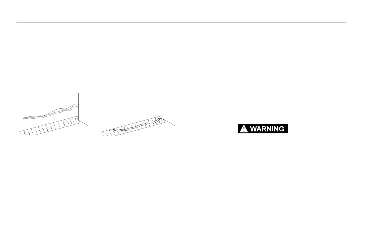
Parent Metal Crack Weld Crack
Pre-Start Inspection
The Pre-Start Inspection should include each of the following:
1. Cleanliness – Check all surfaces for leakage (oil, fuel, or battery fluid) or foreign objects. Report any leakage to the
proper maintenance personnel.
2. Structure - Inspect the machine structure for dents, damage, weld or parent metal cracks or other discrepancies.
3. Decals and Placards – Check all for cleanliness and legibility. Make sure none of the decals and placards are missing.
Make sure all illegible decals and placards are cleaned or
replaced.
4. Operators and Safety Manuals – Make sure a copy of the
Operator and Safety Manual, AEM Safety Manual (Domestic
only), and ANSI Manual of Responsibilities (Domestic only) is
enclosed in the weather resistant storage container.
5. “Walk-Around” Inspection – Refer to Figure 2-2. thru Figure 2-4.
6. Battery – Charge as required.
7. Fuel (Combustion Engine Powered Machines) – Add the
proper fuel as necessary.
8. Hydraulic Oil – Check the hydraulic oil level. Ensure hydraulic oil is added as required.
9. Function Check – Once the “Walk-Around” Inspection is
complete, perform a functional check of all systems in an
area free of overhead and ground level obstructions. Refer to
Section 4 for more specific instructions.
IF THE MACHINE DOES NOT OPERATE PROPERLY, TURN OFF THE MACHINE IMMEDIATELY! REPORT THE PROBLEM TO THE PROPER MAINTENANCE PERSONNEL. DO NOT
OPERATE THE MACHINE UNTIL IT IS DECLARED SAFE FOR OPERATION.
2-4 – JLG Lift – 3121644
Page 29

SECTION 2 - USER RESPONSIBILITIES, MACHINE PREPARATION, AND INSPECTION
Function Check
A functional check of all systems should be performed, once the
walk-around inspection is complete, in an area free of overhead
and ground level obstructions. First, using the ground controls,
check all functions controlled by the ground controls. Next, using
the platform controls, check all functions controlled by the platform controls.
TO AVOID SERIOUS INJURY, DO NOT OPERATE MACHINE IF ANY CONTROL LEVERS OR
TOGGLE SWITCHES CONTROLLING PLATFORM MOVEMENTS DO NOT RETURN TO THE
OFF POSITION WHEN RELEASED.
TO AVOID A COLLISION AND INJURY IF PLATFORM DOES NOT STOP WHEN A CONTROL
SWITCH OR LEVER IS RELEASED, REMOVE FOOT FROM FOOTSWITCH OR USE EMERGENCY STOP TO STOP MACHINE.
1. Check boom limit switches. Raise and lower the Lower
Boom. Check for smooth operation.
NOTE: Perform checks from ground controls first, then from platform
controls.
2. Raise, extend, retract, and lower the Upper Boom. Check for
smooth operation.
3. If tower boom does not rest on stop with machine in the
stowed position, this indicates upright is out of plumb.
4. Telescope boom IN and OUT several cycles at various
degrees of elevation lengths. Check for smooth telescope
operation.
5. Swing turntable to LEFT and RIGHT a minimum of 45
degrees. Check for smooth motion.
6. Check the chassis tilt indicator located on the platform control console by driving, with the machine in stowed position,
up a suitable ramp of at least 6° slope. Check the tilt alarm,
with the machine on the ramp, raise the upper boom until it
is parallel with the chassis. DO NOT RAISE ABOVE THE PARALLEL POSITION. If the light does not illuminate, return the
machine to a level surface, shut down the machine, and contact a qualified technician before resuming operation.
For units equipped with optional tilt cutout, verify that the
drive function is cutout when the boom is elevated and tilt
alarm is activated.
3121644 – JLG Lift – 2-5
Page 30

SECTION 2 - USER RESPONSIBILITIES, MACHINE PREPARATION, AND INSPECTION
With footswitch depressed, operate LIFT and hold control.
Remove foot from footswitch, motion should stop. If it does
DO NOT DRIVE ON GRADES WHICH EXCEED THE RATED GRADEABILITY OF THE
MACHINE AS INDICATED ON THE SERIAL NUMBER PLATE. DO NOT DRIVE ON SIDESLOPES WHICH EXCEED 5 DEGREES.
7. Check that platform self-leveling system functions properly
during raising and lowering of boom.
8. Check rotator for smooth operation and assure platform will
rotate 75 degrees in both directions from centerline of
boom.
9. Drive forward and reverse; check for proper operation.
10. Steer left and right; check for proper operation.
11. Footswitch.
FOOTSWITCH MUST BE ADJUSTED SO THAT FUNCTIONS WILL OPERATE WHEN PEDAL
IS APPROXIMATELY AT ITS CENTER OF TRAVEL. IF SWITCH OPERATES WITHIN LAST 1/
4" (6 MM) OF TRAVEL, TOP OR BOTTOM, IT SHOULD BE ADJUSTED.
not, shut down machine and contact a qualified service technician.
12. Place the GROUND/PLATFORM SELECT switch to GROUND.
Platform controls should not operate.
13. Place GROUND/PLATFORM SELECT switch to OFF. Platform/
Ground controls should not operate.
FOOTSWITCH MUST BE DEPRESSED PRIOR TO ACTIVATING ANY FUNCTION CONTROL,
OTHERWISE THE FUNCTION WILL NOT WORK.
2-6 – JLG Lift – 3121644
Page 31

SECTION 2 - USER RESPONSIBILITIES, MACHINE PREPARATION, AND INSPECTION
Figure 2-1. Basic Nomenclature
1. P la t fo r m C o nt ro l Co n so l e
2. P la t fo r m
3. U pp e r Bo o m
4. Te le s co p e C yl i nd e r ( i ns i de )
5. M as t er Cy l in d er
6. U pp e r Up r ig h t
7. U pp e r Li f t C yl i nd e r
8. M id L i ft Cy l in d er
9. L ow er B o om
10. Turntable
11. Frame
12. Steer Wheels
13. Drive Wheels
14. Battery Box
15. Lower Lift Cylinder
16. Lower Link
17. Lower Upright
18. Upper Link
19. Mid Boom
20. Slave Cylinder
21. Footswitch
3121644 – JLG Lift – 2-7
Page 32

SECTION 2 - USER RESPONSIBILITIES, MACHINE PREPARATION, AND INSPECTION
Figure 2-2. Daily Walk-Around Inspection - Sheet 1 of 3
2-8 – JLG Lift – 3121644
Page 33

SECTION 2 - USER RESPONSIBILITIES, MACHINE PREPARATION, AND INSPECTION
General
Begin the “Walk-Around Inspection” at Item 1, as noted on the
diagram. Continue to the right (counterclockwise viewed from
top) checking each item in sequence for the conditions listed in
the “Walk-Around Inspection Checklist”.
TO AVOID POSSIBLE INJURY BE SURE MACHINE POWER IS OFF DURING "WALKAROUND INSPECTION".
DO NOT OVERLOOK VISUAL INSPECTION OF CHASSIS UNDERSIDE. CHECKING THIS
AREA MAY RESULT IN DISCOVERY OF CONDITIONS WHICH COULD CAUSE EXTENSIVE
MACHINE DAMAGE.
NOTE: On each item, make sure there are no loose or missing parts,
that they are securely fastened and that no visible damage
exists in addition to any other criteria mentioned.
1. Platform and Gate Assembly - Platform mounting pins
secure. Footswitch in good working order; not modified,
disabled or blocked; Bar slides freely.
2. Platform & Ground Control Console - Switches and levers
return to neutral and are properly secured, decals/placards
secure and legible, control marking legible.
3. Rotator - See Note.
4. Jib - See Note.
5. Jib Rotator - See Note.
6. Boom Sections - See Note.
7. All Hydraulic Cylinders - No visible damage; pivot pins and
hydraulic hoses undamaged, not leaking.
8. Limit Switches - See Note.
Figure 2-3. Daily Walk-Around Inspection - Sheet 2 of 3
3121644 – JLG Lift – 2-9
Page 34

SECTION 2 - USER RESPONSIBILITIES, MACHINE PREPARATION, AND INSPECTION
9. Drive Axle and Motor - See Note.
10. Wheel/Tire Assembly - No loose or missing lug nuts.
Inspect for worn tread, cuts, tears or other discrepancies.
Inspect wheels for damage and corrosion.
11. Swing Motor and Worm Gear - See Note.
12. Hydraulic Pump and Reservoir - Properly secured; no visi-
ble damage or hydraulic leaks. Recommended hydraulic
fluid level on dipstick (system shut down, boom in stowed
position). Breather cap/dipstick secure and working.
13. Turntable Bearing - No loose or missing hardware; no visible damage; evidence of proper lubrication. No loose bolts
or looseness between bearing and structure.
14. Battery Compartment Right Side - Batteries have proper
electrolyte level; cables tight; no visible damage or corrosion.
15. Cowling and Latches - See Note.
16. Battery Charger - See Note.
17. Brake/Steer Valve - See Note.
18. Boom/Upright - No visible damage; All pins properly
secured. Upright in vertical position. If Upright does not
rest on stop with machine in the stowed position, this indicates upright is out of plumb.
19. Counterweight - See Note.
20. Tie Rod Ends and Steering Spindles - See Note. Tie rod end
stubs locked.
21. Manual Descent Valve - See Note.
22. Control Valve - See Note.
23. Frame - See Note.
24. Platform Pivot Pins - Properly secured.
Figure 2-4. Daily Walk-Around Inspection - Sheet 3 of 3
2-10 – JLG Lift – 3121644
Page 35

SECTION 3 - MACHINE CONTROLS AND INDICATORS
SECTION 3. MACHINE CONTROLS AND INDICATORS
3.1 GENERAL
THE MANUFACTURER HAS NO DIRECT CONTROL OVER MACHINE APPLICATION AND
OPERATION. THE USER AND OPERATOR ARE RESPONSIBLE FOR CONFORMING WITH
GOOD SAFETY PRACTICES.
This section provides the necessary information needed to
understand control functions.
3.2 CONTROLS AND INDICATORS
NOTE: This machines is equipped with control panels that use symbols
to indicate control functions. On ANSI machines, refer to decal
located on the control box guard in front of the control box or by
the ground controls for these symbols and the corresponding
functions.
NOTE: The indicator panels use different shaped symbols to alert the
operator to different types of operational situations that could
arise. The meaning of those symbols are explained below.
Indicates a potentially hazardous situation, which if
not corrected, could result in serious injury or death.
This indicator will be red.
Indicates an abnormal operating condition, which if
not corrected, may result in machine interruption or
damage. This indicator will be yellow.
Indicates important information regarding the operating condition, i.e. procedures essential for safe operation. This indicator will be green with the exception of
the capacity indicator which will be green or yellow
depending upon platform position.
3121644 – JLG Lift – 3-1
Page 36

SECTION 3 - MACHINE CONTROLS AND INDICATORS
Ground Control Station
(See Figure 3-1.)
NOTE: When machine is shut down the Platform/Ground Select switch
and Emergency Stop must be positioned to Off.
NOTE: The Function Enable switch must be held down in order to oper-
ate Telescope, Lower Lift, Swing, Main Lift, Jib Lift, Platform Level
Override, and Platform Rotate functions.
1. System Distress Indicator (If Equipped)
The system distress indicator lights to signify an abnormal condition for the generator engine (high oil temperature or low oil
pressure) or, on electric machines, an electrical system fault.
NOTE: The engine will automatically shut down under the following
conditions:
High Oil Temperature
Low Oil Pressure
Engine Overspeed
Overvoltage
2. Platform Overload (If equipped)
Indicates the platform has been overloaded.
3. Generator/Engine Start Button
The generator/engine start push-button
switch allows the generator to be started
manually to top-off the battery charge. The
generator will start automatically when the
batteries reach a low-charge state and the Generator Enable
switch on the platform console is in the on position.
NOTE: The engine will not start if the batteries are fully charged or if the
Generator Enable switch on the platform console is not in the on
position.
4. Battery Indicator and Hourmeter
An hourmeter, installed in the upper portion of the Ground Control Box, registers the
amount of machine operating time. The
hourmeter registers up to 9,999.9 hours and
cannot be reset.
3-2 – JLG Lift – 3121644
Page 37

SECTION 3 - MACHINE CONTROLS AND INDICATORS
Figure 3-1. Ground Control Station
1. System Distress Indicator
2. Platform Overload Indicator
3. Engine/Generator Start Button
4. Battery Condition Indicator & Hourmeter
5. Telescope
6. Swing
7. Function Enable
8. Circuit Breakers
9. Emergency Stop
10. Platform/Ground Select
11. Lower/Mid Lift
12. Upper Boom Lift
13. Jib
14. Platform Leveling
15. Rotate
3121644 – JLG Lift – 3-3
Page 38

SECTION 3 - MACHINE CONTROLS AND INDICATORS
5. Telescope
Provides for extension and retraction of Upper
Boom when positioned to in or out.
6. Swing
The Swing control switch provides 360
degrees non-continuous turntable rotation.
To activate Swing, position switch to Left or
Right.
7. Function Enable
The enable switch must be held "Down" to
enable all boom controls when the engine is
running.
8. Circuit Breakers
The circuit breakers open (pop out) to indicate a short or
overload somewhere on the machine.
9. Power/Emergency Stop Switch
A two-position red mushroom shaped switch
furnishes power to Platform/Ground Select
switch when pulled out (on). When pushed in
(off), power is shut off to the Platform/Ground Select switch.
10. Platform/Ground Select Switch
A three position, key operated switch
supplies power to the platform control
console when positioned to Platform.
With the switch key in the Ground position, power is shut off to platform and
only ground controls are operable.
NOTE: With Platform/Ground Select switch in the center position,
power is shut off to controls at both operating stations.
3-4 – JLG Lift – 3121644
Page 39

11. Lower/Mid Boom Lift
SECTION 3 - MACHINE CONTROLS AND INDICATORS
Provides for raising and lowering of
Lower Boom when positioned to Up or
Down.
12. Upper Boom Lift
Provides for raising and lowering of Upper
Boom when positioned to Up or Down.
13. Jib (If equipped)
The Jib control switch provides raising and
lowering of the jib when positioned up or
down.
ONLY USE THE PLATFORM LEVELING OVERRIDE FUNCTION FOR SLIGHT LEVELING OF
THE PLATFORM. INCORRECT USE COULD CAUSE THE LOAD/OCCUPANT TO SHIFT OR
FALL. FAILURE TO DO SO COULD RESULT IN DEATH OR SERIOUS INJURY.
14. Platform Leveling Override
A three position switch allows the operator to
adjust the automatic self leveling system. This
switch is used to adjust platform level in situations such as ascending/descending a grade.
15. Rotate
A three position Rotate control switch permits
rotation of the platform when positioned to left
or right.
3121644 – JLG Lift – 3-5
Page 40

SECTION 3 - MACHINE CONTROLS AND INDICATORS
Platform Station
(See Figure 3-3.)
1. Posi-Track Control
Activating the Posi-Track switch allows
the operator to engage positive traction for the time period pre-set in the
controller. Posi-traction occurs by changing the drive motors
from a series to parallel arrangement, causing available
power to be distributed evenly between the two drive
wheels. The control system may also engage the posi-track
function automatically.
ONLY USE THE PLATFORM LEVELING OVERRIDE FUNCTION FOR SLIGHT LEVELING OF
THE PLATFORM. INCORRECT USE COULD CAUSE THE LOAD/OCCUPANT TO SHIFT OR
FALL. FAILURE TO DO SO COULD RESULT IN DEATH OR SERIOUS INJURY.
2. Platform Leveling Override
A three position switch allows the operator to
adjust the automatic self leveling system. This
switch is used to adjust platform level in situations such as ascending/descending a grade.
3. Horn
A push-type Horn switch supplies electrical
power to an audible warning device when pressed.
4. Power/Emergency Stop
A two-position red mushroom shaped switch
furnishes power to Platform Controls when
pulled out (on). When pushed in (off), power is
shut off to the platform functions.
Within about 2 seconds of pulling the switch out, the
machine will perform a diagnostic check of the various electrical circuits, and if everything is OK, the platform alarm will
beep once. During this time the lights on the indicator panel
will also blink once as a bulb check.
3-6 – JLG Lift – 3121644
Page 41

SECTION 3 - MACHINE CONTROLS AND INDICATORS
1. Posi-Track
2. Platform Leveling Override
3. Horn
4. Power/Emergency Stop
5. Generator Enable
6. Drive Orientation Override
7. Drive/Steer
8. Telescope
9. Lights
10. Jib
11. Soft Touch Override
12. Jib Swing
13. Lower Boom Lift
14. Platform Rotate
15. Function Speed
16. Main Lift/Swing
Figure 3-2. Platform Control Console
3121644 – JLG Lift – 3-7
Page 42

SECTION 3 - MACHINE CONTROLS AND INDICATORS
5. Generator Enable Control
The Generator Enable control switch, when in
the off position, allows the operator to prevent
the generator engine from starting when
using the machine indoors. When in the on
position (and the ground Emergency Stop
Switch on [pulled out]), the generator is enabled to automatically start when the batteries need charged.
6. Drive Orientation Override
When the boom is swung over the rear tires
or further in either direction, the Drive Orientation indicator will illuminate when the drive
function is selected. Push and release the
switch, and within 3 seconds move the Drive/Steer control
to activate drive or steer. Before driving, locate the black/
white orientation arrows on both the chassis and the platform controls and match the control direction arrow to the
intended direction of travel.
NOTE: To operate the Drive joystick, pull up on the lock-
ing ring below the handle.
NOTE: The Drive joystick is spring loaded and will auto-
matically return to neutral (off) position when
released.
7. Drive/Steer
The Drive controller provides for
driving either forward or backward when positioned to Forward or Reverse. The controller is
‘ramped’ to allow infinitely variable drive speed between fast
and slow.
Positioning the steer control thumb operated switch Right
or Left enables steering the machine to the right or left
respectively.
NOTE: When lower boom is raised above horizontal, or the upper boom
is raised approximately 16 inches (40.64 cm) above boom rest,
the high drive function will automatically switch to low drive.
This also occurs when Function Speed Control is clicked on creep.
3-8 – JLG Lift – 3121644
Page 43

SECTION 3 - MACHINE CONTROLS AND INDICATORS
11. Soft Touch Override Switch (If equipped)
TO AVOID SERIOUS INJURY, DO NOT OPERATE MACHINE IF ANY CONTROL LEVERS OR
TOGGLE SWITCHES CONTROLLING PLATFORM MOVEMENT DO NOT RETURN TO THE
OFF OR NEUTRAL POSITION WHEN RELEASED.
8. Telescope Control
The TELESCOPE control switch affords extension
and retraction of the main boom when positioned to IN or OUT.
9. Lights (If Equipped)
This switch operates control console panel
lights and head lights if the machine is so
equipped.
10. Jib (If Equipped)
Push forward to lift up, pull back to lift down.
Variable lift speed is using the Function
Speed Control.
This switch enables the functions that
were cut out by the Soft Touch system to
operate again at creep speed, allowing the operator to move
the platform away from the obstacle that caused the shutdown situation.
12. Jib Swing
Push toggle switch right to swing right, push
left to swing left.
13. Lower Boom Lift
Provides for raising and lowering of Lower
and Mid Boom when positioned to UP or
DOWN. Upper lift will not function when
operating lower lift.
3121644 – JLG Lift – 3-9
Page 44

SECTION 3 - MACHINE CONTROLS AND INDICATORS
14. Platform Rotate
The PLATFORM ROTATE control switch allows
the operator to rotate the basket to the left or
right when positioned to the desired direction.
15. Function Speed Control
Adjusts speed of Boom and Swing Functions. Rotate counterclockwise for slower
speed and clockwise for faster speed. To
adjust Drive, Swing, and Main Lift to creep,
turn knob fully counterclockwise until it
clicks.
NOTE: To operate the Main Boom Lift/Swing joystick,
pull up on the locking ring below the handle.
NOTE: The Main Boom Lift/Swing joystick is spring loaded and will
automatically return to neutral (off) position when released.
16. Main Lift/Swing Controller
Provides main lift and swing. Push forward to lift up, pull backward to boom
down. Move right to swing right, move
left to swing left. Moving the joystick
activates switches to provide the functions selected.
NOTE: Lower lift will not function when operating main lift.
3-10 – JLG Lift – 3121644
Page 45

SECTION 3 - MACHINE CONTROLS AND INDICATORS
Table 3-1. Simultaneous Functions
If This Function is Selected: These Functions Will Also Work at the Same Time:
Drive and Steer Swing Lower Lift** Upper Lift** Telescope
Swing
Lower Lift
Upper Lift
Tel e s co p e
Jib
Platform Rotate
Drive and Steer
Drive and Steer
Drive and Steer
Drive and Steer
Drive and Steer
Drive and Steer
Lower Lift** Upper Lift** Telescope
Swing* No Telescope*
Swing No Tel e sc op e
Swing* Lower Lift** Upper Lift**
Swing* Lower Lift** Upper Lift** Telescope
No No No No
Note: Boom functions may be slower when selected with another function than when operated individually, due to sharing of oil.
* These functions may move very slowly (or not at all) if the first function sele cted (Lower Lift or Swing) is being operated at full speed, due to sharing of oil.
** Lower Lift and Upper Lift will not function simultaneously. Upper Lift always prevails.
3121644 – JLG Lift – 3-11
Page 46

SECTION 3 - MACHINE CONTROLS AND INDICATORS
Platform Control Indicator Panel
(See Figure 3-3., Platform Control Indicator Panel w/Drive Orientation)
1. Tilt Alarm Warning Light and Alarm
This illuminator indicates that the chassis is
on a slope. An alarm will also sound when the
chassis is on a slope and the boom is above
horizontal. If lit when boom is raised or
extended, retract and lower to below horizontal then reposition machine so that it is level before continuing operation.
If the boom is above horizontal and the machine is on a
slope, the tilt alarm warning light will illuminate and an
alarm will sound and Creep is automatically activated.
IF TILT WARNING LIGHT IS ILLUMINATED WHEN BOOM IS RAISED OR EXTENDED,
RETRACT AND LOWER TO BELOW HORIZONTAL THEN REPOSITION MACHINE SO THAT
IT IS LEVEL BEFORE EXTENDING BOOM OR RAISING BOOM ABOVE HORIZONTAL.
2. Platform Overload (If equipped)
Indicates the platform has been overloaded.
3-12 – JLG Lift – 3121644
Page 47

SECTION 3 - MACHINE CONTROLS AND INDICATORS
1. Tilt
2. Platform Overload
3. System Distress
4. Posi-Track
5. Enable
6. Low Battery
7. Creep
8. Drive Orientation Override
9. Soft Touch Indicator
Figure 3-3. Platform Control Indicator Panel w/Drive Orientation
3121644 – JLG Lift – 3-13
Page 48

SECTION 3 - MACHINE CONTROLS AND INDICATORS
3. System Distress Indicator
The system distress indicator lights to signify
an abnormal condition for the generator
engine (high oil temperature or low oil pressure) or, on all electric machines, an electrical
system fault.
The four likely causes of a system fault are:
a. The seven second enable time has been allowed to
lapse or a function was selected before depressing the
footswitch. The system reads this condition as a fault,
just as it would if the footswitch were jammed in the
depressed position or a function switch were stuck in
the on position. Re-depress the footswitch to power the
controls and extinguish the light.
b. The maximum power limit has been reached and the
machine is not moving. This could happen when the
machine is stuck or when attempting to travel over
rough terrain or on steep grades which exceed the
rated gradeability of the machine. This condition is
comparable to stalling the engine by asking it to provide more power than it was designed to do.
c. The batteries are nearly depleted, and should be
charged very soon to prevent having the machine stop
at an inconvenient place.
d. There is some other fault in one of the circuits. If so
determine the cause by counting the flash code, a number of flashes followed by a pause followed by another
number of flashes, and refer to the service manual.
NOTE: The engine will automatically shut down under the following
conditions:
High Engine Oil Temperature
Low Engine Oil Pressure
Engine Overspeed
Generator Overvoltage
4. Drive Orientation Indicator
When the boom is swung beyond the
rear drive tires or further in either direction, the Drive Orientation indicator will
illuminate when the drive function is
selected. This is a signal for the operator to verify that
the drive control is being operated in the proper direction (i.e. controls reversed situations).
3-14 – JLG Lift – 3121644
Page 49

5. Posi-Track Indicator
SECTION 3 - MACHINE CONTROLS AND INDICATORS
This indicator lights to show that positraction is operating.
6. Enable Indicator/Footswitch
To operate any function, the footswitch
must be depressed and the function
selected within seven seconds. The enable
indicator shows that the controls are
enabled. If a function is not selected within seven seconds,
or if a seven second lapse between ending one function and
beginning the next function, the enable light will go out and
the footswitch must be released and depressed again to
enable the controls.
Releasing the footswitch removes power from all controls
and applies the drive brakes.
TO AVOID SERIOUS INJURY, DO NOT REMOVE, MODIFY OR DISABLE THE FOOTSWITCH
BY BLOCKING OR ANY OTHER MEANS.
FOOTSWITCH MUST BE ADJUSTED IF FUNCTIONS ACTIVATE WHEN SWITCH ONLY
OPERATES WITHIN LAST 1/4" OF TRAVEL, TOP OR BOTTOM.
7. Low Battery Indicator
Indicates the batteries are low and need to
be charged.
3121644 – JLG Lift – 3-15
Page 50

SECTION 3 - MACHINE CONTROLS AND INDICATORS
8. Soft Touch Indicator (If Equipped)
When illuminated (Yellow) the Soft Touch
bumper is against an object. All controls
are disabled until the override button is
pushed, at which time controls are active in
the Creep mode.
9. Creep Speed Indicator
When the Function Speed Control is
turned to the creep position, the indicator
acts as a reminder that all functions are set
to the slowest speed.
3-16 – JLG Lift – 3121644
Page 51

SECTION 4. MACHINE OPERATION
SECTION 4 - MACHINE OPERATION
4.1 DESCRIPTION
This machine is a self-propelled hydraulic personnel lift equipped
with a work platform on the end of an elevating and rotating
boom.
The primary operator control station is in the platform. From this
control station, the operator can drive and steer the machine in
both forward and reverse directions. The operator can raise or
lower the upper or lower boom or swing the boom to the left or
right. Standard boom swing is 360 degree non-continuous left
and right of the stowed position. The machine has a Ground Control Station which will override the Platform Control Station.
Ground Controls operate Upper and Lower Boom Lift and Swing,
and are to be used in an emergency to lower the platform to the
ground should the operator in the platform be unable to do so.
4.2 OPERATING CHARACTERISTICS AND LIMITATIONS
Capacities
The boom can be raised above horizontal with or without any
load in platform, if:
1. Machine is positioned on a smooth, firm and level surface.
2. Load is within manufacturers rated design capacity.
3. All machine systems are functioning properly.
4. Proper tire pressure.
5. Machine is as originally equipped from JLG.
3121644 – JLG Lift – 4-1
Page 52

SECTION 4 - MACHINE OPERATION
Stability
Machine stability is based on two positions which are called Forward and Backward stability. The machines position of least Forward stability is shown in Figure 4-1., Position of Least Forward
Stability, and its position of least Backward stability is shown in
Figure 4-2., Position of Least Backward Stability.
TO AVOID FORWARD OR BACKWARD TIPPING, DO NOT OVERLOAD MACHINE OR OPERATE THE MACHINE ON AN OUT-OF-LEVEL SURFACE.
4.3 MOTOR OPERATION
Power/Emergency Stop
The Power/Emergency Stop switch, when pulled
out (on), provides battery power for all machine
functions. The switch should be pushed in (off )
when recharging the batteries or parking the
machine overnight.
NOTE: If equipped with the optional on-board generator, the Emer-
gency Stop switch must be left on (pulled out) to allow for automatic charging of the batteries.
Within about 2 seconds of pulling the switch out, the machine
will perform a diagnostic check of the various electrical circuits,
and if everything is OK, the platform alarm will beep once. During
this time the lights on the indicator panel will also blink once as a
bulb check.
4-2 – JLG Lift – 3121644
Page 53

SECTION 4 - MACHINE OPERATION
Figure 4-1. Position of Least Forward Stability
MACHINE WILL "TIP OVER" IN THIS
DIRECTION IF OPERATED ON AN
OUT-OF-LEVEL
SURFACE
FLY BOOM
FULLY EXTENDED
UPPER BOOM
HORIZONTAL
TOWER AND MID
BOOM AT
33 DEGREES
3121644 – JLG Lift – 4-3
Page 54

SECTION 4 - MACHINE OPERATION
Figure 4-2. Position of Least Backward Stability
LOWER BOOM
FULLY ELEVATED
MID BOOM
FULLY ELEVATED
UPPER BOOM
FULLY ELEVATED
AND RETRACTED
PLATFORM
ROTATED
90 DEGREES
MACHINE WILL "TIP OVER" IN THIS
DIRECTION IF OPERATED ON AN
OUT-OF-LEVEL SURFACE
4-4 – JLG Lift – 3121644
Page 55

SECTION 4 - MACHINE OPERATION
Platform/Ground Select Switch
The Platform/Ground Select switch directs
battery power to the desired control station
when the Power/Emergency Stop switch is
pulled out (on). With the switch held in the
Ground position battery power is supplied
to the ground control station. When the
switch is in the Platform position, battery
power is supplied to the platform control
station.
Motor Activation
FOOTSWITCH MUST BE DEPRESSED PRIOR TO ACTIVATING ANY FUNCTION, OTHERWISE FUNCTION WILL NOT OPERATE.
The motor becomes activated and operates the desired function
when the Emergency Stop switch is pulled out (on), the Platform/
Ground select switch is in the appropriate position and the Footswitch is depressed.
IF A MOTOR MALFUNCTION NECESSITATES UNSCHEDULED SHUTDOWN, DETERMINE
AND CORRECT CAUSE BEFORE RESUMING ANY OPERATION.
4.4 TRAVELING (DRIVING)
NOTE: For units equipped with optional tilt cutout, verify that the drive
function is cut out when the boom is elevated and tilt alarm is
activated.
NOTE: When lower boom is raised above horizontal, or the upper boom
is raised approximately 16 inches (40.6 cm) above boom rest, the
high drive function will automatically be in low drive.
IF THE MACHINE IS OPERATED AT A VERY SLOW SPEED OR STALLED WHEN CLIMBING A
GRADE OF 20% OR GREATER, DRIVE FUNCTION WILL STOP. REMOVE FOOT FROM
FOOT-SWITCH, AND DEPRESS FOOTSWITCH TO RESET.
DO NOT DRIVE WITH BOOM ABOVE HORIZONTAL EXCEPT ON A SMOOTH, FIRM AND
LEVEL SURFACE.
TO AVOID LOSS OF TRAVEL CONTROL OR “TIP OVER” ON GRADES AND SIDE SLOPES,
DO NOT DRIVE MACHINE ON GRADES EXCEEDING THOSE SPECIFIED ON THE SERIAL
NUMBER PLATE.
DO NOT DRIVE ON SIDESLOPES WHICH EXCEED 5 DEGREES.
AVOID ANY TERRAIN FEATURES WHICH COULD CAUSE THE MACHINE TO TIP OVER.
3121644 – JLG Lift – 4-5
Page 56

SECTION 4 - MACHINE OPERATION
USE EXTREME CAUTION WHEN DRIVING IN REVERSE AND AT ALL TIMES WHEN DRIVING WITH PLATFORM ELEVATED AND WHEN DRIVING WITH ANY PART OF MACHINE
WITHIN 6 FEET OF ANY OBSTRUCTION.
BEFORE DRIVING, LOCATE THE BLACK/WHITE ORIENTATION ARROWS ON BOTH THE
CHASSIS AND THE PLATFORM CONTROLS. MOVE THE DRIVE CONTROLS IN A DIRECTION MATCHING THE DIRECTIONAL ARROWS FOR THE INTENDED DIRECTION OF
TRAVEL.
Traveling Forward and Reverse
FOOTSWITCH MUST BE DEPRESSED PRIOR TO ACTIVATING ANY FUNCTION, OTHERWISE FUNCTION WILL NOT OPERATE.
1. At Platform Controls, pull out Emergency
Stop switch and activate footswitch.
2. Position Drive controller to Forward or Reverse as
desired. Angle of controller will determine travel
speed.
This machine is equipped with a Drive Orientation Indicator. The
yellow light on the platform control console indicates that the
boom is swung beyond the rear drive tires and the machine may
Drive/Steer in the opposite direction from the movement of the
controls. If the indicator is illuminated, operate the Drive function
in the following manner:
4-6 – JLG Lift – 3121644
Page 57

SECTION 4 - MACHINE OPERATION
Figure 4-3. Grade and Side Slopes
3121644 – JLG Lift – 4-7
Page 58

SECTION 4 - MACHINE OPERATION
1. Match the black and
white direction arrows
on both platform control panel and the chassis to determine the
direction the machine
will travel.
2. Push and release the Drive Orientation Override switch. Within 3 seconds, slowly move
the Drive control toward the arrow matching
the intended direction of machine travel. The
indicator light will flash during the 3 second
interval until the drive function is selected.
4.5 STEERING
Depress footswitch, position thumb switch on
Drive/Steer controller to Right for steering right, or
to Left for steering left.
4.6 PLATFORM
Loading From Ground Level
1. Position chassis on a smooth, firm and level surface.
2. If total load (personnel, tools and supplies) is 500 LB. (227 kg
for ANSI markets and 230 kg for CE and Australia markets) or
less, distribute load uniformly on platform floor and proceed
to work position.
Loading From Positions Above Ground Level
Before loading weight to platform above ground level:
1. Determine what the total weight will be after additional
weight is loaded (personnel, tools and supplies).
2. If total weight in platform will be 500 LBS. (227 kg for ANSI
markets and 230 kg for CE and Australia markets) or less,
proceed with adding weight.
4-8 – JLG Lift – 3121644
Page 59

SECTION 4 - MACHINE OPERATION
Platform Level Adjustment
1. Depress footswitch. To raise platform, position
Platform/Level control switch Up and hold
until platform is level.
2. Depress footswitch. To lower platform, position Platform/Level control switch to Down
and hold until platform is level.
ONLY USE THE PLATFORM LEVELING OVERRIDE FUNCTION FOR SLIGHT LEVELING
OF THE PLATFORM. INCORRECT USE COULD CAUSE THE LOAD/OCCUPANT TO SHIFT OR
FALL. FAILURE TO DO SO COULD RESULT IN DEATH OR SERIOUS INJURY.
Platform Rotation
1. Depress footswitch. To rotate platform to the
left, Platform Rotate control switch is positioned to the Left and held until desired position is reached.
2. Depress footswitch. To rotate platform to the
right, Platform Rotate control switch is positioned to the Right and held until desired position is
reached.
Jib Swing
1. Depress footswitch. To rotate Jib and platform to the left, Jib Swing control switch is
positioned to the Left and held until desired
position is reached.
2. Depress footswitch. To rotate Jib and platform to the right, Jib Swing control switch is
positioned to the Right and held until
desired position is reached.
3121644 – JLG Lift – 4-9
Page 60

SECTION 4 - MACHINE OPERATION
4.7 BOOM
A RED TILT WARNING LIGHT IS LOCATED ON THE CONTROL CONSOLE
WHICH LIGHTS WHEN THE CHASSIS IS ON A 5 DEGREE OR GREATER
SLOPE. DO NOT SWING OR RAISE BOOM ABOVE HORIZONTAL WHEN
LIGHT IS LIT OR AUDIBLE ALARM SOUNDS.
DO NOT DEPEND ON TILT ALARM AS A LEVEL INDICATOR FOR THE
CHASSIS. TILT ALARM INDICATES CHASSIS IS ON A SEVERE SLOPE (5 DEGREE OR
GREATER). CHASSIS MUST BE LEVEL BEFORE SWINGING, OR RAISING BOOM ABOVE
HORIZONTAL.
TO AVOID TIP OVER IF RED TILT WARNING LIGHT LIGHTS WHEN BOOM IS RAISED
ABOVE HORIZONTAL, LOWER PLATFORM TO GROUND LEVEL. THEN REPOSITION
MACHINE SO THAT CHASSIS IS LEVEL BEFORE RAISING BOOM.
TRAVELING WITH BOOM BELOW HORIZONTAL IS PERMITTED ON GRADES NOT
EXCEEDING THOSE SPECIFIED ON THE SERIAL NUMBER PLATE.
TO AVOID SERIOUS INJURY, DO NOT OPERATE MACHINERY IF ANY CONTROL LEVER OR
TOGGLE SWITCH CONTROLLING PLATFORM MOVEMENT DOES NOT RETURN TO THE
‘OFF’ OR NEUTRAL POSITION WHEN RELEASED.
TO AVOID A COLLISION AND INJURY IF PLATFORM DOES NOT STOP WHEN A CONTROL
SWITCH OR LEVER IS RELEASED, REMOVE FOOT FROM FOOTSWITCH OR USE EMERGENCY STOP SWITCH TO STOP THE MACHINE.
Swinging the Boom
To swing boom, with footswitch activated, position Swing control switch to Right or Left for direction desired.
WHEN SWINGING THE BOOM MAKE SURE THERE IS AMPLE ROOM FOR THE BOOM TO
CLEAR SURROUNDING WALLS, PARTITIONS AND EQUIPMENT.
Raising and Lowering the Lower and Mid Boom
To raise or lower the Lower and Mid Boom,
with footswitch activated, position Lower
Boom Lift switch to Up or Down as desired.
Raising and Lowering the Upper Boom
To raise or lower the Upper Boom, with footswitch
activated, position Upper Boom Lift switch to Up
or Down until desired height is reached.
4-10 – JLG Lift – 3121644
Page 61

SECTION 4 - MACHINE OPERATION
4.8 GENERATOR
The machine is equipped with an engine powered DC generator
connected in parallel to the 48V DC battery bank.
Automatic Operating Mode
The generator will operate in automatic mode always when the
following two conditions apply.
1. Ground Control Emergency Stop Switch is
pulled out (on), and
2. The Generator Enable switch on the platform
control console is in the On or Enable position.
When the above conditions apply, the generator’s
controller will monitor status of the batteries, will turn on automatically when the battery voltage drops as a result of discharge
and will turn off when batteries are fully charged.
:
Battery Only Operating Mode
The machine will operate in the battery only mode when the following two conditions apply:
1. Ground Control Emergency Stop Switch is
pulled out (on), and:
2. The switch on the platform control console is
in the Off or Disable position.
In this mode the machine will operate as a conventional battery
operated unit. The batteries can be used until they are fully discharged.
3121644 – JLG Lift – 4-11
Page 62

SECTION 4 - MACHINE OPERATION
Manual (Charge) Operating Mode
The generator will operate in manual mode always when the following three conditions apply.
1. Ground Control Emergency Stop Switch is
pulled out (on), and
2. The switch on the platform control console is
in the On or Enable position and
3. The Manual Charge push button is activated.
Activation of the Manual Charge button will start the engine and
initiate the charging cycle even if the batteries are charged above
the level of automatic start. The operator can initiate the charge
cycle to charge the batteries to the maximum level. The charging
cycle will include finishing phase similar to conventional chargers.
:
:
4.9 INVERTER
The inverter converts 48 VDC to 110 VAC to allow operation of
power tools from the machine’s batteries.
• The inverter is operational when the emergency stop switch is
pulled out.
• The machine and inverter can be operated at the same time.
• The inverter will shut off at approximately 42 VDC and stay off
until the emergency stop switch is recycled. It will operate
again until voltage drops to 42 VDC.
• The machine will operate down to 36 VDC.
• The inverter will shut down if the high temperature light indicated overheating. It will automatically turn back on when
cooled.
• The overload light indicates an output wiring short circuit or a
load that is too large for the rating of the inverter.
4.10 MACHINE FUNCTION SPEEDS
The Function Speed Control affects the speed of boom functions
Lower Lift, Telescope, and Rotate. Turn the control clockwise to
increase function speed or counterclockwise to decrease function speed. When in the counterclockwise maximum position, all
functions are placed in creep speed.
4-12 – JLG Lift – 3121644
Page 63

SECTION 4 - MACHINE OPERATION
4.11 BOOM SYNCHRONIZING PROCEDURE
NOTE: If the Lower Boom assembly does not fully lower:
1. Remove all personnel from the platform.
2. Pull the red knob located beside the main control valve.
3. From Ground Control, activate the lift control switch, raise
Lower Boom 1.8 m (6 feet).
4. After raising Lower Boom, release the red knob.
5. Activate Lower Boom Down, fully lower boom.
6. Repeat step 1 thru 5 if necessary.
4.12 SHUT DOWN AND PARK
NOTE: When parking battery powered units overnight, batteries should
be charged in accordance with instructions in Section 2 to
ensure readiness for following workday.
NOTE: Electric machines are equipped with a static strap due to static
electricity build-ups. Strap is located under rear of machine chassis.
To shut down and park the machine, the procedures are as follows:
1. Drive machine to a reasonably well protected area.
2. Ensure boom is lowered over rear drive axle.
3. Shut down Emergency Stop at Platform Controls.
4. Shut down Emergency Stop at Ground Controls. Position
Platform/Ground Select switch to center OFF.
5. If necessary, cover Platform Controls to protect instruction
placards, warning decals and operating controls from hostile
environment.
3121644 – JLG Lift – 4-13
Page 64

SECTION 4 - MACHINE OPERATION
4.13 MACHINE LIFTING AND TIE DOWN
See Figure 4-4.
Lifting
1. Refer to the Serial Number Plate, refer to the Specifications section of this manual, or weigh the individual unit
to find out the Gross Vehicle Weight.
2. Place the boom in the stowed position.
3. Remove all loose items from the machine.
4. Attach lifting device and equipment only to the designated lifting points.
5. Properly adjust the rigging to prevent damage to the
machine and so the machine remains level.
Tie Down
1. Place the boom in the stowed position.
2. Remove all loose items from the machine.
3. Secure the chassis and the platform using straps or chains of
adequate strength.
4-14 – JLG Lift – 3121644
Page 65

SECTION 4 - MACHINE OPERATION
Figure 4-4. Lifting Chart
3121644 – JLG Lift – 4-15
Page 66

SECTION 4 - MACHINE OPERATION
Figure 4-5. Decal Installation - Sheet 1 of 3
4-16 – JLG Lift – 3121644
Page 67

SECTION 4 - MACHINE OPERATION
Figure 4-6. Decal Installation - Sheet 2 of 3
3121644 – JLG Lift – 4-17
Page 68

SECTION 4 - MACHINE OPERATION
Figure 4-7. Decal Installation - Sheet 3 of 3
4-18 – JLG Lift – 3121644
Page 69

Table 4-1. E400A/E400AJP Decal Legend
SECTION 4 - MACHINE OPERATION
Item # ANSI
0259301-B
1- -- -- -- -- -- -- -- -
2 1703805 - - 1703938 1703939 1703935 1703936 1703937 1703940
3- -- -- -- -- -- -- -- -
4 1703798 1705822 1703932 1703933 1703929 1703930 1703931 1703934
5- -- -- -- -- -1705514- -- -
6 1001131269 - - - - - - - - - - - - - -
7 1706948 - - 1706948 1706948 1706948 1706948 1706948 1706948
8- -- -- -- -- -- -- -- -
9 1701504 1701504 1701504 1701504 1701504 1701504 1701504 1701504
10 1701642 1701642 1701642 1701642 1701642 1701642 1701642 1701642
11 1703797 1705921 1703926 1703927 1703923 1703924 1703925 1703928
12- -- -- -- -- -- -- -- -
13 1701644 1701644 1701644 1701644 1001104864 1701644 1701644 1701644
14- -- -- -- -- -- -- -- -
CE/AusI
0275070-7
Japanese
0259536-B
Korean
0259538-14
Eng/
Lat. Spanish
0259497-17
Eng/
CSA French
0259495-17
Chinese
/Eng
0259540-14
Spa/
Port uguese
0259499-16
3121644 – JLG Lift – 4-19
Page 70

SECTION 4 - MACHINE OPERATION
Table 4-1. E400A/E400AJP Decal Legend
Item # ANSI
0259301-B
15 - - 1705828 1703980 1703981 1703983 1703984 1703982 1703985
16 1704277 1704277 1704277 1704277 1704277 1704277 1704277 1704277
17 - - - - - - - - - - 1704006 - - 1704008
18- -- -- -- -- -- -- -- -
19- -- -- -- -- -- -- -- -
20 - - - - - - - - 3251243 3251243 - - 3251243
21- -- -- -- -- -- -- -- -
22 1701691 1701691 1701691 1701691 1701691 1701691 1701691 1701691
23 1001104864 1001104864 1001104864 1001104864 1001104864 1001104864 1001104864 1001104864
24 1702868 - - - - - - 1704001 1704000 - - 1704002
25 1704254 1704254 1704254 1704254 1704254 1704254 1704254 1704254
26 1704253 - - 1704253 - - 1704253 1704253 - - 1704253
27 1704446 1706378 1704417 1704418 1704454 1704452 1704419 1704453
28 1704431 1704431 1704431 1704431 1704431 1704431 1704431 1704431
CE/AusI
0275070-7
Japanese
0259536-B
Korean
0259538-14
Eng/
Lat. Spanish
0259497-17
Eng/
CSA French
0259495-17
Chinese
/Eng
0259540-14
Spa/
Port uguese
0259499-16
4-20 – JLG Lift – 3121644
Page 71

Table 4-1. E400A/E400AJP Decal Legend
SECTION 4 - MACHINE OPERATION
Item # ANSI
0259301-B
29- -- -- -- -- -- -- -- -
30- -- -- -- -- -- -- -- -
31- -- -- -- -- -- -- -- -
32- -- -- -- -- -- -- -- -
33- -- -- -- -- -- -- -- -
34- -- -- -- -- -- -- -- -
35- -- -- -- -- -- -- -- -
36- -- -- -- -- -- -- -- -
37 1701500 1703811 1701500 1701500 1701500 1701500 1701500 1701500
38 1701509 1701509 1701509 1701509 1701509 1701509 1701509 1701509
39 1703813 1705670 1704342 1704343 1704339 1704340 1704344 1704341
403252347- -- -- -- -- -- -- -
41 1703804 1701518 1703950 1703951 1703947 1703948 1703949 1703952
42- -- -- -- -- -- -- -- -
CE/AusI
0275070-7
Japanese
0259536-B
Korean
0259538-14
Eng/
Lat. Spanish
0259497-17
Eng/
CSA French
0259495-17
Chinese
/Eng
0259540-14
Spa/
Port uguese
0259499-16
3121644 – JLG Lift – 4-21
Page 72

SECTION 4 - MACHINE OPERATION
Table 4-1. E400A/E400AJP Decal Legend
Item # ANSI
0259301-B
43- -- -- -- -- -- -- -- -
44- -- -- -- -- -- -- -- -
45- -- -- -- -- -- -- -- -
46- -- -- -- -- -- -- -- -
47 1702265 1705977 1702271 1703987 1702265 1702265 1703988 1703991
48- -- -- -- -- -- -- -- -
49- -- -- -- -- -- -- -- -
50 1702300 1703814 1702300 1702300 1702300 1702300 1702300 1702300
51- -- -- -- -- -- -- -- -
52 - - - - 1702631 1702631 - - - - 1702631 1702631
53 1001121814 1705978 1001121821 1001121921 1001121818 1001121816 1001121823 1001121923
54- -- -- -- -- -- -- -- -
55- -- -- -- -- -- -- -- -
56- -- -- -- -- -- -- -- -
CE/AusI
0275070-7
Japanese
0259536-B
Korean
0259538-14
Eng/
Lat. Spanish
0259497-17
Eng/
CSA French
0259495-17
Chinese
/Eng
0259540-14
Spa/
Port uguese
0259499-16
4-22 – JLG Lift – 3121644
Page 73

Table 4-1. E400A/E400AJP Decal Legend
SECTION 4 - MACHINE OPERATION
Item # ANSI
0259301-B
57- -- -- -- -- -- -- -- -
58- -- -- -- -- -- -- -- -
59- -- -- -- -- -- -- -- -
60- -- -- -- -- -- -- -- -
61- -- -- -- -- -- -- -- -
62- -- -- -- -- -- -- -- -
63- -- -- -- -- -- -- -- -
64 1706950 - - - - - - 1706950 1704252 - - 1706950
65 1001121801 1705978 1001121808 1001121918 1001121805 1001121803 1001121810 1001121920
66 1701502 1701502 1701502 1701502 1701502 1701502 1701502 1701502
67 1701503 1701503 1701503 1701503 1701503 1701503 1701503 1701503
68- -- -- -- -- -- -- -- -
69- -- -- -- -- -- -- -- -
70- -- -- -- -- -- -- -- -
CE/AusI
0275070-7
Japanese
0259536-B
Korean
0259538-14
Eng/
Lat. Spanish
0259497-17
Eng/
CSA French
0259495-17
Chinese
/Eng
0259540-14
Spa/
Port uguese
0259499-16
3121644 – JLG Lift – 4-23
Page 74

SECTION 4 - MACHINE OPERATION
Table 4-1. E400A/E400AJP Decal Legend
Item # ANSI
0259301-B
71- -- -- -- -- -- -- -- -
72- -- -- -- -- -- -- -- -
73- -- -- -- -- -- -- -- -
74- -- -- -- -- -- -- -- -
75- -- -- -- -- -- -- -- -
76- -- -- -- -- -- -- -- -
77 1704412 1704412 1704412 1704412 1704412 1704412 1704412 1704412
781704830- -- -- -- -- -- -- -
79 1704885 1704885 1704885 1704885 1704885 1704885 1704885 1704885
80- -- -- -- -- -- -- -- -
81 1705351 - - 1705426 1705427 1705910 1705429 1705430 1001113680
CE/AusI
0275070-7
Japanese
0259536-B
Korean
0259538-14
Eng/
Lat. Spanish
0259497-17
Eng/
CSA French
0259495-17
Chinese
/Eng
0259540-14
Spa/
Port uguese
0259499-16
4-24 – JLG Lift – 3121644
Page 75

Table 4-2. M400AJP Decal Legend
SECTION 4 - MACHINE OPERATION
Item # ANSI
0258973-B
1- -- -- -- -- -- -- -- -
2 1703805 - - 1703938 1703939 1703935 1703936 1703937 1703940
3- -- -- -- -- -- -- -- -
4 1703798 1705822 1703932 1703933 1703929 1703930 1703931 1703934
5- -- -- -- -- -1705514- -- -
61700584- -- -- -- -- -- -- -
7 1706948 - - 1706948 1706948 1706948 1706948 1706948 1706948
8- -- -- -- -- -- -- -- -
9 1701504 1701504 1701504 1701504 1701504 1701504 1701504 1701504
10 1701642 1701642 1701642 1701642 1701642 1701642 1701642 1701642
11 1703797 1705921 1703926 1703927 1703923 1703924 1703925 1703928
12- -- -- -- -- -- -- -- -
13 1701644 1701644 1701644 1701644 1701644 1701644 1701644 1701644
14- -- -- -- -- -- -- -- -
15 - - 1705828 1703980 1703981 1703983 1703984 1703982 1703985
16 1704277 1704277 1704277 1704277 1704277 1704277 1704277 1704277
17 - - - - - - - - - - 1704006 - - 1704008
CE/AusI
0275069-8
Japanese
0259535-17
Korean
0259537-B
Eng/
Spanish
0259496-21
Eng/
French
0259494-21
Chinese
0259539-17
Spa/
Port uguese
0259498-19
3121644 – JLG Lift – 4-25
Page 76

SECTION 4 - MACHINE OPERATION
Table 4-2. M400AJP Decal Legend
Item # ANSI
0258973-B
18- -- -- -- -- -- -- -- -
19- -- -- -- -- -- -- -- -
20 - - - - - - - - 3251243 3251243 3251243 3251243
21- -- -- -- -- -- -- -- -
22 1701691 1701691 1701691 1701691 1701691 1701691 1701691 1701691
23 1001104864 1001104864 1001104864 1001104864 1001104864 1001104864 1001104864 1001104864
24 1702868 - - - - - - 1704001 1704000 1704000 1704002
25 1704254 1704254 1704254 1704254 1704254 1704254 1704254 1704254
26 1704253 - - - - - - 1704253 1704253 - - 1704253
27 1704446 1706378 1704417 1704418 1704454 1704452 1704419 1704453
28 1704431 1704431 1704431 1704431 1704431 1704431 1704431 1704431
29- -- -- -- -- -- -- -- -
30- -- -- -- -- -- -- -- -
31- -- -- -- -- -- -- -- -
32- -- -- -- -- -- -- -- -
33- -- -- -- -- -- -- -- -
34- -- -- -- -- -- -- -- -
35- -- -- -- -- -- -- -- -
CE/AusI
0275069-8
Japanese
0259535-17
Korean
0259537-B
Eng/
Spanish
0259496-21
Eng/
French
0259494-21
Chinese
0259539-17
Spa/
Portu guese
0259498-19
4-26 – JLG Lift – 3121644
Page 77

Table 4-2. M400AJP Decal Legend
SECTION 4 - MACHINE OPERATION
Item # ANSI
0258973-B
36- -- -- -- -- -- -- -- -
37 1701500 1703811 1701500 1701500 1701500 1701500 1701500 1701500
38 1701509 1701509 1701509 1701509 1701509 1701509 1701509 1701509
39 1703813 1705670 1704342 1704343 1704339 1704340 1704344 1704341
403252347- -- -- -- -- -- -- -
41 1703804 1701518 1703950 1703951 1703947 1703948 1703949 1703952
42- -- -- -- -- -- -- -- -
43- -- -- -- -- -- -- -- -
44- -- -- -- -- -- -- -- -
45- -- -- -- -- -- -- -- -
46- -- -- -- -- -- -- -- -
47 1702265 1705977 1702271 1703987 1702265 1702265 1703988 1703991
48- -- -- -- -- -- -- -- -
49- -- -- -- -- -- -- -- -
50 1702300 1703814 1702300 1702300 1702300 1702300 1702300 1702300
51- -- -- -- -- -- -- -- -
521702631- -- -- -- -- -- -- -
53 1001121814 1705978 1001121854 1001121921 1001121818 1707047 1001121823 1001121923
CE/AusI
0275069-8
Japanese
0259535-17
Korean
0259537-B
Eng/
Spanish
0259496-21
Eng/
French
0259494-21
Chinese
0259539-17
Spa/
Port uguese
0259498-19
3121644 – JLG Lift – 4-27
Page 78

SECTION 4 - MACHINE OPERATION
Table 4-2. M400AJP Decal Legend
Item # ANSI
0258973-B
54- -- -- -- -- -- -- -- -
55- -- -- -- -- -- -- -- -
56- -- -- -- -- -- -- -- -
57- -- -- -- -- -- -- -- -
58- -- -- -- -- -- -- -- -
59- -- -- -- -- -- -- -- -
60- -- -- -- -- -- -- -- -
61- -- -- -- -- -- -- -- -
62- -- -- -- -- -- -- -- -
63- -- -- -- -- -- -- -- -
64 1706950 - - - - - - 1706950 1706950 - - 1706950
65 1001121801 1705978 1001121808 1707058 1001121805 1707055 1001121810 1001121920
66 1701502 1701502 1701502 1701502 1701502 1701502 1701502 1701502
67 1701503 1701503 1701503 1701503 1701503 1701503 1701503 1701503
68- -- -- -- -- -- -- -- -
69- -- -- -- -- -- -- -- -
70 1704286 - - 1001093687 1001093687 1704371 1001093687 1001093687 1001093687
71- -- -- -- -- -- -- -- -
CE/AusI
0275069-8
Japanese
0259535-17
Korean
0259537-B
Eng/
Spanish
0259496-21
Eng/
French
0259494-21
Chinese
0259539-17
Spa/
Portu guese
0259498-19
4-28 – JLG Lift – 3121644
Page 79

Table 4-2. M400AJP Decal Legend
SECTION 4 - MACHINE OPERATION
Item # ANSI
0258973-B
72- -- -- -- -- -- -- -- -
731702962- -- -- -- -- -- -- -
74- -- -- -- -- -- -- -- -
75 - - - - 1705084 1705084 - - - - - - - -
76- -- -- -- -- -- -- -- -
77 1704412 1704412 1704412 1704412 1704412 1704412 1704412 1704412
78 1001121510 1001121510 1001121510 1001221510 1001121510 1001121510 1001121510 1001121510
79 1704885 1704885 1704885 1704885 1704885 1704885 1704885 1704885
80- -- -- - - -- -- -- -
81 1705351 - - 1705426 1705427 1705910 - - 1705430 1001113680
CE/AusI
0275069-8
Japanese
0259535-17
Korean
0259537-B
Eng/
Spanish
0259496-21
Eng/
French
0259494-21
Chinese
0259539-17
Spa/
Port uguese
0259498-19
3121644 – JLG Lift – 4-29
Page 80

SECTION 4 - MACHINE OPERATION
NOTES:
4-30 – JLG Lift – 3121644
Page 81

5.1 GENERAL
SECTION 5 - EMERGENCY PROCEDURES
SECTION 5. EMERGENCY PROCEDURES
This section explains the steps to be taken in case of an emergency situation while operating.
5.2 INCIDENT NOTIFICATION
JLG Industries, Inc. must be notified immediately of any incident
involving a JLG product. Even if no injury or property damage is
evident, the factory should be contacted by telephone and provided with all necessary details.
In USA:
JLG Phone: 877-JLG-SAFE (554-7233)
(8am till 4:45pm EST)
Outside USA:
240-420-2661
E-mail:
ProductSafety@JLG.com
Failure to notify the manufacturer of an incident involving a JLG
Industries product within 48 hours of such an occurrence may
void any warranty consideration on that particular machine.
FOLLOWING ANY ACCIDENT, THOROUGHLY INSPECT THE MACHINE AND TEST ALL
FUNCTIONS FIRST FROM THE GROUND CONTROLS, THEN FROM THE PLATFORM CONTROLS. DO NOT LIFT ABOVE 3 M (10 FT.) UNTIL YOU ARE SURE THAT ALL DAMAGE HAS
BEEN REPAIRED, IF REQUIRED, AND THAT ALL CONTROLS ARE OPERATING CORRECTLY.
5.3 EMERGENCY OPERATION
Operator Unable to Control Machine
IF THE PLATFORM OPERATOR IS PINNED, TRAPPED OR UNABLE TO
OPERATE OR CONTROL MACHINE:
1. Other personnel should operate the machine from ground
controls only as required.
2. Other qualified personnel on the platform may use the platform controls. DO NOT CONTINUE OPERATION IF CONTROLS
DO NOT FUNCTION PROPERLY.
3. Cranes, forklift trucks or other equipment can be used to
remove platform occupants and stabilize motion of the
machine.
3121644 – JLG Lift – 5-1
Page 82

SECTION 5 - EMERGENCY PROCEDURES
Platform or Boom Caught Overhead
If the platform or boom becomes jammed or snagged in overhead structures or equipment, rescue platform occupants prior to
freeing the machine.
5.4 EMERGENCY TOWING PROCEDURES
Towing this machine is prohibited, unless properly equipped.
However, provisions for moving the machine, in case of a malfunction or power failure, have been incorporated. The following
procedures are to be used ONLY for emergency movement to a
suitable maintenance area.
1. Chock wheels securely.
2. Disengage drive hubs by reversing disconnect caps.
3. Connect suitable equipment, remove chocks, and move
machine.
After moving machine, complete the following procedures:
1. Position machine on a firm and level surface.
2. Chock wheels securely.
3. Engage drive hubs by reversing disconnect caps on hubs.
4. Remove chocks from wheels as needed.
5.5 MANUAL DESCENT SYSTEM
The manual descent system is used, in the event of total power failure, to lower the upper and lower booms using gravity. To operate
the manual descent system, proceed as follows:
1. Locate manual descent knob on main valve and turn clockwise. Install handle into manual descent pump and lower
the Mid and Lower Booms by pumping the handle until they
are completely lowered.
2. Turn manual descent knob counterclockwise and lower the
Upper (or main) Boom by pumping the handle until it is
completely lowered. Return manual descent knob to center
position and stow handle in bracket provided.
5.6 MANUAL SWING OVERRIDE
The manual swing override is used to manually swing boom and
turntable assembly in the event of a total power failure when the
platform is positioned over a structure or obstacle. To operate the
manual swing override, proceed as follows:
1. Using a 7/8 inch socket and ratchet wrench, locate nut on
swing worm gear on left side of machine.
2. Install wrench on nut and ratchet in the direction desired.
5-2 – JLG Lift – 3121644
Page 83

SECTION 6 - GENERAL SPECIFICATIONS & OPERATOR MAINTENANCE
SECTION 6. GENERAL SPECIFICATIONS & OPERATOR MAINTENANCE
6.1 INTRODUCTION
This section of the manual provides additional necessary information to the operator for proper operation and maintenance of
this machine.
The maintenance portion of this section is intended as information to assist the machine operator to perform daily maintenance
tasks only, and does not replace the more thorough Preventive
Maintenance and Inspection Schedule included in the Service
and Maintenance Manual.
Other Publications Available:
Service and Maintenance Manual - ANSI, CSA Spec ...........3121645
Illustrated Parts Manual ................................................................3121646
6.2 OPERATING SPECIFICATIONS
Table 6-1. Operating Specifications
Maximum Work Load (Capacity)
AN S I M a rk e ts
Un r es t ri c te d : 50 0 lb . ( 2 27 k g)
Maximum Work Load (Capacity)
CE & Au s tr a li a Ma r ke t s
Un r es t ri c te d : 50 0 lb . ( 2 30 k g)
Maximum Travel Grade, Stowed Position
(Gradeability)
Maximum Travel Grade, Stowed Position
(Side Slope)
Platform Height: 40 ft. (12.19 m)
Horizontal Platform Reach (Up & Over)
E4 0 0A n
E/ M 40 0 A JP ; E/ M 40 0 AJ P n
Machine Width:
E/ M 40 0 A JP
E400An; E/M400AJPn
Turning Radius (O utside) 10 ft.-4 in. (3.15 m.)
2 W/D-30%
5 degrees
21 ft.-2 in. (6.41 m.)
22 ft.-5 in.(6.8 m.)
5 ft.-9 in. (1.75 m.)
4 ft.-11 in. (1.50 m.)
3121644 – JLG Lift – 6-1
Page 84

SECTION 6 - GENERAL SPECIFICATIONS & OPERATOR MAINTENANCE
Table 6-1. Operating Specifications
Turning Radius (Inside)
E/M400AJP
E400An; E/M400AJPn
2 ft.-0 in. (0.61 m.)
2 ft.- 10 in. (0.86 m.)
Maximum Tire Load:
E 4 0 0A n ar r ow
E/M400AJP
E/M400AJPnarrow
4700 lbs. (2132 kg)
6260 lbs. (2840 kg)
7160 lbs. (3248 kg)
Ground Bearing Pressure
E 4 0 0A n ar r ow
E/M400AJP
E/M400AJPnarrow
104 psi (7.3 kg/cm2)
74 psi (5.2 kg/cm
185 psi (13.0 kg/cm
Drive Speed: (Above Horz.)
E/M400AJP
42-44 sec / 200 ft.
50-53 sec / 50 ft.
E400An; E/M400AJPn
45-50 sec / 200 ft.
55-68 sec / 50 ft.
Gross Machine Weight
E4 0 0A n
E4 0 0A J P
M400AJP
E4 0 0A J P n
M400AJPn
13100 lb. (5942 kg.)
13700 lb. (6214 kg.)
13930 lb. (6319 kg.)
14900 lb. (6759 kg.)
15130 lb. (6863 kg.)
Maximum System Voltage 48 VDC
Table 6-1. Operating Specifications
Battery Life per Cha rge 7 hours continuous
Battery Recharge Time
Ch a rg e r
17 hours from full discharge
Ge n er a to r
Maximum Main Relief Hyd. Pressure 3400 psi
2
)
2
)
6.2 hours
(234 bar)
6-2 – JLG Lift – 3121644
Page 85

SECTION 6 - GENERAL SPECIFICATIONS & OPERATOR MAINTENANCE
Capacities Tires
Table 6-2. Capacities
Generator Fuel Tank 4 Gallons (15.1 L)
Hydraulic Oil Tank
E4 0 0A n
E/M400AJP, E/M400AJPn
Hydraulic System (Including Tank) 9 Gallons (34.1 L)
Tor qu e Hu b, Dr iv e
*
*Tor q ue h ub s sh o ul d be o ne h al f fu l l o f lu b ri c a nt .
4 gallons. (15.1L)
5 Gallons (19 L)
17 ounces (0.50 L)
w/ 10% air space
IN240/55-17.5
IN240/55-17.5
LT215/8R16 Pneumatic 95 psi (6.5 Bar) 10 E
26 x 7 x 20 Non-Marking N/A N/A N/A
25 x 7 x 12 Non-Marking N/A N/A N/A
22 x 6 x 17.5 Non-Marking N/A N/A N/A
Table 6-3. Tire Specifications
Size Type Pressure
Pneumatic 90 psi (6 Bar) 10 E
Foam-Filled N/A 10 E
Ply
Rating
Load Range
3121644 – JLG Lift – 6-3
Page 86

SECTION 6 - GENERAL SPECIFICATIONS & OPERATOR MAINTENANCE
Dimensional Data
Table 6-4. Dimensional Data
Machine Length (stowed)
E4 0 0A n
E/M400AJP; E/M400AJPn
Machine Height (stowed)
E/M400AJP
E400An; E/M400AJPn
Up and Over Platform Height 21 ft. 5 in. (6.55 m)
Horizontal Reach @ Maximum Up and
Over
E 4 0 0A n
E/M400AJP, E/M400AJPn
Machine Width
E/M400AJP
E400An; E/M400AJPn
Wheel Base 6 ft. 7.0 in. (2.00 m)
Working Height 46 ft. 0 in. (14.02 m)
Platform Height 40 ft. 0 in. (12.19 m)
18 ft. 1 in. (5.50 m)
22.0 ft. (6.7 m)
6 ft. 7 in. (2.0 m)
6 ft. 5.75 in. (1.31m)
21 ft. 2 in. (6.41 m)
22 ft.-5 in. (6.83 m)
5 ft. 9 in. (1.75 m)
4 ft. 11 in. (1.50 m)
Table 6-4. Dimensional Data
Tra ck Wi dt h
E/M400AJP
E400An; E/M400AJPn
Tail Swing (Any Position)
E/M400AJP, E/M400AJPnarrow
E400Anarrow
Ground Clearance
E/M400AJP
E 400An, E/M400AJPn
5 ft. 0 in. (1.51 m)
4 ft. 3.75 in.(1.31 m)
0
4 in. (10 cm)
8.5 in. (0.22 m)
5 in. (0.13 m)
Torque Specifications
Table 6-5. Torque Requirements
Description Tor q ue Va lu e Interval Hours
Wheel Lugs 170 ft. lbs. (230 Nm) 150
Swing Bearing (Loctite) 190 ft. lbs.(260Nm) 50/600*
* Check swing bearing bolts for security af ter first 50 hours of operation and every 600
hours thereafter.
6-4 – JLG Lift – 3121644
Page 87

SECTION 6 - GENERAL SPECIFICATIONS & OPERATOR MAINTENANCE
Hydraulic Oil
Table 6-6. Hydraulic Oil
Hydraulic System Operating
Temperature R ange
o
+0
to + 180o F(-18o to +83o C
o
+0
to + 210o F(-18o to +99o C
+50o to + 210o F(+10o to +99o C
NOTE: Hydraulic oils must have anti-wear qualities at least to API Ser-
vice Classification GL-3, and sufficient chemical stability for
mobile hydraulic system service.
Aside from JLG recommendations, it is not advisable to mix oils
of different brands or types, as they may not contain the same
required additives or be of comparable viscosities. If use of
hydraulic oil other than Mobil DTE 11M is desired, contact JLG
Industries for proper recommendations.
S.A.E. Viscosity
Grade
10W
10W-20, 10W30
20W-20
Table 6-7. Mobil DTE 11M Specs
ISO Viscosity Grade #15
Gravity API 31.9
Pour Point, Max -40°F (-40°C)
Flash Point, Min. 330°F (166°C)
Viscosity
at 40° C 15 cSt
at 100° C 4.1 cSt
at 100° F 80 SUS
at 210° F 43 SUS
cp at -30° F 3.200
Viscosity Index 140
3121644 – JLG Lift – 6-5
Page 88

SECTION 6 - GENERAL SPECIFICATIONS & OPERATOR MAINTENANCE
Table 6-8. Mobil EAL H Series Specs
Type Synthetic Biodegradable
ISO Viscosity Grade 32
Specific Gravity .950
Pour Point -59°F (-51°C)
Flash Point 514°F (268°C)
Weight 7.64 lb. per gal.
(0.9 kg per liter)
Viscosity
at 40° C 33.1 cSt
at 100° C 6.36 cSt
Viscosity Index 147
Critical Stability Weights
Table 6-9. Critical Stability Weights
Counterweight 1746 3850
Tire & Wheel (foam-filled) 94 207
Platform (4ft [1.2 m]) 41 9 0
Platform (5 ft. [1.5 m]) 45 100
Battery (each) 54 120
DO NOT REPLACE ITEMS CRITICAL TO STABILITY WITH ITEMS OF DIFFERENT WEIGHT
OR SPECIFICATION (FOR EXAMPLE: BATTERIES, FILLED TIRES, PLATFORM) DO NOT
MODIFY UNIT IN ANY WAY TO AFFECT STABILITY.
Component KG. LB.
6-6 – JLG Lift – 3121644
Page 89

SECTION 6 - GENERAL SPECIFICATIONS & OPERATOR MAINTENANCE
Figure 6-1. Serial Number Locations
SERIAL NUMBER PLATE
Serial Number Locations
For machine identification, a serial number plate is affixed to the
left rear of frame, in front of left rear wheel. If the serial number
plate is damaged or missing, the machine serial number is
stamped on the top left side of the frame and the top left side of
the turntable. In addition, the serial number is stamped on top of
the end of the upper boom, mid boom, and lower boom at the
left rear of the booms.
3121644 – JLG Lift – 6-7
Page 90

SECTION 6 - GENERAL SPECIFICATIONS & OPERATOR MAINTENANCE
Figure 6-2. E400 Maintenance & Lubrication Diagram
6-8 – JLG Lift – 3121644
Page 91

SECTION 6 - GENERAL SPECIFICATIONS & OPERATOR MAINTENANCE
Figure 6-3. M400 Maintenance & Lubrication Diagram
3121644 – JLG Lift – 6-9
Page 92

SECTION 6 - GENERAL SPECIFICATIONS & OPERATOR MAINTENANCE
Table 6-10. Lubrication Specifications.
KEY SPECIFICATIONS
MPG Multipurpose Grease having a minimum dripping point of 350 degrees F.
Excellent water resistance and adhesive qualities; and being of extreme
pressure type (Timken OK 40 pounds minimum).
EPGL Extreme Pressure Gear Lube (oil) meeting API Service Classific ation GL-5 or
Mil-Spec Mil-L-2105.
HO Hydraulic Oil. Mobil DTE-11M
OG* Open Gear Lube - Tribol Molub-Alloy 936 Open Gear Compound. (JLG Part
No. 3020027)
BG* Bearing Grease (JLG Part No. 3020029) Mobilith SHA 460.
LL Synthetic Lithium Lubricant, Gredag 741 Grease. (JLG Part No. 3020022)
EO Engine (crankcase) Oil. Gas - API SF/SG cl as s, M IL- L-2 1 04 . D i es el - AP I C C/ C D
class, MIL-L-2104B/MIL-L-2104C.
*MPG may be substituted for these lubricants, if necessary, but service intervals will be
reduced.
6.3 MAINTENANCE AND LUBRICATION
NOTE: The following numbers correspond to those in Figure 6-2., E400
Maintenance & Lubrication Diagram.
LUBRICATION INTERVALS ARE BASED ON MACHINE OPERATION UNDER NORMAL
CONDITIONS. FOR MACHINES USED IN MULTI-SHIFT OPERATIONS AND/OR EXPOSED
TO HOSTILE ENVIRONMENTS OR CONDITIONS, LUBRICATION FREQUENCIES MUST BE
INCREASED ACCORDINGLY.
1. Swing Bearing
Lube Point(s) - 2 Grease Fittings
Capacity - A/R
Lube - MPG
Interval - Every 3 months or 150 hrs of operation
Comments - Remote Access (Optional)
6-10 – JLG Lift – 3121644
Page 93

SECTION 6 - GENERAL SPECIFICATIONS & OPERATOR MAINTENANCE
2. Swing Bearing/Worm Gear Teeth
Lube Point(s) - Grease Fittings
Capacity - Spray On
Lube - OG or Mobiltac375NC
Interval - A/R
Comments - If necessary install grease fittings into worm gear
housing and grease bearings.
NOTE: OG will allow better cycle times than Mobiltac375NC, however
Mobiltac375NC must be used in dusty environments. If the swing
function becomes noisy and/or rough lubricate the bearing
teeth.
DO NOT OVERGREASE BEARINGS. OVERGREASING BEARINGS WILL RESULT IN BLOWING OUTER SEAL IN HOUSING.
3121644 – JLG Lift – 6-11
Page 94

SECTION 6 - GENERAL SPECIFICATIONS & OPERATOR MAINTENANCE
E400
M400
3. Hydraulic Tank Lube Point(s) - Fill Cap
Capacity - 4 Gal. (15.1 L)
Lube - HO
Interval - Check Level daily; Change every 2 years or 1200
hours of operation.
Comments - On new machines, those recently overhauled, or
after changing hydraulic oil, operate all systems a minimum of
two complete cycles and recheck oil level in reservoir.
6-12 – JLG Lift – 3121644
Page 95

4. Hydraulic Return Filter
E400
SECTION 6 - GENERAL SPECIFICATIONS & OPERATOR MAINTENANCE
Interval - Change after first 50 hrs. and every 6 months or 300
hrs. thereafter.
Comments - Under certain conditions, it may be necessary to
replace the hydraulic filter on a more frequent basis. A common symptom of a dirty filter is sluggishness experienced in
hydraulic functions.
3121644 – JLG Lift – 6-13
Page 96

SECTION 6 - GENERAL SPECIFICATIONS & OPERATOR MAINTENANCE
5. Wheel Drive Hub
Lube Point(s) - Level/Fill Plug
Capacity - 17 oz. (1/2 Full)
Lube - EPGL
Interval - Check level every 3 months or 150 hrs of operation;
change every 2 years or 1200 hours of operation
6. Wheel Bearings
Lube Point(s) - Repack
Capacity - A/R
Lube - MPG
Interval - Every 2 years or 1200 hours of operation
7. Spindles/Bushing
Capacity - A/R
Lube - Lithium Lubricant
Interval - Every 2 years or 1200 hours of operation
Comments - At Spindle/Bushing Replacement; Coat I.D. of
bushings prior to installing king pins.
6-14 – JLG Lift – 3121644
Page 97

SECTION 6 - GENERAL SPECIFICATIONS & OPERATOR MAINTENANCE
8. Boom Pivot Pins/Bushing
Capacity - A/R
Lube - Lithium Lubricant
Interval - Every 2 years or 1200 hours of operation
Comments - At boom pivot pins/bushing replacement; Coat
I.D. of bushings prior to installing pivot pins.
9. Engine
Lube Point(s) - Fill Cap
Capacity - Refer to Engine Manual
Lube - EO
Interval - 3 Months or 150 hours of operation
Comments - Check level daily/Change in accordance with
engine manual.
3121644 – JLG Lift – 6-15
Page 98

SECTION 6 - GENERAL SPECIFICATIONS & OPERATOR MAINTENANCE
6.4 BATTERY MAINTENANCE AND CHARGING
Battery Maintenance, Quarterly
1. Open battery compartment cover to allow access to battery
terminals and vent caps.
WHEN ADDING WATER TO BATTERIES, ADD WATER UNTIL ELECTROLYTE COVERS
PLATES. DO NOT CHARGE BATTERIES UNLESS ELECTROLYTE COVERS THE PLATES.
NOTE: When adding distilled water to batteries, non-metallic contain-
ers and/or funnels must be used.
To avoid electrolyte overflow, add distilled water to batteries
after charging.
When adding water to the battery, fill only to level indicated or 3/
8" above separators.
2. Remove all vent caps and inspect electrolyte level of each
cell. Electrolyte level should be to the ring approximately
one inch from top of battery. Fill batteries with distilled
water only. Replace and secure all vent caps.
3. Remove battery cables from each battery post one at a time,
negative first. Clean cables with acid neutralizing solution
(e.g. baking soda and water or ammonia) and wire brush.
Replace cables and/or cable clamp bolts as required.
4. Clean battery post with wire brush then re-connect cable to
post. Coat non-contact surfaces with mineral grease or
petroleum jelly.
5. When all cables and terminal posts have been cleaned,
ensure all cables are properly positioned and do not get
pinched. Close battery compartment cover.
6. Start hydraulic system and ensure that it functions properly.
6-16 – JLG Lift – 3121644
Page 99

SECTION 6 - GENERAL SPECIFICATIONS & OPERATOR MAINTENANCE
Optional On Board Generator
EXHAUST GAS HAZARD. RUN THE GENERATOR IN A WELL VENTILATED AREA ONLY.
WHEN THE GENERATOR ENABLE CONTROL LOCATED IN THE PLATFORM CONTROL BOX
IS IN THE ON POSITION AND THE GROUND EMERGENCY STOP SWITCH IN ON (PULLED
OUT), THE GENERATOR WILL START AUTOMATICALLY WHEN THE BATTERIES REACH A
LOW-CHARGE STATE AUTOMATICALLY CHARGING THE BATTERIES.
NOTE: The engine will automatically shut down under the following
conditions:
High Engine Oil Temperature
Low Engine Oil Pressure
Engine Overspeed
Generator Overvoltage
TO AVOID INJURY FROM AN EXPLOSION, DO NOT SMOKE OR ALLOW SPARKS OR A
FLAME NEAR BATTERY DURING SERVICING. ALWAYS WEAR EYE AND HAND PROTECTION WHEN SERVICING BATTERIES.
Battery Charging (On Board Charger)
1. For maximum battery life:
a. Avoid completely discharging the batteries.
b. Fully charge the batteries each day the machine is used.
c. Charge the batteries at available times between charg-
ing.
d. If applicable, be sure the battery fluid covers the battery
plates before charging, but to avoid overflow, do not
top off the fluid level until charging.
2. To charge the batteries, connect the charger to an appropriate volt source with a 15 amp minimum capacity.
3. The charge cycle is complete when the green 100% charge
light on the battery charger comes on.
3121644 – JLG Lift – 6-17
Page 100

SECTION 6 - GENERAL SPECIFICATIONS & OPERATOR MAINTENANCE
6.5 TIRES & WHEELS
Tire Inflation
The air pressure for pneumatic tires must be equal to the air pressure that is stenciled on the side of the JLG product or rim decal
for safe and proper operational characteristics.
Tire Damage
For pneumatic tires, JLG Industries, Inc. recommends that when any
cut, rip, or tear is discovered that exposes sidewall or tread area cords
in the tire, measures must be taken to remove the JLG product from
service immediately. Arrangements must be made for replacement
of the tire or tire assembly.
For polyurethane foam filled tires, JLG Industries, Inc. recommends
that when any of the following are discovered, measures must be
taken to remove the JLG product from service immediately and
arrangements must be made for replacement of the tire or tire
assembly.
• a smooth, even cut through the cord plies which exceeds 3
inches (7.5 cm) in total length
• any tears or rips (ragged edges) in the cord plies which
exceeds 1 inch (2.5 cm) in any direction
• any punctures which exceed 1 inch in diameter
• any damage to the bead area cords of the tire
If a tire is damaged but is within the above noted criteria, the tire
must be inspected on a daily basis to insure the damage has not
propagated beyond the allowable criteria.
Tire Replacement
JLG recommends a replacement tire be the same size, ply and brand
as originally installed on the machine. Please refer to the JLG Parts
Manual for the part number of the approved tires for a particular
machine model. If not using a JLG approved replacement tire, we
recommend that replacement tires have the following characteristics:
• Equal or greater ply/load rating and size of original
• Tire tread contact width equal or greater than original
• Wheel diameter, width, and offset dimensions equal to the
original
• Approved for the application by the tire manufacturer
(including inflation pressure and maximum tire load)
Unless specifically approved by JLG Industries Inc. do not replace a
foam filled or ballast filled tire assembly with a pneumatic tire. When
selecting and installing a replacement tire, ensure that all tires are
inflated to the pressure recommended by JLG. Due to size variations
between tire brands, both tires on the same axle should be the same.
6-18 – JLG Lift – 3121644
 Loading...