

Page 1

Service Manual
Model
1044C-54
Series II
31200079
Revised
July 1, 2005
Page 2

Page 3

EFFECTIVITY PAGE
March 18, 2005 - A - Original Issue Of Manual
July 1, 2005 - Revised Manual
31200079 i
Page 4

EFFECTIVITY PAGE
31200079-ii
Page 5

Section 1 — Safety
General . . . . . . . . . . . . . . . . . . . . . . . . . . . . . . . . . . . . . . . . . . . . . . . . . . . . . . . . . . . . . . . . . . . . . . . . . . . 1-1
Caution, Warning, and Danger . . . . . . . . . . . . . . . . . . . . . . . . . . . . . . . . . . . . . . . . . . . . . . . . . . . . . . . 1-1
Safety Standard . . . . . . . . . . . . . . . . . . . . . . . . . . . . . . . . . . . . . . . . . . . . . . . . . . . . . . . . . . . . . . . . . . 1-2
Maintenance Safety . . . . . . . . . . . . . . . . . . . . . . . . . . . . . . . . . . . . . . . . . . . . . . . . . . . . . . . . . . . . . . . . 1-2
General . . . . . . . . . . . . . . . . . . . . . . . . . . . . . . . . . . . . . . . . . . . . . . . . . . . . . . . . . . . . . . . . . . . . . . . . 1-2
Mounting and Dismounting . . . . . . . . . . . . . . . . . . . . . . . . . . . . . . . . . . . . . . . . . . . . . . . . . . . . . . . . . 1-2
Before Servicing the Machine . . . . . . . . . . . . . . . . . . . . . . . . . . . . . . . . . . . . . . . . . . . . . . . . . . . . . . . 1-2
Fuel Hazards . . . . . . . . . . . . . . . . . . . . . . . . . . . . . . . . . . . . . . . . . . . . . . . . . . . . . . . . . . . . . . . . . . . . 1-3
Engine Coolant Hazards . . . . . . . . . . . . . . . . . . . . . . . . . . . . . . . . . . . . . . . . . . . . . . . . . . . . . . . . . . . 1-3
Hydraulic System Hazards . . . . . . . . . . . . . . . . . . . . . . . . . . . . . . . . . . . . . . . . . . . . . . . . . . . . . . . . . . 1-4
Electrical System Hazards . . . . . . . . . . . . . . . . . . . . . . . . . . . . . . . . . . . . . . . . . . . . . . . . . . . . . . . . . . 1-4
Tire and Wheels Hazards . . . . . . . . . . . . . . . . . . . . . . . . . . . . . . . . . . . . . . . . . . . . . . . . . . . . . . . . . . 1-5
Rollover Protective Structure (ROPS) and Falling Object Protective Structure (FOPS) . . . . . . . . . . . 1-6
Decals and Placards . . . . . . . . . . . . . . . . . . . . . . . . . . . . . . . . . . . . . . . . . . . . . . . . . . . . . . . . . . . . . . . 1-6
General . . . . . . . . . . . . . . . . . . . . . . . . . . . . . . . . . . . . . . . . . . . . . . . . . . . . . . . . . . . . . . . . . . . . . . . . 1-6
Cleaning Decals . . . . . . . . . . . . . . . . . . . . . . . . . . . . . . . . . . . . . . . . . . . . . . . . . . . . . . . . . . . . . . . . . . 1-6
Attaching Decals . . . . . . . . . . . . . . . . . . . . . . . . . . . . . . . . . . . . . . . . . . . . . . . . . . . . . . . . . . . . . . . . . 1-7
Decal Locations . . . . . . . . . . . . . . . . . . . . . . . . . . . . . . . . . . . . . . . . . . . . . . . . . . . . . . . . . . . . . . . . . . 1-7
Table of Contents
Section 2 — Identification and Specifications
Serial Number Locations . . . . . . . . . . . . . . . . . . . . . . . . . . . . . . . . . . . . . . . . . . . . . . . . . . . . . . . . . . . 2-1
Machine Serial Number . . . . . . . . . . . . . . . . . . . . . . . . . . . . . . . . . . . . . . . . . . . . . . . . . . . . . . . . . . . . 2-1
Engine Serial Number, John Deere . . . . . . . . . . . . . . . . . . . . . . . . . . . . . . . . . . . . . . . . . . . . . . . . . . . 2-2
Axle Serial Number . . . . . . . . . . . . . . . . . . . . . . . . . . . . . . . . . . . . . . . . . . . . . . . . . . . . . . . . . . . . . . . 2-3
Attachment Serial Number Plate . . . . . . . . . . . . . . . . . . . . . . . . . . . . . . . . . . . . . . . . . . . . . . . . . . . . . 2-3
Identification . . . . . . . . . . . . . . . . . . . . . . . . . . . . . . . . . . . . . . . . . . . . . . . . . . . . . . . . . . . . . . . . . . . . . 2-4
Specifications . . . . . . . . . . . . . . . . . . . . . . . . . . . . . . . . . . . . . . . . . . . . . . . . . . . . . . . . . . . . . . . . . . . . 2-5
Engine Specifications . . . . . . . . . . . . . . . . . . . . . . . . . . . . . . . . . . . . . . . . . . . . . . . . . . . . . . . . . . . . . . 2-8
John Deere 4045T . . . . . . . . . . . . . . . . . . . . . . . . . . . . . . . . . . . . . . . . . . . . . . . . . . . . . . . . . . . . . . . . 2-8
Section 3 — General Maintenance
General Instructions . . . . . . . . . . . . . . . . . . . . . . . . . . . . . . . . . . . . . . . . . . . . . . . . . . . . . . . . . . . . . . . 3-1
Service Preparation Procedures . . . . . . . . . . . . . . . . . . . . . . . . . . . . . . . . . . . . . . . . . . . . . . . . . . . . 3-1
Service And Repair Procedures . . . . . . . . . . . . . . . . . . . . . . . . . . . . . . . . . . . . . . . . . . . . . . . . . . . . . 3-2
Replacement Parts . . . . . . . . . . . . . . . . . . . . . . . . . . . . . . . . . . . . . . . . . . . . . . . . . . . . . . . . . . . . . . . . 3-3
General . . . . . . . . . . . . . . . . . . . . . . . . . . . . . . . . . . . . . . . . . . . . . . . . . . . . . . . . . . . . . . . . . . . . . . . . 3-3
Lubrication . . . . . . . . . . . . . . . . . . . . . . . . . . . . . . . . . . . . . . . . . . . . . . . . . . . . . . . . . . . . . . . . . . . . . . . 3-3
General . . . . . . . . . . . . . . . . . . . . . . . . . . . . . . . . . . . . . . . . . . . . . . . . . . . . . . . . . . . . . . . . . . . . . . . . 3-3
31200079 1
Page 6

Table of Contents
Fluid and Lubricant Specifications . . . . . . . . . . . . . . . . . . . . . . . . . . . . . . . . . . . . . . . . . . . . . . . . . . 3-4
General Specifications . . . . . . . . . . . . . . . . . . . . . . . . . . . . . . . . . . . . . . . . . . . . . . . . . . . . . . . . . . . . . 3-4
Engine Oil Specifications . . . . . . . . . . . . . . . . . . . . . . . . . . . . . . . . . . . . . . . . . . . . . . . . . . . . . . . . . . . 3-4
Transmission Oil Specifications . . . . . . . . . . . . . . . . . . . . . . . . . . . . . . . . . . . . . . . . . . . . . . . . . . . . . . 3-5
Fuel Requirements . . . . . . . . . . . . . . . . . . . . . . . . . . . . . . . . . . . . . . . . . . . . . . . . . . . . . . . . . . . . . . . . 3-6
Grease . . . . . . . . . . . . . . . . . . . . . . . . . . . . . . . . . . . . . . . . . . . . . . . . . . . . . . . . . . . . . . . . . . . . . . . . . 3-6
Care and Cleaning . . . . . . . . . . . . . . . . . . . . . . . . . . . . . . . . . . . . . . . . . . . . . . . . . . . . . . . . . . . . . . . . . 3-7
Cleaning Exterior Surfaces . . . . . . . . . . . . . . . . . . . . . . . . . . . . . . . . . . . . . . . . . . . . . . . . . . . . . . . . . 3-7
Cleaning the Cab . . . . . . . . . . . . . . . . . . . . . . . . . . . . . . . . . . . . . . . . . . . . . . . . . . . . . . . . . . . . . . . . . 3-7
Cleaning Decals . . . . . . . . . . . . . . . . . . . . . . . . . . . . . . . . . . . . . . . . . . . . . . . . . . . . . . . . . . . . . . . . . . 3-8
Attaching Decals . . . . . . . . . . . . . . . . . . . . . . . . . . . . . . . . . . . . . . . . . . . . . . . . . . . . . . . . . . . . . . . . . 3-8
Storage . . . . . . . . . . . . . . . . . . . . . . . . . . . . . . . . . . . . . . . . . . . . . . . . . . . . . . . . . . . . . . . . . . . . . . . . . . . 3-8
Preparing the Machine for Long-Term Storage . . . . . . . . . . . . . . . . . . . . . . . . . . . . . . . . . . . . . . . . . . 3-8
Preparing the Machine After Long-Term Storage . . . . . . . . . . . . . . . . . . . . . . . . . . . . . . . . . . . . . . . . 3-9
Torque Specifications . . . . . . . . . . . . . . . . . . . . . . . . . . . . . . . . . . . . . . . . . . . . . . . . . . . . . . . . . . . . . 3-10
General Torques for Standard Bolts, Capscrews, and Nuts . . . . . . . . . . . . . . . . . . . . . . . . . . . . . . . . 3-10
Hydraulic Fitting Torques . . . . . . . . . . . . . . . . . . . . . . . . . . . . . . . . . . . . . . . . . . . . . . . . . . . . . . . . . . 3-14
Jump Starting Procedures . . . . . . . . . . . . . . . . . . . . . . . . . . . . . . . . . . . . . . . . . . . . . . . . . . . . . . . . 3-16
Conversion Charts . . . . . . . . . . . . . . . . . . . . . . . . . . . . . . . . . . . . . . . . . . . . . . . . . . . . . . . . . . . . . . . . 3-18
Section 4 — Reference Diagrams
Mid-Inlet Hydraulic Schematic . . . . . . . . . . . . . . . . . . . . . . . . . . . . . . . . . . . . . . . . . . . . . . . . . . . . . . . Diagram 4-1
Control Valve . . . . . . . . . . . . . . . . . . . . . . . . . . . . . . . . . . . . . . . . . . . . . . . . . . . . . . . . . . . . . . . . . . . . Diagram 4-2
. . . . . . . . . . . . . . . . . . . . . . . . . . . . . . . . . . . . . . . . . . . . . . . . . . . . . . . . . . . . . . . . . . . . . . . . . . . . . . . 4-5
Electrical Schematic . . . . . . . . . . . . . . . . . . . . . . . . . . . . . . . . . . . . . . . . . . . . . . . . . . . . . . . . . . . . . . . Diagram 4-3
Section 5 — Supply, Pressure, and Return Hydraulics
General . . . . . . . . . . . . . . . . . . . . . . . . . . . . . . . . . . . . . . . . . . . . . . . . . . . . . . . . . . . . . . . . . . . . . . . . . . . 5-1
Major System Components . . . . . . . . . . . . . . . . . . . . . . . . . . . . . . . . . . . . . . . . . . . . . . . . . . . . . . . . . 5-1
General Description . . . . . . . . . . . . . . . . . . . . . . . . . . . . . . . . . . . . . . . . . . . . . . . . . . . . . . . . . . . . . . . 5-1
Hydraulic Systems . . . . . . . . . . . . . . . . . . . . . . . . . . . . . . . . . . . . . . . . . . . . . . . . . . . . . . . . . . . . . . . . 5-3
General Hydraulic Maintenance Practices . . . . . . . . . . . . . . . . . . . . . . . . . . . . . . . . . . . . . . . . . . . 5-3
Safe Maintenance Practices . . . . . . . . . . . . . . . . . . . . . . . . . . . . . . . . . . . . . . . . . . . . . . . . . . . . . . . . 5-3
Cleanliness . . . . . . . . . . . . . . . . . . . . . . . . . . . . . . . . . . . . . . . . . . . . . . . . . . . . . . . . . . . . . . . . . . . . . 5-4
Checking Hydraulic Lines . . . . . . . . . . . . . . . . . . . . . . . . . . . . . . . . . . . . . . . . . . . . . . . . . . . . . . . . . . . 5-5
Hydraulic Reservoir . . . . . . . . . . . . . . . . . . . . . . . . . . . . . . . . . . . . . . . . . . . . . . . . . . . . . . . . . . . . . . . . 5-6
Description . . . . . . . . . . . . . . . . . . . . . . . . . . . . . . . . . . . . . . . . . . . . . . . . . . . . . . . . . . . . . . . . . . . . . . 5-6
Filling Hydraulic Reservoir . . . . . . . . . . . . . . . . . . . . . . . . . . . . . . . . . . . . . . . . . . . . . . . . . . . . . . . . . . 5-8
Reservoir Drain and Refill . . . . . . . . . . . . . . . . . . . . . . . . . . . . . . . . . . . . . . . . . . . . . . . . . . . . . . . . . 5-11
Removal . . . . . . . . . . . . . . . . . . . . . . . . . . . . . . . . . . . . . . . . . . . . . . . . . . . . . . . . . . . . . . . . . . . . . . . 5-13
Installation . . . . . . . . . . . . . . . . . . . . . . . . . . . . . . . . . . . . . . . . . . . . . . . . . . . . . . . . . . . . . . . . . . . . . 5-15
2 31200079
Page 7

Table of Contents
Sight Gauge . . . . . . . . . . . . . . . . . . . . . . . . . . . . . . . . . . . . . . . . . . . . . . . . . . . . . . . . . . . . . . . . . . . . . . 5-16
Description . . . . . . . . . . . . . . . . . . . . . . . . . . . . . . . . . . . . . . . . . . . . . . . . . . . . . . . . . . . . . . . . . . . . . 5-16
Removal . . . . . . . . . . . . . . . . . . . . . . . . . . . . . . . . . . . . . . . . . . . . . . . . . . . . . . . . . . . . . . . . . . . . . . . 5-17
Installation . . . . . . . . . . . . . . . . . . . . . . . . . . . . . . . . . . . . . . . . . . . . . . . . . . . . . . . . . . . . . . . . . . . . . 5-18
Suction Strainer . . . . . . . . . . . . . . . . . . . . . . . . . . . . . . . . . . . . . . . . . . . . . . . . . . . . . . . . . . . . . . . . . . 5-19
Description . . . . . . . . . . . . . . . . . . . . . . . . . . . . . . . . . . . . . . . . . . . . . . . . . . . . . . . . . . . . . . . . . . . . . 5-19
Removal and Cleaning . . . . . . . . . . . . . . . . . . . . . . . . . . . . . . . . . . . . . . . . . . . . . . . . . . . . . . . . . . . . 5-20
Installation . . . . . . . . . . . . . . . . . . . . . . . . . . . . . . . . . . . . . . . . . . . . . . . . . . . . . . . . . . . . . . . . . . . . . 5-20
Hydraulic Return Filter . . . . . . . . . . . . . . . . . . . . . . . . . . . . . . . . . . . . . . . . . . . . . . . . . . . . . . . . . . . . 5-21
Description . . . . . . . . . . . . . . . . . . . . . . . . . . . . . . . . . . . . . . . . . . . . . . . . . . . . . . . . . . . . . . . . . . . . . 5-21
Checking Filter Condition . . . . . . . . . . . . . . . . . . . . . . . . . . . . . . . . . . . . . . . . . . . . . . . . . . . . . . . . . . 5-21
Replacing Return Filter Element . . . . . . . . . . . . . . . . . . . . . . . . . . . . . . . . . . . . . . . . . . . . . . . . . . . . 5-22
Removal . . . . . . . . . . . . . . . . . . . . . . . . . . . . . . . . . . . . . . . . . . . . . . . . . . . . . . . . . . . . . . . . . . . . . . . 5-25
Installation . . . . . . . . . . . . . . . . . . . . . . . . . . . . . . . . . . . . . . . . . . . . . . . . . . . . . . . . . . . . . . . . . . . . . 5-26
Reservoir Breather . . . . . . . . . . . . . . . . . . . . . . . . . . . . . . . . . . . . . . . . . . . . . . . . . . . . . . . . . . . . . . . 5-26
Description . . . . . . . . . . . . . . . . . . . . . . . . . . . . . . . . . . . . . . . . . . . . . . . . . . . . . . . . . . . . . . . . . . . . . 5-26
Removal and Installation . . . . . . . . . . . . . . . . . . . . . . . . . . . . . . . . . . . . . . . . . . . . . . . . . . . . . . . . . . 5-27
Hydraulic Pressure Filter . . . . . . . . . . . . . . . . . . . . . . . . . . . . . . . . . . . . . . . . . . . . . . . . . . . . . . . . . . 5-27
Description . . . . . . . . . . . . . . . . . . . . . . . . . . . . . . . . . . . . . . . . . . . . . . . . . . . . . . . . . . . . . . . . . . . . . 5-27
Replacing Pressure Filter Element . . . . . . . . . . . . . . . . . . . . . . . . . . . . . . . . . . . . . . . . . . . . . . . . . . 5-28
Removal . . . . . . . . . . . . . . . . . . . . . . . . . . . . . . . . . . . . . . . . . . . . . . . . . . . . . . . . . . . . . . . . . . . . . . . 5-29
Installation . . . . . . . . . . . . . . . . . . . . . . . . . . . . . . . . . . . . . . . . . . . . . . . . . . . . . . . . . . . . . . . . . . . . . 5-30
Hydraulic Pump . . . . . . . . . . . . . . . . . . . . . . . . . . . . . . . . . . . . . . . . . . . . . . . . . . . . . . . . . . . . . . . . . . 5-30
Description . . . . . . . . . . . . . . . . . . . . . . . . . . . . . . . . . . . . . . . . . . . . . . . . . . . . . . . . . . . . . . . . . . . . . 5-30
Troubleshooting Pump Problems . . . . . . . . . . . . . . . . . . . . . . . . . . . . . . . . . . . . . . . . . . . . . . . . . . . . 5-31
Removal . . . . . . . . . . . . . . . . . . . . . . . . . . . . . . . . . . . . . . . . . . . . . . . . . . . . . . . . . . . . . . . . . . . . . . . . . 5-33
Hydraulic Pump . . . . . . . . . . . . . . . . . . . . . . . . . . . . . . . . . . . . . . . . . . . . . . . . . . . . . . . . . . . . . . . . . 5-33
Installation . . . . . . . . . . . . . . . . . . . . . . . . . . . . . . . . . . . . . . . . . . . . . . . . . . . . . . . . . . . . . . . . . . . . . 5-37
Checking Pump Flow Rate . . . . . . . . . . . . . . . . . . . . . . . . . . . . . . . . . . . . . . . . . . . . . . . . . . . . . . . . . 5-38
Mid-Inlet Control Valve . . . . . . . . . . . . . . . . . . . . . . . . . . . . . . . . . . . . . . . . . . . . . . . . . . . . . . . . . . . . 5-40
Description . . . . . . . . . . . . . . . . . . . . . . . . . . . . . . . . . . . . . . . . . . . . . . . . . . . . . . . . . . . . . . . . . . . . . 5-40
Removal . . . . . . . . . . . . . . . . . . . . . . . . . . . . . . . . . . . . . . . . . . . . . . . . . . . . . . . . . . . . . . . . . . . . . . . 5-43
Installation . . . . . . . . . . . . . . . . . . . . . . . . . . . . . . . . . . . . . . . . . . . . . . . . . . . . . . . . . . . . . . . . . . . . . 5-44
Rear Axle Stabilizer Control Valve . . . . . . . . . . . . . . . . . . . . . . . . . . . . . . . . . . . . . . . . . . . . . . . . . 5-44
Description . . . . . . . . . . . . . . . . . . . . . . . . . . . . . . . . . . . . . . . . . . . . . . . . . . . . . . . . . . . . . . . . . . . . . 5-44
Removal, Rear Axle Stabilizer Control Valve . . . . . . . . . . . . . . . . . . . . . . . . . . . . . . . . . . . . . . . . . . . 5-47
Boom Extend Lockout Valve . . . . . . . . . . . . . . . . . . . . . . . . . . . . . . . . . . . . . . . . . . . . . . . . . . . . . . . 5-49
Description . . . . . . . . . . . . . . . . . . . . . . . . . . . . . . . . . . . . . . . . . . . . . . . . . . . . . . . . . . . . . . . . . . . . . 5-49
Hydraulic Diagnostic Ports . . . . . . . . . . . . . . . . . . . . . . . . . . . . . . . . . . . . . . . . . . . . . . . . . . . . . . . . 5-49
General . . . . . . . . . . . . . . . . . . . . . . . . . . . . . . . . . . . . . . . . . . . . . . . . . . . . . . . . . . . . . . . . . . . . . . . 5-49
Roll-Back Hose Tray . . . . . . . . . . . . . . . . . . . . . . . . . . . . . . . . . . . . . . . . . . . . . . . . . . . . . . . . . . . . . . 5-51
General . . . . . . . . . . . . . . . . . . . . . . . . . . . . . . . . . . . . . . . . . . . . . . . . . . . . . . . . . . . . . . . . . . . . . . . 5-51
Removal . . . . . . . . . . . . . . . . . . . . . . . . . . . . . . . . . . . . . . . . . . . . . . . . . . . . . . . . . . . . . . . . . . . . . . . 5-51
Installation . . . . . . . . . . . . . . . . . . . . . . . . . . . . . . . . . . . . . . . . . . . . . . . . . . . . . . . . . . . . . . . . . . . . . 5-53
31200079 3
Page 8

Table of Contents
Section 6 — Boom and Transfer
Boom and Transfer Hydraulics . . . . . . . . . . . . . . . . . . . . . . . . . . . . . . . . . . . . . . . . . . . . . . . . . . . . . 6-1
General Description . . . . . . . . . . . . . . . . . . . . . . . . . . . . . . . . . . . . . . . . . . . . . . . . . . . . . . . . . . . . . . . 6-1
Joystick Controls . . . . . . . . . . . . . . . . . . . . . . . . . . . . . . . . . . . . . . . . . . . . . . . . . . . . . . . . . . . . . . . . . . 6-2
General Description . . . . . . . . . . . . . . . . . . . . . . . . . . . . . . . . . . . . . . . . . . . . . . . . . . . . . . . . . . . . . . . 6-2
Removal . . . . . . . . . . . . . . . . . . . . . . . . . . . . . . . . . . . . . . . . . . . . . . . . . . . . . . . . . . . . . . . . . . . . . . . . 6-3
Installation . . . . . . . . . . . . . . . . . . . . . . . . . . . . . . . . . . . . . . . . . . . . . . . . . . . . . . . . . . . . . . . . . . . . . . 6-4
Disassembly . . . . . . . . . . . . . . . . . . . . . . . . . . . . . . . . . . . . . . . . . . . . . . . . . . . . . . . . . . . . . . . . . . . . . 6-5
Hydraulic Cylinders . . . . . . . . . . . . . . . . . . . . . . . . . . . . . . . . . . . . . . . . . . . . . . . . . . . . . . . . . . . . . . . . 6-9
Description . . . . . . . . . . . . . . . . . . . . . . . . . . . . . . . . . . . . . . . . . . . . . . . . . . . . . . . . . . . . . . . . . . . . . . 6-9
Checking Cylinder Condition . . . . . . . . . . . . . . . . . . . . . . . . . . . . . . . . . . . . . . . . . . . . . . . . . . . . . . . 6-10
Boom Hoist Cylinder . . . . . . . . . . . . . . . . . . . . . . . . . . . . . . . . . . . . . . . . . . . . . . . . . . . . . . . . . . . . . . 6-12
Description . . . . . . . . . . . . . . . . . . . . . . . . . . . . . . . . . . . . . . . . . . . . . . . . . . . . . . . . . . . . . . . . . . . . . 6-12
Removal . . . . . . . . . . . . . . . . . . . . . . . . . . . . . . . . . . . . . . . . . . . . . . . . . . . . . . . . . . . . . . . . . . . . . . . 6-13
Installation . . . . . . . . . . . . . . . . . . . . . . . . . . . . . . . . . . . . . . . . . . . . . . . . . . . . . . . . . . . . . . . . . . . . . 6-14
Overhaul . . . . . . . . . . . . . . . . . . . . . . . . . . . . . . . . . . . . . . . . . . . . . . . . . . . . . . . . . . . . . . . . . . . . . . . 6-15
Front Carriage Tilt Cylinder . . . . . . . . . . . . . . . . . . . . . . . . . . . . . . . . . . . . . . . . . . . . . . . . . . . . . . . . 6-18
Description . . . . . . . . . . . . . . . . . . . . . . . . . . . . . . . . . . . . . . . . . . . . . . . . . . . . . . . . . . . . . . . . . . . . . 6-18
Removal . . . . . . . . . . . . . . . . . . . . . . . . . . . . . . . . . . . . . . . . . . . . . . . . . . . . . . . . . . . . . . . . . . . . . . . 6-19
Installation . . . . . . . . . . . . . . . . . . . . . . . . . . . . . . . . . . . . . . . . . . . . . . . . . . . . . . . . . . . . . . . . . . . . . 6-20
Overhaul . . . . . . . . . . . . . . . . . . . . . . . . . . . . . . . . . . . . . . . . . . . . . . . . . . . . . . . . . . . . . . . . . . . . . . . 6-21
Rear Carriage Tilt Cylinder . . . . . . . . . . . . . . . . . . . . . . . . . . . . . . . . . . . . . . . . . . . . . . . . . . . . . . . . 6-24
Description . . . . . . . . . . . . . . . . . . . . . . . . . . . . . . . . . . . . . . . . . . . . . . . . . . . . . . . . . . . . . . . . . . . . . 6-24
Removal . . . . . . . . . . . . . . . . . . . . . . . . . . . . . . . . . . . . . . . . . . . . . . . . . . . . . . . . . . . . . . . . . . . . . . . 6-25
Installation . . . . . . . . . . . . . . . . . . . . . . . . . . . . . . . . . . . . . . . . . . . . . . . . . . . . . . . . . . . . . . . . . . . . . 6-26
Overhaul . . . . . . . . . . . . . . . . . . . . . . . . . . . . . . . . . . . . . . . . . . . . . . . . . . . . . . . . . . . . . . . . . . . . . . . 6-27
Selector Valve . . . . . . . . . . . . . . . . . . . . . . . . . . . . . . . . . . . . . . . . . . . . . . . . . . . . . . . . . . . . . . . . . . . . 6-29
Description . . . . . . . . . . . . . . . . . . . . . . . . . . . . . . . . . . . . . . . . . . . . . . . . . . . . . . . . . . . . . . . . . . . . . 6-29
Removal . . . . . . . . . . . . . . . . . . . . . . . . . . . . . . . . . . . . . . . . . . . . . . . . . . . . . . . . . . . . . . . . . . . . . . . 6-30
Installation . . . . . . . . . . . . . . . . . . . . . . . . . . . . . . . . . . . . . . . . . . . . . . . . . . . . . . . . . . . . . . . . . . . . . 6-31
Overhaul . . . . . . . . . . . . . . . . . . . . . . . . . . . . . . . . . . . . . . . . . . . . . . . . . . . . . . . . . . . . . . . . . . . . . . . 6-31
Troubleshooting . . . . . . . . . . . . . . . . . . . . . . . . . . . . . . . . . . . . . . . . . . . . . . . . . . . . . . . . . . . . . . . . . . 6-33
Boom Slide Pads — General . . . . . . . . . . . . . . . . . . . . . . . . . . . . . . . . . . . . . . . . . . . . . . . . . . . . . . . 6-34
Description . . . . . . . . . . . . . . . . . . . . . . . . . . . . . . . . . . . . . . . . . . . . . . . . . . . . . . . . . . . . . . . . . . . . . 6-34
Slide Pad Inspection . . . . . . . . . . . . . . . . . . . . . . . . . . . . . . . . . . . . . . . . . . . . . . . . . . . . . . . . . . . . . 6-34
Lubrication . . . . . . . . . . . . . . . . . . . . . . . . . . . . . . . . . . . . . . . . . . . . . . . . . . . . . . . . . . . . . . . . . . . . . 6-36
Slide Area Surface Finish . . . . . . . . . . . . . . . . . . . . . . . . . . . . . . . . . . . . . . . . . . . . . . . . . . . . . . . . . . 6-36
Replacing and Shimming Boom Slide Pads — General . . . . . . . . . . . . . . . . . . . . . . . . . . . . . . . . . . 6-38
Quick Attach . . . . . . . . . . . . . . . . . . . . . . . . . . . . . . . . . . . . . . . . . . . . . . . . . . . . . . . . . . . . . . . . . . . . . 6-40
Description . . . . . . . . . . . . . . . . . . . . . . . . . . . . . . . . . . . . . . . . . . . . . . . . . . . . . . . . . . . . . . . . . . . . . 6-40
Disconnecting an Attachment . . . . . . . . . . . . . . . . . . . . . . . . . . . . . . . . . . . . . . . . . . . . . . . . . . . . . . 6-40
Connecting an Attachment . . . . . . . . . . . . . . . . . . . . . . . . . . . . . . . . . . . . . . . . . . . . . . . . . . . . . . . . . 6-42
Removal . . . . . . . . . . . . . . . . . . . . . . . . . . . . . . . . . . . . . . . . . . . . . . . . . . . . . . . . . . . . . . . . . . . . . . . 6-44
Installation . . . . . . . . . . . . . . . . . . . . . . . . . . . . . . . . . . . . . . . . . . . . . . . . . . . . . . . . . . . . . . . . . . . . . 6-45
4 31200079
Page 9

Table of Contents
Boom Angle Inclinometer . . . . . . . . . . . . . . . . . . . . . . . . . . . . . . . . . . . . . . . . . . . . . . . . . . . . . . . . . 6-46
Description . . . . . . . . . . . . . . . . . . . . . . . . . . . . . . . . . . . . . . . . . . . . . . . . . . . . . . . . . . . . . . . . . . . . . 6-46
Replacement . . . . . . . . . . . . . . . . . . . . . . . . . . . . . . . . . . . . . . . . . . . . . . . . . . . . . . . . . . . . . . . . . . . 6-46
4-Section Boom . . . . . . . . . . . . . . . . . . . . . . . . . . . . . . . . . . . . . . . . . . . . . . . . . . . . . . . . . . . . . . . . . . 6-47
Description . . . . . . . . . . . . . . . . . . . . . . . . . . . . . . . . . . . . . . . . . . . . . . . . . . . . . . . . . . . . . . . . . . . . . 6-47
Shimming Procedures . . . . . . . . . . . . . . . . . . . . . . . . . . . . . . . . . . . . . . . . . . . . . . . . . . . . . . . . . . . . 6-48
Inspection Procedures . . . . . . . . . . . . . . . . . . . . . . . . . . . . . . . . . . . . . . . . . . . . . . . . . . . . . . . . . . . . 6-53
Boom Removal . . . . . . . . . . . . . . . . . . . . . . . . . . . . . . . . . . . . . . . . . . . . . . . . . . . . . . . . . . . . . . . . . . 6-55
installation . . . . . . . . . . . . . . . . . . . . . . . . . . . . . . . . . . . . . . . . . . . . . . . . . . . . . . . . . . . . . . . . . . . . . 6-62
Boom Disassembly . . . . . . . . . . . . . . . . . . . . . . . . . . . . . . . . . . . . . . . . . . . . . . . . . . . . . . . . . . . . . . 6-63
Assembly . . . . . . . . . . . . . . . . . . . . . . . . . . . . . . . . . . . . . . . . . . . . . . . . . . . . . . . . . . . . . . . . . . . . . . 6-84
Boom Extend and Retract Chains . . . . . . . . . . . . . . . . . . . . . . . . . . . . . . . . . . . . . . . . . . . . . . . . . . 6-106
Chain Lubrication . . . . . . . . . . . . . . . . . . . . . . . . . . . . . . . . . . . . . . . . . . . . . . . . . . . . . . . . . . . . . . . 6-107
Boom Chain Tension Check . . . . . . . . . . . . . . . . . . . . . . . . . . . . . . . . . . . . . . . . . . . . . . . . . . . . . . . 6-108
Boom Hose Replacement . . . . . . . . . . . . . . . . . . . . . . . . . . . . . . . . . . . . . . . . . . . . . . . . . . . . . . . . 6-109
Extension Cylinder . . . . . . . . . . . . . . . . . . . . . . . . . . . . . . . . . . . . . . . . . . . . . . . . . . . . . . . . . . . . . . 6-111
Boom Extension Proximity Switch . . . . . . . . . . . . . . . . . . . . . . . . . . . . . . . . . . . . . . . . . . . . . . . . 6-117
Description . . . . . . . . . . . . . . . . . . . . . . . . . . . . . . . . . . . . . . . . . . . . . . . . . . . . . . . . . . . . . . . . . . . . 6-117
Removal . . . . . . . . . . . . . . . . . . . . . . . . . . . . . . . . . . . . . . . . . . . . . . . . . . . . . . . . . . . . . . . . . . . . . . 6-118
Installation . . . . . . . . . . . . . . . . . . . . . . . . . . . . . . . . . . . . . . . . . . . . . . . . . . . . . . . . . . . . . . . . . . . . 6-119
Adjustments . . . . . . . . . . . . . . . . . . . . . . . . . . . . . . . . . . . . . . . . . . . . . . . . . . . . . . . . . . . . . . . . . . . 6-119
Transfer Carriage . . . . . . . . . . . . . . . . . . . . . . . . . . . . . . . . . . . . . . . . . . . . . . . . . . . . . . . . . . . . . . . . 6-120
Description . . . . . . . . . . . . . . . . . . . . . . . . . . . . . . . . . . . . . . . . . . . . . . . . . . . . . . . . . . . . . . . . . . . . 6-120
Installation . . . . . . . . . . . . . . . . . . . . . . . . . . . . . . . . . . . . . . . . . . . . . . . . . . . . . . . . . . . . . . . . . . . . 6-127
Rollers, Bushings, and Shims . . . . . . . . . . . . . . . . . . . . . . . . . . . . . . . . . . . . . . . . . . . . . . . . . . . . . 6-129
Section 7 — Frame Tilt and Oscillation
Frame Tilt System . . . . . . . . . . . . . . . . . . . . . . . . . . . . . . . . . . . . . . . . . . . . . . . . . . . . . . . . . . . . . . . . . 7-1
General Description . . . . . . . . . . . . . . . . . . . . . . . . . . . . . . . . . . . . . . . . . . . . . . . . . . . . . . . . . . . . . . . 7-1
Circuit Description . . . . . . . . . . . . . . . . . . . . . . . . . . . . . . . . . . . . . . . . . . . . . . . . . . . . . . . . . . . . . . . . 7-1
Frame Tilt Control Valve . . . . . . . . . . . . . . . . . . . . . . . . . . . . . . . . . . . . . . . . . . . . . . . . . . . . . . . . . . . . 7-3
Description . . . . . . . . . . . . . . . . . . . . . . . . . . . . . . . . . . . . . . . . . . . . . . . . . . . . . . . . . . . . . . . . . . . . . . 7-3
Removal . . . . . . . . . . . . . . . . . . . . . . . . . . . . . . . . . . . . . . . . . . . . . . . . . . . . . . . . . . . . . . . . . . . . . . . . 7-4
Installation . . . . . . . . . . . . . . . . . . . . . . . . . . . . . . . . . . . . . . . . . . . . . . . . . . . . . . . . . . . . . . . . . . . . . . 7-5
Overhaul . . . . . . . . . . . . . . . . . . . . . . . . . . . . . . . . . . . . . . . . . . . . . . . . . . . . . . . . . . . . . . . . . . . . . . . . 7-6
Frame Tilt Cylinder . . . . . . . . . . . . . . . . . . . . . . . . . . . . . . . . . . . . . . . . . . . . . . . . . . . . . . . . . . . . . . . . 7-8
Description . . . . . . . . . . . . . . . . . . . . . . . . . . . . . . . . . . . . . . . . . . . . . . . . . . . . . . . . . . . . . . . . . . . . . . 7-8
Removal . . . . . . . . . . . . . . . . . . . . . . . . . . . . . . . . . . . . . . . . . . . . . . . . . . . . . . . . . . . . . . . . . . . . . . . . 7-9
Installation . . . . . . . . . . . . . . . . . . . . . . . . . . . . . . . . . . . . . . . . . . . . . . . . . . . . . . . . . . . . . . . . . . . . . 7-10
Overhaul . . . . . . . . . . . . . . . . . . . . . . . . . . . . . . . . . . . . . . . . . . . . . . . . . . . . . . . . . . . . . . . . . . . . . . . 7-12
Counterbalance Valve Cartridge . . . . . . . . . . . . . . . . . . . . . . . . . . . . . . . . . . . . . . . . . . . . . . . . . . . . 7-15
Frame Level Indicator . . . . . . . . . . . . . . . . . . . . . . . . . . . . . . . . . . . . . . . . . . . . . . . . . . . . . . . . . . . . . 7-16
Description . . . . . . . . . . . . . . . . . . . . . . . . . . . . . . . . . . . . . . . . . . . . . . . . . . . . . . . . . . . . . . . . . . . . . 7-16
Adjustment . . . . . . . . . . . . . . . . . . . . . . . . . . . . . . . . . . . . . . . . . . . . . . . . . . . . . . . . . . . . . . . . . . . . . 7-16
31200079 5
Page 10

Table of Contents
Rear Oscillation Lock System . . . . . . . . . . . . . . . . . . . . . . . . . . . . . . . . . . . . . . . . . . . . . . . . . . . . . 7-17
General Description, Models with Control Manifold Hydraulics . . . . . . . . . . . . . . . . . . . . . . . . . . . . . 7-17
Theory of Operation and Circuit Logic . . . . . . . . . . . . . . . . . . . . . . . . . . . . . . . . . . . . . . . . . . . . . . . . 7-18
Testing Rear Oscillation Lock Circuit . . . . . . . . . . . . . . . . . . . . . . . . . . . . . . . . . . . . . . . . . . . . . . . . . 7-23
Rear Oscillation Lock Cylinder . . . . . . . . . . . . . . . . . . . . . . . . . . . . . . . . . . . . . . . . . . . . . . . . . . . . 7-24
Description . . . . . . . . . . . . . . . . . . . . . . . . . . . . . . . . . . . . . . . . . . . . . . . . . . . . . . . . . . . . . . . . . . . . . 7-24
Removal . . . . . . . . . . . . . . . . . . . . . . . . . . . . . . . . . . . . . . . . . . . . . . . . . . . . . . . . . . . . . . . . . . . . . . . 7-25
Installation . . . . . . . . . . . . . . . . . . . . . . . . . . . . . . . . . . . . . . . . . . . . . . . . . . . . . . . . . . . . . . . . . . . . . 7-26
Overhaul . . . . . . . . . . . . . . . . . . . . . . . . . . . . . . . . . . . . . . . . . . . . . . . . . . . . . . . . . . . . . . . . . . . . . . . 7-28
Oscillation Control Block . . . . . . . . . . . . . . . . . . . . . . . . . . . . . . . . . . . . . . . . . . . . . . . . . . . . . . . . . . 7-31
Description . . . . . . . . . . . . . . . . . . . . . . . . . . . . . . . . . . . . . . . . . . . . . . . . . . . . . . . . . . . . . . . . . . . . . 7-31
Removal . . . . . . . . . . . . . . . . . . . . . . . . . . . . . . . . . . . . . . . . . . . . . . . . . . . . . . . . . . . . . . . . . . . . . . . 7-32
Installation . . . . . . . . . . . . . . . . . . . . . . . . . . . . . . . . . . . . . . . . . . . . . . . . . . . . . . . . . . . . . . . . . . . . . 7-34
Overhaul . . . . . . . . . . . . . . . . . . . . . . . . . . . . . . . . . . . . . . . . . . . . . . . . . . . . . . . . . . . . . . . . . . . . . . . 7-35
Boom Elevation Proximity Switch . . . . . . . . . . . . . . . . . . . . . . . . . . . . . . . . . . . . . . . . . . . . . . . . . . 7-37
Description . . . . . . . . . . . . . . . . . . . . . . . . . . . . . . . . . . . . . . . . . . . . . . . . . . . . . . . . . . . . . . . . . . . . . 7-37
Removal . . . . . . . . . . . . . . . . . . . . . . . . . . . . . . . . . . . . . . . . . . . . . . . . . . . . . . . . . . . . . . . . . . . . . . . 7-38
Installation . . . . . . . . . . . . . . . . . . . . . . . . . . . . . . . . . . . . . . . . . . . . . . . . . . . . . . . . . . . . . . . . . . . . . 7-39
Adjustment . . . . . . . . . . . . . . . . . . . . . . . . . . . . . . . . . . . . . . . . . . . . . . . . . . . . . . . . . . . . . . . . . . . . . 7-39
Section 8 — Transmission
Transmission Assembly Component Terminology . . . . . . . . . . . . . . . . . . . . . . . . . . . . . . . . . . . . 8-1
Transmission Description . . . . . . . . . . . . . . . . . . . . . . . . . . . . . . . . . . . . . . . . . . . . . . . . . . . . . . . . . . 8-1
Transmission Operation . . . . . . . . . . . . . . . . . . . . . . . . . . . . . . . . . . . . . . . . . . . . . . . . . . . . . . . . . . . . 8-2
Transmission Specifications . . . . . . . . . . . . . . . . . . . . . . . . . . . . . . . . . . . . . . . . . . . . . . . . . . . . . . . . . 8-3
Transmission General Specification . . . . . . . . . . . . . . . . . . . . . . . . . . . . . . . . . . . . . . . . . . . . . . . . . . . 8-3
Transmission Performance Specification . . . . . . . . . . . . . . . . . . . . . . . . . . . . . . . . . . . . . . . . . . . . . . . 8-3
Transmission Lubrication . . . . . . . . . . . . . . . . . . . . . . . . . . . . . . . . . . . . . . . . . . . . . . . . . . . . . . . . . . . 8-3
Transmission Maintenance . . . . . . . . . . . . . . . . . . . . . . . . . . . . . . . . . . . . . . . . . . . . . . . . . . . . . . . . . . 8-4
Transmission Removal . . . . . . . . . . . . . . . . . . . . . . . . . . . . . . . . . . . . . . . . . . . . . . . . . . . . . . . . . . . . . 8-6
Transmission Inspection and Internal Repair . . . . . . . . . . . . . . . . . . . . . . . . . . . . . . . . . . . . . . . . . . . 8-10
Transmission Installation . . . . . . . . . . . . . . . . . . . . . . . . . . . . . . . . . . . . . . . . . . . . . . . . . . . . . . . . . . 8-10
After Transmission Service or Replacement . . . . . . . . . . . . . . . . . . . . . . . . . . . . . . . . . . . . . . . . . . . 8-12
Transmission Shift Logic . . . . . . . . . . . . . . . . . . . . . . . . . . . . . . . . . . . . . . . . . . . . . . . . . . . . . . . . . . 8-13
Troubleshooting . . . . . . . . . . . . . . . . . . . . . . . . . . . . . . . . . . . . . . . . . . . . . . . . . . . . . . . . . . . . . . . . . . 8-15
Transmission Troubleshooting . . . . . . . . . . . . . . . . . . . . . . . . . . . . . . . . . . . . . . . . . . . . . . . . . 8-16
Section 9 — Axles and Brakes
Axle and Drive Shaft Component Terminology . . . . . . . . . . . . . . . . . . . . . . . . . . . . . . . . . . . . . . . 9-1
General Information . . . . . . . . . . . . . . . . . . . . . . . . . . . . . . . . . . . . . . . . . . . . . . . . . . . . . . . . . . . . . . . 9-1
Axle Assembly . . . . . . . . . . . . . . . . . . . . . . . . . . . . . . . . . . . . . . . . . . . . . . . . . . . . . . . . . . . . . . . . . . . 9-2
Axle Inspection, Internal Service and Repair . . . . . . . . . . . . . . . . . . . . . . . . . . . . . . . . . . . . . . . . . 9-5
6 31200079
Page 11

Table of Contents
Axle Installation . . . . . . . . . . . . . . . . . . . . . . . . . . . . . . . . . . . . . . . . . . . . . . . . . . . . . . . . . . . . . . . . . . . 9-5
Axle Service and Troubleshooting . . . . . . . . . . . . . . . . . . . . . . . . . . . . . . . . . . . . . . . . . . . . . . . . . . . . 9-6
Drive Shafts . . . . . . . . . . . . . . . . . . . . . . . . . . . . . . . . . . . . . . . . . . . . . . . . . . . . . . . . . . . . . . . . . . . . . 9-7
Drive Shaft Maintenance . . . . . . . . . . . . . . . . . . . . . . . . . . . . . . . . . . . . . . . . . . . . . . . . . . . . . . . . . . . 9-8
DriveShaft Removal . . . . . . . . . . . . . . . . . . . . . . . . . . . . . . . . . . . . . . . . . . . . . . . . . . . . . . . . . . . . . . . 9-8
Transmission-to-Axle Drive Shaft . . . . . . . . . . . . . . . . . . . . . . . . . . . . . . . . . . . . . . . . . . . . . . . . . . . . . 9-9
Drive Shaft Disassembly . . . . . . . . . . . . . . . . . . . . . . . . . . . . . . . . . . . . . . . . . . . . . . . . . . . . . . . . . . . 9-9
Drive Shaft Assembly . . . . . . . . . . . . . . . . . . . . . . . . . . . . . . . . . . . . . . . . . . . . . . . . . . . . . . . . . . . . . 9-10
Service Brakes . . . . . . . . . . . . . . . . . . . . . . . . . . . . . . . . . . . . . . . . . . . . . . . . . . . . . . . . . . . . . . . . . . . 9-12
Service Brake Pressure Switch Replacement . . . . . . . . . . . . . . . . . . . . . . . . . . . . . . . . . . . . . . . . . . 9-12
Accumulator . . . . . . . . . . . . . . . . . . . . . . . . . . . . . . . . . . . . . . . . . . . . . . . . . . . . . . . . . . . . . . . . . . . . . 9-13
General . . . . . . . . . . . . . . . . . . . . . . . . . . . . . . . . . . . . . . . . . . . . . . . . . . . . . . . . . . . . . . . . . . . . . . . 9-13
Precautions . . . . . . . . . . . . . . . . . . . . . . . . . . . . . . . . . . . . . . . . . . . . . . . . . . . . . . . . . . . . . . . . . . . . 9-14
Pre-Charging Accumulator . . . . . . . . . . . . . . . . . . . . . . . . . . . . . . . . . . . . . . . . . . . . . . . . . . . . . . . . . 9-14
Checking Pre-charge . . . . . . . . . . . . . . . . . . . . . . . . . . . . . . . . . . . . . . . . . . . . . . . . . . . . . . . . . . . . . 9-16
Towing a Disabled Machine . . . . . . . . . . . . . . . . . . . . . . . . . . . . . . . . . . . . . . . . . . . . . . . . . . . . . . . 9-17
Manually Releasing the Park Brake . . . . . . . . . . . . . . . . . . . . . . . . . . . . . . . . . . . . . . . . . . . . . . . . . . 9-18
Manually Resetting the Park Brake . . . . . . . . . . . . . . . . . . . . . . . . . . . . . . . . . . . . . . . . . . . . . . . . . . 9-18
Section 10 — Outriggers
Outriggers . . . . . . . . . . . . . . . . . . . . . . . . . . . . . . . . . . . . . . . . . . . . . . . . . . . . . . . . . . . . . . . . . . . . . . . 10-1
General . . . . . . . . . . . . . . . . . . . . . . . . . . . . . . . . . . . . . . . . . . . . . . . . . . . . . . . . . . . . . . . . . . . . . . . 10-1
Removal . . . . . . . . . . . . . . . . . . . . . . . . . . . . . . . . . . . . . . . . . . . . . . . . . . . . . . . . . . . . . . . . . . . . . . . 10-2
Installation . . . . . . . . . . . . . . . . . . . . . . . . . . . . . . . . . . . . . . . . . . . . . . . . . . . . . . . . . . . . . . . . . . . . . 10-3
Outrigger Cylinders . . . . . . . . . . . . . . . . . . . . . . . . . . . . . . . . . . . . . . . . . . . . . . . . . . . . . . . . . . . . . . . 10-4
General . . . . . . . . . . . . . . . . . . . . . . . . . . . . . . . . . . . . . . . . . . . . . . . . . . . . . . . . . . . . . . . . . . . . . . . 10-4
Removal . . . . . . . . . . . . . . . . . . . . . . . . . . . . . . . . . . . . . . . . . . . . . . . . . . . . . . . . . . . . . . . . . . . . . . . 10-5
Installation . . . . . . . . . . . . . . . . . . . . . . . . . . . . . . . . . . . . . . . . . . . . . . . . . . . . . . . . . . . . . . . . . . . . . 10-6
Overhaul . . . . . . . . . . . . . . . . . . . . . . . . . . . . . . . . . . . . . . . . . . . . . . . . . . . . . . . . . . . . . . . . . . . . . . . 10-7
Differential Pressure Switch . . . . . . . . . . . . . . . . . . . . . . . . . . . . . . . . . . . . . . . . . . . . . . . . . . . . . . . 10-9
Description . . . . . . . . . . . . . . . . . . . . . . . . . . . . . . . . . . . . . . . . . . . . . . . . . . . . . . . . . . . . . . . . . . . . . 10-9
Boom Extension Proximity Switch . . . . . . . . . . . . . . . . . . . . . . . . . . . . . . . . . . . . . . . . . . . . . . . . 10-10
Description . . . . . . . . . . . . . . . . . . . . . . . . . . . . . . . . . . . . . . . . . . . . . . . . . . . . . . . . . . . . . . . . . . . . 10-10
Removal . . . . . . . . . . . . . . . . . . . . . . . . . . . . . . . . . . . . . . . . . . . . . . . . . . . . . . . . . . . . . . . . . . . . . . 10-11
Installation . . . . . . . . . . . . . . . . . . . . . . . . . . . . . . . . . . . . . . . . . . . . . . . . . . . . . . . . . . . . . . . . . . . . 10-12
Adjustments . . . . . . . . . . . . . . . . . . . . . . . . . . . . . . . . . . . . . . . . . . . . . . . . . . . . . . . . . . . . . . . . . . . 10-12
Outrigger Control Valves . . . . . . . . . . . . . . . . . . . . . . . . . . . . . . . . . . . . . . . . . . . . . . . . . . . . . . . . . 10-13
Description . . . . . . . . . . . . . . . . . . . . . . . . . . . . . . . . . . . . . . . . . . . . . . . . . . . . . . . . . . . . . . . . . . . . 10-13
Removal . . . . . . . . . . . . . . . . . . . . . . . . . . . . . . . . . . . . . . . . . . . . . . . . . . . . . . . . . . . . . . . . . . . . . . 10-14
Installation . . . . . . . . . . . . . . . . . . . . . . . . . . . . . . . . . . . . . . . . . . . . . . . . . . . . . . . . . . . . . . . . . . . . 10-15
31200079 7
Page 12

List of Figures
Fig. 1-1: Decals and Placards . . . . . . . . . . . . . . . . . . . . . . . . . . . . . . . . . . . . . . . . . . . . . . . . . . . . . . . . . 1-8
Fig. 1-2: Instrument Panel Decals . . . . . . . . . . . . . . . . . . . . . . . . . . . . . . . . . . . . . . . . . . . . . . . . . . . . . . 1-8
Fig. 1-3: Control Decals. . . . . . . . . . . . . . . . . . . . . . . . . . . . . . . . . . . . . . . . . . . . . . . . . . . . . . . . . . . . . . 1-9
Fig. 1-4: Disconnect Battery Decal and Slow Moving Vehicle Sign. . . . . . . . . . . . . . . . . . . . . . . . . . . . . 1-9
Fig. 1-5: Steer Selector Plate . . . . . . . . . . . . . . . . . . . . . . . . . . . . . . . . . . . . . . . . . . . . . . . . . . . . . . . . 1-10
Fig. 1-6: Hydraulic Reservoir/Fuel Tank Decals . . . . . . . . . . . . . . . . . . . . . . . . . . . . . . . . . . . . . . . . . . 1-10
Fig. 1-7: Fork Carriage Decals . . . . . . . . . . . . . . . . . . . . . . . . . . . . . . . . . . . . . . . . . . . . . . . . . . . . . . . 1-10
Fig. 2-1: Machine Serial Number Plate . . . . . . . . . . . . . . . . . . . . . . . . . . . . . . . . . . . . . . . . . . . . . . . . . . 2-1
Fig. 2-2: Engine Serial Number — John Deere . . . . . . . . . . . . . . . . . . . . . . . . . . . . . . . . . . . . . . . . . . . . 2-2
Fig. 2-3: Axle Serial Number . . . . . . . . . . . . . . . . . . . . . . . . . . . . . . . . . . . . . . . . . . . . . . . . . . . . . . . . . . 2-3
Fig. 2-4: Attachment Serial Number Plate . . . . . . . . . . . . . . . . . . . . . . . . . . . . . . . . . . . . . . . . . . . . . . . . 2-3
Fig. 2-5: Top View . . . . . . . . . . . . . . . . . . . . . . . . . . . . . . . . . . . . . . . . . . . . . . . . . . . . . . . . . . . . . . . . . 2-4
Fig. 2-6: Left Side View . . . . . . . . . . . . . . . . . . . . . . . . . . . . . . . . . . . . . . . . . . . . . . . . . . . . . . . . . . . . . . 2-4
Fig. 3-1: SAE Grade Identification. . . . . . . . . . . . . . . . . . . . . . . . . . . . . . . . . . . . . . . . . . . . . . . . . . . . . 3-10
Fig. 3-4: Metric Class Identification . . . . . . . . . . . . . . . . . . . . . . . . . . . . . . . . . . . . . . . . . . . . . . . . . . . . 3-13
Fig. 5-1: Major Hydraulic Components . . . . . . . . . . . . . . . . . . . . . . . . . . . . . . . . . . . . . . . . . . . . . . . . . . 5-1
Fig. 5-2: Mid-Inlet Hydraulic Components . . . . . . . . . . . . . . . . . . . . . . . . . . . . . . . . . . . . . . . . . . . . . . . . 5-3
Fig. 5-3: Hydraulic Reservoir Location . . . . . . . . . . . . . . . . . . . . . . . . . . . . . . . . . . . . . . . . . . . . . . . . . . 5-6
Fig. 5-4: Hydraulic Reservoir. . . . . . . . . . . . . . . . . . . . . . . . . . . . . . . . . . . . . . . . . . . . . . . . . . . . . . . . . . 5-7
Fig. 5-5: Recommended Reservoir Filling Method . . . . . . . . . . . . . . . . . . . . . . . . . . . . . . . . . . . . . . . . . 5-8
Fig. 5-6: Alternate Reservoir Filling Method . . . . . . . . . . . . . . . . . . . . . . . . . . . . . . . . . . . . . . . . . . . . . . 5-9
Fig. 5-7: Hydraulic Reservoir Drain and Refill . . . . . . . . . . . . . . . . . . . . . . . . . . . . . . . . . . . . . . . . . . . . 5-11
Fig. 5-8: Hydraulic Reservoir/Fuel Tank Installation . . . . . . . . . . . . . . . . . . . . . . . . . . . . . . . . . . . . . . . 5-13
Fig. 5-9: Hydraulic Reservoir Sight Gauge . . . . . . . . . . . . . . . . . . . . . . . . . . . . . . . . . . . . . . . . . . . . . . 5-16
Fig. 5-10: Reservoir Sight Gauge Installation . . . . . . . . . . . . . . . . . . . . . . . . . . . . . . . . . . . . . . . . . . . . 5-17
Fig. 5-11: Suction Strainer Installation. . . . . . . . . . . . . . . . . . . . . . . . . . . . . . . . . . . . . . . . . . . . . . . . . . 5-19
Fig. 5-12: Hydraulic Return Filter. . . . . . . . . . . . . . . . . . . . . . . . . . . . . . . . . . . . . . . . . . . . . . . . . . . . . . 5-21
Fig. 5-13: Return Filter Pressure Gauge . . . . . . . . . . . . . . . . . . . . . . . . . . . . . . . . . . . . . . . . . . . . . . . . 5-21
Fig. 5-14: Filter Housing Cover . . . . . . . . . . . . . . . . . . . . . . . . . . . . . . . . . . . . . . . . . . . . . . . . . . . . . . . 5-22
Fig. 5-15: Filter Element Assembly . . . . . . . . . . . . . . . . . . . . . . . . . . . . . . . . . . . . . . . . . . . . . . . . . . . . 5-23
Fig. 5-16: Return Filter Assembly . . . . . . . . . . . . . . . . . . . . . . . . . . . . . . . . . . . . . . . . . . . . . . . . . . . . . 5-25
Fig. 5-17: Reservoir Breather . . . . . . . . . . . . . . . . . . . . . . . . . . . . . . . . . . . . . . . . . . . . . . . . . . . . . . . . 5-26
Fig. 5-18: Hydraulic Pressure Filter – Control Manifold Hydraulics . . . . . . . . . . . . . . . . . . . . . . . . . . . . 5-27
Fig. 5-19: Hydraulic Pressure Filter Element. . . . . . . . . . . . . . . . . . . . . . . . . . . . . . . . . . . . . . . . . . . . . 5-28
Fig. 5-20: Hydraulic Pressure Filter Assembly . . . . . . . . . . . . . . . . . . . . . . . . . . . . . . . . . . . . . . . . . . . 5-29
Fig. 5-21: Hydraulic Pump Location . . . . . . . . . . . . . . . . . . . . . . . . . . . . . . . . . . . . . . . . . . . . . . . . . . . 5-30
Fig. 5-22: Hydraulic Pump Hoses – Mid-Inlet Hydraulics . . . . . . . . . . . . . . . . . . . . . . . . . . . . . . . . . . . 5-33
Fig. 5-23: Hydraulic Pump Installation – Mid-Inlet Hydraulics . . . . . . . . . . . . . . . . . . . . . . . . . . . . . . . . 5-35
8 31200079
Page 13

List of Figures
Fig. 5-24: Checking Hydraulic Pump Flow Rate . . . . . . . . . . . . . . . . . . . . . . . . . . . . . . . . . . . . . . . . . . 5-38
Fig. 5-25: Mid-Inlet Control Valve Location . . . . . . . . . . . . . . . . . . . . . . . . . . . . . . . . . . . . . . . . . . . . . . 5-40
Fig. 5-26: Mid-Inlet Control Valve Components. . . . . . . . . . . . . . . . . . . . . . . . . . . . . . . . . . . . . . . . . . . 5-40
Fig. 5-27: Mid-Inlet Control Valve Configurations,. . . . . . . . . . . . . . . . . . . . . . . . . . . . . . . . . . . . . . . . . 5-42
Fig. 5-28: Mid-Inlet Control Valve Installation . . . . . . . . . . . . . . . . . . . . . . . . . . . . . . . . . . . . . . . . . . . . 5-43
Fig. 5-29: Rear Axle Stabilizer Control Valve Location . . . . . . . . . . . . . . . . . . . . . . . . . . . . . . . . . . . . . 5-44
Fig. 5-30: Rear Axle Stabilizer Control Valve Ports . . . . . . . . . . . . . . . . . . . . . . . . . . . . . . . . . . . . . . . . 5-45
Fig. 5-31: Rear Axle Stabilizer Control Valve. . . . . . . . . . . . . . . . . . . . . . . . . . . . . . . . . . . . . . . . . . . . . 5-47
Fig. 5-32: Boom Extend Lockout Valve . . . . . . . . . . . . . . . . . . . . . . . . . . . . . . . . . . . . . . . . . . . . . . . . . 5-49
Fig. 5-33: Hydraulic Diagnostic Ports - Models with Mid-Inlet Hydraulics . . . . . . . . . . . . . . . . . . . . . . . 5-49
Fig. 5-34: Roll-Back Hose Frame Location - Control Manifold Hydraulics . . . . . . . . . . . . . . . . . . . . . . 5-51
Fig. 5-35: Roll-Back Tray Installation - Mid-Inlet Hydraulics . . . . . . . . . . . . . . . . . . . . . . . . . . . . . . . . . 5-52
Fig. 6-1: Major Boom and Transfer Hydraulic Components . . . . . . . . . . . . . . . . . . . . . . . . . . . . . . . . . . 6-1
Fig. 6-2: Joystick . . . . . . . . . . . . . . . . . . . . . . . . . . . . . . . . . . . . . . . . . . . . . . . . . . . . . . . . . . . . . . . . . . . 6-2
Fig. 6-3: Joystick Installation . . . . . . . . . . . . . . . . . . . . . . . . . . . . . . . . . . . . . . . . . . . . . . . . . . . . . . . . . . 6-3
Fig. 6-4: Joystick Components . . . . . . . . . . . . . . . . . . . . . . . . . . . . . . . . . . . . . . . . . . . . . . . . . . . . . . . . 6-5
Fig. 6-5: Pilot Pressure Diagnostic Port. . . . . . . . . . . . . . . . . . . . . . . . . . . . . . . . . . . . . . . . . . . . . . . . . . 6-8
Fig. 6-6: Pilot Pressure Plug . . . . . . . . . . . . . . . . . . . . . . . . . . . . . . . . . . . . . . . . . . . . . . . . . . . . . . . . . . 6-9
Fig. 6-7: Boom Hoist Cylinders . . . . . . . . . . . . . . . . . . . . . . . . . . . . . . . . . . . . . . . . . . . . . . . . . . . . . . . 6-12
Fig. 6-8: Boom Hoist Cylinder Installation . . . . . . . . . . . . . . . . . . . . . . . . . . . . . . . . . . . . . . . . . . . . . . . 6-13
Fig. 6-9: Boom Hoist Cylinder Assembly . . . . . . . . . . . . . . . . . . . . . . . . . . . . . . . . . . . . . . . . . . . . . . . . 6-15
Fig. 6-10: Front Carriage Tilt Cylinder . . . . . . . . . . . . . . . . . . . . . . . . . . . . . . . . . . . . . . . . . . . . . . . . . . 6-18
Fig. 6-11: Front Carriage Tilt Cylinder Installation . . . . . . . . . . . . . . . . . . . . . . . . . . . . . . . . . . . . . . . . . 6-19
Fig. 6-12: Front Carriage Tilt Cylinder Assembly. . . . . . . . . . . . . . . . . . . . . . . . . . . . . . . . . . . . . . . . . . 6-21
Fig. 6-13: Rear Carriage Tilt Cylinder . . . . . . . . . . . . . . . . . . . . . . . . . . . . . . . . . . . . . . . . . . . . . . . . . . 6-24
Fig. 6-14: Rear Carriage Tilt Cylinder Installation . . . . . . . . . . . . . . . . . . . . . . . . . . . . . . . . . . . . . . . . . 6-25
Fig. 6-15: Rear Carriage Tilt Cylinder Assembly . . . . . . . . . . . . . . . . . . . . . . . . . . . . . . . . . . . . . . . . . . 6-27
Fig. 6-16: Selector Valve . . . . . . . . . . . . . . . . . . . . . . . . . . . . . . . . . . . . . . . . . . . . . . . . . . . . . . . . . . . . 6-29
Fig. 6-17: Selector Valve Installation . . . . . . . . . . . . . . . . . . . . . . . . . . . . . . . . . . . . . . . . . . . . . . . . . . . 6-30
Fig. 6-18: Selector Valve Assembly. . . . . . . . . . . . . . . . . . . . . . . . . . . . . . . . . . . . . . . . . . . . . . . . . . . . 6-31
Fig. 6-19: Load Bearing Pad . . . . . . . . . . . . . . . . . . . . . . . . . . . . . . . . . . . . . . . . . . . . . . . . . . . . . . . . . 6-34
Fig. 6-20: Pad Worn, But Still OK . . . . . . . . . . . . . . . . . . . . . . . . . . . . . . . . . . . . . . . . . . . . . . . . . . . . . 6-35
Fig. 6-21: Pad Must Be Replaced . . . . . . . . . . . . . . . . . . . . . . . . . . . . . . . . . . . . . . . . . . . . . . . . . . . . . 6-35
Fig. 6-22: Bolted Boom Slide Pad . . . . . . . . . . . . . . . . . . . . . . . . . . . . . . . . . . . . . . . . . . . . . . . . . . . . . 6-35
Fig. 6-23: Slide Pad Without Chamfers – 3 and 4-Section Boom . . . . . . . . . . . . . . . . . . . . . . . . . . . . . 6-36
Fig. 6-24: Damaged Slide Surface . . . . . . . . . . . . . . . . . . . . . . . . . . . . . . . . . . . . . . . . . . . . . . . . . . . . 6-37
Fig. 6-25: Slide Surface Repair . . . . . . . . . . . . . . . . . . . . . . . . . . . . . . . . . . . . . . . . . . . . . . . . . . . . . . . 6-37
Fig. 6-26: Slide Pad Installation (2-Section Shown) . . . . . . . . . . . . . . . . . . . . . . . . . . . . . . . . . . . . . . . 6-38
31200079 9
Page 14

List of Figures
Fig. 6-27: Positioning Retaining Block. . . . . . . . . . . . . . . . . . . . . . . . . . . . . . . . . . . . . . . . . . . . . . . . . . 6-38
Fig. 6-28: Determining Capscrew Length . . . . . . . . . . . . . . . . . . . . . . . . . . . . . . . . . . . . . . . . . . . . . . . 6-39
Fig. 6-29: Correctly Installed Capscrew. . . . . . . . . . . . . . . . . . . . . . . . . . . . . . . . . . . . . . . . . . . . . . . . . 6-39
Fig. 6-30: Quick Attach Rear View . . . . . . . . . . . . . . . . . . . . . . . . . . . . . . . . . . . . . . . . . . . . . . . . . . . . 6-40
Fig. 6-31: Release Handle . . . . . . . . . . . . . . . . . . . . . . . . . . . . . . . . . . . . . . . . . . . . . . . . . . . . . . . . . . . 6-40
Fig. 6-32: Lock Plate . . . . . . . . . . . . . . . . . . . . . . . . . . . . . . . . . . . . . . . . . . . . . . . . . . . . . . . . . . . . . . . 6-41
Fig. 6-33: Rotating Quick Attach Downwards . . . . . . . . . . . . . . . . . . . . . . . . . . . . . . . . . . . . . . . . . . . . 6-41
Fig. 6-34: Lowering Boom . . . . . . . . . . . . . . . . . . . . . . . . . . . . . . . . . . . . . . . . . . . . . . . . . . . . . . . . . . . 6-41
Fig. 6-35: Retracting Boom . . . . . . . . . . . . . . . . . . . . . . . . . . . . . . . . . . . . . . . . . . . . . . . . . . . . . . . . . . 6-42
Fig. 6-36: Extending Boom . . . . . . . . . . . . . . . . . . . . . . . . . . . . . . . . . . . . . . . . . . . . . . . . . . . . . . . . . . 6-42
Fig. 6-37: Raising Boom . . . . . . . . . . . . . . . . . . . . . . . . . . . . . . . . . . . . . . . . . . . . . . . . . . . . . . . . . . . . 6-42
Fig. 6-38: Rotating Quick Attach Forward . . . . . . . . . . . . . . . . . . . . . . . . . . . . . . . . . . . . . . . . . . . . . . . 6-43
Fig. 6-39: Lock Plate Engaged . . . . . . . . . . . . . . . . . . . . . . . . . . . . . . . . . . . . . . . . . . . . . . . . . . . . . . . 6-43
Fig. 6-40: Lower Pivot of Carriage Tilt Cylinder. . . . . . . . . . . . . . . . . . . . . . . . . . . . . . . . . . . . . . . . . . . 6-44
Fig. 6-41: Quick Attach Pivot. . . . . . . . . . . . . . . . . . . . . . . . . . . . . . . . . . . . . . . . . . . . . . . . . . . . . . . . . 6-45
Fig. 6-42: Boom Angle Inclinometer . . . . . . . . . . . . . . . . . . . . . . . . . . . . . . . . . . . . . . . . . . . . . . . . . . . 6-46
Fig. 6-43: Boom Angle Inclinometer Installation . . . . . . . . . . . . . . . . . . . . . . . . . . . . . . . . . . . . . . . . . . 6-46
Fig. 6-44: 4-Section Boom. . . . . . . . . . . . . . . . . . . . . . . . . . . . . . . . . . . . . . . . . . . . . . . . . . . . . . . . . . . 6-47
Fig. 6-45: Boom Slide Pad Locations – 4-Section Boom. . . . . . . . . . . . . . . . . . . . . . . . . . . . . . . . . . . . 6-48
Fig. 6-46: Boom Section Gaps – Front of 4-Section Boom . . . . . . . . . . . . . . . . . . . . . . . . . . . . . . . . . . 6-48
Fig. 6-47: Lower Shim Installation – Front of 4-Section Boom . . . . . . . . . . . . . . . . . . . . . . . . . . . . . . . 6-49
Fig. 6-48: Upper Shim Installation – Front of 4-Section Boom . . . . . . . . . . . . . . . . . . . . . . . . . . . . . . . 6-49
Fig. 6-49: Boom Section Gaps – Rear of 4-Section Boom . . . . . . . . . . . . . . . . . . . . . . . . . . . . . . . . . . 6-50
Fig. 6-50: Lower Shim Installation - Rear of 4-Section Boom . . . . . . . . . . . . . . . . . . . . . . . . . . . . . . . . 6-50
Fig. 6-51: Upper Shim Installation – Rear of 4-Section Boom . . . . . . . . . . . . . . . . . . . . . . . . . . . . . . . . 6-51
Fig. 6-52: Clearances Between Boom Sections – Rear of 4-Section Boom . . . . . . . . . . . . . . . . . . . . . 6-51
Fig. 6-53: Gaps Between Pads and Boom – Rear of 4-Section Boom . . . . . . . . . . . . . . . . . . . . . . . . . 6-52
Fig. 6-54: Clearances Between Boom Sections – Front of 4-Section Boom. . . . . . . . . . . . . . . . . . . . . 6-52
Fig. 6-55: Gaps Between Pads and Boom – Front of 4-Section Boom . . . . . . . . . . . . . . . . . . . . . . . . . 6-53
Fig. 6-56: Inner Boom Cross-Section at Window . . . . . . . . . . . . . . . . . . . . . . . . . . . . . . . . . . . . . . . . . 6-54
Fig. 6-57: Middle (Forward) Boom Cross-Section at Window . . . . . . . . . . . . . . . . . . . . . . . . . . . . . . . . 6-54
Fig. 6-58: Middle (Forward) Boom Cross-Section at Window . . . . . . . . . . . . . . . . . . . . . . . . . . . . . . . . 6-55
Fig. 6-59: 4-Section Boom Cover Installation . . . . . . . . . . . . . . . . . . . . . . . . . . . . . . . . . . . . . . . . . . . . 6-56
Fig. 6-60: Hose Connections, 4-Section Boom . . . . . . . . . . . . . . . . . . . . . . . . . . . . . . . . . . . . . . . . . . . 6-56
Fig. 6-61: Cylinder Pivot Pins . . . . . . . . . . . . . . . . . . . . . . . . . . . . . . . . . . . . . . . . . . . . . . . . . . . . . . . . 6-57
Fig. 6-62: Upper Rear Slide Pad Removal – Middle (Rear) Boom Section. . . . . . . . . . . . . . . . . . . . . . 6-58
Fig. 6-63: Upper Rear Slide Pad Removal – Middle (Forward) Boom Section . . . . . . . . . . . . . . . . . . . 6-59
Fig. 6-64: Upper Rear Slide Pad Removal – Inner Boom Section. . . . . . . . . . . . . . . . . . . . . . . . . . . . . 6-59
10 31200079
Page 15

List of Figures
Fig. 6-65: Locations for Chain Attachment – Inner Boom Section. . . . . . . . . . . . . . . . . . . . . . . . . . . . . 6-60
Fig. 6-66: 4-Section Boom Pivot Pins . . . . . . . . . . . . . . . . . . . . . . . . . . . . . . . . . . . . . . . . . . . . . . . . . . 6-61
Fig. 6-67: Slide Pad Removal – Outer Boom Section . . . . . . . . . . . . . . . . . . . . . . . . . . . . . . . . . . . . . . 6-64
Fig. 6-68: Lower Front Slide Pad Removal – Middle (Rear) Boom Section . . . . . . . . . . . . . . . . . . . . . 6-65
Fig. 6-69: Disconnecting Hoses Between Sections. . . . . . . . . . . . . . . . . . . . . . . . . . . . . . . . . . . . . . . . 6-66
Fig. 6-70: Extension Cylinder Removal – 4-Section Boom . . . . . . . . . . . . . . . . . . . . . . . . . . . . . . . . . . 6-67
Fig. 6-71: Upper Front Slide Pad Removal – Middle (Rear) Boom Section . . . . . . . . . . . . . . . . . . . . . 6-68
Fig. 6-72: Upper Front Slide Pad Removal – Middle (Forward) Boom Section . . . . . . . . . . . . . . . . . . . 6-69
Fig. 6-73: Upper Chain – Middle (Forward) to Middle (Rear) Boom Sections . . . . . . . . . . . . . . . . . . . . 6-69
Fig. 6-74: Upper Chain Roller Assembly – Middle (Forward) Boom Section. . . . . . . . . . . . . . . . . . . . . 6-70
Fig. 6-75: Disconnecting Chains at Rear of Inner Boom . . . . . . . . . . . . . . . . . . . . . . . . . . . . . . . . . . . . 6-71
Fig. 6-76: Disconnecting Chains at Rear of Middle (Forward) Boom . . . . . . . . . . . . . . . . . . . . . . . . . . 6-71
Fig. 6-77: Slide Pad Removal – Inner Boom Section . . . . . . . . . . . . . . . . . . . . . . . . . . . . . . . . . . . . . . 6-72
Fig. 6-78: Slide Pad Removal – Middle (Forward) Boom Section . . . . . . . . . . . . . . . . . . . . . . . . . . . . . 6-73
Fig. 6-79: Grease Hose Assembly. . . . . . . . . . . . . . . . . . . . . . . . . . . . . . . . . . . . . . . . . . . . . . . . . . . . . 6-74
Fig. 6-80: Rear Chain Roller Removal - Middle (Forward) Boom Section. . . . . . . . . . . . . . . . . . . . . . . 6-75
Fig. 6-81: Hose and Tube Removal – Inner Boom Section . . . . . . . . . . . . . . . . . . . . . . . . . . . . . . . . . . 6-76
Fig. 6-82: Upper Chain Assembly . . . . . . . . . . . . . . . . . . . . . . . . . . . . . . . . . . . . . . . . . . . . . . . . . . . . . 6-77
Fig. 6-83: Upper Chain Roller Assembly – Middle (Rear) Boom Section . . . . . . . . . . . . . . . . . . . . . . . 6-77
Fig. 6-84: Removing Lower Chains . . . . . . . . . . . . . . . . . . . . . . . . . . . . . . . . . . . . . . . . . . . . . . . . . . . . 6-78
Fig. 6-85: Slide Pads – Middle (Rear) Boom Section . . . . . . . . . . . . . . . . . . . . . . . . . . . . . . . . . . . . . . 6-79
Fig. 6-86: Chain and Hose Guide Assembly . . . . . . . . . . . . . . . . . . . . . . . . . . . . . . . . . . . . . . . . . . . . . 6-80
Fig. 6-87: Tubes and Hoses – Middle (Rear) and Outer Boom Sections . . . . . . . . . . . . . . . . . . . . . . . 6-81
Fig. 6-88: Side Slide Pads – Outer Boom Section. . . . . . . . . . . . . . . . . . . . . . . . . . . . . . . . . . . . . . . . . 6-82
Fig. 6-89: Outer Boom Tubes and Hoses . . . . . . . . . . . . . . . . . . . . . . . . . . . . . . . . . . . . . . . . . . . . . . . 6-83
Fig. 6-90: Outer Boom Tube and Hose Assembly. . . . . . . . . . . . . . . . . . . . . . . . . . . . . . . . . . . . . . . . . 6-85
Fig. 6-91: Extension Cylinder Installation . . . . . . . . . . . . . . . . . . . . . . . . . . . . . . . . . . . . . . . . . . . . . . . 6-86
Fig. 6-92: Lower Chains on Outer Boom Section . . . . . . . . . . . . . . . . . . . . . . . . . . . . . . . . . . . . . . . . . 6-87
Fig. 6-93: Lower Rear Slide Pad Installation - Middle (Rear) Boom Section. . . . . . . . . . . . . . . . . . . . . 6-88
Fig. 6-94: Tubes and Hoses – Middle (Rear) Boom Sections . . . . . . . . . . . . . . . . . . . . . . . . . . . . . . . . 6-89
Fig. 6-95: Chain and Hose Guide Assembly . . . . . . . . . . . . . . . . . . . . . . . . . . . . . . . . . . . . . . . . . . . . . 6-90
Fig. 6-96: Installation of Lower Chain – Middle (Rear) Boom Section. . . . . . . . . . . . . . . . . . . . . . . . . . 6-91
Fig. 6-97: Upper Chain Roller Assembly – Middle (Rear) Boom Section . . . . . . . . . . . . . . . . . . . . . . . 6-92
Fig. 6-98: Chain Roller Assemblies - Middle (Forward) Boom Section . . . . . . . . . . . . . . . . . . . . . . . . . 6-93
Fig. 6-99: Slide Pad Installation – Middle (Forward) Boom Section . . . . . . . . . . . . . . . . . . . . . . . . . . . 6-94
Fig. 6-100: Hydraulic Hose and Tube Installation – Inner Boom Section . . . . . . . . . . . . . . . . . . . . . . . 6-95
Fig. 6-101: Slide Pad Installation – Inner Boom Section . . . . . . . . . . . . . . . . . . . . . . . . . . . . . . . . . . . . 6-96
Fig. 6-102: Grease Hose Installation . . . . . . . . . . . . . . . . . . . . . . . . . . . . . . . . . . . . . . . . . . . . . . . . . . . 6-96
31200079 11
Page 16

List of Figures
Fig. 6-103: Upper Chain Installation – Inner Boom Section . . . . . . . . . . . . . . . . . . . . . . . . . . . . . . . . . 6-97
Fig. 6-104: Upper Slide Pad Installation – Front of Middle (Forward) Boom Section . . . . . . . . . . . . . . 6-98
Fig. 6-105: Upper Chain and Hose Reel Assembly – Middle (Forward) Boom . . . . . . . . . . . . . . . . . . . 6-99
Fig. 6-106: Rear Slide Pad Installation . . . . . . . . . . . . . . . . . . . . . . . . . . . . . . . . . . . . . . . . . . . . . . . . . 6-99
Fig. 6-107: Front Slide Pad Installation – Outer and Middle (Rear) Boom Sections . . . . . . . . . . . . . . 6-100
Fig. 6-108: Lower Chain Installation – Inner Boom Section . . . . . . . . . . . . . . . . . . . . . . . . . . . . . . . . 6-101
Fig. 6-109: Lower Chain Installation – Middle (Forward) Boom Section . . . . . . . . . . . . . . . . . . . . . . . 6-101
Fig. 6-110: Upper Chains – Middle (Rear) to Outer Boom Sections . . . . . . . . . . . . . . . . . . . . . . . . . . 6-102
Fig. 6-111: Upper Chain – Middle (Forward) to Middle (Rear) Boom Sections . . . . . . . . . . . . . . . . . . 6-103
Fig. 6-112: Securing Lower Chains – Middle (Rear) and Outer Boom Sections . . . . . . . . . . . . . . . . . 6-103
Fig. 6-113: Securing Boom Extension Cylinder. . . . . . . . . . . . . . . . . . . . . . . . . . . . . . . . . . . . . . . . . . 6-104
Fig. 6-114: Connecting Hoses Between Sections . . . . . . . . . . . . . . . . . . . . . . . . . . . . . . . . . . . . . . . . 6-105
Fig. 6-115: Boom Tension Check . . . . . . . . . . . . . . . . . . . . . . . . . . . . . . . . . . . . . . . . . . . . . . . . . . . . 6-108
Fig. 6-116: 4-Section Boom Extension Cylinder . . . . . . . . . . . . . . . . . . . . . . . . . . . . . . . . . . . . . . . . . 6-111
Fig. 6-117: 4-Section Boom Extension Cylinder Installation . . . . . . . . . . . . . . . . . . . . . . . . . . . . . . . . 6-112
Fig. 6-118: 4-Section Boom Extension Cylinder Assembly . . . . . . . . . . . . . . . . . . . . . . . . . . . . . . . . . 6-114
Fig. 6-119: Boom Extension Proximity Switch. . . . . . . . . . . . . . . . . . . . . . . . . . . . . . . . . . . . . . . . . . . 6-117
Fig. 6-120: Boom Extension Proximity Switch Operation . . . . . . . . . . . . . . . . . . . . . . . . . . . . . . . . . . 6-118
Fig. 6-121: Boom Extension Proximity Switch Assembly . . . . . . . . . . . . . . . . . . . . . . . . . . . . . . . . . . 6-118
Fig. 6-122: Boom Extension Proximity Switch Adjustment . . . . . . . . . . . . . . . . . . . . . . . . . . . . . . . . . 6-119
Fig. 6-123: Transfer Carriage . . . . . . . . . . . . . . . . . . . . . . . . . . . . . . . . . . . . . . . . . . . . . . . . . . . . . . . 6-120
Fig. 6-124: Disconnecting Transfer Cylinder from Transfer Carriage . . . . . . . . . . . . . . . . . . . . . . . . . 6-121
Fig. 6-125: Boom Elevation Proximity Switch Wiring. . . . . . . . . . . . . . . . . . . . . . . . . . . . . . . . . . . . . . 6-122
Fig. 6-126: Boom Cover Installation . . . . . . . . . . . . . . . . . . . . . . . . . . . . . . . . . . . . . . . . . . . . . . . . . . 6-122
Fig. 6-127: Boom Extension Proximity Switch Wiring . . . . . . . . . . . . . . . . . . . . . . . . . . . . . . . . . . . . . 6-123
Fig. 6-128: Disconnecting Hydraulic Hoses from Transfer Carriage . . . . . . . . . . . . . . . . . . . . . . . . . . 6-124
Fig. 6-129: Transfer Carriage with Boom Installation . . . . . . . . . . . . . . . . . . . . . . . . . . . . . . . . . . . . . 6-125
Fig. 6-130: Transfer Carriage Installation . . . . . . . . . . . . . . . . . . . . . . . . . . . . . . . . . . . . . . . . . . . . . . 6-126
Fig. 6-131: Transfer Carriage – Front Rollers, Bushings, and Shims . . . . . . . . . . . . . . . . . . . . . . . . . 6-129
Fig. 6-132: Shims for Front Transfer Rollers . . . . . . . . . . . . . . . . . . . . . . . . . . . . . . . . . . . . . . . . . . . . 6-130
Fig. 6-133: Scraper Plate. . . . . . . . . . . . . . . . . . . . . . . . . . . . . . . . . . . . . . . . . . . . . . . . . . . . . . . . . . . 6-131
Fig. 6-134: Transfer Carriage – Rear Rollers, Bushings, and Shims . . . . . . . . . . . . . . . . . . . . . . . . . 6-132
Fig. 6-135: Spacer Washers for Rear Transfer Rollers . . . . . . . . . . . . . . . . . . . . . . . . . . . . . . . . . . . . 6-133
Fig. 6-136: Rear Slide Block Installation . . . . . . . . . . . . . . . . . . . . . . . . . . . . . . . . . . . . . . . . . . . . . . . 6-134
Fig. 7-1: Frame Tilt System Components . . . . . . . . . . . . . . . . . . . . . . . . . . . . . . . . . . . . . . . . . . . . . . . . 7-1
Fig. 7-2: Frame Tilt Control Valve . . . . . . . . . . . . . . . . . . . . . . . . . . . . . . . . . . . . . . . . . . . . . . . . . . . . . . 7-3
Fig. 7-3: Frame Tilt Control Valve Installation . . . . . . . . . . . . . . . . . . . . . . . . . . . . . . . . . . . . . . . . . . . . . 7-4
Fig. 7-4: Frame Tilt Control Valve (Exploded View) . . . . . . . . . . . . . . . . . . . . . . . . . . . . . . . . . . . . . . . . 7-6
12 31200079
Page 17

List of Figures
Fig. 7-5: Frame Tilt Cylinder . . . . . . . . . . . . . . . . . . . . . . . . . . . . . . . . . . . . . . . . . . . . . . . . . . . . . . . . . . 7-8
Fig. 7-6: Frame Tilt Cylinder Installation . . . . . . . . . . . . . . . . . . . . . . . . . . . . . . . . . . . . . . . . . . . . . . . . . 7-9
Fig. 7-7: Frame Tilt Cylinder (Exploded View). . . . . . . . . . . . . . . . . . . . . . . . . . . . . . . . . . . . . . . . . . . . 7-12
Fig. 7-8: Counterbalance Valve Cartridges, Frame Tilt Cylinder . . . . . . . . . . . . . . . . . . . . . . . . . . . . . . 7-15
Fig. 7-9: Frame Level Indicator . . . . . . . . . . . . . . . . . . . . . . . . . . . . . . . . . . . . . . . . . . . . . . . . . . . . . . . 7-16
Fig. 7-10: Leveling the Frame . . . . . . . . . . . . . . . . . . . . . . . . . . . . . . . . . . . . . . . . . . . . . . . . . . . . . . . . 7-16
Fig. 7-11: Circuit Operation Below 40° . . . . . . . . . . . . . . . . . . . . . . . . . . . . . . . . . . . . . . . . . . . . . . . . . 7-18
Fig. 7-12: Circuit Operation Above 40° . . . . . . . . . . . . . . . . . . . . . . . . . . . . . . . . . . . . . . . . . . . . . . . . . 7-19
Fig. 7-13: Circuit Operation Above 20° Below 40°. . . . . . . . . . . . . . . . . . . . . . . . . . . . . . . . . . . . . . . . . 7-20
Fig. 7-14: Circuit Operation Above 20° Below 40° with Service Brake Applied. . . . . . . . . . . . . . . . . . . 7-21
Fig. 7-15: Circuit Operation Below 20° With the Service Brake Applied . . . . . . . . . . . . . . . . . . . . . . . . 7-22
Fig. 7-16: Rear Oscillation Lock Cylinder . . . . . . . . . . . . . . . . . . . . . . . . . . . . . . . . . . . . . . . . . . . . . . . 7-24
Fig. 7-17: Rear Oscillation Lock Cylinder Installation . . . . . . . . . . . . . . . . . . . . . . . . . . . . . . . . . . . . . . 7-25
Fig. 7-18: Rear Oscillation Lock Cylinder (Exploded View) . . . . . . . . . . . . . . . . . . . . . . . . . . . . . . . . . . 7-28
Fig. 7-19: Oscillation Control Block . . . . . . . . . . . . . . . . . . . . . . . . . . . . . . . . . . . . . . . . . . . . . . . . . . . . 7-31
Fig. 7-20: Oscillation Control Block Installation . . . . . . . . . . . . . . . . . . . . . . . . . . . . . . . . . . . . . . . . . . . 7-32
Fig. 7-21: Oscillation Control Block (Exploded View) . . . . . . . . . . . . . . . . . . . . . . . . . . . . . . . . . . . . . . 7-35
Fig. 7-22: Boom Elevation Proximity Switch . . . . . . . . . . . . . . . . . . . . . . . . . . . . . . . . . . . . . . . . . . . . . 7-37
Fig. 7-23: Boom Elevation Proximity Switch Operation . . . . . . . . . . . . . . . . . . . . . . . . . . . . . . . . . . . . . 7-38
Fig. 7-24: Boom Elevation Proximity Switch Assembly . . . . . . . . . . . . . . . . . . . . . . . . . . . . . . . . . . . . . 7-38
Fig. 7-25: Boom Elevation Proximity Switch Adjustment . . . . . . . . . . . . . . . . . . . . . . . . . . . . . . . . . . . . 7-39
Fig. 8-1: ZF Transmission . . . . . . . . . . . . . . . . . . . . . . . . . . . . . . . . . . . . . . . . . . . . . . . . . . . . . . . . . . . . 8-1
Fig. 8-2: Transmission Serial Number Plate Location . . . . . . . . . . . . . . . . . . . . . . . . . . . . . . . . . . . . . . . 8-3
Fig. 8-3: The Lubrication and Maintenance Flip Chart . . . . . . . . . . . . . . . . . . . . . . . . . . . . . . . . . . . . . . 8-4
Fig. 8-4: Transmission Oil Cooler Hose Connections . . . . . . . . . . . . . . . . . . . . . . . . . . . . . . . . . . . . . . . 8-5
Fig. 8-5: Disconnect the Battery Negative (-) Cable . . . . . . . . . . . . . . . . . . . . . . . . . . . . . . . . . . . . . . . . 8-6
Fig. 8-6: Drain Transmission Oil . . . . . . . . . . . . . . . . . . . . . . . . . . . . . . . . . . . . . . . . . . . . . . . . . . . . . . . 8-7
Fig. 8-7: Transmission Oil Cooler Hose Connections . . . . . . . . . . . . . . . . . . . . . . . . . . . . . . . . . . . . . . . 8-8
Fig. 8-8: Remove Transmission from Frame . . . . . . . . . . . . . . . . . . . . . . . . . . . . . . . . . . . . . . . . . . . . . . 8-9
Fig. 8-9: Transmission External Components . . . . . . . . . . . . . . . . . . . . . . . . . . . . . . . . . . . . . . . . . . . . 8-10
Fig. 8-10: Install the Transmission. . . . . . . . . . . . . . . . . . . . . . . . . . . . . . . . . . . . . . . . . . . . . . . . . . . . . 8-11
Fig. 8-11: Transmission Oil Cooler Hose Connections . . . . . . . . . . . . . . . . . . . . . . . . . . . . . . . . . . . . . 8-11
Fig. 8-12: Transmission Shift Logic Schematic . . . . . . . . . . . . . . . . . . . . . . . . . . . . . . . . . . . . . . . . . . . 8-15
Fig. 9-1: Axle and Drive Shaft . . . . . . . . . . . . . . . . . . . . . . . . . . . . . . . . . . . . . . . . . . . . . . . . . . . . . . . . . 9-1
Fig. 9-2: Service Brake Pedal Pressure Switch. . . . . . . . . . . . . . . . . . . . . . . . . . . . . . . . . . . . . . . . . . . 9-12
Fig. 9-3: Accumulator . . . . . . . . . . . . . . . . . . . . . . . . . . . . . . . . . . . . . . . . . . . . . . . . . . . . . . . . . . . . . . 9-13
Fig. 9-4: Accumulator Charging. . . . . . . . . . . . . . . . . . . . . . . . . . . . . . . . . . . . . . . . . . . . . . . . . . . . . . . 9-15
Fig. 9-5: Park Brake Hoses . . . . . . . . . . . . . . . . . . . . . . . . . . . . . . . . . . . . . . . . . . . . . . . . . . . . . . . . . . 9-17
31200079 13
Page 18

List of Figures
Fig. 10-1: Outriggers . . . . . . . . . . . . . . . . . . . . . . . . . . . . . . . . . . . . . . . . . . . . . . . . . . . . . . . . . . . . . . . 10-1
Fig. 10-2: Outrigger Installation . . . . . . . . . . . . . . . . . . . . . . . . . . . . . . . . . . . . . . . . . . . . . . . . . . . . . . . 10-2
Fig. 10-3: Outrigger Cylinders . . . . . . . . . . . . . . . . . . . . . . . . . . . . . . . . . . . . . . . . . . . . . . . . . . . . . . . . 10-4
Fig. 10-4: Outrigger Cylinder Installation . . . . . . . . . . . . . . . . . . . . . . . . . . . . . . . . . . . . . . . . . . . . . . . . 10-5
Fig. 10-5: Outrigger Cylinder Assembly. . . . . . . . . . . . . . . . . . . . . . . . . . . . . . . . . . . . . . . . . . . . . . . . . 10-7
Fig. 10-6: Boom Extension Proximity Switch. . . . . . . . . . . . . . . . . . . . . . . . . . . . . . . . . . . . . . . . . . . . 10-10
Fig. 10-7: Boom Extension Proximity Switch Operation . . . . . . . . . . . . . . . . . . . . . . . . . . . . . . . . . . . 10-11
Fig. 10-8: Boom Extension Proximity Switch Assembly . . . . . . . . . . . . . . . . . . . . . . . . . . . . . . . . . . . 10-11
Fig. 10-9: Boom Extension Proximity Switch Adjustment . . . . . . . . . . . . . . . . . . . . . . . . . . . . . . . . . . 10-12
Fig. 10-10: Outrigger Controls. . . . . . . . . . . . . . . . . . . . . . . . . . . . . . . . . . . . . . . . . . . . . . . . . . . . . . . 10-13
Fig. 10-11: Outrigger Control Valve Installation. . . . . . . . . . . . . . . . . . . . . . . . . . . . . . . . . . . . . . . . . . 10-14
14 31200079
Page 19

List of Tables
Table 3-1: General Fluid and Lubricant Specifications . . . . . . . . . . . . . . . . . . . . . . . . . . . . . . . . . . . . . . .3-1
Table 3-2: John Deere Engine Oil Specifications . . . . . . . . . . . . . . . . . . . . . . . . . . . . . . . . . . . . . . . . . . .3-2
Table 3-3: ZF Transmission Oil Specifications . . . . . . . . . . . . . . . . . . . . . . . . . . . . . . . . . . . . . . . . . . . . .3-3
Table 3-4: Torque for JIC and SAE Female Swivel Nuts . . . . . . . . . . . . . . . . . . . . . . . . . . . . . . . . . . . . .3-4
Table 3-5: Torque for Non-adjustable O-ring Fittings . . . . . . . . . . . . . . . . . . . . . . . . . . . . . . . . . . . . . . . .3-5
Table 3-6: Torque for Adjustable O-ring Fittings . . . . . . . . . . . . . . . . . . . . . . . . . . . . . . . . . . . . . . . . . . .3-6
Table 3-7: Torque for O-ring Plugs . . . . . . . . . . . . . . . . . . . . . . . . . . . . . . . . . . . . . . . . . . . . . . . . . . . . . .3-7
Table 3-8: Pipe Thread Fittings (Steel) . . . . . . . . . . . . . . . . . . . . . . . . . . . . . . . . . . . . . . . . . . . . . . . . . . .3-8
Table 3-9: Inch Fraction, Decimal, and Metric Conversion Chart . . . . . . . . . . . . . . . . . . . . . . . . . . . . . . .3-9
Table 3-10: Miscellaneous Conversions . . . . . . . . . . . . . . . . . . . . . . . . . . . . . . . . . . . . . . . . . . . . . . . . .3-10
Table 5-1: Rear Axle Stabilizer Control Valve Markings . . . . . . . . . . . . . . . . . . . . . . . . . . . . . . . . . . . . . .5-1
Table 7-1: Rear Oscillation Lock Circuit Test Matrix . . . . . . . . . . . . . . . . . . . . . . . . . . . . . . . . . . . . . . . .7-1
31200079 15
Page 20

List of Tables
16 31200079
Page 21

Section 1 — Safety
Table of Contents
General . . . . . . . . . . . . . . . . . . . . . . . . . . . . . . . . . . . . . . . . . . . . . . . . . . . . . . . . . . . . . . . . . . . . . . . . . . . . . 1
Caution, Warning, and Danger . . . . . . . . . . . . . . . . . . . . . . . . . . . . . . . . . . . . . . . . . . . . . . . . . . . . . . . . . 1
Safety Standard . . . . . . . . . . . . . . . . . . . . . . . . . . . . . . . . . . . . . . . . . . . . . . . . . . . . . . . . . . . . . . . . . . . . 2
Maintenance Safety . . . . . . . . . . . . . . . . . . . . . . . . . . . . . . . . . . . . . . . . . . . . . . . . . . . . . . . . . . . . . . . . . . 2
General . . . . . . . . . . . . . . . . . . . . . . . . . . . . . . . . . . . . . . . . . . . . . . . . . . . . . . . . . . . . . . . . . . . . . . . . . . 2
Mounting and Dismounting . . . . . . . . . . . . . . . . . . . . . . . . . . . . . . . . . . . . . . . . . . . . . . . . . . . . . . . . . . . 2
Before Servicing the Machine . . . . . . . . . . . . . . . . . . . . . . . . . . . . . . . . . . . . . . . . . . . . . . . . . . . . . . . . . 2
Fuel Hazards . . . . . . . . . . . . . . . . . . . . . . . . . . . . . . . . . . . . . . . . . . . . . . . . . . . . . . . . . . . . . . . . . . . . . . 3
Engine Coolant Hazards . . . . . . . . . . . . . . . . . . . . . . . . . . . . . . . . . . . . . . . . . . . . . . . . . . . . . . . . . . . . . 3
Hydraulic System Hazards . . . . . . . . . . . . . . . . . . . . . . . . . . . . . . . . . . . . . . . . . . . . . . . . . . . . . . . . . . . . 4
Electrical System Hazards . . . . . . . . . . . . . . . . . . . . . . . . . . . . . . . . . . . . . . . . . . . . . . . . . . . . . . . . . . . . 4
Tire and Wheels Hazards . . . . . . . . . . . . . . . . . . . . . . . . . . . . . . . . . . . . . . . . . . . . . . . . . . . . . . . . . . . . 5
Rollover Protective Structure (ROPS) and Falling Object Protective Structure (FOPS) . . . . . . . . . . . . . 6
Decals and Placards . . . . . . . . . . . . . . . . . . . . . . . . . . . . . . . . . . . . . . . . . . . . . . . . . . . . . . . . . . . . . . . . . 6
General . . . . . . . . . . . . . . . . . . . . . . . . . . . . . . . . . . . . . . . . . . . . . . . . . . . . . . . . . . . . . . . . . . . . . . . . . . 6
Cleaning Decals . . . . . . . . . . . . . . . . . . . . . . . . . . . . . . . . . . . . . . . . . . . . . . . . . . . . . . . . . . . . . . . . . . . . 6
Attaching Decals . . . . . . . . . . . . . . . . . . . . . . . . . . . . . . . . . . . . . . . . . . . . . . . . . . . . . . . . . . . . . . . . . . . 7
Decal Locations . . . . . . . . . . . . . . . . . . . . . . . . . . . . . . . . . . . . . . . . . . . . . . . . . . . . . . . . . . . . . . . . . . . . 7
List of Figures
Fig. 1-1: Decals and Placards . . . . . . . . . . . . . . . . . . . . . . . . . . . . . . . . . . . . . . . . . . . . . . . . . . . . . . . . . 1-8
Fig. 1-2: Instrument Panel Decals . . . . . . . . . . . . . . . . . . . . . . . . . . . . . . . . . . . . . . . . . . . . . . . . . . . . . . 1-8
Fig. 1-3: Control Decals. . . . . . . . . . . . . . . . . . . . . . . . . . . . . . . . . . . . . . . . . . . . . . . . . . . . . . . . . . . . . . 1-9
Fig. 1-4: Disconnect Battery Decal and Slow Moving Vehicle Sign. . . . . . . . . . . . . . . . . . . . . . . . . . . . . 1-9
Fig. 1-5: Steer Selector Plate . . . . . . . . . . . . . . . . . . . . . . . . . . . . . . . . . . . . . . . . . . . . . . . . . . . . . . . . 1-10
Fig. 1-6: Hydraulic Reservoir/Fuel Tank Decals . . . . . . . . . . . . . . . . . . . . . . . . . . . . . . . . . . . . . . . . . . 1-10
Fig. 1-7: Fork Carriage Decals . . . . . . . . . . . . . . . . . . . . . . . . . . . . . . . . . . . . . . . . . . . . . . . . . . . . . . . 1-10
31200079 i
Page 22

Page 23
Section 1 — Safety
General
Observing basic safety rules and precautions can eliminate accidents
when operating, maintaining, and repairing the forklift. The Operator’s
Manual contains detailed information regarding safety practices when
driving and operating the forklift. Always be alert to potential hazardous
situations that could result in injury to yourself or bystanders. Care should
also be taken to avoid damage to the equipment. Maintenance should
always be done by trained personnel using proper tools.
Caution, Warning, and Danger
Hazards are identified by the “Safety Alert Symbol” and followed by a
signal word: Caution, Warning, or Danger.
CAUTION: Means that a situation COULD be hazardous and MAY result
in personal injury if not avoided. CAUTION is also used to
alert against unsafe practices that could result in equipment
damage.
WARNING: Means that a situation COULD be hazardous and MAY result
in serious injury or death if not avoided.
DANGER: Means that a situation IS HAZARDOUS and WILL result in
serious injury or death if not avoided.
W1049
31200079
1-1
Page 24

Safety
Safety Standard
Maintenance Safety
General
The ASME/ANSI B56.6 safety standard for rough terrain forklift trucks
defines safety requirements relating to the design, operation, and
maintenance of these vehicles. For a copy of this standard write to:
The American Society of Mechanical Engineers
United Engineering Center
345 East 47th Street
New York, NY 10017
DO NOT attempt machine operation or maintenance until you have read
and fully understand the safety instructions in this section. Only trained
and authorized personnel should be permitted to operate or maintain the
machine.
Mounting and Dismounting
Mount and dismount the machine only where steps and handholds are
provided. Keep steps, handholds and the cab floor free of debris, mud, and
other foreign matter. Replace damaged, loose, or excessively worn no-slip
surfacing on cab floor.
Face the machine when mounting and dismounting. Do not attempt to get
off the machine while it is moving. Never jump off the machine. Do not
mount or dismount the machine when carrying tools, equipment, etc.
Before Servicing the Machine
Before servicing the machine, position the forklift in a level area out of any
traffic lanes and follow safe shutdown procedures as described in the
Owners/Operators Manual supplied with each machine.
Wear all the protective clothing and personal safety gear necessary to
perform the job safely. This may include:
• Aprons
• Heavy gloves
• Safety glasses or goggles
• Safety shoes
• Welding helmet
• Filter mask or respirator.
1-2
Check the following items:
• If the forklift should not be started, attach a “DO NOT OPERATE”
warning tag to the steering wheel and remove the ignition key.
31200079
Page 25

Fuel Hazards
Safety
• Make certain there is adequate light and ventilation.
• Remove any foreign substances (i.e. oil, grease, water, snow, ice) to
eliminate any slippery surfaces and to remove all contaminants from
the area.
• Use only the correct tools to perform the maintenance or repair.
• Make sure all jacks, hoists, jack stands, or blocks are stable and strong
enough to handle the weight of the forklift or component that you will
be working on.
• Remove only the guards or covers that provide access to the area
being serviced and replace all guards or covers when work is
complete.
Note: Keep bystanders away if access doors are open or guards are removed.
NEVER leave the forklift unattended with open access doors or any guards
removed.
Observe the following practices to reduce the possibility of an explosion
when working with fuel.
• Never fill the tank with the engine running. Shut off engine and ignition
during refueling.
• Make sure you have adequate ventilation during refueling.
• Do not permit anyone to be on the machine during refueling.
• Always ground the fuel nozzle against the filler neck to avoid sparks.
• Never use an open flame when checking the fuel level in the tank.
• Keep sparks and open flames away from fuel.
• Do not smoke while refueling or when handling fuel containers.
• Never cut or weld on or near fuel lines, tanks, or containers.
• Never overfill the tank or spill fuel. If you spill fuel, clean it up immediately. Spilled fuel must be completely absorbed or evaporated before
starting the engine.
• Make sure the fuel cap is in place before starting the engine.
Engine Coolant Hazards
31200079
Liquid cooling systems build up extreme heat and pressure as the engine
gets hot. Use care when servicing the system.
Take the following precautions before removing the radiator cap:
• Stop the engine and wait for the system to cool down.
• Wear protective clothing and safety glasses.
• Turn the radiator cap slowly to the first stop position to allow the pressure to escape before removing the cap completely.
1-3
Page 26
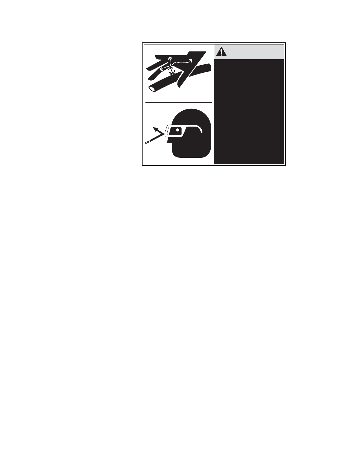
Safety
Hydraulic System Hazards
WARNING
HIGH PRESSURE FLUID
HAZARD
To prevent serious personal
injury or death:
•
Relieve system pressure
before adjusting,
repairing, or
disconnecting
components.
•
Wear proper hand and
eye protection. Use
cardboard to search for
leaks.
•
Keep all components in
good repair.
The hydraulic system is under pressure whenever the engine is running
and can hold pressure after the engine is shut down. After forks or
attachments are resting on the ground or support, make sure pressure is
relieved from all hydraulic lines and components before removing them
from the circuit.
W1047
Electrical System Hazards
Remember the following during inspection of the hydraulic system:
• Wait for fluid to cool down before disconnecting lines.
• DO NOT use your hand to check for leaks. Use a piece of cardboard or
paper to search for leaks.
• Wear appropriate eye protection.
• If any hydraulic fluid is injected into the skin, get medical attention
immediately.
• When venting or filling the hydraulic system, loosen the filler cap slowly
and remove it gradually.
• NEVER reset any relief valve in the hydraulic system to a pressure
higher than that specified in this manual.
Be aware of the following safety issues when working with batteries.
Explosive gases are always present around batteries. This is especially
true when the battery is being charged.
To avoid explosion…
• DO NOT use smoking materials near batteries.
• Keep arcs, sparks, and open flames away from batteries.
• Provide adequate ventilation.
1-4
31200079
Page 27

Safety
To avoid personal injury…
• Electrolyte in batteries contains sulfuric acid which is a poison and can
cause severe chemical burns. Wear a face shield and safety glasses to
prevent contact with your eyes and face.
• Wear chemical resistant gloves and clothing to keep acid off your skin
and regular clothing.
Important: If electrolyte is ever ingested or splashed into your eyes, get medical
attention immediately.
Eyes should be flushed with clean water as soon as possible. If
electrolyte comes in contact with your skin or clothing, immediately
wash it off with a large quantity of clean water.
NEVER
give fluids that would induce vomiting.
• Before working on the electrical system, disconnect the battery
cable(s). NEVER check the battery by placing a metal object across
the battery posts; the resulting spark could ignite anything flammable,
causing a fire or an explosion.
• Always disconnect the battery before welding on the machine.
CAUTION: When removing the battery, always remove the negative (–)
cable first. When installing, connect the positive (+) cable first.
Tire and Wheels Hazards
The stability of the forklift can be dramatically affected by incorrect inflation
or the lack of ballast fill. It is good practice to check your tires and wheels
on a daily basis.
Check tires for…
• The correct pressure
• Cuts or bulges
• Nails or punctures
• The proper ballast required
• Uneven or excessive wear.
Check wheels for…
• Condition of valve stems and caps, making sure valve caps are kept on
• Damage to the rims
• Missing or loose lug nuts or bolts
• Obvious misalignment.
All tire service should be performed by a qualified tire service center or by
an authorized person. This person must be properly trained in the
procedures and use of safety equipment designed for tire servicing.
31200079
When servicing wheels and tires, remember…
• NEVER over inflate a tire. Over inflation could result in an explosion.
• Punctures that could have allowed the ballast fill in a tire to leak out
must be repaired and the tire refilled with ballast before the forklift is
put back in operation.
1-5
Page 28

Safety
• NEVER reinflate a tire that has been run flat or seriously under inflated
WITHOUT removing the tire from the wheel. Have the tire and rim
closely inspected for damage before remounting.
• Clean the area around all wheel lug nuts or bolts. Periodically check
the torque per the specifications until the torque value stabilizes; then
check at regularly scheduled intervals.
Rollover Protective Structure (ROPS) and Falling Object Protective Structure (FOPS)
The machines are equipped with a Rollover Protective Structure (ROPS)
to guard the operator if the machine tips over. The Falling Object
Protective Structure (FOPS) is built into the ROPS. The FOPS protects the
operator from falling objects.
Despite the protection of the ROPS/FOPS, it cannot protect the operator
from every possible hazard. Do not consider the ROPS/FOPS a substitute
for safe practices and good common sense.
Any modification to a ROPS/FOPS, such as welding or drilling holes in the
structural members for mounting brackets, will affect the ROPS/FOPS
capability to provide the required protection.
Decals and Placards
General
Any modification or repair without the specific written approval of JLG will
void the ROPS/FOPS certification. Contact your authorized JLG dealer
before making any modifications or repairs. Failure to do so may void the
ROPS/FOPS certification.
The decals on the machine provide instructions for safe and correct
operation. Never make modifications affecting safe operation or capacity
without the expressed written approval of JLG. When approved
modifications are made, the user is responsible for seeing that appropriate
decals, load charts, and instructions are changed.
All plates and decals must be in place and legible at all times. Damaged
placards and decals should be replaced. Clean dirty decals.
In California, the machine MUST be equipped with a Proposition 65
Warning decal.
Cleaning Decals
1-6
If soiled with dirt, clean decals with mild soap. Use a mild alcohol solution if
soiled with grease. Do not use solvents that may damage the decal.
Replace all damaged, missing, or painted decals that cannot be read. On
refurbished or replaced parts, all missing decals must be replaced. See
your JLG dealer for replacement decals and placards.
31200079
Page 29

Attaching Decals
Decal Locations
Safety
The surface on which a decal is to be attached must be dry and free of all
dirt and grease. Remove the backing from the decal and apply decal in its
correct location. Once in place, rub entire surface of the decal with your
thumb, applying sufficient pressure to ensure good adhesion of the decal
to the mounting surface.
Decals and placards that provide information, instructions, and address
safety issues include the following:
• Attachment Capacity Plate (Fig. 1-7)
• Boom Extension Indicator Decal (Fig. 1-1)
• Boom Movement Control Decal (Fig. 1-3)
• Cab Transfer Extension Decal (Fig. 1-1)
• California Proposition 65 Warning Decal (Fig. 1-1)
• Carriage Safety Decal (Fig. 1-7)
• Carry Load Low Caution Decal (Fig. 1-2)
• Caution Plate (Fig. 1-1)
• Diesel Fuel Only Decal (Fig. 1-6)
• Disconnect Battery Decal (Fig. 1-4)
• Don’t Be Careless Decal (Fig. 1-2)
• Forklift Signals Decal (Fig. 1-1)
• Frame Tilt Control Decal (Fig. 1-3)
• Frame Transfer Extension Decal (Fig. 1-1)
• Hydraulic Breather Decal (Fig. 1-6)
• Hydraulic Oil Only Decal (Fig. 1-6)
• Load Chart Capacities Flip Card (Fig. 1-1)
• Low Brake Pressure Decal (Fig. 1-2)
• Lubrication Schedule Flip Card (Fig. 1-1)
• Notice Decal (General Operating Instructions) (Fig. 1-1)
• Outrigger Caution Decal (Fig. 1-2)
• Outrigger Control Decal (Fig. 1-3)
• Parking Brake Decal (Fig. 1-2)
• Pressure Test Ports Decal (Fig. 1-1)
• Rear Oscillation Lock Light Decal (Fig. 1-2)
• Slow Moving Vehicle Sign (Fig. 1-4)
• Steer Selector Plate (Fig. 1-5)
• Tire Ballast Required Decal (Fig. 1-1)
• Transfer and Fork Tilt Control Decal (Fig. 1-3)
• Transmission Declutch Decal (Fig. 1-2)
31200079
1-7
Page 30
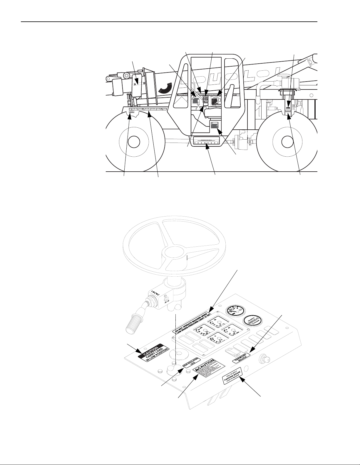
Safety
0
1
2
3
4
5
6
7
8
10
9
11
12
13
-1
01234567810 9
METERS
Boom
Extension
Indicator
T IRE B A LL AS T
R EQ UI RE D
REFER TO LUBRICATION SCHEDULE
Tire Ballast
Required
(Both Sides)
Cab Transfer
Extension
Notice
California
Proposition 65
Warning
Frame Transfer
Extension
Fig. 1-1: Decals and Placards
Forklift
Signals
FT
2
3
FORKLIFT SIGNALS
NOTICE
STOPRAISE LOAD LOWER LOAD
TILT FORKS RIGHTTILT FORKS LEFTTILT FORKS UP
TILT FORKS DOWN
MOVE LOAD BACKWARD
INSTRUCTIONS TO SIGNALMAN
1. Only one person to be signalman.
2. Make sure the operator can see you and is able to acknowledge the signal given.
3. Signalman must watch the load, the operator is watching you.
4. Never raise or lower the load over the other workmen. Warn them to keep out of the way.
5. Watch for overhead lines or other obstructions.
CALIFORNIA
Proposition 65 Warning
Diesel engine exhaust and some of its
constituents are known to the State of
California to cause cancer, birth
defects, and other reproductive harm.
REAR OSC.
REAR OSC.
PUMP 1 PUMP 2 BRAKES STEERING PILOT ACCUM.
LOCK (G1)
LOCK (G2)
Te st Po r t s
FT
45
MAXIMUM BOOM LOAD CAPACITIES AT
24" LOAD CENTER, FOR LIFT AND REACH
POSITIONS IN POUNDS AND FEET WITH
INDICATES REAR
METRIC CONVERSIONS.
OSCILLATION LOCK
40
MANUFACTURER'S RECOMMENDED
CAPACITIES ARE IN CONFORMANCE
ENGAGED
WITH ANSI/ASME B56.6 STABILITY TESTS
USING STANDARD HOMOGENEOUS
CUBES 4' × 4' × 4'.
35
MANUFACTURER'S RECOMMENDED
LOADS AND ANGLES SHOWN ARE AT
THE HORIZONTAL CENTER OF GRAVITY
OF THE ABOVE CUBE. CAPACITY
ADJUSTMENT MUST BE MADE FOR
30
EXTENDED LOAD CENTERS AND OTHER
VARIATIONS OF LOAD SIZE, ETC.
RATED LIFT CAPACITIES SHOWN ARE
WITH MACHINE ON A FIRM, LEVEL
25
SURFACE WITH UNDAMAGED, PROPERLY
MOVE LOAD FORWARD
INFLATED, BALLAST-FILLED TIRES.
70°
20
60°
50°
39617B
15
40°
30°
10
20°
10°
5
0°
-5°
0
AB
CD
EF
CAPACITIES SHOWN DEPICT FU LL B OOM EXTENSION PRIOR TO
G
HI
JK
LM
TRANSFER. AT FULL TRANSFER EXTENSION, CA PA CI T IE S AT ANY
NO
DISTANCE OUT ARE 70% OF RETRACTED TRANSFER VALUES.
FEET
05101520253035
39039B
CAUTION
Pressure
Load Chart
Capacities and
Lubrication Schedule
Flip Cards
Caution
Plate
Don’t Be
Careless
DON'T BE
CARELESS
SHUT DOWN ENGINE
BEFORE ANY SERVICE
T IRE B A LL AS T
R EQ UI RE D
REFER TO LUBRICATION SCHEDULE
Tire Ballast
Required
(Both Sides)
R1046
Carry
Load Low
Rear
Oscillation
Lock Light
Outrigger
Caution
Low Brake
Pressure
Warning
Transmission
Declutch
R1047
Parking
Brake
Fig. 1-2: Instrument Panel Decals
1-8
31200079
Page 31

Boom
Movement
Control
Safety
Tr a n sf e r
and Fork
Tilt Control
Outrigger
Control
Frame
Tilt Control
Fig. 1-3: Control Decals
V1087
31200079
Disconnect
Battery
MV0490
Fig. 1-4: Disconnect Battery Decal and Slow Moving Vehicle Sign
1-9
Page 32

Safety
Operator’s Seat
FRONT WHEEL STEER
ROUND STEER OBLIQUE STEER
Steer
Selector
Plate
R1049
Fig. 1-5: Steer Selector Plate
Hydraulic
Oil Only
Hydraulic
Breather
Diesel
Fuel Only
R1050
Fig. 1-6: Hydraulic Reservoir/Fuel Tank Decals
Attachment
Capacity
Plate
1-10
Carriage
Safety
Decal
R1051
Fig. 1-7: Fork Carriage Decals
31200079
Page 33

Section 2 — Identification and Specifications
Table of Contents
Serial Number Locations . . . . . . . . . . . . . . . . . . . . . . . . . . . . . . . . . . . . . . . . . . . . . . . . . . . . . . . . . . . 2-1
Machine Serial Number . . . . . . . . . . . . . . . . . . . . . . . . . . . . . . . . . . . . . . . . . . . . . . . . . . . . . . . . . . . . 2-1
Engine Serial Number, John Deere . . . . . . . . . . . . . . . . . . . . . . . . . . . . . . . . . . . . . . . . . . . . . . . . . . . 2-2
Axle Serial Number . . . . . . . . . . . . . . . . . . . . . . . . . . . . . . . . . . . . . . . . . . . . . . . . . . . . . . . . . . . . . . . 2-3
Attachment Serial Number Plate . . . . . . . . . . . . . . . . . . . . . . . . . . . . . . . . . . . . . . . . . . . . . . . . . . . . . 2-3
Identification . . . . . . . . . . . . . . . . . . . . . . . . . . . . . . . . . . . . . . . . . . . . . . . . . . . . . . . . . . . . . . . . . . . . . 2-4
Specifications . . . . . . . . . . . . . . . . . . . . . . . . . . . . . . . . . . . . . . . . . . . . . . . . . . . . . . . . . . . . . . . . . . . . 2-5
Engine Specifications . . . . . . . . . . . . . . . . . . . . . . . . . . . . . . . . . . . . . . . . . . . . . . . . . . . . . . . . . . . . . . 2-8
John Deere 4045T . . . . . . . . . . . . . . . . . . . . . . . . . . . . . . . . . . . . . . . . . . . . . . . . . . . . . . . . . . . . . . . . 2-8
List of Figures
Fig. 2-1: Machine Serial Number Plate . . . . . . . . . . . . . . . . . . . . . . . . . . . . . . . . . . . . . . . . . . . . . . . . . . 2-1
Fig. 2-2: Engine Serial Number — John Deere . . . . . . . . . . . . . . . . . . . . . . . . . . . . . . . . . . . . . . . . . . . . 2-2
Fig. 2-3: Axle Serial Number . . . . . . . . . . . . . . . . . . . . . . . . . . . . . . . . . . . . . . . . . . . . . . . . . . . . . . . . . . 2-3
Fig. 2-4: Attachment Serial Number Plate . . . . . . . . . . . . . . . . . . . . . . . . . . . . . . . . . . . . . . . . . . . . . . . . 2-3
Fig. 2-5: Top View . . . . . . . . . . . . . . . . . . . . . . . . . . . . . . . . . . . . . . . . . . . . . . . . . . . . . . . . . . . . . . . . . 2-4
Fig. 2-6: Left Side View . . . . . . . . . . . . . . . . . . . . . . . . . . . . . . . . . . . . . . . . . . . . . . . . . . . . . . . . . . . . . . 2-4
31200079 i
Page 34

ii 31200079
Page 35

Section 2 — Identification and Specifications
Serial Number Locations
Machine Serial Number
TIRE BALLAST
REQUIRED
REFER TO LUBRICATION SCHEDULE
Serial
Number
Plate
MV0290
Fig. 2-1: Machine Serial Number Plate
(Ref. Fig. 2-1) The machine serial number plate is located on the frame
behind the right front tire.
31200079
2-1
Page 36

Identification and Specifications
Engine Serial Number, John Deere
(Ref. Fig. 2-2) The engine serial number plate is located on the left side of
the engine near the starter and fuel pump.
Serial
Number
Plate
Fuel
Pump
Starter
V1006
Fig. 2-2: Engine Serial Number — John Deere
John Deere engines include an options code decal located on top of the
engine manifold cover. Do not damage, remove, or paint over this decal. It
is recommended that this information be written down for future reference.
2-2
31200079
Page 37

Axle Serial Number
Identification and Specifications
SERIAL NUMBER
PLATE
MV0360
Fig. 2-3: Axle Serial Number
(Ref. Fig. 2-3) The front axle serial number plate is located on the left front
side of the axle housing. The rear axle serial number plate is located on
the right rear side of the axle housing.
Attachment Serial Number Plate
MV0480
Fig. 2-4: Attachment Serial Number Plate
31200079
(Ref. Fig. 2-4) The location of this plate varies with each attachment.
2-3
Page 38

Identification and Specifications
Identification
R1026
Fig. 2-5: Top View
R1052
2-4
Fig. 2-6: Left Side View
31200079
Page 39

Specifications
Identification and Specifications
General Operating
Specifications
Dimensions
Lift and Carry Capacity . . . . . . . . . . . . . . . . . . . . . . . . . . . . . . . .10,000 lbs.
Maximum Lift Height . . . . . . . . . . . . . . . . . . . . . . . . . . . . . . . . . . . . 54 Feet
Boom Elevation Angle. . . . . . . . . . . . . . . . . . . . . . . . . . . . . . . . .-5° to +69°
TransAction . . . . . . . . . . . . . . . . . . . . . . . . . . . . . . . . . . . . . . . . . 80 Inches
Maximum Horizontal Forward Reach:. . . . . . . . . . . . . . . . . . . . . . . 45 Feet
Maximum Reach at Maximum Lift . . . . . . . . . . . . . . . . . . . . . . . . . 14 Feet
Capacity at Maximum Reach:. . . . . . . . . . . . . . . . . . . . . . . . . . . . 1500 lbs
Below Grade . . . . . . . . . . . . . . . . . . . . . . . . . . . . . . . . . . . . . . . . 40 Inches
Drive . . . . . . . . . . . . . . . . . . . . . . . . . . . . . . . . . . . . . . . . . . . . . . . .4-Wheel
Steer Modes . . . . . . . . . . .Front Wheel, 4-Wheel Round, 4-Wheel Oblique
Frame Tilt . . . . . . . . . . . . . . . . . . . . . . . . . . . . . . . . . . . . 10° Right and Left
Empty Vehicle Weight: . . . . . . . . . . . . . . . . . . . . Approximately 32,000lbs.
Note:
Dimensions listed are for forklift with all components fully retracted in travel
mode.
Overall Height . . . . . . . . . . . . . . . . . . . . . . . . . . . . . . . . . . . . . . . 97 Inches
Overall Width . . . . . . . . . . . . . . . . . . . . . . . . . . . . . . . . . . . . . . 101 Inches
Overall Length. . . . . . . . . . . . . . . . . . . . . . 24 Feet, 10 Inches (w/42” Fork)
Wheelbase . . . . . . . . . . . . . . . . . . . . . . . . . . . . . . . . . . . . . . . . 124 Inches
Outside Turning Radius . . . . . . . . . . . . . . . . . . . . . . . . . . 14 Feet, 2Inches
Ground Clearance . . . . . . . . . . . . . . . . . . . . . . . . . . . . . . . . . . 20.5 Inches
Capacities
Hydraulic System (Including Reservoir) . . . . . . . . . . . . . . . . . . .65 Gallons
Hydraulic Reservoir . . . . . . . . . . . . . . . . . . . . . . . . . . . . . . . . . .47 Gallons
Fuel Tank . . . . . . . . . . . . . . . . . . . . . . . . . . . . . . . . . . . . . . . . . .36 Gallons
Cooling System. . . . . . . . . . . . . . . . . . . . . . . . . . . . . . . . . . . . . . 18 Quarts
Engine Crankcase Oil w/Filter (John Deere) . . . . . . . . . . . . . . . 14 Quarts
Transmission Drain and Refill . . . . . . . . . . . . . . . . . . . . . . . . . . . 19 Quarts
Front Axle
Differential. . . . . . . . . . . . . . . . . . . . . . . . . . . . . . . . . . . . . . 9.5 Quarts
Planetary Hubs . . . . . . . . . . . . . . . . . . . . . . . . . . . . . . . . . . 54 Ounces
Rear Axle
Differential. . . . . . . . . . . . . . . . . . . . . . . . . . . . . . . . . . . . . 10.5 Quarts
Planetary Hubs . . . . . . . . . . . . . . . . . . . . . . . . . . . . . . . . . 40.5 Ounces
31200079
2-5
Page 40

Identification and Specifications
Pressures Hydraulic:
Boom Hoist and Extend Valve Relief . . . . . . . . . . . . . . . . 3000 psi
4- or 5-Section Relief Valve . . . . . . . . . . . . . . . . . . . . . . . 3150 psi
Carriage Tilt Valve Section, Up Port Relief . . . . . . . . . . . . 2800 psi
Carriage Tilt Valve Section, Down Port Relief. . . . . . . . . . 2800 psi
Steering . . . . . . . . . . . . . . . . . . . . . . . . . . . . . . . . . . . . . . 2355 psi
Brakes. . . . . . . . . . . . . . . . . . . . . . . . . . . . . . . . . . . . . . . . . . 425psi
Joystick Control Pilot. . . . . . . . . . . . . . . . . . . . . . . . . . . . . . 510 psi
Hydraulic Return Filter . . . . . . . . . . . . . . . . . . . . . . . . . . . 0–15 psi
Accumulator:
Dry Nitrogen Pre-Charge . . . . . . . . . . . . . . . . . . . . . . . . . . .400 psi
Accumulator Charge Valve . . . 1000 (Low Limit), 1125 (High Limit)
Transmission
Travel Speeds
Axles
Manufacturer. . . . . . . . . . . . . . . . . . . . . . . . . . . . . . . . . Zahnradfabrik (ZF)
Model . . . . . . . . . . . . . . . . . . . . . . . . . . . . . . . . . . . . . . . . . . . . 4WG-98TC
Type . . . . . . . . . . . . . . 4-Speed Electric Powershift with Torque Converter
Speeds . . . . . . . . . . . . . . . . . . . . . . . . . . . . . . . . . . . 4 Forward, 3 Reverse
Filter . . . . . . . . . . . . . . . . . . . . . . . . . . . . . . . . . . . . . . . . . . . . . . . . Spin-On
1st Gear . . . . . . . . . . . . . . . . . . . . . . . . . . . . . . . . . . . . 3.5 mph (5,6 km/hr)
2nd Gear. . . . . . . . . . . . . . . . . . . . . . . . . . . . . . . . . . . . . 6 mph (9,7 km/hr)
3rd Gear . . . . . . . . . . . . . . . . . . . . . . . . . . . . . . . . . . 15.2 mph (24,5 km/hr)
4th Gear (Forward Only) . . . . . . . . . . . . . . . . . . . . . . . . .22 mph (35 km/hr)
Manufacturer. . . . . . . . . . . . . . . . . . . . . . . . . . . . . . . . . Zahnradfabrik (ZF)
Model
Front . . . . . . . . . . . . . . . . . . . . . . . . . . . . . . . . . . . . . . . . . . . . . .MS-T-3060
Rear . . . . . . . . . . . . . . . . . . . . . . . . . . . . . . . . . . . . . . . . . . . . . .MS-T-3055
Type . . . . . . . . . . . . . . . . . Off-Highway with Drive and Steering Functions
2-6
31200079
Page 41

Identification and Specifications
Wheels/Tires
Service Brakes
Parking Brake
Engine Models
Hydraulic Pump
Electrical System
Lugs . . . . . . . . . . . . . . . . . . . . . . . . . . . . . . . . . . . 10 (Torque to 320 ft-lbs)
14 × 24 Tires (Bias & Radial):
Tire Size . . . . . . . . . . . . . . . . . . . . . . . . . . . . . . . . . . . . . . . . . . 14 × 24
Water . . . . . . . . . . . . . . . . . . . . . . . . . . . . . . . . . . . . . . . . . 57 Gallons
Calcium Chloride . . . . . . . . . . . . . . . . . . . . . . . . . . . . . . . . . . . 150 lbs
Foam. . . . . . . . . . . . . . . . . . . . . . . . . . . . . . . . . . . . . . . . . . . . . 720 psi
Pressure . . . . . . . . . . . . . . . . . . . . . . . . . . . . . . . . . . . . . . . . . . . 70 psi
Manufacturer. . . . . . . . . . . . . . . . . . . . . . . . . . . . . . . . . Zahnradfabrik (ZF)
Type . . . . . . . . . . . . . . . . . . . . . Hydraulically Actuated, Internal, Wet Disc
Manufacturer. . . . . . . . . . . . . . . . . . . . . . . . . . . . . . . . . Zahnradfabrik (ZF)
Type . . . . . . . . . . . . . . . . . . . . . . . . . . . . . . . . . . . . (SAHR) Spring Applied
Hydraulically Released
(See “Engine Specifications” on page 2-8)
John Deere 4045T F 275 . . . . . . . . . . . . . . . . . . . . . . 115 HP @ 2500 rpm
Type . . . . . . . . . . . . . . . . . . . . . . . . . . . . . . . . . . . . . . . . . . . Tandem Gear
System Voltage . . . . . . . . . . . . . . . . . . . . . . . . . . 12-Volt, Negative Ground
Battery . . . . . . . . . . . . . . . . . . . . . . . . . . . . . . . . . . . . . . . 12-Volt, 925CCA
Alternator:
Bosch . . . . . . . . . . . . . . . . . . . . . . . . . . . . . . . . . . . . . . . . . . . . . . . 95 Amp
Working Temperatures
Hydraulic Oil . . . . . . . . . . . . . . . . . . . . . . . . . . . . . . . . . . . . . . . 140–180°F
Transmission Oil . . . . . . . . . . . . . . . . . . . . . . . . . . . . . . . . . . . . 104–230°F
Engine Oil . . . . . . . . . . . . . . . . . . . . . . . . . . . . . . . . . . .See Engine Manual
Engine Coolant . . . . . . . . . . . . . . . . . . . . . . . . . . . . . . . . . . . . . 180–185°F
31200079
2-7
Page 42

Identification and Specifications
Engine Specifications
John Deere 4045T
Fuel. . . . . . . . . . . . . . . . . . . . . . . . . . . . . . . . . . . . . . . . . . . . . . . . . . Diesel
Aspiration . . . . . . . . . . . . . . . . . . . . . . . . . . . . . . . . . . . . . . . Turbocharged
Cooling . . . . . . . . . . . . . . . . . . . . . . . . . . . . . . . . . . . . . . . . . . . . . . . .Liquid
Horsepower . . . . . . . . . . . . . . . . . . . . . . . . . . . . . . . . 115 HP @ 2500 rpm
Maximum Torque . . . . . . . . . . . . . . . . . . . . . . . . . . 291 ft-lbs @ 1400 rpm
Piston Displacement. . . . . . . . . . . . . . . . . . . . . . . . . . . . 275 Cubic Inches
Number of Cylinders. . . . . . . . . . . . . . . . . . . . . . . . . . . . 4 Vertical In-Line
Cycle. . . . . . . . . . . . . . . . . . . . . . . . . . . . . . . . . . . . . . . . . . . . . . . 4 Stroke
Combustion System . . . . . . . . . . . . . . . . . . . . . . . . . . . . . . .Direct Injection
Compression Ratio . . . . . . . . . . . . . . . . . . . . . . . . . . . . . . . . . . . . . . 17.6:1
Oil Filter . . . . . . . . . . . . . . . . . . . . . . . . . . . . . . . . . . . . . . . . . . . . . Spin-On
Air Cleaner . . . . . . . . . . . . . . . . . . . . . . . . . . . . . . . . . . . . . . .Dry Cartridge
High rpm. . . . . . . . . . . . . . . . . . . . . . . . . . . . . . . . . . . . . . . . . . . 2650-2750
Idle rpm . . . . . . . . . . . . . . . . . . . . . . . . . . . . . . . . . . . . . . . . . . . . 890-910
2-8
31200079
Page 43

Section 3 — General Maintenance
Table of Contents
General Instructions . . . . . . . . . . . . . . . . . . . . . . . . . . . . . . . . . . . . . . . . . . . . . . . . . . . . . . . . . . . . . . . 3-1
Service Preparation Procedures . . . . . . . . . . . . . . . . . . . . . . . . . . . . . . . . . . . . . . . . . . . . . . . . . . . . 3-1
Service And Repair Procedures . . . . . . . . . . . . . . . . . . . . . . . . . . . . . . . . . . . . . . . . . . . . . . . . . . . . . 3-2
Replacement Parts . . . . . . . . . . . . . . . . . . . . . . . . . . . . . . . . . . . . . . . . . . . . . . . . . . . . . . . . . . . . . . . . 3-3
General . . . . . . . . . . . . . . . . . . . . . . . . . . . . . . . . . . . . . . . . . . . . . . . . . . . . . . . . . . . . . . . . . . . . . . . . 3-3
Lubrication . . . . . . . . . . . . . . . . . . . . . . . . . . . . . . . . . . . . . . . . . . . . . . . . . . . . . . . . . . . . . . . . . . . . . . . 3-3
General . . . . . . . . . . . . . . . . . . . . . . . . . . . . . . . . . . . . . . . . . . . . . . . . . . . . . . . . . . . . . . . . . . . . . . . . 3-3
Fluid and Lubricant Specifications . . . . . . . . . . . . . . . . . . . . . . . . . . . . . . . . . . . . . . . . . . . . . . . . . . 3-4
General Specifications . . . . . . . . . . . . . . . . . . . . . . . . . . . . . . . . . . . . . . . . . . . . . . . . . . . . . . . . . . . . . 3-4
Engine Oil Specifications . . . . . . . . . . . . . . . . . . . . . . . . . . . . . . . . . . . . . . . . . . . . . . . . . . . . . . . . . . . 3-4
Transmission Oil Specifications . . . . . . . . . . . . . . . . . . . . . . . . . . . . . . . . . . . . . . . . . . . . . . . . . . . . . . 3-5
Fuel Requirements . . . . . . . . . . . . . . . . . . . . . . . . . . . . . . . . . . . . . . . . . . . . . . . . . . . . . . . . . . . . . . . . 3-6
Grease . . . . . . . . . . . . . . . . . . . . . . . . . . . . . . . . . . . . . . . . . . . . . . . . . . . . . . . . . . . . . . . . . . . . . . . . . 3-6
Care and Cleaning . . . . . . . . . . . . . . . . . . . . . . . . . . . . . . . . . . . . . . . . . . . . . . . . . . . . . . . . . . . . . . . . . 3-7
Cleaning Exterior Surfaces . . . . . . . . . . . . . . . . . . . . . . . . . . . . . . . . . . . . . . . . . . . . . . . . . . . . . . . . . 3-7
Cleaning the Cab . . . . . . . . . . . . . . . . . . . . . . . . . . . . . . . . . . . . . . . . . . . . . . . . . . . . . . . . . . . . . . . . . 3-7
Cleaning Decals . . . . . . . . . . . . . . . . . . . . . . . . . . . . . . . . . . . . . . . . . . . . . . . . . . . . . . . . . . . . . . . . . . 3-8
Attaching Decals . . . . . . . . . . . . . . . . . . . . . . . . . . . . . . . . . . . . . . . . . . . . . . . . . . . . . . . . . . . . . . . . . 3-8
Storage . . . . . . . . . . . . . . . . . . . . . . . . . . . . . . . . . . . . . . . . . . . . . . . . . . . . . . . . . . . . . . . . . . . . . . . . . . . 3-8
Preparing the Machine for Long-Term Storage . . . . . . . . . . . . . . . . . . . . . . . . . . . . . . . . . . . . . . . . . . 3-8
Preparing the Machine After Long-Term Storage . . . . . . . . . . . . . . . . . . . . . . . . . . . . . . . . . . . . . . . . 3-9
Torque Specifications . . . . . . . . . . . . . . . . . . . . . . . . . . . . . . . . . . . . . . . . . . . . . . . . . . . . . . . . . . . . . 3-10
General Torques for Standard Bolts, Capscrews, and Nuts . . . . . . . . . . . . . . . . . . . . . . . . . . . . . . . . 3-10
Hydraulic Fitting Torques . . . . . . . . . . . . . . . . . . . . . . . . . . . . . . . . . . . . . . . . . . . . . . . . . . . . . . . . . . 3-14
Jump Starting Procedures . . . . . . . . . . . . . . . . . . . . . . . . . . . . . . . . . . . . . . . . . . . . . . . . . . . . . . . . 3-16
Conversion Charts . . . . . . . . . . . . . . . . . . . . . . . . . . . . . . . . . . . . . . . . . . . . . . . . . . . . . . . . . . . . . . . . 3-18
List of Figures
Fig. 3-1: SAE Grade Identification. . . . . . . . . . . . . . . . . . . . . . . . . . . . . . . . . . . . . . . . . . . . . . . . . . . . . 3-10
Fig. 3-4: Metric Class Identification . . . . . . . . . . . . . . . . . . . . . . . . . . . . . . . . . . . . . . . . . . . . . . . . . . . . 3-13
31200079 i
Page 44

List of Tables
Table 3-1: General Fluid and Lubricant Specifications . . . . . . . . . . . . . . . . . . . . . . . . . . . . . . . . . . . . . . .3-1
Table 3-2: John Deere Engine Oil Specifications . . . . . . . . . . . . . . . . . . . . . . . . . . . . . . . . . . . . . . . . . . .3-2
Table 3-3: ZF Transmission Oil Specifications . . . . . . . . . . . . . . . . . . . . . . . . . . . . . . . . . . . . . . . . . . . . .3-3
Table 3-4: Torque for JIC and SAE Female Swivel Nuts . . . . . . . . . . . . . . . . . . . . . . . . . . . . . . . . . . . . .3-4
Table 3-5: Torque for Non-adjustable O-ring Fittings . . . . . . . . . . . . . . . . . . . . . . . . . . . . . . . . . . . . . . . .3-5
Table 3-6: Torque for Adjustable O-ring Fittings . . . . . . . . . . . . . . . . . . . . . . . . . . . . . . . . . . . . . . . . . . .3-6
Table 3-7: Torque for O-ring Plugs . . . . . . . . . . . . . . . . . . . . . . . . . . . . . . . . . . . . . . . . . . . . . . . . . . . . . .3-7
Table 3-8: Pipe Thread Fittings (Steel) . . . . . . . . . . . . . . . . . . . . . . . . . . . . . . . . . . . . . . . . . . . . . . . . . . .3-8
Table 3-9: Inch Fraction, Decimal, and Metric Conversion Chart . . . . . . . . . . . . . . . . . . . . . . . . . . . . . . .3-9
Table 3-10: Miscellaneous Conversions . . . . . . . . . . . . . . . . . . . . . . . . . . . . . . . . . . . . . . . . . . . . . . . . .3-10
ii 31200079
Page 45

Section 3 — General Maintenance
General Instructions
Performance of your machine is dependent on proper maintenance and
lubrication at designated intervals. Proper operating procedures and a
regularly scheduled maintenance and lubrication program will increase the
life of machine components and reduce machine down time.
Should a defect or failure occur to your machine, take it out of service
immediately. The machine must not continue to operate under any
circumstances as serious damage to the machine or personal injury may
result.
Attach a warning tag to the steering wheel of the forklift. If the forklift
should not be started, remove the ignition key.
Before doing any maintenance or repair work, get permission. Do not
perform any maintenance without authorization.
If you have been authorized to do maintenance, read the service manual,
study the instructions, and examine all the instructions and messages on
the machine.
When performing inspection, maintenance, lubrication, or adjustments to
the machine, be alert to evidence of excessive wear including odors and
noises that may indicate damage, malfunction, or other maintenance
problems.
Service Preparation Procedures
• Choose a clean, level work area. Check clearances and make sure you
have sufficient room. Make certain there is adequate light and
ventilation.
• Park machine on level surface, set the parking brake, level the frame,
and shut off the engine.
• Clean the walking and working surfaces. Remove oil, grease, ice,
snow, mud, and water to eliminate slippery areas. Sand any remaining
slippery areas.
• Make sure you have the correct tools. Keep tools clean and inspect
power cords.
• Make sure jacks and hoists are available and in good condition. Never
use jacks with cracked, bent, or twisted parts. Never use frayed,
twisted, or pinched cables. Never use bent or distorted hooks.
• Make use of mechanical assists. To protect your back from possible
injury, use proper lifting methods.
31200079
3-1
Page 46

General Maintenance
Service And Repair Procedures
CAUTION: Unless specifically told not to, lower the boom to the ground,
WARNING: Release all hydraulic pressure before doing any maintenance
WARNING: Liquid cooling systems build up pressure as the engine gets
• Be careful not to damage machined and polished surfaces.
• Tighten all bolts, fittings and connections to specifications.
• Avoid fires and explosive hazards.
• Handle all solvents and dry chemicals according to procedures identified on manufacturers' containers. Work in a well-ventilated area. Make
sure you know where fire extinguishers are kept and how to use them.
• Use an approved solvent to clean parts. Never use gasoline or diesel
fuel.
• Shut off the engine and electrical equipment while filling the fuel tank.
Use extra caution when fueling while the engine is hot. Always ground
the fuel nozzle against the filler neck to avoid sparks.
apply the parking brake, and stop the engine before servicing,
adjusting, or repairing the machine.
or repairs to the hydraulic system.
hot. Before removing the radiator cap, stop the engine and let
the system cool. Remove the radiator cap only after the
coolant is cold.
WARNING: Never smoke while handling fuel or working on the fuel
system. The fumes in an empty fuel container are explosive.
Never cut or weld on fuel lines, tanks, or containers.
• Avoid spilling fuel. If a spill occurs, wipe it up immediately.
• Never weld on forks, boom, support frame or overhead guard without
written consent from JLG.
• Install all guards, covers and shields after servicing. Repair or replace
any that are damaged.
• Refill systems with approved or recommended fluids. Start the engine
and check for leaks
WARNING: Diesel fuel or hydraulic fluid under pressure can penetrate the
skin or damage eyes. Fluid leaks under pressure may not be
visible. Use a piece of cardboard or wood to find leaks but do
not use your hand. Wear appropriate eye protection. If fluid
enters skin or eye, get medical attention immediately.
• Operate all controls and make sure the forklift is functioning properly.
Road test the machine if necessary. After testing, shut down and
recheck the work you performed. Recheck all fluid levels before releasing machine for operation.
3-2
31200079
Page 47

Replacement Parts
General
Lubrication
General
General Maintenance
Record the machine model, serial number, and component serial numbers
for reference when ordering replacement parts. See “Serial Number
Locations” in Section 2.
Use only JLG authorized replacement parts and fluids. Use of parts other
than JLG authorized parts may adversely effect machine reliability,
performance, and safety and may void the warranty.
JLG assumes no liability for equipment damages caused by the use of
unauthorized replacement parts.
For best machine performance, follow the instructions found on the
machine’s service lubrication schedule.
• Clean around all oil fill holes before checking or adding oil.
• Keep all lubricants and lubricating equipment clean and free of foreign
matter both while in use and while in storage.
• Wipe off any excess lubricants that spill or overflow. Oily or greasy surfaces tend to collect dirt and foreign matter which can work its way into
bearings and gears.
31200079
3-3
Page 48

General Maintenance
Fluid and Lubricant Specifications
General Specifications
Table 3-1: General Fluid and Lubricant Specifications
SYSTEM OR
COMPONENT
Fuel System
1
Hydraulic System
FLUID OR
LUBRICATION
See "Fuel Requirements"
Tractor Hydraulic
Mobilfluid 424
SPECIFICATION
®
Fluid
Engine Cooling
System
Engine Oil
1
1
See engine manufacturer's operator's
manual.
See Engine Oil Specifications
Transmission See Transmission Oil
Specifications
Differential
(Front & Rear)
Planetary Hub
Tractor Hydraulic
Fluid
Tractor Hydraulic
Mobilfluid 424
Mobilfluid 424
®
®
Fluid
Grease Points Grease Lithium-based
1
Consult engine manufacturer's operator manual for additional information.
MV0500
Engine Oil Specifications
John Deere Engines Use the table below to select the oil viscosity based on expected air
temperature range during the period between oil changes. Consult the
John Deere Operator’s Manual for additional information.
New John Deere engines use special break-in oil for the initial period of
Note:
operation. Consult engine Operator’s Manual for additional information.
3-4
31200079
Page 49

General Maintenance
Table 3-2: John Deere Engine Oil Specifications
ENGINE OIL, DEERE
Oil Grade
Temperature
Range °F
Temperature
Range °C
Transmission Oil Specifications
The following table shows approved lubricants and associated
temperature ranges for use with ZF 4WG series transmissions.
SAE 5W-30
SAE 10W-30
SAE 15W-40
SAE 30W
SAE 40W
Arctic oil (e.g.
MIL-L-46167B)
-22 to +86 °F -30 to +30 °C
-4 to +86 °F
+5 to +122 °F
+32 to +86 °F
-50 to +104 °F
Below -22 °F
-20 to +30 °C
-15 to +50 °C
0 to +30 °C
+10 to +40 °C
Below -30 °F
Approved Engine Oil Specifications
API CD/CE
CCMC Specifications D4, D5
SAE 5W-30
SAE 10W-30
SAE 15W-40
SAE 30W
SAE 40W
MIL-46167B
MV0510
Table 3-3: ZF Transmission Oil Specifications
ZF 4WG-98TC TRANSMISSIONS
Oil Grade
Recommended
Mobilfluid 424
Engine Oils
Automatic Transmission Fluid (ATF)
AT F
Approved Lubricants (Engine Oils)
API CD/ CE/ CF/ SF/ SG
MIL-L-2104 C/ D/ E
MIL-L-46152 C/ D/ E
SAE 10W
SAE 10W-30
SAE 10W-40
SAE 15W-40
SAE 20W-20
Automatic Transmission Fluid (ATF) may only be used at
ambient temperatures below +14 °F (-10 °C)
®
SAE 20W-20 +14 °F (-10 °C)
SAE 15W-40
SAE 10W,
10W-30,
10W-40
Minimum Oil
Temperature for
Starting Engine
-4 °F (-20 °C) +86 °F (+30 °C)
+5 °F (-15 °C)
-4 °F (-20 °C)
-22 °F (-30 °C) +14 °F (-10 °C)
Minimum Oil
Temperature for
Engaging
Transmission
+41 °F (+5 °C)
+32 °F (0 °C)
+23 °F (-5 °C)
MV0520
31200079
3-5
Page 50

General Maintenance
Fuel Requirements
Grease
Diesel fuels are blended to meet the local temperature requirements. The
standard grades are:
1. 1D for temperatures -22 to +86 °F (-30 to +30 °C)
2. 2D for temperatures +14 to +122 °F (-10 to +50 °C).
There are two main classifications of diesel fuel in general use:
1. Low-sulphur, “on-highway” diesel fuel
2. Medium-sulfur, “off-highway” diesel fuel. This fuel contains blue dye.
The engine manufacturer specifies the diesel fuel requirements. Additional
information can be found in the engine manufacturer’s Operator’s Manual.
Consult your local fuel distributor for the properties of the diesel fuels
available in your area
• Use a lithium base grease with E.P. additives and rust inhibitors. A #2
grade should be used at temperatures above 32° F (0° C) and #1
grade at or below 32° F (0° C).
• Wipe off all fittings before applying grease. Dirt on the fitting can be
forced through the opening in the fitting and cause premature bearing
failure.
• Lubricate all grease fittings with the specified grease.
3-6
31200079
Page 51

Care and Cleaning
Wash the machine regularly. A clean well-maintained machine helps
prevent safety hazards and makes problem areas more recognizable.
Remove all items that do not belong on the machine. Secure all loose
items such as lunch boxes, tools, and additional equipment.
Cleaning Exterior Surfaces
General Maintenance
• High pressure water or steam may be used to clean the exterior. Give
extra attention to the underside.
• DO NOT damage or wash off decals when using high pressure water
or steam. See “Cleaning Decals” below.
• Clean the mirror carefully.
• DO NOT allow mud or snow to accumulate on engine or transmission.
• Make sure radiator and transmission oil cooler fins are clean.
• Commercial engine degreasers may be used to clean the engine and
transmission. Follow the product instructions closely.
• NEVER spray water or cleaner on a hot engine or transmission, especially on a hot turbocharger.
• Commercial general purpose degreasers and detergents may be used
to help clean thick deposits. Do not use chemicals that can damage
paint or decals.
• Avoid spraying water on electrical components such as the alternator,
starter, gauges, and electrical items under the dash.
• Be careful around the fuel fill and hydraulic reservoir breather. Water
may get into tanks and damage fuel and/or hydraulic components.
• To help prevent freezing, allow water to drain or dry before operating in
cold weather.
Cleaning the Cab
31200079
• Clean dust and dirt from all areas of the cab. Be careful to keep water
spray away from electrical components under the dash.
• Clean vinyl items with commercial vinyl cleaner. Treat with vinyl protectant to guard against ultraviolet damage. Do not use vinyl protectant
on rubber or plastic controls if it will leave them slippery.
• Clean the windows inside and out. Remove any decals from windows
that are not original equipment.
• Carefully clean plastic gauge and indicator lenses. Use a soft cloth and
a cleaner suitable for plastic. Dust and dirt can scratch the clear
plastic.
• Make sure step and hand holds are clean.
• Remove accumulated dirt from brake and accelerator pedals.
3-7
Page 52

General Maintenance
Cleaning Decals
Attaching Decals
Storage
If soiled with dirt, clean decals with mild soap. Use a mild alcohol solution if
soiled with grease. Do not use solvents that may damage the decal.
Replace all damaged, missing, or painted decals that cannot be read. On
refurbished or replaced parts, all missing decals must be replaced.
See your JLG dealer for replacement decals and placards.
The surface on which a decal is to be attached must be dry and free of all
dirt and grease. Remove the backing from the decal and apply decal in its
correct location. Once in place, rub entire surface of the decal with your
thumb, applying sufficient pressure to ensure good adhesion of the decal
to the mounting surface.
The following procedures are to be used if the machine will not be
operated for a long period of time.
Preparing the Machine for Long-Term Storage
Prior to placing the machine into storage, perform the following:
1. Wash off the entire machine.
2. Lubricate all grease fittings as instructed in “Grease” on page 3-6 of
this section
3. Change engine oil according to specifications described in Table 3-2
on page 5.
4. Apply grease to all exposed hydraulic cylinder rod areas.
5. Disconnect battery cables. If the machine is to be stored under cold
conditions, remove the battery and store it in a heated area.
6. Check engine coolant level and make sure it has an adequate coolantto-water ratio for the conditions it will be stored in.
7. Check transmission fluid level and fill if necessary according to the
guidelines described in Table 3-3 on page 5 of this section.
3-8
8. Preferable, store the machine inside where it will remain dry. If it must
be stored outside, park it on a concrete slab or on lumber laid on flat,
level ground and cover it with a tarp.
31200079
Page 53

Preparing the Machine After Long-Term Storage
After removing the machine from storage and before placing it back in
service, perform the following:
1. If covered with a tarp, remove it.
2. Wipe off grease from cylinder rods.
3. Loosen drain plug from bottom of fuel tank and drain into suitable
container until fluid is clean.
4. Loosen drain plug on bottom of hydraulic oil reservoir and drain into
suitable container until fluid is clean.
5. Loosen drain on fuel/water separator on engine and drain into suitable
container until fluid is clean.
6. Check nitrogen recharge.
7. Check engine coolant and hydraulic fluid levels. Add fluids if
necessary.
8. If battery was stored separately from the machine, install it.
9. Connect battery cables.
General Maintenance
10. Start engine using start safety procedures as described in the
Owner/Operator Manual.
11. After the engine has warmed up, test all hydraulic functions and
controls.
12. Check transmission operation.
13. Shut the machine down and check for any hydraulic leaks and repair,
as necessary.
WARNING: Hydraulic fluid under pressure can penetrate the skin or
damage eyes. Fluid leaks under pressure may not be visible.
Use a piece of cardboard or wood to find leaks but do not use
your hand. Wear appropriate eye protection. If fluid enters skin
or eye, get medical attention immediately.
14. Check for any other leaks and repair as necessary.
15. Check other fluid levels and replenish as necessary. Refer to your
service/lubrication charts.
31200079
3-9
Page 54

General Maintenance
Torque Specifications
General Torques for Standard Bolts, Capscrews, and Nuts
Figure 3-2 and Figure 3-3 lists torque values for standard bolts and nuts.
They are intended as a guide for typical applications. Values for specific
applications take precedence over those in the following tables.
Values are for plated or lubricated bolts and nuts.
Note:
SAE BOLT HEAD MARKINGS
SAE GRADE 2
SAE GRADE 5 SAE GRADE 5.1 SAE GRADE 5.2
Y1001
SAE GRADE 8.2SAE GRADE 8
Fig. 3-1: SAE Grade Identification
SAE NUT MARKINGS
SAE GRADE 2 (NO MARK)
SAE GRADE 5
Y1000
SAE GRADE 8
3-10
31200079
Page 55

General Maintenance
31200079
Fig. 3-2: General Torques for Standard Bolts, Capscrews, and Nuts
3-11
Page 56

General Maintenance
S
G
5S
G
8
RADE
UNPLATED CAP SCREWS
VALUES FOR ZINC PLATED BOLTS ONLY
AE
RADE
AE
3-12
Note: These torque values do not apply to cadium plated fasteners.
Fig. 3-3: General Torques for Metric Bolts, Capscrews, and Nuts
31200079
Page 57

General Maintenance
PROPERTY CLASS
AND HEAD MARKINGS
4.8
4.8
4.8
8.8
8.8
9.8
9.88.8
9.8
10.9 10
10.9
12.9 12
PROPERTY CLASS
AND NUT MARKINGS
5
5
5
10
10
10
10
10
12.9
12.9
12
12.9
12
Fig. 3-4: Metric Class Identification
Y1--2
31200079
3-13
Page 58

General Maintenance
Hydraulic Fitting Torques
JIC and SAE Female
Swivel Nuts
It is recommended that the nut be torqued to the approximate minimum
value. If leakage occurs, tighten nut without exceeding maximum torque
value.
Use two wrenches to tighten hydraulic line nuts.
Note:
Table 3-4: Torque for JIC and SAE Female Swivel Nuts
Size
-4 7/16-20 130 in-lbs 150 in-lbs 2
-5 1/2-20 165 " 195 " 2
-6 9/16-18 235 " 265 " 1 1/4
-8 3/4-16 44 ft-lbs 48 ft-lbs 1
-10 7/8-14 50 " 58 " 1
-12 1 1/16-12 79 " 88 " 1
-16 1 5/16-12 117 " 125 " 1
-20 1 5/8-12 158 " 175 " 1
-24 1 7/8-12 188 " 213 " 1
-32 2 1/2-12 250 " 283 " 1
1. Number of flats on nut to be turned past finger tight. This
method will produce the approximate torque.
SAE Port
Thread Size
Approx. Min.
Torque
Max. Torque
Flats
1
Non-adjustable O-ring
Fittings
To install straight thread, non-adjustable O-ring fittings:
1. Check condition of O-ring and replace as necessary. Do not install a
fitting with a damaged O-ring.
2. Lubricate O-ring with clean hydraulic fluid and torque per Table 3-5.
Table 3-5: Torque for Non-adjustable O-ring Fittings
Size
-2 5/16-24 85 in-lbs 95 in-lbs
-4 7/16-20 205 " 235 "
-6 9/16-18 25 ft-lbs 29 ft-lbs
-8 3/4-16 46 " 50 "
-10 7/8-14 85 " 95 "
-12 1 1/16-12 105 " 115 "
-16 1 5/16-12 154 " 166 "
-20 1 5/8-12 213 " 237 "
-24 1 7/8-12 238 " 262 "
SAE Port
Thread Size
Min. Torque Max. Torque
3-14
31200079
Page 59

General Maintenance
Adjustable O-ring Fittings
To install straight thread, adjustable O-ring fittings:
1. Check condition of O-ring and replace as necessary. Do not install a
fitting with a damaged O-ring.
2. Lubricate O-ring with clean hydraulic fluid.
3. Back off the locknut fully.
4. Screw fitting into port until backup washer contacts face of port.
5. Position fitting by unscrewing a maximum of one turn.
6. Hold the fitting in position with a wrench and torque locknut per Table
3-6.
Table 3-6: Torque for Adjustable O-ring Fittings
Size
-2 5/16-24 60 in-lbs 70 in-lbs
-4 7/16-20 160 " 180 "
-6 9/16-18 25 ft-lbs 29 ft-lbs
-8 3/4-16 40 " 44 "
-10 7/8-14 58 " 63 "
-12 1 1/16-12 75 " 85 "
-16 1 5/16-12 109 " 121 "
-20 1 5/8-12 213 " 237 "
-24 1 7/8-12 238 " 262 "
SAE Port
Thread Size
Min. Torque Max. Torque
O-ring Plugs To install straight thread O-ring plugs:
1. Check condition of O-ring and replace as necessary. Do not install a
plug with a damaged O-ring.
2. Lubricate O-ring with clean hydraulic fluid and torque per Table 3-7.
Table 3-7: Torque for O-ring Plugs
SAE Port Hollow Hex Head Hex Head
Size Thread Size Min. Torque Max. Torque Min. Torque Max. Torque
-2 5/16-24 30 in-lbs 40 in-lbs 85 in-lbs 95 in-lbs
-4 7/16-20 125 " 145 " 205 " 235 "
-6 9/16-18 210 " 230 " 25 ft-lbs 29 ft-lbs
-8 3/4-16 44 ft-lbs 48 ft-lbs 46 " 50 "
-107/8-1470"80"85"95"
-12 1 1/16-12 80 " 90 " 105 " 115 "
-16 1 5/16-12 129 " 141 " 154 " 166 "
-20 1 5/8-12 213 " 237 " 213 " 237 "
-24 1 7/8-12 238 " 262 " 238 " 262 "
31200079
3-15
Page 60

General Maintenance
Pipe Thread Fittings To install National Pipe Thread (NPT) fittings:
1. Apply sealant sparingly to male pipe threads only, avoiding the first few
threads at the end of the fitting.
Do not use Teflon tape or excessive amounts of sealant. System
Note:
contamination will result.
2. Install fitting and tighten per Table 3-8.
Table 3-8: Pipe Thread Fittings (Steel)
Jump Starting Procedures
CAUTION:
• Improper jump starting procedures can cause an explosion resulting in
personal injury.
• Sparks near batteries can cause explosions.
• Do not allow jump cable ends to touch each other or the machine.
• Battery acid can cause personal injury if it contacts skin or eyes.
Always wear eye protection when jump starting a machine.
• Always connect battery positive (+) to battery positive (+) and battery
negative (-) to ground on the machine. Make the final ground connection away from the battery.
• Allowing the two machines to touch during jump starting can cause
damage to bearings and electrical circuits.
• This machine has a 12 volt starting system. Use the same voltage (12
volts) for jump starting. Use of higher voltage can damage the electrical system.
• Never charge a frozen battery.
Fitting
Size
-2 1/8-27 2–3
-4 1/8-27 2–3
-6 1/4-18 1.5–3
-8 3/8-18 2–3
-10 1/2-14 2–3
-12 3/4-14 2–3
-16 1-11.5 1.5–2.5
-20 1 1/4-11.5 1.5–2.5
-24 1 1/2-11.5 1.5–2.5
Thread Size
(NPT)
1.Turns past finger tight
Turn s
1
3-16
31200079
Page 61

General Maintenance
1. Move the boost start machine (or auxiliary power source) close enough
to the stalled machine for the cables to reach without allowing the
machines to touch. Place the transmission shift selector in NEUTRAL,
engage the park brake, and turn off engine (or shut off auxiliary power
source).
2. On the stalled machine, turn the ignition switch to OFF.
3. Connect the positive (+) jumper cable to the positive (+) cable terminal
of the discharged battery on the stalled machine. Ensure a solid
connection. DO NOT allow positive cable clamps to touch ANYTHING
other than the battery terminal.
4. Connect the other end of the positive (+) jumper cable to the positive
(+) terminal of the boost battery (or auxiliary power source).
5. Connect one end of the negative (–) jumper cable to the negative (–)
terminal of the boost battery (or auxiliary power source).
6. Make the final connection of the negative (–) jumper cable to the frame
of the stalled machine away from the battery, fuel and hydraulic lines,
and moving parts.
7. Start the engine on the boost machine or energize the auxiliary power
source.
8. Wait at least two minutes for the battery in the stalled machine to
partially charge.
9. Attempt to start the stalled machine (see “Starting Procedures” in your
Owner/Operator Manual).
10. Immediately after the stalled machine starts, disconnect the jumper
cables in reverse order.
31200079
3-17
Page 62

General Maintenance
Conversion Charts
Inch Fract. Inch Dec. mm Inch Fract. Inch Dec. mm
1/64 0.0156 0.40 33/64 0.5156 13.10
1/32 0.0313 0.79 17/32 0.5313 13.49
3/64 0.0469 1.19 35/64 0.5469 13.89
1/16 0.0625 1.59 9/16 0.5625 14.29
5/64 0.0781 1.98 37/64 0.5781 14.68
3/32 0.0938 2.38 19/32 0.5938 15.08
7/64 0.1094 2.78 39/64 0.6094 15.48
1/8 0.1250 3.18 5/8 0.6250 15.88
9/64 0.1406 3.57 41/64 0.6406 16.27
5/32 0.1563 3.97 21/32 0.6563 16.67
11/64 0.1719 4.37 43/64 0.6719 17.07
Table 3-9: Inch Fraction, Decimal, and Metric Conversion Chart
3/16 0.1875 4.76 11/16 0.6875 17.46
13/64 0.2031 5.16 45/64 0.7031 17.86
7/32 0.2188 5.56 23/32 0.7188 18.26
15/64 0.2344 5.95 47/64 0.7344 18.65
1/4 0.2500 6.35 3/4 0.7500 19.05
17/64 0.2656 6.75 49/64 0.7656 19.45
9/32 0.2813 7.14 25/32 0.7813 19.84
19/64 0.2969 7.54 51/64 0.7969 20.24
5/16 0.3125 7.94 13/16 0.8125 20.64
21/64 0.3281 8.33 53/64 0.8281 21.03
11/32 0.3438 8.73 27/32 0.8438 21.43
23/64 0.3594 9.13 55/64 0.8594 21.83
3/8 0.3750 9.53 7/8 0.8750 22.23
25/64 0.3906 9.92 57/64 0.8906 22.62
13/32 0.4063 10.32 29/32 0.9063 23.02
27/64 0.4219 10.72 59/64 0.9219 23.42
3-18
7/16 0.4375 11.11 15/16 0.9375 23.81
29/64 0.4531 11.51 61/64 0.9531 24.21
15/32 0.4688 11.91 31/32 0.9688 24.61
31/64 0.4844 12.30 63/64 0.9844 25.00
V1070
1/2 0.5000 12.70 1 1.0000 25.40
31200079
Page 63

Table 3-10: Miscellaneous Conversions
General Maintenance
Multiply By
International System
(IS) Unit
Conversion
Factor
To Ge t or
Non-IS Unit
Torque
Newton Meter (N•m)m)
Newton Meter (N•m)m)
x 8.9
x 0.74
Pressure (Pa = N/m
Kilopascal (kPa)
Kilopascal (kPa)
Kilopascal (kPa)
bar
Newton/mm
2
x 4.0
x 0.30
x 0.145
x 14.5
x 145.04
Stress (Pa = N/m
Megapascal (mPa)
x 145 = psi x 0.00689 = MPa
Power (W = J/s)
Kilowatt (kW)
Kilowatt (kW)
Kilowatt (kW)
Watt (W)
x 1.36
x 1.34
x 0.948
x 0.74
Energy (J = (N•m)m)
Kilojoulè (kJ)
Joule (J)
x 0.948
x 0.239
Velocity and Acceleration
Meter per sec
Meter per sec (m/s)
Kilometer per hour
2
(m/s2)
x 3.28
x 3.28
x 0.62
(km/h)
Flow Rate
Leter/mn (dm
3
/mn)
x 0.264 = US gal/min x 3.785 = L/min
Horse Power/Torque
(BHP x 5252) ÷ rpm = TQ (ft-lb.)
Metric HP x 0.9863 = U.S. HP
U.S. HP x 1.014 = Metric HP
Temperature
°C = (°F-32) ÷ 1.8 °F = (°C x 1.8) + 32
Multiply
By To Get
Conversion
Factor
= in-lb.
= ft-lb.
= in H
2
= in. Hg
= psi
= psi
= psi
2
= PS(cv)
= HP
= Btu/s
= ft-lb/s
= Btu
= calorie
2
= ft/s
= ft/s
= mph
2
O
)
x 0.113
x 1.36
)
x 0.249
x 3.38
x 6.89
x 0.069
x 0.0069
x 0.736
x 0.746
x 1.055
x 1.36
x 1.055
x 4.19
x 0.305
x 0.305
x 1.61
(TQ x R.P.M.) ÷ 5252 = B.H.P.
IS Unit
= Nm
= Nm
= kPa
= kPa
= kPa
= bar
= bar
= kW
= kW
= kW
= W
= kJ
= J
= m/s
= m/s
= km/h
2
31200079
Nautical Mile
Statute Mile
x 1.15078
x 0.86897
Miles
= Statute Mile
= Nautical Mile
3-19
Page 64

General Maintenance
3-20
31200079
Page 65

Section 4 — Reference Diagrams
Table of Contents
Mid-Inlet Hydraulic Schematic . . . . . . . . . . . . . . . . . . . . . . . . . . . . . . . . . . . . . . . . . . . . . . . . . . . . . . . Diagram 4-1
Control Valve . . . . . . . . . . . . . . . . . . . . . . . . . . . . . . . . . . . . . . . . . . . . . . . . . . . . . . . . . . . . . . . . . . . . Diagram 4-2
Electrical Schematic . . . . . . . . . . . . . . . . . . . . . . . . . . . . . . . . . . . . . . . . . . . . . . . . . . . . . . . . . . . . . . . Diagram 4-3
31200079 i
Page 66

31200079 ii
Page 67

Section 4 — Reference Diagrams
Diagram 4-1 — Mid-Inlet Hydraulic Schematic
QUICK DISCONNECTS
C.B.
AUX. 1
OPTIONS
QUICK DISCONNECTS
AUX. 2
OPTIONS
FRONT CARRIAGE
TILT CYLINDER
VALV E
BOOM ROLL BACK HOSES
BOOM TELESCOPE CYLINDER
UPPER HYDRAULICS
Reference Diagrams
C.B.
VALV E
FRONT OF MACHINE
C.B. VALVES
4000 PSI
R.H. OUTRIGGER
CYLINDER
FRONT STEER CYL
FRONT BRAKES
PARK BRAKE CYLS
SPRING APPLIED /
HYDRAULICALLY RELEASED BRAKE
C.B. VALVES
4000 PSI
92 PSI
DIFF.
PRESSURE
SWITCH
92 PSI
DIFF.
PRESSURE
SWITCH
ACCUMULATOR
400 PSI
PRECHARGE
FRAME TILT
CYLINDER
C.B. VALVES
A
BRAKE
VALVE
3500 PSI
P
T
ACC
(2X)
.080
ORFICES
SW
ARROW FILTER
CV
0R1
UP
OR3
RV
PIL
T
FORK TILT/TRANSFER
PUMP 1
PUMP 2
3000 PSI
3150 PSI
50 MICRON
FILTER
SV
OR2
P
A4
#1
1ST AUX.
STABILIZER "G1"
STABILIZER "G2"
SEE SERVICE MANUAL
EF
EC
P
2
1
PRESSURE
FILTER
#4
P1
P2
#2
JOYSTICK
BRAKES
330 PSI
CLOSED ABOVE 250 PSI
SEE SERVICE MANUAL
BRAKE PRESSURE SWITCH
CF
LS
#4
P
A5
B4
#1
#3
T
#2
HOIST/TELESCOPE
2ND AUX.
CONTROL
VALVE S
VIEWED FROM THE TOP
PILOT
450 PSI
2375 PSI
STEERING
ACCUMULATOR
OPEN BELOW 250 PSI
400 PSI PRE-CHARGE
P
LS
T
ORBITROL STEER
VALV E
P1
.020
.020
P2
SELECTOR
VALV E
OUTRIGGER CONTROL VALVE
B2
B5
#3
T
A2
1075 PSI LOW LIMIT
1950 PSI HIGH LIMIT
OPEN ABOVE 850 PSI
CLOSED BELOW 850 PSI
ACCUMULATOR PRESSURE SWITCH
B7
RH LH
X
X
OUTRIGGERS
S1
A7
PARK BRAKE PRESS. SWITCH
CLOSED BELOW 100 PSI
OPEN ABOVE 100 PSI
B
A
C
PARK BRAKE VALVE
PULL TO APPLY BRAKE
PUSH TO RELEASE
BRAKE
B1
B3
A1
A3
B8
S3
S2
A8
31200079
MV0400
L.H. OUTRIGGER
CYLINDER
4-1
Page 68

Reference Diagrams
Diagram 4-1 — Mid-Inlet Hydraulic Schematic (cont’d)
(OPTION)
BOOM
TELESCOPE
A2
A
B
B2
C.B.
VALV E
C.B.
VALV E
BOOM HOIST
A5
A
B
B5
BOOM HOIST CYLINDER
BOOM HOIST CYLINDER
FRAME
TILT
A6
B
3000
PSI
B6
P
REAR CARR.
TILT CYLINDER
REAR CARR.
TILT CYLINDER
(OPTION)
AUX. 1
AUX. 2
A3
AA AA
B
A
B
B3
TRANSFER
A1
B
B1
2800
PSI
2800
PSI
B
CARRIAGE
TILT
A4
B4
TRANSFER CYLINDER
R.H.
OUTRIGGER
A7
A
B
B7
L.H.
OUTRIGGER
A8
A
B
B8
3150
PSI
A6
FRAME TILT
B6
S4
T
P
B
BR
G3
GAGE
PORT
X
A
B
G2
G1
PIL
STEER
MODE
SELECTOR
.040
OR3
S1
PC3 (270 PSI)
FB
X
OR2
.043
60
PSI
PD1
PS1
OR5 (.043)
FCB
SV1
230
PSI
PD2
FTB
OR1
.043
60
PSI
PS2
PD4
OR4
.043
230
PSI
PD3
BOOM EXTEND/TRANSFER
LOCK-OUT VALVE
(B1)
(B2)
PB
250
PSI
SV2
CBP
T
RCR
RCB
RCB
RCR
V
PC1
V
PC2
OR3
.040
3500
SV3
CB
OR5
PSI
.040
PR
150
PSI
225 PSI
CBP
T
SYS
PIL
OR4
.040
100 PSI
CV2
CV1
.08
OR2
60 PSI
CV3
CV4
.130
.03
OR1
GAGE PORT
.18 DIA.
REAR STEER CYL
REAR BRAKES
STABILIZER CONTROL VALVE
ACC
RB
SW
REAR AXLE STABILIZER VALVE
NOTE: HUSCO VALVE ASSEMBLY IS ORIENTATED
SO THAT THE "A" PORTS ARE FRONT
FORWARD OF THE "B" PORTS.
MV0420
4-2
31200079
Page 69

Diagram 4-1 — Mid-Inlet Hydraulic Schematic (cont’d)
NOTES
Reference Diagrams
31200079
4-3
Page 70

Reference Diagrams
Diagram 4-1 — Mid-Inlet Hydraulic Schematic (cont’d)
NOTES
4-4
31200079
Page 71

Diagram 4-2 — Control Valve
Reference Diagrams
Mid-Inlet
Control
Val ve
(OPTION)
BOOM
TELESCOPE
A2
A
B
B2
BOOM HOIST
A5
A
B
B5
3000
PSI
FRAME
TILT
A6
B6
P
AUX. 1
AAAA
B
(OPTION)
AUX. 2
A3
A
B
B3
TRANSFER
A1
B
B1
2800
PSI
2800
PSI
B
CARRIAGE
TILT
A4
B4
R.H.
OUTRIGGER
A7
A
BB
B7
L.H.
OUTRIGGER
A8
A
B
B8
3150
PSI
MV0410
31200079
4-5
Page 72

Reference Diagrams
NOTES
4-6
31200079
Page 73

Diagram 4-3 — Electrical Schematic
Reference Diagrams
36804X
HOURMETER
HOUR
METER
+ -
F
H
FUEL
67
WATER
FAULT
5
8
POWER
9
4
LAMPS
10
3
GRD
2
11
OIL
1
12
V
G
B
R
G
R
E
E
N
1
6
Y
R
L
E
D
1
6
I
E
O
A
A
L
L
Y
C
L
E
1
K
O
T
6
1
W
1
6
1
6
6
9
8
5
CHECK
ENGINE
ENGINE
BOOM
TRANS
WATER
PARK
EXTEND
BRAKE
LOCK
TEMP
7
12
1
BRAKE
ENGINE
PRESS
REAR
OSC
OIL
LOCK
TRANS
PRESSURE
DISC
10
W
T
H
A
I
N
T
1
E
6
1
6
11
P
O
I
R
N
A
K
N
1
G
6
E
1
6
ENGINE
3
FAULT O/R
2
(RESET)
SWITCH
66941A DPST-N.C. SWITCH,100 PSI
PARKING BRAKE PRESSURE SWITCH
UNDER DASH PANEL
TO CIRCUIT BOARD &
TO CIRCUIT BOARD &
YELLOW-16
VIOLET-16
BLACK-16
HORN BUTTON
KIT P18141
36830B
CLUSTER GAUGE
6
FUEL
BATTERY
VOLTAG E
3
2
7
RED-16
BLUE-16
PINK-16
BLACK-16
4923233 DASH HARNESS
CONNECTS TO CIRCUIT
BOARD UNDER THE DASH
66466X
MOMENTARY SWITCH
TRANSMISSION ENGAGE/
AXLE UNLOCK
YELLOW-16
WHITE-16
SHIFTER HARNESS
(SEE SHT 2)
SHIFTER HARNESS
(SEE SHT 2)
WHITE-12 FROM ENGINE HARNESS, UNSWITCHED POWER
WHITE-14
A
NEUTRAL START RELAY
B
IGN. SWITCH RELAY
C
HORN RELAY
I
TRANS OIL
TEMP
4
S
D
38094A
TRANSMISSION
DISCONNECT
SWITCH
BQ
10 AMP
A
10 AMP
E2
A
B
A
B
E1
4923233 DASH HARNESS
CONNECTS TO CIRCUIT
BOARD UNDER THE DASH
GI
THROTTLE
IGN.
A
ST.
BAT.
WHITE-16
VIOLET-16
TAN-16
BLUE-16
66906A HARNESS
FOOT SWITCH,CONNECTS
UNDER DASH
B
66982A
TRANSMISSION TEMP
WILLIAMS
(SUSPENDED)
P11092
IGNITION
.
C
C
SWITCH
TO PARKING BRAKE
RELAY TERM 85
(SEE SHEET 2).
-
+
TO PARKING BRAKE
RELAY TERM 86
(SEE SHEET 2).
LAMP #10
A
LAMP #11
B
C
LAMP #9
D
DECLUTCH
'K'
~1.5 AMPS
A
~1.5 AMPS
.41-.48 AMPS
RELAY CURRENT
RELAY CURRENT
R
A
B
C
D
PLUGGED
E
PLUGGED
F
PLUGGED
+
-
A
B
C
D
J8
J9
B
A
J10
A
B
C
D
A
B
C
D
J11
J12
F
J
A
B
4923233 DASH HARNESS
CONNECTS TO CIRCUIT
BOARD UNDER THE DASH
RED-16
WHITE-16
ORANGE-16
BLACK-16
INCLUDED IN UPPER
HARNESS 66944D
CONNECTS UNDER SEAT BOX
4923233 DASH HARNESS 'O'
CONNECTS TO ENGINE HARNESS
UNDER THE SEAT BOX
TAN-16
RED-16
WHITE-16
RED-16
BLACK-16
YELLOW-16
REAR OSC.
LOCK
WHITE-16
VIOLET-16
TAN-16
BLUE-16
YELLOW-16
WHITE-16
85
R
TRANS.
86
87A
CUT-OUT
RED-16
YELLOW-16
PINK-16
GRAY-16
BROWN-16
GREEN-16
BLUE-16
VIOLET-16
J16
L
A
YELLOW-16
B
VIOLET-16
C
B
85
L
A
R
C
86
87A
K
1
6
86
85
87A
RED-16
A
WHITE-16
B
J13
A
B
P
4923232 ENGINE HARNESS 'A'
CONNECTS UNDER SEAT BOX
PINS 18 - 29 PLUGGED
SEE SHEET 3
1
SEE SHEET 3
2
SEE SHEET 3
3
PLUGGED
4
SEE SHEET 3
5
PLUGGED
6
SEE SHEET 3
7
SEE SHEET 3
8
9
SEE SHEET 3
10
SEE SHEET 3
11
SEE SHEET 3
12
PLUGGED
13
SEE SHEET 3
14
15
SEE SHEET 3
SEE SHEET 3
16
SEE SHEET 3
17
PINS 4,
6, 13 &
18 - 29
PLUGGED
N
B
BLACK-16
A
RED-16
BLUE-16
D
BLACK-16
C
YELLOW-16
B
A
BROWN-16
M
LAMP #10
30
87
IGN.
30
SWITCH
RELAY
87
30
HORN
RELAY
87
LOW BRAKE
PRESSURE
BUZZER
TRANSMISSION
DISCONNECT
NEUTRAL
START
86
85
87A
R
LAMP #11
30
87
-
+
+ -
BACK-UP
ALARM
+
-
86
30
85
87A
87
ORANGE-16
A
BLACK-16
B
INCLUDED IN INTERMEDIATE
HARNESS 66961D
CONNECTS UNDER SEAT BOX
66679A SPST-N.O., 250 PSI
BRAKE PRESSURE SWITCH
ON DIAGNOSTIC PANEL
67063A SPST-N.O., 1000 PSI
ON MACHINES W/DRY DISC BRAKES
66680A DPST-N.C. SWITCH, 850 PSI
LOW BRAKE PRESSURE SWITCH
ON DIAGNOSTIC PANEL
USE 67065A SPST-N.C. SWITCH, 1800 PSI
ON MACHINES WITH DRY DISC BRAKES
BOOM/ TRANSFER
EXTEND LOCKOUT
4 SECTION BOOM ONLY
LAMP #9
BOOM
OVER 20°
86
30
R R
85
87A
87
85
30
86
87A
87
FUSES FOR CIRCUIT BOARD
7.5 AMP: BROWN-LULL#66827X
10 AMP: RED-LULL#66828X
15 AMP: BLUE-LULL#66829X
7.5 AMP
F3
R
TRANS. & PROXIMITY SWITCHES.
10 AMP
F4
R
BACK-UP ALARM
15 AMP
F5
R
BOOM PROX. SWITCH RELAYS
10 AMP
F6
R
GAGE PANEL/ NEUTRAL START
BOOM
OVER 40°
86
30
85
87A
87
4TH SPEED
LOCKOUT RELAY
10 AMP
F1
JOYSTICK
31200079
MV0430
4-7
Page 74

Reference Diagrams
Diagram 4-3 — Electrical Schematic (cont’d)
FUEL LEVEL
GA SEND
P29317
BLACK-10
YELLOW-14
67062A SPST-N.O., 250 PSI
ON MACHINES W/ROADWAY LIGHTS
67064A SPST-N.O., 1000 PSI
ON MACHINES W/DRY DISC BRAKES
& ROADWAY LIGHTS
66891C (10366981)
CIRCUIT BOARD
STAB. SOL. SV3 (1.2 AMP INRUSH)
YELLOW-16
RED-16
BLACK-16
WHITE-16
BLACK-16
YELLOW-16
PINK-16
BLUE-16
GRAY-16
GREEN-16
1
BACK-UP ALARM (.6 AMPS)
2
J14
J15
J2
3
4
5
6
8
9
10
11
12
13
14
J1
D
C
B
A
A
B
C
D
E
F
J3
GROUND (9.6 AMPS AT INRUSH)
START RELAY(.41-.48 AMPS)
STAB. SOL. SV1 (1.2 AMP INRUSH)
GROUND (2.4 AMPS)
STAB. SOL. SV2 (1.2 AMP INRUSH)
7
HORN (6 AMPS MAX.)
40° SWITCH POWER OUT
12 VOLTS
PROXIMITY SWITCH GROUND
20° SWITCH POWER OUT
INTERMEDIATE HARNESS, 66961D
CONNECTS UNDER SEAT BOX
BOOM/TRANSFER EXTEND
CUTOUT HARNESS, 66809C
CONNECTS UNDER SEAT BOX
D
C
B
A
TO CIRCUIT BOARD
& SHIFTER HARNESS
(SEE SHT 2)
YELLOW-16
RED-16
BLACK-16
WHITE-16
VIOLET-16
PINK-16
BLACK-16
YELLOW-14
ORANGE-16
BLACK-16
BLUE-16
GRAY-14
GREEN-16
RED-16
BLACK-16
WHITE-16
FOOT
SWITCH
30
86
85
87A 87
R
BOOM
EXTEND
30
85
86
8787A
(USED ON 4 SECTION ONLY)
REMOVE RELAY ON ALL
OTHER MACHINES
RED-14
STARTER
RELAY
67789A
SOLENOID
WHITE-10
VIOLET-16
PINK-16
BLACK-16
YELLOW-14
ORANGE-16
BLACK-16
BLUE-16
GRAY-14
38200C-4
GROUND
ENGINE TO
MAINFRAME
STARTER
MOTOR
CONNECT BATT GRD
TO LOWER STARTER
MOUNTING BOLT
65724A
NEG. CABLE
35646A
POS. CABLE
2/0 RED
R
E
D
6
4923247
WIRE W/DIODE
WHITE-12
RED-12
GREEN-16
RED-16
BLACK-16
WHITE-16
2/0 BLACK
+
BATTERY
-
12V
38200C-3
GROUND
OPER COMP TO
MAINFRAME
38200C-5
S
B+
ALTERNATOR
BOSCH
95 AMP
D+
PIN 86 IS GROUND ON ALL RELAYS
30
87A
87
85
86
RELAY SOCKET
TOP VIEW
CIRCUIT
BREAKERS
40 AMP
P29694
T
VIOLET-14
BLACK-14
38329A COIL
R
E
D
BLACK-16
B
A
RIGHT
68441A SPST-NO
DIFFERENTIAL PRESSURE SWITCH
OUTRIGGER CYLINDERS-BASE END
CLOSED ABOVE 92 PSI DIFFERENTIAL
OPEN BELOW 92 PSI DIFFERENTIAL
A
B
A
B
BLACK-14
A
B
BLACK-14
GREEN-16
D
C
RED-16
BLACK-16
B
A
WHITE-16
65923A PROXIMITY
SWITCH HARNESS,THRU
TRANSFER CARRIAGE
RED-16
BLACK-16
WHITE-16
WHITE-16
B
WHITE
LEFT
38329A COIL
SV3
SV1
38329A COIL
SV2
C
B
A
YELLOW-16
BLACK-16
A
BLACKBLACK
2-WAY SOLENOID VALVE ON
REAR AXLE STABILIZER VALVE
ON REAR STABILIZER CYLINDER
ENERGIZED W/BOOM BELOW 40°
SOLENOID VALVE ON
REAR AXLE STABILIZER
CONTROL VALVE(ENERGIZED
W/BOOM BELOW 20°)
3-WAY SOLENOID VALVE ON
REAR AXLE STABILIZER CONTROL
VALVE ON VALVE PLATE
ENERGIZED W/BOOM BELOW 40° OR
BOOM ABOVE 40° & FOOT
SWITCH DEPRESSED
HORN
P13707
D
C
B
A
65924A PROXIMITY SWITCH HARNESS
ON TRANSFER CARRIAGE
39351A PROXIMITY
SWITCH HARNESS,THRU
TRANSFER CARRIAGE
RED-16
BLACK-16
WHITE-16
A
SV4
B
38329A COIL
BACK-UP
ALARM
P13774
+
-
BOOM ANGLE GREATER THAN 40° NO
BOOM ANGLE LESS THAN 40° NC
37115X PROXIMITY SENSOR IS N. O.
ON TRANSFER CARRIAGE
BROWN
POWER
IN
GROUND
BLUE
BOOM ANGLE GREATER THAN 20° NO
BOOM ANGLE LESS THAN 20° NC
37115X PROXIMITY SENSOR IS N. O.
ON TRANSFER CARRIAGE
BROWN
POWER
IN
GROUND
BLUE
BOOM EXTEND GREATER THAN 20' NO
BOOM EXTEND LESS THAN 20' NC
37115X PROXIMITY SENSOR IS N. O.
ON OUTER BOOM
BROWN
POWER
IN
C
B
A
SOLENOID VALVE
BOOM/TRANSFER EXTEND CUTOUT
VALVE ON VALVE PLATE
ENERGIZED WITH BOOM EXTENDED LESS
THAN 20' OR OUTRIGGERS DOWN
GROUND
BLUE
38231A PROXIMITY SWITCH HARNESS
ON OUTER BOOM
BLACK
POWER
OUT
BLACK
POWER
OUT
BLACK
POWER
OUT
4-8
RELAYS FOR CIRCUIT BOARD
ALL ARE THE SAME
30/40 AMP-LULL#66820X
15 AMP
F2
HORN
J7
STUD ON BOARD
SWITCHED POWER FOR OPTIONS
R
STUD ON BOARD
J5
RED-12 FROM ENGINE HARNESS, UNSWITCHED POWER
S
FRONT
JOYSTICK
(OPTION ON
10 AMP
6K MACHINES)
J4
PUSHBUTTON
SWITCH
P31598
RED-16
39510B HARNESS
SELECTOR VALVE
39076C
REAR
JOYSTICK
BLUE-16
38329A COIL
A
BBA
MV0440
31200079
Page 75

Diagram 4-3 — Electrical Schematic (cont’d)
Reference Diagrams
'A' OF CIRCUIT
BOARD &
SHIFTER HARNESS)
A
B
C
D
FROM CIRCUIT
BOARD J11
(SEE SHT 1)
'B' OF CIRCUIT
BOARD &
SHIFTER HARNESS)
A
B
C
D
E
F
FROM CIRCUIT
BOARD J3
(SEE SHT 1)
'E' OF CIRCUIT
BOARD &
SHIFTER HARNESS)
A
B
C
D
FROM CIRCUIT
BOARD J10
(SEE SHT 1)
'C' OF CIRCUIT
BOARD &
SHIFTER HARNESS)
1
2
3
4
5
6
7
8
9
10
11
12
FROM SHIFTER
CONNECTOR
(SEE SHT 1)
TO DASH
GND STUD
PLUGGED
PLUGGED
PLUGGED
IGN POWER
RELAY GND
FORWARD SGN
REVERSE SGN
BOOM OVER 40
PLUGGED
BOOM OVER 20
DIRECTION INPUT
FORWARD
REVERSE
NEUTRAL A
DIRECTION INPUT
FORWARD
REVERSE
NEUTRAL
SHIFTER Y5
SHIFTER Y4
SHIFTER Y3
SHIFTER Y6
SHIFTER PWR
PLUGGED
PLUGGED
PLUGGED
ON WHEN BOOM
OVER 40°
RELAY K11
87
308586
87a
IGN POWER
SHIFTER PWR
SHIFT TO 1ST
RELAY GND
BOOM OVER 40
ON WHEN BOOM
OVER 40°
RELAY K12
30
878685
87a
N/C
BOOM 21-40
BOOM OVER 20
RELAY GND
BOOM OVER 40
ON WHEN BOOM
OVER 20° AND
NOT OVER 40°
RELAY K13 RELAY K14 RELAY K15 RELAY K16 RELAY K17
87
308586
87a
N/C
JUMPER 1
IGN POWER
RELAY GND
BOOM 21-40
ON WHEN
SHIFTER
Y5 IS ON
308586
87a
JUMPER 2
JUMPER 1
ON WHEN SHIFTER
Y5 IS OFF AND
BOOM IS 21-40°
87
N/C
RELAY GND
SHIFTER Y5
87a
SOLENOID Y6
308586
SHIFTER Y6 A
87
N/C
JUMPER 2
RELAY GND
ON WHEN
FORWARD
SELECTED
308586
87a
N/C
IGN POWER
ON WHEN
REVERSE
SELECTED
87
RELAY GND
SOLENOID Y1
FORWARD SGN
308586
87a
N/C
IGN POWER
87
RELAY GND
SOLENOID Y2
REVERSE SGN
D5D4D3D1 D2
UPPER KOSTAL
TRANSMISSION
CONNECTOR
('B' OF TRANS
SOLENOID HARNESS)
DIODE
MODULE
SOLENOID Y1
SOLENOID Y2
SOLENOID Y3
#1
DASH GND
(OTHERS NOT USED)
ONLY 4 OF 16
PINS SHOWN
1
2
3
7
RELAY K18
87
308586
87a
SOLENOID Y4
SOLENOID Y5
SOLENOID Y6
DASH GND
UPPER KOSTAL
TRANSMISSION
CONNECTOR
('C' OF TRANS
SOLENOID HARNESS)
ONLY 4 OF 16
PINS SHOWN
(OTHERS NOT USED)
4
5
6
7
D10
NEUTRAL
NEUTRAL A
FROM E2 A (SEE SHT. 1)
D6
FROM E1 A (SEE SHT. 1)
D7
D8
D9
DIODE
MODULE
#2
MV0450
MANIFOLD AIR
COOLANT TEMP
FUEL TEMP
CRANK
TEMP SENSOR
SENSOR
SENSOR
OIL PRESSURE INJECTOR
SENSOR SENSOR
PUMP
D
H
A
TO DASH HARNESS (UNDER SEAT)
CAN TERMINATOR
120 OHM
CAN TERMINATOR
120 OHM
1
2
3
4
5
6
7
8
9
10
11
12
13
14
15
16
17
HD36-24-29SE
18
19
20
21
22
23
24
25
26
27
28
29
A
B
C
A
B
C
ECU IGN/012
ECU BAT/022
ECU GND/050
PLUGGED
CLT TMP
PLUGGED
OVR SGN/918
FAULT LT/473
ALT EXC
OVR SUP/911
THR SGN/915
THR RTN/914
PLUGGED
HR MTR
OIL PSI
GAGE PWR
TRANS TEMP
PLUGGED
PLUGGED
PLUGGED
PLUGGED
PLUGGED
PLUGGED
PLUGGED
PLUGGED
PLUGGED
PLUGGED
PLUGGED
PLUGGED
SHTDN/941
(CAN H/904, YELLOW)
(CAN L/905, GREEN)
(CAN H/904, YELLOW)
(CAN L/905, GREEN)
(SHIELD/020)
(SHIELD/020)
PLUGGED
CRANK A/447
CRANK B/448
PLUGGED
ECU GND/050
BCAABABABABAB
INJ A/491
INJ B/493
OVR SUP/911
THR RTN/914
OIL PRS/467
12 TURNS
PER FOOT
TWIST
390 OHM, 1W
12 TURNS
PER FOOT
TWIST
PLUGGED
INJ A/491
ECU BAT/022
J
K3
NOTES:
1. ALL CONNECTOR DESIGNATOR LETTERS ON THIS SHEET REFER TO THE
ENGINE ECU HARNESS (4923232).
SHIELDED
CABLE
ECU IGN/012
ECU GND/050
PLUGGED
PLUGGED
PLUGGED
PLUGGED
(SHIELD/020)
(CAN L/905, GREEN)
(CAN H/904, YELLOW)
G
CAB FDE HGJ
DIAGNOSTIC
CONNECTOR
GAGE PWR
HR MTR
CLT TEMP
CLT TMP
OIL PSI
A
B
Q
SENDER
P23222
OIL PRESS
L
SENDER
P23217
5 PSI
ENGINE OIL
PRESSURE
K
SWITCH
TRANS TEMPTRANS TEMP
V
SENDER
P19472
MV0460
RQPNF E
CLT/461
THR RTN/914
THR RTN/914
MAN TMP/463
SEE SHT 1
SHIELDED
CABLE
SHIELDED
CABLE
CLT/461
SHTDN/941
INJ B/493
HI LO/947
OVR SGN/918
ECU IGN/012
CRANK A/447
A2A1A3B1B2B3C2C1E3
THR RTN/914
FUEL TMP/428
PLUGGED
PLUGGED
PLUGGED
PLUGGED
PLUGGED
CAN H/904
CAN L/905
OVR SUP/911
THR SGN/915
THR RTN/914
OIL PRS/467
MAN TMP/463
CRANK B/448
FUEL TMP/428
D1C3D2E1D3E2F3F1F2G2G1K1H2H1H3J2J1J3K2
FAULT LT/473
G3
DEERE ENGINE ECU
PLUGGED
PLUGGED
31200079
4-9
Page 76

Reference Diagrams
Diagram 4-3 — Electrical Schematic (cont’d)
NOTES
4-10
31200079
Page 77

Diagram 4-3 — Electrical Schematic (cont’d)
Reference Diagrams
NOTES
31200079
4-11
Page 78

Reference Diagrams
4-12
31200079
Page 79

Section 5 — Supply, Pressure, and Return Hydraulics
Table of Contents
General . . . . . . . . . . . . . . . . . . . . . . . . . . . . . . . . . . . . . . . . . . . . . . . . . . . . . . . . . . . . . . . . . . . . . . . . . . . 5-1
Major System Components . . . . . . . . . . . . . . . . . . . . . . . . . . . . . . . . . . . . . . . . . . . . . . . . . . . . . . . . . 5-1
General Description . . . . . . . . . . . . . . . . . . . . . . . . . . . . . . . . . . . . . . . . . . . . . . . . . . . . . . . . . . . . . . . 5-1
Hydraulic Systems . . . . . . . . . . . . . . . . . . . . . . . . . . . . . . . . . . . . . . . . . . . . . . . . . . . . . . . . . . . . . . . . 5-3
General Hydraulic Maintenance Practices . . . . . . . . . . . . . . . . . . . . . . . . . . . . . . . . . . . . . . . . . . . 5-3
Safe Maintenance Practices . . . . . . . . . . . . . . . . . . . . . . . . . . . . . . . . . . . . . . . . . . . . . . . . . . . . . . . . 5-3
Cleanliness . . . . . . . . . . . . . . . . . . . . . . . . . . . . . . . . . . . . . . . . . . . . . . . . . . . . . . . . . . . . . . . . . . . . . 5-4
Checking Hydraulic Lines . . . . . . . . . . . . . . . . . . . . . . . . . . . . . . . . . . . . . . . . . . . . . . . . . . . . . . . . . . . 5-5
Hydraulic Reservoir . . . . . . . . . . . . . . . . . . . . . . . . . . . . . . . . . . . . . . . . . . . . . . . . . . . . . . . . . . . . . . . . 5-6
Description . . . . . . . . . . . . . . . . . . . . . . . . . . . . . . . . . . . . . . . . . . . . . . . . . . . . . . . . . . . . . . . . . . . . . . 5-6
Filling Hydraulic Reservoir . . . . . . . . . . . . . . . . . . . . . . . . . . . . . . . . . . . . . . . . . . . . . . . . . . . . . . . . . . 5-8
Reservoir Drain and Refill . . . . . . . . . . . . . . . . . . . . . . . . . . . . . . . . . . . . . . . . . . . . . . . . . . . . . . . . . 5-11
Removal . . . . . . . . . . . . . . . . . . . . . . . . . . . . . . . . . . . . . . . . . . . . . . . . . . . . . . . . . . . . . . . . . . . . . . . 5-13
Installation . . . . . . . . . . . . . . . . . . . . . . . . . . . . . . . . . . . . . . . . . . . . . . . . . . . . . . . . . . . . . . . . . . . . . 5-15
Sight Gauge . . . . . . . . . . . . . . . . . . . . . . . . . . . . . . . . . . . . . . . . . . . . . . . . . . . . . . . . . . . . . . . . . . . . . . 5-16
Description . . . . . . . . . . . . . . . . . . . . . . . . . . . . . . . . . . . . . . . . . . . . . . . . . . . . . . . . . . . . . . . . . . . . . 5-16
Removal . . . . . . . . . . . . . . . . . . . . . . . . . . . . . . . . . . . . . . . . . . . . . . . . . . . . . . . . . . . . . . . . . . . . . . . 5-17
Installation . . . . . . . . . . . . . . . . . . . . . . . . . . . . . . . . . . . . . . . . . . . . . . . . . . . . . . . . . . . . . . . . . . . . . 5-18
Suction Strainer . . . . . . . . . . . . . . . . . . . . . . . . . . . . . . . . . . . . . . . . . . . . . . . . . . . . . . . . . . . . . . . . . . 5-19
Description . . . . . . . . . . . . . . . . . . . . . . . . . . . . . . . . . . . . . . . . . . . . . . . . . . . . . . . . . . . . . . . . . . . . . 5-19
Removal and Cleaning . . . . . . . . . . . . . . . . . . . . . . . . . . . . . . . . . . . . . . . . . . . . . . . . . . . . . . . . . . . . 5-20
Installation . . . . . . . . . . . . . . . . . . . . . . . . . . . . . . . . . . . . . . . . . . . . . . . . . . . . . . . . . . . . . . . . . . . . . 5-20
Hydraulic Return Filter . . . . . . . . . . . . . . . . . . . . . . . . . . . . . . . . . . . . . . . . . . . . . . . . . . . . . . . . . . . . 5-21
Description . . . . . . . . . . . . . . . . . . . . . . . . . . . . . . . . . . . . . . . . . . . . . . . . . . . . . . . . . . . . . . . . . . . . . 5-21
Checking Filter Condition . . . . . . . . . . . . . . . . . . . . . . . . . . . . . . . . . . . . . . . . . . . . . . . . . . . . . . . . . . 5-21
Replacing Return Filter Element . . . . . . . . . . . . . . . . . . . . . . . . . . . . . . . . . . . . . . . . . . . . . . . . . . . . 5-22
Removal . . . . . . . . . . . . . . . . . . . . . . . . . . . . . . . . . . . . . . . . . . . . . . . . . . . . . . . . . . . . . . . . . . . . . . . 5-25
Installation . . . . . . . . . . . . . . . . . . . . . . . . . . . . . . . . . . . . . . . . . . . . . . . . . . . . . . . . . . . . . . . . . . . . . 5-26
Reservoir Breather . . . . . . . . . . . . . . . . . . . . . . . . . . . . . . . . . . . . . . . . . . . . . . . . . . . . . . . . . . . . . . . 5-26
Description . . . . . . . . . . . . . . . . . . . . . . . . . . . . . . . . . . . . . . . . . . . . . . . . . . . . . . . . . . . . . . . . . . . . . 5-26
Removal and Installation . . . . . . . . . . . . . . . . . . . . . . . . . . . . . . . . . . . . . . . . . . . . . . . . . . . . . . . . . . 5-27
Hydraulic Pressure Filter . . . . . . . . . . . . . . . . . . . . . . . . . . . . . . . . . . . . . . . . . . . . . . . . . . . . . . . . . . 5-27
Description . . . . . . . . . . . . . . . . . . . . . . . . . . . . . . . . . . . . . . . . . . . . . . . . . . . . . . . . . . . . . . . . . . . . . 5-27
Replacing Pressure Filter Element . . . . . . . . . . . . . . . . . . . . . . . . . . . . . . . . . . . . . . . . . . . . . . . . . . 5-28
Removal . . . . . . . . . . . . . . . . . . . . . . . . . . . . . . . . . . . . . . . . . . . . . . . . . . . . . . . . . . . . . . . . . . . . . . . 5-29
Installation . . . . . . . . . . . . . . . . . . . . . . . . . . . . . . . . . . . . . . . . . . . . . . . . . . . . . . . . . . . . . . . . . . . . . 5-30
Hydraulic Pump . . . . . . . . . . . . . . . . . . . . . . . . . . . . . . . . . . . . . . . . . . . . . . . . . . . . . . . . . . . . . . . . . . 5-30
Description . . . . . . . . . . . . . . . . . . . . . . . . . . . . . . . . . . . . . . . . . . . . . . . . . . . . . . . . . . . . . . . . . . . . . 5-30
Troubleshooting Pump Problems . . . . . . . . . . . . . . . . . . . . . . . . . . . . . . . . . . . . . . . . . . . . . . . . . . . . 5-31
31200079 i
Page 80

Removal . . . . . . . . . . . . . . . . . . . . . . . . . . . . . . . . . . . . . . . . . . . . . . . . . . . . . . . . . . . . . . . . . . . . . . . . . 5-33
Hydraulic Pump . . . . . . . . . . . . . . . . . . . . . . . . . . . . . . . . . . . . . . . . . . . . . . . . . . . . . . . . . . . . . . . . . 5-33
Installation . . . . . . . . . . . . . . . . . . . . . . . . . . . . . . . . . . . . . . . . . . . . . . . . . . . . . . . . . . . . . . . . . . . . . 5-37
Checking Pump Flow Rate . . . . . . . . . . . . . . . . . . . . . . . . . . . . . . . . . . . . . . . . . . . . . . . . . . . . . . . . . 5-38
Mid-Inlet Control Valve . . . . . . . . . . . . . . . . . . . . . . . . . . . . . . . . . . . . . . . . . . . . . . . . . . . . . . . . . . . . 5-40
Description . . . . . . . . . . . . . . . . . . . . . . . . . . . . . . . . . . . . . . . . . . . . . . . . . . . . . . . . . . . . . . . . . . . . . 5-40
Removal . . . . . . . . . . . . . . . . . . . . . . . . . . . . . . . . . . . . . . . . . . . . . . . . . . . . . . . . . . . . . . . . . . . . . . . 5-43
Installation . . . . . . . . . . . . . . . . . . . . . . . . . . . . . . . . . . . . . . . . . . . . . . . . . . . . . . . . . . . . . . . . . . . . . 5-44
Rear Axle Stabilizer Control Valve . . . . . . . . . . . . . . . . . . . . . . . . . . . . . . . . . . . . . . . . . . . . . . . . . 5-44
Description . . . . . . . . . . . . . . . . . . . . . . . . . . . . . . . . . . . . . . . . . . . . . . . . . . . . . . . . . . . . . . . . . . . . . 5-44
Removal, Rear Axle Stabilizer Control Valve . . . . . . . . . . . . . . . . . . . . . . . . . . . . . . . . . . . . . . . . . . . 5-47
Boom Extend Lockout Valve . . . . . . . . . . . . . . . . . . . . . . . . . . . . . . . . . . . . . . . . . . . . . . . . . . . . . . . 5-49
Description . . . . . . . . . . . . . . . . . . . . . . . . . . . . . . . . . . . . . . . . . . . . . . . . . . . . . . . . . . . . . . . . . . . . . 5-49
Hydraulic Diagnostic Ports . . . . . . . . . . . . . . . . . . . . . . . . . . . . . . . . . . . . . . . . . . . . . . . . . . . . . . . . 5-49
General . . . . . . . . . . . . . . . . . . . . . . . . . . . . . . . . . . . . . . . . . . . . . . . . . . . . . . . . . . . . . . . . . . . . . . . 5-49
Roll-Back Hose Tray . . . . . . . . . . . . . . . . . . . . . . . . . . . . . . . . . . . . . . . . . . . . . . . . . . . . . . . . . . . . . . 5-51
General . . . . . . . . . . . . . . . . . . . . . . . . . . . . . . . . . . . . . . . . . . . . . . . . . . . . . . . . . . . . . . . . . . . . . . . 5-51
Removal . . . . . . . . . . . . . . . . . . . . . . . . . . . . . . . . . . . . . . . . . . . . . . . . . . . . . . . . . . . . . . . . . . . . . . . 5-51
Installation . . . . . . . . . . . . . . . . . . . . . . . . . . . . . . . . . . . . . . . . . . . . . . . . . . . . . . . . . . . . . . . . . . . . . 5-53
List of Figures
Fig. 5-1: Major Hydraulic Components . . . . . . . . . . . . . . . . . . . . . . . . . . . . . . . . . . . . . . . . . . . . . . . . . . 5-1
Fig. 5-2: Mid-Inlet Hydraulic Components . . . . . . . . . . . . . . . . . . . . . . . . . . . . . . . . . . . . . . . . . . . . . . . . 5-3
Fig. 5-3: Hydraulic Reservoir Location . . . . . . . . . . . . . . . . . . . . . . . . . . . . . . . . . . . . . . . . . . . . . . . . . . 5-6
Fig. 5-4: Hydraulic Reservoir. . . . . . . . . . . . . . . . . . . . . . . . . . . . . . . . . . . . . . . . . . . . . . . . . . . . . . . . . . 5-7
Fig. 5-5: Recommended Reservoir Filling Method . . . . . . . . . . . . . . . . . . . . . . . . . . . . . . . . . . . . . . . . . 5-8
Fig. 5-6: Alternate Reservoir Filling Method . . . . . . . . . . . . . . . . . . . . . . . . . . . . . . . . . . . . . . . . . . . . . . 5-9
Fig. 5-7: Hydraulic Reservoir Drain and Refill . . . . . . . . . . . . . . . . . . . . . . . . . . . . . . . . . . . . . . . . . . . . 5-11
Fig. 5-8: Hydraulic Reservoir/Fuel Tank Installation . . . . . . . . . . . . . . . . . . . . . . . . . . . . . . . . . . . . . . . 5-13
Fig. 5-9: Hydraulic Reservoir Sight Gauge . . . . . . . . . . . . . . . . . . . . . . . . . . . . . . . . . . . . . . . . . . . . . . 5-16
Fig. 5-10: Reservoir Sight Gauge Installation . . . . . . . . . . . . . . . . . . . . . . . . . . . . . . . . . . . . . . . . . . . . 5-17
Fig. 5-11: Suction Strainer Installation. . . . . . . . . . . . . . . . . . . . . . . . . . . . . . . . . . . . . . . . . . . . . . . . . . 5-19
Fig. 5-12: Hydraulic Return Filter. . . . . . . . . . . . . . . . . . . . . . . . . . . . . . . . . . . . . . . . . . . . . . . . . . . . . . 5-21
Fig. 5-13: Return Filter Pressure Gauge . . . . . . . . . . . . . . . . . . . . . . . . . . . . . . . . . . . . . . . . . . . . . . . . 5-21
Fig. 5-14: Filter Housing Cover . . . . . . . . . . . . . . . . . . . . . . . . . . . . . . . . . . . . . . . . . . . . . . . . . . . . . . . 5-22
Fig. 5-15: Filter Element Assembly . . . . . . . . . . . . . . . . . . . . . . . . . . . . . . . . . . . . . . . . . . . . . . . . . . . . 5-23
Fig. 5-16: Return Filter Assembly . . . . . . . . . . . . . . . . . . . . . . . . . . . . . . . . . . . . . . . . . . . . . . . . . . . . . 5-25
Fig. 5-17: Reservoir Breather . . . . . . . . . . . . . . . . . . . . . . . . . . . . . . . . . . . . . . . . . . . . . . . . . . . . . . . . 5-26
Fig. 5-18: Hydraulic Pressure Filter – Control Manifold Hydraulics . . . . . . . . . . . . . . . . . . . . . . . . . . . . 5-27
ii 31200079
Page 81

Fig. 5-19: Hydraulic Pressure Filter Element. . . . . . . . . . . . . . . . . . . . . . . . . . . . . . . . . . . . . . . . . . . . . 5-28
Fig. 5-20: Hydraulic Pressure Filter Assembly . . . . . . . . . . . . . . . . . . . . . . . . . . . . . . . . . . . . . . . . . . . 5-29
Fig. 5-21: Hydraulic Pump Location . . . . . . . . . . . . . . . . . . . . . . . . . . . . . . . . . . . . . . . . . . . . . . . . . . . 5-30
Fig. 5-22: Hydraulic Pump Hoses – Mid-Inlet Hydraulics . . . . . . . . . . . . . . . . . . . . . . . . . . . . . . . . . . . 5-33
Fig. 5-23: Hydraulic Pump Installation – Mid-Inlet Hydraulics . . . . . . . . . . . . . . . . . . . . . . . . . . . . . . . . 5-35
Fig. 5-24: Checking Hydraulic Pump Flow Rate . . . . . . . . . . . . . . . . . . . . . . . . . . . . . . . . . . . . . . . . . . 5-38
Fig. 5-25: Mid-Inlet Control Valve Location . . . . . . . . . . . . . . . . . . . . . . . . . . . . . . . . . . . . . . . . . . . . . . 5-40
Fig. 5-26: Mid-Inlet Control Valve Components. . . . . . . . . . . . . . . . . . . . . . . . . . . . . . . . . . . . . . . . . . . 5-40
Fig. 5-27: Mid-Inlet Control Valve Configurations,. . . . . . . . . . . . . . . . . . . . . . . . . . . . . . . . . . . . . . . . . 5-42
Fig. 5-28: Mid-Inlet Control Valve Installation . . . . . . . . . . . . . . . . . . . . . . . . . . . . . . . . . . . . . . . . . . . . 5-43
Fig. 5-29: Rear Axle Stabilizer Control Valve Location . . . . . . . . . . . . . . . . . . . . . . . . . . . . . . . . . . . . . 5-44
Fig. 5-30: Rear Axle Stabilizer Control Valve Ports . . . . . . . . . . . . . . . . . . . . . . . . . . . . . . . . . . . . . . . . 5-45
Fig. 5-31: Rear Axle Stabilizer Control Valve. . . . . . . . . . . . . . . . . . . . . . . . . . . . . . . . . . . . . . . . . . . . . 5-47
Fig. 5-32: Boom Extend Lockout Valve . . . . . . . . . . . . . . . . . . . . . . . . . . . . . . . . . . . . . . . . . . . . . . . . . 5-49
Fig. 5-33: Hydraulic Diagnostic Ports - Models with Mid-Inlet Hydraulics . . . . . . . . . . . . . . . . . . . . . . . 5-49
Fig. 5-34: Roll-Back Hose Frame Location - Control Manifold Hydraulics . . . . . . . . . . . . . . . . . . . . . . 5-51
Fig. 5-35: Roll-Back Tray Installation - Mid-Inlet Hydraulics . . . . . . . . . . . . . . . . . . . . . . . . . . . . . . . . . 5-52
List of Tables
Table 5-1: Rear Axle Stabilizer Control Valve Markings . . . . . . . . . . . . . . . . . . . . . . . . . . . . . . . . . . . . . .5-1
31200079 iii
Page 82

iv 31200079
Page 83

Section 5 — Supply, Pressure, and Return Hydraulics
General
Major System Components
Hydraulic
Hydraulic
Reservoir/
Fuel Tank
Oil Return
Filter
General Description
Hydraulic
Pump
Hydraulic
Control
Val ve
K1099
Fig. 5-1: Major Hydraulic Components
(Ref. Fig. 5-1) The hydraulic system consists of the following circuits:
• Boom Extension (See Section 6)
• Boom Hoist (See Section 6)
• Carriage Tilt (See Section 6)
• Transfer Carriage (See Section 6)
• Frame Tilt (See Section 7)
• Auxiliary — 1st - Standard, 2nd - Optional (See Section 6)
• Steering
• Service Brakes (See Section 9)
• Rear Axle Oscillation Lock (See Section 6)
• Outriggers
31200079
5-1
Page 84

Supply, Pressure, and Return Hydraulics
These circuits are supplied by a two-section, gear-type hydraulic pump,
driven directly from the transmission power takeoff. The closest to the
shaft pump supplies flow to all circuits except steering and the steer
selector valve. The second pump supplies flow to all circuits via the
steering priority valve.
The boom extension and hoist circuits are controlled by a two-spool valve
with pressure relief. The frame tilt, carriage tilt, transfer carriage, and
auxiliary circuits are controlled by a four-spool valve (five-spool optional)
with pressure relief. The carriage tilt circuits are also equipped with two
work port relief valves. The outrigger circuits are controlled by two
additional valve sections with no-relief plugs. The steering circuit is
controlled by a steering control unit and steering mode selector valve. The
service brake circuit is controlled by a hydraulic power brake valve and
includes an accumulator.
The boom extension, boom hoist, carriage tilt, outrigger, and frame tilt
cylinders are equipped with externally mounted counterbalance valves.
The counterbalance valves prevent movement of the cylinders in event of
downstream hydraulic line failure, leakage through the main control valve
or fittings. The counterbalance valves prevent movement of the cylinders
when the engine is off, even if the control valve levers are operated. The
counterbalance valves also provide over-load relief protection.
The hydraulic reservoir is mounted on the right-hand side of the machine.
The hydraulic system return filter/magnetic separator is located at the top
of the reservoir. The strainer and suction line is located at the bottom of the
back side of the reservoir.
5-2
31200079
Page 85

Hydraulic Systems
Mid-Inlet Hydraulic System
Supply, Pressure, and Return Hydraulics
Rear Axle Stabilizer
Control Valve
Mid-Inlet Directional
Control Valve
Assembly
MV0030
Fig. 5-2: Mid-Inlet Hydraulic Components
The term “mid-inlet hydraulic system” is used to reference and differentiate
the types of components used in the hydraulic system. This system was
designed to simplify the hydraulic system and improve overall reliability. It
uses a rear axle stabilizer control valve along with a mid-inlet directional
control valve assembly to control all hydraulic functions.
General Hydraulic Maintenance Practices
Safe Maintenance Practices
WARNING
HIGH PRESSURE FLUID
HAZARD
To prevent serious personal
injury or death:
•
Relieve system pressure
before adjusting,
repairing, or
disconnecting
components.
•
Wear proper hand and
eye protection. Use
cardboard to search for
leaks.
•
Keep all components in
good repair.
W1047
31200079
5-3
Page 86

Supply, Pressure, and Return Hydraulics
• The hydraulic system is under pressure whenever the engine is run-
Remember the following during inspection and maintenance of the
hydraulic system:
• Wait for fluid to cool down before disconnecting lines.
• DO NOT use your hand to check for leaks. Use a piece of cardboard or
• Wear appropriate eye protection.
• If anyone is injured by or if any hydraulic fluid is injected into the skin,
• When venting or filling the hydraulic system, loosen the filler cap slowly
• NEVER reset any relief valve in the hydraulic system to a pressure
ning and can hold pressure after the engine is shut down. After forks or
attachments are resting on the ground or support, make sure pressure
is relieved from all hydraulic lines and components before removing
them from the circuit.
paper to search for leaks.
get medical attention immediately.
and remove it gradually.
higher than that shown in the Specifications Section of this manual.
Cleanliness
Cleanliness is critical when servicing hydraulic systems.
KEEP DIRT AND OTHER CONTAMINANTS OUT OF THE SYSTEM!
Small particles can score valves, seize pumps and clog orifices, causing
expensive repair jobs.
Steam clean or use solvents to clean the area of the machine around a
hydraulic component before it is removed.
When steam cleaning or using water to clean a machine, be sure the
reservoir breather filter is protected to keep water out of the system.
Use caps or plugs to cover ends of disconnected lines, or to plug openings
when working on a hydraulic system.
When removing parts for service, clean them with a suitable solvent and
store them in plastic bags or other clean containers until they are installed
again.
Thoroughly rinse the cleaned parts, and dry them using compressed air.
Protect the parts immediately with a coating of rust preventive oil.
A clean work bench is an absolute must when servicing hydraulic
components. An industrial-type vacuum cleaner is a valuable aid in
removing dust, dirt, and tiny metal particles from the work area.
5-4
Check the condition of the tools you use and make sure they are clean.
Use hammers made of plastic or leather so there is no danger of metal
chips getting into components.
Despite all the precautions you take when working with a hydraulic system,
some contaminants will get into the system anyway. High quality hydraulic
oils keep these contaminants in suspension and the filters will collect them
31200079
Page 87

Checking Hydraulic Lines
Supply, Pressure, and Return Hydraulics
as the oil passes through. A high quality hydraulic oil contains many
additives which work to keep contaminants from damaging the system.
However, these additives lose their effectiveness after a period of time.
Therefore, change the oil at recommended intervals to make sure the
additives do their job.
The system filter can absorb only a limited amount of dirt particles and
other contaminants from the oil. Therefore, replace the filter element at the
recommended intervals so the cleaning process can be maintained.
Inspect hydraulic lines and fittings for gouges, nicks, kinks, leaks, and
collapsed or deteriorating hoses.
Note: Even small leaks can be detected by oil stains or build-up of dirt or other
foreign material in a suspect area.
Replace any tube lines that are pinched or dented.
Replace a hose if any of the following conditions exist:
• Any evidence of hydraulic oil leakage at the surface of the hose or its
junction with the metal end couplings.
• Any blistering or abnormal deformation to the outer covering of the
hose.
• Hydraulic oil leakage at any threaded or clamped joint that cannot be
eliminated by normal tightening.
• Evidence of excessive abrasion or scrubbing on the outer surface of
hose or hoses.
Important: When tightening loose lines or connections, use two wrenches to
avoid twisting hose or tubes. Tighten loose connections only until the
leak stops. An over-tightened fitting may result in overstressing and/or
cracking. Replace any connectors that continue to leak. See
“Hydraulic Fitting Torques” in Section 3 for torque specifications for
hydraulic fittings and hydraulic line connections.
31200079
5-5
Page 88

Supply, Pressure, and Return Hydraulics
Hydraulic Reservoir
Description
K1090
Fig. 5-3: Hydraulic Reservoir Location
(Ref. Fig. 5-3) The hydraulic reservoir is mounted on the right-hand side of
the machine and is located next to the fuel tank. It has a capacity of 47
gallons. The major components associated with the hydraulic reservoir are:
• Hydraulic Tank Breather
• Hydraulic Tank Sight Gauge
• Pressure Gauge
• Hydraulic Oil Return Filter
• Hydraulic Oil Strainer.
A breakdown of hydraulic reservoir parts is shown in Fig. 5-4.
5-6
31200079
Page 89

Supply, Pressure, and Return Hydraulics
3
2
4
1
5
6
7
MV0010
# Description
1 Hydraulic Tank Breather (Models
with Mid-Inlet Hydraulics)
2 Hydraulic Tank Sight Gauge
3 Pressure Gauge
4 Return Filter Assembly
# Description
5Hydraulic Oil Tank
6 Hydraulic Oil Strainer (Models with
Mid-Inlet Hydraulics)
7 Suction Line
Fig. 5-4: Hydraulic Reservoir
(Ref. Fig. 5-4) The hydraulic system return filter assembly (Item 4), along
with the pressure gauge (Item 3), is located within the return filter housing,
located at the top of the reservoir (Item 5).
The strainer (Item 6) and suction line (Item 7) are located at the bottom of
the back side of the reservoir.
A pressure differential gauge (Item 3) is fitted to the return filter housing to
monitor filter condition.
A breather filter assembly (Item 1) is threaded into the top of the reservoir. It
allows for expansion of fluid and prevents vacuum in the tank.
31200079
Check the hydraulic reservoir daily for the proper oil level. Maintain oil level
at the full mark on the sight gauge (Item 2) with all cylinders retracted.
Important: Do not operate the machine if the oil level falls below the low mark on
the sight gauge. Low oil level could damage the pump and other
components.
5-7
Page 90

Supply, Pressure, and Return Hydraulics
Filling Hydraulic Reservoir
Preferred Method
CAUTION: Do not fill reservoir through the breather opening. The
Oil must be filtered through the return filter to ensure purity.
Contamination, even small amounts, can permanently damage hydraulic
system components and void the warranty.
hydraulic system can become contaminated.
1
3
2
4
# Description
1Hex Cap
2Cover
Fig. 5-5: Recommended Reservoir Filling Method
# Description
3Hydraulic Hose
4 Male JIC (37°) Filler Fitting
(Ref. Fig. 5-5) The following is the recommended filling procedure for the
hydraulic reservoir:
1. The machine must be parked on a level surface and the frame must be
level.
2. Retract all cylinders except frame tilt cylinder. Apply the park brake and
stop the engine.
3. Clean area around hex cap (Item 1) on the cover (Item 2). Loosen and
remove the hex cap.
4. Provide a hydraulic hose of suitable length to run between hydraulic oil
fill pump and male JIC (37°) filler fitting (Item 4), in return filter housing
cover. The reservoir end of the hose must be fitted with a 1-1/16-12 JIC
(37°) female hose fitting.
K1015
5-8
5. Assemble hose (Item 3) to reservoir filler fitting (Item 4) and tighten.
6. Fill reservoir until oil level in sight gauge is at HIGH mark. Use
hydraulic oil as specified in “Fluid and Lubricant Specifications” in
Section 3.
31200079
Page 91

Supply, Pressure, and Return Hydraulics
7. Start engine and allow hydraulic system to warm up. Operate controls
gradually until you fully extend and retract each cylinder, including
steering cylinders. This procedure removes air from the system.
8. Level the frame, retract all cylinders except frame tilt cylinder, and stop
the engine. Recheck oil level and add oil as required.
Filling Hydraulic Reservoir
Alternate Method
9. Loosen and remove hose (Item 3)
from reservoir filler fitting (Item 4).
Install hex cap (Item 1) and torque to 70 ft-lbs.
CAUTION: Do not fill reservoir through breather opening. The hydraulic
system can become contaminated.
Oil must be filtered through the return filter to ensure purity.
Contamination, even small amounts, can permanently damage hydraulic
system components and void the warranty.
2
3
4
5
1
# Description
1 Return Filter Housing
2 Flange Nut
3 Cover
# Description
4Spring
5 Hydraulic Filter Element
Fig. 5-6: Alternate Reservoir Filling Method
(Ref. Fig. 5-6) The following is an alternate filling procedure for the
hydraulic reservoir.
K1016
31200079
5-9
Page 92

Supply, Pressure, and Return Hydraulics
1. The machine must be parked on a level surface and the frame must be
2. Retract all cylinders except frame tilt cylinder, apply the park brake,
3. Clean return filter housing (Item 1) and surrounding area.
4. Remove four (4) flange nuts (Item 2) that secure the filter housing
5. Lift the cover (Item 3) and spring (Item 4) from housing (Item 1) and set
6.
7. Make sure the cover (Item 3) and spring (Item 4) are clean.
8. Place spring (Item 4) in position on filter element assembly (Item 5).
9. Place the cover (Item 3) in position and secure it to the filter housing
level.
and stop the engine.
cover (Item 3). Set hardware aside on a clean surface.
aside on a clean surface.
SLOWLY
pour hydraulic oil into filter element (Item 5). It takes several
moments for oil to drain through the element. Continue to add oil until
HIGH mark is reached on hydraulic reservoir sight gauge.
(Item 1) with four (4) flange nuts (Item 2). Torque nuts to 35 ft-lbs.
10. Start the engine and allow hydraulic system to warm up. Operate
controls gradually until you can fully extend and retract each cylinder,
including steering cylinders. This procedure removes air from the
system.
11. Retract all cylinders and stop the engine.
12. Recheck oil level and add oil as necessary.
5-10
31200079
Page 93

Reservoir Drain and Refill
Supply, Pressure, and Return Hydraulics
2
1
3
4
MV0070
# Description
1 Breather Filter
2 Return Filter Assembly
Fig. 5-7: Hydraulic Reservoir Drain and Refill
# Description
3 Hydraulic Oil Suction Strainer
4Drain Plug
(Ref. Fig. 5-7) The following procedure describes draining and refilling the
hydraulic reservoir.
1. Lower the boom to the ground, apply the parking brake, and stop the
engine.
CAUTION: Do not place hands in hot hydraulic oil. Hot hydraulic oil can
cause severe burns and skin irritation.
2. Remove hydraulic reservoir drain plug (Item 4) and drain hydraulic oil
into an appropriate container. Dispose of drained oil properly.
3. To remove the return filter assembly (Item 2), see “Removal” on
page 5-25.
31200079
4. To remove the suction strainer (Item 3), see “Removal and Cleaning”
on page 5-20.
5. Clean inside of reservoir of rust, sludge, scale, metallic particles,
deposits, and other residue with solvent. Drain into suitable container
and wipe clean with dry, lint-free wipes. Dry with compressed air and
use a shop vacuum to remove any remaining particles.
5-11
Page 94

Supply, Pressure, and Return Hydraulics
6. Clean the strainer (Item 2) by back flushing with solvent. Dry the
7. Install the reservoir drain plug (Item 4). Tighten two or three turns past
CAUTION: To avoid contamination of hydraulic system, do not apply
8. To install return filter assembly (Item 2), see “Installation” on
9. Install a new breather filter assembly (Item 1).
10. Fill hydraulic reservoir. see “Filling Hydraulic Reservoir” on page 5-8.
strainer element thoroughly with compressed air. Install it as described
under “Installation” on page 5-20.
finger tight. If it is necessary to use thread sealant to stop fluid leakage,
apply sealant only to last few threads close to the drain plug head.
thread sealant to end threads of drain plug.
page 5-26.
5-12
31200079
Page 95

Removal
Hydraulic Reservoir and
Fuel Tank
Supply, Pressure, and Return Hydraulics
24
23
7
6
8
5
22
4
3
2
15
17
16
19
18
24
23
1
20
28
9
27
26
10
11
12
14
13
21
25
# Description
1 Tank Hold-Down Strap
2 Chemprene Belting
3 Pipe Adapter
4 Hose Clamp
5 Fuel Supply Hose
6 Flatwasher
7Nut
8 Wiring Harness
9 JIC Pipe Connector
10 Return Manifold Tube
11 Hydraulic Oil Return Filter
12 Hydraulic Reservoir/Fuel Tank
13 Swivel Branch Tee
14 Check Valve
Fig. 5-8: Hydraulic Reservoir/Fuel Tank Installation
MV0060
# Description
15 90° Elbow
16 Hose Clamp
17 Fuel Return Hose
18 Fuel Tank Drain Plug
19 Hydraulic Reservoir Drain Plug
20 Flange Halve
21 Hydraulic Suction Hose
22 Tank Support Mount
23 Lockwasher
24 Nut
25 Main Frame (Front End)
26 Capscrew
27 Lockwasher
28 Hydraulic Oil Strainer
31200079
5-13
Page 96

Supply, Pressure, and Return Hydraulics
(Ref. Fig. 5-8) The following procedure describes removal of the hydraulic
reservoir/fuel tank.
1. Follow preparation procedures as outlined in Section 3 of this manual.
2. Remove the hydraulic reservoir drain plug (Item 19) and drain hydraulic
3. Remove fuel tank drain plug (Item 18) and drain the fuel into an
WARNING: Fuel is highly combustible. Avoid all possibilities of sparks that
4. Remove two (2) nuts (Item 7) and flatwashers (Item 6) securing wiring
Be sure to follow the guidelines in this section detailed under “General
Hydraulic Maintenance Practices” on page 5-3.
fluid into a suitable container. Dispose of drained fluid properly.
Temporarily reinstall drain plug.
suitable container. Dispose of drained fuel properly. Temporarily
reinstall drain plug.
could ignite the fuel. Drain the fuel tank in a well ventilated
area, away from smoking materials, open flames, or exposed
heater parts.
harness (Item 8) to fuel sender.
5. Loosen and disconnect swivel nut of swivel branch tee (Item 13) from
check valve (Item 14).
6. Tag fuel lines (Items 17 and 5). Remove hose clamps (Items 4 and 16)
on fuel lines. Cap elbow (Item 15) and pipe adapter (Item 3).
7. Remove the four (4) capscrews (Item 26) and lockwashers (Item 27)
securing the two (2) flange halves (Item 20) and the hydraulic suction
hose (Item 21) to the hydraulic strainer (Item 28). Remove the flange
halves.
8. Loosen and remove the return manifold tube (Item 10) connected to
the JIC pipe connector (Item 9) on the hydraulic oil return filter
(Item 11).
CAUTION: To avoid personal injury and/or damage to the equipment,
support the hydraulic tank to ensure that it does not twist or
fall when removing or installing it.
9. After ensuring that the tank is properly supported, remove the four (4)
each nuts (Item 24) and lockwashers (Item 23) that secure the two (2)
tank hold-down straps (Item 1) to the tank support mount (Item 22).
10. Remove the hydraulic reservoir/fuel tank (Item 12) to an appropriate
area for cleaning/inspection.
5-14
11. Inspect reservoir/fuel tank for damage and replace if necessary.
12. Remove hydraulic reservoir drain plug and perform steps 3 thru 5
under “Reservoir Drain and Refill” on page 5-11.
13. Remove the fuel tank drain plug. Clean the inside of the fuel tank with
high-pressure jet spray of diesel fuel to ensure it is free of rust, sludge,
scale, metallic particles, deposits, and other residue. Drain into suitable
container and hand wipe clean with dry rags.
31200079
Page 97

Installation
Supply, Pressure, and Return Hydraulics
14. Perform steps 6 through 9 under “Reservoir Drain and Refill” on
page 5-11.
15. Install the fuel tank drain plug (Item 18). Tighten two or three turns past
finger tight. If it is necessary to use thread sealant to stop fluid leakage,
make sure that the sealant is applied only to the last few threads close
to the drain plug head.
CAUTION: To avoid contamination of the fuel system, do not apply thread
sealant to the end threads of the drain plug.
Hydraulic Reservoir and
Fuel Tank
(Ref. Fig. 5-8) The following procedure describes installation of the
hydraulic reservoir/fuel tank.
1. Inspect the two (2) pieces of chemprene belting (Item 2) and replace if
necessary.
CAUTION: To avoid personal injury and/or damage to the equipment,
support the hydraulic tank to ensure that it does not twist or
fall when removing or installing it.
2. While ensuring that the hydraulic reservoir/fuel tank is properly
supported and in the proper position, attach the two (2) tank hold-down
straps (Item 1) over the two pieces of chemprene belting and to the
tank support mount (Item 22) using four (4) each nuts (Item 24) and
lockwashers (Item 23). For final tightening, torque nuts to 35 ft-lbs.
3. Reconnect the suction tube elbow (Item 21) to the JIC pipe connector
(Item 20).
4. Reconnect swivel nut of swivel branch tee (Item 13) to check valve
(Item 14). For final tightening, torque to 44–48 ft-lbs.
5. Reconnect return manifold tube (Item 10) to JIC pipe connector
(Item 9) on hydraulic oil return filter (Item 11). For final tightening,
torque connector on return manifold tube to 188–213 ft-lbs.
31200079
6. Reconnect fuel lines (Items 17 and 5) to elbow (Item 15) and pipe
adapter (Item 3). Secure the fuel lines to the fittings with hose clamps
(Items 4 and 16) and tighten as necessary.
7. Install wiring harness (Item 8) on fuel sender with two (2) flatwashers
(Item 6) and nuts (Item 7). Tighten nuts until snug.
8. Fill hydraulic reservoir according to the preferred method on page 5-8.
9. Fill fuel tank as outlined in Section 3.
5-15
Page 98

Supply, Pressure, and Return Hydraulics
L
O
W
H
I
G
H
Sight Gauge
Description
K1005
Fig. 5-9: Hydraulic Reservoir Sight Gauge
Note: When checking oil quantity, the machine must be on a level surface and the
frame must be level.
The hydraulic reservoir sight gauge is located on the side of the reservoir
(see Fig. 5-10, Item 1).
The hydraulic fluid level in the reservoir changes considerably during
operation and a reading should not be taken until the boom is lowered to
the ground, the parking brake is applied, the engine is stopped, and all
hydraulic pressure is released in the system. The hydraulic reservoir sight
gauge should then show the fluid level being near the high level. If
necessary, add hydraulic fluid, being careful not to overfill.
5-16
31200079
Page 99

Removal
Supply, Pressure, and Return Hydraulics
Sight Gauge
5
4
3
2
1
6
8
7
9
10
K1093
# Description
1 Hydraulic Sight Gauge
2 Hollow Hex Head Bolt
3O-Ring
4 Lockwasher
5Capscrew
# Description
6 Hydraulic Oil Return Filter Assy
7 JIC Pipe Connector
8 Return Manifold Tube
9 Hydraulic Reservoir
10 Nut
Fig. 5-10: Reservoir Sight Gauge Installation
(Ref. Fig. 5-10) The following procedures describes removal of the
reservoir sight gauge.
1. Follow preparation procedures as outlined in Section 3 of this manual.
Be sure to follow the guidelines in this section detailed under “General
Hydraulic Maintenance Practices” on page 5-3.
2. Remove the hydraulic reservoir drain plug (Item 19) and drain hydraulic
fluid into a suitable container. Dispose of drained fluid properly.
3. Disconnect return manifold tube (Item 8) connected to the JIC pipe
connector (Item 7) on the hydraulic oil return filter assembly (Item 6).
4. Remove four (4) each capscrews (Item 5) and lockwashers (Item 4)
that secure the hydraulic oil return filter assembly (Item 6) to the
hydraulic reservoir (Item 9). Remove the hydraulic oil return filter
assembly.
31200079
5. Reaching inside the opening for the hydraulic oil return filter assembly
in the hydraulic fluid reservoir, remove the two (2) nuts (Item 10) that
secure the sight gauge to the hydraulic reservoir.
5-17
Page 100

Supply, Pressure, and Return Hydraulics
6. Remove the sight gauge (Item 1) along with the two (2) hollow hex
7. Clean the two openings in the side of the hydraulic reservoir with
Installation
head bolts (Item 2).
appropriate solvent. Plug openings.
Sight Gauge
(Ref. Fig. 5-10) The following procedures describes installation of the
reservoir sight gauge.
1. Remove the four (4) O-rings (Item 3) from the sight gauge and clean
O-rings with appropriate solvent. Dry with compressed air. Check for
and replace any damaged O-rings.
2. Inspect sight gauge for damage and replace if necessary. Clean sight
gauge with appropriate solvent and dry with compressed air.
3. Install four (4) O-rings (Item 3) in sight gauge. Lubricate each O-ring
before installing it.
4. Clean the two (2) hollow hex head bolts (Item 2) with appropriate
solvent; inspect and replace if damaged.
5. Install sight gauge (Item 1) on hydraulic reservoir (Item 9) with hollow
hex head bolts (Item 2) and nuts (Item 10). Tighten as necessary.
6. Install hydraulic oil return filter assembly (Item 6) as per instructions on
page 5-26.
7. Reconnect return manifold tube (Item 8) to the JIC pipe connector
(Item 7) on the hydraulic oil return filter assembly (Item 6). For final
tightening, torque hex head connector on return manifold tube to
188–213 ft-lbs.
8. lean the inside of the reservoir of rust, sludge, scale, metallic particles,
deposits, and other residue with high pressure jet spray of diesel fuel.
Drain into suitable container and hand wipe clean with dry rags.
Dispose of contaminated diesel fuel properly.
9. Install the reservoir drain plug (Item 4). Tighten two or three turns past
finger tight. If it is necessary to use thread sealant to stop fluid leakage,
apply sealant only to the last few threads close to the drain plug head.
CAUTION: To avoid contamination of the hydraulic system, do not apply
thread sealant to the end threads of the drain plug.
10. Fill hydraulic reservoir. (See page 5-8.)
5-18
31200079
 Loading...