

Page 1

Operation & Safety
Manual
Keep this manual with machine at all times.
Models
G5-19A
&
G6-23A
31200192
Revised
August 29, 2007
An Oshkosh Truck Corporation Company
Page 2

CALIFORNIA PROPOSITION 65
BATTERY WARNING
Battery posts,
terminals and related
accessories contain
lead and lead compounds,
chemical known to the
State of California
to cause cancer and
reproductive harm.
WASH HANDS
AFTER HANDLING!
CALIFORNIA PROPOSITION 65
EXHAUST WARNING
Diesel Engine exhaust and
some of its constituents
are known to the State of
California to cause cancer,
birth defects and other
reproductive harm.
Page 3

Revision Log
Revision Log
March 24, 2006 - A - Original Issue of Manual
August 29, 2007 - B - Revised pages 2-3, 2-4, 2-5, 3-2, 3-3, 3-7, 3-8, 3-9, 3-12, 3-14,
3-19, 4-1, 4-7, 4-8, 5-11, 5-14 thru 5-17, 5-22, 7-14, 7-15, 7-16, 9-2, 9-3 and 9-4.
REVISION LOG
a31200192
Page 4

Read This First
Read This First
This manual is a very important tool! Keep it with the machine at all times.
The purpose of this manual is to provide owners, users, operators, lessors, and
lessees with the precautions and operating procedures essential for the safe and
proper machine operation for its intended purpose.
Due to continuous product improvements, JLG Industries, Inc. reserves the right to
make specification changes without prior notification. Contact JLG Industries, Inc.
for updated information.
Operator Qualifications
The operator of the machine must not operate the machine until this manual has
been read, training is accomplished and operation of the machine has been
completed under the supervision of an experienced and qualified operator.
Operation within the U.S.A. requires training per OSHA 1910.178.
Operators of this equipment must possess a valid, applicable driver’s license, be in
good physical and mental condition, have normal reflexes and reaction time, good
vision and depth perception and normal hearing. Operator must not be using
medication which could impair abilities nor be under the influence of alcohol or any
other intoxicant during the work shift.
In addition, the operator must read, understand and comply with instructions
contained in the following material furnished with the telehandler:
• This Operation & Safety Manual
• Telehandler Safety Manual
• All instructional decals and plates
• Any optional equipment instructions furnished
The operator must also read, understand and comply with all applicable Employer,
Industry and Governmental rules, standards and regulations.
Modifications
Any modification to this machine must be approved by JLG.
b 31200192
Page 5

Read This First
This product must comply with all safety related bulletins. Contact JLG Industries,
Inc. or the local authorized JLG representative for information regarding safetyrelated bulletins which may have been issued for this product.
JLG Industries, Inc. sends safety related bulletins to the owner of record of this
machine. Contact JLG Industries, Inc. to ensure that the current owner records are
updated and accurate.
JLG Industries, Inc. must be notified immediately in all instances where JLG
products have been involved in an accident involving bodily injury or death of
personnel or when damage has occurred to personal property or the JLG product.
FOR:
• Accident Reporting and Product Safety Publications
• Current Owner Updates
• Questions Regarding Product Applications and Safety
• Standards and Regulations Compliance Information
• Questions Regarding Product Modifications
CONTACT:
Product Safety and Reliability Department
JLG Industries, Inc.
1 JLG Drive
McConnellsburg, PA 17233
USA
or Your Local JLG Office
(Addresses on back cover)
In USA:
Toll Free: 877-JLG-SAFE (877-554-7233)
Outside USA:
Phone: 717-485-5161 or 717-485-6591
E-mail: ProductSafety@JLG.com
Other Publications Available
Service Manual .............................................................31200193
Illustrated Parts Manual.................................................31200194
c31200192
Page 6

Read This First
This Page Intentionally Left Blank
d 31200192
Page 7

Table of Contents
TABLE OF CONTENTS
Revision Log
Read This First
Operator Qualifications ...................................................... b
Modifications ...................................................................... b
Other Publications Available .............................................. c
Table of Contents
Section 1 - General Safety Practices
1.1 Hazard Classification System ..............................................1-1
Safety Alert System and Safety Signal Words................1-1
1.2 General Precautions ............................................................1-1
1.3 Operation Safety ..................................................................1-2
Electrical Hazards ...........................................................1-2
Tip Over Hazard..............................................................1-3
Travel Hazard .................................................................1-6
Load Falling Hazard ........................................................1-7
Lifting Personnel .............................................................1-8
Driving Hazards on Slopes .............................................1-9
Pinch Points and Crush Hazards ..................................1-10
Fall Hazard....................................................................1-12
Chemical Hazards.........................................................1-13
Table of Contents
Section 2 - Pre-Operation and Inspection
2.1 Pre-Operation Check and Inspection...................................2-1
2.2 Safety Decals.......................................................................2-3
2.3 Walk-Around Inspection.......................................................2-6
2.4 Warm-Up and Operational Checks ......................................2-8
Warm-Up Check .............................................................2-8
Operational Check ..........................................................2-8
2.5 Operator Cab .......................................................................2-9
2.6 Windows ............................................................................2-10
Cab Door Window (if equipped)....................................2-10
Rear Window ................................................................2-10
Section 3 - Controls and Indicators
3.1 General ................................................................................3-1
3.2 Controls ...............................................................................3-2
Instrument Panel .............................................................3-4
Ignition ............................................................................3-6
Park Brake ......................................................................3-7
Parking Procedure ..........................................................3-7
Transmission Control Lever ............................................3-8
i31200192
Page 8

Table of Contents
Gear Selection Switch .................................................... 3-9
Accessory Control Lever (if equipped) ......................... 3-10
Steering Column Adjuster............................................. 3-11
Joystick......................................................................... 3-12
Control and Indicator Console ...................................... 3-16
Heater and Air Conditioner Controls (if equipped)........ 3-17
3.3 Steer Modes ...................................................................... 3-18
3.4 Operator Seat.................................................................... 3-19
Adjustments.................................................................. 3-19
Seat Belt ....................................................................... 3-20
3.5 Boom Angle and Extension Indicators .............................. 3-21
Section 4 - Operation
4.1 Engine ................................................................................. 4-1
Starting the Engine ......................................................... 4-1
Battery Boosted Starting................................................. 4-2
Normal Engine Operation ............................................... 4-3
Shut-Down Procedure .................................................... 4-3
4.2 Operating with a Load ......................................................... 4-4
Lift Load Safely............................................................... 4-4
Before Picking Up a Load............................................... 4-4
Transporting the Load .................................................... 4-5
Leveling Procedure......................................................... 4-5
Placing the Load............................................................. 4-6
Disengaging the Load..................................................... 4-6
4.3 Loading and Securing for Transport.................................... 4-7
Tiedown .......................................................................... 4-7
Lifting .............................................................................. 4-8
Section 5 - Attachments
5.1 Approved Attachments ........................................................ 5-1
5.2 Unapproved Attachments.................................................... 5-1
5.3 Telehandler/Attachment/Fork Capacity ............................... 5-2
5.4 Use of the Capacity Chart ................................................... 5-3
Capacity Indicator Locations .......................................... 5-3
Sample Capacity Chart................................................... 5-4
Example.......................................................................... 5-6
5.5 Attachment Installation ........................................................ 5-7
Mechanical Quick-Switch Device ................................... 5-8
Hydraulic Quick-Switch Device....................................... 5-9
Hydraulic Operated Attachment ................................... 5-10
5.6 Adjusting/Moving Forks ..................................................... 5-11
ii 31200192
Page 9

5.7 Attachment Operation ........................................................5-11
Carriage w/Forks........................................................... 5-12
Truss Boom...................................................................5-13
Side Shift Carriage ........................................................5-14
Side Tilt Carriage ..........................................................5-16
Bucket ...........................................................................5-18
Manure Bucket ..............................................................5-20
Fork Hook ..................................................................... 5-22
Personnel Work Platform ..............................................5-23
Section 6 - Emergency Procedures
6.1 Towing a Disabled Product ..................................................6-1
Moving Short Distances ..................................................6-1
Moving Longer Distances ...............................................6-1
6.2 Emergency Lowering of Boom.............................................6-2
Electronic Control Unit Failure ........................................6-2
Engine Failure .................................................................6-3
6.3 Cab Emergency exit ............................................................6-4
Section 7 - Lubrication and Maintenance
7.1 Introduction ..........................................................................7-1
Clothing and Safety Gear................................................ 7-1
7.2 General Maintenance Instructions .......................................7-2
7.3 Service and Maintenance Schedule ....................................7-3
8 & 1st 50 Hour Maintenance Schedule .........................7-3
50, 250 & 500 Hour Maintenance Schedule ...................7-4
1000 & 1500 Hour Maintenance Schedule .....................7-5
7.4 Lubrication Schedules .........................................................7-6
8 Hour Lubrication Schedule...........................................7-6
50 Hour Lubrication Schedule.........................................7-7
7.5 Operator Maintenance Instructions......................................7-8
Fuel System ....................................................................7-8
Air Intake System ..........................................................7-10
Engine Oil .....................................................................7-12
Hydraulic Oil.................................................................. 7-13
Tires ..............................................................................7-14
Brake System................................................................ 7-17
Battery........................................................................... 7-18
Engine Cooling System................................................. 7-19
Table of Contents
Section 8 - Additional Checks
iii31200192
Page 10

Table of Contents
Section 9 - Specifications
9.1 Product Specifications ......................................................... 9-1
Fluid and Lubrication Capacities .................................... 9-1
Tires................................................................................ 9-2
Performance ................................................................... 9-2
Dimensions..................................................................... 9-3
Index
Inspection, Maintenance and Repair Log
iv 31200192
Page 11

Section 1 - General Safety Practices
SECTION 1 - GENERAL SAFETY PRACTICES
1.1 HAZARD CLASSIFICATION SYSTEM
Safety Alert System and Safety Signal Words
DANGER
DANGER indicates an imminently hazardous situation which, if not avoided, will
result in death or serious injury.
WARNING
WARNING indicates a potentially hazardous situation which, if not avoided, could
result in death or serious injury.
CAUTION
CAUTION indicates a potentiality hazardous situation which, if not avoided, may
result in minor or moderate injury.
OW0010
OW0020
OW0030
1.2 GENERAL PRECAUTIONS
WARNING
Before operation, read & understand this manual. Failure to comply with the
safety precautions listed in this manual could result in machine damage, property
damage, personal injury or death.
1-131200192
Page 12

Section 1 - General Safety Practices
1.3 OPERATION SAFETY
Electrical Hazards
10 FT
(3 M)
OW0040
• This machine is not insulated and does not provide protection from contact or
being near electrical current.
• NEVER operate the telehandler in an area where overhead power lines,
overhead or underground cables, or other power sources may exist without
ensuring the appropriate power or utility company de-energizes the lines.
• Always check for power lines before raising the boom.
1-2 31200192
Page 13
Section 1 - General Safety Practices
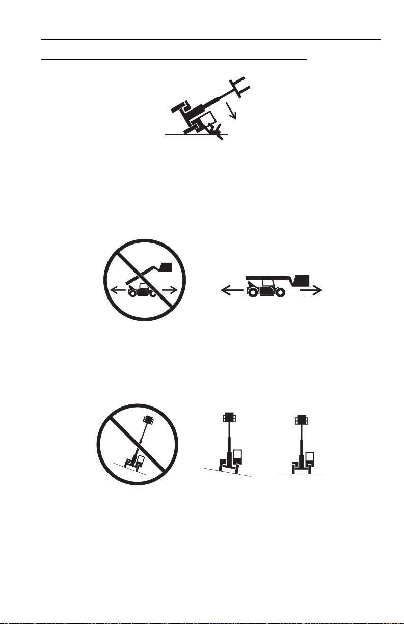
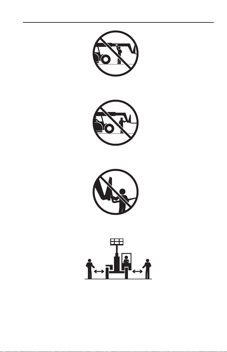
Tip Over Hazard
OW0050
• Never use an attachment without the appropriate JLG supplied capacity chart
installed on the telehandler.
• DO NOT exceed rated lift capacity.
• Be sure that the ground conditions are able to support the machine.
OW0060
• DO NOT drive with boom raised.
• When driving in high speed, use only front wheel steer (if steering modes are
selectable).
OW0080
• DO NOT raise boom unless frame is level (0 degrees).
1-331200192
Page 14
Section 1 - General Safety Practices
4 FT
(1,2 M)
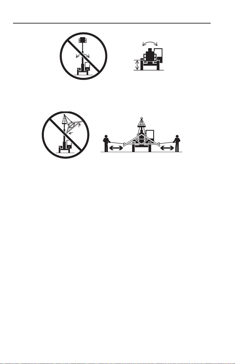
OW0100
• DO NOT level machine with boom/attachment above 4 ft (1,2 m).
OW0150
• Carry load as low as possible. Tether suspended loads to restrict movement.
• Understand how to properly use the capacity charts located in cab (see
page 5-3).
• Weight of all rigging (slings, etc.) must be included as part of load.
• Start, travel, turn and stop slowly to prevent load from swinging.
• Beware of wind. Wind can cause a suspended load to swing and cause
dangerous side loads - even with tag lines.
• DO NOT attempt to use telehandler frame-leveling to compensate for load swing.
• Keep heavy part of load closest to attachment.
• Never drag the load; lift vertically.
1-4 31200192
Page 15
Section 1 - General Safety Practices
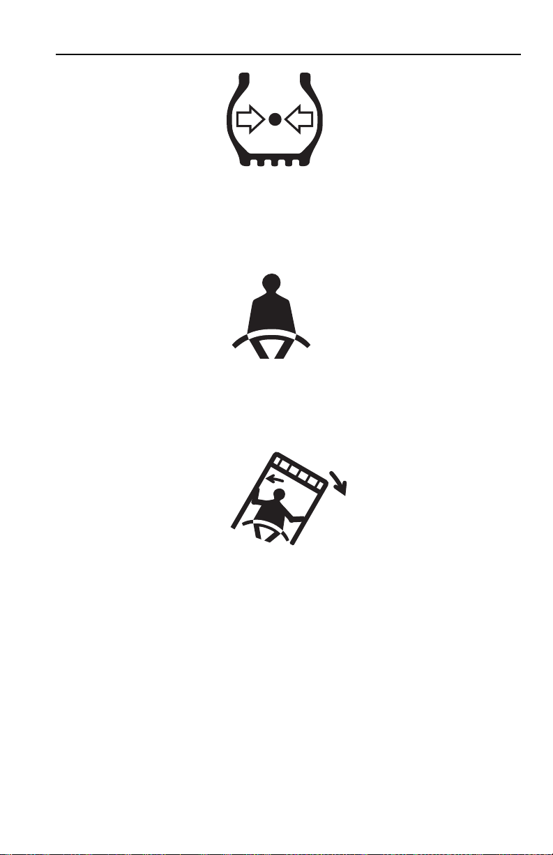
OH2291
• MAINTAIN proper tire pressure at all times. If proper tire pressures are not
maintained, this machine could tip over.
• Refer to manufacturer’s specifications for proper fill ratio and pressure
requirements for tires equipped with ballast.
OH20911
• Always wear the seat belt.
• Keep head, arms, hands, legs and all other body parts inside operator’s cab at all
times.
OH2221
If the telehandler starts to tip over:
• DO NOT JUMP
• BRACE YOURSELF and STAY WITH THE MACHINE
• KEEP YOUR SEAT BELT FASTENED
•HOLD ON FIRMLY
• LEAN AWAY FROM THE POINT OF IMPACT
Trying to escape from a tipping machine could result in death or serious injury.
1-531200192
Page 16

Section 1 - General Safety Practices
Travel Hazard
4-Wheel Steer Pivot Steer
• Steering characteristics differ between 4-Wheel Steer & Pivot Steer telehandlers
as shown above. Identify the telehandler you are operating & others on the
jobsite.
• Ensure that adequate clearance is provided between both rear tail swing and
front fork swing.
• Unlike a conventional 4-wheel steer telehandler the rear wheels of a pivot steer
telehandler turn a wider circle than the front wheels.
• Look out for and avoid other personnel, machinery and vehicles in the area. Use
a spotter if you DO NOT have a clear view.
• Before moving be sure of a clear path and sound horn.
• When driving, retract boom and keep boom/attachment as low as possible while
maintaining visibility of mirrors and maximum visibility of path of travel.
• Always look in the direction of travel.
• Always check boom clearances carefully before driving underneath overhead
obstructions. Position attachment/load to clear obstacles.
OW0120
1-6 31200192
Page 17

Section 1 - General Safety Practices
Load Falling Hazard
OW0130
• Never suspend load from forks or other parts of carriage.
• DO NOT burn or drill holes in fork(s).
• Forks must be centered under load and spaced apart as far as possible.
1-731200192
Page 18

Section 1 - General Safety Practices
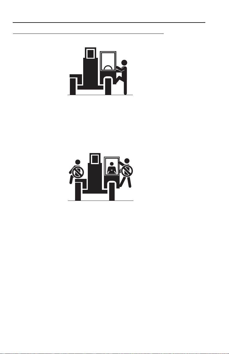
Lifting Personnel
OW0170
• When lifting personnel, USE ONLY a JLG approved personnel work platform,
with proper capacity chart displayed in the cab.
OW0190
• DO NOT drive machine from cab when personnel are in platform.
1-8 31200192
Page 19

Section 1 - General Safety Practices
Driving Hazards on Slopes
OW0200
To maintain sufficient traction and braking capabilities, travel on slopes as follows:
• When unloaded, the rear of the machine is the “heavy end.” Drive with forks
pointed downhill.
• When loaded, the front of the machine is the “heavy end.” Drive with the forks
pointed uphill.
• To avoid overspeeding the engine and drivetrain when driving down slopes,
downshift to a lower gear and use the service brake as necessary to maintain a
slow speed. DO NOT shift into neutral and coast downhill.
• Avoid excessively steep slopes or unstable surfaces. To avoid tip over DO NOT
drive across excessively steep slopes under any circumstances.
• Avoid turning on a slope. Never engage “inching” or shift to “Neutral” when going
downhill.
• DO NOT park on a slope.
1-931200192
Page 20
Section 1 - General Safety Practices
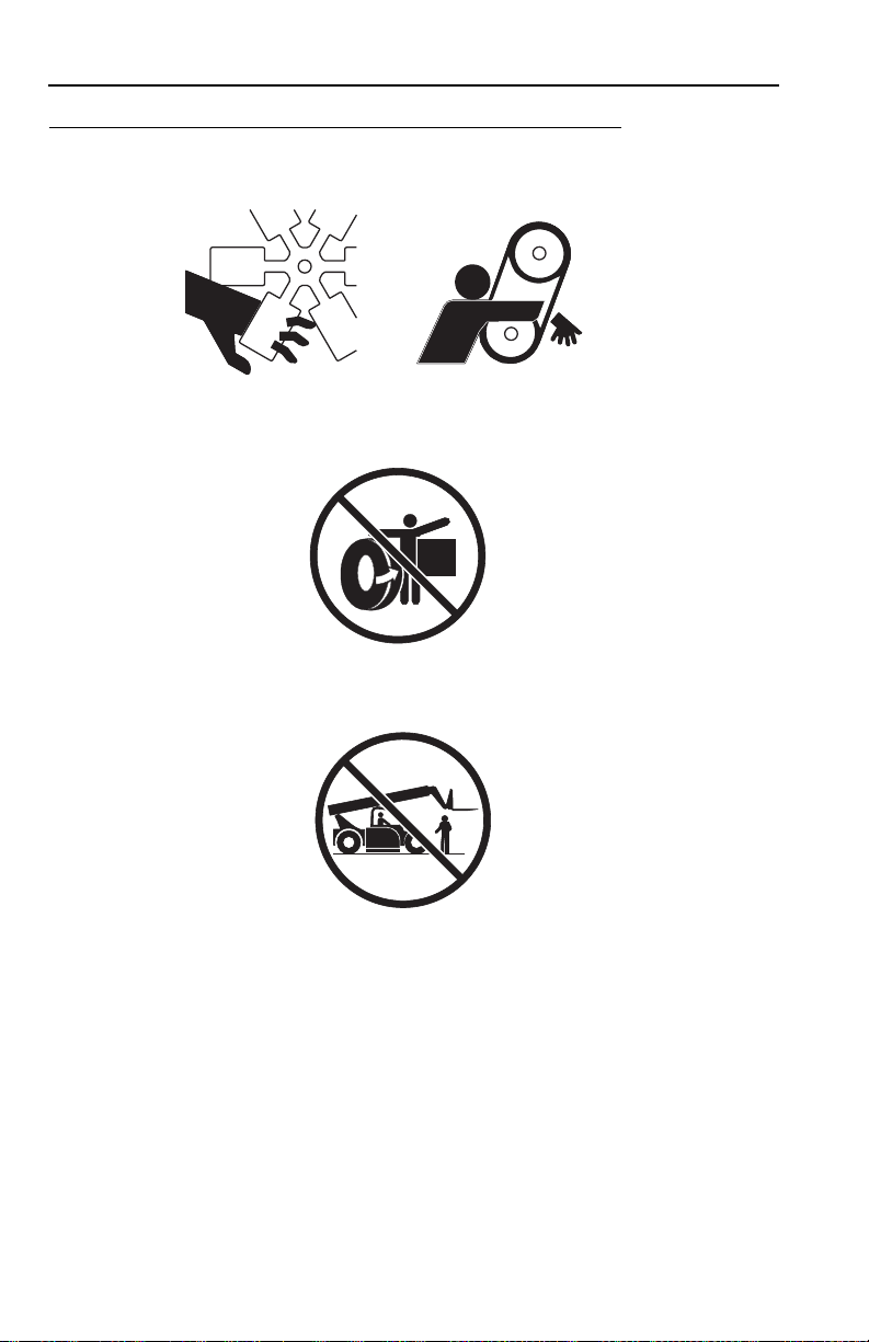
Pinch Points and Crush Hazards
Stay clear of pinch points and rotating parts on the telehandler.
• Stay clear of moving parts while engine is running.
OW0220
• Keep clear of steering tires and frame or other objects.
OW0210
OW0230
• Keep clear from under boom.
1-10 31200192
Page 21
Section 1 - General Safety Practices
OW0240
• Keep clear of boom holes.
OW0250
• Keep arms and hands clear of attachment tilt cylinder.
OW0260
• Keep hands and fingers clear of carriage and forks.
OW0960
• Keep others away while operating.
1-1131200192
Page 22
Section 1 - General Safety Practices
Fall Hazard
OW0280
• Enter using the proper hand holds and steps provided. Always maintain 3-point
contact when mounting or dismounting. Never grab control levers or steering
wheel when mounting or dismounting the machine.
• DO NOT get off the machine until the shutdown procedure on page 4-3 has been
performed.
OW0290
• DO NOT carry riders. Riders could fall off machine causing death or serious
injury.
1-12 31200192
Page 23

Section 1 - General Safety Practices
Chemical Hazards
Exhaust Fumes
• DO NOT operate machine in an enclosed area without proper ventilation.
• DO NOT operate the machine in hazardous environments unless approved for
that purpose by JLG and site owner. Sparks from the electrical system and the
engine exhaust can cause an explosion.
• If spark arrestors are required, ensure they are in place and in good working
order.
Flammable Fuel
OW0300
• DO NOT fill the fuel tank or service the fuel system near an open flame, sparks
or smoking materials. Engine fuel is flammable and can cause a fire and/or
explosion.
Hydraulic Fluid
OW0950
• DO NOT attempt to repair or tighten any hydraulic hoses or fittings while the
engine is running or when the hydraulic system is under pressure.
• Stop engine and relieve trapped pressure. Fluid in the hydraulic system is under
enough pressure that it can penetrate the skin.
• DO NOT use your hand to check for leaks. Use a piece of cardboard or paper to
search for leaks. Wear gloves to protect hands from spraying fluid.
1-1331200192
Page 24

Section 1 - General Safety Practices
This Page Intentionally Left Blank
1-14 31200192
Page 25
Section 2 - Pre-Operation and Inspection
SECTION 2 - PRE-OPERATION AND INSPECTION
2.1 PRE-OPERATION CHECK AND INSPECTION
Note: Complete all required maintenance before operating unit.
WARNING
FALL HAZARD. Use extreme caution when checking items beyond your normal
reach. Use an approved ladder. Failure to comply could result in death or serious
injury.
The pre-operation check & inspection, performed at beginning of each work shift or
at each change of operator, should include the following:
1. Cleanliness - Check all surfaces for leakage (oil, fuel or battery fluid) or foreign
objects. Report any leakage to the proper maintenance personnel.
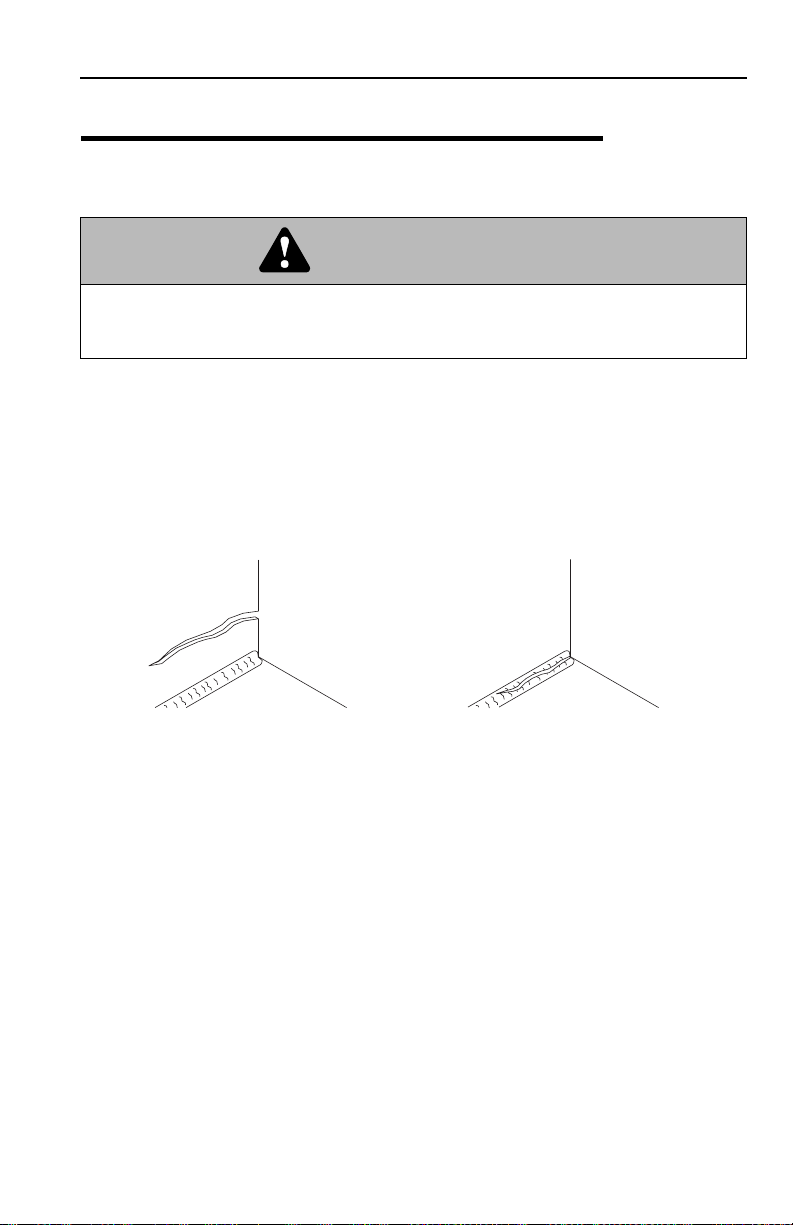
2. Structure - Inspect the machine structure for dents, damage, weld or parent
metal cracks or other discrepancies.
OAH1000
PARENT METAL CRACK WELD CRACK
3. Safety Decals - Ensure all safety decals are legible and in place. Clean or
replace as required. See page 2-3 for details.
4. Operation and Safety Manuals - Operation & Safety Manual and AEM Safety
Manual are located in cab manual holder.
5. Walk-Around Inspection - See page 2-6 for details.
6. Fluid Levels - Check fluids, including fuel, brake fluid, hydraulic oil, engine oil
and coolant. When adding fluids, refer to Section 7 - Lubrication and
Maintenance and Section 9 - Specifications to determine proper type and
intervals. Before removing filler caps or fill plugs, wipe all dirt and grease away
from the ports. If dirt enters these ports, it can severely reduce component life.
7. Attachments/Accessories - Ensure correct load charts are installed on the
telehandler. If provided, reference the Operation & Safety Manual of each
attachment or accessory installed for specific inspection, operation and
maintenance instructions.
2-131200192
Page 26

Section 2 - Pre-Operation and Inspection
8. Operational Check - Once the walk-around inspection is complete, perform a
warm-up and operational check (see page 2-8) of all systems in an area free of
overhead and ground level obstructions. See Section 3 - Controls and
Indicators for more specific operating instructions.
WARNING
If telehandler does not operate properly, immediately bring machine to a stop,
lower boom and attachment to ground and stop the engine. Determine cause and
correct before continued use.
2-2 31200192
Page 27
Section 2 - Pre-Operation and Inspection
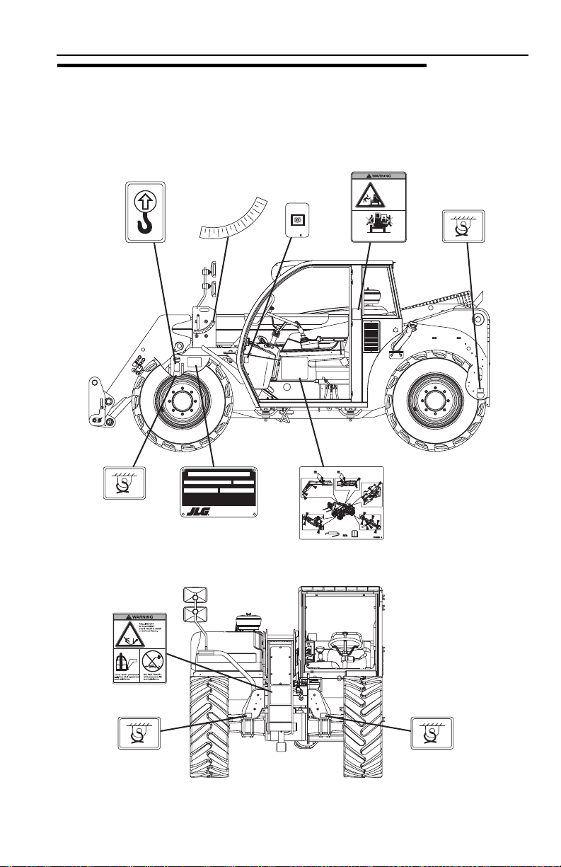
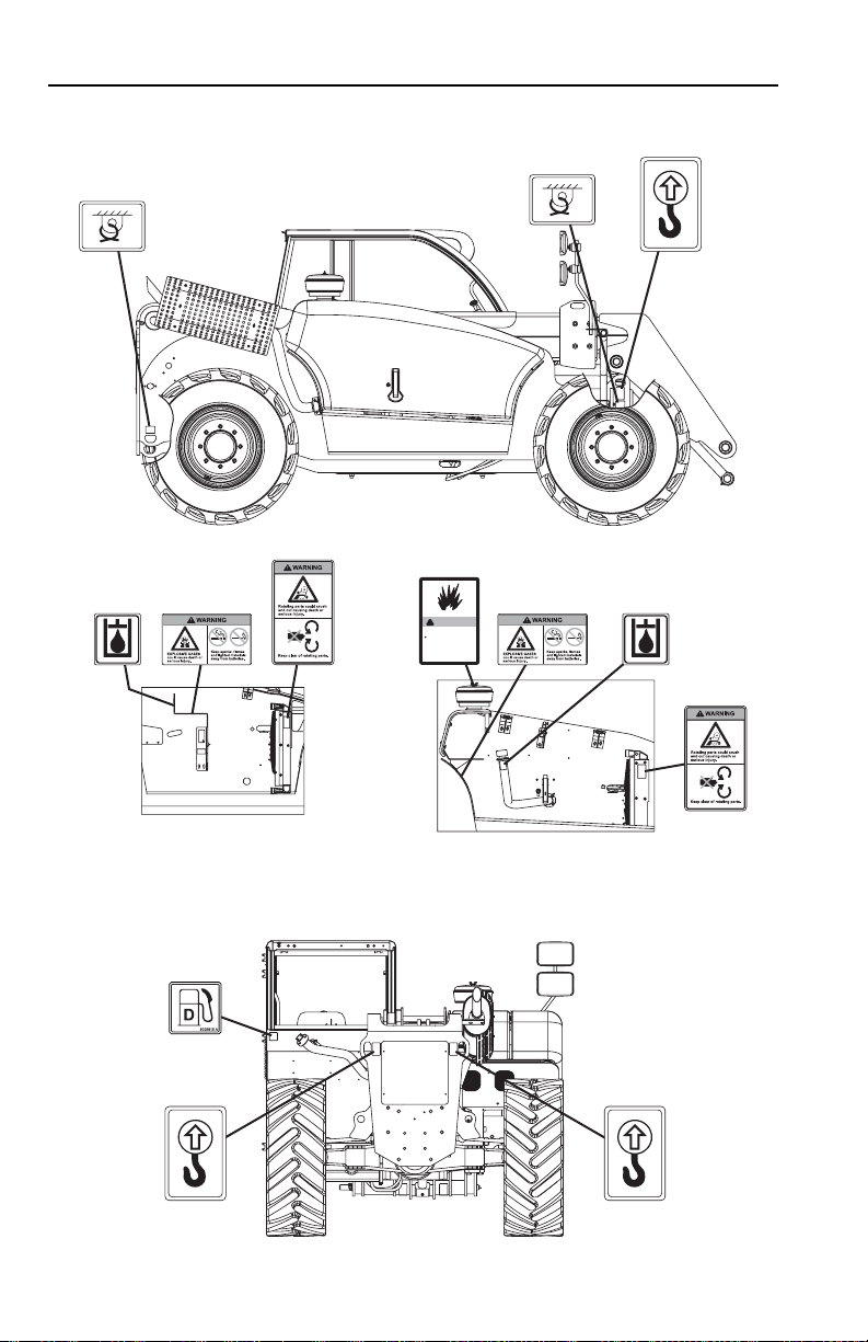
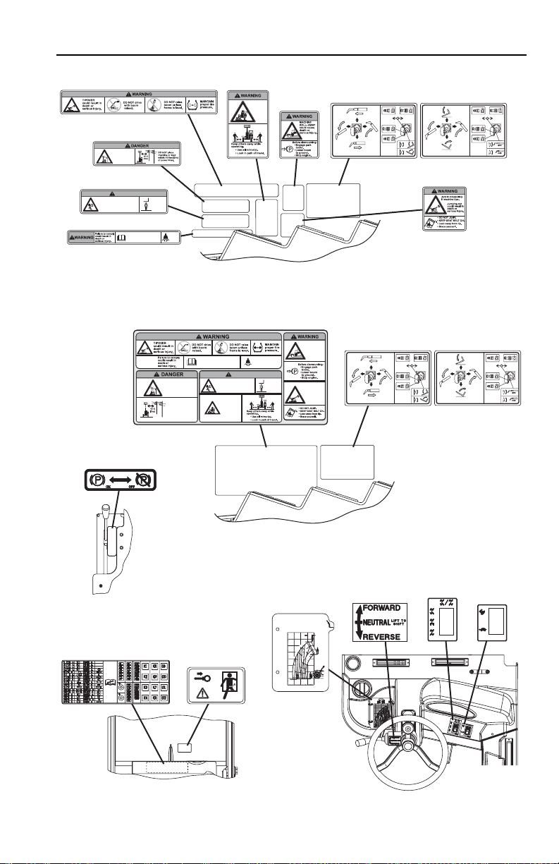
2.2 SAFETY DECALS
Ensure all DANGER, WARNING, CAUTION and instructional decals and proper
capacity charts are legible and in place. Clean and replace as required.
1701500
1701500
1702300
1702300
(S/N 116002234
& AFTER)
1705998
°
0
2
°
-1
0
0
1
°
0
°
60°
°
0
5
°
0
4
°
0
3
°
0
2
°
-1
0
0°
1
0
°
Model
SerialNumber
MaximumWeightWithout Attachments (lbs/kg)
°Referto load capacity chart for truck with attachment, and individual load ratings stamped
onforks,if equipped. Use lowest capacity of all ratings.
Asreleasedfrom factory this truck meets specifications in ASME B56.6-2002 Part III.
Oneormore of the following patents may apply to this truck; U.S. Nos. 4,954,041 6,349,969
5,639,1195,813,6975,230,399 5,052,532. Other patents pending.
MaximumCapacity(lbs/kg)
Manufacturedby
JLGManufacturing Europe BVBA
IndustrieterreinOudeBunders 1034, Breitwaterstraat 12
3630Maasmechelen- Belgium
R
YearOfManufacture
1706910
1706835
Riders
could
falloff
machine
No Riders
causing
deathor
serious
injury.
1702300
1706835A
1702300
2447967
OIL
60°
50°
40°
30°
1706910A
Dexron
ATF
2447 967
D
OAH0921
1706391
1706298A
1706298
1702300
1702300
(BEFORE
S/N 116002234)
1702300
1702300
(BEFORE
S/N 116002234)
OAH0802
2-331200192
Page 28
Section 2 - Pre-Operation and Inspection
1702300
1702300
(S/N 116002234
& AFTER)
1702300
1702300
1701500
1701500
1706301
1701504
1706297
A
7
9
2
6
0
1701504 A
7
1
VIEW OF ENGINE COMPARTMENT
WITH ENGINE REMOVED
(BEFORE S/N 116002380)
8009815
1704972
A
7
9
2
6
0
7
1
1701504
1701504 A
!
WARNING
EXPLOSION/FIREHAZARD
Donot use starting fluid.
Thisunit isequipped withan
airintake heater or glow plugs.
Failureto follow instructions could
1706301A
resultin death or serious injury.
1706297
1704972C
1706301
1706301A
VIEW OF ENGINE COMPARTMENT
WITH ENGINE REMOVED
(S/N 116002380 & AFTER)
1701500
1701500
1701500
1701500
OAH0811
2-4 31200192
Page 29
Section 2 - Pre-Operation and Inspection
1706306
1706299
CONTACTING
POWERLINES
willresult in death
orserious injury.
1706850
WARNING
CRUSHING HAZARD
Loweringboom or falling load could
causedeath or serious injury.
1706850
WARNING
CRUSHING HAZARD
1706303
Loweringboom or falling load could
causedeath or serious injury.
1706303
Operatormust be trained and
mustread and understand
allcapacity charts, operator
1706209
XXXXXXX
1706306
1706299
CONTACTING
POWERLINES
willresult in death
orserious injury.
Keepothers
awaywhile
operating.
Keepothers
awaywhile
operating.
Operatormust be trained and
1706850A
mustread and understand
allcapacity charts, operator
andsafety manuals.
andsafety manuals.
XXXXX
28'
24'
60°
C
20'
50°
s
40°
b
16'
l
s
0
b
0
l
6
0
5
s
30°
0
b
12'
l
6
6600 lbs
4
s
0
b
0
l
0
0
4
20°
s
0
8'
b
l
5
3
s
0
b
0
l
0
0
3
10°
0
4'
5
2
0°
0'
-4'
LOAD
CHARTS
1706304
RUN-OVER
HAZARD
1706767
couldcause
1706306A
1706299A
1706299A
1706850A
A
3
Fasten
0
3
seat
6
0
belt.
7
1
A
3
Fasten
0
3
VIEW OF DECALS LOCATED INSIDE CAB
seat
6
0
belt.
7
1
deathor
serious
injury.
1706304
1706306A
RUN-OVER
HAZARD
1706767
couldcause
deathor
serious
injury.
1706304A
1706304A
ON RIGHT HAND WINDOW
(BEFORE S/N 116002380)
1707078
Operatormust be trained and
mustread and understand
allcapacity charts, operator
andsafety manuals.
CONTACTING
POWERLINES
willresult in death
orserious injury.
DONOT place
machineor load
within10 feet (3m)
ofpower lines.
P/N 1234567
P/N 9876543
P/N 9876541
24
B
A
0'4'8'12'16'
WARNING
LOWERINGBOOM or
FALLINGLOAD
cancrush causing death
orserious injury.
RUN-OVER
HAZARD
c
ouldcause
deathor
serious
injury.
4017
14
13
12
11
50°
10
9
40°
EN 1459 B (1998)
8
7
30°
6
g
k
0
0
0
g
5
.
k
20°
1
0
g
0
k
5
.
0
4
1
0
5
g
k
3
0
5
7
10°
g
k
2
0
0
4
1
0°
0
8008746 B
m
8210
9
Fasten
seat
belt.
Keepothers
awaywhile
operating.
P/N 1170001
P/N 2340029
P/N 4802111
P/N 8008014
70°
G
2
0
00kg
60°
F
E
D
C
g
k
B
0
g
0
k
0
.
0
4
0
A
g
0
.
k
3
0
g
0
k
0
0
.
g
0
2
k
5
.
0
3
0
5
.
2
VIEW OF DECALS LOCATED INSIDE CAB
ON RIGHT HAND WINDOW
(S/N 1160002380 & AFTER)
MACHINE
ROLL-AWAY
couldcause
deathor
seriousinjury.
JUMPINGOFF
ofa tipping
machinecould
resultin
deathor
seriousinjury.
1707078A
A
7
6
7
6
0
7
1
(Standard)
1706944A
A
7
6
7
6
0
1706944A
7
1
1706944A
1706944
1706944
(Standard)
1706944
(Standard)
1706951
(Optional)
1706951A
1706851
1706951A
1706851
1706951A
9116-3028
1706951
(Optional)
1706851A
1706851A
1706951
(Optional)
VIEW OF PARK
BRAKE LEVER
1706463
1706463
VIEW OF REAR WINDOW
8005870
8005870
LOAD
CHARTS
XXXXX
28'
24
24'
60°
C
20'
50°
B
s
A
40°
b
16'
l
s
0
b
0
l
6
0
5
s
30°
0
b
12'
l
6
6600 lbs
4
s
0
b
0
l
0
0
4
20°
s
0
8'
b
l
5
3
s
0
b
0
l
0
0
3
10°
0
4'
5
2
0°
0'
8005870
-4'
XXXXXXX
0'4'8'12'16'
8005870
91163028
P/N 1234567
P/N 9876543
P/N 9876541
4017
14
13
12
11
50°
10
9
40°
EN 1459 B (1998)
8
7
30°
6
g
k
0
0
0
5
.
20°
1
g
k
0
4
0
5
g
k
3
0
5
7
10°
g
k
2
0
0
4
1
0°
0
8008746 B
m
8210
9
1706801
P/N 1170001
P/N 2340029
P/N 4802111
P/N 8008014
70°
G
2
0
0
0
60°
k
g
F
E
D
C
g
k
B
0
g
0
k
0
.
0
4
0
A
g
0
.
k
3
0
g
0
k
0
0
.
g
0
2
k
5
.
0
3
0
5
.
g
k
2
0
0
5
.
1
1706801A
1706209
1706859
1706859A
OAH0821
OAH0822
TOP VIEW OF DASH
2-531200192
Page 30
Section 2 - Pre-Operation and Inspection
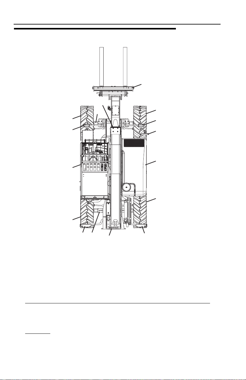
2.3 WALK-AROUND INSPECTION
13
1
2
3
4
5
6
47
Begin your walk-around inspection at item 1, as noted below. Continue to your right
(counterclockwise when viewed from top) checking each item in sequence.
INSPECTION NOTE: On all components, make sure there are no loose or missing
parts, that they are securely fastened and no visible leaks or excessive wear exists
in addition to any other criteria mentioned. Inspect all structural members including
attachment for cracks, excessive corrosion and other damage.
8
4
12
4
11
10
9
OAH0790
1. Boom Sections & Lift, Tilt, Extend/Retract, Compensating (Slave) Cylinders
• Check front, top, side & rear slider pads for adequate grease.
• Pivot pins secure; hydraulic hoses undamaged, not leaking.
2. Front Axle
undamaged, not leaking.
- Steer cylinders undamaged, not leaking; hydraulic hoses
-
2-6 31200192
Page 31

Section 2 - Pre-Operation and Inspection
3. Wheel/Tire Assembly - Properly inflated and secured; no loose or missing lug
nuts. Inspect for worn tread, cuts, tears or other discrepancies.
4. Worklights
(if equipped) - Clean, undamaged and work properly.
5. Cab & Electrical
• General appearance; no visible damage.
• Window glass undamaged and clean.
• Gauges, switches, joystick, foot controls, park brake & horn operational.
• Check seat belt for damage, replace belt if frayed or cut webbing, damaged
buckles or loose mounting hardware.
6. Wheel/Tire Assembly
nuts. Inspect for worn tread, cuts, tears or other discrepancies.
7. Rear Axle
hydraulic hoses undamaged, not leaking.
8. Main Control Valve
9. Wheel/Tire Assembly
nuts. Inspect for worn tread, cuts, tears or other discrepancies.
10. Engine Compartment
• Drive belts, check condition & replace as required.
• Air cleaner element condition indicator, check for clogged condition. Replace
element as required.
• Check and clean Pre-Cleaner as required.
• Battery cables tight, no visible damage or corrosion.
• Engine cover properly secured and latched.
11. Mirrors
- Clean and undamaged.
-
- Properly inflated and secured; no loose or missing lug
- Steer cylinders undamaged, not leaking; pivot pins secure;
- See Inspection Note.
- Properly inflated and secured; no loose or missing lug
-
12. Wheel/Tire Assembly
nuts. Inspect for worn tread, cuts, tears or other discrepancies.
13. Attachment
- Properly installed, see “Attachment Installation” on page 5-7.
- Properly inflated and secured; no loose or missing lug
2-731200192
Page 32

Section 2 - Pre-Operation and Inspection
2.4 WARM-UP AND OPERATIONAL CHECKS
Warm-Up Check
During warm-up period, check:
1. Heater, defroster and windshield wiper (if equipped).
2. Check all lighting systems (if equipped) for proper operation.
3. Voltmeter should show 13.5 to 14 volts.
4. Adjust mirror(s) for maximum visibility.
WARNING
CUT/CRUSH/BURN HAZARD. Keep engine cover closed while engine is
running. Failure to comply could result in death or serious injury.
Operational Check
When engine warms, perform an operational check:
1. Service brake and parking brake operation.
2. Forward and reverse travel.
3. Each gear.
4. Steering in both directions with engine at low idle (steering lock to lock will not
be reached). Check in each steering mode.
5. Horn and back-up alarm. Must be audible from inside operators cab with engine
running.
6. All boom and attachment functions - operate smoothly and correctly.
7. Perform any additional checks described in Section 8.
2-8 31200192
Page 33

Section 2 - Pre-Operation and Inspection
2.5 OPERATOR CAB
The telehandler is equipped with a standard open ROPS/FOPS cab. An optional
enclosed ROPS/FOPS cab is available.
WARNING
Never operate telehandler unless the overhead guard and cab structure are in
good condition. Any modification to this machine must be approved by JLG to
assure compliance with ROPS/FOPS certification for this cab/machine
configuration. If damaged, the CAB CANNOT BE REPAIRED. It must be
REPLACED.
2-931200192
Page 34

Section 2 - Pre-Operation and Inspection
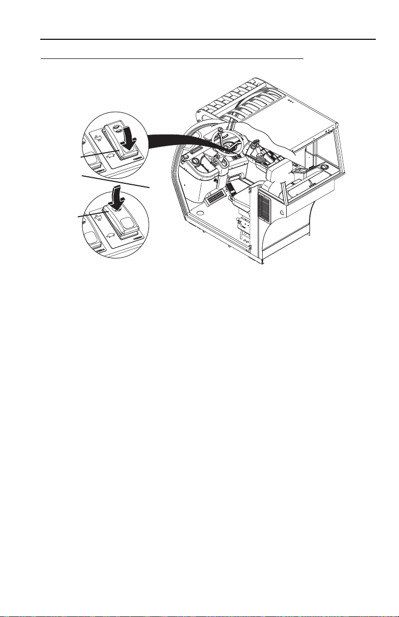
2.6 WINDOWS
Keep all windows and mirrors clean and unobstructed.
Cab Door Window (if equipped)
1
2
OZ0210
• During operation the window must either be latched open or closed.
• Open the cab door window (1) and secure it in the latch.
• Press the release button (2) inside the cab to unlatch the window.
Rear Window
4
3
OZ0220
• Lift lever (3) and push to open the rear window (4).
• Lift lever and pull to close.
2-10 31200192
Page 35

Section 3 - Controls and Indicators
SECTION 3 - CONTROLS AND INDICATORS
3.1 GENERAL
This section provides the necessary information needed to understand control
functions.
Note: The manufacturer has no direct control over machine application and
operation. The user and operator are responsible for conforming with good safety
practices.
3-131200192
Page 36

Section 3 - Controls and Indicators
3.2 CONTROLS
11
10
9
8
7
6
5
4
3
2
1
12
13
14
15
16
17
18
OAH0661
1. Parking Brake: See page 3-7 for details.
2. Accelerator Pedal
speed.
3. Steer Select Switch
and 2-wheel steer. See page 3-18 for details.
4. Service Brake Pedal
speed.
5. Ignition: Key activated. See page 3-6 for details.
6. Steering Column Adjuster: See page 3-11 for details.
7. Transmission Control Lever
8. Brake Fluid Reservoir
MAX marks. The sight gauge is on the left side of the reservoir.
: Pressing down the pedal increase engine and hydraulic
: Three positions: 4-wheel circle steer, 4-wheel crab steer
: The further the pedal is depressed, the slower the travel
: See page 3-8 for details.
: The brake fluid level should be between the MIN and
3-2 31200192
Page 37

Section 3 - Controls and Indicators
9. Steering Wheel: Turning the steering wheel to the left or right steers the
machine in the corresponding direction.
10. Level Indicator
of the telehandler.
11. Instrument Panel: See page 3-4 for details.
12. Accessory Control Lever (if equipped): See page 3-10 for details.
: Enables the operator to determine the left to right level condition
13. Gear Selection Switch
14. Joystick
15. Continuous Hydraulic Powered Attachment Operation Switch: Press switch for
continuous operation of hydraulic powered attachment. See Section
5 - Attachments for approved attachments and control instructions.
16. Bucket Mode Switch
attachment tilt function.
17. Control & Indicator Console: See page 3-16 for details.
18. Heater and Air Conditioner Controls (if equipped): See page 3-17 for details.
: See page 3-12 for details.
: See page 3-9 for details.
(if equipped): Press switch for increased reponse to
3-331200192
Page 38

Section 3 - Controls and Indicators
Instrument Panel
3
1
15
2
10
5
0
rpm x 100
20
25
30
4
5
6
7
8910111213141516
OAH0670
1. Fuel Gauge: Gauge for the diesel fuel tank.
2. Low Fuel Warning Indicator
: Illuminates when diesel fuel level is below 1/8 tank.
3. Engine RPM Indicator: Indicates engine speed in revolutions per minute (rpm).
4. Engine Coolant Temperature Gauge
5. Engine Coolant Temperature Warning Indicator
: Gauge for engine coolant temperature.
: Illuminates when coolant
temperature is too high.
6. Hourmeter
: Indicates total time of engine operation in hours and tenths of
hours. Hourmeter symbol is visible and flashes only when engine is running.
7. High beam Indicator
(if equipped): Illuminates while high beam lights are
activated.
8. Turn Signal Indicator (if equipped): Illuminates and flashes while turn signals
are activated in either direction or the hazard lights have been activated.
9. All Wheel Steering Mode Indicator
: Illuminates while activated: All wheels are
steering. The front wheels steer in the opposite direction from the rear wheels.
10. Crab Steer Mode Indicator
: Illuminates while activated: All wheels are steering
in the same direction.
11. Front Wheel Steer Mode Indicator: Illuminates while activated: The front wheels
are steering.
12. Park Brake Indicator
: Illuminates when park brake is activated (see page 3-7).
Park brake must be applied to start engine.
13. Hydraulic Return Filter Indicator
: Illuminates when filter requires maintenance.
3-4 31200192
Page 39

Section 3 - Controls and Indicators
14. Engine Pre-Heat Indicator: Illuminates with ignition key in position 1. Light goes
out when start temperature is reached. At temperatures below 32°F (0°C), do
not start until light goes out.
15. Engine Oil Pressure Indicator
engine immediately.
16. Battery Charge Indicator
briefly during starting. Illuminates during operation when battery is at low
charge.
: Illuminates when low oil pressure occurs. Stop
: Illuminates with the ignition key in position 1 and
CAUTION
EQUIPMENT DAMAGE. When a red light illuminates and a warning tone is
heard, immediately bring machine to a stop, lower boom and attachment to
ground and stop the engine. Determine cause and correct before continued use.
3-531200192
Page 40

Section 3 - Controls and Indicators
Ignition
0
I
II
III
OZ1110
•Position 0 - Engine off
•Position I- Voltage is available for all electrical functions. Engine preheat at
temperature below 32°F (0°C). Wait to start engine until preheat indicator light on
instrument panel goes out.
•Position II- Prohibits rotating key switch to position 3 in the event the engine does
not start. Rotate the key to position 0 then back to position 3 to re-engage the
starter.
•Position III- Engine start.
3-6 31200192
Page 41

Section 3 - Controls and Indicators
Park Brake
4
5
OAH0680
The Park Brake Lever (4) controls the application and release of the park brake.
• Pull back to apply.
• Lift detent ring (5) and push forward to release.
WARNING
MACHINE ROLL-AWAY HAZARD. Always move park brake lever to "ON"
position, lower boom to ground and stop engine before leaving cab. Machine
roll-away could cause death or serious injury.
WARNING
CRUSH HAZARD. Turning engine off applies the park brake. Applying park brake
or turning engine off while traveling will cause unit to stop abruptly and could
cause load loss, resulting in death or serious injury. Either may be used in an
emergency situation.
Parking Procedure
1. Using service brake, stop telehandler in an appropriate parking area.
2. Follow “Shut-Down Procedure” on page 4-3.
3-731200192
Page 42

Section 3 - Controls and Indicators
Transmission Control Lever
F
N
R
1
Transmission control lever (1) engages forward or reverse travel.
• Lift and push lever forward for forward travel; lift and pull lever rearward for
reverse travel. Move lever to centered position for ‘Neutral’.
• Forward or reverse travel can be selected while in any gear.
• When traveling in reverse, the back-up alarm will automatically sound.
• Drive in reverse and turn only at slow rates of speed.
• Do not increase engine speed with the transmission in forward or reverse and the
service brake depressed in an attempt to get quicker hydraulic performances.
This could cause unexpected machine movement.
OAH0690
WARNING
TIP OVER/CRUSH HAZARD. Bring telehandler to a complete stop before
shifting transmission control lever. A sudden change in direction of travel could
reduce stability and/or cause load to shift or fall. Failure to comply could result in
death or serious injury.
3-8 31200192
Page 43
Section 3 - Controls and Indicators
Gear Selection Switch
2
3
OAH0701
Gear selection switch controls the displacement of the hydrostatic transmission.
Select the appropriate gear for the task being performed.
• Use lower gear (2) when transporting a load.
• Use higher gear (3) only when driving unloaded for longer distances.
• Slow down prior to downshifting.
3-931200192
Page 44

Section 3 - Controls and Indicators
Accessory Control Lever (if equipped)
The accessory control lever (1) operates the turn signals, parking lights and
headlights.
2
7
5
1
4
6
3
OAH0710
Turn Signal
• Push the lever forward (2) to activate the left turn signal.
• Pull the lever back (3) to activate the right turn signal.
• The lever must be manually returned to the center position to deactivate either
turn signal. The lever will not cancel automatically after a turn.
Parking Lights & Headlights
• Turn the twist grip (4) of the lever counterclockwise to the first position (5) to turn
on the parking lights.
• Turn the twist grip to the second position (6) to turn on the headlights.
• Raise/lower the lever to switch between low beam and high beam.
• Turn the twist grip clockwise to the OFF position (7) to turn all lights off.
3-10 31200192
Page 45

Steering Column Adjuster
Section 3 - Controls and Indicators
8
•Follow “Shut-Down Procedure” on page 4-3.
• Turn the lever (8) counterclockwise to unlock.
• Place the steering column in the desired position.
• Turn to lever clockwise to lock steering column.
OAH0720
WARNING
TIP OVER/CRUSH HAZARD. Bring telehandler to a complete stop and shutdown
engine before adjusting steering column. A sudden change in direction of travel
could reduce stability and/or cause load to shift or fall. Failure to comply could
result in death or serious injury.
3-1131200192
Page 46

Section 3 - Controls and Indicators
Joystick
Refer to the joystick decal located inside the cab to verify control pattern. Ensure the
joystick decal matches the machine controls before operating.
Construction Pattern
1
4
The joystick (1) controls the boom and attachment functions.
Boom Functions
• Move the joystick back to lift boom; move joystick forward to lower boom. Move
joystick right to extend boom; move joystick left to retract boom.
• The speed of boom functions depends upon the amount of joystick travel in
corresponding direction. Increasing engine speed will also increase function
speed.
• For two simultaneous boom functions, move the joystick between quadrants. For
example; moving the joystick forward and to the left will lower and retract boom
simultaneously.
3
2
OAH0611
WARNING
TIP OVER/CRUSH HAZARD. Rapid, jerky operation of controls will cause rapid,
jerky movement of the load. Such movements could cause the load to shift or fall
or could cause the machine to tip over. Failure to comply could result in death or
serious injury.
3-12 31200192
Page 47

Section 3 - Controls and Indicators
Attachment Functions
• Attachment tilt is controlled by the rocker switch (2). Push the rocker switch up to
tilt attachment forward (down); push the rocker switch down to tilt attachment
back (up).
• Auxiliary Hydraulics (if equipped) buttons (3 & 4) control functions of attachments
that require hydraulic supply for operation. Buttons (4) can be used
simultaneously with normal boom attachment functions. Button (3) must be used
independently of boom lift/lower functions. See Section 5 - Attachments for
approved attachments and control instructions.
3-1331200192
Page 48

Section 3 - Controls and Indicators
Agricultural Pattern
1
4
The joystick (1) controls the boom and attachment functions.
Boom Functions
• Move the joystick back to lift boom; move joystick forward to lower boom. Extend/
retract is controlled by the rocker switch (2). Push the rocker switch up to extend
boom; push the rocker switch down to retract boom.
• The speed of boom functions depends upon the amount of joystick travel in
corresponding direction. Increasing engine speed will also increase function
speed.
• For two simultaneous functions, move the joystick between quadrants. For
example; moving the joystick forward and to the left will lower boom and tilt
attachment back (up) simultaneously.
3
2
OAH0621
WARNING
TIP OVER/CRUSH HAZARD. Rapid, jerky operation of controls will cause rapid,
jerky movement of the load. Such movements could cause the load to shift or fall
or could cause the machine to tip over. Failure to comply could result in death or
serious injury.
3-14 31200192
Page 49

Section 3 - Controls and Indicators
Attachment Functions
• Move joystick right to tilt attachment forward (down); move joystick left to tilt
attachment back (up).
• Auxiliary Hydraulics (if equipped) buttons (3 & 4) control functions of attachments
that require hydraulic supply for operation. Buttons (4) can be used
simultaneously with normal boom attachment functions. Button (3) must be used
independently of boom lift/lower functions. See Section 5 - Attachments for
approved attachments and control instructions.
3-1531200192
Page 50

Section 3 - Controls and Indicators
Control and Indicator Console
1
3
2
4
5
6
7
8
9
Controls and indicates the electrical accessories of the telehandler.
1. Hazard Switch (if equipped): On/Off switch.
2. Boom Work Light Switch
3. Front Work Light Switch
4. Rear Work Light Switch (if equipped): On/Off switch.
5. Rotating Beacon Switch
beacon on the cab roof. Power is supplied by a 12v receptacle at the left rear
part of the cab roof.
6. Windshield Wiper & Washer Switch
Press and hold to third position to turn on washer. Return switch to first position
to turn off wiper.
7. Horn Switch
8. Front/Rear Hydraulic Select Switch
position to activate rear hydraulics. Return switch to first position to activate
front auxiliary hydraulics.
9. Auxiliary Hydraulic Circuit/ Hydraulic Quick-Switch Switch
Press button to select the desired auxiliary hydraulic circuit. See Section
5 - Attachments for approved attachments and control instructions.
: Press and hold to sound horn.
(if equipped): On/Off switch.
(if equipped): On/Off switch.
(if equipped): Place the magnetic base of the rotating
(if equipped): Press switch to activate wiper.
(if equipped): Press switch to second
(if equipped):
OAH0730
3-16 31200192
Page 51

Section 3 - Controls and Indicators
Heater and Air Conditioner Controls (if equipped)
14
13
10. Fan Speed: 3-position rotary switch for heater and air conditioner.
11. Temperature Control: Adjustable rotary switch.
12. A/C Switch
13. Round Vent
14. Air Louver: Four individually adjustable air louvers.
: On/Off switch.
: Three individually adjustable round vents.
14
14
14
13
10
11
12
OAH0740
Heater
Turn the temperature control to the desired temperature and set the fan speed.
Adjust the air flow through the air louvers and round vents.
Air Conditioner
Turn on the air conditioner and set the fan speed. Adjust the air flow through the air
louvers and round vents.
Note: When the windows are misted over, run the air conditioner and heater at the
same time.
Defrosting
Direct the flow of air through the louvers and the left front round vent toward the
windshield. Close the other two round vents.
3-1731200192
Page 52

Section 3 - Controls and Indicators
3.3 STEER MODES
Stop the telehandler before changing steering modes. An indicator light on the
instrument panel will indicate the steering mode selected.
All-Wheel Steer
OAH0751
Front-Wheel Steer
OAH0761
Crab Steer
OAH0771
3-18 31200192
Page 53

Section 3 - Controls and Indicators
3.4 OPERATOR SEAT
Adjustments
Prior to starting the engine adjust seat for position and comfort as follows:
1. Turn the knob to adjust suspension to the appropriate weight setting.
2. Use knob to adjust backrest angle.
3. Always fasten seat belt during operation.
4. Lift handle to move seat fore and aft.
5. Lift latch to adjust cushion angle.
3-1931200192
Page 54

Section 3 - Controls and Indicators
Seat Belt
OH20912
Fasten seat belt as follows:
1. Grasp both free ends of the belt making certain that belt webbing is not twisted
or entangled.
2. With back straight in the seat, couple the retractable end (male end) of the belt
into the receptacle (buckle) end of the belt.
3. With belt buckle positioned as low on the body as possible, pull the retractable
end of the belt away from the buckle until it is tight across the lap.
4. To release belt latch, depress red button on the buckle and pull free end from
buckle.
3-20 31200192
Page 55

Section 3 - Controls and Indicators
3.5 BOOM ANGLE AND EXTENSION INDICATORS
2
1
0
7
°
0
6
°
0
5
°
0
4
°
0
3
°
0
-
°
2
2
°
0
0
-
°
°
1
1
0
°
0
OAH0650
• The boom angle indicator (1) is located on the left side of the boom. Use this
indicator to determine the boom angle when using the capacity chart (see “Use
of the Capacity Chart” on page 5-3).
• Boom extension indicators (2) are located on the left side of the boom. Use these
indicators to determine boom extension when using the capacity chart (see “Use
of the Capacity Chart” on page 5-3).
3-2131200192
Page 56

Section 3 - Controls and Indicators
This Page Intentionally Left Blank
3-22 31200192
Page 57

Section 4 - Operation
SECTION 4 - OPERATION
4.1 ENGINE
Starting the Engine
This machine can be operated under normal conditions in temperatures of 0°F to
104°F (-20°C to 40°C). Consult JLG for operation outside this range or under
abnormal conditions.
1. Make sure all controls are in “Neutral” and all electrical components (lights,
heater, defroster, etc.) are turned off. Set parking brake.
2. Turn ignition switch to position 1. If temperature is below 32°F (0°C), wait for
preheat light to go out.
3. Turn ignition switch to position III to engage starting motor. Release key
immediately when engine starts. If engine fails to start within 20 seconds,
release key and allow starting motor to cool for a few minutes before trying
again.
4. After engine starts, if oil pressure does not rise for more than ten seconds, the
engine oil pressure indicator will illuminate on instrument panel and buzzer will
sound. Stop engine and determine cause before restarting engine. Reference
engine manual for minimum pressure at operating temperature.
5. Warm up engine at approximately 1/2 throttle.
Note: Engine will not start unless transmission control lever is in “Neutral” and park
brake is applied.
WARNING
ENGINE EXPLOSION. Do not spray ether into air intake for cold weather
starting. Failure to comply could result in death or serious injury.
WARNING
UNEXPECTED MOVEMENT HAZARD. Always ensure that transmission control
lever is in neutral and the service brake is applied before releasing park brake.
Releasing park brake in either forward or reverse could cause the machine to
move abruptly, causing an accident resulting in death or serious injury.
4-131200192
Page 58

Section 4 - Operation
Battery Boosted Starting
OW0530
If battery-boost starting (jump-start) is necessary, proceed as follows:
• Never allow vehicles to touch.
• Connect the positive (+) jumper cable to positive (+) post of discharged battery.
• Connect the opposite end of positive (+) jumper cable to positive (+) post of
booster battery.
• Connect the negative (-) jumper cable to negative (-) post on booster battery.
• Connect opposite end of negative (-) jumper cable to ground point on machine
away from discharged battery.
• Follow standard starting procedures.
• Remove cables in reverse order after machine has started.
WARNING
BATTERY EXPLOSION HAZARD. Never jump start or charge a frozen battery
as it could explode. Keep sparks, flames and lighted smoking materials away
from the battery. Lead acid batteries generate explosive gases when charging.
Wear safety glasses. Failure to comply could result in death or serious injury.
4-2 31200192
Page 59

Section 4 - Operation
Normal Engine Operation
• Observe instrument panel frequently to be sure all engine systems are
functioning properly.
• Be alert for unusual noises or vibration. When an unusual condition is
noticed, park machine in safe position and perform shut-down procedure. See
Shut-Down Procedure. Report condition to your supervisor or maintenance
personnel.
• Avoid prolonged idling. If the engine is not being used, turn it off.
Shut-Down Procedure
When parking the telehandler, park in a safe location on flat level ground and away
from other equipment and/or traffic lanes.
1. Apply the park brake.
2. Shift the transmission to “Neutral.”
3. Lower forks or attachment to the ground.
4. Operate engine at low idle for 3 to 5 minutes. DO NOT over rev engine.
5. Shut off engine and remove ignition key.
6. Exit telehandler properly
7. Block wheels (if necessary).
4-331200192
Page 60

Section 4 - Operation
4.2 OPERATING WITH A LOAD
Lift Load Safely
• You must know the weight and load center of every load you lift. If you are not
sure of the weight and load center, check with your supervisor or with the
supplier of the material.
WARNING
TIP OVER HAZARD. Exceeding lift capacity of the telehandler could damage the
equipment and/or cause tip over resulting in death or serious injury.
• Know the rated load capacities (see Section 5) of the telehandler to determine
the operating range in which you can safely lift, transport and place a load.
Before Picking Up a Load
• Note the conditions of the terrain. Adjust travel speed and reduce amount of load
if conditions warrant.
• Avoid lifting double-tiered loads.
• Make sure load is clear of any adjacent obstacles.
• Adjust spacing of forks so they engage the pallet or load at maximum width. See
“Adjusting/Moving Forks” on page 5-11.
• Approach load slowly and squarely with fork tips straight and level. NEVER
attempt to lift a load with just one fork.
• NEVER operate telehandler without a proper and legible Capacity Chart in the
operator’s cab for the telehandler/attachment combination you are using.
4-4 31200192
Page 61

Section 4 - Operation
Transporting the Load
OW0540
After engaging the load and resting it against the backrest, tilt the load back to
position it for travel. Travel in accordance with the requirements set forth in Section
1 - General Safety Practices and Section 5 - Attachments.
Leveling Procedure
1. Position machine in best location to lift or place load.
2. Apply parking brake and move transmission control lever to NEUTRAL.
3. Move boom/attachment to 4 ft (1,2 m) off ground.
4. Observe level indicator to determine whether machine must be leveled prior to
lifting load.
Important things to remember:
• Never raise the boom/attachment more than 4 ft (1,2 m) above ground unless
telehandler is level.
• The combination of side tilt and load could cause the telehandler to tip over.
4-531200192
Page 62

Section 4 - Operation
Placing the Load
Before placing any load be sure that:
• The landing point can safely support the weight of the load.
• The landing point is level; front to back and side to side.
• Use the capacity chart to determine safe boom extension range. See “Use of the
Capacity Chart” on page 5-3.
• Align forks at the level load is to be placed, then extend boom slowly until load is
just above area where it is to be placed.
• Lower the boom until the load rests in position and the forks are free to retract.
Disengaging the Load
Once the load has been placed safely at the landing point, proceed as follows:
1. With the forks free from the weight of the load, the boom can be retracted
and/or the telehandler can be backed away from under the load if surface will
not change level condition of telehandler.
2. Lower the carriage.
3. The telehandler can now be driven from the landing location to continue work.
4-6 31200192
Page 63

Section 4 - Operation
4.3 LOADING AND SECURING FOR TRANSPORT
°
0
6
°
0
5
40°
°
0
3
°
0
2
°
0
1
1
0
°
0°
1702300
1701500
1702300
OAH0831
1701500
Tiedown
1. Using a spotter, load the telehandler with boom as low as possible.
2. Once loaded, apply parking brake and lower boom until boom or attachment is
resting on deck. Move all controls to “Neutral,” stop engine and remove ignition
key.
3. Secure machine to deck by passing chains through the designated tie down
points as shown in the figure.
4. Do not tie down front of boom.
Note: The user assumes all responsibility for choosing the proper method of
transportation and tie-down devices, making sure the equipment used is capable of
supporting the weight of the vehicle being transported and that all manufacturer’s
instructions and warnings, regulations and safety rules of their employer, the
Department of Transportation and/or any other state or federal laws are followed.
WARNING
TELEHANDLER SLIDE HAZARD. Before loading telehandler for transport,
make sure deck, ramps and telehandler wheels are free of mud, snow and ice.
Failure to do so could cause telehandler to slide, resulting in an accident causing
death or serious injury.
4-731200192
Page 64

Section 4 - Operation
Lifting
• When lifting machine, it is very important that the lifting device and equipment is
attached only to designated lifting points. If machine is not equipped with lifting
lugs contact JLG Product Safety for information.
• Make adjustments to the lifting device and equipment to ensure the machine will
be level when elevated. The machine must remain level at all times while being
lifted.
• Ensure that the lifting device and equipment is adequately rated and suitable for
the intended purpose. See Section 9 - Specifications for machine weight.
• Remove all loose items from machine prior to lifting.
• Lift machine with smooth, even motion. Set machine down gently. Avoid quick or
sudden motions that could cause shock loads to machine and/or lifting devices.
4-8 31200192
Page 65

Section 5 - Attachments
SECTION 5 - ATTACHMENTS
5.1 APPROVED ATTACHMENTS
To determine if an attachment is approved for use on the specific telehandler you are
using, perform the following prior to installation.
• The attachment model/option number on the attachment identification plate must
match the attachment number on a capacity chart located in the operator cab.
• The fork model/option number stamped on the side of the forks must match the
fork number on a capacity chart located in the operator cab.
• The model on the capacity chart must match the model telehandler being used.
• The load center of the fork (if equipped) must match the load center as indicated
on the capacity chart.
• Hydraulically powered attachments must only be used on machines equipped
with auxiliary hydraulics.
If any of the above conditions are not met, do not use the attachment. The
telehandler may not be equipped with the proper capacity chart or the attachment
may not be approved for the model telehandler being used. Contact JLG or your
local distributor for further information.
5.2 UNAPPROVED ATTACHMENTS
Do not use unapproved attachments for the following reasons:
• JLG cannot establish range and capacity limitations for “will fit,” homemade,
altered, or other non-approved attachments.
• An overextended or overloaded telehandler can tip over with little or no warning
and cause serious injury or death to the operator and/or those working nearby.
• JLG cannot assure the ability of a non-approved attachment to perform its
intended function safely.
WARNING
Use only approved attachments. Attachments which have not been approved for
use with your telehandler could cause machine damage or an accident resulting
in death or serious injury.
5-131200192
Page 66

Section 5 - Attachments
5.3 TELEHANDLER/ATTACHMENT/FORK CAPACITY
3
1
2
OZ0810
Prior to installing the attachment verify it is approved and the telehandler is equipped
with the proper capacity chart. See “Approved Attachments” on page 5-1.
To determine the maximum capacity of the telehandler and attachment, use the
smallest of the following capacities:
• Capacity stamped on the attachment identification plate (1).
• Fork capacities and load centers are stamped on the side of each fork (2)
(if equipped). This rating specifies the maximum load capacity that the individual
fork can safely carry at the maximum load center (3). Total attachment capacity is
multiplied by the number of forks on the attachment (if equipped), up to the
maximum capacity of the attachment.
• Maximum capacity as indicated on the proper capacity chart. See “Approved
Attachments” on page 5-1.
• When the load rating of the telehandler differs from the capacity of the forks or
attachment, the lower value becomes the overall load capacity.
Use the proper capacity chart to determine maximum capacity at various machine
configurations. Lifting and placing a load may require use of more than one capacity
chart based on machine configuration.
Other than block forks, all forks should be used in matched pairs, block forks used in
matched sets.
WARNING
Never use an attachment without the appropriate JLG supplied capacity chart
installed on the telehandler. Failure to install the proper JLG supplied capacity
chart could cause an accident resulting in death or serious injury.
5-2 31200192
Page 67

Section 5 - Attachments
5.4 USE OF THE CAPACITY CHART
To properly use the capacity chart (see page 5-4), the operator must first determine
and/or have the following:
1. A JLG approved attachment. See “Approved Attachments” on page 5-1.
2. The proper Capacity Chart.
3. Weight of the load being lifted.
4. Load placement information:
a. HEIGHT where the load is to be placed.
b. DISTANCE from the front tires of the telehandler where the load is to be
placed.
5. On the Capacity Chart, find the line for the height and follow it over to the
distance.
6. The number in the load zone where the two cross is the maximum capacity for
this lift. If the two cross at a division between zones, the smaller number must
be used.
The number in the load zone must be equal to or greater than the weight of the load
to be lifted. Determine the limits of the load zone on the Capacity Chart and keep
within these limits.
Capacity Indicator Locations
Attachment
Identification
Plate
Fork Part
Number and
Capacity Stamp
Boom Extension
Indicator
Boom Angle
Indicator
0
7
°
0
6
°
0
5
°
0
4
°
0
3
°
0
-
°
2
2
°
0
0
-
°
°
1
1
0
°
0
OAH0291
5-331200192
Page 68

Section 5 - Attachments
Sample Capacity Chart
This Capacity Chart may be
used with this model ONLY.
The model of your
telehandler is indicated on
the boom or chassis.
Model XXXX is used for
demonstration purposes only.
28'
24'
20'
16'
XXXXX
60°
50°
40°
These numbers must match the
model/option number stamped
on the attachment ID Plate and
on the forks being used.
P/N 1234567
P/N 9876543
P/N 9876541
24
C
B
A
Boom Extension
Indicator (arc)
4000 lbs
3500 lbs
5600 lbs
4600 lbs
6600 lbs
0'4'8'12'16'
OAH0950
Load zones indicate
the maximum weight
that may be safely lifted.
Boom Angle
XXXXXXX
12'
30°
20°
8'
3000 lbs
10°
4'
0'
-4'
2500 lbs
0°
Note: This is a sample capacity chart only! DO NOT use this chart, use the one
located in your operator cab.
WARNING
TIP OVER HAZARD. All loads shown on rated capacity chart are based on
machine being on firm ground with frame level (see page 4-5); the forks being
positioned evenly on carriage; the load being centered on forks; proper size tires
being properly inflated; and the telehandler being in good operating condition.
Failure to comply could result in death or serious injury.
5-4 31200192
Page 69

Section 5 - Attachments
To identify the proper capacity chart on telehandlers equipped with outriggers and/or
transfer carriage, refer to the following icons which may be located on the capacity
chart.
• Use when lifting a load with outriggers up.
OW0930
• Use when lifting a load with outriggers down.
OW0940
80"
1"
• Use for any forward movement (1 to 80 in) of the transfer
carriage.
OW0910
0"
• Use for no forward movement (0 in) of the transfer carriage.
Fully retracted position only.
OW0920
5-531200192
Page 70

Section 5 - Attachments
Example
A contractor owns a model xxxxx telehandler with a fork carriage. He knows this
attachment may be used with his model since:
• The attachment and fork model/option numbers match the attachment and fork
numbers on the capacity chart.
• The capacity chart is clearly marked for model xxxx and corresponds with
machine configuration being used.
Below are examples with various conditions the contractor may encounter and
whether or not the load may be lifted.
Load Weight Distance Height OK to Lift
1 4,250 lb (1928 kg) 6.5 ft (2,0 m) 18.5 ft (5,6 m) Yes
2 3,400 lb (1542 kg) 10 ft (3,0 m) 9.5 ft (2,9 m) NO
3 6,450 lb (2926 kg) 2 ft (0,6 m) 15 ft (4,6 m) Yes
4 6,100 lb (2767 kg) 6 ft (1,8 m) 6 ft (1,8 m) NO
P/N 1234567
XXXXX
P/N 9876543
P/N 9876541
Example 1
Example 2
XXXXXXX
28'
24'
20'
16'
12'
8'
4'
0'
-4'
40°
30°
20°
10°
2500 lbs
0°
60°
50°
5600 lbs
4600 lbs
4000 lbs
3500 lbs
3000 lbs
C
6600 lbs
24
B
A
Example 3
Example 4
0'4'8'12'16'
OAH0960
Note: This is a sample capacity chart only! DO NOT use this chart, use the one
located in your operator cab.
5-6 31200192
Page 71
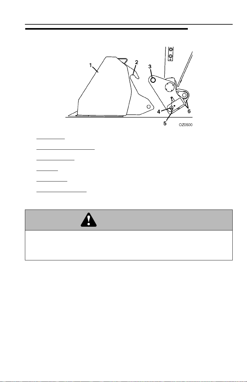
5.5 ATTACHMENT INSTALLATION
1. Attachment
2. Attachment Pin Recess
Section 5 - Attachments
3. Attachment Pin
4. Lock Pin
5. Retainer Pin (mechanical quick-switch only)
6. Quick-Switch device
(attachment tilt control in cab, see page 3-12 for details)
WARNING
CRUSH HAZARD. Always be certain that carriage or attachment is properly
positioned on boom and is secured by lock pin and retainer pin. Failure to ensure
proper installation could permit carriage/attachment/load to disengage causing
death or serious injury.
5-731200192
Page 72

Section 5 - Attachments
Mechanical Quick-Switch Device
This installation procedure is designed for one-person operation.
1. Retract quick-switch device to provide clearance.
Check to be sure lock pin and retainer pin is out.
2. Align attachment pin with recess in attachment.
Raise boom slightly to engage attachment pin in
recess.
3. Engage quick-switch device.
4. Shut off engine. Exit cab and insert lock pin and
secure with retainer pin.
5. If attachment is equipped, connect auxiliary hydraulic hoses. See “Hydraulic
Operated Attachment” on page 5-10.
5-8 31200192
Page 73

Section 5 - Attachments
Hydraulic Quick-Switch Device
This installation procedure is designed for one-person operation.
1. Retract quick-switch device to provide clearance.
Check to be sure lock pin is disengaged.
2. Align attachment pin with recess in attachment.
Raise boom slightly to engage attachment pin in
recess.
3. Engage quick-switch device.
4. Press the button (1) and at the same time
2
move the joystick (2) to engage or (3) to
disengage the quick-switch device.
1
3
OZ0610
5. Raise boom to eye level and visually check
that the quick-switch pin protrudes through
the hole. If the pin does not protrude
through the hole, place the attachment on
the ground and return to step 2.
ENGAGED DISENGAGED
OZ0900
6. If attachment is equipped, connect auxiliary hydraulic hoses. See “Hydraulic
Operated Attachment” on page 5-10.
5-931200192
Page 74

Section 5 - Attachments
Hydraulic Operated Attachment
1
3
4
2
OAH0640
OAH0940
1. Install attachment (see page 5-8 or 5-9).
2. Lower attachment to ground and set parking brake.
3. Quickly depress and release button (3) to relieve pressure at the male auxiliary
fitting.
4. Connect to the male auxiliary fitting (1).
5. Quickly depress and release button (4) to relieve pressure at the female
auxiliary fitting.
6. Connect to the female auxiliary fitting (1).
5-10 31200192
Page 75

Section 5 - Attachments
5.6 ADJUSTING/MOVING FORKS
Carriages may have different locations where forks can be positioned. Two different
methods can be used for repositioning, depending upon the carriage structure.
Note: Apply a light coating of appropriate lubricant to ease sliding of forks or fork
bar.
To slide forks:
1. Ensure attachment is properly installed. See “Attachment Installation” on
page 5-7.
2. Elevate attachment to approximately 5 ft (1,5 m) and tilt carriage forward until
fork heel is free from attachment.
3. Stand at the side of the carriage. To slide fork toward the center of the carriage,
push the fork near the fork eye. To slide fork toward the edge of the carriage,
pull the fork near the fork eye. To avoid pinching, do not place fingers or thumb
between the fork and carriage structure.
If removing fork bar is necessary:
1. Rest forks on ground.
2. Remove fork bar.
3. Reposition forks.
4. Reinstall the fork bar and fork bar retaining mechanism(s).
5.7 ATTACHMENT OPERATION
• Capacities and range limits for the telehandler change depending on the
attachment in use.
• Separate attachment instructions must be kept in manual holder in cab with this
Operation & Safety Manual. An additional copy must be kept with the attachment
if it is equipped with a manual holder.
• Operations described within this section reference construction joystick pattern,
see page 3-12. Refer to page 3-14 if equipped with agricultural joystick pattern.
CAUTION
EQUIPMENT DAMAGE. Some attachments may contact the front tires or
machine structure when the boom is retracted and the attachment is rotated.
Machine or attachment damage may occur from contact.
5-1131200192
Page 76

Section 5 - Attachments
Carriage w/Forks
Description P/N
Carriage..........................................................................1170028
Forks, 2x4.7 in ................................................................2340040
OZ0770
Use Carriage Attachment Capacity Chart
To determine maximum capacity, refer to “Telehandler/Attachment/Fork Capacity” on
page 5-2.
Forks, 2x3.9 in ................................................................2340041
1
2
OAH0870
The joystick (1) controls movement of the boom.
The rocker switch (2) located on the boom joystick controls carriage tilt.
• Push rocker switch down to tilt up.
• Push rocker switch up to tilt down.
Installation Procedure:
• Refer to “Attachment Installation” on page 5-7.
5-12 31200192
Page 77

Section 5 - Attachments
Truss Boom
Description P/N
Truss Boom, 11.8 ft - 1433 lb..........................................0240110
OZ0780
Use Truss Boom Attachment Capacity Chart
To determine maximum capacity, refer to “Telehandler/Attachment/Fork Capacity” on
page 5-2.
Suspend loads in accordance with requirements set forth in Section
1 - General Safety Practices.
1
2
The joystick (1) controls movement of the boom.
The rocker switch (2) located on the boom joystick controls truss boom tilt.
• Push rocker switch down to tilt up.
• Push rocker switch up to tilt down.
Installation Procedure:
• Refer to “Attachment Installation” on page 5-7.
OAH0880
5-1331200192
Page 78

Section 5 - Attachments
Side Shift Carriage
Description P/N
Side Shift Carriage ......................................................... 1170002
Forks, 1.7x4.9 in ............................................................. 2340029
OZ0800
Use Side Shift Carriage Attachment Capacity Chart
To determine maximum capacity, refer to “Telehandler/Attachment/Fork Capacity” on
page 5-2.
Forks, 2.0x3.9 in ............................................................. 2340030
Forks Cubing, 2.0x2.0............................................... 1001097922
1
2
OAH0870
The joystick (1) controls movement of the boom.
The rocker switch (2) located on the boom joystick controls carriage tilt.
• Push rocker switch down to tilt up.
• Push rocker switch up to tilt down.
5-14 31200192
Page 79

Section 5 - Attachments
7
6
3
To Side Shift:
• Use the button (3) to select the auxiliary hydraulic circuit.
• Press joystick button (4) to shift forks right or press joystick button (5) to shift
forks left.
OR
• While pressing and holding the joystick button (6), move the joystick forward (7)
to shift forks right or move the joystick back (8) to shift forks left.
Installation Procedure:
• Refer to “Attachment Installation” on page 5-7.
4
5
8
OAH0970
WARNING
CRUSH HAZARD. Do not use side shift to push or pull objects or load. Failure to
comply could cause object or load to fall resulting in death or serious injury.
5-1531200192
Page 80

Section 5 - Attachments
Side Tilt Carriage
Description P/N
Side Tilt Carriage............................................................ 1170046
Forks, 2x4.7 in ................................................................2340040
OZ0800
Use Side Tilt Carriage Attachment Capacity Chart
To determine maximum capacity, refer to “Telehandler/Attachment/Fork Capacity” on
page 5-2.
Forks, 2x3.9 in ................................................................2340041
1
2
OAH0870
The joystick (1) controls movement of the boom.
The rocker switch (2) located on the boom joystick controls carriage tilt.
• Push rocker switch down to tilt up.
• Push rocker switch up to tilt down.
5-16 31200192
Page 81

Section 5 - Attachments
7
6
3
To Side Tilt:
• Use the button (3) to select the auxiliary hydraulic circuit.
• Press joystick button (4) to side tilt carriage right or press joystick button (5) to
side tilt carriage left.
OR
• While pressing and holding the joystick button (6), move the joystick forward (7)
to side tilt carriage right or move the joystick back (8) to side tilt carriage left.
Installation Procedure:
• Refer to “Attachment Installation” on page 5-7.
4
5
8
OAH1010
WARNING
CRUSH HAZARD. Do not use side shift to push or pull objects or load. Failure to
comply could cause object or load to fall resulting in death or serious injury.
Operation:
• Approach load with forks centered on load and stop telehandler.
• Level telehandler before side tilting carriage to engage load.
• Side tilt carriage to left or right to align forks with load and engage load.
• Raise load slightly and then level carriage side to side.
• Travel in accordance with requirements set forth in Section 1 - General Safety
Practices.
5-1731200192
Page 82

Section 5 - Attachments
Bucket
Description P/N
Bucket, 4 in 1 - 0.78 yd3................................................. 0930006
Bucket, 4 in 1 - 1.3 yd
Bucket, 2.35 yd
OZ0730
Bucket, 1.96 yd3............................................................. 0930009
Bucket, 1.18 yd
Bucket, 1.05 yd
Use Appropriate Bucket Capacity Chart
To determine maximum capacity, refer to “Telehandler/Attachment/Fork Capacity” on
page 5-2.
3
3
3
3
................................................... 0930003
............................................................. 0930016
............................................................. 0930015
............................................................. 0930008
1
2
OAH0890
The joystick (1) controls movement of the boom.
The rocker switch (2) located on the boom joystick controls bucket tilt.
• Push rocker switch down to tilt up.
• Push rocker switch up to tilt down.
Installation Procedure:
• Refer to “Attachment Installation” on page 5-7.
5-18 31200192
Page 83

Section 5 - Attachments
Equipment Damage Precautions
• Drive into stockpile smoothly with boom fully retracted to load bucket. Loading
bucket with boom extended could damage boom. Do not corner-load bucket.
• Distribute material evenly within the bucket. Bucket capacity charts are for evenly
distributed loads only.
• Do not use bucket as a lever to pry material. Excessive prying forces could
damage bucket.
• Do not use bucket for "back dragging". This could cause severe damage to quick
switch.
Operation:
• Raise or lower boom to appropriate height for loading material from stockpile.
• Align telehandler with face of stockpile and drive slowly and smoothly into pile to
load bucket.
• Tilt bucket up far enough to retain load and back away from pile.
• Travel in accordance with requirements set forth in Section 1 - General Safety
Practices.
• Tilt bucket down to dump load.
5-1931200192
Page 84

Section 5 - Attachments
Manure Bucket
Description P/N
Bucket, 1.31 yd3............................................................. 0930004
Bucket, 1.05 yd
OZ1450
Use Appropriate Bucket Capacity Chart
To determine maximum capacity, refer to “Telehandler/Attachment/Fork Capacity” on
page 5-2.
3
............................................................. 0930005
1
2
OAH0900
The joystick (1) controls movement of the boom.
The rocker switch (2) located on the boom joystick controls bucket tilt.
• Push rocker switch down to tilt up.
• Push rocker switch up to tilt down.
6
3
4
5
OAH0980
5-20 31200192
Page 85

Section 5 - Attachments
To open/close grapple:
Use the button (3) to select the auxiliary hydraulic circuit.
Press joystick button (4) to close grapple or press joystick button (5) to open grapple.
OR
While pressing and holding the joystick button (6), move the joystick forward to close
grapple or move the joystick back to open grapple.
Installation Procedure:
• Refer to “Attachment Installation” on page 5-7.
Equipment Damage Precautions
• Drive into stockpile smoothly with boom fully retracted to load bucket. Loading
bucket with boom extended could damage boom. Do not corner-load bucket.
• Distribute material evenly within the bucket. Bucket capacity charts are for evenly
distributed loads only.
• Do not use bucket as a lever to pry material. Excessive prying forces could
damage bucket.
• Do not use bucket for "back dragging". This could cause severe damage to quick
switch.
Operation:
• Raise or lower boom to appropriate height for loading material from stockpile and
open grapple.
• Align telehandler with face of stockpile and drive slowly and smoothly into pile to
load bucket.
• Tilt bucket up far enough to retain load, close grapple, and back away from pile.
• Travel in accordance with requirements set forth in Section 1 - General Safety
Practices.
• Open grapple and tilt bucket down to dump load.
5-2131200192
Page 86

Section 5 - Attachments
Fork Hook
Description P/N
Fork Hook, 4 ton .............................................................2700097
Fork Hook, 4 ton .............................................................2700118
OZ0740
Use Fork Hook Attachment Capacity Chart
To determine maximum capacity, refer to “Telehandler/Attachment/Fork Capacity” on
page 5-2.
Suspend loads in accordance with requirements set forth in Section
1 - General Safety Practices.
1
2
OAH0930
The joystick (1) controls movement of the boom.
The rocker switch (2) located on the joystick controls fork hook tilt.
• Push rocker switch down to tilt up.
• Push rocker switch up to tilt down.
Installation Procedure:
• Refer to “Attachment Installation” on page 5-7.
• Secure the fork hook to the forks by sliding the fork hook onto the parent forks
and install the retaining pin behind the vertical shank of the fork.
5-22 31200192
Page 87

Section 5 - Attachments
Personnel Work Platform
The operator and personnel in platform must read and understand the
separate personnel work platform manual prior to installing and using a
platform.
Preparation and Setup
1. Check to ensure the personnel platform is securely attached at the Quick
Switch™ or is securely attached to the forks and/or carriage if using fork
mounted personnel work platform. Follow installation procedure on page 5-7 for
JLG Quick Switch™ mounted personnel work platforms.
2. Ensure the telehandler is on a firm surface and is level.
3. Engage the park brake. Blocking the wheels is also recommended.
4. Level the platform, both side to side (frame sway) and front to back
(attachment tilt).
5. Keep area under the platform free from personnel.
6. DO NOT lift or carry persons in the bucket or on forks.
Never tilt the platform forward, rearward, or sway the machine when the platform is
occupied. Serious injury or death could result.
5-2331200192
Page 88

Section 5 - Attachments
This Page Intentionally Left Blank
5-24 31200192
Page 89

Section 6 - Emergency Procedures
SECTION 6 - EMERGENCY PROCEDURES
6.1 TOWING A DISABLED PRODUCT
The following information assumes the telehandler cannot be moved under its
own power.
• Before moving the telehandler, read all of the following information to understand
options available. Then select the appropriate method.
• The steering system permits manual steering if engine or power assist feature
fails; however, steering will be slow and will require much greater force.
• DO NOT attempt to tow a telehandler that is loaded or the boom/attachment is
raised above 4 ft (1,2 m).
Moving Short Distances
• If it is only necessary to move telehandler a short distance, less than 100 ft
(30 m), it is permissible to use a vehicle of sufficient capacity to tow the unit with
no previous preparation. Drive wheels will not roll.
Moving Longer Distances
• If the telehandler must be moved longer distances, it must be loaded onto a
trailer of sufficient capacity.
Contact your local Authorized Distributor for specific instructions if neither of
these methods are applicable.
6-131200192
Page 90

Section 6 - Emergency Procedures
6.2 EMERGENCY LOWERING OF BOOM
Valve Layout
A
EXT/RET
AUX
TILT
LIFT
FRONT OF
MACHINE
B
1
OZ1560
Cylinder/Function
Lift Cylinder: Lower Raise
Extend/Retract Cylinder: Retract Extend
Tilt Cylinder: Down Up
Auxiliary Hydraulics
A B
Electronic Control Unit Failure
If the telehandler’s electronic control unit fails, the boom can be retracted then
lowered manually. With the engine running perform the following:
1. Shift transmission control lever to neutral, apply parking brake and block
wheels.
2. Remove the rear cover.
3. Using a small tool carefully depress the button (1) on the solenoid.
WARNING
TIP OVER HAZARD. To be used for retracting then lowering load only.
Extending/lifting load could damage the equipment and/or cause tip over
resulting in death or serious injury.
6-2 31200192
Page 91

Section 6 - Emergency Procedures
Engine Failure
In the event of total loss of engine power or hydraulic pump failure with an elevated
load, the situation must be properly evaluated and dealt with on an individual basis.
Contact JLG Industries or your local Authorized Distributor for specific
instructions.
Secure the telehandler using the following procedures:
1. Clear the area around telehandler of all personnel.
2. Engage the parking brake. Place the transmission control lever in “NEUTRAL”.
3. Block all four wheels.
Section off a large area under the boom with string or tape to restrict any personnel
from entering this area.
6-331200192
Page 92

Section 6 - Emergency Procedures
6.3 CAB EMERGENCY EXIT
1
OZ0240
• In an emergency the rear window can be used to exit the telehandler.
• Remove the latch pin (1). The window is then free to swing open.
6-4 31200192
Page 93

Section 7 - Lubrication and Maintenance
SECTION 7 - LUBRICATION AND MAINTENANCE
7.1 INTRODUCTION
Service the product in accordance with the maintenance schedule on the following
pages.
Service intervals are based on machine usage of 1500 hours annually. Use of your
product may vary significantly and you must adjust service frequency for your usage
to obtain maximum service life.
1
The Lubrication Decal (1) is located as indicated in figure. The lubrication
instructions must be followed to keep this product in good operating condition. The
Operation & Safety Manual and Service Manual contain more detailed service
information with specific instructions.
OAH0910
Clothing and Safety Gear
• Wear all the protective clothing and personal safety devices issued to you or
called for by job conditions.
• DO NOT wear loose clothing or jewelry that can get caught on controls or moving
parts.
7-131200192
Page 94

Section 7 - Lubrication and Maintenance
7.2 GENERAL MAINTENANCE INSTRUCTIONS
Prior to performing any service or maintenance on the telehandler, follow the
shut-down procedure on page 4-3 unless otherwise instructed. Ensure
telehandler is level, for proper fluid readings.
• Clean lubrication fittings before lubricating.
• After greasing telehandler, cycle all functions several times to distribute
lubricants. Perform this maintenance procedure without attachment installed.
• Apply a light coating of engine oil to all linkage pivot points.
• Intervals shown are for normal usage and conditions. Adjust intervals for
abnormal usage and conditions.
• Drain engine and gear cases after operating when oil is hot.
• Check all lubricant levels when lubricant is cool. For ease of filling hydraulic
reservoir, use a funnel with a hose or flexible tube for best results.
WARNING
CUT/CRUSH/BURN HAZARD. Do not perform service or maintenance on the
machine with the engine running. Failure to comply could cause death or serious
injury.
7-2 31200192
Page 95

Section 7 - Lubrication and Maintenance
7.3 SERVICE AND MAINTENANCE SCHEDULE
8 & 1st 50 Hour Maintenance Schedule
EVERY
8
Check Fuel
Level
Check Brake
Fluid Level
Change
Axle Oil
1
50
st
Check Tire
Condition &
Pressure
Lubrication
Schedule
Change Wheel
End Oil
Air Filter
Restriction
Indicator
Change Engine
Oil & Filter
Check Engine
Oil Level
L
B
/
F
T
(
N
m
)
Check Wheel
Lug Nut
Torque
Check Hydraulic
Oil Level
OAH08401
7-331200192
Page 96

Section 7 - Lubrication and Maintenance
50, 250 & 500 Hour Maintenance Schedule
EVERY
50
Drain Fuel/
Water
Separator
Change Engine
Oil and
Filter
Check Boom
Bearing
Pads
Check Engine
Coolant Level
EVERY
250
Check Axle
Oil Level
L
B
/F
T
(
N
m
)
Check
Battery
Check Wheel
End Oil Levels
EVERY
500
Lubrication
Schedule
Air Filter
Vacuator
Valve
Check
Fan Belt
Change Fuel
Filter
Check Wheel
Lug Nut
Torque
OAH0040
7-4 31200192
Page 97

Section 7 - Lubrication and Maintenance
1000 & 1500 Hour Maintenance Schedule
EVERY
1000
Change
Axle Oil
Change
Engine Coolant
Change Wheel
End Oil
Change
Hydraulic
Fluid & Filters
Change
Hydraulic Tank
Breather
EVERY
1500
Change
Brake Fluid
OAH0050
7-531200192
Page 98

Section 7 - Lubrication and Maintenance
7.4 LUBRICATION SCHEDULES
8 Hour Lubrication Schedule
Mystik Tetrimoly Grease
(NLGI 2 GC-LB)
EVERY
8
MAH08201
7-6 31200192
Page 99

Section 7 - Lubrication and Maintenance
50 Hour Lubrication Schedule
Mystik Tetrimoly Grease
(NLGI 2 GC-LB)
EVERY
50
MAH08301
7-731200192
Page 100

Section 7 - Lubrication and Maintenance
7.5 OPERATOR MAINTENANCE INSTRUCTIONS
Fuel System
A. Fuel Level Check
8
OW1150
OW0990
1
15
10
20
rpm x 100
5
25
0
30
2
OAH0850
3
1. Check fuel gauge (1) located on instrument panel in cab.
2. If fuel is low, proceed to fuel source and perform “Shut-Down Procedure” on
page 4-3.
3. Turn fuel tank cap (2) and remove from filler neck (3). Add diesel fuel as
needed. Replace fuel tank cap.
Note: Replenish diesel fuel at end of each work shift to minimize condensation.
7-8 31200192
 Loading...