

Page 1
Programat®
EP 3000 G2
Operating Instructions
Valid as of
Software Version 6.0
Page 2

2
Page 3

Table of Contents
Views of the Furnace, List of Parts 4
1. Introduction / Signs and Symbols 8
1.1 Preface
1.2 Introduction
1.3 Notes regarding the Operating Instructions
1.4 Notes on the different voltage versions
2. Safety First 9
2.1 Indications
2.2 Health and safety instructions
3. Product Description 12
3.1 Components
3.2 Hazardous areas and safety equipment
3.3 Functional description
3.4 Accessories
4. Installation and Initial Start-Up 13
4.1 Unpacking and checking the contents
4.2 Selecting the location
4.3 Assembly
4.4 Removing the furnace head
4.5 Initial start-up
5. Operation and Configuration 19
5.1 Introduction to the operation
5.2 Explanation of the key functions
5.3 Program structure
5.4 Adjustable parameters and possible value ranges
5.5 Settings and information
5.6 Explanation of the symbols on the display
5.7 Explanation of the speaker signals
6. Practical Use 25
6.1 Switching on/off
6.2 Firing programs
6.3 Press programs
6.4 Other options and special features of the furnace
7. Maintenance, Cleaning and Diagnosis 29
7.1 Monitoring and maintenance
7.2 Cleaning
7.3 Temperature calibration
7.4 Service note
7.5 Stand-by
7.6 Replacing the press plunger
8. What if... 32
8.1 Error messages
8.2 Technical malfunctions
8.3 Repair
8.4 Load factory settings
9. Product Specifications 35
9.1 Delivery form
9.2 Technical data
9.3 Acceptable operating conditions
9.4 Acceptable transportation and storage conditions
10. Appendix 36
10.1 Program table
10.2 Menu structure
3
Page 4

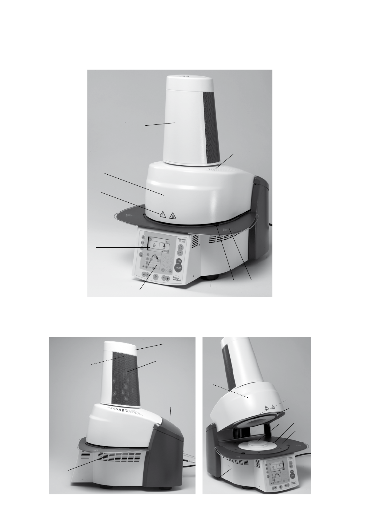
List of parts
1 Sealing surface
2 Furnace head sealing ring
3 Insulation
4 Thermocouple
5 Firing plate 2
6 Display
7 Frame plate
8 QTK heating muffle
9 Housing base
10 Keypad (membrane-sealed)
11 On/Off switch
12 Heating element fuse
13 Vacuum pump fuse
15 Fuse holder
16 Power cord
17 Power socket
18 Vacuum pump socket
19 Rating plate
20 Screw for furnace head cover
21 Vacuum hose connection
22 Head insulation
23 Rubber feet
25 Housing furnace head
26 Thermocouple plug
27 Plug fuse
28 Heater plug
29 Heater plug socket
30 Thermocouple plug socket
32 Leaf spring
33 Air vents (base)
34 Cooling tray
35 Screw for cooling tray
36 Hood
37 Knurled screw for hood
38 Air vents furnace head
39 Air vents rear panel
40 Warnings
41 Furnace head mounting mark
42 Furnace base mounting mark
43 Furnace head mounting
44 Quartz-glass tube
46 Vacuum hose
47 Silicone washer
48 Firing plate holder
49 Thermocouple cable
50 Connecting rod axis
53 USB interface
54 Plug-in console
56 Cover for press drive
58 Furnace head, compl.
59 Press plunger 120
60 Press drive plug
61 Press electronics
62 Cover for press electronics
63 Fan
64 Split taper socket for press plunger
65 Terminal screw for press plunger
66 Press drive cable
67 Press drive plug socket
Please note that the list of parts applies to the entire
Operating Instructions. These parts and their numbers are
4
often referred to in later chapters.
Page 5
56
38
25
40
6
34
35
23
10
33
63
58
20
36
3
8
2
1
5
7
9
5
Page 6
22
59
64
65
62
11
36
12
13
53
19
37
39
61
63
22
12
11
15
13
53
19
32
21
46
17
16
18
43
49 2666 30 60 67 29 27 28 11
6
Page 7
8
59
Control unit:
4
44
3
54
50
41
42
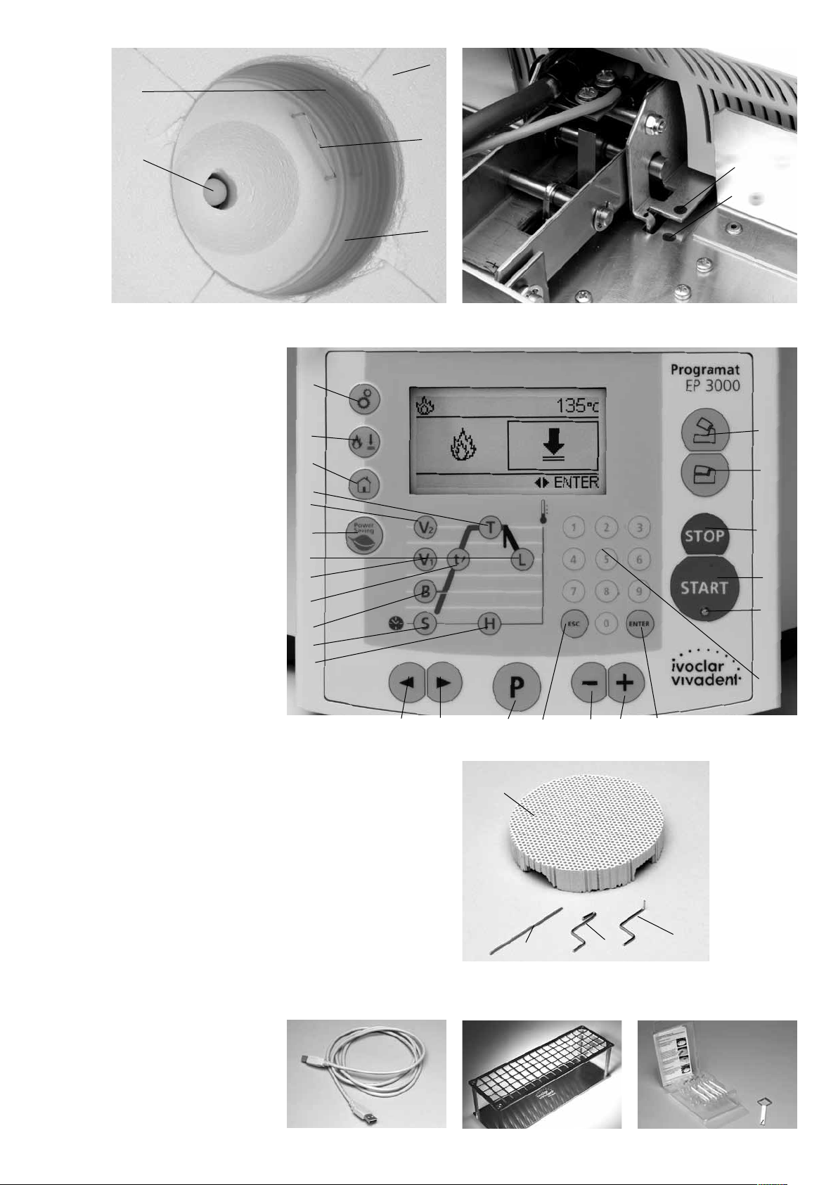
70 Program key
71 ESC key
72 ENTER key
73 START key
74 Start LED
75 STOP key
76 Plus key
77 Minus key
78 Settings / Information
79 Cursor key right
80 Cursor key left
81 Stand-by temperature
82 Closing time
83 Temperature increase
84 Holding temperature
85 Holding time
86 Vacuum on
87 Vacuum off
88 Long-term cooling
89 Power Saving key
90 Open furnace head
91 Close furnace head
92 Numeric keys
93 Firing / Pressing
94 Home key
78
93
94
84
87
89
88
86
83
81
82
85
90
91
75
73
74
92
79 80 70 77 76 72 71
100
100 Programat firing tray
101 Metal pin A
102 Metal pin B
103 Metal pin C
110 USB data cable
110
102
115 Cooling grid (complete)
7
103
115
101
120 Automatic Temperature
Checking Set 2 – ATK 2
120
Page 8
1. Introduction / Signs and Symbols
1.1 Preface
Dear Customer
Thank you for having purchased
the Programat EP 3000/G2. It is
a state-of-the-art furnace for
dental applications.
The furnace has been designed
according to the latest industry
standards. Inappropriate use
may damage the equipment and
be harmful to personnel. Please
observe the relevant safety
instructions and read the
Operating Instructions carefully.
Enjoy working with the
Programat EP 3000/G2.
1.2 Introduction
The signs and symbols in these
Operating Instructions and on
the furnace facilitate the finding
of important points and have
the following meanings:
Risks and dangers
Important
information
Contraindication
Burn hazard
Risk of crushing
The Operating
Instructions must
be read
1.3 Notes regarding the
Operating Instructions
Furnace concerned:
Programat EP 3000/G2
Target group:
Dental technologists
These Operating Instructions
facilitate the correct, safe, and
economic use of the Programat
EP 3000/G2 furnace.
Should you lose the Operating
Instructions, extra copies can be
ordered at a nominal fee from
your local Ivoclar Vivadent
Service Center or downladed
from www.ivoclarvivadent.com/
downloadcenter.
In the Operating Instructions,
the furnace is described in the
200–240 V voltage version.
Please note that the voltage
range shown on the images
(e.g. rating plate) may differ
depending on the voltage
version of your furnace.
1.4 Notes on the different
voltage versions
The furnace is available with
different voltage versions.
– 110 – 120 V / 50 – 60 Hz
– 200 – 240 V / 50 – 60 Hz
In the Operating Instructions,
the furnace is described in the
200 – 240 V voltage version.
Please note that the voltage
range shown on the images
(e.g. rating plate) may differ
depending on the voltage
version of your furnace.
8
Page 9
2. Safety First
This chapter is especially important for personnel who work with the
Programat EP 3000/G2 or who have to carry out maintenance or
repair work. This chapter must be read and the corresponding
instructions followed.
2.1 Indications
The Programat EP 3000/G2 must only be used to fire and/or press
dental ceramic materials and it should be used for this purpose only.
Other uses than the ones stipulated, e.g. cooking of food, firing of
other materials, etc., are contraindicated. The manufacturer does not
assume any liability for damage resulting from misuse. The user is
solely responsible for any risk resulting from failure to observe these
Instructions.
Further instructions to assure proper use of the furnace:
– The instructions, regulations, and notes in these Operating Instruc-
tions must be observed.
– The instructions, regulations, and notes in the material‘s Instruc-
tions for Use must be observed.
– The furnace must be operated under the indicated environmental
and operating conditions (see Chapter 9).
– The Programat EP 3000/G2 must be properly maintained.
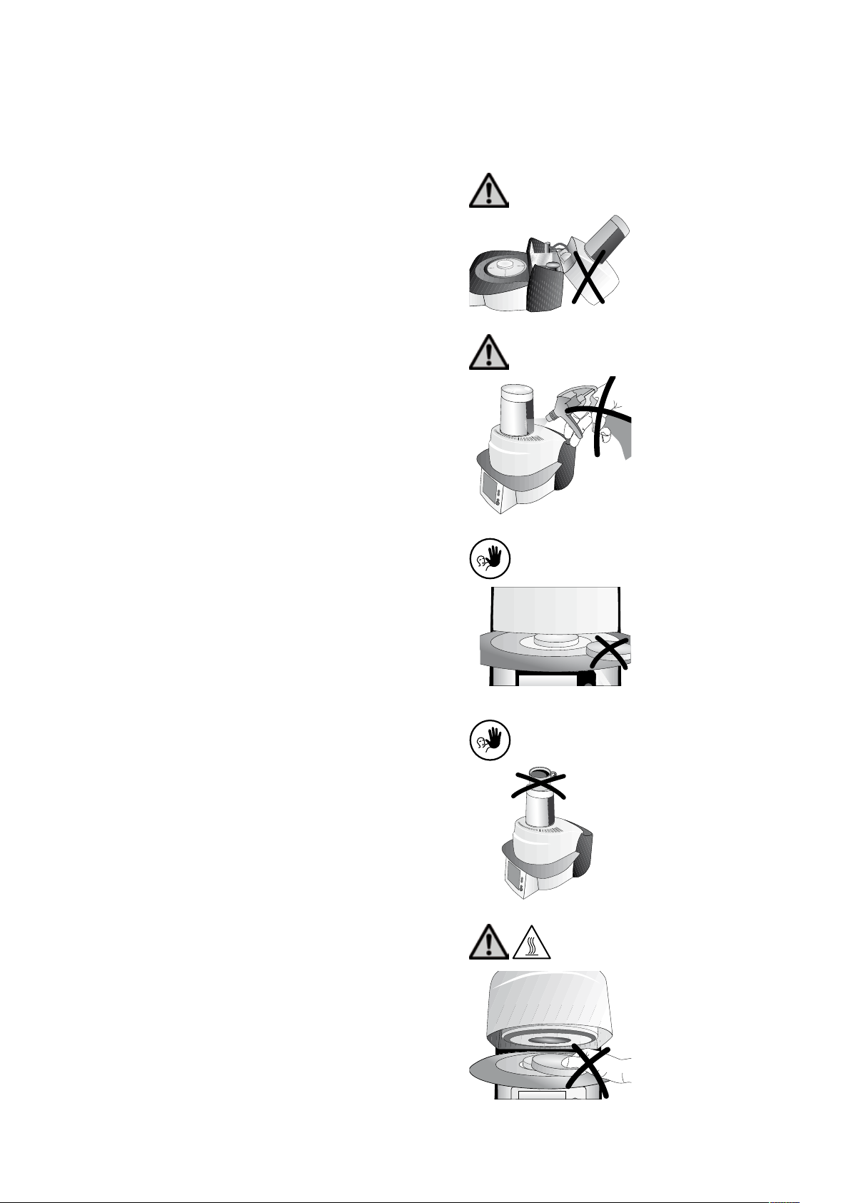
2.1.1
Risks and dangers
The furnace head should not be
removed from the furnace base as
long as the furnace head is connected by means of the heater
cable.
2.1.2
Risks and dangers
Make sure that no liquids or other
foreign objects enter the furnace.
2.1.3
Contraindication
Firing trays must not be placed in
the area surrounding the firing
table, since this will obstruct the
closing of the furnace head.
2.1.4
Contraindication
Foreign objects must not be
placed on the furnace head or air
vents. Make sure that no liquids or
other foreign objects enter the air
vents, since this may result in an
electrical shock.
2.1.5
Risks and dangers, burn hazard
Never place objects in the firing
chamber by hand, since there is a
burn hazard. Always use the tongs
(accessories) supplied for this
purpose. Never touch the hot
surface of the furnace head, as
there is a burn hazard. Please also
refer to the warnings on the
furnace.
9
Page 10
2.1.6
2.1.11
Risks and dangers
2.1.7
Risks and dangers
2.1.8
Risks and dangers
Do not carry the furnace by the
cooling tray.
Do not carry the furnace head by
the cables, since the cables and
connections may be damaged.
The furnace head is equipped with
an electric drive and must be
operated by means of the
electronic controls. Never open
the furnace head by hand, since
the mechanism will be damaged.
Risk of crushing and burn hazard
Never reach under the furnace
head with the hand or other parts
of the body during operation,
since there is a risk of crushing
and a burn hazard.
2.1.12
Contraindication
Do not insert any foreign objects
into the air vents. There is a risk of
electrical shock.
2.1.13
Contraindication
This product contains ceramic
fibres and may release fibre dust.
Do not use compressed air, or
blow on the furnace thus
distributing the dust in the
environment and observe the
additional notes on page 11.
2.1.9
Contraindication
2.1.10
Contraindication
Never use the furnace without a
firing table.
Do not touch the thermocouple or
the quartz tube in the firing
chamber. Avoid contact with the
skin (grease contamination), as the
parts may be damaged.
2.1.14
Contraindication
Do not cool the hot investment
ring on the cooling tray. Use only
the cooling grid for that purpose.
2.1.15
Risks and dangers
The furnace must not be operated if the quartz tube or
the insulation in the firing chamber is damaged. There is a risk of
electric shock upon contact with the heating wire.
Avoid any damage of the insulation by contact with the investment
tongs or firing tongs. Make sure to keep the firing plate for the
investment ring clean.
2.1.16
Contraindication
Only use original ring bases from Ivoclar Vivadent. Observe
the maximum height (57 mm) and diameter (35 mm, 50 mm and
65 mm) of the investment ring.
10
Page 11
2.2 Health and safety instructions
This furnace has been designed according to EN 61010-1 and has
been shipped from the manufacturer in excellent condition as far as
safety regulations are concerned. To maintain this condition and to
ensure risk-free operation, the user must observe the notes and
warnings contained in these Operating Instructions.
– Place furnace on a fire-proof table (observe local regulations, e.g.
distance to combustible substances or objects, etc.).
– Always keep the air vents at the rear of the furnace free from
obstruction.
– Do not touch any parts that become hot during operation of the
furnace. There is a burn hazard.
– Clean furnace only with a dry or slightly moist cloth. Do not use
any solvents. Disconnect power before cleaning.
– Use original packaging for transportation purposes.
– The furnace must be cool before it is packed for transportation.
– The user must especially become familiar with the warnings and
operating conditions to prevent injury to personnel or damage to
materials. The manufacturer is not responsible for damage
resulting from misuse or failure to observe the Operating
Instructions. Warranty claims cannot be accepted in such cases.
– Before switching on the furnace, make sure that the voltage
indicated on the rating plate complies with your local power
supply.
– The power socket must be equipped with a residual current circuit
breaker.
– The furnace must be plugged into a socket with protected contacts.
– Before calibration, maintenance, repair, or exchange of parts, the
power must be disconnected if the furnace is to be opened.
– If calibration, maintenance, or repair has to be carried out with
the power connected and the furnace open, only qualified
personnel, who are familiar with the risks and dangers, may
perform these procedures.
– After maintenance, the required safety tests (high voltage
resistance, protective conductor, etc.) have to be carried out.
– Ensure that only fuses of the indicated type and rated current are
used.
– If it is assumed that safe operation is no longer possible, the power
must be disconnected to avoid accidental operation. Safe operation
is no longer possible if
– the furnace is visibly damaged
– the furnace does not work
– the furnace has been stored under unfavourable conditions
over an extended period of time
– Use only original spare parts.
– The temperature range for faultless operation is +5 °C to +40 °C
(41 °F to 104 °F).
– If the furnace has been stored at very low temperatures or high
atmospheric humidity, the head has to be opened and the unit
dried or left to adjust to room temperature for approx. 1 hour (do
not connect the power yet).
– The furnace has been tested for use at altitudes of up to 2000 m
above sea level.
– The furnace may only be used indoors.
– Do not run the furnace via an extension cord.
– When placing and removing the investment ring, make sure not
to hit the insulation of the firing chamber.
– There is a burn hazard at the cooling tray if the furnace is
continuously operated in the press mode (stand-by = 700 °C).
Any disruption of the protective conductor either inside
or outside the furnace or any loosening of the protective
conductor connection may lead to danger for the user in
case of a malfunction. Deliberate interruptions are not
tolerated. Materials developing harmful gases must not
be fired.
Warnings regarding the removal of the heating muffle
This product contains ceramic fibres and may release fibre
dust. Fibre dust has proved to be carcinogenic in animal
The heating muffle must only be disassembled by a certified After
Sales Service Centre. Information regarding the Safety Data Sheet is
also available from your After Sales Service Centre.
Warning
The insulation on this product contains refractory ceramic fibres (RCF)
which pose a possible cancer hazard, if agitated and inhaled. May be
irritating to the skin, eyes or respiratory tract if insulation is cracked
or corrupted.
California Proposition 65
Warning: ”This product contains Refractory Ceramic Fibres, a
substance known to the State of California to cause cancer.”
11
experiments.
Disposal:
The furnaces must not be disposed in the normal
domestic waste. Please correctly dispose of old
furnaces according to the corresponding EU council
directive. Information on the correct disposal may
also be found on your local Ivoclar Vivadent
homepage.
Page 12

3. Product Description
3.1 Components
The Programat EP 3000/G2
comprises the following
components:
– Furnace base with electronic
controls
– Furnace head with firing
chamber and press drive
– Firing plate
– Cooling tray
– Power cord and hose for
vacuum pump
– Vacuum pump (accessories)
3.2 Hazardous areas and safety equipment
Description of the hazardous areas of the furnace:
Hazardous area Type of risk
Firing chamber Risk of burning
Opening/closing mechanism Risk of crushing
Electrical components Risk of electrical shock
Description of the safety equipment of the furnace:
Safety equipment Protective effect
Protective conductor Protection from electrical shock
Electrical fuses Protection from electrical shock
Housing and covers Protection from electrical shock, burn hazard and
crushing
3.3 Functional description
The firing/pressing chamber may be heated up to
max. 1200 °C (2192 °F) by means of a heating
element. Furthermore, the firing chamber has
been designed in such a way that a vacuum may
be created with a vacuum pump. The presssure for
the press procedure is generated by a press drive.
The firing/pressing programs are controlled with
the corresponding electronic controls and
software. Moreover, the set and actual temperatures are continuously compared.
3.4 Accessories
(not part of the delivery form)
– Automatic Temperature Checking Set 2 (ATK 2)
– Programat Accessories Set 2 (Programat firing
trays, Silicone Nitride Firing Tray “K”, firing
tongs, Automatic Temperature Checking Set 2)
– Vacuum pump
12
Page 13

4. Installation and Initial Start-Up
4.1 Unpacking and checking the contents
The packaging provides the following advantages:
– Reusable packaging
– Closing mechanism with integrated transportation grips
– Ideal protection by Styrofoam inserts
– Easy handling / optimum unpacking
– The packaging may be used in several ways (modules)
Check the delivery for completeness (see delivery form in Chapter 9)
and transportation damage. If parts are damaged or missing, contact
your local Ivoclar Vivadent Service Center.
There are no special transportation grips on the furnace. Support the
bottom of the furnace to carry it.
4.2 Selecting the location
Place the furnace on a flat table using the rubber feet. Make sure
that the furnace is not placed in the immediate vicinity of heaters or
other sources of heat. Make sure that air may properly circulate
between the wall and the furnace.
Also ensure that there is enough space between the furnace and the
user, as the furnace releases heat during the opening of the furnace
head.
The furnace should neither be placed nor operated in areas
where there is an explosion hazard.
4.3 Assembly
Make sure the voltage indicated on the rating plate (19) complies
with the local power supply. If this is not the case, the furnace must
not be connected.
Remove furnace components from their packaging and place the
unit on a suitable table. Please observe the instructions on the outer
packaging.
Packing and shipping of individual components
The packaging of the EP 3000/G2 permits simple and safe shipping
of individual components. Simply use the two corresponding inserts.
Fold the side flaps and combine the two parts by means of the
transportation flaps. The packaging may be disposed with the
regular household refuse.
We recommend keeping the original packaging for future
service and transportation purposes.
19
Step 1:
Assembling the cooling tray (34)
Remove both screws (35) including the silicone washer (47) for the
cooling tray (34).
35
35
47
47
13
Page 14

Place the cooling tray (34) on the frame plate (7).
Make sure that the cooling tray (34) is
correctly positioned on the frame plate (7).
Secure the cooling tray (34) with the two screws
(35) including the silicone washer (47).
34
7
Step 2:
Mounting the furnace head
The complete furnace head (58) is best mounted
with the rear panel of the furnace pointing
towards the user. Lift the furnace head with both
hands (see picture) and carefully position it on the
furnace head mounting (43).
35
47
58
14
Page 15

Ensure that the furnace head mounting mark (41)
is aligned with the furnace base mounting mark
(42).
Make sure that the firing plate
holder (48) is not damaged by
mounting the furnace head.
Step 3:
Placing the firing plate for the investment
ring (5)
The firing plate for the investment ring (5) can
now be placed on the firing plate holder (48).
54
50
41
42
Step 4:
Connections
Connect the cables of the furnace head with the
furnace base. Proceed as follows:
– Insert the thermocouple plug (26) (make sure
that the polarity of the plug is correct)
– Insert the heater plug (28)
– Insert the press drive plug (60)
5
48
28
26
60
27
15
Page 16

Secure the heater plug (28) with the plug fuse (27)
by turning it until the heater plug (28) has been
secured.
27
28
Step 5:
Mounting the hood (36)
Once all cables are properly connected to the
furnace base, the hood (36) can be mounted.
Subsequently, secure the hood with the knurled
screw (37).
The furnace may only be operated with
the hood mounted.
Step 6:
Establishing additional connections
Power connection
Please make sure that the voltage indicated on the
rating plate complies with the local power supply.
Connect the power cord with the power socket of
the furnace (17).
Vacuum pump connection
Connect the vacuum pump plug with the vacuum
pump socket (18).
We recommend using only the VP4 vacuum pump
from Ivoclar Vivadent, since this pump is especially
coordinated with the furnace.
If other pumps are used, please observe and do
not exceed the maximum power consumption.
36
37
21
17
16
18
16
Page 17

4.4 Removing the furnace head
Before the hood (36) is removed, the furnace has
to be switched off and the power cord
disconnected from the power socket (17).
1. Loosen and remove the knurled screw (37) of
the hood (36)
2. Remove the hood (36)
3. Disconnect the press drive plug (60)
4. Disconnect the thermocouple plug (26)
5. Disconnect the heater plug (28)
6. Press the leaf spring (32) with a finger, lift off
the furnace head at the same time and
remove it
Make sure the furnace head has
completely cooled down before it is
removed (fire hazard).
17
Page 18

4.5 Initial start-up
1. Connect the power cord with the wall socket.
2. Put the On/Off switch (11) at the rear of the furnace on position
„I“ and connect the vacuum pump.
4.5.1 Start screen
Immediately after switching on, the display briefly shows the start
screen.
4.5.4 Basic build-up of screens
The different areas of the screen are shown with the press program
stand-by and operating screens as examples.
The uppermost line mainly shows status information. In the central
and largest area, important information of the respective screen are
displayed. The lowest line provides information about possible
activities (keystrokes). The command keys (Open furnace head, Close
furnace head, STOP, START keys) are not shown for reasons of clarity.
4.5.2 Self-test
The furnace will automatically conduct a self-test after start. The performance of all furnace components is automatically checked. The
display shows the following indications during the self-test:
1 Software version
1
2 Status bar
2
3 Firing hours
4 Current power supply
4
3
If a component is defective, the corresponding error number (ER xxx)
will be indicated in the display.
4.5.3 Selecting the operation mode
After the self-test, the selection screen for the operation mode will
be displayed. It is used to select the general operation mode (firing
or pressing). The operation mode selection can also be shown via the
Firing / Pressing key (93) if no program is active.
The cursor position (frame around
the symbol) can be changed by
means of the Cursor keys. The
marked operation mode can
finally be selected using the Enter
key.
This information is only shown if
the operation mode has been
changed. Make sure that the
furnace runs at the new stand-by
temperature long enough before
you start a program.
Operation mode
Status area
Main area
Recommendation
area
Furnace
temperature
Selected program,
investment ring
Possible
keystrokes
Use the ESC key to quit such messages (Info, Hint, Error). The
acoustic signal can be stopped any time by pressing the STOP key.
18
Page 19

5. Operation and Configuration
5.1 Introduction to the operation
The Programat EP 3000/G2 is equipped with a graphical display with
backlighting. The furnace can be operated by means of the
membrane-sealed keypad. In addition, the parameters can be
selected directly by means of the Parameter firing curve with the
Parameter keys.
The numeric and command keys can be used to program and
control the furnace.
78
93
94
84
87
89
88
86
83
81
82
85
79 80 70 77 76 72 71
90
91
75
73
74
92
5.2 Explanation of the key functions
– Firing / Pressing (93)
Selection of the firing or pressing mode
– Program key (70)
This key is used to switch between the parameter screen and the
stand-by screen (or operation screen).
– START key (73)
Starts the selected program. The fact that the program is running
is indicated by the green Start LED. If the program is interrupted
(1x STOP), the Start LED flashes until renewed pressing of START
results in the program being resumed.
– STOP key (75)
A program in progress can be interrupted by pressing STOP once.
Pressing STOP twice will abort the program. Movement of the
furnace head can be stopped at any time by pressing STOP.
The beeper can be confirmed by pressing the STOP key.
– ESC key (71)
Ends an entry without accepting the value. Return from the
current to the previous screen. Confirmation of error messages.
– ENTER key (72)
Confirmation of entered numeric value. Selection of a setting or a
test program.
– Numeric keys (92)
Used to enter numeric values.
– Cursor key left, right (80, 79)
These keys can be used to move the cursor (e.g. for selecting the
operation mode, size of the investment ring, parameter program-
ming, etc.). In addition, the displayed program, information or
setting can be changed.
– Minus and Plus keys (77, 76)
These keys can be used to change the numeric value displayed or
marked with the cursor.
– Settings / Information (78)
This key shows the selection (Information / Settings). The Left key
shows the information screen. The Right key shows the settings
screen.
– Open furnace head (90)
Opening of the furnace head in 5 seconds.
– Close furnace head (91)
Closing of the furnace head in 5 seconds.
– T = Holding temperature (84)
Shows the holding temperature (actual firing temperature).
– H = Holding time (85)
Shows the holding time (actual firing time).
– S = Closing time (82)
Indicates the closing time of the furnace head (preheating time).
– B = Stand-by temperature (81)
Indicates the stand-by temperature.
– t = Temperature increase (83)
Shows the temperature increase per minute for the heating
process (°C/min or °F/min).
– V1 Vacuum on temp. (86)
Shows the temperature at which the vacuum is switched on.
– V2 Vacuum off temp. (87)
Shows the temperature at which the vacuum is switched off. If
this temperature corresponds to the Holding temperature T, the
vacuum remains on during the entire holding time.
Special case: If this temperature V2 is exactly 1 °C (or 1 °F) higher
than the Holding temperature T while long-term cooling is active,
the vacuum remains on during the entire long-term cooling.
– L = Long-term cooling (88)
Determines the temperature point at which the furnace head
should be opened after completion of the Holding time and free
or controlled (tL) cooling.
– Power-saving key (89)
Power-saving function activated (only possible with the furnace
head closed and the furnace on idle). The display shows the
power-saving icon. Pressing any key ends the power-saving
function.
– tL = Controlled cooling - temperature decrease rate
(°C/min or °F/min)
– Home key (94)
Return to ”Program selection Indication“.
19
Page 20

5.3 Program structure
5.3.1 Firing programs
All the firing programs are equivalent and,
therefore, full-fledged programs. In each program,
all the parameters can be adjusted.
a) Ivoclar Vivadent firing programs for Ivoclar
Vivadent materials
When the furnace is delivered ex works, the
Ivoclar Vivadent firing programs already contain
the recommended material parameter settings.
Moreover, the programs are write-protected.
Consequently, it is not possible to accidentally
overwrite the parameters.
Please refer to the respective program table (list
of parameters) in Chapter 10.
However, the parameters are designed in such
a way that they can be changed and overwritten at any time, if the programs are to be
used for other purposes. Therefore, these
programs are also available as free, individual
programs.
b) Individual firing programs
The individual firing programs (at least 300) can
be programmed freely.
5.3.2 Press programs
a) Ivoclar Vivadent press programs for Ivoclar
Vivadent materials
When the furnace is delivered ex works, the
standard press programs already contain the
recommended material parameter settings.
They cannot be adjusted.
b) Individual press programs
The individual press programs (20) can be
programmed freely.
5.4 Adjustable parameters and possible value ranges
Symbol Parameter Value range °C Value range °F
P Program number 1-300
B Stand-by temperature 100-700 °C 212-1292 °F
S Closing time (min : sec) 00:18-30:00
t Temperature increase rate 10-140 °C/min 18-252 °F/min
T Holding temperature 100-1200 °C 212-2192 °F
H Holding time (min : sec) 00.01-60:00
V1 Vacuum on 0 or 1-1200 °C 0 or 34-2192 °F
V2 Vacuum off 0 or 1-1200 °C 0 or 34-2192 °F
L Long-term cooling 0 or 50-1200 °C 0 or 122-2192 °F
tL Cooling temperature rate 0 or 1-50 °C 0 or 2-90 °F/min
t Temperature increase rate 2
T2 Holding temperature 2nd stage 100-1200 °C/min 212-2192 °F
H2 Holding time 2nd stage (min : sec) 00.01-60:00
V1 2 Vacuum on temp. 2
V2 2 Vacuum off temp. 2
Automatic plausibility check
The furnace is equipped with an automatic plausibility check function. The parameters
(e.g. T 960 but L 1000) are checked upon each program start.
In case of contradictory parameter combinations, the program stops automatically and
the respective error number is indicated.
nd
stage 10-140 °C/min 18-252 °F/min
nd
stage 0 or 1-1200 °C 0 or 34-2192 °F
nd
stage 0 or 1-1200 °C 0 or 34-2192 °F
20
Page 21

5.5 Settings, special programs and information
This screen can be selected via the
Settings / Information key (78) if
no program is active.
The cursor position (frame around
the symbol) can be changed by
means of the Cursor keys. The
marked symbol (Information or Settings) can finally be selected using the Enter key.
5.5.1 Settings
Once the Settings have been
selected, the first page of the
Settings is displayed. The current
page number is shown in the
upper line.
The displayed page (Setting) can
be changed using the Cursor keys.
If the Minus/Plus keys are shown, the displayed Setting (e.g.
Contrast) can be edited with the Minus/Plus keys.
If the ENTER key is shown, the displayed Setting or Test program
(e.g. Calibration) can be confirmed with the ENTER key.
The ESC key can be used to return to the previous screen.
Page Description
1/24 Contrast
2/24 Temperature
mode
Indication on display Short description
The contrast can be
set within the displayed limiting values
using the Minus/Plus
keys.
The Minus/Plus keys
can be used to
toggle between °C
and °F.
Page Description
7/24 Date
8/24 General
write
protection
9/24 „Ivoclar
Vivadent
optimized
temperature
control“
10/24 Power-Saving
mode
11/24 Service interval
12/24 Protocolling
13/24 Vacuum
test program
Indication on display Short description
The date can be
entered using the
Numeric keys.
The general write
protection can be
activated or deactivated using the
Minus/Plus keys. The
general write protection locks all firing
programs. The user
code is required.
The STD code is
required.
The automatic
power-saving mode
can be activated and
deactivated with the
+ or – key (for additional information,
see section 6.3.10)
Here you can set the
interval for the
service notes to be
displayed (Hint
1700).
The automatic protocol function can
be activated or
deactivated with the
+ or – key.
See Chapter 5.5.2
Special programs.
3/24 Calibration
program
ATK2
4/24 Volume
5/24 Buzzer tunes
6/24 Time
This program is used
to conduct the automatic temperature
calibration with the
ATK2. Please
observe the notes in
Chapter 7.4.
The Minus/Plus keys
can be used to set
the desired volume.
The Minus/Plus keys
can be used to set
the desired buzzer
tunes.
The time can be
entered using the
Numeric keys.
14/24 Heater
test program
15/24 Keypad
test program
16/24 Cleaning
program
17/24 Dehumidifica tion program
21
See Chapter 5.5.2
Special programs
See Chapter 5.5.2
Special programs
See Chapter 5.5.2
Special programs
See Chapter 5.5.2
Special programs
Page 22

Page Description
18/24 Load
factory
settings
19/24 Set
the firing
hours of the
furnace head
to zero
20/24 Set the
vacuum pump
hours to zero
21/24 Calibration
interval
22/24 Press
calibration
interval
23/24 Dehumidifica tion interval
24/24 Ivoclar
Vivadent AG
Indication on display
Short description
Resets the values
and parameters to
the factory settings.
NOTE: All individual
programs you have
created and saved
will be deleted with
this function. The
user code is required.
Resets the
determined firing
hours.
The user code is
required.
Resets the
determined vacuum
pump hours.
The user code is
required.
Ex works:
12 months (another
1, 3 and 6 months
are possible). Afterwards, a reminder
for temperature
calibration appears.
Ex works:
100 press cycles.
Afterwards, a
reminder for the
temperature
calibration appears.
Ex works:
12 months. Afterwards, a reminder
for the dehumidification program
appears.
Only for the After
Sales Service.
5.5.2 Special programs
5.5.2.1 Vacuum test program
With this vacuum test program, the performance of the vacuum system can be automatically tested. For that purpose, the achieved
(minimum) pressure in mbar is measured and indicated. If the
pressure value is below 80 mbar (hPa), the vacuum performance of
the system is adequate.
5.5.2.2 Heater test program
The quality of the heating muffle may be automatically checked by
means of the heater test (duration: approx. 7 min.). The heater test
should only be conducted with the empty firing chamber, since an
object in the chamber (e.g. firing tray) may influence the test result.
Conduct the heater test immediately after switching on the furnace
and before any actual firing procedures. If the furnace is too hot, an
incorrect heating muffle quality will be indicated. If the heating
element quality falls below 50%, replacing the heating element is
recommended.
5.5.2.3 Keypad test
Each time the keypad is pressed, a short beep sounds. The keypad
test can be ended by pressing ESC.
5.5.2.4 Cleaning program
The cleaning program is used to „clean“ the heating muffle
(duration: approx. 17 min.) After a cleaning program, it is
recommended to calibrate the furnace. In case of problems with
discolouration of the ceramic, we recommend replacing the firing
tray material.
5.5.2.5 Dehumidification program
The condensation of water in the insulation of the firing chamber
and the vacuum pump will result in a lower vacuum and thus to
impaired firing results. For that reason, the furnace head should be
kept closed when the furnace is switched off or is below 100 °C, in
order to prevent the absorption of humidity. Start the dehumidification program if required (humidity in the insulation).
5.5.3 Information
Once the Information has been
selected via the Settings / Information key (78), the first page of the
Information is displayed. The
current page number is shown in
the upper line.
The displayed page (Information) can be changed using the Cursor
keys.
The ESC key can be used to return to the previous screen.
The user code (6725)
is required for some
Settings.
22
Page 23

Page Description
Indication on display Short description
5.6 Explanation of the symbols on the display
1/11 Serial number
2/11 Software
version
3/11 Firing hours
of the furnace
head
4/11 Operating
hours of the
furnace
5/11 Operating
hours of the
vacuum pump
6/11 Last start
of the
calibration
program
7/11 Calibration
values
8/11 Press
procedures
since the last
calibration
9/11 Last start
of the
dehumidifica tion program
10/11 Power supply
Serial number of the
furnace, see also rating plate.
Calibration values at
660 °C and 962 °C.
Number of press
cycles since the
last start of the
calibration program.
Shows the current
supply voltage.
Symbol name
„One-stage
program“
„Two-stage
program“
„Two-stage
program“
„Standard opening
of the furnace head“
(toggle with Minus/
Plus keys)
„Quick opening of
the furnace head“
(toggle with Minus/
Plus keys)
Predrying
„Thermo Shock
Protection“
Standard closing of
the furnace head
Open lock
Closed lock
Meaning
Shows that a
standard one-stage
firing program is used
Shows that a twostage special program
is used. The bold line
shows that the values
of the first stage are
displayed.
Shows that a twostage special program
is used. The bold line
shows that the values
of the second stage
are displayed.
Shows that the
furnace head opens
with standard speed
after firing.
Shows that the
furnace head opens
quickly after firing.
Shows that the
option „Predrying“
was activated.
Thermo Shock
Protection active
Predrying and Thermo
Shock Protection are
inactive
„Individual write
protection inactive“
„Individual write
protection active“
Symbol
11/11 Error messages
Shows the last error
messages
„General write protection active“
„Paging“
Operation mode
Firing
Pressing or note on
active press process
23
All programs are
write-protected.
To change pages in
the Parameter screen;
only for two-stage
firing programs.
For selecting the Firing
mode.
For selecting the Press
mode. If the press
process has been
started, this symbol is
shown next to the
remaining pressing
time.
Page 24

Symbol name
Meaning
Symbol
Information
Settings
For additional explanations on the symbols and the corresponding
functions please refer to Chapter 6.4 „Other options and special
features of the furnace“.
For selecting the Information screen.
For selecting the
Settings screen.
5.7 Explanation of the beeper signals
Basically, the buzzer tunes and volume set by the user are used for all
acoustic signals.
The beeper can only be ended by pressing the STOP key.
1 After the self-test is completed
To inform the user that the automatic self-test has been
successfully completed, the selected melody is played.
2 Furnace head open and temperature below 550 °C / 1022 °F
To inform the user that the temperature in the open furnace head
has dropped below 550 °C / 1022 °F, the selected melody is
played (5 seconds). In other words, the furnace head is basically
cool enough for the next program start.
3 Furnace head open and temperature below 320 °C / 608 °F
To inform the user that the temperature in the open furnace head
has dropped below 320 °C / 608 °F, the selected melody is
played.
If the first playback (10 seconds) is not acknowledged with the
STOP key, a second playback sounds after 5 minutes (for
5 minutes). After that, no further signal is played.
If one of the two playbacks is acknowledged with the STOP key,
the signal transmitter is switched off immediately and no further
signals indicating the cooled furnace head will be sounded.
4 For error messages
Error messages are acoustically supported with the ‚error melody‘
(endless beep). The signal transmitter may be switched off with
the STOP key, while the error message still remains visible. If the
error message is acknowledge with the ESC key, the signal
transmitter is also switched off.
24
Page 25

6. Practical Use
6.1 Switching on/off
Put ON/OFF switch on position “I”. The furnace conducts an automatic self-test, which will be indicated in the beginning.
Subsequently, a status bar shows how many % of the self-test have
been completed. Make sure that the furnace is not manipulated during this time.
After successful completion of the self-test, the main menu is shown
in the display.
6.2 Firing programs
6.2.1 Selecting the type of firing program
Once the Firing mode has been
selected, the firing program type
screen is displayed. There is a
choice between Ivoclar Vivadent
firing programs for Ivoclar Vivadent
materials and free, individual firing
programs.
The cursor position (frame) can be
changed by means of the Cursor keys. The marked type of firing
program can finally be selected using the Enter key.
6.2.2 Selecting the type of firing program and stand-by screen
(firing program)
Once the desired type of firing
program has been selected, the
firing program screen is displayed.
This screen corresponds to the
stand-by screen of the firing
programs.
– The displayed (selectable) firing program can be changed using
the Cursor keys. The displayed firing program can finally be select-
ed using the Enter key.
– The Program key can be used to change to the parameter screen
(firing program).
– The ESC key can be used to change to the selection of firing
program types.
– Program write protection and general write protection
The standard firing programs for Ivoclar Vivadent materials have
been locked ex works with an active program write protection
(closed lock), which can be deactivated by the user for each
program using the Minus/Plus keys.
The individual firing programs are open ex works, i.e. the program
write protection is not active (open lock).
If the superordinate „General write protection“ was activated via
Settings and user code, the „General write protection symbol“ is
displayed instead.
– Indication of invalid entry
The blinking exclamation mark (!) indicates an invalid entry. For
further notes please refer to Chapter 6.3.2.
– Predrying
If the predrying function was activated, the respective symbol is
shown in the parameter screen. For further notes please refer to
Chapter 6.3.6.
– Standard / quick opening of the furnace head
The opening time of the furnace head at the end of the firing
program (standard: 60 seconds, quick: 18 seconds) can be
changed by means of the Minus/Plus keys. For further notes
please refer to Chapter 6.3.7.
– One-/two-stage program
If the cursor is positioned on the „Program stage symbol“, the
program can be selected as one- or two-stage program using the
Minus/Plus keys. For further notes please refer to Chapter 6.3.8.
– Displaying the parameters of the first/second stage (only for
two-stage programs)
If the cursor is positioned on the „Paging symbol“, it is possible to
toggle between the parameters of the first and second stage
using the ENTER key.
6.2.4 Parameter detail screen (firing program)
These parameter details can be displayed in the firing mode by
pressing the corresponding keys ().
6.2.3 Parameter screen (firing program)
The Program key can be used to change to the parameter screen (firing program) anytime. Every time the Program key is pressed, it is
possible to toggle between the stand-by or operation screen and the
parameter screen.
The cursor position can be moved between the parameters by means
of the Cursor keys. The marked parameter (or function symbol) can
be edited with the Minus/Plus keys or via the numeric keys and
confirmed by pressing ENTER. Examples:
The ESC key can be used to return to the previous screen.
The displayed parameter can be
edited with the Minus/Plus keys or
via the numeric keys and confirmed
by pressing ENTER. The
acceptable value range is shown for
information purposes to avoid
incorrect entries.
6.2.5 Operation screen (firing program)
Operation screen while a firing program is in progress.
a)
e)
f)
The following information is shown in this screen:
a) Program group
b) Program number
c) Remaining time
d) Current temperature
e) Status of vacuum *)
f) Status bar in the firing curve
d)
b)
c)
25
Page 26
If a two-stage program is selected, the firing curve is shown in two
stages. During a firing program in progress, the parameter screen or
operation screen may be displayed at any time for information purposes by pressing the P key. However, the parameters may only be
changed with the program stopped or the furnace in stand-by mode.
*) The vacuum indication is faded out if no vacuum is needed.
6.2.6 Firing using an Ivoclar Vivadent program
Step 1:
Select the desired firing program according to the program table
(Chapter 10).
Selecting the
operation
mode
Selecting the
firing program
type
Selecting the
firing
program and
stand-by
screen
6.3 Press programs
6.3.1 Pressing using an Ivoclar Vivadent program
Selecting the
operation
mode
Selecting the
press program
type
Selecting
the press
program
Investment
ring
selection
Parameter screen
Stand-by
screen
Parameter screen
Operation
screen
Step 2:
Open the furnace head with the „Open furnace head“ key (90) and
place the firing tray with the object to be fired in the furnace.
Step 3:
Press START (73) to start the selected program. The status is
indicated in the operation screen.
6.2.7 Firing using an individual program
Step 1:
Select a free, individual firing program. See Chapter 6.1.1, ...
Step 2:
Set the desired parameters either in the parameter screen (see
Chapter 6.1.3) or by means of the parameter detail screens (see
Chapter 6.1.4).
Step 3:
Open the furnace head with the „Open furnace head“ key (90) and
place the firing tray with the object to be fired in the furnace.
Step 4:
Press START (73) to start the selected program. The status is
indicated in the operation screen.
Operation
screen
6.3.2 Selecting the press program type
Once the Pressing mode has been
selected, the press program type
screen is displayed. There is a
choice between Ivoclar Vivadent
press programs for Ivoclar Vivadent
materials and free, individual press
programs.
The cursor position (frame) can be changed by means of the Cursor
keys. The marked type of press program can finally be selected using
the Enter key.
6.3.3 Selecting the press program
Once the desired press program
has been selected, the press
program screen is displayed.
The Cursor keys can be used to
toggle between the possible press
programs. The displayed press
program can finally be selected using the Enter key.
The ESC key can be used to change to the selection of press
program types.
26
Page 27

6.3.4 Selecting the investment ring
Once the desired type of press
program has been selected, the
investment ring is selected.
The cursor position (frame around
the symbol) can be changed by
means of the Cursor keys. The
marked investment ring size can
finally be selected using the Enter key.
The ESC key can be used to change to the selection of press
programs.
6.3.5 Stand-by screen (press program)
Once the investment ring has been
selected, the stand-by screen
appears (press program).
The Program key can be used to
change to the parameter screen
(press program).
The ESC key can be used to change to the selection of the investment ring.
6.3.6 Parameter screen (press program)
The Program key can be used to
change to the parameter screen
(press program).
The ESC key can be used to return
from the parameter screen to the
stand-by screen or to the previous
screen.
The cursor position can be moved between the parameters by means
of the Cursor keys. The marked parameter can be edited with the
Minus/Plus keys or via the numeric keys and confirmed by pressing
ENTER.
6.3.7 Operation screen (press program)
The following operation screen
appears while a press program is in
the heating and holding time
phase.
During the actual press process the
following operation screen appears.
The animated arrow indicates that
the press plunger moves downwards. The entire time of the press
cycle is displayed once and the
path which the press plunger has
already covered since the start of
the press procedure.
6.3.9 Notes on the individual press programs
Symbol Parameter Value range Value range
B Stand-by temperature 100-700 °C 212-1292 °F
t Temperature increase rate 10-140 °C/min 18-252 °F/min
T Holding temperature 100-1200 °C 212-2192 °F
H Holding time (min : sec) 00:00-60:00
E Abort speed 0-100000 µm/min
For the abort speed, we recommend using a value of 300 µm/min in
the layering technique and 150 µm/min in the staining technique.
A higher value (abort speed e.g. 300 µm/min) aborts the press procedure earlier, while a lower value (abort speed e.g. 100 µm/min)
aborts the press procedure later and prolongs the press procedure.
For the all-ceramic systems from Ivoclar Vivadent (IPS e.max,
IPS Empress Esthetic), only the original standard press programs
which are especially coordinated with the materials must be used.
6.4 Other options and special features of the furnace
6.4.1 Quick selection of the firing program
Each firing program can be directly selected by its program number.
To quickly select the firing program, press the Program key and enter
the program number. Confirm with the ENTER key.
In addition, the Cursor key Left/Right or Minus/Plus keys can be used
in the stand-by screen to navigate through the firing programs.
6.4.2 Indication of invalid entry
If an invalid value is entered by means of the numeric keys (outside
the acceptable value range), the invalid entry still blinks after
confirmation.
As error message, an exclamation mark (!) blinks in the bottom line
of the parameter or detail screen until the next value is entered and
successfully confirmed or the process is aborted with ESC. The old,
valid value reappears.
6.4.3 Error message symbol
The error message symbol should supply a first indication of the type
of error:
Note, information Entry error
Information symbol Exclamation mark symbol
Technical error
Fork wrench symbol
6.3.8 Notes on the Ivoclar Vivadent press programs
The Programat EP 3000/G2 has been especially coordinated with the
materials systems from Ivoclar Vivadent. Therefore, the respective
parameters of the different programs have already been set ex
works. You only have to select the desired program for the
corresponding material.
27
Page 28

6.4.4 Stopping the running program
Press the STOP key once to pause a running program. The green LED
in the START key blinks. Press the STOP key twice to completely stop
the program or press START to continue.
6.4.5 Changing the parameters while the program is
interrupted
All parameters of the program, which have not yet been executed,
can be changed while the program is interrupted.
6.4.6 Closing of the furnace head
Various functions are available for the
closing of the furnace head. If the cursor is
on the spot in the parameter list shown in
the figure, you can toggle between the
following functions by using the + or –
key:
–
Thermo Shock Protection
Vortrocknen
–
keine Funktion aktiviert
–
– TSP – Thermo Shock Protection
The TSP function prevents the object from too high of
temperatures during the closing process. For this purpose, the TSP
function gauges the temperature of the firing chamber in the
furnace head upon start of the firing program. If required, the
closing path within the set closing time S is adjusted. TSP is only
active if no active predrying has been selected or if the tempera-
ture in the firing chamber is too high when the program is started.
In addition, TSP works only if the stand-by temperature of
B = 403 °C/757 °F required for Ivoclar Vivadent materials is used.
The active TSP function is shown on the display by means of the
symbol „TSP“. If programs are started with a temperature of more
than 680 °C / 1256 °F, an error message is produced.
– Pre-drying
If the pre-drying function is active, the „pre-drying temperature“
is set after the firing program start with the furnace head open
(heating or cooling).
This „pre-drying temperature“ corresponds to the stand-by
temperature of the active firing program. Once this temperature is
reached, the furnace head is closed within the desired closing
time.
6.4.9 Software update
The user will be able to conduct a software update by PC and download cable. For that purpose, the software download mode of the
furnace is activated by pressing two special keys simultaneously
while the power supply is switched on. For further details, please
refer to the Software Update Instructions (www.ivoclarvivadent.com/
downloadcenter).
6.4.10 Power-save mode
If the power-save mode is activated and the furnace head closed,
this function is automatically activated after 30 minutes if the
furnace is idle and no key is pressed during this time. The Power
Saving icon appears on the display. The power-save mode is
terminated by pressing any key.
The energy saving mode (Power Saving Technology) is
available in the EP 3000/G2 only in the firing mode. In the
press mode, the energy saving function is disabled, as the
furnace must fulfil additional requirements.
6.4.7 Quick opening of the furnace head
The opening mode of the furnace head can be selected in the
parameter screen of the firing programs. If the cursor is set on
„Standard furnace head opening“ you can toggle to „Quick opening
of the furnace head“ and vice versa by means of the Minus/Plus
keys (standard opening of the furnace head: in 60 seconds, quick
opening of the furnace head: in 18 seconds).
6.4.8 One-stage /two-stage programs
In the parameter screen, the firing program can be set as a onestage or two-stage program. If the cursor is set on the „one-stage
symbol“, pressing the Minus/Plus keys results in the symbol to
change to the „two-stage symbol“. At the same time, the program
is also changed to become a „two-stage program“.
If the cursor is set on the „two-stage symbol“, pressing the Minus/
Plus keys results in the symbol to change to the „one-stage symbol“.
At the same time, the program is also changed to become a „onestage program“.
28
Page 29

7. Maintenance, Cleaning, and Diagnosis
This chapter describes the user maintenance and cleaning procedures
for the Programat EP 3000/G2. Only those tasks are listed that may
be performed by dental professionals. All other tasks must be performed by qualified service personnel at a certified Ivoclar Vivadent
Service Center.
7.1 Monitoring and maintenance
The time for these maintenance procedures depends on the
frequency of use and the working habits of the users. For that
reason, the recommended times are only approximations.
What Part When
Check all plug-in connections for correct fit Var. external connections weekly
Check if the furnace head opens smoothly and without excessive noise. Opening mechanism monthly
Check if the thermocouple is straight and in the right place. Thermocouple (4) weekly
Check the insulation for cracks and damages. If the insulation is worn down
it has to be replaced by a certified Ivoclar Vivadent Service Center. Fine hairline cracks on the surface of the insulation are harmless and do not influence the function of the furnace in a negative fashion.
Check if the sealing rims of the furnace head and the furnace base are clean
and undamaged.
Check the keypad for visible damage. If the keypad is damaged, it has to be
replaced by a certified Ivoclar Vivadent Service Center.
Check temperature.
Use the temperature checking set to check and adjust the temperature in
the furnace.
Check the quartz glass cylinder to make sure the quartz glass is not
defective.
This furnace has been developed for typical use in dental
laboratories. If the product is used in a production
enterprise, for industrial applications, and for continuous
use, premature ageing of the expendable parts has to be
expected.
The expendable parts are as follows:
– Heating muffle
– Insulation material
Expandable parts are not covered by the warranty.
Please also observe the shorter service and maintenance intervals.
Insulation (3) monthly
Sealing rims of the furnace head (2)
and the furnace base (1)
Keypad (10) weekly
Firing chamber twice a year
Firing chamber daily
weekly
In general, the furnace head should not be replaced since
the components (furnace head and furnace base) have
been coordinated with each other. However, if the
furnace head must be replaced for maintenance reasons,
subsequent temperature calibration is required.
29
Page 30

7.2 Cleaning
The furnace may only be cleaned when it is cool, since
there is a burn hazard. Do not use any cleaning solutions.
The following parts have to be cleaned from time to time:
What: When: Cleaning material:
Housing (9) and furnace
head (25)
Keypad (10) weekly soft, dry cloth
Cooling tray (34) daily cleaning brush*
Insulation (3) daily cleaning brush*
Sealing rim of the
furnace head (2) and
sealing surface (1)
Firing plate if required cleaning brush or
if required soft, dry cloth
daily cleaning brush and a
soft cloth
vacuum cleaner
*Never clean with compressed air!
7.3 Temperature calibration
1. Select the calibration program.
2. Remove the firing plate from the furnace using the furnace
tongs and place it on the cooling tray.
3. Carefully grip the upper part
of the ATK 2 using the furnace
tongs (Caution: Fracture risk of
the ceramic) and insert it into
the holes designated for this
purpose until it snaps into
place. The orientation of the
calibration sample (left or
right) is not important.
4. If necessary, use the furnace
tongs to apply slight pressure
to the center of the calibration
base until the calibration
sample clicks into place.
Observe the corresponding
markings.
5. Start the calibration program.
6. At the end of the program,
open the furnace head and
carefully remove the ATK 2
using the furnace tongs and
place it on the cooling tray to
allow it to cool.
7. Replace the firing plate using
the furnace tongs.
8. Close the furnace head and
select a firing program.
9. The ATK 2 can only be used
once. Use a new calibration
set for the next calibration procedure.
7.4 Service note
When the service note (Hint 1700) appears for the first time, two
years have passed or the heating muffle has more than 1200 firing
hours. For that reason, Ivoclar Vivadent recommends to have the furnace serviced. Please see your Equipment Service Pass for further
information. The interval until the next service note can be selected
once in the Settings (see Chapter 5.5.1).
7.5 Stand-by
We recommend keeping the furnace head closed, particularly if the
temperature drops below 100 °C / 212 °F. This will prevent
unintentional moisture absorption and formation of condensate in
the firing chamber. Consequently, vacuum problems are avoided and
the service life of the heating element is prolonged.
30
Page 31

7.6 Replacing the press plunger
In order to facilitate replacing the press plunger, the following
procedure is recommended.
1. Remove the screw (20) and the press drive cover (56) while the
furnace head is closed.
56
20
2. Loosen the terminal screw (65) from the press plunger by about
half a rotation.
3. Open the furnace head by means of the respective key (90). Once
the furnace head is wide open, switch off the furnace, disconnect
the power, and allow the furnace to cool to room temperature.
4. Push the press plunger (59) with slightly rotating movements into
the firing chamber with one hand and pull from below with the
other hand.
Contraindication:
Do not touch the thermocouple when replacing the press
plunger.
5. Push the white press plunger
(59) with the taper ahead into
the guide bush. Push the press
plunger with slightly rotating
movements into its split taper
64
59
65
socket (64) and fasten the screw
(65).
Contraindication:
Never reach into the press drive during
operation. There is a risk of burn
hazard and crushing.
Mount the press drive cover (56) and fasten with screw.
6. Connect the power plug and switch on the furnace with the I/O
switch.
31
Page 32

8. What if ...
This chapter will help you to recognize malfunctions and take
appropriate measures or, if possible and acceptable, to perform
some simple repairs.
8.1 Error messages
The furnace continuously checks all
functions during operation. If an
error is detected, the respective
error message is displayed.
The following error messages may be displayed. If there are any questions, please contact the Ivoclar Vivadent After Sales Service.
Error /
Hint
No.
2 T < B Enter a logical value for T.
8 L > T Enter a logical value for long-term cooling L.
9 V2x <= V1x Enter a logical value for the vacuum-on temperature Vx1 or the vacuum-off temperature Vx2.
10 V2x > Tx + 1°C Enter a logical value for V1x, V2x
11
13
*,**
16 T2 < T1 Enter a lower value for T1 or a higher value for T2.
17 Power failure > 10 s during
18 T1 > V12 Enter a lower value for T1 or a higher value for V12.
19 vV set, but V2 is missing or
20
**
23 Heating muffle very old The heating muffle is very old. It is recommended to replace it. After the error message has been
24 Heating muffle defective The condition of the muffle is so poor that is has to be replaced immediately.
26 T is > B + 160 °C at the start of
27
**,***
28
**
32
**
33
103 Program start blocked Starting a program is not possible due to a technical malfunction.
107 Incorrect time settings (date /
110 HV > H (H2) Enter a lower value for HV or a higher value for H (H2).
120 „Share of the holding time with
500 Error pressing time Max. pressing time exceeded.
504 Error press position Max. position exceeded.
505 Error press force Max. press force exceeded.
513 Error press drive initalized Press drive is not initialized. Please switch the furnace off and on again.
514 Error press drive Technical error in press drive.
Continuation possible
no Error in the heating system Check the heater fuse. If the fuse is i.o. contact your Service Center.
no Furnace head cannot be
no The vacuum is not released The vacuum cannot be released. The vacuum valve might be dirty or stuck. Contact your Service
Error Error Message Text
Incorrect values for V1x, V2x
Current temperature after Start
> Tx + 80°C
program in progress
firing
invalid
a firing program
initialized
The furnace head does not
reach the target position
Necessary vacuum (xxxmbar)
not reached within 1 min.
time)
vacuum“ is activated, but Vx2
does not correspond to Tx or
Tx+1
Geben sie plausible Werte für V1x, V2x ein.
Excess temperature! Program aborted, furnace head opens to allow the furnace to cool down!
a
A firing program in progress was interrupted for more than 10 s. The program cannot be continued!
Pre-vacuum activated! V2 must be higher than B.
acknowledged, a firing program may still be started.
Firing chamber too hot to start a firing program.
The furnace head cannot be moved to the final position. It might be blocked by an external
mechanical source! If not contact your Service Center!
The furnace head does not open/close correctly. The furnace head was manually moved or is
obstructed. The furnace head must only be moved using the keys intended for this purpose!
Center.
is
The vacuum cannot be established. Check the seal of the firing chamber, vacuum hose, vacuum
pump, pump fuse.
The clock settings are incorrect. Please set a correct date and a correct time!
Activate the vacuum during the holding time Tx or deactivate HV.
32
Page 33

Error /
Hint
No.
520 Error muffle crack CDS Crack Detection System has been activated. The program has been aborted and the press
521 Error muffle crack CDS Crack Detection System has been activated. The program has been aborted and the press
522 Error muffle crack CDS Crack Detection System has been activated. The program has been aborted and the press
530 Error during logging of press
700 Supply voltage outside the
701
***
702 Brief power failure during a
704 Power failure during an over-
707 Incorrect supply voltage The furnace is operated with the incorrect supply voltage. Make sure that the furnace is operated
800 Final vacuum value not reached The required final vacuum value cannot be reached. Check the vacuum pump.
801 Vacuum drop An unacceptable vacuum drop has occurred
802 The vacuum does not increase
1310 Calibration reminder Some time has passed since the last calibration procedure. Calibrate the furance soon.
1311 Calibration reminder – press
1312
1550 Change operation mode The operation mode has been changed! Make sure that the furnace runs at the new stand-by tem-
1700 Service note Two years have passed or the heating muffle has been in use for more than 1200 firing hours since
Continuation possible
no Start-up aborted due to an error The self-test of the furnace was interrupted by an error. It is not possible to work with the furnace!
Error Error Message Text
plunger has been moved backwards. CDS could probably save your restorations from muffle cracks.
Please check your restorations before you continue your working progress.
plunger has been moved backwards. CDS could probably save your restorations from muffle cracks.
Please check your restorations before you continue your working progress.
plunger has been moved backwards. CDS could probably save your restorations from muffle cracks.
Please check your restorations before you continue your working progress.
program data
acceptable range
program in progress
night program in progress
(self-test)
cycles
Dehumidification
reminder
An error has occurred during logging of press program data. The storage medium might be full.
The supply voltage is outside the acceptable range. Check the supply voltage.
Switch the furnace off and on again, once the error has been rectified.
A firing program in progress was interrupted by a brief power failure. The program is continued!
An overnight program in process was interrupted by a power failure. The program is continued!
with the supply voltage indicated on the rating plate.
No vacuum increase could be measured. Check the following points: Is the firing chamber tight (no
contamination on the sealing surfaces)? Is the vacuum hose connected? Is the vacuum pump connected? Is the fuse F1 o.k.?
Some press cycles has been done since the last calibration procedure.
Some time has passed since the last dehumidification. Conduct a dehumidification in the near future
perature long enough before you start a program.
the last inspection of the furnace. Ivoclar Vivadent therefore recommends that your furnace should
be inspected. Please refer to the Equipment Service Passport or the Operating Instructions for
further information. The interval until the next appearance of the note can be set in the Settings.
Calibrate the furance soon.
.
* Furnace head opens when this error occurs.
** A program in progress is stopped.
*** The error cannot be acknowledged; the programs cannot be started.
Please contact the Ivoclar Vivadent After Sales Service, if one of the
following error messages is being displayed:
25, 29
43, 44, 45, 46, 47, 48
54, 56
103, 107
143, 144, 145, 146, 147, 148
700, 701, 703, 704, 705, 706, 707
1010, 1011, 1012, 1013, 1014, 1015, 1016
1024, 1025, 1026, 1028
1143, 1144, 1145, 1146, 1147, 1148
1202, 1203, 1204, 1205, 1206, 1207
1400, 1401, 1402
1500
33
Page 34

8.2 Technical malfunctions
These malfunctions may occur without an error message being displayed.
*If there are any questions, please contact the Ivoclar Vivadent After Sales Service.
Fehler Kontrollfrage Massnahme
Vacuum is not released or only very slowly
Indication on display incomplete Activate the display test program *
Writing in the display is very hard to read Is the contrast properly set? Adjust contrast
Display not illuminated
Buzzer does not sound Is the buzzer switched off (Tune = 0)? Select tune 1–5
Furnace head does not open
Vacuum pump does not start working
Final vacuum is not reached
Incorrect or illogical temperature indication
Hairline cracks in the heating muffle
Cracks in the insulation
Cracks in the quartz glass / heating element
Is the vacuum released within approximately 30
seconds?
Is the furnace properly connected according to the
Operating Instructions and switched on?
Was the furnace head moved manually? Open the furnace head only by using the corres-
Has the vacuum already been released? Is the program still running? Wait until the program
Is the vacuum pump fuse defective? Check fuse and replace if necessary.
Was the maximum power consumption exceeded? Use only the vacuum pump recommended by
Is the vacuum pump plug correctly connected? Correctly connect the vacuum pump to the furnace
Is the vacuum hose OK? Check vacuum hose and hose connection
Is the pump output OK? Start the vacuum test program
Humidity/condensation in the vacuum hose? Start dehumidification program
Is the thermocouple bent or fractured? *
Is the thermocouple correctly connected? Correctly connect thermocouple
Is the thermocouple plug defective? *
Are the cracks very small and insignificant (hairline
cracks)?
Are the cracks large or have parts of the heating
muffle broken off?
Are the cracks very small and insignificant (hairline
cracks)?
Are the cracks large or have parts of the insulation
broken off?
Are there cracks in the quartz glass or is the quartz
glass sheathing the heating wire broken?
Wait until the vacuum is released, remove object.
Switch the furnace on and off again. *
Correctly connect the furnace and switch it on
ponding keys. Switch the furnace on and off again.
is complete. Switch furnace off and on again. *
Ivoclar Vivaden t
base.
Small cracks in the muffle are normal and do not
negatively influence the function of the furnace
*
Small cracks in the insulation do not negatively
influence the furnace
*
Switch off the furnace *
8.3 Repair
Repairs may only be carried out by a certified Ivoclar
Vivadent Service Center. Please refer to the addresses on
the last page of these Operating Instructions.
If repairs during the warranty period are not carried out by a certified
Ivoclar Vivadent Service Center, the warranty will be voided
immediately. Please also refer to the corresponding warranty
regulations.
8.4 Load factory settings
If you want to reset the furnace to its original settings, choose
Settings – Factory Settings (see Chapter 5.5.1). All programs (both
Ivoclar Vivadent and individual programs) and furnace settings will
be reset to the factory settings.
34
Page 35

9. Product Specifications
9.1 Delivery form
– Programat EP 3000/G2
– Programat fring tray Kit
– Firing plate
– Automatic Temperatur Checking Set 2 ATK 2 (Test Set)
– USB download cable
– USB Stick Programat
– PrograBase 2 Software
– Service passport equipment
– Operating Instructions
– Cooling grid
9.1.2 Recommended accessories
– Programat Accessories Set
– Automatic Temperature Checking Set 2 (ATK 2)
– Vacuum pump VP4
9.2 Technical data
Power supply 110–120 V / 50–60 Hz
200–240 V / 50–60 Hz
Overvoltage category II
Contamination level 2
Tolerated voltage fluctuations +/- 10%
Max. power consumption 12 A at 110-120 V
8.5 A at 200-240 V
Acceptable data for vacuum pumps from other manufacturers
Max. output: 250 W / max. leakage current 0.75 mA
Final vacuum: < 50 mbar
Use only tested pumps
Electrical fuses: 110–120 V:
250 V / T 15 A (heating circuit)
250 V / T 5 A (vacuum pump)
200–240 V:
250 V / T 8 A (heating circuit)
250 V / T 3.15 A (vacuum pump)
Dimensions of electrical fuses: 110–120 V:
Diameter 6.3 x 32 mm
200–240 V:
Diameter 5 x 20 mm
Dimensions of the closed furnace:
Depth: 430 mm / Width: 305 mm / 410 mm (with cooling tray)
Height: 565 mm
Usable size of the firing chamber: Diameter 80 mm
Height 48 mm
Max. firing temperature: 1200 °C
Weight: Furnace base: 12.0 kg
Furnace head: 7.0 kg
9.3 Acceptable operating conditions
Acceptable ambient temperature range:
+5 °C to +40 °C / +41 °F to +104 °F
Acceptable humidity range:
80% maximum relative humidity for temperatures up to 31 °C
(87.8 °F) gradually decreasing to 50% relative humidity at 40°C
(104 °F); condensation excluded.
Acceptable ambient pressure:
The furnace has been tested for use at altitudes of up to 2,000 m
(6562 ft.) above sea level.
9.4 Acceptable transportation and storage conditions
Acceptable temperature range: -20 °C to +65 °C / -4 °F to +149 °F
Acceptable humidity range: Max. 80% relative humidity
Acceptable ambient pressure: 500 mbar to 1060 mbar
Use only the original packaging of the Programat EP 3000/
G2 together with the corresponding foam material for shipping
purposes.
Safety information
The Programat EP 3000/G2 complies with the following guidelines:
– EN61010-1:2001 2
– IEC61010-1:2001 2nd Ed.
– UL/CSA61010-1:2004 2nd Ed.
– EN61010-2-010:2003 2
– IEC61010-2-010:2003 2
– CSA61010-2-010:2004 2nd Ed
Radio protection / electromagnetic compatibility EMC tested
nd
Ed.
nd
Ed.
nd
Ed.
35
Page 36

10. Appendix
10.1 Program table
Two program tables (°C / °F) are enclosed in these Operating
Instructions. If not, please contact your local Ivoclar Vivadent Service
Center.
Important information
The current program tables are also available at:
www.ivoclarvivadent.com/downloadcenter
The program tables can be downloaded from the Internet as PDF
files. Please make sure that your program table complies with the
software version you use, as the table is coordinated with the
respective software version.
36
Page 37

10.2 Menu structure
10.2.1 Selecting the operation mode and program type
10.2.2 Firing programs
37
Page 38

10.2.3 Press programs
10.2.4 Settings / Information
38
Page 39

39
Page 40

Ivoclar Vivadent – worldwide
Ivoclar Vivadent AG
Bendererstrasse 2
FL-9494 Schaan
Liechtenstein
Tel. +423 235 35 35
Fax +423 235 33 60
www.ivoclarvivadent.com
Ivoclar Vivadent Pty. Ltd.
1 – 5 Overseas Drive
P.O. Box 367
Noble Park, Vic. 3174
Australia
Tel. +61 3 979 595 99
Fax +61 3 979 596 45
www.ivoclarvivadent.com.au
Ivoclar Vivadent GmbH
Bremschlstr. 16
Postfach 223
A-6706 Bürs
Austria
Tel. +43 5552 624 49
Fax +43 5552 675 15
www.ivoclarvivadent.com
Ivoclar Vivadent Ltda.
Rua Geraldo Flausino Gomes,
78 – 6.º andar Cjs. 61/62
Bairro: Brooklin Novo
CEP: 04575-060 São Paulo – SP
Brazil
Tel. +55 11 3466 0800
Fax +55 11 3466 0840
www.ivoclarvivadent.com.br
Ivoclar Vivadent Inc.
2785 Skymark Avenue, Unit 1
Mississauga
Ontario L4W 4Y3
Canada
Tel. +1 905 238 5700
Fax +1 905 238 5711
www.ivoclarvivadent.com
Ivoclar Vivadent Marketing Ltd.
Rm 603 Kuen Yang
International Business Plaza
No. 798 Zhao Jia Bang Road
Shanghai 200030
China
Tel. +86 21 5456 0776
Fax +86 21 6445 1561
www.ivoclarvivadent.com
Ivoclar Vivadent Marketing Ltd.
Calle 134 No. 7-B-83, Of. 520
Bogotá
Colombia
Tel. +57 1 627 33 99
Fax +57 1 633 16 63
www.ivoclarvivadent.com
Ivoclar Vivadent SAS
B.P. 118
F-74410 Saint-Jorioz
France
Tel. +33 450 88 64 00
Fax +33 450 68 91 52
www.ivoclarvivadent.fr
Ivoclar Vivadent GmbH
Dr. Adolf-Schneider-Str. 2
D-73479 Ellwangen, Jagst
Germany
Tel. +49 (0) 79 61 / 8 89-0
Fax +49 (0) 79 61 / 63 26
www.ivoclarvivadent.de
Ivoclar Vivadent Marketing Ltd.
(Liaison Office)
503/504 Raheja Plaza
15 B Shah Industrial Estate
Veera Desai Road, Andheri (West)
Mumbai, 400 053
India
Tel. +91 (22) 2673 0302
Fax +91 (22) 2673 0301
www.ivoclarvivadent.com
Ivoclar Vivadent s.r.l.
Via Gustav Flora, 32
39025 Naturno (BZ)
Italy
Tel. +39 0473 67 01 11
Fax +39 0473 66 77 80
www.ivoclarvivadent.it
Ivoclar Vivadent K.K.
1-28-24-4F Hongo
Bunkyo-ku
Tokyo 113-0033
Japan
Tel. +81 3 6903 3535
Fax +81 3 5844 3657
www.ivoclarvivadent.jp
Ivoclar Vivadent S.A. de C.V.
Av. Insurgentes Sur No. 863
Piso 14, Col. Napoles
03810 México, D.F.
México
Tel. +52 (55) 50 62 10 00
Fax +52 (55) 50 62 10 29
www.ivoclarvivadent.com.mx
Ivoclar Vivadent Ltd.
12 Omega St, Albany
PO Box 5243 Wellesley St
Auckland, New Zealand
Tel. +64 9 914 9999
Fax +64 9 814 9990
www.ivoclarvivadent.co.nz
Ivoclar Vivadent Polska Sp. z o.o.
Al. Jana Pawla II 78
00-175 Warszawa
Poland
Tel. +48 22 635 54 96
Fax +48 22 635 54 69
www.ivoclarvivadent.pl
Ivoclar Vivadent Marketing Ltd.
Derbenevskaja Nabereshnaya 11, Geb. W
115114 Moscow
Russia
Tel. +7 495 913 66 19
Fax +7 495 913 66 15
www.ivoclarvivadent.ru
Ivoclar Vivadent Marketing Ltd.
171 Chin Swee Road
#02-01 San Centre
Singapore 169877
Tel. +65 6535 6775
Fax +65 6535 4991
www.ivoclarvivadent.com
Ivoclar Vivadent S.L.U.
c/ Emilio Muñoz Nº 15
Entrada c/ Albarracin
E-28037 Madrid
Spain
Tel. + 34 91 375 78 20
Fax + 34 91 375 78 38
www.ivoclarvivadent.es
Ivoclar Vivadent AB
Dalvägen 14
S-169 56 Solna
Sweden
Tel. +46 (0) 8 514 93 930
Fax +46 (0) 8 514 93 940
www.ivoclarvivadent.se
Ivoclar Vivadent Liaison Office
Ahi Evran Caddesi No 1
Polaris Is Merkezi Kat: 7
80670 Maslak
Istanbul
Turkey
Tel. +90 212 346 04 04
Fax +90 212 346 04 24
www.ivoclarvivadent.com
Ivoclar Vivadent Limited
Ground Floor Compass Building
Feldspar Close
Warrens Business Park
Enderby
Leicester LE19 4SE
United Kingdom
Tel. +44 116 284 78 80
Fax +44 116 284 78 81
www.ivoclarvivadent.com
Ivoclar Vivadent, Inc.
175 Pineview Drive
Amherst, N.Y. 14228
USA
Tel. +1 800 533 6825
Fax +1 716 691 2285
www.ivoclarvivadent.com
Version: 1
Date information prepared: 03/2011
Valid as of Software V6.0
This apparatus has been developed solely for use in dentistry. Start-up and
operation should be carried out strictly according to the Operating Instructions.
Liability cannot be accepted for damages resulting from misuse or failure to
observe the Instructions. The user is solely responsible for testing the apparatus
for its suitability for any purpose not explicitly stated in the Instructions.
Descriptions and data constitute no warranty of attributes.
Printed in Austria
© Ivoclar Vivadent AG, Schaan/Liechtenstein
638623/0311/e
 Loading...