

IVECO STRALIS AS EURO 4, STRALIS AS EURO 5, STRALIS AT EURO 4, STRALIS AT EURO 5, STRALIS AD EURO 4 Instruction Manual
...Page 1
STRALIS AS/AT/AD EURO 4/5
BODYBUILDERS INSTRUCTIONS
HEAVY RANGE
EDITION 2008
Page 2

Publication Edited by:
Technical Application
Strada delle Cascinette, 424/34
10156 Turin - Italy
Publication Nr. 603.93.721 - 2
Printed in Italy - 01/08
nd
Edition
Produced by:
B.U. TECHNICAL PUBLISHING
Iveco Technical Publications
Lungo Stura Lazio, 15/19
10156 Turin - Italy
Page 3

STRALIS AS/AT/AD EURO 4/5
Bodybuilders instructions
nd
Print 603.93.721 - 2
edition
Base - January 2008
UPDATE DATA
Section Description Page Revision date
2 Frame Paragraph 2.16 moved to chapter 5 January 2008
3 Structures 3-34: paragraph added 3.5.4.3 January 2008
4 Power take-off Full overhaul chapters 4.6 and 4.7 January 2008
4 Power take-off 4-17: Control unit added
Expansion Module (EM) (*)
5 Electronic subsystems 5-4: Cab Module (CM)
integrated in the Body Computer (BC) (*)
5 Electronic subsystems 5-8,5-9: connectors ST14A e ST14B January 2008
5 Electronic subsystems 5-40: note added to paragraph 5.4.8 January 2008
6 Exhaust systems with SCR Chapters 6.6 and 6.7 added.
Full overhaul chapter 6.5
January 2008
January 2008
January 2008
(*) Specific parts only for OBD1 Phase 2.
NOTE
The eighth digit of the PIC (Product Identification Code) indicates STEP 2 of the vehicle:
3-4-C-B StralisAS
3-4-C StralisAT/AD
Update data
Print 603.93.721 Base - January 2008
Page 4

Update data
Base - January 2008 Print 603.93.721
Page 5

Foreword
This manual contains instructions and data for fitting body structures/ancillaries and Vehicle modifications and is intended for
skilled and qualified personnel.
The bodybuilder is responsible for the design and fitting and any modifications necessary for the installation. The bodybuilder must
ensure full compliance with the requirements set out in this manual and with national and international regulations (Construction
and Use, and EEC Standards) in force.
Before starting any work make sure you are working form the latest Iveco Bodybuilders Instruction manual for the model. Make sure
that all safety equipment e.g. eye protection, hard hat, shoe, gloves etc are used. Check that all mechanical equipment e.g. lifts and
handling gear is in good working order and is used. Finally work on the vehicle in good conditions and ensure maximum safety at
all times.
Any change, modification or installations not covered by this manual and not expressly authorized in writing by IVECO will relieve
the latter of any responsibility and make, in particular, the vehicle warranty null and void.
For installations / modifications and general information not covered by this manual contact Iveco.
On completion ofthe installation e.g. body, crane, wheelbasemodification the vehicle andsystems must be checkedto ensure vehicle
operation and safety is as designed by Iveco and has not been compromised. If a vehicle system needs to beset up i.e. engine control
for PTO installation then contact your local Iveco Service Department.
IVECO shafl not be responsible for any change, modification or fittings concerning the vehicle.
Due to continuing vehicle improvementsand changes in regulations which cover or affectthe vehicle, the information in this publica-
tion may not always be up to date.
If the bodybuilder has any queries regarding the information contained in this manual regarding the vehicle that is to be worked on
he should contact Iveco thbiveco@iveco.com before starting.
Symbols - Warnings
Danger to people:
failure to fully comply with these precautions can i nvolve serious danger for personal safety.
Danger of serious damage to the vehicle
Partial or complete non observance of these precautions can cause serious damage to the vehicle and invalidate the
Iveco warranty.
Warning / Precaution:
!
failure to fully comply with these precautions can result in serious danger to personal safety and damage to the vehicle
with the loss of the vehicle warranty.
This indicates the correct use of materials in order to make the vehicle as environmentally friendly as possible.
Indicates additional information.NOTE
Foreword
Print 603.93.721 Base - January 2008
Page 6
Page header and footer interpretation
Vehicle type
Section title
Section number -
page number
Print
number
Foreword
Base - January 2008 Print 603.93.721
Chapter title
Basic edition -
month year
Page 7

INDEX OF SECTION
Section
General specifications
Chassis modifications 2
Building & Mounting the structures 3
Power Take-offs 4
Special instructions for electronic subsystems 5
Special instructions for -SCR- exhaust system 6
1
Index of section
Print 603.93.721 Base - January 2008
Page 8

Index of section
Base - January 2008 Print 603.93.721
Page 9

STRALIS AS/AT/AD Euro 4/5
Index
GENERAL SPECIFICATIONS
SECTION 1
General specifications
Page
1.1 Aim of bodybuilders instructions 1-3
1.2 IVECO “no objection” for changes and fittings 1-3
1.3 Liabilities 1-4
1.4 Guarantees 1-4
1.5 Request for a “no objection” 1-4
1.6 IVECO technical documents available by means of computer 1-5
1.7 Trademarks and Logos 1-5
1.8 Legal Provisions 1-5
1-1
1.9 Prevention of accidents 1-6
1.10 Choice of material to use: Ecology - Recycling 1-6
1.11 Vehicle delivery 1-7
1.12 Vehicles Identification 1-8
1.13 Dimensions and weights 1-9
1.13.1 General Specifications 1-9
1.13.2 Determining the Centre of Gravity of the Body and Payload 1-9
1.13.3 Observing the Permitted Weights 1-13
1.14 Instructions for the Correct Functioning of the Parts of the Vehicle and Accessibility for Maintenance 1-14
1.15 Quality System management 1-15
1.16 Vehicle maintenance 1-15
1.17 Conventions 1-16
Index
Print 603.93.721 Base- January 2008
Page 10

1-2
GENERAL SPECIFICATIONS
S
TRALIS AS/AT/AD Euro 4/5
Index
Base - January 2008 Print 603.93.721
Page 11

STRALIS AS/AT/AD Euro 4/5
Aim ofbod ybuilde rs instr uctions
GENERAL SPECIFICATIONS
1-3
1.1 Aim of bodybuilders instructions
The purposeof this publication isto provide data,specifications and instructions forthe bodybuilding andconversion of anoriginal
IVECO vehicle to ensure th e function ality, safety and reliability of the vehicle and its components.
1.2 IVECO “no objection” for changes and fittings
Changes must be carried out in accordance with the requirements set out in the following guidelines.
The following may becarried out only with IVECO’sauthorisation after submitting acopy (two forEnglish Market) ofthe documentation required for technical evaluation of the proposed change (drawings, calculations, technical report etc.):
- wheelbase modifications, where the new wheelbase does not fall within the minimumand maximum wheelbase available within
theIVECOrangeforthesamevehicle;
- work carried out on the braking system;
- work carried out on the suspension system;
- steering wheel modifications;
- changes to the stabiliser bars and suspensions;
- changes to the cab, cab supports, locking and tipping devices;
- changes to the intake systems, engine exhaust and SCR components;
- engine cooling system modifications;
- power unit and driving component modifications;
- work carried out on front and rear axles;
- fitting additional axles;
- fitting decelerator brakes;
- fitting power take-offs;
- changing the tyre dimensions;
- coupling device (hooks, fifth wheels) modifications;
- electric/electronic unit modifications.
The other modifications of fittings covered by the following standards and made in compliance with the same do not require specific
authorisation fromIVECO. Anymodification orfitting not coveredby these standards shall,on the contrary, beauthorized by IVECO
in advance
.
Aim of bodybuilders instructions
Print 603.93.721 Base- January 2008
Page 12

1-4
GENERAL SPECIFICATIONS
Liabilities
S
TRALIS AS/AT/AD Euro 4/5
1.3 Liabilities
The authorizations issu ed by IVECO concern solely the technical/conceptual feasibility of the modification and/or fitting to be
made on a genuine IVECO vehicle.
The bodybuilder is responsible for the:
- project of the modification or fitting;
- choice and features of the products used;
- workmanship of the modification or fitting;
- compliance of the project and its implementation with all the instruction s provided by IVECO;
- compliance of the project and its implementation with all the current regulations in the country where the vehicle is registered;
- the operation, safety and reliability and in general the effective performance of the vehicle and also the effects that the changes
and the conversion may have on the performance and specific ations of the vehicle.
1.4 Guarantees
The bodybuilder/chassis converter who has built the body or who has modified the chassis must guarantee that the work was
undertaken in a professional manner in full compliance with the specifications contained in this manual. IVECO reserves the right
to declare void its own warranties for the vehicles where:
- these specifications have not been adhered to or where unauthorised equipment was installed, or unauthorised modifications
were carried out;
- an unsuitable vehicle/model has been used for the required conversion or application;
- the specifications, standards or instructions issued by the Manufacturer for the flawless execution of th e operations have not
been followed;
- original spare parts or components which IVECO has made available for specific conversions were not used.
Maintaining the functionality of vehicle components.
The effective operation of vehicle components, all component safety and running conditions, com-
pliance with national and international regulations (e.g. EC Directives) and accident prevention standards must be guaranteed in all permitted conversions and applications.
All our vehicles are covered by a warranty as laid down in the specific documents.
The bodybuilder must carry out operations at least in an equivalent manner.
1.5 Request for a “no objection”
The requests for approval orsupport to carry out work or make modifications or fittingsshall be forwarded to the IVECO marketing offices in charge.
To obtain the approval,t h e body builder shall provide adequate documents that illustrate the anticipated implementation, utilization
and c on ditions of use on the vehicle. The drawings shall highlight any item differing from the instructions contained in this manual.
The body builder shall submit the modification and/or fitting to the competent authorities for approval.
Liabilities
Base - January 2008 Print 603.93.721
Page 13

STRALIS AS/AT/AD Euro 4/5
IVECO techni cal documents avail able by means of computer
GENERAL SPECIFICATIONS
1-5
1.6 IVECO technical documents available by means of computer
The following technical documents are available on the Internet at www.thbiveco.com:
- bodybuilder instruction manuals;
- specification sheets;
- chassis cab diagrams in .dwg and tiff formats;
- chassis diagrams in tiff formats;
- other specifications concerning the vehicle range.
1.7 Trademarks and Logos
Trademarks, nameplates anddenominations must not be modified or displaced in relation to the original design. The appearance
of the vehicle must not be changed or modified.
The application of t rademarks tied to the transformation or trim levels must be authorised by IVECO. They must not be applied
near to the IVECO tradenames or logos.
IVECO reserves the right to withdraw the tradenames and logos if the fitting or conversion fails to conform with requirements. The
bodybuilder accepts all responsibility for the entire vehicle.
Instruction for added assemblies
Whereassembliesare added,the bodybuilder must providethe necessary service andmaintenance instructionswhen the vehicle
is delivered.
1.8 Legal Provisions
On completing the vehicle, the bodybuilder/chassis converter must check the work (modifications, body + equipment etc.) to
ensure that the legal provisions required in the country of registration are observed (e.g. weights, dimensions, braking, noise,
emissions etc.). Information regarding thesematters may be obtained from the competent Authoritiesor the IVECO AreaNetwork.
The vehicles manufacturedat our plant(except some versions forExtra-Europeancountries) complywith the EC directives.Converted vehicles must also comply with these directives.The only permissibleexception is granted where local type approval differs from
EC homologation.
IVECO technical documents available by means of computer
Print 603.93.721 Base- January 2008
Page 14

1-6
GENERAL SPECIFICATIONS
Preventi onof accid ents
S
TRALIS AS/AT/AD Euro 4/5
1.9 Prevention of accidents
The structures and devices fitted to the vehicles must comply with the current regulations concerning
the prevention of accidents and safety regulations in force in the countries where the vehicle is to be
used.
All the precautions dictated by technical awareness must be adopted to prevent malfunction and functional defects.
Compliance with th ese regulations will be the responsibility of the manufacturers of the structures and devices.
Components such as seats, coverings, linings, protective panels etc. may present a potential fire hazard
if they are exposed to an intense heat source.
!
They should be removed before working with welding equipment and flames.
1.10 Choice of material to use: Ecology - Recycling
Increasingly greater at tention should be paid, at t he study and design stage, to th e choice of materials to be used.
This is especially the caseas regards the aspects connected withecology and recycling in the light ofdomestic and international
regulations that are constantly being developed in the sector.
In this connection:
- everyonemust be aware ofthe prohibitionson using harmful orpotentially hazardous materials,such as onescontaining asbestos,
lead, halogen additives, fluoroc a rbons, cadmium, mercury, hexavalent chrome, etc.
- Use materials whose processing produces limited waste and that permit easy recycling after th eir first use.
- With composite synthetic materials, use components that are compatible with each other, envisaging also their possible utilization with t he addition of other salvaged components. Affix the markings required in compliance with the current regulations.
In order to comply with EC directive 2000/53 (ELVs), IVECO S.p.A. prohibits fitting parts containing
lead, mercury, cadmium and hexavalent chrome to vehicles (except for the departures referred to in
Attachment II of the above directive).
Prevention of accidents
Base - January 2008 Print 603.93.721
Page 15

STRALIS AS/AT/AD Euro 4/5
Vehicledelivery
GENERAL SPECIFICATIONS
1-7
1.11 Vehicle delivery
Prior to delivering the vehicle, the body builder shall:
- verify that the work has been made correctly;
- perform vehicle and/or equipment set-up;
- check the operation and safety of the vehicle and/or equipment;
- prepare and deliverthe necessary instructions for service and maintenance of the fitting and any additionalunits to the end customer;
- write the new data down on the special tags;
- confirm that the work carried out complies with the indications provided by the vehicle manufacturer and with all legal requirements;
- carry out the checks included in the ”IVECO Pre-Delivery inspection” list (available from the IVECO network) with regard to
the items affected by the work done;
- provide a guarantee for the modifications made;
- in the event that the connections originally provided with screws have been mounted and restored, the same screws must not
be used. In such an instance, and in the event that rivets have been replaced with screws, you must again check the tightness
of the connection after travelling approximately 500-1000 km, to ensure it is to the correct torque.
- measure the battery voltage. Ensure there is a minimum charge of 12.5 V. If the voltage reading is between 12.1 and 12.49 V,
recharge the battery (slow charge). If the voltage is less than 12.1 V, the battery must be scrapped and replaced with a new one.
Vehicle delivery
Print 603.93.721 Base- January 2008
Page 16

1-8
GENERAL SPECIFICATIONS
Vehicl es ide ntificati on
S
TRALIS AS/AT/AD Euro 4/5
1.12 Vehicles identification
The commercial designation of IVECO vehicles is not the same as the type approval (homologation) designation. Two types
of commercial designation are shown below w ith the meaning of th e codes used:
Cab
Range
CAB VERSIONS
TRACTOR
AS 260 /PSS24
AS 440 /PS54XT
AS
AD
AT
EXTERNAL NAMEPLATE ON
VEHICLE
CAB RANGE
AS = Active Space
AT = Active Time
AD = Active Day
SUSPENSION
/TN = 6x2P, mechanics with third fixed axle to twinned wheels
/P = 4x2, 6x4, 6x2P, air suspension at rear. 6x2P with single wheels fixed third axle
/PT = Only for 6x2P, air suspension at rear with twin wheels fixed third axle
/PS = Only for 6x2P, air suspension at rear with single wheels third axle, controlled steering
/FP = 4x2, 6x4, 6x2P, full air
/FS = Only for 6x2P full air with single wheels third axle, controlled steering
Model Power Version Suspension
Y
PTT-Cab versions
(n˚/10 → hung in ton)
PTC-Tractors
(with semitrailers)
(n˚/10 → hung in ton)
STRALIS Engine power
(n˚ x10→ HP)
VERSION
T=Tractor
X = 6x2C
Y = 6x2P
(Z= 6x4)
T
X
Y
Z
MISSION
GV = Bulky Goods
transport
CM = Mobile Boxes
LT = Low Tractor
RR = Rough Roads
HM = Heavy Mission
D = Delivery
CT = With Transporter
HR = Hub Reduction
/TN
/P
/PT
/PS
/FP
/FS
Vehicles identification
Base - January 2008 Print 603.93.721
Page 17

STRALIS AS/AT/AD Euro 4/5
Dimensionsand weights
GENERAL SPECIFICATIONS
1-9
1.13 Dimensions and weights
1.13.1 General Specifications
The dimensions and maximum permissible weight on the axles are indicated on drawings, on technical specifications and, in
greater details, on the official documentation issued by IVECO.
The kerb weights refer to vehicles with standard equipment. Special equipment may involve considerable modification to the weight
and its distribution on the axles.
Lights and rear-view mirrors positioning on our vehicles is designed for w idths of 2,550 mm. This dimension may also be applied
to special body versions with a width of 2,600 mm (e.g. refrigerator vans).
Weighing the Chassis
As a result of production factors there may be a variation in weight of approx. 5%.
It is, therefore, advisable to determine the weight of the vehicle with its c ab before fitting the body and equipment and establishing
their distribution o n th e axles.
1.13.2 Determining the Centre of Gravity of the Body and Payload
Positioning on longitudinal plane
To establishthe location of the centreof gravity of the body and payloadthe following examples belowmay be used asguidelines.
The technical documentation specific to each model (chassis cabdrawing) give the positions permitted with thevehicle in itsstandard
form. The weight and positioning of the single components of the vehicle are given in the chassis and weight distribution diagram.
Dimensions and weights
Print 603.93.721 Base- January 2008
Page 18
1-10
GENERAL SPECIFICATIONS
S
TRALIS AS/AT/AD Euro 4/5
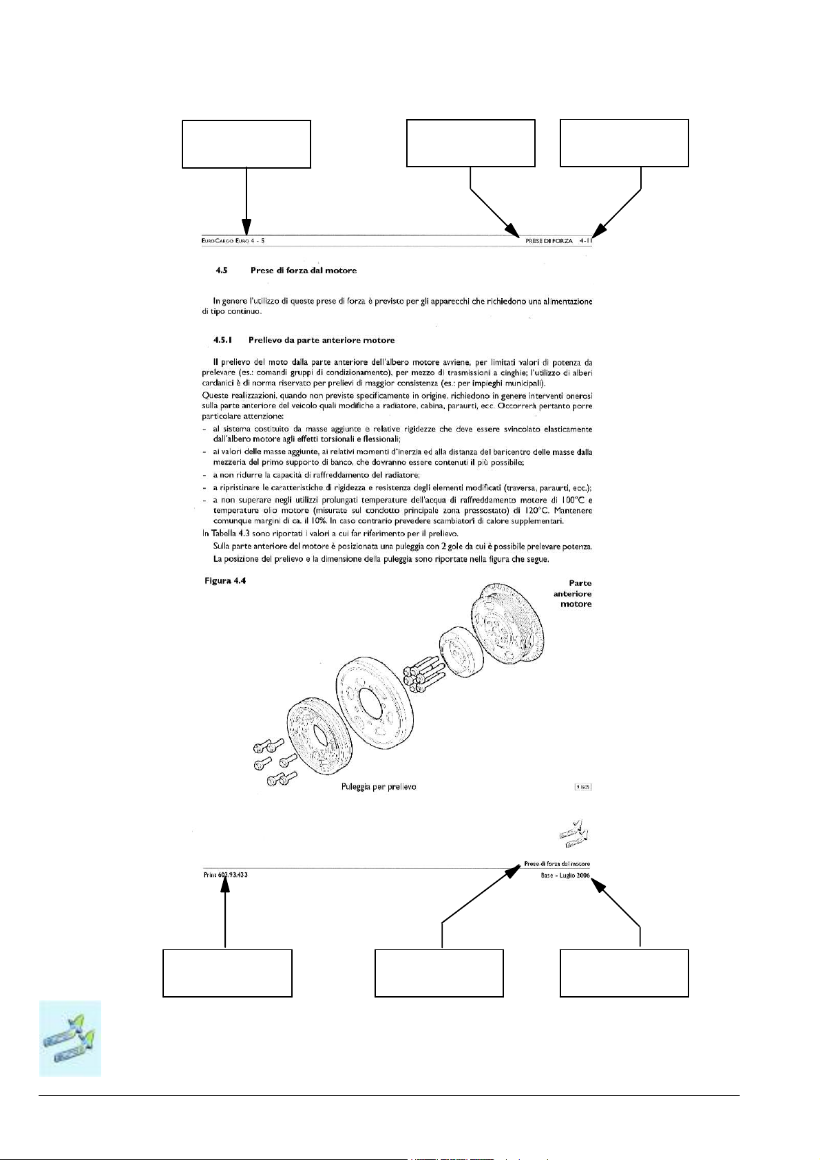
Figure 1.1 Vehicles with 2 axles; vehicles with 3 axles with an equal load on the two
rear axles
A = Rear axle or tandem mid axle
W = Payload + body
= Share of payload on front axle
W
1
= Shareof payload on rear axle (ortandem)
W
2
Figure 1.2
Example to determine the position of the centre of gravity of the payload plus body
= Distance of centre of gravity from
L
1
centre-line of rear axle
(or tandem centre-line)
L = Actual wheelbase
Vehicles with 3 or more axles with a constant mass distribution ratio on
the two rear axles. For these vehicles the ”ideal” values of the wheelbase
and centreline between the axles, resulting from mass distribution, is determined by the Manufacturer.
L1=
respectively L1=L-
W1⋅ L
W
W2⋅ L
W
Example to verify compliance of admitted weight on the axles
W = Payload + body
= Share of payload on front axle
W
1
W
= Share of payload on rear axles
2
= Share of payload on first rear axle
W
3
W
= Share of payload on second rear axle
4
= Distance of centre of gravity relative
L
1
calculated centreline
L = Calculated wheelbase (ideal)
L
= Calculated centreline (ideal)
2
A = Distance between rear axles
W
W
W
W
=
1
=Wx
2
3=W2
=
4
WxL
L
x
W2xL
A
1
(L - L1)
L
(A - L2)
A
2
Attention:
On vehicles with three or more axles, with a variable mass distribution
ratio o n the two re a r a xles depending on the lo a d , t he ”i d e a l” values of
wheelbase and centreline between the axles will have to be calc ula ted
on the basis of the information given in the chassis cab diagram, or in the
specific documentation specially prepared by IVECO. In this way, for
special versions (e.g . cranes on rear overhang) it will be possible todetermine the co r r e ct positioning of the cent r e of gravi t y of the equipment
and payload on the basis of the actual load (see point 5.4 in section 5).
Dimensions and weights
Base - January 2008 Print 603.93.721
Page 19
STRALIS AS/AT/AD Euro 4/5
GENERAL SPECIFICATIONS
1-11
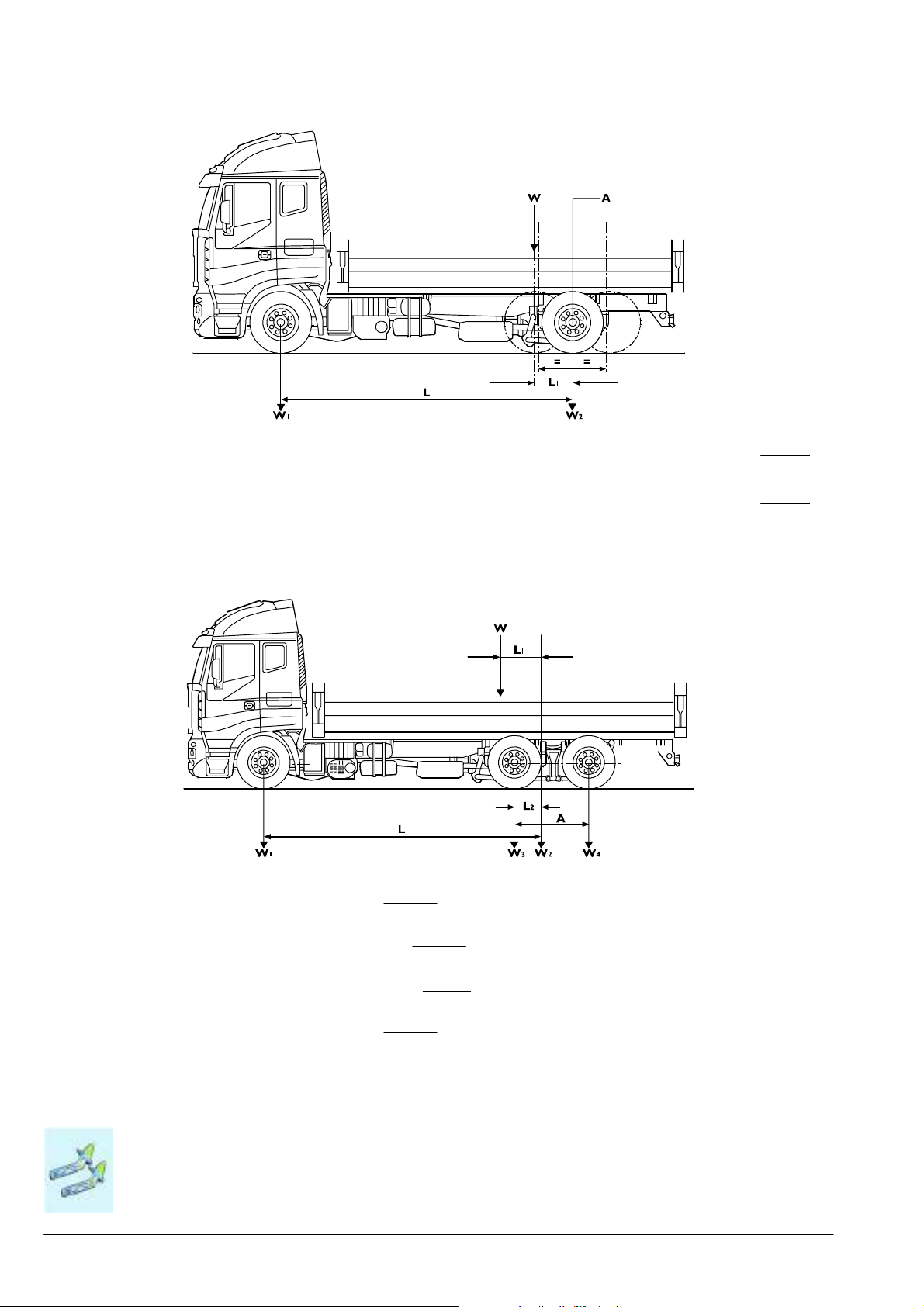
In order to apportion the payload on the axles, it must be uniformly distributed except when the shape of the loading surface itself
entails a different distribution of the load.
As for equipment, the actual location of the centre of gravity is used.
When building bodies or containers, loading and unloading systems for the transported goods must be devised which preclude ex-
cessive variations in the distribution of the load and/or excessive loads on the axles, also giving the relevant instructions to t he users.
The bodybuilder willalso need to installsu itable payload securing systemson the body sothat transport can be madewith the utmost
safety.
Figure 1.3
Uniform distribution of the load Non-uniform distribution of the load due to the
Uniform distribution of the load Non-uniform distribution of th e load (beware of load on axles
lack of rear overhang
and minimum ratio)
Dimensions and weights
Print 603.93.721 Base- January 2008
Page 20

1-12
GENERAL SPECIFICATIONS
S
TRALIS AS/AT/AD Euro 4/5
Height of the Centre of Gravity
The height of the centre of gravity of the chassis cab is given in the technical documentation specific to each model (chassis
drawing).
For testing the vehicle complete with superstructure, the bodybuilder must check that the height of the centre of gravity of the
equipment including the payload, or of the entire vehicle when fully loaded, falls within the maximum permitted values.
These limits are defined in compliance with the national or international regulations (e.g. as amended by the current EC braking
Directive) or requested by the Manufacturer to ensure good handling of the vehicle (e.g. transverse stability of the moving vehicle).
In order toc omply with the current ECDirective, IVECO providesinformation forthe various models (wheelbaseand specific body)
on computer, regarding:
- height of centre of gravity of chassis cab (e.g. chassis cab diagram, braking data);
- maximum height of centre of gravity of complete vehicle at full load (e.g. national type-approval document);
- braking capacity of each single axle (e.g. braking data).
Figure 1.4
Verification with full load:
Wv . Hv + Ws . Hs
Ht =
Wv = Chassis cab vehicle kerb weight
Hv = Height of centre of gravity of chassis cab vehicle (laden condition)
Ws = Body and payload
Hs = Height of centre of gravity of body and payload in relation to ground
Wt = Vehicle weight when fully loaded
Ht = Height of centre of gravity of vehicle fully laden to gvw
Wv + Ws
(Wv + Ws) . Ht − Wv . Hv
Hs =
Ws
To check the vehicle with its body but no payload, use above formula but for Ws use only the body kerb weight (The position for
Hv will depend on the load and deflection of the suspension).
The height of the centre of gravity indicated in Tabella 2.6 represents values which are not to be exceeded for each given equipment
level. These values have been calculated only in terms of the transverse stability of the vehicle and are applicable to a mid wheelbase.
Any other possible restrictive specification, e.g. braking regulation , shou ld be taken into consideration.
The values given in Tabella 2.6 refer to the superstructure with fixed payload. In versions where the payload tends to move on side
(e.g. suspended loads, fluid loads etc.) especially when turning, higher dynamic stress is generated which makes the vehicle less stable.
This must be taken int o consideration when providing vehicle operating instructions or for possible reduction in the height of the
centre of gravity.
Dimensions and weights
Base - January 2008 Print 603.93.721
Page 21

STRALIS AS/AT/AD Euro 4/5
GENERAL SPECIFICATIONS
1-13
Using Stabiliser Bars
Supplementary stabilising or anti-roll bars, where available, spring reinforcements or the application of rubber components (in
compliance with point 2.7) may increase the height of the centre of gravity of the payload which must be defined as each occasion
arises. The modification must be carried out after careful consideration has been given to the specifications of the version, to the
wheelbase and to the distribution of the cross-stresses act in g on the suspension both at the front and at the rear of the vehicle.
It must be borne in mind that it is often advisable to modify the rear axle only since a modified front axle would give th e driver a
false sense of stability making it more difficult to perceive the safety limits. Modification to the front axle may be made where the
load is positioned behind the cab (e.g. crane) or where the superstructures are very rigid (e.g. van conversion).
Exceeding the Limits
When transportinggoods with anexceptionally highcentre of gravity(e.g. machinery,indivisiblecargo etc.) froma technical point
of view it is possible to exceed the values indicated in the table provided that the steering system of the vehicle is suitably adapted
to this condition (e.g. reduced speed, gradual changes on the steering wheel, etc.).
1.13.3 Observing the Permitted Weights
All limitsindicated in our documentation must be adhered to. The load of the front axle is of particular importance undervarying
load conditions, in order to ensure the correct steering characteristics on road surfaces of all types.
Particular attention must th erefore be paid to vehicles with a weigh t which is concentrated on the rear overhang (e.g. cranes, tail-lifts,
centre axle trailers) and to vehicles with a short wheelbase and a high centre of gravity (e.g. silo vehicles, cement mixers).
When positioning the body and equipment, the loads must be correctly distributed transversally. For each wheel a variation in th e
rated load (1/2 of the axial load) of 4% is permitted (e.g. admitted load on axle: 10,000 kg load admitted on each wheel: 4,800 to
5,200 kg) provided that the tyres permit it, without impairing braking or driving stability.
For vehicles with an added rear lift axle it must be remembered that, with the axle in the raised position, the effective wheelbase
is reduced, whereas the rear overhang is increased. It is therefore advisable that the centre of gravity of the body and payload is
located in front of the centre line of the driving axle. In addition to this it is not advisableto equipa vehicle which has its load concentrated at the rear, with a lifting device.
Apart from different specifications for specific individual vehicles, the following may be taken to be the minimum values for the front
axle:
- 20% of the total vehicle weight with uniformly distributed loads
- 25% of the total vehicle weight for loads that are concentrated on the rear overhang.
The rear overhang of the body must be built in strict observance of the permitted axle loads, the limitations in length, the positioning
of the tow hook and of the underride guard stipulated by the relevant regulations and legal requirements.
Variations in the Permissible weight
Special exceptions to the maximum permissible weight may be granted for particular applications for which, however, precise
limitations regarding th e use will be imposed in addition to possible vehicle reinforcements.
Such exemptions, if they exceed the limits imposed by law, must be authorised by the Administrative Authority.
A reduction in admissible vehicle load (downrating) may require modifications on some parts, such as the suspension. In these cir-
cumstances, the necessary information may be supplied.
The request for authorisation must include:
- Vehicle type, wheelbase, identification number, designated use.
- Weight distribution on the axles (e.g. vehicles equipped with crane and body) including positions of the centre of gravity of th e
payload.
- Proposals concerning the reinforcement of the vehicle components where necessary.
Dimensions and weights
Print 603.93.721 Base- January 2008
Page 22
1-14
GENERAL SPECIFICATIONS
Instructionsforthe CorrectFunctioningofthe Partsof the Vehicle andAccessibilityforMaintenance
S
TRALIS AS/AT/AD Euro 4/5
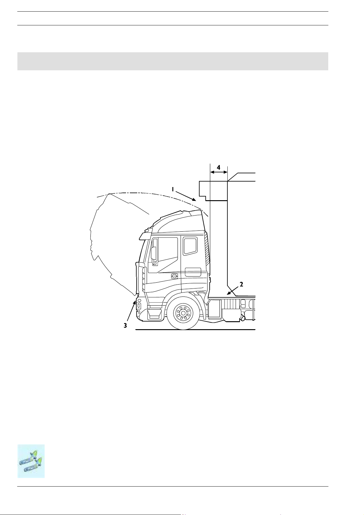
1.14 Instructions for the Correct Functioning of the Parts of the Vehicle and Accessibility for Maintenance
As a rule, when modifying or installing any type of equipment, nothing must be altered which prevents the correct fu n ctioning
of assemblies and parts of the vehicle under all operational conditions.
For example:
- Ready access to all parts requiring inspection or maintenance and periodic servicing must be provided. In the case of closed body
types suitable opening doors must be provided.
- For tilting cabs, adequate space permitting tilting must be assured. In the case of structures which involve the space above the
driver’s cab, adequate space for the passage of intake air must be guaranteed (see 1.5).
Figure 1.5
1. Retain adequate room for tilting the driver’s cab - 2. Retain thefreespaceabovethegearbox(fortractorswithsemitrailers
consider the movement between tractor and semitrailer) - 3. Cab pivot point - 4. Min. distance to be met
- Service access to chassis/driveline components must be retained. For instance repairing the gearbox or clutch must be possible
without necessitating the removal of major components of the added structure.
- The cooling system (radiator cowling, radiator, air passages, cooling circuit etc.), fuel supply (pump position, filters, pipe diameter,
etc.) and the engine air intake must not be altered.
- The anti-noise panels must not be altered or moved in order to prevent changes in the approved noise levels of the vehicle.
Should it be necessary to make openings (e.g. for the longitudinal runner of the body to pass through) these must be properly
closed off u sin g material with inflammability and sou ndproofing c haracteristics equivalent to those used originally.
Instructions for the Correct Functioning of the Parts of the Vehicle and Accessibility for Maintenance
Base - January 2008 Print 603.93.721
Page 23

STRALIS AS/AT/AD Euro 4/5
GENERAL SPECIFICATIONS
- Adequate ventilation of the brakes and battery case (especially in the case of box bodies) must be guaranteed.
1-15
- The positioning of the mud-guards and wheel-arches must allow free movement of the rear wheels even when chains are being
used. Sufficient space must also be ensured with lifting axles. Some of our models have 3
rd
axle steering which also steers in
the raised position; and it is necessary to leave space for this function (see point 2.20).
- When the vehicle has been set up, for safety reasons, headlight attitude must be checked and adjusted as necessary. Perform
the adjustment according to the instructions provided in the user and maintenance manual.
- In the c ase of parts which are supplied loose (e.g. spare wheel, chocks) it will be the responsibility of the bodybuilder to position
and secure them in an accessible and safe manner in compliance with possible national regulations.
1.15 Quality System management
For some time IVECO has been promoting Quality System development and trainin g for bodybuilders.
This is arequirement duen ot only to compliance with domestic andinternation al regulations on productliability, but alsothe growing
demand for increasingly higher quality levels. The creation of new forms of organization in the various sectors and the quest for
increasingly more advanced levels of efficiency.
IVECO believes it essential for bodybuilders to be equipped and organ ised where the following are defined and available:
- organization charts for functions and responsibilities.
- Quality System.
- quality goals.
- technical design documentation.
- process and control phases with relevant resources.
- product improvement plan, obtained also with corrective actions.
- after sales service.
- staff training.
- manufacturer liability documentation.
1.16 Vehicle maintenance
In addition t o making the necessary checks on the body/structure in keeping with customary working procedures, the bodybuil-
der shall perform the checks specified in th e “IVECO pre-delivery inspection” list, whic h can be obtained from the IVECO network,
for the aspects affected by the modifications performed.
Instructions for the Correct Functioning of the Parts of the Vehicle and Accessibility for Maintenance
Print 603.93.721 Base- January 2008
Page 24

1-16
GENERAL SPECIFICATIONS
Convention
S
TRALIS AS/AT/AD Euro 4/5
1.17 Conventions
In these bodybuilders instructions, the wheelbase is taken as the distance between the centreline of the first steering axle and
the centreline of the first rear axle (driven ornon-driven). This definition differs fromthe definition of wheelbase inthe CE Directives.
The rear overhang is taken as the distance between centreline of the lastaxle and the rear end ofthe chassisrunner. For dimensions
A, B and t of the frame and subframe section please refer to the figure below.
Figure 1.6
91473
Convention
Base - January 2008 Print 603.93.721
Page 25

STRALIS AS/AT/AD Euro 4/5
Index
CHASSIS MODIFICATIONS
SECTION 2
Chassis modifications
2.1 General instruct ions for chassis modifications 2-5
2.1.1 Specific Precautions 2-5
2.2 Painting and Rust Protection 2-7
2.2.1 Original components 2-7
2.2.2 Added or modified painted parts 2-9
2.2.3 Precautions 2-10
2.2.4 Max indicative height of center of gravity of payload in relation to transverse stability 2-11
2.3 Drilling t he Chassis 2-12
2-1
Page
2.3.1 Screws and nuts 2-12
2.3.2 Characteristics of the material to be u sed when modifying the chassis 2-13
2.3.3 Stresses on the chassis 2-14
2.3.4 Welding the Chassis 2-15
2.3.5 Closing of existing holes 2-17
2.4 Modifying the Wheelbase 2-18
2.4.1 General Specifications 2-18
2.4.2 Authorisation 2-18
2.4.3 Effects on the steering 2-18
2.4.4 Effects on braking 2-19
2.4.5 Recommended procedure 2-19
2.4.6 Chassis Stress Level 2-20
2.4.7 Cross Members 2-20
2.4.8 Changes to transmissions 2-20
2.5 Modifying the Rear Overhang 2-21
2.5.1 General Specifications 2-21
2.5.2 Reducing the Overhang 2-21
2.5.3 Increasing the Overhang 2-21
2.6 Installing a Towing Device 2-23
Index
Print 603.93.721 Base- January 2008
Page 26

2-2
CHASSIS MODIFICATIONS
S
TRALIS AS/AT/AD Euro 4/5
Page
2.6.1 General Specifications 2-23
2.6.2 Traditional towing hooks 2-24
2.6.3 Towhook for mid-axled trailers 2-25
2.6.4 Lowered Rear Cross Member 2-27
2.6.4.1 Centre axle trailers: towing cross member in lowered and forward positions (sh o rt coupling) 2-35
2.6.4.2 Reinforcement of Standard Rear Cross Member 2-35
2.6.4.3 Tow hooks for Centre Axle Trailers 2-37
2.6.4.4 Remarks about the Payload 2-37
2.6.4.5 Increasing the Towable weight 2-38
2.7 Installing a Supplementary Axle 2-38
2.7.1 General Specifications 2-38
2.7.2 Chassis Frame Reinforcement 2-38
2.7.3 Installing a Rear Supplementary Axle 2-40
2.7.4 Steering Axles 2-41
2.7.5 Components and Suspension 2-41
2.7.6 Stabilisers 2-41
2.7.7 Connection to the Chassis Frame 2-41
2.7.8 Braking system for additional axle 2-42
2.7.9 Raise Device 2-42
2.7.10 Modifying the suspension 2-45
2.8 Modifying the Drive Line 2-43
2.8.1 Permitted lengths 2-44
2.8.2 Determining Driveshaft Positions 2-46
2.9 Modifications of t he Engine Air Intake and Exhaust Syatem 2-49
2.9.1 Intake 2-49
2.9.2 Engine exhaust 2-49
2.10 Modification of the Engine Cooling System 2-50
2.11 Installation of a Supplementary Heating System 2-51
2.12 Installing an Air-Conditioning System 2-52
Index
Base - January 2008 Print 603.93.721
Page 27

STRALIS AS/AT/AD Euro 4/5
CHASSIS MODIFICATIONS
2-3
Page
2.13 Cab Modifications 2-53
2.13.1 General Specifications 2-53
2.13.2 Roof Panel Modifications 2-53
2.14 Changing the Size of the Tyres 2-54
2.15 Modifications to the Braking System 2-56
2.15.1 General Specifications 2-56
2.15.2 Brake Pipes 2-56
2.15.3 Electronic braking system control devices 2-61
2.15.4 Taking air from the system 2-61
2.16 Electrical System: Modifications and Drawing-Off Power 2-62
2.17 Repositioning Parts and Mounting Auxiliary Assemblies and Equipment 2-62
2.18 Transporting hazardous goods ADR 2-65
2.19 Retarder installation 2-67
2.20 Modifications to the Rear Underrun 2-68
2.21 Rear Mudguards and Wheel Boxes 2-69
2.22 Mudflaps 2-70
2.23 Side Guards 2.71
2.24 Chocks 2-73
Index
Print 603.93.721 Base- January 2008
Page 28

2-4
CHASSIS MODIFICATIONS
S
TRALIS AS/AT/AD Euro 4/5
Index
Base - January 2008 Print 603.93.721
Page 29
STRALIS AS/AT/AD Euro 4/5
2222.2
General i nstructi ons for chassis modi fications
CHASSIS MODIFICATIONS
2-5
2.1 General instructions for chassis modifications
Particular attention must be given to the following points:
- Welding to the bearing structures of the chassis is explicitly prohibited (with the exception of the items described at points
2.3.4, 2.4 e 2.5).
- Holes in the flanges of the side members are not permitted (except for the items described at point 3.4).
- Where riveted connections exist and can be modified as explained below, these can be replaced by flanged-head screws and
nuts of min. class 8.8 or by hex screws of the next greater diameter and self locking nuts. Screws greater than M14 must not
be used (max. diameter of hole 15 mm) unless otherwise specified.
- In cases where the original joints were detached and rejoined with bolts it is forbidden to reuse the same bolts. In this event
and when rivets are replaced with bolts, the bolt torque must be c hecked after the vehicle has been driven approximately 500
÷ 1.000 kms.
2.1.1 Specific Precautions
!
Figure 2.1
During welding, drilling, grinding and cutting operations near brake system pipes, and electrical cables, adopt the appropriate precautions for their protection. Remove them altogether
if necessary (observe the requirements set out under points 2.15.2 and 5.5).
91444
General instructions for chassis modifications
Print 603.93.721 Base- January 2008
Page 30

2-6
CHASSIS MODIFICATIONS
S
TRALIS AS/AT/AD Euro 4/5
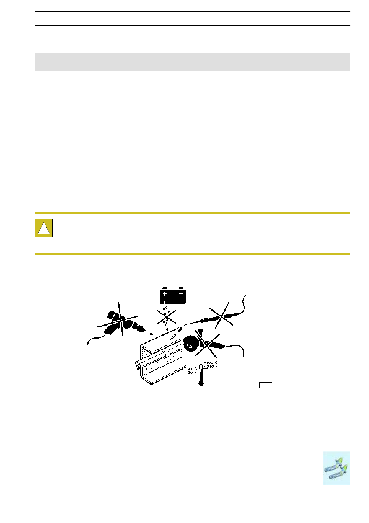
Take precautions concerning the alternator and the electrical/electronic components
In order to avoid damaging the diode rectifier, never disconnect the batteries (or open the isolator) when the engine is running.
If the vehicle has to be tow started make certain that the batteries are connected. Should it be necessary to charge the batteries,
disconnect them from the vehicle circuit.
In order to run the engine with external means and in order to avoid current peaks which might damage the electric/electronic
components, do not use the ”start” function in conjunction with external charge devices if such devices are equipped with this
function. Starting will have to be carried out only with the external battery trolley ensuring correct polarity.
Earth connections
As a general rule the original earth connections of the vehicle must not be changed. If it is necessary to move these connections
or to implement further earth points use the existing holes on the chassis as far as possible and:
- Remove, mechanically , and/or with an appropriate chemical product, the paint on the chassis side andon the terminal side creat-
ing a resting plane free from indentations or ridges.
- Apply appropriate high conductivity paint between the cable terminal and the metal surface (e.g. galvanizin g paint IVECO Part
number 459622 by PPG).
- Connect the earth cables within 5 minutes from the application of the paint.
Do not use the IVECO standardised M1 (battery earth connection) M2, M8 (earth connection for started motor depending on the
driving position) points for the earth connections for control switches (e.g. sensor or low absorption devices).
With regard to theelectronic devices, avoid linking earth connections between the devices; only use single wireearths with optimised
lengths (as short as possible).
Electric wiring
Stralis vehicles are equipped with an innovative electronic system called MUX. Before performing any
operation on the electrical system, read section 5 “Special instructions for electronic subsystems”.
!
For further information regar ding the braking and electronic system, refer to point 2.15 and 5.5.
List of technical guidelines and standards for correct installation of electrical cables in vehicle electron ic systems
Power cables (+ direct type) must be fed on their own into corrugated piping (of appropriate diameter) and not together with other
smaller cables (signal and negative cables); they must be spaced a minimum distance of 100 mm apart (reference value = 150 mm)
from high heat sources (engine turbine, exhaust manifold, etc., ...). and a distance of at least 50 mm must be maintained from chemical
agent containers (batteries, etc.).
This rule also applies to the area around moving parts.
Cables that run through perforated or angled panels must be protected by screw-on adaptors for cables (in addition to the corru-
gated pipe).
The corrugated pipe must wrap fully around the entire cable and must be secured with a heat-shrink sleeve or using adhesive tape
to the plastic terminal caps. Collars securing the corrugated pipe cut along their length must not deform the pipe, otherwise the
cables could be laid bare or come into contact with the sharp corners of the corrugated pipe.
All connection terminals (+) of the above cables and also their terminals must be covered with plastic caps waterproof version, at
all points exposed to atmospheric ingress or where water builds up.
The fastening of the terminal on the clamps (including the earth clamps) must be protected against accidental loosening. For this
reason, it is necessary to apply an appropriate tightening torque if possible. In the case of multiple terminal connections, these must
be in a star configuration (but this connection method should be avoided if possible).
The relevant cable route must be supported by fastenings and collars spaced close together to prevent hanging cables. After repair,
outfitting or conversion work, restore the wiring harness to its original condition.
When connecting the frame andthe tipper cab, check the wiring with the cab raised and tipped to detect and correct any abrasions
or tautness of the cables.
General instructions for chassis modifications
Base - January 2008 Print 603.93.721
Page 31

STRALIS AS/AT/AD Euro 4/5
tlyst
ructuralcharacter
ist
i
directlyvisibl
M
l
Typeof
p
(
)
(
)
y
A
lumini
Paintin gand R ust Protecti on
CHASSIS MODIFICATIONS
2-7
2.2 Painting and Rust Protection
2.2.1 Original components
Table 2.1shows the protection and painting classes required for original vehicle components. Table 2.2 shows classes forunpain-
ted or aluminium parts and Table 2.3 shows classes for painted parts.
Table 2.1 - Protection classes as for STD 18 - 1600 (Schedule I)
Class Features of the part Examplesofthetypeofpart
A Parts in direct contact with atmospheric agents Cab, rear view mirrors, cab fixing components
B
B1
C
Parts in direct contact with atmospheric agents with
mos
cs,
e
Parts in direct contact with atmospheric agents, not
directly visible
D Parts not in direct contact with atmospheric agents Pedals, seat frames, fixing components, internal cab pillars
Chassis and related parts, including fixing. Components
and parts under the hood
Rear and front axles
Engine and related parts
ateria
Stainless
steel
chemical coating
Ferrous
Zinc treatment
Anodizing yes yes yes yes
um
Painting yes - - -
(*) Hexavalent chromium-free
(1) I.S. 18-1101
(2) I.S. 18-1102
Table 2.2 - Various unpainted and/or aluminium parts and components
rotection
A B-B1 C D
Class
- yes - - -
FE/ZN 12 III
FE/ZN 12 IV (*)
DAC 500/8/PL
GEO 321/8/PL (*)
GEO 321/8/PM (*)
-
-
DAC 320/5
GEO 321/5 (*)
(1)
GEO 500/5 (*)
(1)
-
-
-
(2)
FE/ZN 12 V
FE/ZN 12 IV S (*)
-
-
yes
yes
-
-
-
yes yes
yes yes
- -
- -
-
-
-
Painting and Rust Protection
Print 603.93.721 Base- January 2008
Page 32

2-8
D
i
pti
p
h
g
(
g
Mechanicalsurfacecleaning(including
g
P
r
Anti-r
CHASSIS MODIFICATIONS
Table 2.3 - Painted parts as for STD 18 - 1600 (Schedule III)
S
TRALIS AS/AT/AD Euro 4/5
escr
Mechanical surface cleanin
on ofthecycle
includin
the removal of burrs / rust and cleaning
of modified parts)
ase
A B(5) B1 C D
Sand blasting - yes • - ye s • yes •
Brushing yes •
Sanding
Classes
Degreasing - - - yes • yes •
e-treatment
Phosphate degreasing
Phosphating of the heavy iron yes •
Phosphating of the zinc yes
High thickness (30-40 μm) yes (1) yes (4)•- yes (6)•yes •
Cataphoretic treatment
Low thickness (15-25 μm) yes (2)
Acrylic to finish (>35 μm) -
ust
Chip-resistant base
Bicomponent (30-40 μm) - yes (7) Monocomponent (30-40 μm) - yes
Mono (130 °C) or bicomponent (30-40
yes (2) - - - -
μm)
Mono (130 °C) or bicomponent (30-40
yes yes • - yes • yes •
μm)
Paint
Powders (50-60 μm) yes (3) yes
Monocomponentatlowtemperature
- - yes
(30-40 μm)
(1) = Cycle for two-coat preparation.
(2) = Cycle for three-coat preparation.
(3) = Alternative to the mono or bicomponent paint, only for cab parts (windscreen wipers, rear view mirrors, etc.)
(4) = Excluding parts that cannot beimmersed in pre-treatmentand paint baths, due to their geometry (air tanks), their large size (castings) or where this would
compromise their functionality (mechanical parts).
(5) = For ferrous steel or pre-coated fuel tanks, refer to Table 2.2.
(6) = Only parts fitted on the engine.
(7) = Parts that cannot be treated cataphoretically (4).
• = Alternative products and cycles for the same class, as long as they are compatible with the part being treated.
NOTE
All components installed on chassis must be painted as per Sta Iveco 18-1600 Colour IC444RAL 7021
brightness 70/80 gloss.
Painting and Rust Protection
Base - January 2008 Print 603.93.721
Page 33

STRALIS AS/AT/AD Euro 4/5
D
i
pti
p
h
Mechanicalsur
f
g(includ
ingther
f
bur
rs/
rust
g
r
ts)Brushing/sanding/sandblastin
g
M
l
Typeof
p
y
Fer
r
A
lumini
CHASSIS MODIFICATIONS
2-9
2.2.2 Added or modified painted parts
All parts of the vehicle (cab, chassis, bodywork, etc.) which are added or subjected to modification must be protected from rust
and corrosion.
There must be no unprotected areas on ferrous materials.
Table 2.4 (painted) and Table 2.5 (unpainted) show the minimum treatments required for modified or added components when
it is not possible to provide the same protection as that used on IVECO original components. Different treatments are allowed
on condition that the same level of protection against rust and corrosion is guaranteed.
Never use powder enamels directly after degreasing.
Parts in light alloy, brass and copper must not be protected.
Table 2.4 - Added or modified painted parts
escr
ace cleanin
and cleaningof modifiedpa
on ofthecycle
ase
emovalo
A-B-D(1)
Brushing/sanding/sand blastin
Pre-treatment Degreasing
Anti-rust Bicomponent (30-40μm) (2)
Paint Bicomponent (30-40μm) (3)
Class
(1) = Modifications to rear axles, front axles and engine (Classes B1 and C) are not allowed.
(2) = Preferably epoxy.
(3) = Preferably polyurethane.
Table 2.5 - Added or modified unpainted and/or aluminium parts
Class
ateria
rotection
A-B(1) D
Stainless steel
es
ous
chemical coating
Zinc treatment - yes
Anodizing yes yes
um
(1) = Modifications to rear axles, front axles and engine (Classes B1 and C) are not allowed.
Painting - -
-
-
Painting and Rust Protection
Print 603.93.721 Base- January 2008
Page 34

2-10
CHASSIS MODIFICATIONS
S
TRALIS AS/AT/AD Euro 4/5
2.2.3 Precautions
Suitable precautions must be taken to protect those parts whose preservation and operation could be damaged by paints such
as:
- rubber or plastic pipes for the air and hydraulic installations;
- gaskets, parts in rubber or plastic;
- flanges of the transmission shafts or power take-offs;
-radiators;
- shock absorber and hydraulic or air cylinder rods;
- drainage and bleeder valves (mechanical components, air tanks, cold starting heater plug pre-heating tanks etc.);
- fuel sediment filter;
- nameplates and logos.
With particular regard to the engine and its electric and electronic components, adequate precautions must be taken to protect:
- on the whole engine and vehicle wiring, including earth contacts;
- on all connectors on sensor/actuator side and wiring side;
- on all sensors/actuators, on flywheel, on flywheel rev sensor bracket;
- on the whole diesel fuel system pipes (plastic and metallic);
- on complete diesel fuel filter base;
- on control unit and control unit base;
- on the whole soundproofing cover inner side (injectors, rail, pipes);
- on common rail pump including regulator;
- on vehicle electric pump;
- on tank;
- on front belt circuit and relevant pulleys;
- on power steering pump and relevant piping;
- ECU’s fitted on the vehicle.
If the wheels are removed, protect the contact surfaces on the hubs, avoid increasing the thickness and especially avoid the build-up
of paint on the connecting flanges of the wheel disks and contact points of the fixing nuts.
Ensure that the disc brakes are adequately protected.
The electronic components and modules must be removed.
When the painting operation is to be completed by oven drying (max. temp. 80ºC), all parts which may
be damaged by exposure to heat, must be removed.
!
Painting and Rust Protection
Base - January 2008 Print 603.93.721
Page 35

STRALIS AS/AT/AD Euro 4/5
(
theground(mm)
CHASSIS MODIFICATIONS
2-11
2.2.4 Max indicative height of center of gravity of payload in relation to transverse stability
1)
Table 2.6
Base equipment
Max indicative height of center of gravity
includingbody or equipment)in relation to
Models
with anti roll bars
Front Rear
1 2 1 2
AS/AD/AT 190 x x 2720
AS/AD/AT 190/P x x 2750
AS/AD/AT 260 Y/TN x x 2740
AS/AD/AT 260 Y/P, Y/PS x x x 2720
AS/AD/AT 260Z/P x x x 2830
AS/AD/AT 260/P x x x 2720
Notes:
1) = Values refer to the transverse stability of the vehicle, to hold present eventual other limitations takes from the national and international regulations in
force (es. braking)
x = with standard anti-roll bar
- = without anti-roll bar
SW = to request roll bar
Painting and Rust Protection
Print 603.93.721 Base- January 2008
Page 36

2-12
CHASSIS MODIFICATIONS
DrillingtheChassis
S
TRALIS AS/AT/AD Euro 4/5
2.3 Drilling the Chassis
When it is necessary to mount assemblies or auxiliary units on the chassis, as a general rule,the existing holes made at the factory
should be used.
Under no circumstances should the flanges of the supporting member of the vehicle be drilled unless in compliance with
the indications given in point 3.3.1.
In those cases (installation of shelves, brackets etc.) where it is necessary to drill new holes, they must be drilled on the vertical
web of the side member and must be carefully deburred and reamed.
Position and Size
The new holes must not be made in areas of high stress (such as supports for springs) and at variance with the cross-section
ofthesidemember.
The diameter of the holes must be proportional to the thickness of the steel. Under no circumstances must this exceed 15 mm
unless otherwise specified. The distance from the centre of the hole to the edges of the side member must not be below 40 mm.
The centres of the holes must never be located at a distance of less than 45 mm from each other or in relation to the existing holes.
The holes must be staggered as shown in Figure 2.2. When moving spring support or crossmembers, the same drilling arrangement
must be u sed always maintain the original boring.
Figure 2.2
91445
2.3.1 Screws and nuts
In general, use connectors of the same type and class as those for similar fixings on the original vehicle (Table 2.7).
As a general rule, materials of class 8.8 are recommended. Class 8.8 and 10.9 screws must have been hardened and tempered. For
applications of diameter
in Table 2.2. A Dacromet finish is not recommended if the screws are to be subjected to welding. If space allows, use screws and
nuts with flanged heads. Use self-locking nuts. Nuts must be tightened using a torque wrench set to the correct torque setting for
the fixing.
± 6mm, stainless steel parts are recommended. Approved finishes are Dacromet and zinc coating, as detailed
Drilling the Chassis
Base - January 2008 Print 603.93.721
Page 37

STRALIS AS/AT/AD Euro 4/5
52036022%
Table 2.7 - Classes of resistance for screws
CHASSIS MODIFICATIONS
2-13
Class of resistance Usage
Tensile strength
(N/mm
2
)
Yield point
(N/mm
2
)
4 (1) Non-load bearing screws 400 320
5.8 (1) Low resistance screws 500 400
Medium resistance screws
8.8
(cross members, cleat plates,
800 640
brackets)
High resistance screws
10.9
(spring supports, anti-roll bars
1000 900
and shock absorbers)
(*) Do not use
2.3.2 Characteristics of the material to be used when modifying the chassis
When modifying the chassis of the vehicle, and in applications which reinforce the side members dire ctly, the material used must
correspond in quality (Table 2.8) and thickness (Table 2.9) to that of the original chassis.
Should it not be possible to source materials of the thickness indicated, the next greater thickness may be used (e.g. 1 mm instead
of 6.1 mm).
Table 2.8 - Material to be used to modify the chassis
Steel name
Tensile strength
(N/mm
2
)
Yield point
(N/mm
2
)
IVECO FeE490
Europe S500MC 610 490 19%
Germany QStE500TM
Alternatively, just for rear overhang extension.
IVECO Fe510D
Europe S355J2G3
Germany QSt52-3N
UK BS50D
A5 elongation
Drilling the Chassis
Print 603.93.721 Base- January 2008
Page 38

2-14
CHASSIS MODIFICATIONS
Table 2.9 - Chassis section dimension and thickness
S
TRALIS AS/AT/AD Euro 4/5
Model Wheelbase (mm)
AxBxt longitudinal pitch
section(See Figure 1.6)
AD/AT/AS 190 Up to 6300 289/199x80x6,7
AS260/FP/FS Up to 5100+1395 289/199x80x6,7
AS260 S/PT Only 5700, 6050 289x80x7.7
AS260 (6X4) 4500 289x80x7.7
IVECO recommends the following chassis extension pieces, available from theSpare PartDivision are used for chassis extensions.
2.3.3 Stresses on the chassis
Do not exceed the following stres s values under static conditions:
Table 2.10
Range Permitted static stress on the chassis (N/mm2) σ amm.
On road Off -road use
Stralis 150 100
When required by national regulations, the bodybuilder must check that the stress limits are not exceeded.
Welding activity will cause a deterioration in the characteristics of the material. There f o re , when checking the stresses in thermicall y -
modifie d zones, consider a reduction of app r ox. 15% of the resistance characteristi cs.
Drilling the Chassis
Base - January 2008 Print 603.93.721
Page 39

STRALIS AS/AT/AD Euro 4/5
CHASSIS MODIFICATIONS
2-15
2.3.4 Welding the Chassis
Welding operations must only be carried out by specialist, trained personnel, using suitable equipment
and in a perfectly workmanlike manner. Any intervention on the system not carried out as per instruc-
!
tions provided by IVECO or carried out by unskilled staff, might severely damage the on-board systems, thus adversely affecting vehicle operation safety and efficiency and causing damages not covered
by warranty.
Welding is permitted:
- When joining the sidemembers to extend or shorten the wheelbase or rear overhang.
- For the application of reinforcing L section flitch on a side member that is to be modified as detailed below (v. Figure 2.3).
Figure 2.3
When arc welding, the instructions below must be followed in order to protect electric units and ECUs:
- before disconnecting power cables, check to ensure all electrical items are switched off;
- where an electric switch is installed (battery isolation switch) wait for cycle end;
- disconnect negative power pole;
- disconnect positive power pole without connecting it to ground and DO NOT short circuit it with negative pole;
- disconnect ECUs connectors, carefully and do not touch ECU connector pins;
- when welding within the electronic control devices, disconnect them from the vehicle;
- connect welding machine ground directly to the part to be welded;
- protect plastic pipes against heat sources and remove, if nec essary;
- if welding near leaf springs or air springs protect against welding spatters;
- avoid electrode or gun contact with spring leaves;
91448
Drilling the Chassis
Print 603.93.721 Base- January 2008
Page 40

2-16
CHASSIS MODIFICATIONS
S
TRALIS AS/AT/AD Euro 4/5
Operations for welding preparation
As part of the procedure it will be necessary to remove the paint and deoxidise the parts of the chassis that are affected by the
welding operation as well as those partswhich may have to becovered by possible reinforcements. When work has been completed
the modified part must be protected with adequate rustproofing (see point 2.2.2).
a) Cut the side members with a diagonal or vertical cut. (We recommend that the diagonal cut be used particularlyfor the section
between the wheelbase) Cuts are not permitted in areas in which the profile of the side member as well as the chassis width
change or in those where there is a high concentration of stresses (e.g. spring brackets). The cuts must not be made through
the holes present in the side member (see Figure 2.4).
Figure 2.4
YES
YES
91446
b) On the inner side of the side member give the parts that are to be joined a V-sh aped chamfer of 60° along the entire length
to be welded (see Figure 2.5).
c) Arc weld in stretches using carefully dried basic electrodes. The recommended electrodes are:
For S 500 MC (FeE490: QStE 500TM)
Diameter of the electrode is 2.5 mm, current intensity approx. 90A (max. 40A for each millimetre of diameter of the electrode).
Using MIG-MAG welding use a welding rod with th e same characteristics as the material to be welded (diameter 1 to 1.2 mm).
Recommended welding rod: DIN 8559 - SG3 M2 5243
gas DIN 32526-M21 or DIN EN 439
If FeE490 is used at very low temperatures, we recommend:
PrEN 440 G7 AWS A 5.28 - ER 80S - Ni 1
gas DIN EN439-M21
Avoid current overloading. Welding must be free from marginal cuts and waste material.
d) Repeat the operation on the reverse side by welding as detailed in point c).
e) Allow th e side members to cool slowly and uniformly. Cooling by air, water or other means is not permitted.
f) Remove excess material resulting from the welding operations by grinding.
Drilling the Chassis
Base - January 2008 Print 603.93.721
Page 41

STRALIS AS/AT/AD Euro 4/5
CHASSIS MODIFICATIONS
2-17
Figure 2.5
91447
g) On the inner side reinforcing L-section flitches should be applied. These should be made of steel and have the same characteris-
tics as the steel used for the chassis. The minimum dimensions are given in Figure 2.3.
The reinforcements may only be fixed to the vertical web of the side member using welding beads, plug welds, bolts or rivets
(Huck rivets may also be used).
The cross-section and the length of the weld bead, the number and distribution of the plug welds, bolts or rivets must be adequate to transmit the bending and shearing moment of the section.
2.3.5 Closing of existing holes
If, when making new holes, the existing holes are found to be too close (see Figure 2.2) these may be closed up by welding. To
ensure the success of this operation the outer edge of the hole should be chamfered and copper plate used for the inner part.
For holes with a diameter of over 20 mm, chamfered plugs may be used, welded on both sides.
Drilling the Chassis
Print 603.93.721 Base- January 2008
Page 42

2-18
CHASSIS MODIFICATIONS
ModifyingtheWheelbase
S
TRALIS AS/AT/AD Euro 4/5
2.4 Modifying the Wheelbase
2.4.1 General Specifications
Any change to the wheelbase affecting the electrical circuits and/or entailing a relocation of the electrical/electronic components must be approved and performed according to the instructions provided
!
in chapter 5.
As a rule, for each vehicle, modification to the wheelbase must be carried out on the standard wheelbase above or closer to
the new wheelbase required.
The measurements given in th e written authorisations will apply in all cases particularly for extensions made to the longest stan dard
wheelbase.
Frame cutting must be performed according to the indications given at point 2.3.4. Whenever permitted by the body size, wheelbases
should bemade equal to those planned inour production. This enables theoriginal transmission shafts and previously definedcrossmember positions to be used.
When extending a wheelbase beyond the production longest planned, the vehicle used must have the longest production wheelbase
to ensure the correct thickness side members are used. Particular care must betaken to comply with thelimits set by national regulations particularly with regard to t he limits for overall dimensions (where specified). Use only material shown at point 2.3.2.
2.4.2 Authorisation
The alteration of the wheelbase for the 4x2 versions is permitted without specific approval by IVECO in the following cases:
- If the wheelbase is to be lengthened and the new value is still within the standard range of length with the same side member
section. These sizes are given in the specific technical documentation or in Table 2.8 and Table 2.9.
- If the wheelbase is to be shortened without falling below the standard minimum values established for each model.
Provided the chassis converter gives sufficient guarantees from the technological and control point of view (qualified personnel,
adequate operating processes, etc.).
For the 6x2 and 6x4 versions the wheelbase may only be modified following specific approval by IVECO.
Conversion must be carried out performed in compliance with these instructionsby making the necessarychanges and adjustments
and taking the appropriate precautions (e.g., determining whether ECU parameters need updating, rearranging the exhaust pipes,
ensuring compliance with specific load limits on the rear axle, etc.), by taking into due account the requirements specified for the
original wheelbase lengths.
2.4.3 Effects on the steering
Generally, lengthening the wheelbase has a negative effect on the steering.
Whenever national regulations require it, the limits on the overall dimensions must be observed as well as the limits concerning
the effort applied on the steering wheel and the relevant operation times (e.g. ECE - R 79/01 standard or current EC Directive).
Tables 2.11 contain, the wheelbase extension limits for the various models, with series drive, at max load admissible on front axle
and with tires admissible on vehicle.
Should vehicles withlonger wheelbase beneeded, forspecial applications, itwill be necessary to fitvarious devices aimedat improving
the steering characteristics such as a reduction in th e maximum permitted load on the fron t axle or the installation of wheels and
tyres with shorter kingpin offset values (Table 2.17).
The fitting of an additional pump and a dual circuit power steering unit, if not immediately available, will require authorisation and
must only be installed by an authorised workshop.
Modifying the Wheelbase
Base - January 2008 Print 603.93.721
Page 43

STRALIS AS/AT/AD Euro 4/5
CHASSIS MODIFICATIONS
2-19
2.4.4 Effect on braking
Generall y, shortening the wheelbase has a negative effect on braking characteristics.
Table 2.11 gives the wheelbase alteration limits. Ask an authorised IVECO dealer for the conditions (brake cylinder, minimum tare
settings see section, technically permitte d masses, tyres, height of centre of gravity) under which these values are permissibl e .
Table 2.11 - Maximum permitted wheelbase lengthening depending on the load on the front axle and tyre dimensions
(ECE - R79/01 regulation and EG/70/311)
Max wheelbase value
between 1st steering
axle and 1st driving
axle (mm)
Kingpin offset
(mm)
Steering wheel
dia. (mm)
Models
AS/AD/AT 190
Max. load on front axle
(observe tyre carrying
capacity)
8000 6050 120 470
(without CM)
AS/AD/AT 190/FP-CM 8000
8000
AS/AD/AT 260 Y/P, Y/FP
8000 6050 120 470
5700
6700
120
120
470
510
(without CM)
AS/AD/AT 260 Z/P - HM 8000 6050 120 470
AS/AD/AT 260 Y/FP -CM 8000
8000
AS/AD/AT 260 Y/PS, Y/FS
7500
7500
(with CM)
8000
4500
5100
5700
6050
5700
120
120
120
120
120
470
510
470
510
470
AS/AD/AT 440TX/P (E5) 7500/7500 3140 120 470
AS/AD/AT 260XP 7500/7500 3140 120 470
FortyretypeseeTable2.17.
2.4.5 Recommended procedure
To ensure the success of the conversion proceed as follows:
- Arrange the vehicle so that the chassis is perfectly level, using the appropriate stands.
- Disconnect the propeller shafts, the braking system pipes, the wiring harness and any equipment that might prevent the work
being carried out correctly.
- Identify the reference points on the chassis (e.g. pilot holes, suspension supports).
- Mark the reference points with a light lineof punch markson the top flangeon both side membersafter ensuringthat their joining
line is perfectly at right-angles to the longitudinal axis of the vehicle.
- When re-positioning the spring hanger brackets, identify the new position using the reference marks made previously.
Check that the new measurements are identical between the left and right sides. Differences no greater than 2 mm should
emerge from diagonal checking of the lengths less than 1,500 mm.
Unless another tool is available, make new holes by using the supports and gussets of th e cross members as a template.
Fix the supports and cross members with rivets or bolts. If using bolts, fix the supports by reaming the holes and using class 10.9
calibrated bolts with nuts equippedwith a device that preventsthem from working loose.When space permitsit use flanged-head
screws and nuts.
- If cutting the chassis, make a second line of reference points so that the area affected by the modification is included between
these and the previous points (in any event ensure a distance of not less than 1500 mm. measured when the work has been
completed). Inside these two reference lines make points to mark out the area of the cut then proceed as indicated in point
2.3.4.
Before welding, ensure that the side members, including any added portion, are perfectly aligned and take measurements on
both sides and diagonally to check, as previously described. Fit the reinforcements as instructed at point 2.3.4.
Modifying the Wheelbase
Print 603.93.721 Base- January 2008
Page 44
2-20
CHASSIS MODIFICATIONS
S
TRALIS AS/AT/AD Euro 4/5
Further indications
- Protect the surfaces from oxidation as described in point 2.2.2.
- Restore the electrical and braking systems as described in points 2.15 and 5.5.
- For changes to the drive line follow the instructions given in point 2.8.
2.4.6 Chassis Stress Level
When lengthening a wheelbase, in addition to local reinforcement on the side member joint, the bodybuilder must provide sufficient reinforcements to achieve the section moduli of the side member section no lower than that designed by IVECO for the same
wheelbase or for next size up. Alternatively, when permitted by local regulations, larger subframe sections can be used.
The body builder shall verify that such stress is not greater than the one of the chassis with the original wheelbase, by assuming an
evenly distributed load and the chassis being considered as a beam resting on the suspension supports. In any case, more restrictive
limits (if an y) set by the national standards shall be complied with.
When extending out from the longest original wheelbase the reinforcements must depend on the length of the extension, the type
of body built and the use to which the vehicle is to be put.
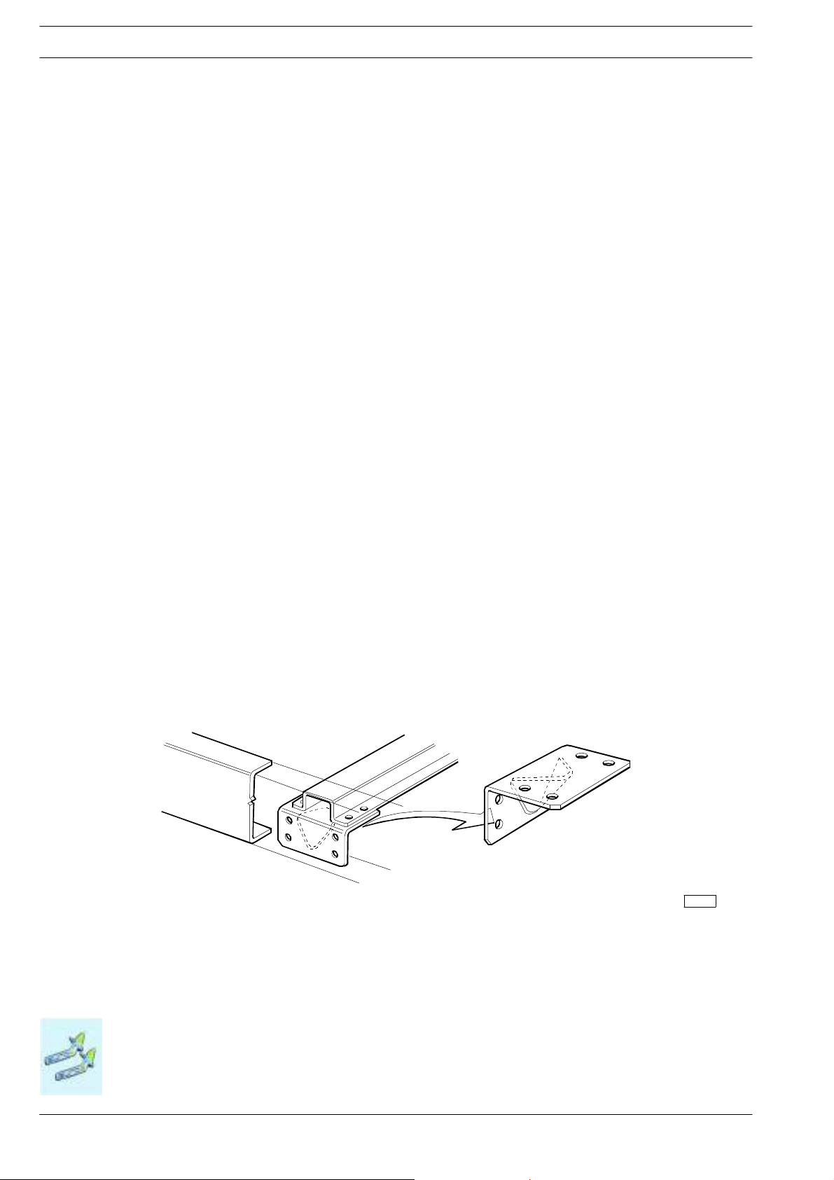
2.4.7 Cross Members
The necessity of applying one or more additional cross members depends on the length of the extension, the location of the
transmission shaft support, the welding area, the introduction points of the forces produced by the body and the condition under
which the vehicle is to be used .
Any supplementary cross membersmust have the samefeatures as those already existing (flexural strength, torsional strength, quality
of thematerial, connection to the side members,etc). In Figure 2.6 shows anexample of the application. A crossmember is mandatory for any extension over 600 mm.
As a general rule the distance between the two cross members must not be greater than 1000 to 1200 mm.
The minimum distance between two cross members must not be less than 600 mm, particularly for heavy-duty and off-road use;
this limit does no t apply to the ”lightweight” transmission support cross member.
Figure 2.6
91449
2.4.8 Changes to transmissions
See chapter 2.8 for admissible c hanges.
Modifying the Wheelbase
Base - January 2008 Print 603.93.721
Page 45

STRALIS AS/AT/AD Euro 4/5
ModifyingtheR earOverhang
CHASSIS MODIFICATIONS
2-21
2.5 Modifying the Rear Overhang
2.5.1 General Specifications
In modifying the rear overhang it must be borne in mind that such modification entails changes in the distribution of the payload
on the axles relative to the loads established by IVECO (see point 1.13). The limitations established by national laws must also be
respected as well as t he maximum distance from the rear edge of the body and the ground clearance prescribed for the tow hook
and the underrun bar.The distance fromthe extremity of thec hassis to the rear edge of the body must not, as a general rule,exceed
350 to 400 mm.
Should the bolted rear cross member be re-positioned, the same standard type of connections shou ld be maintained (i.e. number
of screws, dimensions, class of resistance).
When re-positioning rear cross members fastened by rivets, these can be replaced by flanged nuts and bolts with same diameter
or by class 8.8 hexagonal-headed screws with the next largest diameter. Use self-locking nuts (do not use bolts with a diameter
larger than M14).
When the installation of a tow hook is planned an adequate distance (approximately 350 mm) must be left from the rear cross
member to the next nearest cross member for mounting and removing the tow hook wherever necessary.
If the modifications are carried out competently and in compliance with the specifications contained in this manual, the towable
weight originally established may be retained. In any case responsibility for the work rests with those who have carried it ou t.
Authorisation
Authorisation from IVECO is not required, if the frame is extended at the rear, or is shortened to the minimum value admissible
for each model as stan dard, provided that this is done ac cording to the instructions given in this manual.
If it proves necessary modify the length of the electrical circuits, see chapter 5 “Special instructions for
electronic subsystems”.
!
2.5.2 Reducing the Overhang
If the rear overhang of the chassis has to be reshortened, the last cross member must be moved forward.
If, when reducing the overhang, the rear cross member is found to be too close to an existing cross member, the latter must be
removed if it does not affect the suspension supports.
2.5.3 Increasing the Overhang
Various methods of increasing the length are given in Figures, 2.7 and 2.8.
The framemay be straight cut. The minimum dimensions of the reinforcements the areto befitted to the modified section are given
in Figure 2.3.
Figure 2.7 shows a typical method of extension for increases of 300 to 350 mm. In this c ase the reinforcing L-bars, which also serve
to connectthe cross memberand the chassis frame,must beof the samethickness andwidth as theoriginal gussetplate. The connection of the cross member and theplates, originally achi eved with rivets, may be made with class 8.8bolts with the next largerdiameter.
Modifying the Rear Overhang
Print 603.93.721 Base- January 2008
Page 46

2-22
CHASSIS MODIFICATIONS
S
TRALIS AS/AT/AD Euro 4/5
In those cases where the joint between the cross member and the gusset plate is made by means of a weld, it is permissible to
join the gusset plate to the reinforcement by welding (see Figure 2.7).
When the increase exceeds 350 mm, Figure 2.8 shows the procedure to be used.
Figure 2.7
91454
1. Added portion - 2. Reinforcing runner - 3. Reinforcing runner (alternative solution) - 4. Original rear cross member
Figure 2.8
91455
1. Added portion - 2. Reinforcing runner - 3. Original rear cross member - 4. Supplementary cross member (if necessary)
So will be necessary to examine on a case by case basis, the feasibility of in stalling a supplementary cross member to give the frame
sufficient torsional rigidity. Adding a supplementary cross member with the same properties as the standard production cross member is necessary whenever the distance between two cross members is greater than 1200 mm.
Modifying the Rear Overhang
Base - January 2008 Print 603.93.721
Page 47

STRALIS AS/AT/AD Euro 4/5
InstallingaTowingDevice
CHASSIS MODIFICATIONS
2-23
2.6 Installing a Towing Device
2.6.1 General Specifications
Without prior authorisation, the installation of a tow-hook is permissible only on those cross members which are intended for
that use and on those vehicles which IVE CO has intended for towing a trailer.
The subsequent installation ofa tow hook in vehicles for which the installation of a tow hook was not originally contemplated, must
be authorised by IVECO.
In addition to the permissible towing weight, the authorisation will specify all other possible specifications that are to be adhered
to such as the use of the vehicle, the transmission ratio, the type of braking system as well as possible specifications concerning
reinforcements to be applied to the rear cross member or the necessity for employing specially intended cross members.
In trailers with one or more axles close together (centre axle trailers), considering the stress resulting in particular from the vertical
dynamic load to which the rear cross member is subjected, the instructions given in point 2.6.4 must be taken into account.
The tow hook must be appropriate for the permitted loads and of the type approved by national laws.
!
Since tow hooks are important to vehicle driving safety (in some countries they must be specifically
certified) they must not be modified in any way.
When mounting the tow hook to the cross member, the specifications of the h ook manufacturer as well as the limitations imposed
by current standards - such as minimum space required for the brake and electrical connections the maximum distance between
the swivel hook axis and the rear edge of the body - must be respected.
This may vary as a function of national standards. In the European Community a maximum of 420 mm can be reached. If higher
values are required, check the EC Directive for the conditions to be able to accomplish this.
Should the fixing holes in the flange of the coupling hook not match the holes in the rear towing crossmember of the vehicle then
in certain cases re-drilling may be authorised in specific cases after applying appropriate reinforcements.
It is the bodybuilder’s responsibility to ensure that no part of the body or structure creates a hazard or impairs the maneuverability
of the trailer.
The trailer drawbar must be free to move unobstructed.
Installing a Towing Device
Print 603.93.721 Base- January 2008
Page 48

2-24
gur
r
towing
CHASSIS MODIFICATIONS
2.6.2 Traditional towing hooks
Choice of hook for traditional trailers
The reference dimension for choosing the type of hook is defined by value D calculated as defined below.
e2.9
Fi
S
TRALIS AS/AT/AD Euro 4/5
116773
Free area fo
hooks
When selecting the appropriate hook and for the use of reinforcements for the rear cross member (where necessary), the effect
of thehorizontal forces producedby the weight ofthe tractor andtrailermust betaken into accountin accordancewith the following
formulas:
D = 9.81 x
TxR
T+R
D = Representative value of the hook class (kN).
T = Maximum weight of tractor, in t.
R = Maximum weight of trailer, in t.
Installing a Towing Device
Base - January 2008 Print 603.93.721
Page 49

STRALIS AS/AT/AD Euro 4/5
CHASSIS MODIFICATIONS
2-25
2.6.3 Towhook for mid-axled trailers
When using trailers with central axles or heavy single-axled trailers with enormous support loads (e.g. while braking or due to
vehicle vibration caused by road surface irregularities), the final crossmember is subject to additional twisting stress and the bending
moment on the protruding part of the frame is higher.
The towed load allowedfor this type of trailer is therefore lower than that of normal trailers with a steering drawbar (see table 2.12).
For vehicles with very protruding crossmember or mid-axled trailers with high towed loads, a frame installation section (see t able
2.12) that is sturdier than the one specified for this type of construction may have to be used.
On trailer with a fixed towbar, the installation frame must be fastened to the vehicle frame fromthe edge of the frame to the begin-
ning of the first rear axle suspension via the end blocks (replace consoles with end blocks or add more end blocks, see figure 2.12).
The towhook holes on the different towing terminalcrossmembers available for mostvehicles (for specific orders or as a conversion
product) correspond to a given attachment size.
For different towing terminal crossmembers, the towing loads shown in table 2.12 may generally be type approved for mid-axled
trailers provided the vehicle type is not subject to legal restrictions (e.g. engine power) or other construction u n its (e.g. transmission
unit, braking system).
For this reason, the values shown in table 2.12 must be confirmed in any case in writing by the frame manufacturer (e.g. in the type
approval certificates, in the manufacturer’s certification).
The value ofthe maximum (static + dynamic) verticalload transmitted by the trailer to the hook can be determined moreaccurately
through the following ISO formula:
2/l2
Fv = a · x
·C·0.6+S
Fv = Max vertical load (static + dynamic) transmitted by the trailer to the tow hook (kN)
a = Vertical acceleration in the drawbar/towing hook coupling area; depending on the rear suspension of the tractor for semi-
trailer, use the following values:
-a=1.8m/sec
2
for vehicles with pneumatic su spension (or equivalent)
-a=2.4m/sec2for vehicles with other suspension types
x = Total length in mms of the loading area of the trailer (m).
l = Length of the trailer wheelbase (distance between drawbar towing eye centre and axle centre or trailer axle centre line)
in m.
C = Total weight of trailer, R, minus the static load applied S (all values expressed in tons).
S = Static support load (kN).
0,6 = Deceleration factor.
Installing a Towing Device
Print 603.93.721 Base- January 2008
Page 50

2-26
Dimensionsofflange(mm
)
Maximumtowableweight(kg
)
(
)
CHASSIS MODIFICATIONS
Figure 2.10
Chassis reinforcement for centre axle trailers
S
TRALIS AS/AT/AD Euro 4/5
102183
1. Combined reinforcement - 2. Shear resistant connections (cleat plates) - 3. Subframe longitudinal runner -
4. Vertical load on tow hook
Table 2.12
Max. vertical loads permitted on hook
Dimensions of flange (mm)
(hook class)
Static S
(kg)
Total load *
(static+dynamic) Fv
Maximum towable weight (kg)
for centre-axle trailers R
120x55 (G135 or G3) 400 1130 4500
650 1690 6500
140x80 (G140 or G4) 900 2340 9000
G150 950 2470 9500
G5 1000 2960 12000
160x100 G6 1000 4040 18000
81 G5 1000 4400 20000
700G61 1000 5120 24000
* Indicative values determined according to ISO/TCC22/SCI5/WG4 Annex A through the following formula Fv = 3 × C × 0.6 + S (see following page)
Installing a Towing Device
Base - January 2008 Print 603.93.721
Page 51

STRALIS AS/AT/AD Euro 4/5
CHASSIS MODIFICATIONS
2-27
2.6.4 Lowered Rear Cross Member
If the typeof trailer used requires that thetow hook be positionedlower than originally intended, IVECO may issue authorisation
for the original cross member to be lowered or for an additional cross member (of the original type) to be fitted in a lower position.
Figures. 2.11 and 2.12 give some examples of how this is done.
The installation of the new cross member in its new position must be carried out in the same manner as before, using the same
type (diameter and class) of bolt.
Figure 2.11
91456
1. Original rear cross member - 2. Gusset - 3. Upside-down gusset - 4. Connecting angle piece
The thickness of the outer reinforcing angles must not be less than the thickness of the side members of the vehicle. They must
cover a length which is at least 2,5 times the height of the side member itself (maximum 600 mm) and be made of material with
the properties indicated in point 3.1.1. The angles are to be attached to the web of the side members using all the bolts joining the
cross member to the frame, integrating them with the other bolts so that, as a result of their number and location, they will take
into account the greater moment transmitted. As a general rule, when the cross member is lowered by an amount equivalent to
the height of the side member, the number of bolts is increased by about 40%.
When an additional cross member is installed (see Figure 2.12) a central joinin g plate with a thickn ess commensurate with that
of the cross members, must be employed.
A device to prevent the bolts from loosening must be adopted for t h e joints.
Installing a Towing Device
Print 603.93.721 Base- January 2008
Page 52

2-28
CHASSIS MODIFICATIONS
Figure 2.12
S
TRALIS AS/AT/AD Euro 4/5
Version for chassis with long overhangs
Version for chassis with short
overhangs
91457
1. Original rear cross member - 2. Connecting angle piece - 3. Connecting plate - 4. Gusset plate -
5. Pressed steel channel sections (same size as chassis) - 6. Space for rear sprung support
Assurance should be given that the movements between the tow bar and vehicle conform to current regulations. As a g eneral rule,
the original towable mass can be confirmed by IVECO. In any event th e responsibility for the work carried out will rest with the
bodybuilder.
The vehicle must be presented for inspection if local government regulations require it.
In Figure 2.12 shows an example of a lowered supplementary cross member.
When this solution is applied to short rear overhang vehicles, the external connecting plates must conform to the arrangement
described in Figure 2.12. Should the brackets of the underrun bar be modified, following the lowering of the rear cross member,
the new version will be equivalent to the original in terms of attachment, strength and stiffness and th e positioning of the lights
checked for compliance with t he standards (local standards where applicable).
Installing a Towing Device
Base - January 2008 Print 603.93.721
Page 53

STRALIS AS/AT/AD Euro 4/5
W
Model
s
Wheel
(mm)
(mm
)
ADAT190
ADAT190
Models
(Chassis section)
(mm)
,
115trear
289/199x80x6,7
13.0trear
289/199x80x6,7
CHASSIS MODIFICATIONS
2-29
Table 2.13 - Longitudinal runner profiles of the subframe for centre axle trailers
Towable weight (R) static load on towhook (S) to centre axle (kg)
heel
base
(mm)
3800 970 - - - - - - - - - - - - - - - 3800 1195 - - - - - - - - - - - - - - - 3800 1825 - - - - - - - - 46 - 46 - 46 - 46 4200 970 - - - - - - - - - - - - - - - 4200 1195 - - - - - - - - - - - - - - - 4200 2050 - - 46 - 46 - 46 - 46 46 46 46 46 46 46 46
4500 1780 - - - - 46 - 46 - 46 - 46 - 46 46 46 46
4800 2455 46 - 46 46 46 46 46 46 57 46 89 46 89 46 105 46
5100 1555 - - - - - - - - 46 - 46 - 46 - 46 5100 1960 46 - 46 - 46 - - 46 46 46 46 46 46 46 46 46
5100 2185 46 - 46 46 46 46 46 46 46 46 57 46 74 46 89 46
5100 2365 46 46 46 46 46 46 57 46 57 46 89 46 89 46 105 46
5500 2185 46 - 46 46 46 46 46 46 57 46 57 46 74 46 89 46
5700 2185 46 46 46 46 46 46 46 46 57 46 74 46 89 46 89 46
6300 2005 46 - 46 46 46 46 46 46 46 46 57 46 57 46 74 46
6300 2365 46 46 46 46 57 46 74 46 89 46 105 46 105 57 119 57
6300 2770 57 46 89 46 105 46 105 57 119 74 150 89 173 105 173 105
6700 3400 46 46 46 46 74 46 74 46 89 46 105 46 105 74 150 74
3800 970 - - - - - - - - - - - - - - - 3800 1195 - - - - - - - - - - - - - - - 3800 1825 46 - 46 - 46 46 46 46 46 46 46 46 46 46 57 46
4200 970 - - - - - - - - - - - - - - - 4200 1195 - - - - - - - - - - - - - - - 4200 2050 46 46 46 46 46 46 57 46 57 46 74 46 89 46 105 46
4500 1780 46 - 46 46 46 46 46 46 46 46 46 46 57 46 57 46
4800 2455 74 46 89 46 105 57 105 57 135 74 150 89 173 89 173 105
5100 1555 46 - 46 - 46 - 46 - 46 - 46 46 46 46 46 46
5100 1960 46 46 46 46 57 46 57 46 74 46 89 46 89 46 105 46
5100 2185 57 46 74 46 89 46 89 46 105 46 105 57 119 57 135 74
5100 2365 74 46 89 46 105 46 105 57 119 74 150 89 173 89 173 105
5500 2185 57 46 89 46 89 46 105 46 105 57 105 57 119 74 150 89
5700 2185 57 46 89 46 89 46 105 46 105 57 119 57 135 74 150 89
6300 2005 46 46 57 46 74 46 89 46 89 46 105 46 105 57 105 57
6300 2365 89 46 105 57 119 57 135 74 150 89 173 89 173 105 173 105
6300 2770 150 89 173 89 173 105 173 105 245 119 245 150 245 173 245 173
6700 3400 105 46 105 74 150 74 150 74 173 89 208 105 208 105 245 105
Max.
body
overhang
R≤ 9500
S≤ 950
Section modulus for each longitudinal section of subframe Wx (cm3) depending on the
240 360 240 360 240 360 240 360 240 360 240 360 240 360 240 360
R≤ 12000
S≤ 1000
R≤ 14000
S≤ 1000
S235 = ST 37 = FE 360 = 240 S355 = ST 52 = FE 510 = 360
R≤ 16000
S≤ 1000
material yield limit (N/mm
R≤ 18000
S≤ 1000
R≤ 20000
S≤ 1000
2
)
R≤ 22000
S≤ 1000
R≤ 24000
S≤ 1000
Installing a Towing Device
Print 603.93.721 Base- January 2008
Page 54

2-30
W
Model
s
Wheel
(mm)
(mm
)
5te
a
,
30tea
,
CHASSIS MODIFICATIONS
Models
(Chassis section)
(mm)
AS 190S /P,/FP,/FP-CM
11.5 t rear
289/199x80x6,7
AS 190S /P,/FP,/FP-CM
13.0 t rear
289/199x80x6,7
S
TRALIS AS/AT/AD Euro 4/5
Table 2.13 - (continued) Longitudinal runner profiles of the subframe for centre axle trailers
Towable weight (R) static load on towhook (S) to centre axle (kg)
heel
base
(mm)
3800 1847 - - 46 - 46 - 46 - 46 - 46 46 46 46 46 46
4200 1217 - - - - - - - - - - - - - - 46 4200 2072 46 - 46 - 46 46 46 46 46 46 46 46 46 46 57 46
4500 1307 - - - - - - - - 46 - 46 - 46 - 46 4500 1802 46 - 46 - 46 - 46 46 46 46 46 46 46 46 46 46
4800 2477 46 46 46 46 46 46 57 46 74 46 89 46 105 46 105 57
5100 1577 46 - 46 - 46 - 46 - 46 46 46 46 46 46 46 46
5100 1982 46 - 46 46 46 46 46 46 46 46 57 46 57 46 74 46
5100 2207 46 46 46 46 46 46 57 46 57 46 74 46 89 46 105 46
5100 2387 46 46 46 46 57 46 57 46 89 46 89 46 105 46 105 57
5500 2207 46 46 46 46 46 46 57 46 74 46 89 46 89 46 105 46
5700 1982 46 46 46 46 46 46 46 46 57 46 57 46 74 46 89 46
5700 2207 46 46 46 46 57 46 57 46 74 46 89 46 105 46 105 57
6300 2027 46 46 46 46 46 46 57 46 57 46 74 46 89 46 89 46
6300 2387 46 46 57 46 74 46 89 46 105 46 105 57 119 57 135 74
6300 2792 74 46 89 46 105 57 119 57 135 74 173 89 173 105 173 105
6700 3422 46 46 46 46 74 46 74 46 74 46 89 46 105 57 105 74
3800 1847 46 46 46 46 46 46 46 46 57 46 74 46 74 46 89 46
4200 1217 - - 46 - 46 - 46 - 46 - 46 - 46 - 46 46
4200 2072 46 46 57 46 74 46 89 46 89 46 105 46 105 57 119 57
4500 1307 46 - 46 - 46 - 46 - 46 46 46 46 46 46 46 46
4500 1802 46 46 46 46 57 46 57 46 74 46 89 46 89 46 105 46
4800 2477 89 46 105 57 119 57 135 74 150 89 173 89 173 105 173 105
5100 1577 46 46 46 46 46 46 46 46 46 46 57 46 57 46 74 46
5100 1982 57 46 74 46 89 46 89 46 105 46 105 57 105 57 119 74
5100 2207 89 46 89 46 105 46 105 57 119 74 135 74 173 89 173 89
5100 2387 89 46 105 57 119 57 135 74 150 89 173 89 173 105 173 105
5500 2207 89 46 105 46 105 57 119 57 135 74 150 89 173 89 173 105
5700 1982 57 46 89 46 89 46 105 46 105 57 105 57 119 57 135 74
5700 2207 89 46 105 46 105 57 119 57 135 74 150 89 173 89 173 105
6300 2027 74 46 89 46 105 46 105 57 105 57 119 74 135 74 150 89
6300 2387 105 57 119 74 135 89 173 89 173 105 173 105 173 105 208 119
6300 2792 173 89 173 105 173 105 173 119 245 135 245 150 245 173 245 173
6700 3422 89 46 105 57 105 74 150 74 150 74 173 89 208 105 208 105
Max.
body
overhang
R≤ 9500
S≤ 950
Section modulus for each longitudinal section of subframe Wx (cm3) depending on the
240 360 240 360 240 360 240 360 240 360 240 360 240 360 240 360
R≤ 12000
S≤ 1000
R≤ 14000
S≤ 1000
S235 = ST 37 = FE 360 = 240 S355 = ST 52 = FE 510 = 360
R≤ 16000
S≤ 1000
material yield limit (N/mm
R≤ 18000
S≤ 1000
R≤ 20000
S≤ 1000
2
)
R≤ 22000
S≤ 1000
R≤ 24000
S≤ 1000
Installing a Towing Device
Base - January 2008 Print 603.93.721
Page 55

STRALIS AS/AT/AD Euro 4/5
W
Model
s
Wheel
(mm)
(mm
)
AS260
S..Y/P
T
AS260
S..Y/P
T
AS260SY/P
T
T
N,/PTCTandGV
289/199x8
0x6,7
Table 2.13 - (continued) Longitudinal runner profiles of the subframe for centre axle trailers
Models
(Chassis section)
(mm)
19.0trear
289/199x80x6,7
20.0trear
289/199x80x6,7
21.0trear
289/199x80x6,7
AS/AD/AT 260 S
Y/P.., Y/FP
19.0 t rear
Invalid for versions /
CHASSIS MODIFICATIONS
Towable weight (R) static load on towhook (S) to centre axle (kg)
heel
base
(mm)
3805 1757 46 46 46 46 46 46 46 46 57 46 74 46 74 46 89 46
4200 2117 74 46 89 46 89 46 105 46 105 57 119 57 119 74 150 89
4500 2072 74 46 89 46 105 46 105 46 105 57 119 57 135 74 150 89
4800 1712 46 46 57 46 74 46 74 46 74 46 89 46 105 46 105 57
4800 2072 89 46 89 46 105 46 105 57 119 57 135 74 150 89 173 89
5100 1802 74 46 74 46 74 46 89 46 105 46 105 46 105 74 105 74
5700 2432 105 46 105 74 150 74 150 74 173 74 208 89 208 105 208 105
6050 2657 150 74 150 74 173 89 208 105 208 105 245 105 245 105 286 150
3805 1757 57 46 74 46 74 46 74 46 89 46 105 46 105 57 105 74
4200 2117 105 46 105 57 119 57 135 74 150 89 173 89 173 105 208 105
4500 2072 105 46 105 57 119 74 150 74 150 89 173 89 208 105 208 105
4800 1712 74 46 89 46 105 46 105 57 105 74 135 74 150 74 150 74
4800 2072 105 57 119 74 150 74 150 89 173 89 208 105 208 105 208 105
5100 1802 105 46 105 57 105 74 105 74 150 74 150 74 173 74 208 89
5700 2432 150 74 208 89 208 105 208 105 245 105 245 135 286 150 286 150
6050 2657 208 105 245 105 245 105 245 150 286 150 286 150 317 173 343 208
3805 1757 89 46 105 46 105 57 105 74 135 74 150 74 150 74 173 89
4200 2117 150 74 150 89 173 89 208 105 208 105 208 105 245 105 245 119
4500 2072 150 74 173 89 208 89 208 105 208 105 245 105 245 119 245 150
4800 1712 105 74 150 74 150 74 150 74 173 89 208 89 208 105 208 105
4800 2072 173 89 208 89 208 105 208 105 245 105 245 105 245 150 286 150
5100 1802 150 74 150 74 173 89 208 89 208 105 208 105 245 105 245 105
5700 2432 245 105 245 105 286 150 286 150 286 150 317 173 343 208 343 208
6050 2657 286 150 286 150 317 173 343 208 343 208 374 208 374 245 406 245
3120 722 46 - 46 - 46 - 46 - 46 - 46 - 46 - 46 46
3805 1757 105 46 105 57 119 57 119 74 150 89 173 89 173 105 173 105
4200 1127 46 46 57 46 57 46 57 46 74 46 89 46 89 46 89 46
4200 1622 105 46 105 57 119 57 119 74 150 89 173 89 173 89 173 105
4200 2117 150 89 173 89 173 105 173 105 208 119 245 135 245 150 245 173
4500 1217 57 46 74 46 74 46 89 46 89 46 105 46 105 57 105 57
4500 1622 105 57 105 57 119 74 135 89 173 89 173 89 173 105 173 105
4500 1802 119 57 135 89 173 89 173 89 173 105 173 105 173 105 208 119
4500 2072 173 89 173 105 173 105 173 105 208 119 245 135 245 150 245 173
4800 1487 105 46 105 57 105 57 119 74 135 74 150 89 173 89 173 105
4800 1712 119 57 135 74 150 89 173 89 173 105 173 105 173 105 208 119
4800 2072 173 105 173 105 173 105 208 119 245 135 245 150 245 173 245 173
5100 1802 150 89 173 89 173 105 173 105 173 105 173 119 245 119 245 135
5700 2432 105 46 105 74 150 74 150 74 173 74 208 89 208 105 208 105
6050 2657 150 74 150 74 173 89 208 105 208 105 245 105 245 105 286 150
Max.
body
overhang
R≤ 9500
S≤ 950
Section modulus for each longitudinal section of subframe Wx (cm3) depending on the
240 360 240 360 240 360 240 360 240 360 240 360 240 360 240 360
R≤ 12000
S≤ 1000
R≤ 14000
S≤ 1000
S235 = ST 37 = FE 360 = 240 S355 = ST 52 = FE 510 = 360
R≤ 16000
S≤ 1000
material yield limit (N/mm
R≤ 18000
S≤ 1000
R≤ 20000
S≤ 1000
2
)
R≤ 22000
S≤ 1000
2-31
R≤ 24000
S≤ 1000
Installing a Towing Device
Print 603.93.721 Base- January 2008
Page 56

2-32
W
Model
s
Wheel
(mm)
(mm
)
AS/AD/AT260
S
Y
T
N,/PTCTandGV
21t
289/199x8
0x6,7
AS/AD/AT260
S
Y
V
19t
289/199x8
0x7,7
CHASSIS MODIFICATIONS
Table 2.13 - (continued) Longitudinal runner profiles of the subframe for centre axle trailers
Models
(Chassis section)
(mm)
/P..,Y/FP
20 t rear
289/199x80x6,7
AS/AD/AT 260 S
Y/P.., Y/FP
Invalid for versions /
rear
/FP-G
onlywith CCM 11954
rear
S
TRALIS AS/AT/AD Euro 4/5
Towable weight (R) static load on towhook (S) to centre axle (kg)
heel
base
(mm)
3120 722 46 - 46 - 46 - 46 46 46 46 46 46 46 46 46 46
3805 1757 135 74 173 89 173 89 173 105 173 105 173 105 208 119 245 135
4200 1127 74 46 89 46 89 46 89 46 105 46 105 46 105 57 105 57
4200 1622 135 74 150 89 173 89 173 105 173 105 173 105 173 105 208 119
4200 2117 173 105 208 119 245 135 245 150 245 173 245 173 245 173 245 173
4500 1217 89 46 89 46 105 46 105 57 105 57 119 57 135 74 135 89
4500 1622 150 89 173 89 173 105 173 105 173 105 173 105 208 119 245 135
4500 1802 173 105 173 105 173 105 208 119 245 119 245 135 245 173 245 173
4500 2072 173 105 245 135 245 150 245 173 245 173 245 173 245 173 245 173
4800 1487 119 74 135 89 173 89 173 89 173 105 173 105 173 105 173 105
4800 1712 173 89 173 105 173 105 173 105 208 119 245 135 245 150 245 173
4800 2072 208 119 245 135 245 173 245 173 245 173 245 173 245 173 343 173
5100 1802 173 105 173 105 208 119 245 135 245 150 245 173 245 173 245 173
5700 2432 150 74 208 89 208 105 208 105 245 105 245 135 286 150 286 150
6050 2657 208 105 245 105 245 105 245 150 286 150 286 150 317 173 343 208
3120 722 46 46 46 46 46 46 46 46 46 46 46 46 46 46 46 46
3805 1757 173 105 173 105 173 119 245 119 245 135 245 150 245 173 245 173
4200 1127 89 46 105 46 105 57 105 57 119 57 119 74 135 74 150 89
4200 1622 173 105 173 105 173 105 208 119 245 119 245 135 245 150 245 173
4200 2117 245 173 245 173 245 173 245 173 245 173 343 208 343 245 374 245
4500 1217 105 57 105 57 119 74 135 74 150 89 173 89 173 89 173 105
4500 1622 173 105 173 105 173 119 208 119 245 135 245 150 245 173 245 173
4500 1802 208 119 245 135 245 150 245 173 245 173 245 173 245 173 245 173
4500 2072 245 173 245 173 245 173 245 173 245 173 343 208 343 245 374 245
4800 1487 173 89 173 105 173 105 173 105 173 119 208 119 245 135 245 150
4800 1712 173 105 245 119 245 135 245 150 245 173 245 173 245 173 245 173
4800 2072 245 173 245 173 245 173 245 173 343 208 343 245 374 245 374 245
5100 1802 245 135 245 150 245 173 245 173 245 173 245 173 245 173 317 173
5700 2432 245 105 245 105 286 150 286 150 286 150 317 173 343 208 343 208
6050 2657 286 150 286 150 317 173 343 208 343 208 374 208 374 245 406 245
4200 2117 105 - 105 - 105 - 150 - 150 74 173 74 208 89 208 105
4500 2072 105 - 105 - 135 - 150 74 150 74 173 89 208 105 208 105
4800 2072 105 - 105 - 150 - 150 74 173 89 208 105 208 105 208 105
5100 1802 89 - 105 - 105 - 135 - 150 - 150 74 173 74 208 89
5700 2432 173 89 208 105 208 105 245 105 245 150 286 150 286 173 317 173
- - - - - - - - - - - - - - - - - -
- - - - - - - - - - - - - - - - - -
- - - - - - - - - - - - - - - - - -
- - - - - - - - - - - - - - - - - -
- - - - - - - - - - - - - - - - - -
Max.
body
overhang
R≤ 9500
S≤ 950
Section modulus for each longitudinal section of subframe Wx (cm3) depending on the
240 360 240 360 240 360 240 360 240 360 240 360 240 360 240 360
R≤ 12000
S≤ 1000
R≤ 14000
S≤ 1000
S235 = ST 37 = FE 360 = 240 S355 = ST 52 = FE 510 = 360
R≤ 16000
S≤ 1000
material yield limit (N/mm
R≤ 18000
S≤ 1000
R≤ 20000
S≤ 1000
2
)
R≤ 22000
S≤ 1000
R≤ 24000
S≤ 1000
Installing a Towing Device
Base - January 2008 Print 603.93.721
Page 57

STRALIS AS/AT/AD Euro 4/5
W
Model
s
Wheel
(mm)
(mm
)
Y/FPG
V
onlywithCCM1195
4
AD/AT260S../TN
AD/AT260S../TN
CHASSIS MODIFICATIONS
Table 2.13 - (continued) Longitudinal runner profiles of the subframe for centre axle trailers
Towable weight (R) static load on towhook (S) to centre axle (kg)
Models
(Chassis section)
(mm)
AS/AD/AT 260 S 4800 2072 74 - 105 - 105 - 105 - 105 - 135 - 150 - 150 74
Y/FP-GV
only with CCM 11954
1200 towbar
19 t rear
289/199x80x7,7 - - - - - - - - - - - - - - - - - -
19.0trear
289x80x6,7
50:50 o 60:40
21.0 t rear
289x80x6,7
heel
base
(mm)
4200 2117 74 - 74 - 89 - 105 - 105 - 105 - 105 - 105 4500 2072 74 - 89 - 105 - 105 - 105 - 105 - 105 - 150 -
5100 1802 74 - 74 - 89 - 105 - 105 - 105 - 105 - 150 5700 2432 150 - 150 74 150 74 173 74 173 89 208 89 208 105 208 105
- - - - - - - - - - - - - - - - - -
- - - - - - - - - - - - - - - - - -
- - - - - - - - - - - - - - - - - -
- - - - - - - - - - - - - - - - - 3800 1765 46 46 46 46 57 46 74 46 74 46 74 46 89 46 105 46
4200 1630 46 46 46 46 57 46 74 46 74 46 74 46 74 46 89 46
4200 2125 74 46 89 46 105 46 105 57 105 74 150 74 150 74 150 74
4500 1630 46 46 46 46 57 46 74 46 74 46 74 46 89 46 105 46
4500 1810 57 46 74 46 74 46 74 46 89 46 105 46 105 57 105 74
4500 2080 74 46 89 46 105 46 150 57 105 74 150 74 150 74 173 89
4800 1495 46 46 46 46 46 46 57 46 74 46 74 46 74 46 74 46
4800 1720 57 46 74 46 74 46 74 46 89 46 105 46 105 46 105 57
4800 2080 74 46 105 46 105 57 105 74 150 74 150 74 150 74 173 89
5100 1810 74 46 74 46 74 46 89 46 105 46 105 57 105 74 150 74
5700 3025 245 105 245 150 286 150 286 173 317 208 343 208 374 208 406 245
6050 2665 208 89 208 105 245 105 245 150 286 150 286 150 317 173 343 208
3800 1765 74 46 74 46 74 46 89 46 105 46 105 57 105 74 135 74
4200 1630 74 46 74 46 74 46 89 46 89 46 105 46 105 57 105 74
4200 2125 105 57 105 74 150 74 150 74 173 89 208 89 208 105 208 105
4500 1630 74 46 74 46 74 46 89 46 105 46 105 46 105 57 105 74
4500 1810 74 46 105 46 105 46 105 57 105 74 150 74 150 74 150 74
4500 2080 105 57 135 74 150 74 150 74 173 89 208 105 208 105 245 105
4800 1495 57 46 74 46 74 46 74 46 74 46 89 46 105 46 105 46
4800 1720 74 46 89 46 105 46 105 57 105 74 105 74 150 74 150 74
4800 2080 105 74 150 74 150 74 173 89 208 89 208 105 208 105 245 105
5100 1810 89 46 105 46 105 57 105 74 150 74 150 74 150 74 173 89
5700 3025 286 150 343 208 343 208 374 245 406 245 406 245 406 286 474 286
6050 2665 245 135 286 150 286 173 317 208 343 208 374 208 374 245 406 245
6050 2665 317 208 343 208 374 208 374 245 406 245 406 245 406 286 474 286
Max.
body
overhang
R≤ 9500
S≤ 950
Section modulus for each longitudinal section of subframe Wx (cm3) depending on the
240 360 240 360 240 360 240 360 240 360 240 360 240 360 240 360
R≤ 12000
S≤ 1000
R≤ 14000
S≤ 1000
S235 = ST 37 = FE 360 = 240 S355 = ST 52 = FE 510 = 360
R≤ 16000
S≤ 1000
material yield limit (N/mm
R≤ 18000
S≤ 1000
R≤ 20000
S≤ 1000
2
)
R≤ 22000
S≤ 1000
R≤ 24000
S≤ 1000
2-33
Installing a Towing Device
Print 603.93.721 Base- January 2008
Page 58

2-34
W
Model
s
Wheel
(mm)
(mm
)
AD/AT260S../TN
AS260
S..X/P
AS260
S..X/P
AS260
S..X/P
90tea
00tea
0te
a
CHASSIS MODIFICATIONS
Models
(Chassis section)
(mm)
21.0trear
289x80x6,7
19.0trear
289x80x6,7
20.0trear
289x80x6,7
21.0trear
289x80x6,7
AS 260 S .. Z/P-HM
19.0 t rear
289x80x6,7
AS 260 S .. Z/P-HM
20.0 t rear
289x80x6,7
AS 260 S .. Z/P-HM
21.0 t rear
289x80x6,7
S
TRALIS AS/AT/AD Euro 4/5
Table 2.13 - (continued) Longitudinal runner profiles of the subframe for centre axle trailers
Towable weight (R) static load on towhook (S) to centre axle (kg)
heel
base
(mm)
3800 1765 89 46 105 46 105 57 105 74 150 74 150 74 150 74 173 89
4200 1630 89 46 105 46 105 46 105 57 105 74 150 74 150 74 150 74
4200 2125 150 74 173 89 205 105 208 105 245 105 245 105 245 150 286 150
4500 1630 89 46 105 46 105 57 105 74 105 74 150 74 150 74 150 74
4500 1810 105 57 105 74 150 74 150 74 173 74 208 89 208 105 208 105
4500 2080 150 74 208 89 208 105 208 105 245 105 245 105 245 150 286 150
4800 1495 74 46 74 46 89 46 105 46 105 46 105 57 105 74 135 74
4800 1720 105 57 105 74 105 74 150 74 150 74 150 74 173 89 208 105
4800 2080 173 89 208 105 208 105 245 105 245 105 245 135 286 150 286 150
5100 1810 105 74 150 74 150 74 173 74 173 89 208 105 208 105 208 105
5700 3025 374 245 406 245 406 286 474 286 474 286 SP 317 SP 343 SP 343
6050 2665 317 208 343 208 374 208 374 245 406 245 406 245 406 286 474 286
2840 2072 46 - 46 - 46 - 46 - 46 46 46 46 46 46 46 46
3140 1802 46 - 46 - 46 - 46 - 46 46 46 46 46 46 46 46
3440 2477 46 46 46 46 57 46 74 46 74 46 74 46 89 46 105 46
3740 2387 46 46 57 46 74 46 74 46 74 46 89 46 105 46 105 57
4340 2207 74 46 74 46 74 46 89 46 105 46 105 46 105 57 105 74
4690 2657 105 46 105 46 105 74 150 74 150 74 173 74 208 89 208 105
2840 2072 46 46 46 46 46 46 46 46 57 46 74 46 74 46 74 46
3140 1802 46 46 46 46 46 46 46 46 57 46 74 46 74 46 74 46
3440 2477 74 46 74 46 105 46 105 46 105 57 105 74 150 74 150 74
3740 2387 74 46 105 46 105 46 105 74 105 74 150 74 150 74 173 89
4340 2207 89 46 105 46 105 57 105 74 150 74 150 74 150 74 173 89
4690 2657 150 74 173 74 208 89 208 105 208 105 245 105 245 105 286 150
2840 2072 57 46 74 46 74 46 74 46 89 46 105 46 105 57 105 74
3140 1802 57 46 74 46 74 46 74 46 89 46 105 46 105 46 105 57
3440 2477 105 57 105 74 150 74 150 74 173 89 208 105 208 105 208 105
3740 2387 105 74 150 74 150 74 173 89 208 89 208 105 208 105 245 105
4340 2207 150 74 150 74 173 74 208 89 208 105 208 105 245 105 245 105
4690 2657 208 105 245 105 245 105 286 150 286 150 286 150 317 173 343 208
3800 1487 46 - 46 - 46 - 46 46 46 46 46 46 46 46 46 46
4200 1847 46 46 46 46 46 46 46 46 57 46 74 46 74 46 74 46
4500 1982 46 46 46 46 57 46 74 46 74 46 74 46 89 46 105 46
3800 1487 46 46 46 46 46 46 46 46 46 46 57 46 74 46 74 46
4200 1847 57 46 74 46 74 46 74 46 89 46 89 46 105 46 105 57
4500 1982 74 46 74 46 89 46 105 46 105 46 105 57 105 74 150 74
3800 1487 46 46 57 46 74 46 74 46 74 46 74 46 89 46 105 46
4200 1847 89 46 105 46 105 46 105 57 105 74 150 74 150 74 150 74
4500 1982 105 57 105 74 135 74 150 74 150 74 173 74 208 89 208 105
Max.
body
overhang
R≤ 9500
S≤ 950
Section modulus for each longitudinal section of subframe Wx (cm3) depending on the
240 360 240 360 240 360 240 360 240 360 240 360 240 360 240 360
R≤ 12000
S≤ 1000
R≤ 14000
S≤ 1000
S235 = ST 37 = FE 360 = 240 S355 = ST 52 = FE 510 = 360
R≤ 16000
S≤ 1000
material yield limit (N/mm
R≤ 18000
S≤ 1000
R≤ 20000
S≤ 1000
2
)
R≤ 22000
S≤ 1000
R≤ 24000
S≤ 1000
See Table 3.2 (section bar dimensions)NOTE
Installing a Towing Device
Base - January 2008 Print 603.93.721
Page 59

STRALIS AS/AT/AD Euro 4/5
L
V
0.5.L
0.5.L
0.8
L
0.85L
0.8.L
0.8
5.L
CHASSIS MODIFICATIONS
2-35
Table 2.14 - Combined section reinforcement runner profiles Table 3.4
A B CorD E F G
Material yield point (N/mm2) ≤ 320 ≤ 320 ≤ 240 ≤ 240 ≤ 360 ≤ 360
Max. runner profile height
40 60 100 120 100 120
reduction (mm):
Combined reinforcements length
:
:
L
H
Example: Combined section as an
alternative to the channel section
C250x80x8 (mm)
0.6.L
U
U
0.6.L
U
U
0.95L
U
U
210X80X8 190X80X8 150x80x8
+ straight
section
15x80
U
1.0.L
U
130x80x8
+ straight
section
15x80
U
0.95.L
U
150x80x8
+angle
section
U
1.0.L
U
130x80x8
+angle
section
Actual height reduction (mm): 40 52 85 97 92 104
The continuity of combined reinforcement runners can be interrupted only in special cases and is subject to authorisation. Similarly, when it is difficult to apply
an external reinforcing L section (items F and G Figure 3.4) - owing to the presence of suspension mountings or air spring connection brackets - and the recessing
to be performed could excessively reduce the section’s resisting capacity, the adopted solution will require special authorisation.
2.6.4.1 Centre axle trailers: towing cross member in lowered and forward positions (short coupling)
Vehicles designed to tow centre axle trailers for which a final cross member located in a lowered or forward position (next
to the rear suspension rear mountings or air springs) is evisaged, do not require particular chassis reinforcing devices. For the subframe, the runner profile dimensions indicated for the different types of equipmen t (e.g. see Table 3.4 standard bodies) will be sufficient. The bodybuilder will accurately work out the size and position of the chassis con nection structure (see point 2.6.3 and 2.6.4)
and make us e of a suitable cross member and an appropriate towing hook.
The tow hookposition will be such topermit any movementbetween vehicle andtrailer drawbar according to the variousconditions
of use, to comply with the required safety margins and the standards and legal regulations in force (where applicable). In these cases
the standard underrun bar cannot be used, and the bodybuilder will investigate the possible permitted changes from specifications
or the specific solutions to adopt (e.g. tilt type underrun bar).
2.6.4.2 Reinforcement of Standard Rear Cross Member
When it isnecessary to reinforce the standardcross memberan d when original cross membersare not available, the bodybuilder
will provide suitable reinforcements for which he shall be responsible.
These reinforcements may consist of C-sections mounted on the inside of the cross member. Care must be taken to ensure that
the connections between the cross member and the side members are also reinforced following the procedures recommended
below, whenever stronger enforcements are required:
1) The mounting of a channel section on the inside of the cross member and joining it to the vertical web of the side member
or to the following cross member of the chassis, if it is situated in close proximity, in compliance with the procedures illustrated
in Figure 2.13.
Installing a Towing Device
Print 603.93.721 Base- January 2008
Page 60

2-36
CHASSIS MODIFICATIONS
Figure 2.13
S
TRALIS AS/AT/AD Euro 4/5
91459
1. Original cross member - 2. Reinforcing rail - 3. Connec ting angle pieces or plates
2) Mounting a box section of suitable dimensions underneath the cross member, anchored at the extremities to the vertical web
of the side members and joined at the centre of the cross member as shown in Figure 2.14.
In vehicles having a short rear overhang and a subframe, the box section can be fitted within the subframe sections, above the
cross-member, and connected to it by means of a plate (as shown in Figure 2.12).
Should box-section assembly require modification to underrun bar plates the original requirements for fastening, resistance and stiffness must be met (comply with local government regulations if any).
Installing a Towing Device
Base - January 2008 Print 603.93.721
Page 61

STRALIS AS/AT/AD Euro 4/5
Figure 2.14
CHASSIS MODIFICATIONS
2-37
91460
1. Original rear c ross member - 2. Box section - 3. Connecting plate - 4. Ribbing plate
2.6.4.3 Tow hooks for Centre Axle Trailers
The use of centre axle trailers involues the use of tow hooks suitable for this purpose.
The values of the trailer loads and of the permissible vertical loads are contained in the technical documentation of the manufacturer
of the tow hook or on the production data plate (e.g. DIN 74051 and DIN 74052).
There are also tow hooks with special type approval, whose values are greater than the ones mention ed in the above s tandards.
These hooks may in any case be subjected to restrictions depending on t he trailers used (e.g. drawbar length). In addition this can
imply that the rear cross member should be further reinforced and a subframe runner of larger size be fitted.
2.6.4.4 Remarks about the Payload
It should be ascertained that the static drawbar load does not cause the allowable load on the rear axle or axles to be exceeded
and that the required minimum load acting on the front axle is adhered to see point 1.13.3.
2.6.4.5 Increasing the Towable weight
For those vehicles which IVECO regards as suitable for towing a trailer, a request may be submitted to evaluate the possibility
of authorising a towable weight exceeding that which is normally permitted.
Such authorisation will include the conditions that must be c o mplied with and, where necessary, specifications concerning modifica-
tions and work to be carried out on the vehicle.
These include possible reinforcements to the standard cross member (see Figure 2.13), the instructions for installing a reinforced cross
member when available, and those on the brake system to be made.
The tow hook must be suitable for the new use. Its connecting flange must match that of the cross member.
To fasten the cross member to the chassis frame, preferably use flanged head nuts and bolts o r hex head screws of minimum class
8.8. Use self-locking nuts.
Installing a Towing Device
Print 603.93.721 Base- January 2008
Page 62

2-38
CHASSIS MODIFICATIONS
InstallingaSupplementaryAxle
S
TRALIS AS/AT/AD Euro 4/5
2.7 Installing a Supplementary Axle
The installation of an additional axle has heavy repercussions on the vehicle systems; in particular, it
has a critical impact on the braking system, the compressed air system, the wiring harness and the
!
MUX interconnection systems.
Accordingly, the addition of an extra axle must be approved by IVECO and must be performed according to the instructions given in chapter 5 “Special instructions for electronic subsystems”.
2.7.1 General Specifications
On certain models IVECO may authorise, upon request, the installation of a supplementary axle and, consequently, an increase
in the total weight of the vehicle.
The modification must respect the weight limitations and the conditions imposed by IVECO as well as all other conditions that may
be imposed by national laws and such that are necessary to ensure the safety and proper functioning of the vehicle.
Diagrams of the installation procedure may be submitted for inspection. These proposals must indicate the parts necessary to con-
nect the axle to the chassis as well as the reinforcements to, and modifications of the chassis. It is also necessary to submit diagrams
showing the changes made to t he systems.
The specifications given in points 2.5 and 2.6 are to be followed for all modifications of the chassis.
In view of the increased stresses due to the increase in permissible load, and in consideration of the different phases of the dynamic
stressesin operation as a resultof the different reactions on the chassis when the axle is added,it is necessary to provide appropriate
reinforcements to the chassis.
These reinforcements must in all cases satisfy all provisions of local applicable laws. The chassis that has thus been modified must
not be subject to flexural stresses greater than those of the original chassis in the corresponding sections.
2.7.2 Chassis Frame Reinforcement
Figure 2.15 illu strates possible ways of modifying the chassis. The reinforcements must be continuous and must span the length
of the entire frame of the vehicle up to the driver’s cab. For their attachment to the side member - when using L-bars - class 8.8
reinforcement bolts must be used and theirdiameter and distribution must be suchto enable the section reinforcements toprovide
the required strength.
Installing a Supplementary Axle
Base - January 2008 Print 603.93.721
Page 63

STRALIS AS/AT/AD Euro 4/5
Figure 2.15
CHASSIS MODIFICATIONS
91461
2-39
1. Bracket - 2. Plate - 3. Screws, rivets or Ø 20 to 30 mm holes to be filled with welding
Where an auxiliary frame is required as reinforcement (see point 3.1), the body mounting brackets o n the chassis (if any) should
be used for the attachment. An alternative method of attachment is shown in point 3.1.2 and those that follow it.
We recommend using shear resistant connection in the area of the rear overhang up to approximately the mid wheelbase (or to
a point no closer than 2 m from the front axle) (see Figure 2.15).
The fitting of reinforcing plates directly onto the flanges of the side members,u sing holes filled with welded material is not permitted.
This is to avoid affecting the strength of the original sections caused by poor welding.
This procedure is only permitted in special cases with specific IVECO authorization wh en there are proven difficulties in subsequent
body applications.
It is possible to do without reinforcements on the frame if the static stress values in the Table 2.10 are not exceeded.
Any limitations, imposed by national regulations must be c omplied with.
Because of the deterioration of t h e material’s properties during the welding process, if the installation is unavoidable it is then advis-
able to assume a reduction of 15% in the strength of the material when checking the load-effects acting on the various sections
of the chassis.
As a general rule the thickness of the reinforcing plate must not exceed that of the flange of the original chassis.
The mounting must be carried out by skilledpersonnel and the bodybuilder will be responsible for any damage to the frame resulting
from poor workmanship.
Installing a Supplementary Axle
Print 603.93.721 Base- January 2008
Page 64

2-40
CHASSIS MODIFICATIONS
S
TRALIS AS/AT/AD Euro 4/5
2.7.3 Installing a Rear Supplementary Axle
The installation of a rear supplementary axle generally implies that the chassis overhang should be lengthened, the extension
must be carried out in compliance with the specifications given in point 2.5.3 relating to the modifications of the chassis, leaving the
reinforcements mentioned above unaffected.
When an additional axle is added to the overhang with a section depth smaller than the depth within the wheelbase area the adjustment of the section to give a higher value could be a solution towards reducing the stress arising from the conversion.
In Figure 2.16 shows an example of the installation of a rear axle with an extension of the rear overhang.
Figure 2.16
1. Added supplementary axle - 2. Extension to the overhang - 3. Reinforcements for the modification of the chassis -
4. Connections - 5. Reinforcing runner
Installing an Intermediate Supplementary Axle
The installation of anadditional axle in aforward (intermediate) position relative tothe driveaxle may requirea possiblereduction
in the rear overhang (see point 2.5.2) in order to obtain the proper distribution of the weights (see Figure 2.18).
Figure 2.17
123842
123841
1. Added supplementary axle - 2. Reinforcing runner - 3. Connections - 4. Reduction in the rear overhang
Installing a Supplementary Axle
Base - January 2008 Print 603.93.721
Page 65

STRALIS AS/AT/AD Euro 4/5
CHASSIS MODIFICATIONS
2-41
2.7.4 Steering Axles
Steering axles can be installed both intermediately and at the rear. They can be of the self-steering or force-steering types and
be designed and installed in such a way that the required dependability and road safety are guaranteed. The self-steering axle must
be fitted with a device controlled from the driver’s seat which will lock the axle in the straight position when reversing.
The installation of an axle whose force-steering is obtained by means of the original steering system of the vehicle requires specific
authorisation from IVECO in relation to the suitability of the original components for the conversion in question. In this case, it will
be necessary for diagrams of the supplementary sy stem to be submitted for our inspection.
2.7.5 Components and Suspension
Manufacturing quality of all components used (axle, suspension, braking units, systems etc) must be ensured in order to guarantee
driving safety and good vehicle operation.
Particular care and attention must be paid to the designing and construction of the suspension in consideration of its importance
for the proper performance and handling of the vehicle on the road.
The designed suspension may be either of the mechanical leaf-spring type, pneumatic with air actuated springs or of a mixed type.
Whatever type is used it must not negatively affect the handling characteristics of the vehicle and its components in terms of driving
quality, comfort, road holding, working angle of die transmission and its working space in the case of an intermediate supplementary
axle.
Where the additional axle has its own independent suspension, the suspension characteristics must be proportional to those of
the original rear suspension in relation to the static loads applied to the two axles.
2.7.6 Stabilisers
When pneumatic suspension is used for the added axle, depending on the solution adopted, it may be further necessary to fit
an antiroll bar in particular when a body with a high centre of gravity is used.
Similar measures must be adopted to ensure stability in relation to mixed type suspension on an additional rear axle.
2.7.7 Connection to the Chassis Frame
The connections of the added axle to the chassis must be such as to be able to withstand all longitudinal and transverse stress
forces without transmitting them to the drive axle.
At the points in which the forces are introduced (spring supports, air spring brackets etc.), appropriate cross members or suitable
frame reinforcements must be provided.
Ensure that t he added axle is at right angles and aligned properly in relation to th e longitudinal axis of the vehicle and the live axle.
Check using the appropriate equipment available in the market.
Installing a Supplementary Axle
Print 603.93.721 Base- January 2008
Page 66

2-42
CHASSIS MODIFICATIONS
S
TRALIS AS/AT/AD Euro 4/5
2.7.8 Braking system for additional axle
The braking system, considering its importance relative to the active safety of the vehicle, must be
extremely well developed and constructed.
!
Braking units, hoses and joints of the same type as on the original vehicle must be used.
The auxiliary axle must be equipped w ith the same brake components as those provided for the front axle.
Use flexible pipes to form the connection between the fixed parts (chassis) and moving parts (axles).
The braking torque must be proportional to the static and dynamic loads in order to provide an even distribution of the braking
action to all the axles of the vehicle.
The total braking c apacity of the modified vehicle must, as a general rule, be proportional to th at of th e original vehicle, allowing
for the different total mass that is now applicable. The performance of the braking system (service, emergency and parking) must
in all cases satisfy the current government regulations in terms of deceleration, behaviour when hot, response time, efficiency of
engine braking and so forth.
If the Technical Control Authority demands that the technical documentation regarding t he braking system be submitted (e.g. adhesion curves, compatibility range diagram) this must be provided by the company in charge of the conversion or the manufacturer
of the auxiliary axle.
Upon request, technicaldocumentation with characteristicsand attainable performances of the brakingsy stem of the original vehicle
may be made available.
For the construction of the braking circuit for the additional axle it is advisable to employ equipment and circuits specially provided
for each single model by the Manufacturer of the equipment in use on the original vehicles.
Solutions are allowed that include direct connection between the additional axle braking section and theengin e axle braking section.
Check that the air tank capacity is sufficient for the size of the new additional brake cylinders. If necessary, fit a supplementary air
tank.
Current legal requirements must be complied with for the emergency and parking brake. We recommend that a parking brake is
fitted on the additional axle.
For indications of a general nature concerning the braking system, see the instructions given at point
2.15.
!
For the electrical system, comply with the indications provided at point 5.5.
2.7.9 Raise Device
The additional axle may be equipped with a raise device and may also be used in specific cases where permitted by government
regulations, to increase the adhesion of the drive axle to the ground under certain conditions (starting uphill, slippery or snow/ice
covered roads) provided that:
- This modificationis made conditional tothe issue byIVECO of apermit in which the maximumpermitted loadon the overloaded
axle is specified.
- The device is used only for driving short distances for the uses stated above, and at the maximum speed stated on the specific
authorization.
Some nationalregulations permitthe use of the lifting device even during normal vehicle travel, providedthat the max. type-approval
load specified for the drive axle and admissible speed limits are not exceeded.
In such cases the indications given in point 1.13.2 should be heeded concerning the centre of gravity of the body plus the payload.
Approval of and Responsibility for the Operations Carried Out
Following conversion, the vehicle must be submitted to local authority technical control for approval (e.g.
single inspection or type approval).
The authorisation given by IVECO to install an auxiliary axle and th e passing of the approval inspection do not free the bodybuilder/
converter from responsibility for the conversion in question, or its effect on the vehicle.
For the added assemblies, the required service or maintenance operations with relevant schedule, consistent with the operations
and relevant schedule planned for the original vehicle must be defined and entered in the specific documentation.
Installing a Supplementary Axle
Base - January 2008 Print 603.93.721
Page 67

STRALIS AS/AT/AD Euro 4/5
InstallingaSupplementaryAxle
CHASSIS MODIFICATIONS
2-43
2.7.10 Modifying the suspension
Changes to the suspension can be made only with IVECO’s prior approval, the suspension being a system of decisive importance to riding safety.
!
As a general rule no modification of the parabolic springs is permitted. On vehicles equipped with these springs, installation of
elastic rubber components may be authorised for special versions or uses in order to increase the stiffness of the suspension. In
very specific cases, and for specific uses,t he possibility may be evaluatedof adding an extra leaf to the parabolic spring. Thisoperation
should be carried out by a specialised firm following approval by IVECO.
The use on the same axle of one parabolic spring and one trapezoidal spring is not allowed.
Installing a Supplementary Axle
Print 603.93.721 Base- January 2008
Page 68

2-44
CHASSIS MODIFICATIONS
ModifyingtheDr i veLine
S
TRALIS AS/AT/AD Euro 4/5
2.8 Modifying the Drive Line
Following the modification of th e wheelbase, work on the transmission as a general rule, is carried out on t h e basis of the transmission of a similar vehicle with approximately the same wheelbase. The maximum value of the inclinations of the propeller shafts
used for standard production vehicles is to be retained. This rule must also be applied when any modifications to the suspension
and rear drive axles are made.
In cases of particular difficulty, the assistance of the company may be sought. A diagram giving the length and inclination of the proposed n ew transmission must accompany the request.
The purpose of the specifications contained in this manual is to ensure the proper functioning of the transmission, to limit its noise
and to avoid the build-up of stress transmitted from the engine assembly.In no way does this diminish the responsibility of the bodybuilder for the work he has completed.
2.8.1 Permitted lengths
The maximum operating lengths obtainable for both the intermediate shaft sections and the sliding shafts ”LG” or ”LZ” (see
Figure 2.18) can be determined according to the external diameter of the tube existing on the vehicle and the maximum operating
rotational speed (see formula). These are specified in Table 2.15.
For the propeller shaft length specified in Table 2.15 when the tube diameter is not sufficient, a n ew shaft section with the same
characteristics as the existing sh afts must be used. As an alternative, in some c ases the transmission shaft with a larger diameter tube
can be used. The tu be diameter required can be determined in compliance with the required length and the maximum rotational
speed, directly from Table 2.16.
Figure 2.18
INTERMEDIATE SHAFT
CC
LZ
SINGLE-SECTION SHAFT
SLIDING SHAFT
LG
116721
Modifying the Drive Line
Base - January 2008 Print 603.93.721
Page 69

STRALIS AS/AT/AD Euro 4/5
Jointsize
)
CHASSIS MODIFICATIONS
2-45
As far as sliding shafts are concerned,length LG is measured between the universal joint centres,with the sliding stubin its intermediate position.
As regards single-stub shafts, check both branches LG and LZ.
The maximum working revs can be obtained using the formula below:
n
nG=
n
= maximum number of engine revolutions (rpm).
max
= gear ratio in fastest gear.
i
G
= transfer box ratio, equal to 1 if not present or for shafts upstream of the transfer box.
i
V
max
i
G
The maximum propeller shaft speed is determined on the basis of the following formula (the necessary data may be obtained from
the vehicle specifications and from the data plates on the engine, gearbox or transfer case).
n
max
i
G
n
= Max. prop. shaft speed (rpm).
g
= Max. engine speed (r.p.m.).
n
max
= Gearbox ratio at top speed.
i
G
nG=
The greater thic kness of the tube depends on the class, i.e. on th e torque that the original shaft has to transmit and on the design
of the driveline (torque, ratios of kinematic c hain, power axle load).
A reference value for the thickness of the tube of a general validity cannot be given. When, for example, a tube of a larger diameter
is to be used, its thickness should theoretically be reduced until the torsional strength of the original tube is achieved. It should
however be noted that, to determine the thickness of the tube, the following points are to be taken into account: the size of the
male element of the fork, the possible necessity of adapters and the sizes of the tubes available.
Therefore the th ickness of the tube should be agreed upon as each oc casion arises with the workshops authorised by the manufacturers of the transmission shaft depending on its dimensions (i.e. size of the universal joint).
The minimum operating length (from flange to flange) must not be less than 800 mm for the sliding sect i ons and 700 mm for t he
intermediate sections.
Table 2.15 - Obtainable propeller shaft characteristics
MaxachievablelengthsLGorLZ(mm)
Outer diameter x
thickness(mm
1800 1900 2000 2100 2200 2300 2400 2500
Maximum number of propeller
shaft revolutions (rpm)
2040 100 x 4.5 3400 3150 2900 2650 2450 2300 2100 1950
2040 120 x 3 4450 4100 3750 3400 3150 2900 2650 2450
2045 120 x 4 4450 4050 3700 3400 3100 2850 2650 2450
2055 120 x 6 4400 4000 3650 3350 3100 2850 2600 2400
2060 130 x 6 4650 4250 3900 3600 3300 3050 2800 2600
2065 142 x 6 5000 4600 4200 3900 3600 3300 3050 2850
Modifying the Drive Line
Print 603.93.721 Base- January 2008
Page 70

2-46
g
e
CHASSIS MODIFICATIONS
S
TRALIS AS/AT/AD Euro 4/5
The maximum possible lengths given above refer to the original shafts; plan for shorter lengths (-10%)
for shafts obtained for by modification.
!
2.8.2 Determining Driveshaft Positions
In the case of drive lines which consist of several shafts, the individual shafts must all be approximately of the same length. As
a general rule, the difference in length between a non sliding and a splined shaft (see Figure 2.19) must not exceed 600 mm. The
difference in length between the shafts must not be more than 400 mm. A margin of at least 25 mm must be left so that the sliding
joint can travel when the splined shaft is closed. When fully extended the shaft sliding sleeve should cover the splined stub for a
length that should be about twice the diameter of the splined stub itself.
When the required length of the drive line exceeds the permissible length, an additional driven shaft must be provided as illustrated
in Figure 2.19.
Figure 2.19
91451
1. Engine, clutch, gearbox axis - 2. Intermediate shaft (non sliding) - 3. Intermediate shaft support - 4. Propeller shaft with slidin
end - 5. Inclination of rear axle case (static load) - 6. Inclination of rear axle case (max. compression) - 7. Inclination of rear axl
case (unladen) - 8. Intermediate shaft and axle case axis must have the same inclination
Modifying the Drive Line
Base - January 2008 Print 603.93.721
Page 71

STRALIS AS/AT/AD Euro 4/5
CHASSIS MODIFICATIONS
2-47
The intermediate sh aft an d the inclin ation of the rear axle case must be aligned accurately.
The difference in their inclination relative to the engine-clutch-gearbox axis must not vary more than 1°. This can be achieved by
fitting wedges between the rear axle and the springs, or by adjusting the rear axle reaction bars. The inclination of the rear axle must
not exceed 5.5°
When, with a loaded vehicle, the rear axle flange is at a level which is lower th an that of the gearbox flange, care must be taken
to ensure thatthe inclination of the differential housing and ofthe driven shaft are greater than the inclinationof the engine-gearbox
axis. On the other h and, if, with a loaded vehicle, the rear axle flange is at a level which is higher than that of the gearbox flange,
the inclination of the differential housing and of the driven shaft must be less than the inclination of the engine-gearbox axis.
When lengthening the wheelbase is substantial, it may becomenecessary to fit a supplementary intermediate shaft as shown in Figure
2.20. In this case the same inclination must be maintained between the engine-gearbox axis, the second intermediate shaft and the
axis of the differential housing.
Figure2.20
91452
1. Engine, clutch, gearbox axis - 2. 1
5. Propeller shaft with splined end - 6. Inclination of rear axle case (static load) - 7. Inclination of rear axle case (max.
compression) - 8. Inclination of rear axle case (unladen) - 9. Gearbox, 2
st
intermediate shaft - 3. Intermediate shaft support - 4. 2ndintermediate shaft -
nd
intermediate shaft and rear axle case axis must have
same inclination.
Elastic supports must be fitted with the aid of supporting plates, at least 5 mm thick (see Figure 2.21), connected to cross-members
having the same characteristics as those specified by IVECO.
When reducing the wheelbase it is recommended that the intermediate shafts are removed if the length of the splined shaft is less
than approximately 800 mm.
Figure 2.21
91453
1. Intermediate shaft - 2. Support bracket - 3. Backing plate - 4. Support of intermediate shaft
If the drive line consists of a sin gle shaft the inclination of the axle housing must be the same as the inclination of the engine-gearbox
axis.
Modifying the Drive Line
Print 603.93.721 Base- January 2008
Page 72

2-48
CHASSIS MODIFICATIONS
S
TRALIS AS/AT/AD Euro 4/5
The same holds true also for vehicles with separate gearbox. In addition to this, as a general rule, the wheelbase of such vehicles
cannot be reduced beyond the measurement of the shorter wheelbase contemplated for standard production (tippers for example).
The use of original drive line parts from IVECO is recommended for these modifications however. Should this not be possible, har-
2
dened steel tubes with a yield point of not less than 420 N/mm
(42 kg/mm2)maybeused.
Modifications to the universal joints are not permitted.
Whenever the transmission or part thereof, is modified, each modified section must be subjected to careful dynamic balancing.
Since transmission is important to vehicle driving safety, it should be borne in mind that any
modification to it must bear maximum operational guarantees. Only very specialised and transmission
!
manufacturer-certified companies should therefore be employed to carry out work of this kind.
IVECO’s approval is not required, if the frame is extended at the rear, or is shortened to the minimum value admissible for each
model as standard, provided that this is done according to the instructions given herein.
If it proves necessary modify the length of the electrical circuits, see chapter 5 “Special instructions
for electronic subsystems”.
!
Modifying the Drive Line
Base - January 2008 Print 603.93.721
Page 73

STRALIS AS/AT/AD Euro 4/5
Modifi cations of the Engi ne Air Intake and Ex haust Syatem
CHASSIS MODIFICATIONS
2.9 Modifications of the Engine Air Intake and Exhaust System
2.9.1 Intake
The specifications of the engine air intake and exhaust systems must not be altered without prior authorisation from IVECO.
Modifications carried out must not alter the vacuum levels (for t he intake) or the original exhaust back pressure levels.
Table2.16-EngineBackPressures
2-49
Engines Engine Code
Maximum exhaust back
pressure (kPa)
Maximum intake back
pressure (kPa)
CURSOR 8
E31 F2BE3681C
E33 F2BE3681B 20 6.5
E36 F2BE3681A
CURSOR 10
E42 F3A3681B
E45 F3A3681A 19 6.5
E46 F3A3681Y
CURSOR 13
E41 F3B3681D
E44 F3B3681G
E45 F3B3681C
E48 F3B3681F 28 6.5
E50 F3B3681B
E52 F3B3681E
E56 F3B3681A
The air intake must be positioned to avoid the intake of hot air from the engine and/or dusty air snow or rain. The apertures for
the intake of air which may have to be made in the side of integral bodies, must have a working surface of not less than two and
a half times that of the masterh ose located upstream of the filter. Theseapertures (e.g openings in the grill) must be of such a dimension that they do not become obstructed. It is prohibited to alter the air filer or replace the original filter with a lower air capacity
unit. Any connectionson the intake duct must guarantee resistance of the tube to penetration by water or dust andfree from sharp/
rough edges (or welding burrs inside metal tube). It is not permissible to modify or substitute the original air filter.
2.9.2 Engine exhaust
The routing of the exhaust pipe must be as even as possible. Bends must not have an angle of less than 90º and the radii sho uld
not be less than 2.5 times the external diameter. Avoid kinks and usecross-sections which are no smaller than those corresponding
to the original system. Any connections on the intake duct must guarantee resistance of the tube to penetration by water or dust
and absence of sharp edges or welding burrs inside the tube. Su fficient clearance should be maintained (min. 150 mm) between
the exhaust pipe and the electrical system, plastic hoses, the spare wheel, the plastic fuel tank (min. 100 mm), etc. Lower values
(e.g. 80 mm) may be permitted if suitable sheet metal shielding is used. Further reductions require the use of heat insulation and
the substitution of the plastic tubes with steel pipes. It is not permissible to modify or substitute the original air filter; the silencer
body cannot bealtered. Modificationsto the silencer bodyand engine equipment (injectors, enginecontrol unit etc.) are not permissible as this may alter the correct fun ctioning of the engine and adversely affect the emissions of gases from the exhaust.
Chapter 6 concerning SCR contains additional information on exhaust system changes.NOTE
Modifications of the Engine Air Intake and Exhaust Syatem
Print 603.93.721 Base- January 2008
Page 74

2-50
CHASSIS MODIFICATIONS
Modificati onof the En gine Cooling Syste m
S
TRALIS AS/AT/AD Euro 4/5
2.10 Modification of the Engine Cooling System
The properfunctionin g of the original system,especially in connection with the radiator, the freesurface of the radiator andhoses
(dimensions and layout) must n ot be tampered with. Whenevermodifications must be made that entail work on th e engine cooling
system (e.g., modifications to the cab), the following points must be considered:
- The useful area for the passage of air for the cooling of the radiator must not be less than that which is available on vehicles
with the standard cab.Maximum venting of air fromthe engine compartment must be ensuredand care must be taken - possibly
using shields or baffles - to avoid stagnant air pockets or back flow of air. The performance of the fan must not be altered.
- If it is necessary to re-position the hoses this must be done without affecting the complete filling of the system (which must occur
at a continuous flow without forming blockages at the mouth) orth e normal flow of water. The maximum stabilising temperature
of the water must not be altered even under the most severe operating conditions.
- Hoses must be located so that air pockets are not formed (i.e avoiding air traps and providing appropriate bleeding points) that
could hinder the circulation of water. Check that the water pump primes immediately on starting the engine and later operates
with the engine idling (accelerate a few times, if necessary) even when the circuit is not pressurized. Check that the delivery
pressure of the water pump, when the engine is running under no load and at maximum RPM, is not lower than 1 bar.
- Always reinstall the radiator anti-clogging protection after making alterations to the engine cooling system.
Modification of the Engine Cooling System
Base - January 2008 Print 603.93.721
Page 75

STRALIS AS/AT/AD Euro 4/5
Install ation of a Supple mentary He ating System
CHASSIS MODIFICATIONS
2-51
2.11 Installation of a Supplementary Heating System
When the installation of a supplementary heating system is deemed necessary, it is advisable to use the types recommended
by IVECO.
For vehicles on which IVECO has not planned the use of suppleme nta ry heaters, the installation should be carried out in compliance
with the supplier’s instructions (i.e. heater arrangeme nt, piping, electrical system etc.) and following the directions given below.
All national rules and regulations relevant to the matter should be adhered to (i.e. inspections, particular installation for dangerous
cargo transporta tio n etc.). The suppleme ntar y heating system must not make use of the equipment that is specific to the vehicle
which is subject to approval if the use is liable to impair or alter the performance of the equipment.
Furthermore:
- ensure correct operation of the vehicle components and equipment (i.e. cooling system);
- check the electrical system to ensure that the battery capacity and alternator output is sufficient for the higher current requirements (see point 5.5). Provide the new circuitry with a protection fuse;
- connect the intake of the newly added fuel system to the reservoir connected to the engine fuel return line. Direct feed from
the vehiclefuel tank is permitted only ifthis is independent from theengine fuel systemand the new circuit is perfectly leakproof;
- trace pipe and cable paths, the location of brackets and hoses bearing in mind that the overall dimensions and heat affect the
various units on the chassis. Avoid runs and arrangements that could lead to hazards when the vehicle is running. Use shields
or armouring if necessary;
- When installing a water heater, original vehicle heating and engine cooling circuits are involved (see point 2.10), it is advisable
to follow the instructions listed below to ensure reliability of the heating system an d safe operation of the original system:
- special care must be taken when defining the connections between the supplementary equipment and the main one; refer
to IVECO, if necessary;
- determine a rational arrangement for piping, avoid neckings and siphonings;
- install proper ventin g valve (bleeding points) to ensure proper filling of the system;
- supplementary plugs should be installed to ensure draining of the system, if necessary;
- proper insulation should be used to prevent heat dissipation.
- When air heaters are u sed and when the installation is to be made directly in the cab, make sure that the engine exhaust system
does not touc h the added installation (to prevent exhaust gas circulation ins ide the vehicle) and have the correct warm air
distribution by avoiding direct air flows;
- the complete installation should be designed to ensure good accessibility for quick and easy servicing.
Installation of a Supplementary Heating System
Print 603.93.721 Base- January 2008
Page 76

2-52
CHASSIS MODIFICATIONS
InstallinganAir---ConditioningSystem
S
TRALIS AS/AT/AD Euro 4/5
2.12 Installing an Air-Conditioning System
When the installation ofan air conditioning system is deemednecessary, itis advisableto use the typesrecommendedby IVECO.
If this procedure is not applicable, the installation must be carriedout in accordance with the supplier’s instructions and the following
points:
- the installation must not interfere with the correct operation of the vehicle components and of equipment which may be connected with the installation;
- check the electrical system to ensure that the battery capacity and alternator output is sufficient for the higher current requirements (see point 5.5.3). Provide the new circuitry with a protection fuse;
- in liaison with IVECO, establish a method for installing the compressor; if it is fitted to the engine, use the original IVECO compressor;
- trace pipe and cable paths, the location of brackets and hoses bearing in mind that the overall dimensions and heat affect the
various units on the chassis. Avoid runs and arrangements that could lead to hazards when the vehicle is running. Use shields
or armouring if necessary;
- the complete installation should be designed to ensure good accessibility for quick and easy servicing. At vehicle delivery, the
bodybuilder will supply all service and maintenance instructions which are deemed necessary.
Furthermore, according to the system operations:
a) Equipment installed inside the cab
- The condenser should not impair the original engine cooling system operation (reduction in the radiating area of the engine
radiator).
- The best arrangement is to use a condenser, suitably ventilated.
- The arrangement of the evaporator-blower unit in the cab (if not planned by IVECO) should be designed to make sure that
the accessibility control and operating equipment is not impaired.
b) Equipment fitted on the cab roof
- When the equipment (condenser, evaporator, blower) is fitted on the cab roof, make sure that its weight is not higher than that
permitted for roof installation. Furthermore, the bodybuilder must provide proper reinforcement to the roof frame if necessary,
in relation to the weight of the unit and the extent of the modification introduced.
- For specific applications with compressors not supplied by IVECO (e.g. fridge box), contact the IVECO offices in charge.
Installing an Air-Conditioning System
Base - January 2008 Print 603.93.721
Page 77

STRALIS AS/AT/AD Euro 4/5
CabMod ificati ons
CHASSIS MODIFICATIONS
2-53
2.13 Cab Modifications
2.13.1 General Specifications
Any work on the driver’s cab must first be authorised by IVECO before any work is started.
Modifications must notprevent operation of thecon t rol devices located int he area affectedby the modifications (e.g. pedals,linkages,
switches, pipes etc) or alter the strength of the load- bearing elements (uprights, reinforcement sections etc.). Due care must be
taken when carrying out work that may affect the cooling system and air inlet pipes of the engine.
When defining the position of payload, account must be taken of the variation in cab weight, in order to ensure the correct distribution of the permitted loads on the axles (see point 1.13).
For operations t hat require the removal of sound deadening panels or internal protective elements (panelling, padding) restrict the
removal to the absolute minimum, taking care to restore the protective elements to their original condition, ensuring the previous
operating capability.
Controls and equipment (power take-off engagement control, external operating cylinder control etc.) may be fitted in th e cab provided t hat:
- They are positioned, properly and are easily accessible to the driver.
- Safety, control and warning devices are fitted which meet the requirements of use and safety of the vehicle and its equipment
as well as th e requirements of national legislation.
Ensure that the pipes and wires are correctly positioned particularly when the cab is tilted. Use the necessary fixings taking care to
observe the appropriate distances from the engine, heat sources and moving parts.
Provide the necessary protection from corrosion for all modifications to the structure (see point 2.2).
Ensure that seals are fitted correctly and apply sealant to those areas which require it.
Ensure that a perfect seal is provided against the infiltration of water, dust and fumes.
The bodybuilder must check that after modification, the cab satisfies legal requirements regarding both the inside and outside of
the vehicle.
2.13.2 Roof Panel Modifications
Installation and modification work to achievespecific refurbishments must becarried out with greatcare to safeguardthe strength
and integrety of the cab and ensure t hat its operation and protection are maintained.
When fitting assemblies or devices on the roof, make sure that their weight does not exceed that permitted for the cab. These limits
can be supplied on request, as a function of type of superstructure.
Cab Modifications
Print 603.93.721 Base- January 2008
Page 78

2-54
CHASSIS MODIFICATIONS
Changing the Si ze ofth e Tyres
S
TRALIS AS/AT/AD Euro 4/5
2.14 Changing the Size of the Tyres
Replacing the tyres with others of different sizes or with a different loading capacity with respect to those considered at the time
of vehicle type-approval must be approved by IVECO and it is also necessary to check for the need to reprogram the EBL or EBS
system.
Changing the size of the tyres may involve replacing the wheels with others of a correspondingly greater loading capacity. In this
case check whether the spare wheel carrier needs to be changed.
Mounting tyres of different sizes or types of construction on the same axle is prohibited.
Changing the size of the tyres may affect the ground clearance of the front and rear underrun guards, therefore the compliance
with the national legal requirements must be verified. Its supporting brackets, where necessary, may be replaced with other appropriate, type-approved brackets.
The use of larger tyres always necessitates verification of the safety margins for the mechanical parts, wheel arches etc., under all
dynamic conditions of steering and bump travel. In certain cases the use of wider tyres may entail a check on the axles to assess
the space required for the suspension components and the length of wheel studs etc.
Where there is local national legislation specifying overall widths (e.c. Jersey etc.) these must be complied with.
The use of tyres with a different outside diameter affects th e performance of the veh icle in t erms of speed, maximum gradability,
pulling force, braking power etc.The tachograph must be recalibrated by an authorised workshop. The load capacity and the relative
reference speed must always be compatible with the performance of the vehicle. When the tyres with a load capacity or speed
limit are chosen for a given vehicle, the permissible loads of the vehicle or its performance, must be reduced accordingly. On the
other hand, the use of tyres with a greater load capacity does not automatically increase the maximum permissible weight on the
axles.
The size and load capacity of the tyres are established on the basis o f internatio nal and national norms (ETRTO, DIN, CUNA etc.)
and are listed in the manuals of the respective tyre manufacturers.
Specific performance characteristics may be establishedby government regulations for special use in the case of fire-fighting vehicles,
vehicles for winter duty, airport tankers, buses etc.. Whenever so required by government regulations the vehicle must be presented
to the respective government agency for inspection of the parts that have been replaced and entry of the respective modifications
in the vehicle documents.
Changing the Size of the Tyres
Base - January 2008 Print 603.93.721
Page 79

STRALIS AS/AT/AD Euro 4/5
Table 2.17 - Tyre configuration
CHASSIS MODIFICATIONS
2-55
Tyre size Rim
285/60R22,5 8.25
9.0
295/60R22,5 8.25
9.0
305/60R2,5 8.25
9.0
Steel wheel
offset (mm)
98
89
98
89
96
87
Aluminium
wheel offset (mm)
315/60R22,5 9.0 87 97
385/55R22,5 11.75 115 125
385/65R22,5 11.75 110 120
275/70R22,5 7.5 99
305/70R22,5 8.25
9.0
93
84
315/70R22,5 9.0 82 94
275/80R22,5 7.5
395/080R22.5
295/80R22.5
8.25
8.25
9.0
95
91
89
80
315/80R22,5 9.0 79 89
105
99
105
99
103
94
100
94
95
96
91
Tyre loading capacity is given in the individual manufacturers’ manuals.
Changing the Size of the Tyres
Print 603.93.721 Base- January 2008
Page 80

2-56
CHASSIS MODIFICATIONS
Modifi cations to the Brakin gSys tem
S
TRALIS AS/AT/AD Euro 4/5
2.15 Modifications to the Braking System
2.15.1 General Specifications
The braking system with its components represents an element of crucial importance to vehicle safety.
!
It is prohibited to make changes to units such as the brake force control system, distributor, brake cylinders, valves, etc, which are rated as safety components.
Any changes to the braking system (changes to the piping, fitting additional operating cylinders, etc.)
require prior authorisation from IVECO.
For new equipment we recommend the same make as those fitted to the original vehicle.
When required by national regulations, the vehicle must be submitted for testing to the respective authority.
In the event of the regulating valves, air drier etc., being moved, reinstate the sametype of installation as originally envisaged, verifying
correct operation. In addition, operations carried out on the air drier must not affect cooling of the air supplied by the compressor.
2.15.2 Brake Pipes
When the wheelbase or rear overhang of the chassis are modified, the brake pipes concerned must be replaced by a single length
of new pipe. Where this is not possible the connectors used must be of the same type as those usedoriginally on the vehicle. When
replacing observe the minimum internal dimensions of th e existing pipes.
The new pipes must have the same characteristics and be of the same material as those used originally on the vehicle. The installation
must be carrie d out so that the piping is protected and the correct function of the system ensured.
For the supply and fitting of material we recommend that you contact our Parts Centres or specialised workshops.
Plastic Pipes
When fitting new pipes or replacing others, plastic must not be used for the following:
- in areas where the temperature reaches more than 80°C (e.g. within 100 mm of the engine exhaust system).
- Between fixed and moving parts, in this case special hoses are to be used.
- On the hydraulic lines.
During modification the following must be observed:
- Material and dimensions Standard DIN 74324 (Iveco Standard 18-0400)
(max. operating pressure 11 bars)
- Radii of curvature : min. 6 Ø ou ter dia
(referred to the pipe centreline)
Modifications to the Braking System
Base - January 2008 Print 603.93.721
Page 81

STRALIS AS/AT/AD Euro 4/5
witht
IVECONo.504148959withthreadM12x
1
CHASSIS MODIFICATIONS
2-57
Preparation and installation (Iveco Standard 17-2403)
Cut the pipe at right angles (max. permissible variation 15°) using the correct tools to avoid flaws which could impair tightness.
Mark the portion of the length L (see Figure 2.22) to be inserted in the connector with indelible ink or adhesive tape to ensure
tightness. Mark the pipe to avoid confusion while it is being installed for subsequent modifications.
The Voss connector configurations are as shown in drawing 504225097.
Figure 2.22
End of stroke mark
Type
15° max
Marking
Table 2.18 - Configuration of the new connectors VOSS - SV214/W
pipe∅coupling
∅
6 6 5214010000 504149122
8 8 5214010200 504149132
VOSS
reference
IVECO
reference
d (mm)
6
8
10
12
16
L(mm)
19.8
20.5
24
25
27.1
GENERAL NOTES
Possible couplings with other connectors
Straight connector ∅ 6
IVECO No. 504148941 with thread M10x1
IVECO No. 504148950 with thread M12x1.5
IVECO No. 504148962 with thread M12x1.5
IVECO No. 504148965 with thread M22x1.5
Intermediate connector ∅ 6-6
IVECO No. 504149318
Straight connector ∅ 8
IVECO No. 504148948 with thread M10x1
IVECO No. 504148956 with thread M12x1.5
IVECO No. 504148963 with thread M16x1.5
IVECO No. 504148966 with thread M22x1.5
91463
SV 214/W
6 5214010700 504149133
8
12
5214010900 504149136
12 5214011100 504149139
Print 603.93.721 Base- January 2008
Intermediate connector ∅ 8-8
IVECO No. 504149327
Straight connector ∅ 12
IVECO No. 504148959
hread M12x1
IVECO No. 504148964 with thread M16x1.5
IVECO No. 504149016 with thread M22x1.5
Intermediate connector ∅ 12 - 6/8/12
IVECO No. 504149332
Modifications to the Braking System
Page 82

2-58
SV214/G
E
CHASSIS MODIFICATIONS
S
Table 2.19 - Configuration of the new connectors VOSS - SV214/GV SV214/GE
TRALIS AS/AT/AD Euro 4/5
Type SW key
SV 214/GV
pipe
12 5014012200 504149332
22
(2x)
24 12
∅
Receptacle
connector
thread
VOSS
reference
IVECO
reference
6 5214012000 504149318
8 5214012100 504149327
8
m16 x 1.5 5214006400 504140020
M18 x 1.5
(with sealing
taper seat with
5214006200 504149022
pipe j 16)
on one side
GENERAL NOTES
Possible couplings with other
connectors
90° connector ∅ 6
IVECO No. 504149122 coupling ∅ 6
90° connector ∅ 8
IVECO No. 504149132 coupling ∅ 8
90° connector ∅ 6
IVECO No. 504149133 coupling ∅ 12
90° connector ∅ 6
IVECO No. 504149136 coupling ∅ 12
90° connector ∅ 6
IVECO No. 504149139 coupling ∅ 12
45° connector ∅ 12
IVECO No. 504149148 coupling ∅ 12
L connector ∅ 12
IVECO No. 504149170 coupling ∅ 12
T connector ∅ 12
IVECO No. 504149174 coupling ∅ 12
90° connector ∅ 8
IVECO No. 504149132 coupling ∅ 8
90° connector ∅ 6
IVECO No. 504149133 coupling ∅ 12
90° connector ∅ 8
IVECO No. 504149136 coupling ∅ 12
90° connector ∅ 12
IVECO No. 504149139 coupling ∅ 12
SV 214/GE
28
(2x)
12
28 12
M22 x 1.5 5214006000 504149021
M22 x 1.5
(inner thread
M16 x 1.5)
5214006100 504149026
on one side
L connector ∅ 12
IVECO No. 504149170 coupling ∅ 12
T connector ∅ 12
IVECO No. 504149174 coupling ∅ 12
Modifications to the Braking System
Base - January 2008 Print 603.93.721
Page 83

STRALIS AS/AT/AD Euro 4/5
Straightconnector∅1
2
Table 2.20 - Configuration of the new connectors VOSS - SV214/W VOSS - 214/L VOSS - 214/T
CHASSIS MODIFICATIONS
2-59
Type
SV 214/W
SV 214/L
pipe
∅
12 5214011200 504149170
VOSS
reference
5214011600 504149148
5214011300 504149174
IVECO
reference
Possible couplings with other connectors
GENERAL NOTES
IVECO No. 504148959 with thread M12x1.5
IVECO No. 504148964 with thread M16x1.5
IVECO No. 504149016 with thread M22x1.5
Receptacle connector ∅ 12
IVECO No. 504149022 with thread M18x1.5
IVECO No. 504149021 with thread M22x1.5
IVECO No. 504149026 with thread M22x1.5
SV 214/T
As a rule quick coupling connectors should be used. We recommend that the same makes present on the original vehicle be used.
When necessary (e.g.near bends),connectors with metal inserts may beused. Before inserting the pipeinto the connector the latter
must be screwed into its threaded seat on the component (e.g. pneumatic valve) adopting the tightening torques indicated below.
Table 2.21
Thread Tightening torque (Nm + 10%)
M12X1.5MM 24
M14X1.5MM 28
M16X1.5MM 35
M22X1.5MM 40
Insert the portion of the length L, previously marked, of the pipe into the connector app lyi ng force for 30 to 120 N depending on the
dimension of the pipe.
The replacement of the components(valves etc.) is madepossible since the coupling and connector may be internally rotatedwhile
screwing or unscrewing.
Modifications to the Braking System
Print 603.93.721 Base- January 2008
Page 84

2-60
CHASSIS MODIFICATIONS
S
TRALIS AS/AT/AD Euro 4/5
Should piping be replaced:
!
1. If the connectors are of the Raufoss P5 type, use new connectors.
2. If the connectors are of the Voss 214 type, disassemble them using the special pliers, then re-fit them
on the new piping.
Installation of piping on vehicle
New pipes must be thoroughly cleaned inside before use (e.g. by blowing through with compressed air).
Pipes must be fixed in their correct position. The fixing clips must go right round the pipe. They may be o f plastic, metal or rubber.
Observe adequate distances between the various fixing elements. As a rule a maximum distance of 500 mm for plastic pipes and
600 mm for metal pipes is applicable.
For plastic pipes, in order to prevent distortion and tension on the connectors when fitting them, take the necessary precautions
when working out the run and fitting the fixing brackets onto the chassis. Correct fitting of the fixing brackets will ensure that the
pipes do not ru b against th e fixed parts of the chassis.
Observe the necessary safety distances from moving parts and heat sources.
When a pipe has to pass through the chassis frame (side or cross members)appropriate precautions must be taken to avoiddamage.
A solution which can be used as a bulkhe ad connection for a straight or angled run is given in Figure 2.23:
Figure 2.23
91464
1. Pipe - 2. Bulkhead connector - 3. Chassis
After completing any work either on the system or the equipment, the braking system must be
checked to ensure its efficiency.
!
For air systems, build up the pressure to its maximum value. Check for leaks in the areas affected by
theworkcarriedout.
To ensure thatthe connections havebeen madecorrectly, theair reservoir for oneaxle may be discharged. This check can be performed by reading the on-board gauge and, by working the brake pedal, by checking the pressure in the remaining brake section (or
sections).
In hydraulic circuits, on completing the work, the normal air bleeding operation must be performed.
Modifications to the Braking System
Base - January 2008 Print 603.93.721
Page 85

STRALIS AS/AT/AD Euro 4/5
CHASSIS MODIFICATIONS
2-61
2.15.3 Electronic braking system control devices
For any changes to the electrical circuits, read carefully chapter 5.
!
When modifying the wheelbase, the ABS modulators must be kept in their original position in relation to the rear axle. The
electrical wires (harness) between the sensors on the rear axle and the control unit and between the control unit and modulators
must be modified accordingly by fitting the harness(s) from a longer wheelbase IVECO vehicle should there be insufficient length
in the originals. Brake pipes upstream of the modulators must be similarly modified.
2.15.4 Taking air from the system
In vehicles with an air braking system it is possible to obtain small amounts of air from the air tank in the auxiliary circuit. Air
should only be taken in through a reflu x valve that is able to prevent tank pressure dropping to below 8.5 bars in the service brake
circuit and auxiliary circuit.
Air must be taken in directly behind the brake system four circuit protection valve (output 24).
In the Stralis series, air may be taken in directly on the valve plate on connect ion 5 unless this is already in use (see Figure 2.24).
Figure 2.24
116722
If larger quantities of air are required a supplementary air reservoir must be fitted. In this case, it will be necessary to check that the
air compressor fitted is capable of charging the brake system reservoirs within the prescribed times.
If necessary a larger capacity compressor must be fitted.
Modifications to the Braking System
Print 603.93.721 Base- January 2008
Page 86

2-62
CHASSIS MODIFICATIONS
RepositioningPartsandMountingAuxiliaryAssembliesandEquipment
S
TRALIS AS/AT/AD Euro 4/5
2.16 Electrical System: Modifications and Drawing-Off Power
Subject moved to chapter 5.5NOTE
2.17 Repositioning Parts and Mounting Auxiliary Assemblies and Equipment
Whenever, in the course of modifying the vehicle, it should become necessary to reposition assemblies such as the fuel tank,
batteries or the spare wheel, such relocation is permitted provided that the functioning of these parts is not impaired and provided
that the same type of connections as originally in use are re-employed. Their transversal location on the vehicle’s chassis may not,
when their weight requires it, be changed radically.
In the case of vehicles not equipped with a spare wheel carrier, and vehicles in which the spare wheel carrier must be relocated,
the spare wh eel must be secured to a suitable wheel carrier which allows the wheel to be readily removed.
To secure the spare wheel to the side of the vehicle with a support attached to the web of the side member, it is advisable to use
a reinforcing plate on the inside or outside of the side member. The size of this plate must take into account both the weight of
thewheelandthepossiblepresenceofotherreinforcementsonthesidemember(seeFigure2.25).
Figure 2.25
91470
In order to limit the torsional stresses on the vehicle chassis, we recommend that the plate be fitted wherethere is a cross member,
particularly in the case of heavy units.
A similar procedure should be adopted when fitting additional units such as tanks, compressors etc. When positioning them, due
consideration must be given to the distribution of the weights (see point 1.13.3).
In any event, an adequate distance of their height from the ground must be ensured with due consideration given to the use of the
vehicle.
It is advisable to take measures to reinforce the frame depending on t he weight of the construction parts. On request, Iveco is able
to provide further information on this topic.
Any holes that are necessary for the relocation must be madeon the web of the side member in accordance with the specifications
given in point 2.3 Holes already present must be made use of to the greatest extent possible.
When tank refilling is hindered by the positions of the body struct ure, the tank mounting brackets may be installed one drilling unit
lower (45 mm).
Repositioning Parts and Mounting Auxiliary Assemblies and Equipment
Base - January 2008 Print 603.93.721
Page 87

STRALIS AS/AT/AD Euro 4/5
A
T-AD190S/
P
pt617
2opt617
3opt6177ATAD190S/FP
D
ATAD440ST/P
r
dopt617
2opt617
3opt617
7
r
dopt617
0
A
T-AD260SY/T
N
AD260SX/F
P
A
T-AD260SY/P
ATAD260SY/P
S
pt617
2opt617
3opt6177A
T-AD260SY/F
S-D
CHASSIS MODIFICATIONS
2-63
Supplementary fuel tank
If a supplementary fuel tank is to be added, the best solution is to use the same system arrangement already used for original
fuel tank,using, whenever possible,original elements.The use of a switchingsystem allows the alternative feeding fromthe two tanks
(see Figure 2.26).
Figure 2.26
91471
The use of the above system is advisable when the added tank is located on the side opposite the original one. When the tanks
are in lineon the same sideit is possible tomaintain fuel feedfrom the originaltank then the addedone should be connecteddirectly
to the former through hoses. The arrangement must conform to national rules and regulations. The tank-to-tank connecting line
must be leakproof and not of a smaller internal dimension, have the same techn ical characteristics as those envisaged for the original
system and be properly secured.
Table 2.22 - Stralis AT-AD, Cursor 8 engines, available tanks
Fuel tanks
Model Engine
200L
Plastic
300L
Aluminium
400L
Aluminium
600L
Aluminium
800L
Aluminium
800L+400L
Aluminium
S27
AT-AD190S
AT-AD190S/FP-D
S30 standard opt 6170
S31
o
-
S35 - standard opt 6172
AT-AD440ST/P
AT-AD440ST/P - HR
S31
S35
- standa
-
opt 7855
S27
AT-AD260SY/PT
-
S31
standa
opt 6172 opt 6173 opt 6177
-
S35 - standard opt 7855
S27
AD260SX/P
S30 - - - - - S31
S27
AT-AD260SY/PS
AT-AD260SY/FP-D
S30 standard opt 6170
S31
o
-
S35 - standard opt 7855
Repositioning Parts and Mounting Auxiliary Assemblies and Equipment
Print 603.93.721 Base- January 2008
Page 88

2-64
CHASSIS MODIFICATIONS
S
TRALIS AS/AT/AD Euro 4/5
Table 2.23 - Stralis AT-AD, Cursor 10 engines, available tanks
Fuel tanks
Model
300L
Aluminium
400L
Aluminium
600L
Aluminium
300L+ 300L
Aluminium
800L
Aluminium
600L+ 300L
Aluminium
800L+ 400L
Aluminium
AT-AD190S
AT-AD190S/P
standard opt 6172 - opt 6177 - opt 7855
AT-AD190S/FP-D
AT-AD190S/FP-CT - - - standard - o pt 7854 -
AT-AD440ST/P
AT-AD440ST/P - HR
standard opt 6173 - - opt 7855
AT-AD440ST/P - LT - - - standard - opt 7854 -
AT-AD440ST/P - CT
AT-AD260SY/PT
AT-AD260SY/TN
standard opt 6172 opt 6173 - opt 6177 - opt 7855
AT440S43TZ/P standard opt 6172 opt 6173 - - - -
AT-AD260SY/P
AT-AD260SY/PS
AT-AD260SY/FP-D
standard opt 6172 opt 6173 - opt 6177 - opt 7855
AT-AD260SY/FS-D
AT-AD260SY/FS-CM
Repositioning Parts and Mounting Auxiliary Assemblies and Equipment
Base - January 2008 Print 603.93.721
Page 89

STRALIS AS/AT/AD Euro 4/5
Transpor ting hazardous goods ADR
CHASSIS MODIFICATIONS
2-65
2.18 Transporting hazardous goods ADR
Vehicles used to transport dangerous Goods - for instance inflammable materials or explosives - must be built in compliance
with the safety specifications established for this type of transport by national or international regulations.
Stralis vehicles may be fitted with option 2342 (ADR) in combination wit h option 8818 (Digital Tachograph for ADR).
The optional 2342 consists of:
- special electric disconnector positioned on frame.
- Disconnector control switch positioned in cab.
- Emergency switch.
- Protected electrical connections.
- Wiring protected using polyamide sheath.
- ADR type approval plate.
- Operating instructions.
If option 2342 is fitted, central door locking is not available.
On the assumption that the Bodybuilder is aware of, and in compliance with, the particular specifications relative to this subject we
would like to recall, nonetheless, that all vehicles crossing borders within Europe must be in compliance with the ”European Agreement on international transport of dangerous substances on roads” (ADR), now included in the specific EC Directive.
As a case in point, we list below some of the requirements in the above mentioned Agreement (ADR), which in any case must be
carefully examined:
1) Electrical equipment.
Electric wiring must be suitably insulated and protected in conduits from impact, stones, heat etc.
Circuits must be protected against overloads by fuses or automatic disconnectors.
A general circuit breaker (excluding the tachograph supplied directly by the batteries) with suitable safety devices, located close
to the batteries, with direct or remote c ontrol in the cab or outside.
2) Braking:
Compliance with the specific EC Directives.
Anti-lock braking system (ABS) and retarder compulsory in the cases required by the law.
3) Protection of the cab.
Use ofvirtually flameproof materials,in conformity with ISO 3795, with combustion speedsno greater than 100 mm/min. Otherwise, have a protec tive wall between the driver’s cab and the transported container.
4) Exhaust system.
Those parts of the exhaust system which reach temperatures of more than 200ºC and canno t be moved in front of the protective wall, must be adequately insulated.
If the exit of the exhaust cannot be turned outwards, in the case of tranporting explosives, it must be equipped with a spark
arresting device.
(If any modifications of the exhaust pipes are necessary, they must be carried out in accordance with point 2.9).
5) Fuel tank.
This needs to be positioned so it is protected against bumps. In the event of it over turning or of leakage, the liquid has to run
off straight onto the ground.
Transporting hazardous goods ADR
Print 603.93.721 Base- January 2008
Page 90

2-66
CHASSIS MODIFICATIONS
S
TRALIS AS/AT/AD Euro 4/5
6) Independent heater.
This must be safe as regards fire protection. It has to be positioned in front of the cab rear panel, at least 80 cm off the ground,
with the heated parts protected.
7) Speed limiting device.
Compulsory for vehicles with GVW greater than 12 m.t., in compliance with current EC Directives and set to 85 km/h.
8) Safety equipment.
A minimum of two fire extinguishers, two portable lamps that are independent from the electrical system of the vehicle, an d
whose operation cannot cause the combustion of the cargo being transported.
rd
9) 3
axle.
The electric lifting device for the 3rd axle has to be positioned outside the side members of the chassis frame, in a watertight
box.
Check the availability of these outfits for our models with IVE CO.
Transporting hazardous goods ADR
Base - January 2008 Print 603.93.721
Page 91

STRALIS AS/AT/AD Euro 4/5
Retarde r instal lation
CHASSIS MODIFICATIONS
2.19 Retarder installation
Retarder brakes other than those supplied as options cannot be fitted on Stralis.
IVECO does not allow fitting any type of retarder brake system after-market.
!
For this reason, no approval will be given for the application of retarder brakes.
Any unauthorised interventions or changes concerning brake functionality will void the vehicle warranty.
2-67
Retarder installation
Print 603.93.721 Base- January 2008
Page 92

2-68
CHASSIS MODIFICATIONS
Modifi cations to the Rear Un derru n
S
TRALIS AS/AT/AD Euro 4/5
2.20 Modifications to the Rear Underrun
Our vehicles are fitted with a rear underrun bar in accordance with EC Directive.
The maximum permitted distance from the bar to the rearmost part of the body is 400mm. For further information see the official
information issued by IVECO.
Whenever chassis modifications affect therear overhang, the underrun bar mustbe repositioned (in compliance with current regulations) so as to be able to obtain the same connect ion with th e chassis as on the original vehicle.
When modifying the vehicle or installing special equipment (e.g. tail lifts) it may be necessary to modify the structu re of the underrun
bar.Such modifications must notchange the original resistanceand stiffnessspecifications(comply withlocal governmentregulations,
if any). The firm carrying out the modification must be prepared to present the relevant documentation on the required specifications upon request.
Whenever a different underrun bar must be used, check relevant current regulations.Documentation or quality control certificates
must be presented upon request from the competent authority.
Modifications to the Rear Underrun
Base - January 2008 Print 603.93.721
Page 93

STRALIS AS/AT/AD Euro 4/5
Rear Mudguards and Wheel Boxes
CHASSIS MODIFICATIONS
2-69
2.21 Rear Mudguards and Wheel Boxes
When vehicles are supplied without mudguards, the bodybuilder must fit them using similar installations are used by IVECO on
similar vehicles. The following points must be observed:
- Ensure the wheels can turn without any foul conditions even in the full bump condition with snow chains fitted, in compliance
with the limits shown in the documentation supplied by IVECO.
- On vehicles with lifting axles sufficient space must be allowed for the axle to fully lift without the tyres fouling any struc t u re,
following the instructions given the relevant documentation.
On the 6x2/PS and FS (Steering Version 2)the axle also steers when the axle is raised, therefore sufficient space must be allowed
for this function as shown in Figure 2.27. The dimensions shown refer to 315/80R22.5 tyres, allow another 50 mm if385/65R22.5
tyres are fitted.
- The maximum width of the vehicle over the tyres must comply with the legal limits.
Figure 2.27
116725
When fitting mudguards or making whell boxes the following points should be considered:
- The supporting structure should be sufficiently strong enough , avoiding any sudden variation in section.
- If the supports are fixed to the web of the sidemembers they must be bolted, the sidemembers must not be welded (see Figure
2.28).
If the supports are fixed the body longitudinals they can be welded or bolted.
Figure 2.28
116726
Rear Mudguards and Wheel Boxes
Print 603.93.721 Base- January 2008
Page 94

2-70
CHASSIS MODIFICATIONS
Mudflaps
S
TRALIS AS/AT/AD Euro 4/5
2.22 Mudflaps
If legally required, unless already fitted ex-factory, the bodybuilder must ensure that the complete vehicle is fitted with mudflaps.
When mounting them legally required distances must be complied with.
Mudflaps
Base - January 2008 Print 603.93.721
Page 95

STRALIS AS/AT/AD Euro 4/5
SideGuards
CHASSIS MODIFICATIONS
2-71
2.23 Side Guards
In some countries local or EC regulations require that the vehicle be fitted with side guards. The Bodybuilder who finishes off
the vehicle must ensure compliance with the required characteristics unless it is already equipped with them ex-factory.
On permanently fitted structures such as fixedplatform bodies,vans etc, the side guards will be fitteddirectly to their basic structure
(floor ribbings cross members) whereas on mobile struct ures (such as tippers, interchangeable equipment, removable containers),
the side guards will be connected to the auxiliary frame by way of suitable brackets or installed directly on the chassis. In the latter
case, we suggest that the Bodybuilder makes use as far as possible, of the holes already existing on the side member vertical web
in compliance with point 2.3.
According to the EC regulation, the external protection element can either consist of a single runner whose surface extends in the
vertical direction or of several longitudinal sections with preset sizes and distances between them.
The side guards mustbe connected to theirown supportingstructures in order to allow quickremoval or tiltingshould maintenance
or repair work on assemblies or components located next to them be needed.
Operation of and access to the following parts must be ensured:
- Brake system equipment.
- Air inlet system
- Fuel supply.
- Batteries.
- Suspension.
- Spare wheel.
- Engine exhaust.
The guards must be made of the appropriate materials (e.g. FeE420).
Particular care must be taken when fitting to ensure the clearance from the ground and the distances to the various components
required by the regulations.
In Figure 2.29 shows a type of side guard designed in compliance with the relevant EC Directive to be fitted to fixed bodies (available
on request). The illustration also shows a specimen of a support designed for the c o mbined fastening on the side guard and the
rear wheel mudguard which can be fitted to mobile auxiliary subframes.
The Bodybuilder will takecare of the preparation and the arrangement of the side guard depending on the type of auxiliary subframe
concerned, as it is not possible to provide instructions of a general character applying to all equipment versions.
Side Guards
Print 603.93.721 Base- January 2008
Page 96

2-72
CHASSIS MODIFICATIONS
Figure 2.29
S
TRALIS AS/AT/AD Euro 4/5
Section A-B
C
A For IVECO section
B Either the bottom part of the auxiliary frame is over 1,300 mm from the ground
or the width of the auxiliary subframe is less than the external space occupied
by the tyres.
C Test load 1 kN Permitted sag values under test load:
≤ 30 mm on the rear, included in the last 250 mm of the device
≤ 150 mm on the remaining parts of the device
D Supporting structure for the combined
fastening of the side guard and rear mudguard.
Detail “X”
D
116727
Side Guards
Base - January 2008 Print 603.93.721
Page 97

STRALIS AS/AT/AD Euro 4/5
Chocks
CHASSIS MODIFICATIONS
2-73
2.24 Chocks
Usually these are fitted directly at the factory. Should this not be the case, or if it is necessary to change their original position,
the Bodybuilder must work out a new arrangement in compliance with local regulations. The new position must ensure reliability
and safety as well as easy access for operation by t he user.
Chocks
Print 603.93.721 Base- January 2008
Page 98

2-74
CHASSIS MODIFICATIONS
S
TRALIS AS/AT/AD Euro 4/5
Chocks
Base - January 2008 Print 603.93.721
Page 99

STRALIS AS/AT/AD Euro 4/5
Index
BUILDING & MOUNTING THE STRUCTURES
SECTION 3
Building & Mounting the structures
3.1 Subframes and Bodies 3-3
3.1.1 Material (steel subframe) 3-3
3.1.2 Material (Aluminum Subframe) 3-4
3.1.3 Longitudinal section dimensions 3-5
3.2 Elements making up the subframe 3-6
3.2.1 Longitudinal Runner Profiles 3-6
3.2.2 Cross Members 3-9
3-1
Page
3.3 Connections between frame and subframe 3-11
3.3.1 Choosing the Type of Body Mounting 3-11
3.3.2 Body Mounting Characteristics 3-11
3.3.3 Connection with Brackets 3-12
3.3.4 Connection with Greater Elast i city 3-13
3.3.5 Connection with U-bolts (clamps) 3-14
3.3.6 Connection with cleate (shear resisting) plates to contain longitudinal and transverse forces 3-15
3.3.7 Mixed Connection 3-16
3.4 Fitting Box-bodies 3-17
3.4.1 Fixed bodies 3-17
3.4.2 Tipper Bodies 3-20
3.4.3 Heavy-duty Service 3-22
3.4.4 Light-duty Service 3-22
3.4.5 Containers 3-23
3.5 Tractors for Semitrailers 3-24
3.5.1 Position of the Fifth Wheel 3-24
3.5.2 The Fifth Wheel 3-24
3.5.3 Coupling of Tractor and Semitrailer 3-24
3.5.4 Fifth Wheel Mountings 3-26
Index
Print 603.93.721 Base- January 2008
Page 100

3-2
BUILDING & MOUNTING THE STRUCTURES
S
TRALIS AS/AT/AD Euro 4/5
Page
3.5.4.1 Preparation and installations of a Structure Working together with Chassis 3-32
3.5.4.2 Converting a Truck into a Semitrailer Tractor 3-34
3.5.4.3 Variable heigh t fifth wheel (only for Low tractor) 3-34
3.6 Transport of Indivisible Materials (bascules) 3-35
3.7 Installation of Tanks and Containers for Bulk Materials 3-36
3.8 Installing a crane 3-39
3.8.1 Crane Behind the Driver’s Cab 3-40
3.8.2 Crane on Rear Overhang 3-43
3.8.3 Removable Cranes 3-45
3.9 Installation of Tail Lifts 3-46
Index
Base - January 2008 Print 603.93.721
 Loading...