

Page 1
Technical data on the vehicle
Technical item
Data
Make
Model
Year
Engine
Iveco LV
Stralis 440 E 44 Cursor 13
2002-2009
F3B E0681C
Variant
Engine
Engine ID code
Number of cylinders
Number of valves
Capacity/ (bore/ stroke)
Compression ratio
Max. output kW (din hp)/ rpm
Max. torque NM/ rpm
Engine code location
Vehicle Identification Number location
Vehicle identification plate location
Valve clearance, inlet (cold/ hot)
Valve clearance, exhaust (cold/ hot)
Valve angle/ seat angle
Valve height in cylinder head, mm
Oil pressure/ rpm, bar
Radiator cap, bar/ thermostat °C
Thermostat gap at test temperature
Clutch freeplay, mm
Timing gear:
Drive belt
Engine management
Engine management system
Pump/ pump type
Injector/ injector type
Crank position °/ engine piston, mm
Pump position, mm
Adjustment method
Injector opening pressure, new, bar
Injection order
Electrical system
Terminal definitions DIN 72 552
Wheel alignment
Load
Toe-in, mm
Camber°
Caster°
KPI/SAI°
Rear camber°
Rear toe-in °
Tightening torques
Tightening, NM
Cylinder head bolts, stage 1, Nm
Cylinder head bolts, stage 2, Nm
Cylinder head bolts, stage 3, Nm
Cylinder head bolts, stage 4, Nm
Cylinder head bolts, stage 5, Nm
Main bearings, Nm
Date:
06-07-2011
Owner
Registration No.
VIN
1. Reg. Date
F3B E0681C
R6
24, OHV
12880 cm³ (135,0/ 150,0)
16,5: 1
324 (440)/ 1450 - 1900
2100/ 1000 - 1470
Engine block left side
Right side rail by front wheel
Behind front grille
0.40 ± 0.05 cold i
0.60 ± 0.05 cold i
Intake 60° 30'/ 60° Exhaust 45° 30'/ 45°
Min. 1.5/ idle speed (5.0/ max. rpm)
/ 84° ± 2° C
Max. open/ 94° ± 2° C
(Hydraulic)
Bosch MS6.2 PDE
Bosch/ PDE 31
Bosch/
Electronic
1500
1 - 4 - 2 - 6 - 3 - 5
Unloaded
1,00 ± 0,75
1°
1° 24'
7°
1° i
Left wheel 0 ± 0.75/ Right wheel ÷ 2.00 ± 0.75 i
Torque standards
60 Nm oiled i
120 Nm
+ 90°
Bolts 4, 5, 12, 20, 21 = 45°
Others = 65°
i
i
i
i
i
i
Page 2
Technical item
Data
Tightening torques
Connection rod bearings, Nm
Flywheel, Nm
Crankshaft pulley/ vibration damp. Nm
Camshaft pulley/ bearings, Nm
Pump pulley/ idle wheel, Nm
Nozzle retainer/ Nozzle in cylinder head
Wheel nuts/ bolts, Nm
Wheel hub, front/ rear, Nm
Brakes
Front, min. thickness (new)
Rear, min. thickness (new)
Min. brake lining thickness, front, mm
Min. brake lining thickness, rear, mm
Capacities
Engine oil/ - incl. filter, litre
Manual transmission, litre
Final drive, litre
Power steering, litre
Cooling system, litre
Environmental parametres
Idle speed, rpm
Max rpm (exhaust test)
60 Nm + 60° oiled
120 Nm + 60° + 30° oiled
/ 70 Nm + 50°
60 Nm + 60° (Rocker arm assembly 100 Nm + 60°)
/ 30 Nm + 90°
26/
Front 665/ Rear 600
515/ 932 i
37,0/ 414,0 mm (45,0/ 410,0 mm)
37,0/ 414,0 mm (45,0/ 410,0 mm)
Pads 2.0 mm (Shoes 4.7 mm)
Pads 2.0 mm (Shoes 4.7 mm)
28,0/ 31,0 (Urania Turbo LD)
i
U177 = 18,5, RT160 centre/ rear = 18.5/ 16,5
2,7 (Tutela GI/A) i
44.0 (64.0 with retarder)
525 ± 25
2250 ± 25
Remarks
n
n
n n
Order No.:
Mechanic
Page 3
nection is good. Check
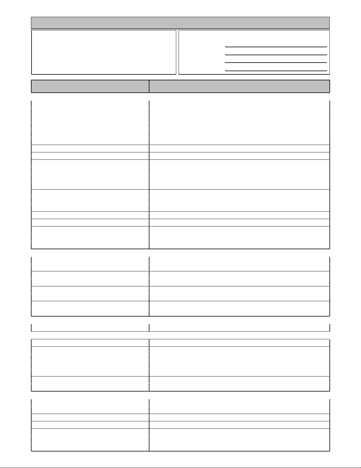
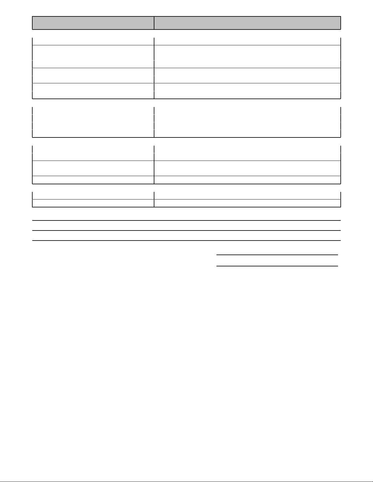
Accelerator pedal sensor
Function
The spindle which is connected to the accelerator pedal operates the position sensor. The sensor comprises a carbon strip
and a stylus, the spindle operates the stylus. The stylus moves over the carbon strip, the voltage on the stylus depends on
the position at which the stylus touches the carbon strip. Based on the output voltage the control unit determines fuel
delivery.
Info
Quickcheck
Check connector(s): Inspect the connector(s) and if necessary clean or fix them to make sure the con
supply voltage accelerator pedal position sensor: Turn off ignition. Remove connector from pedal position sensor. Turn
ignition on. Measure voltage between supply terminal and the negative terminal of the battery. It should equal specified
voltage. If not check wiring then check ECU. Check connection to ECU: Turn off ignition. Remove connector from pedal
position sensor and ECU. Measure the resistance between connectors terminal and the corresponding terminal in the ECU
connector. Should be < 1 ohm. If not check wiring. Check position sensor signal: Connect oscilloscope to the signal wire pin
of the ECU and ground. Turn ignition on and compare to the data
Page 4
e of the air increases.
nection is good. Check
direct ground or to the
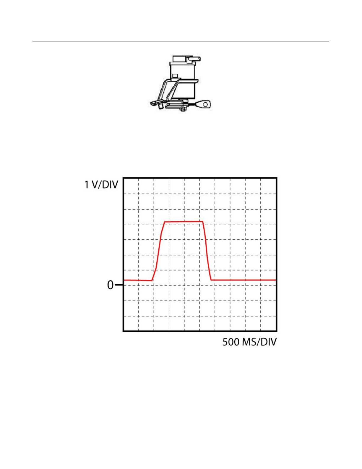
Air temperature sensor
Function
The air temperature sensor incorporates a NTC thermistor, the resistance decreases as the temperatur
As the temperature changes, the thermistor resistance changes, enabling the control unit to calculate the air temperature
from the level of voltage that is registered on the sensors' signal wire.
Quickcheck
Check connector(s): Inspect the connector(s) and if necessary clean or fix them to make sure the con
resistance: Turn off ignition. Remove connector from sensor. Measure resistance between pins of the sensor. Compare with
specified resistance. Check supply voltage: Turn off ignition. Remove connector from sensor. Turn ignition on and measure
successively voltage between connector terminal and the negative terminal of the battery. One should be 5 V. If not check
wiring then check ECU. Check connection to ECU: Turn off ignition. Remove connectors from sensor and ECU. Measure the
resistance between supply voltage connector terminal and the corresponding terminal in the ECU connector. It should be <
1 ohm. If not check wiring. Check ground: Check in schematic if ground connection is connected to a
ECU. When it is connected directly to ground: Turn off ignition. Remove connector from sensor and measure resistance
between ground connector terminal and the negative terminal of the battery. It should be < 1 ohm. If not check wiring.
When it is connected to the ECU: Turn off ignition. Remove connector from sensor and ECU. Measure resistance between
ground connector terminal and the corresponding terminal in the ECU connector. It should be < 1 ohm. If not check wiring
then check ECU.
Page 5
s passing through the
nection is good. Check
ery. Check the second
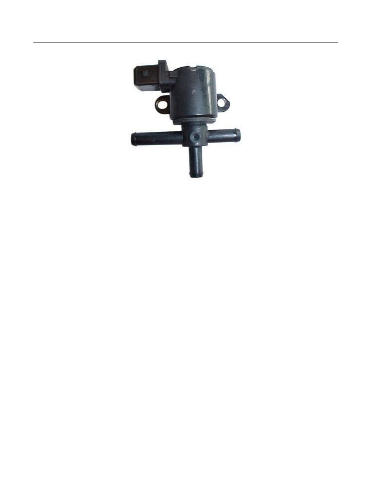
Boost pressure valve
Function
The solenoid controls a valve which opens or closes the air line between the waste gate valve and vacuum. When the valve
opens vacuum is applied to the waste gate valve, which in turn regulates the amount of exhaust gasse
exhaust gas turbine. In this way the turbo pressure is regulated.
Quickcheck
Check connector(s): Inspect the connector(s) and if necessary clean or fix them to make sure the con
resistance: Turn off ignition. Remove connector from solenoid. Locate the two pins of the solenoid. Measure resistance
between the two pins of the solenoid. Compare with specified resistance. Alternatively you can check functioning of the
solenoid by applying battery voltage to the two pins of the solenoid, the solenoid should "click". Check supply voltage: Turn
off ignition. Remove connector from solenoid. Locate the two connector terminals of the solenoid. Start the engine and
measure voltage between one connector terminal of the solenoid and the negative terminal of the batt
terminal of the solenoid, one of the two should equal the battery voltage. If not check wiring and if present fuse and relay.
Check connection to ECU: Turn off ignition. Remove connectors from solenoid and ECU. Locate the two connector terminals
of the solenoid. Measure the resistance between one of the two connector terminals of the solenoid and the corresponding
terminal in the ECU connector. Check the other terminal of the solenoid, one of the two should be < 1 ohm. If not check
wiring.
Page 6
ery. Both should equal
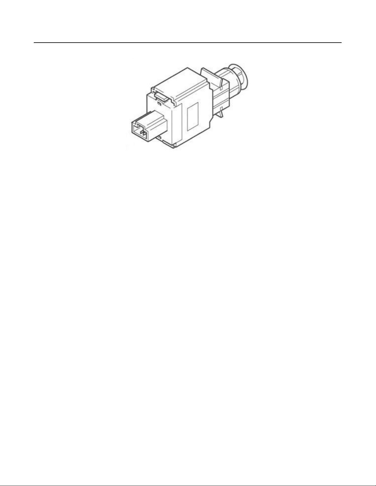
Brake pedal switch
Function
Engaging the brakes is detected by the brake pedal switch. There are single and double switches. Single switches send a
voltage signal to the control unit, thus signaling that the brakes are engaged. In a double switch the additional switch
actuates the brake lights.
Fault finding:
Check connector(s): Inspect the connector(s) and if necessary clean or fix them to make sure the connection is good.
Check supply voltage:
Turn off ignition. Remove connector from brake pedal switch.
Turn ignition on. Measure voltage between connector terminal + and the negative terminal of the batt
battery voltage. If not check wiring, relay and fuse(s).
Check connection to ECU:
Turn off ignition. Remove connector from brake pedal switch.
Measure the resistance between connector terminal + and - and the corresponding terminals in the ECU connector. Both
should be < 1 ohm. If not check wiring.
Check switch signal:
Connect oscilloscope or voltage meter to the pin of the ECU which corresponds to the brake pedal switch and ground. Turn
ignition on, output voltage should equal battery voltage. Press brake, output voltage should be 0 V. Connect oscilloscope or
voltage meter to the pin of the ECU which corresponds to the brake light switch and ground. Turn ignition on, output
voltage should be 0 V. Press brake, output voltage should equal battery voltage.
Page 7

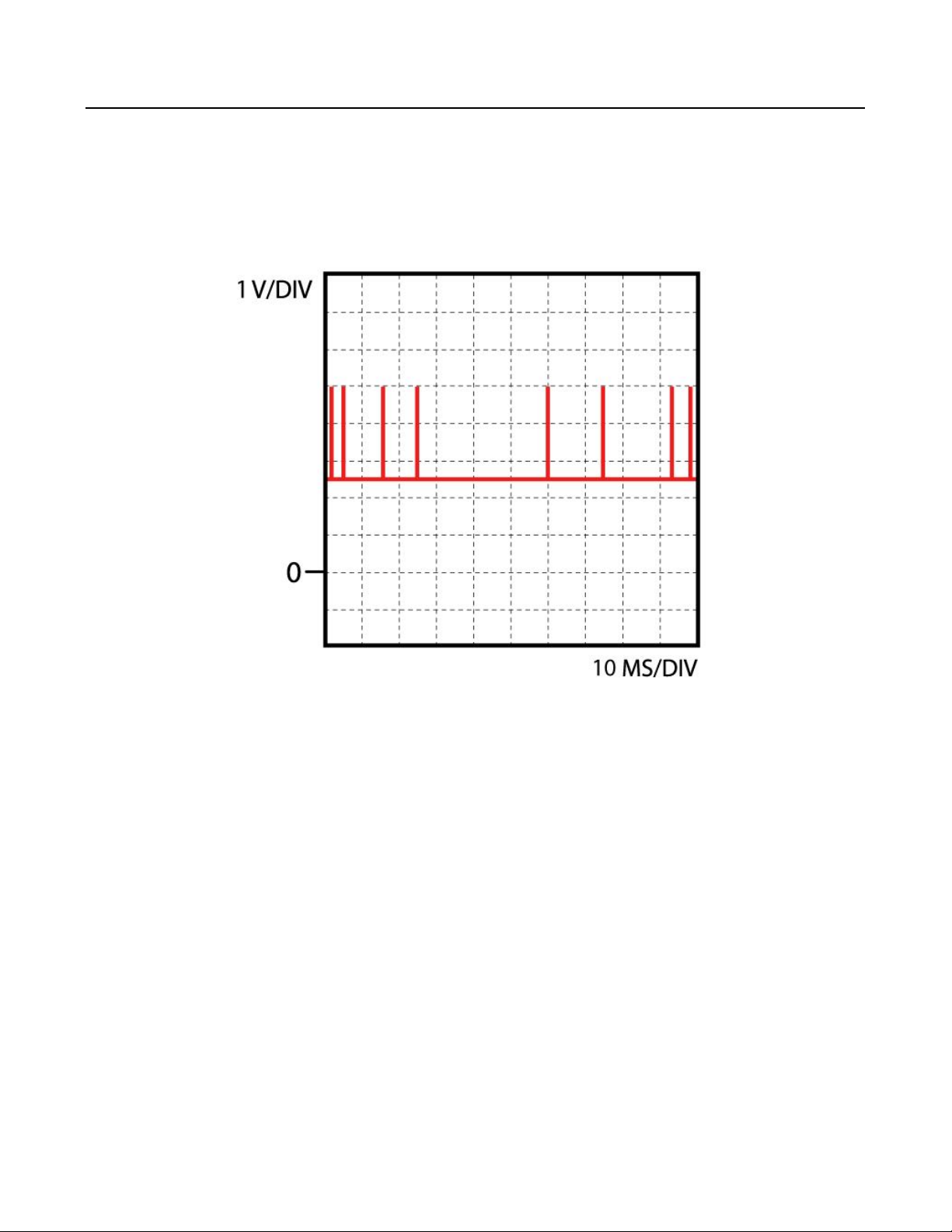
CAN BUS SAE J1708
Function
CAN bus connection SAE J1708 is a data chain used to send trouble code information etc. The voltage on the data chain
varies and depends on the number of ECUs and the traffic on the line.
Page 8
CAN BUS SAE J1939
Function
CAN bus connection SAE J1939 is an electric control chain used to send data that the system uses for control functions. The
voltage on the control chain varies and depends on the number of ECUs and the traffic on the line.
Info
Page 9
ECU lamp
Function
The control unit actuates the check engine light when it senses inadequate functioning of the motormanagement system.
Page 10
specified resistance.
resistance between
ng. When it is connected
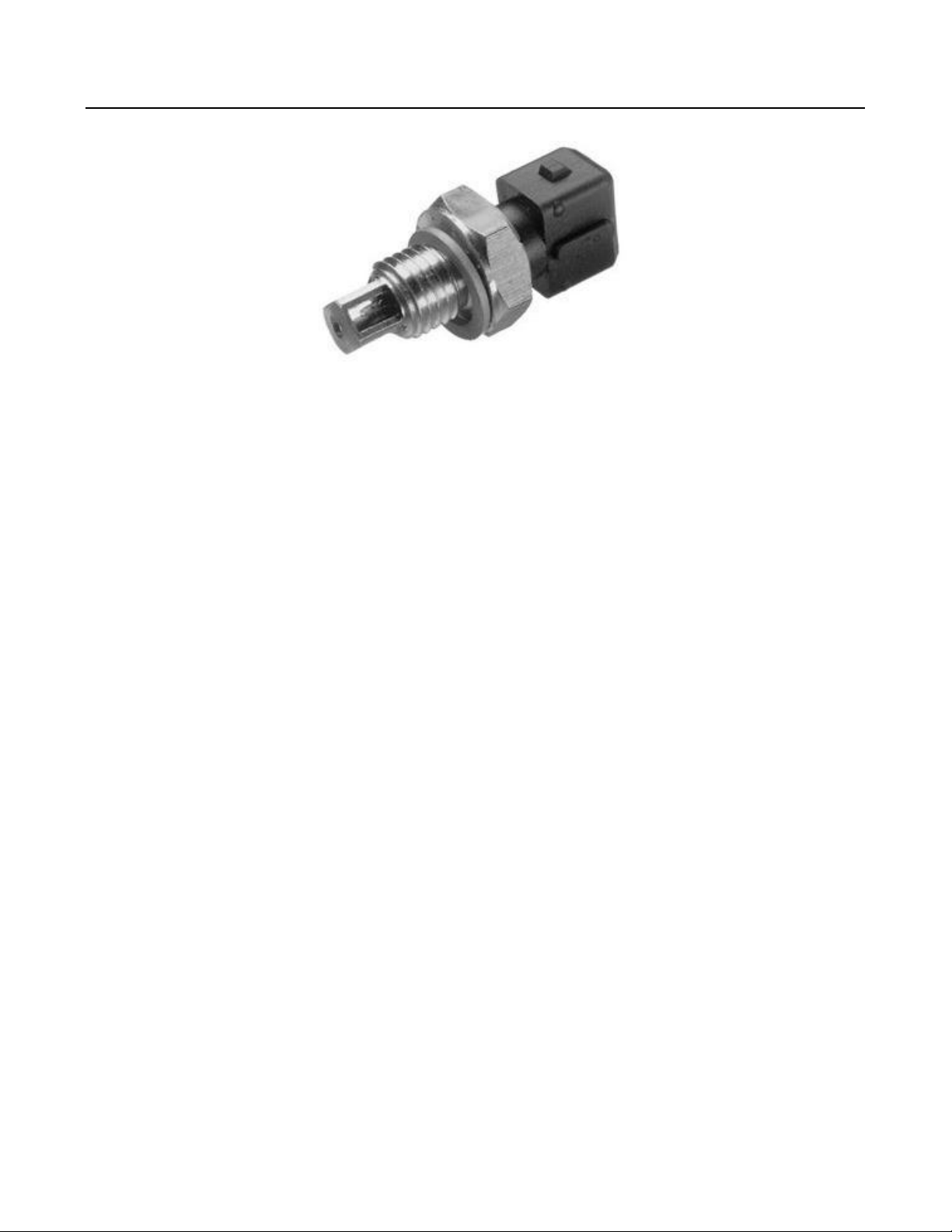
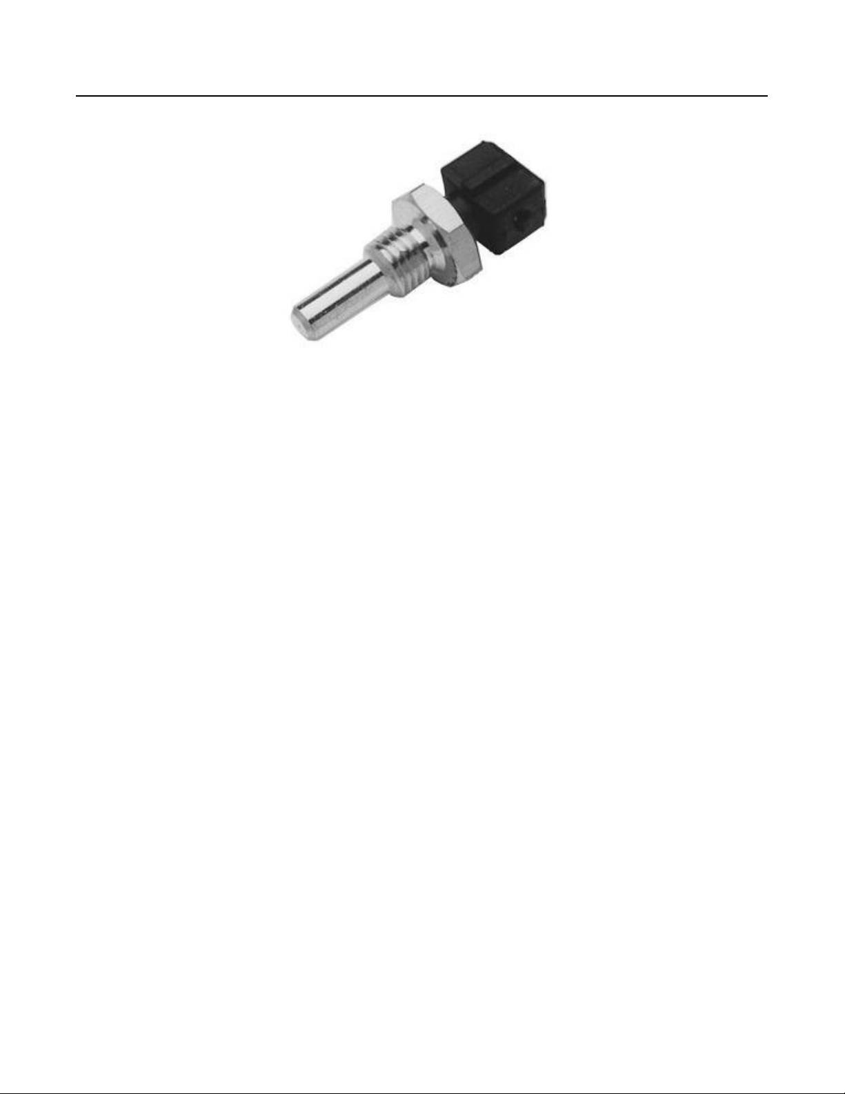
Coolant temperature sensor
Function
The coolant temperature sensor incorporates a NTC thermistor, the resistance decreases as the temperature of the coolant
increases. As the temperature changes, the thermistor resistance changes, enabling the control unit to calculate the coolant
temperature from the level of voltage that is registered on the sensors' signal wire.
Quickcheck
Inspect the connector(s) and if necessary clean or fix them to make sure the connection is good. Check resistance: Turn off
ignition. Remove connector from sensor. Measure resistance between pins of the sensor. Compare with
Check supply voltage: Turn off ignition. Remove connector from sensor. Turn ignition on and measure successively voltage
between connector terminal and the negative terminal of the battery. One should be 5 V. If not check wiring then check
ECU. Check connection to ECU: Turn off ignition. Remove connectors from sensor and ECU. Measure the
supply voltage connector terminal and the corresponding terminal in the ECU connector. It should be < 1 ohm. If not check
wiring. Check ground: Check in schematic if ground connection is connected to a direct ground or to the ECU. When it is
connected directly to ground: Turn off ignition. Remove connector from sensor and measure resistance between ground
connector terminal and the negative terminal of the battery. It should be < 1 ohm. If not check wiri
to the ECU: Turn off ignition. Remove connector from sensor and ECU. Measure resistance between ground connector
terminal and the corresponding terminal in the ECU connector. It should be < 1 ohm. If not check wiring then check ECU.
Page 11
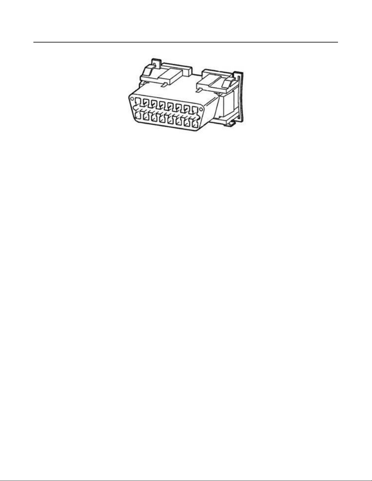
Diagnostic connector
Function
The diagnostic connector is connected to the control unit. It facilitates communication with the control unit to get
information on stored error codes and/or operating states of sensors and actuators.
Fault finding:
"Check connector(s): Inspect the connector(s) and if necessary clean or fix them to make sure the connection is good.
Check in schematic which diagnostic connector terminal is (are) connected to the connector terminal(s) of the ECU
connector or ground. Measure the resistance between the ECU connector terminal(s) and each pin of the diagnostic
connector. The resistance between the ECU connector terminal(s) and the corresponding terminal in the diagnostic
connector should be < 1 ohm.
Measure the resistance between the negative terminal of the battery and each pin of the diagnostic connector. The
resistance between the negative battery terminal and the corresponding terminal in the diagnostic connector should be < 1
ohm.
Page 12
nector terminal(s) and
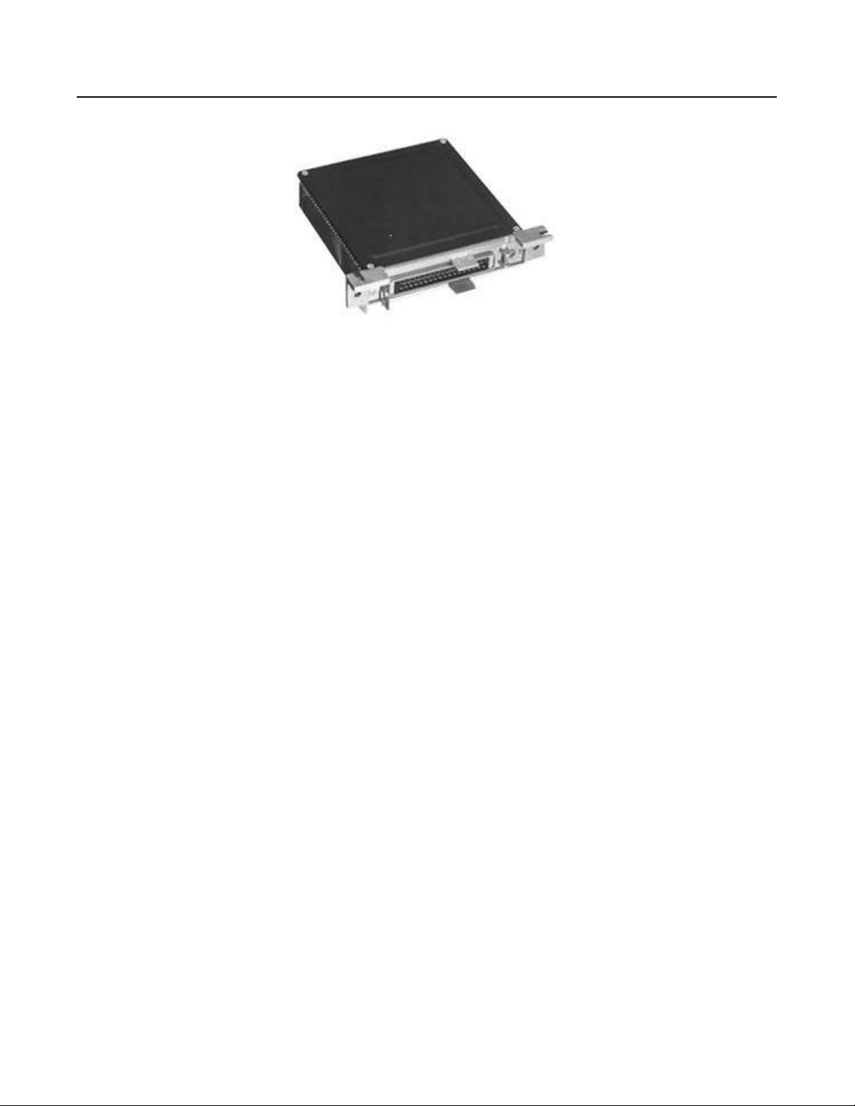
ECU
Function
The control unit is the electronic processing unit for the motormanagement system. The control unit has to ensure that the
engine receives the right amount of fuel, the right injection timing and a proper idle control in every operating state. The
control unit uses sensors to determine engine operating conditions. Depending on the engine conditions, the control unit
activates actuators.
Quickcheck
Check connector(s): Inspect the connector(s) and if necessary clean or fix them to make sure the connection is good. When
you suspect the control unit is faulty make sure all sensors, actuators and the communication with other control units
function properly. Furthermore check the supply voltage and ground connections of the control unit: Turn ignition off.
Remove ECU connector. Locate the supply voltage connections. Turn ignition on, measure voltage between corresponding
connector terminal(s) and the negative terminal of the battery, these should equal battery voltage. If not check wiring and
fuse. Turn ignition off. Locate the ground connections. Measure resistance between corresponding con
the negative terminal of the battery, these should be < 1 ohm.
Page 13
nection is good. Check
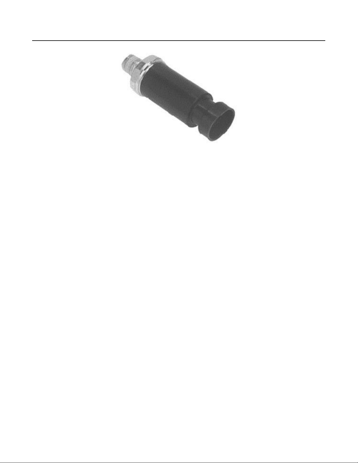
Exhaust pressure sensor
Function
The pressure in the exhaust is measured using the exhaust pressure sensor. The sensor is a transducer, the sensor senses
the absolute pressure in the exhaust and transduces this to a DC voltage signal.
Quickcheck
Check connector(s): Inspect the connector(s) and if necessary clean or fix them to make sure the con
supply voltage: Turn off ignition. Remove connector from sensor. Turn ignition on and measure voltage between the
supplyterminal and negative terminal of the battery. It should be 5 V. Check connection to ECU: Turn off ignition. Remove
connector from sensor and ECU. Measure the resistance between the terminals and the corresponding terminals in the ECU
connector. They all should be < 1 ohm. If not check wiring.
Page 14

nection is good. Check
iesel pump and ECU.
Fuel temperature sensor
Function
The fuel temperature sensor incorporates a NTC thermistor, the resistance decreases as the temperature of the fuel
increases. As the temperature changes, the thermistor resistance changes, enabling the control unit to calculate the fuel
temperature from the level of voltage that is registered on the sensors' signal wire.
Quickcheck
Check connector(s): Inspect the connector(s) and if necessary clean or fix them to make sure the con
resistance: Turn off ignition. Remove connector from diesel pump. Measure resistance between pin 1 and 2 of the
connector. Compare with specified resistance. Check supply voltage: Turn off ignition. Remove connector from diesel pump.
Turn ignition on and measure voltage between terminal 4 and the negative terminal of the battery. It should equal 5 V. If
not check wiring then check ECU. Check connection to ECU: Turn off ignition. Remove connector from d
Measure the resistance between terminal 1, 2 and the corresponding terminals in the ECU connector, each one should be <
1 ohm. If not check wiring.
Page 15

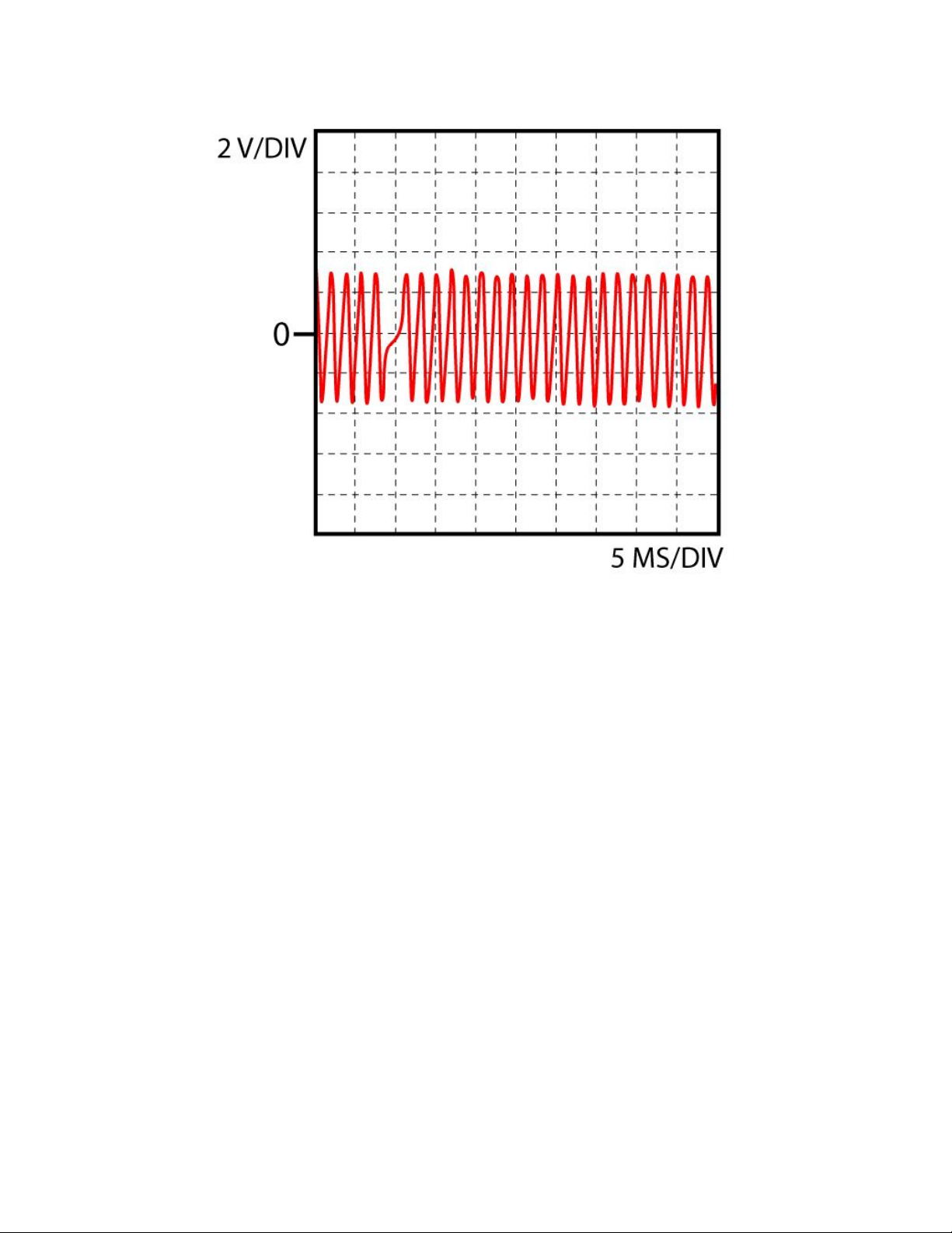
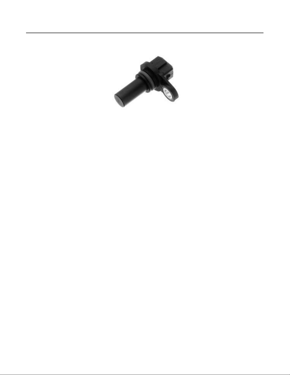
Inductive position sensor 1
Function
Function:
The sensor contains three parts: a coil, a magnet and a soft iron core. The teeth of a gearwheel move past the magnetic
pickup which changes the magnetic field of the magnet, increasing when a tooth approaches and decreasing when a tooth
moves away. These changes result in an AC voltage produced in the coil. Engine rpm and/or TDC are determined in this
way.
Trouble shooting:
"Check connector(s): Inspect the connector(s) and if necessary clean or fix them to make sure the connection is good.
Check resistance:
Turn off ignition. Remove connector from pickup sensor.
Measure resistance between the two pins of the coil of the pickup sensor. Compare with specified resistance.
Check connection to ECU:
Turn off ignition. Remove connector from pickup sensor and ECU.
Measure the resistance between each coil connector terminal and the corresponding terminals in the ECU connector. Both
should be < 1 ohm.
If present check shield connection:
Check in schematic if the shield terminal is connected to a direct ground or to the ECU. When it is connected to a direct
ground: Turn off ignition. Remove connector from pickup sensor. Measure resistance between the shield connector terminal
and the negative terminal of the battery. It should be < 1 ohm. When it is connected to the ECU: Turn off ignition. Remove
connector from pickup sensor and ECU. Measure the resistance between the shield connector terminal and the
corresponding terminal in the ECU connector. It should be < 1 ohm. If not check wiring.
Check sensor signal:
Connect oscilloscope to signal wire pin of the ECU and ground. Start or crank the engine and compare to the scope image
shown."
Info
Page 16
Page 17
Inductive position sensor 2
Function
Function:
The sensor contains three parts: a coil, a magnet and a soft iron core. The teeth of a gearwheel move past the magnetic
pickup which changes the magnetic field of the magnet, increasing when a tooth approaches and decreasing when a tooth
moves away. These changes result in an AC voltage produced in the coil. Engine rpm and/or TDC are determined in this
way.
Trouble shooting:
"Check connector(s): Inspect the connector(s) and if necessary clean or fix them to make sure the connection is good.
Check resistance:
Turn off ignition. Remove connector from pickup sensor.
Measure resistance between the two pins of the coil of the pickup sensor. Compare with specified resistance.
Check connection to ECU:
Turn off ignition. Remove connector from pickup sensor and ECU.
Measure the resistance between each coil connector terminal and the corresponding terminals in the ECU connector. Both
should be < 1 ohm.
If present check shield connection:
Check in schematic if the shield terminal is connected to a direct ground or to the ECU. When it is connected to a direct
ground: Turn off ignition. Remove connector from pickup sensor. Measure resistance between the shield connector terminal
and the negative terminal of the battery. It should be < 1 ohm. When it is connected to the ECU: Turn off ignition. Remove
connector from pickup sensor and ECU. Measure the resistance between the shield connector terminal and the
corresponding terminal in the ECU connector. It should be < 1 ohm. If not check wiring.
Check sensor signal:
Connect oscilloscope to signal wire pin of the ECU and ground. Start or crank the engine and compare to the scope image
shown."
Info
Page 18

Page 19

Inductive position sensor
Function
Function:
The sensor contains three parts: a coil, a magnet and a soft iron core. The teeth of a gearwheel move past the magnetic
pickup which changes the magnetic field of the magnet, increasing when a tooth approaches and decreasing when a tooth
moves away. These changes result in an AC voltage produced in the coil. Engine rpm and/or TDC are determined in this
way.
Trouble shooting:
"Check connector(s): Inspect the connector(s) and if necessary clean or fix them to make sure the connection is good.
Check resistance:
Turn off ignition. Remove connector from pickup sensor.
Measure resistance between the two pins of the coil of the pickup sensor. Compare with specified resistance.
Check connection to ECU:
Turn off ignition. Remove connector from pickup sensor and ECU.
Measure the resistance between each coil connector terminal and the corresponding terminals in the ECU connector. Both
should be < 1 ohm.
If present check shield connection:
Check in schematic if the shield terminal is connected to a direct ground or to the ECU. When it is connected to a direct
ground: Turn off ignition. Remove connector from pickup sensor. Measure resistance between the shield connector terminal
and the negative terminal of the battery. It should be < 1 ohm. When it is connected to the ECU: Turn off ignition. Remove
connector from pickup sensor and ECU. Measure the resistance between the shield connector terminal and the
corresponding terminal in the ECU connector. It should be < 1 ohm. If not check wiring.
Check sensor signal:
Connect oscilloscope to signal wire pin of the ECU and ground. Start or crank the engine and compare to the scope image
shown."
Info
Page 20

Page 21

nection is good. Check
terminal in the ECU
wo connector terminals
Unit Injector 1
Function
The unit injector is a one-cylinder injection pump and injection valve built into one unit.
The unit injector is activated mechanically by the camshaft that is used to produce the high injection pressure of up to
approx. 2000 bar. The actual injection takes place via the solenoid valve inside the injector that pulls up a fitting connected
with the injector needle. Thus, fuel is injected directly into the combustion chamber of the cylinder. The injector valve is
activated by the control unit where it receives a signal about injection amount and injection point.
One unit injector is used for every cylinder.
Info
Quickcheck
Check connector(s): Inspect the connector(s) and if necessary clean or fix them to make sure the con
resistance: Turn off ignition. Remove connector(s) from injector(s). Measure resistance between the two pins of the
injector. Compare with specified resistance. Check connection to ECU: Turn off ignition. Remove connector(s) from injector
(s) and ECU. Measure the resistance between one of the two connector terminals and the corresponding
connector. Check the other terminal, one of the two should be < 1 ohm. If not check wiring. Check connection to ground:
Turn off ignition. Remove connector(s) from injector(s). Measure the resistance between one of the t
and the negative battery pole. Check the other terminal, one of the two should be < 1 ohm. If not check wiring. Check
injector activation: Connect oscilloscope to one of the signal wire pins of the ECU and ground. Start or crank the engine and
compare to the scope image shown.
Page 22

nection is good. Check
terminal in the ECU
wo connector terminals
Unit Injector 1
Function
The unit injector is a one-cylinder injection pump and injection valve built into one unit.
The unit injector is activated mechanically by the camshaft that is used to produce the high injection pressure of up to
approx. 2000 bar. The actual injection takes place via the solenoid valve inside the injector that pulls up a fitting connected
with the injector needle. Thus, fuel is injected directly into the combustion chamber of the cylinder. The injector valve is
activated by the control unit where it receives a signal about injection amount and injection point.
One unit injector is used for every cylinder.
Info
Quickcheck
Check connector(s): Inspect the connector(s) and if necessary clean or fix them to make sure the con
resistance: Turn off ignition. Remove connector(s) from injector(s). Measure resistance between the two pins of the
injector. Compare with specified resistance. Check connection to ECU: Turn off ignition. Remove connector(s) from injector
(s) and ECU. Measure the resistance between one of the two connector terminals and the corresponding
connector. Check the other terminal, one of the two should be < 1 ohm. If not check wiring. Check connection to ground:
Turn off ignition. Remove connector(s) from injector(s). Measure the resistance between one of the t
and the negative battery pole. Check the other terminal, one of the two should be < 1 ohm. If not check wiring. Check
injector activation: Connect oscilloscope to one of the signal wire pins of the ECU and ground. Start or crank the engine and
compare to the scope image shown.
Page 23

nection is good. Check
terminal in the ECU
wo connector terminals
Unit Injector 2
Function
The unit injector is a one-cylinder injection pump and injection valve built into one unit.
The unit injector is activated mechanically by the camshaft that is used to produce the high injection pressure of up to
approx. 2000 bar. The actual injection takes place via the solenoid valve inside the injector that pulls up a fitting connected
with the injector needle. Thus, fuel is injected directly into the combustion chamber of the cylinder. The injector valve is
activated by the control unit where it receives a signal about injection amount and injection point.
One unit injector is used for every cylinder.
Info
Quickcheck
Check connector(s): Inspect the connector(s) and if necessary clean or fix them to make sure the con
resistance: Turn off ignition. Remove connector(s) from injector(s). Measure resistance between the two pins of the
injector. Compare with specified resistance. Check connection to ECU: Turn off ignition. Remove connector(s) from injector
(s) and ECU. Measure the resistance between one of the two connector terminals and the corresponding
connector. Check the other terminal, one of the two should be < 1 ohm. If not check wiring. Check connection to ground:
Turn off ignition. Remove connector(s) from injector(s). Measure the resistance between one of the t
and the negative battery pole. Check the other terminal, one of the two should be < 1 ohm. If not check wiring. Check
injector activation: Connect oscilloscope to one of the signal wire pins of the ECU and ground. Start or crank the engine and
compare to the scope image shown.
Page 24

nection is good. Check
terminal in the ECU
wo connector terminals
Unit Injector 3
Function
The unit injector is a one-cylinder injection pump and injection valve built into one unit.
The unit injector is activated mechanically by the camshaft that is used to produce the high injection pressure of up to
approx. 2000 bar. The actual injection takes place via the solenoid valve inside the injector that pulls up a fitting connected
with the injector needle. Thus, fuel is injected directly into the combustion chamber of the cylinder. The injector valve is
activated by the control unit where it receives a signal about injection amount and injection point.
One unit injector is used for every cylinder.
Info
Quickcheck
Check connector(s): Inspect the connector(s) and if necessary clean or fix them to make sure the con
resistance: Turn off ignition. Remove connector(s) from injector(s). Measure resistance between the two pins of the
injector. Compare with specified resistance. Check connection to ECU: Turn off ignition. Remove connector(s) from injector
(s) and ECU. Measure the resistance between one of the two connector terminals and the corresponding
connector. Check the other terminal, one of the two should be < 1 ohm. If not check wiring. Check connection to ground:
Turn off ignition. Remove connector(s) from injector(s). Measure the resistance between one of the t
and the negative battery pole. Check the other terminal, one of the two should be < 1 ohm. If not check wiring. Check
injector activation: Connect oscilloscope to one of the signal wire pins of the ECU and ground. Start or crank the engine and
compare to the scope image shown.
Page 25

nection is good. Check
terminal in the ECU
wo connector terminals
Unit Injector 4
Function
The unit injector is a one-cylinder injection pump and injection valve built into one unit.
The unit injector is activated mechanically by the camshaft that is used to produce the high injection pressure of up to
approx. 2000 bar. The actual injection takes place via the solenoid valve inside the injector that pulls up a fitting connected
with the injector needle. Thus, fuel is injected directly into the combustion chamber of the cylinder. The injector valve is
activated by the control unit where it receives a signal about injection amount and injection point.
One unit injector is used for every cylinder.
Info
Quickcheck
Check connector(s): Inspect the connector(s) and if necessary clean or fix them to make sure the con
resistance: Turn off ignition. Remove connector(s) from injector(s). Measure resistance between the two pins of the
injector. Compare with specified resistance. Check connection to ECU: Turn off ignition. Remove connector(s) from injector
(s) and ECU. Measure the resistance between one of the two connector terminals and the corresponding
connector. Check the other terminal, one of the two should be < 1 ohm. If not check wiring. Check connection to ground:
Turn off ignition. Remove connector(s) from injector(s). Measure the resistance between one of the t
and the negative battery pole. Check the other terminal, one of the two should be < 1 ohm. If not check wiring. Check
injector activation: Connect oscilloscope to one of the signal wire pins of the ECU and ground. Start or crank the engine and
compare to the scope image shown.
Page 26

nection is good. Check
terminal in the ECU
wo connector terminals
Unit Injector 5
Function
The unit injector is a one-cylinder injection pump and injection valve built into one unit.
The unit injector is activated mechanically by the camshaft that is used to produce the high injection pressure of up to
approx. 2000 bar. The actual injection takes place via the solenoid valve inside the injector that pulls up a fitting connected
with the injector needle. Thus, fuel is injected directly into the combustion chamber of the cylinder. The injector valve is
activated by the control unit where it receives a signal about injection amount and injection point.
One unit injector is used for every cylinder.
Info
Quickcheck
Check connector(s): Inspect the connector(s) and if necessary clean or fix them to make sure the con
resistance: Turn off ignition. Remove connector(s) from injector(s). Measure resistance between the two pins of the
injector. Compare with specified resistance. Check connection to ECU: Turn off ignition. Remove connector(s) from injector
(s) and ECU. Measure the resistance between one of the two connector terminals and the corresponding
connector. Check the other terminal, one of the two should be < 1 ohm. If not check wiring. Check connection to ground:
Turn off ignition. Remove connector(s) from injector(s). Measure the resistance between one of the t
and the negative battery pole. Check the other terminal, one of the two should be < 1 ohm. If not check wiring. Check
injector activation: Connect oscilloscope to one of the signal wire pins of the ECU and ground. Start or crank the engine and
compare to the scope image shown.
Page 27

nection is good. Check
terminal in the ECU
wo connector terminals
Unit Injector 6
Function
The unit injector is a one-cylinder injection pump and injection valve built into one unit.
The unit injector is activated mechanically by the camshaft that is used to produce the high injection pressure of up to
approx. 2000 bar. The actual injection takes place via the solenoid valve inside the injector that pulls up a fitting connected
with the injector needle. Thus, fuel is injected directly into the combustion chamber of the cylinder. The injector valve is
activated by the control unit where it receives a signal about injection amount and injection point.
One unit injector is used for every cylinder.
Info
Quickcheck
Check connector(s): Inspect the connector(s) and if necessary clean or fix them to make sure the con
resistance: Turn off ignition. Remove connector(s) from injector(s). Measure resistance between the two pins of the
injector. Compare with specified resistance. Check connection to ECU: Turn off ignition. Remove connector(s) from injector
(s) and ECU. Measure the resistance between one of the two connector terminals and the corresponding
connector. Check the other terminal, one of the two should be < 1 ohm. If not check wiring. Check connection to ground:
Turn off ignition. Remove connector(s) from injector(s). Measure the resistance between one of the t
and the negative battery pole. Check the other terminal, one of the two should be < 1 ohm. If not check wiring. Check
injector activation: Connect oscilloscope to one of the signal wire pins of the ECU and ground. Start or crank the engine and
compare to the scope image shown.
Page 28

r. The MAP sensor is a
to a DC voltage signal.
nection is good. Check
MAP-sensor
Function
The air pressure in the intake manifold is measured using the Manifold Absolute Pressure (MAP) senso
transducer, the MAP sensor senses the absolute presssure in the intake manifold and transduces this
Info
Quickcheck
Check connector(s): Inspect the connector(s) and if necessary clean or fix them to make sure the con
supply voltage: Turn off ignition. Remove connector from sensor. Turn ignition on and measure voltage between the suply
terminal and negative terminal of the battery. It should be 5 V. Check connection to ECU: Turn off ignition. Remove
connector from MAP sensor and ECU. Measure the resistance between MAP sensor terminals and the corresponding
terminals in the ECU connector. They all should be < 1 ohm. If not check wiring. Check MAP sensor signal: Connect
oscilloscope or voltmeter to the corresponding pin of the ECU (signal wire) and ground. Remove vacuum tube and connect
vacuum pump. Turn ignition on and apply several different pressures. Compare to the characteristic shown.
Page 29

Clutch switch
Function
Engaging the clutch pedal is detected by this switch. The control unit senses the voltage signal of this switch detecting that
the clutch is engaged.
Page 30

Speedometer
Function
Gives information about the speed of the car.
Page 31

1007
1012
1047
Page 32

1050
1079
1087
Page 33

1088
Page 34

Model
Yours sincerely
Year
Engine
Maintenance
Engine compartment OK Remarks
1 Check/ Change dust/ pollen filter
2 Clean radiator fly screen
Stralis 440 E 44 Cursor 13
2002-2009
F3B E0681C
Every spring
Iveco LV
Date:
Owner
Registration No.
Mileage
1. Reg. Date
06-07-2011Make
We have noted the following points, of which you should be aware, while
examining your vehicle:
n
n
n n
Date Mechanic
Page 35

Iveco LV Stralis 440 E 44 Cursor 13
Main bearings, Nm
Tightening of lower block. Step 1 outer position bolts 30 Nm. Step 2 inner position bolts 120 Nm.
Step 3 inner position bolts + 60°. Step 4 inner position bolts + 55°. Step 5 outer position bolts +
60°.
Page 36

Iveco LV Stralis 440 E 44 Cursor 13
Terminal definitions DIN 72 552
DIN 72 552
Klemmebetegnelser:
Terminal Definition:
-circuit terminal (magneto ignition)
-parallel battery switch)
- battery terminal or ground, direct
-parallel battery)
- terminal of battery II
- terminal of battery I
-33)
-33)
-parking switch-off
-speed range
-speed range
-speed range
Page 37

-starter parallel
-starter parallel
-repeating relay for
-signal circuit
-signal circuit
-parallel battery switch)
-locking relay
-locking relay
-repeating relay
-repeating relay
-parking switch-off
-washer pump
Page 38

High beam, high-beam indicator lamp
-flasher contact
-marker lamp: motorcycles, mopeds.
-marker lamps, tail lamps, license-plate lamps and
-panel lamps
-lamp changeover for single-axle tractors
-and-receptacle assembly for single-
-lamp cable with fuse in trailer
-intensity instrument-panel lamp, tail-lamp and
-marker lamp
-marker lamp, left
-marker lamp, right; license-plate lamp
-lamp armature, output
-lamp armature, output
-indicator lamp
-SEQUENCE CONTROL DEVICE
-valve control
-contact and changeover switches)
-contact switches)
Page 39

-position switches)-
-hand position
-hand position
-
-
B-
D-
-
-signal flasher)
Page 40

-signal switch
-signal lamps, left
-signal lamps, right
Cross-reference for old and new terminal designations in accordance with DIN 72 552.
Only terminal designations whose significance has altered are given.
-signal flasher)
30h I 45a
30h II 45b
31B- -
50 II 50c
51 -
D- -
Page 41

-signal flasher)
-
Page 42

Iveco LV Stralis 440 E 44 Cursor 13
Cylinder head bolts, stage 1, Nm
Tightening sequence
Pic. 1
Page 43

in the clutch casing (see arrow A)). Fit the measuring gauge to the roller bearing on the rocker arm
Iveco LV Stralis 440 E 44 Cursor 13
Timing gear:
Timing gear marking
Cylinder 1 in compression top. (Hole "11" in the flywheel, outside of the crank position sensor hole
of the flue injection nozzle on cylinder 1 (see arrow B), and prestress the measuring gauge (see
below). Turn the engine in the direction of revolution until the measuring gauge shows the
minimum deflection. Reset the measuring gauge and turn the engine in the direction of rotation
until the measuring gauge shows:
Engine type:
Height measured on the roller bearing Prestressing of measuring gauge
F2B (Euro 2) 2.43 ± 0.05 mm Prestressing 4 mm
F2B (Euro 3) 4.90 ± 0.05 mm Prestressing 6 mm
± 0.05 mm Prestressing 6 mm
± 0.05 mm Prestressing 6 mm
Check that the special tool (99360612) can be placed into the flywheel "11." hole without
resistance (see arrow A). If not, the securing bolt of the cam gear is not loose (see arrow C) and
the engine is turned approx. half a crank revolution back. Turn the engine forwards to the top and
fit the special tool (99360612) into the flywheel "11." hole (see arrow A). Tighten the cam gear
again and check using the measuring gauge again as previously described. Turn the crank to 54°
to before the top of cylinder 1 and place the special tool (99360612) into the flywheel hole (Note:
there should be two notches outside of the hole (see arrow D)). Check that the special tool
(99360613) can go over the marked tooth on the cam gear (see arrow E).
Page 44

Pic. 1
Page 45

Iveco LV Stralis 440 E 44 Cursor 13
Tightening torques
Tightening, NM
Page 46

Pic. 1
Page 47

Iveco LV Stralis 440 E 44 Cursor 13
Valve clearance, exhaust (cold/ hot)
Valve adjustment
Valve adjustment:
Measure by rocker arm / valve arm.
When valves overlap on: adjust on:
Page 48

Iveco LV Stralis 440 E 44 Cursor 13
Valve clearance, inlet (cold/ hot)
Valve adjustment
Valve adjustment:
Measure by rocker arm / valve arm.
When valves overlap on: adjust on:
Page 49

Iveco LV Stralis 440 E 44 Cursor 13
Manual transmission, litre
Gearbox no.: ZF 16S 181 / 221 = 13.0. ZF 16S 181 / 221 with retarder = 21.5. Eurotronic 12 AS
2301 / with retarder = 12.0 / 21.0. Eurotronic 12 AS 2601 / with retarder = 12.0 / 23.0.
Page 50

Troubleshooting-data
Stralis 440 E 44 Cursor 13
Model:
Motor:
F3B E0681C / Bosch MS6.2 Unit Injector
B11B11088
A31
A18
B20
B1
A2
A14
1007
A12
A23
Component: From: To: Condition: Value Measured:Pic.
. .. Connector seen from wire side
. .. Measurements taken with
connector installed
B1 Batt. -Battery (earth) Ignition on
B2 Batt. -Battery (earth) Ignition on
B11 B12CAN BUS SAE J1939 Ignition off
B12 B1 1087CAN BUS SAE J1939 Idle
CAN BUS SAE J1939 Idle
B35 B1Accelerator pedal sensor Ignition on
B16 B35Accelerator pedal sensor Ignition on
B23 B35Accelerator pedal sensor Ignition on, accelerator
released
B23 B35Accelerator pedal sensor Ignition on, accelerator fully
depressed
Boost pressure valve Ignition on
B26 B1Brake pedal switch Ignition on, brake pedal
released
B31 B1Brake pedal switch Ignition on, brake pedal
released
B31 B1Brake pedal switch Ignition on, brake pedal
depressed
B26 B1Brake pedal switch Ignition on, brake pedal
depressed
Clutch switch Ignition on
B20 B1Clutch switch Ignition on, pedal activated
B15 B1Ignition Ignition on
B15 B1Ignition Ignition off
A7 A16 1050Inductive position sensor Idle
Inductive position sensor 1 Starter rpm
A1 A14 1012Inductive position sensor 2 Starter rpm
A17 A23MAP-sensor Ignition on
A12 A23MAP-sensor Ignition on
A23 B1MAP-sensor Ignition on
MAP-sensor 2000 rpm
A12 A23MAP-sensor Ignition on, at 2500 - 3000
mbar
B27 B1Relay Ignition on
B3 B1Relay Ignition on
B4 B1Relay Ignition on
B4 B1Relay Ignition off
B27 B1Relay Ignition off
.
.
0 V
0 V
55 - 65 ohm
0 V
4,5 - 5,5 V
0,2 - 0,6 V
3,5 - 4 V
22 - 28 V
22 - 28 V
0 V
22 - 28 V
0 V
22 - 28 V
0 V
22 - 28 V
0 V
4,5 - 5,5 V
0,9 - 1,1 V
0 V
1,3 - 1,7 V
3,4 - 4,7 V
0 - 1 V
22 - 28 V
22 - 28 V
0 V
22 - 28 V
Page 51

Troubleshooting-data
Stralis 440 E 44 Cursor 13
Model:
Motor:
F3B E0681C / Bosch MS6.2 Unit Injector
B3
B1
A26
A25
1079
Component: From: To: Condition: Value Measured:Pic.
Relay Ignition off
B29 B1 1047Speedometer Vehicle in motion
A35 A24 1079Unit Injector 1 Idle
A34 A24 1079Unit Injector 2 Idle
A33 A24 1079Unit Injector 3 Idle
Unit Injector 4 Idle
A28 A25 1079Unit Injector 5 Idle
A27 A25 1079Unit Injector 6 Idle
0 V
Page 52

Troubleshooting-data
Stralis 440 E 44 Cursor 13
Model:
Motor:
F3B E0681C / Bosch MS6.2 Unit Injector
B11B11088
A31
A18
B20
B1
A2
A14
1007
A12
A23
Component: From: To: Condition: Value Measured:Pic.
. .. Connector seen from wire side
. .. Measurements taken with
connector installed
B1 Batt. -Battery (earth) Ignition on
B2 Batt. -Battery (earth) Ignition on
B11 B12CAN BUS SAE J1939 Ignition off
B12 B1 1087CAN BUS SAE J1939 Idle
CAN BUS SAE J1939 Idle
B35 B1Accelerator pedal sensor Ignition on
B16 B35Accelerator pedal sensor Ignition on
B23 B35Accelerator pedal sensor Ignition on, accelerator
released
B23 B35Accelerator pedal sensor Ignition on, accelerator fully
depressed
Boost pressure valve Ignition on
B26 B1Brake pedal switch Ignition on, brake pedal
released
B31 B1Brake pedal switch Ignition on, brake pedal
released
B31 B1Brake pedal switch Ignition on, brake pedal
depressed
B26 B1Brake pedal switch Ignition on, brake pedal
depressed
Clutch switch Ignition on
B20 B1Clutch switch Ignition on, pedal activated
B15 B1Ignition Ignition on
B15 B1Ignition Ignition off
A7 A16 1050Inductive position sensor Idle
Inductive position sensor 1 Starter rpm
A1 A14 1012Inductive position sensor 2 Starter rpm
A17 A23MAP-sensor Ignition on
A12 A23MAP-sensor Ignition on
A23 B1MAP-sensor Ignition on
MAP-sensor 2000 rpm
A12 A23MAP-sensor Ignition on, at 2500 - 3000
mbar
B27 B1Relay Ignition on
B3 B1Relay Ignition on
B4 B1Relay Ignition on
B4 B1Relay Ignition off
B27 B1Relay Ignition off
.
.
0 V
0 V
55 - 65 ohm
0 V
4,5 - 5,5 V
0,2 - 0,6 V
3,5 - 4 V
22 - 28 V
22 - 28 V
0 V
22 - 28 V
0 V
22 - 28 V
0 V
22 - 28 V
0 V
4,5 - 5,5 V
0,9 - 1,1 V
0 V
1,3 - 1,7 V
3,4 - 4,7 V
0 - 1 V
22 - 28 V
22 - 28 V
0 V
22 - 28 V
Page 53

Troubleshooting-data
Stralis 440 E 44 Cursor 13
Model:
Motor:
F3B E0681C / Bosch MS6.2 Unit Injector
B3
B1
A26
A25
1079
Component: From: To: Condition: Value Measured:Pic.
Relay Ignition off
B29 B1 1047Speedometer Vehicle in motion
A35 A24 1079Unit Injector 1 Idle
A34 A24 1079Unit Injector 2 Idle
A33 A24 1079Unit Injector 3 Idle
Unit Injector 4 Idle
A28 A25 1079Unit Injector 5 Idle
A27 A25 1079Unit Injector 6 Idle
0 V
Page 54

A19
Speedometer
A95
ECU
B156
Inductive position sensor 1
B157
Inductive position sensor 2
B163
Inductive position sensor
B164
Solinoid valve exh. Brake 1
B22
Coolant temperature sensor
B23
Air temperature sensor
B27
Exhaust pressure sensor
B36
Fuel temperature sensor
B39
Accelerator pedal sensor
B79
MAP-sensor
F-
Fuse
G15
CAN BUS SAE J1708
G16
CAN BUS SAE J1939
H11
ECU lamp
K96
Relay
R11
Resistor
S14
Brake pedal switch
S15
Clutch switch
X11
Diagnostic connector
Y42
Boost pressure valve
Y66
Unit Injector 1
Y67
Unit Injector 2
Y68
Unit Injector 3
Y69
Unit Injector 4
Y95
Unit Injector 5
Y96
Unit Injector 6
Page 55

Page 56

Page 57

Fault-codes
Stralis 440 E 44 Cursor 13
Model:
Motor:
F3B E0681C / ABS-ASR Basis 4 Channel
Faultcode Possible cause(s)
CAN communication, Air gap, Wrong,01 - 01, Wheel speed sensor 1L
CAN communication, Tyre size, Wrong,01 - 02, Wheel speed sensor 1L
Short circuit to plus,01 - 03, Wheel speed sensor 1L
Short circuit to ground,01 - 04, Wheel speed sensor 1L
Circuit open,01 - 05, Wheel speed sensor 1L
Short circuit,01 - 06, Wheel speed sensor 1L
CAN communication, Toothed ring, Wrong,01 - 07, Wheel speed sensor 1L
Wheel slip detected,01 - 08, Wheel speed sensor 1L
Fault in circuit,01 - 09, Wheel speed sensor 1L
Speed low,01 - 0A, Wheel speed sensor 1L
Signal error/ signal variation,01 - 0B, Wheel speed sensor 1L
Signal, Input too high,01 - 0C, Wheel speed sensor 1L
CAN communication, Air gap, Wrong,02 - 01, Wheel speed sensor 1R
CAN communication, Tyre size, Wrong,02 - 02, Wheel speed sensor 1R
Short circuit to plus,02 - 03, Wheel speed sensor 1R
Short circuit to ground,02 - 04, Wheel speed sensor 1R
Circuit open,02 - 05, Wheel speed sensor 1R
Short circuit,02 - 06, Wheel speed sensor 1R
CAN communication, Toothed ring, Wrong,02 - 07, Wheel speed sensor 1R
Wheel slip detected,02 - 08, Wheel speed sensor 1R
Fault in circuit,02 - 09, Wheel speed sensor 1R
Speed low,02 - 0A, Wheel speed sensor 1R
Signal error/ signal variation,02 - 0B, Wheel speed sensor 1R
Signal, Input too high,02 - 0C, Wheel speed sensor 1R
CAN communication, Air gap, Wrong,03 - 01, Wheel speed sensor 2L
CAN communication, Tyre size, Wrong,03 - 02, Wheel speed sensor 2L
Short circuit to plus,03 - 03, Wheel speed sensor 2L
Short circuit to ground,03 - 04, Wheel speed sensor 2L
Circuit open,03 - 05, Wheel speed sensor 2L
Short circuit,03 - 06, Wheel speed sensor 2L
CAN communication, Toothed ring, Wrong,03 - 07, Wheel speed sensor 2L
Wheel slip detected,03 - 08, Wheel speed sensor 2L
Fault in circuit,03 - 09, Wheel speed sensor 2L
Speed low,03 - 0A, Wheel speed sensor 2L
Signal error/ signal variation,03 - 0B, Wheel speed sensor 2L
Signal, Input too high,03 - 0C, Wheel speed sensor 2L
CAN communication, Air gap, Wrong,04 - 01, Wheel speed sensor 2R
CAN communication, Tyre size, Wrong,04 - 02, Wheel speed sensor 2R
Short circuit to plus,04 - 03, Wheel speed sensor 2R
Short circuit to ground,04 - 04, Wheel speed sensor 2R
Circuit open,04 - 05, Wheel speed sensor 2R
Short circuit,04 - 06, Wheel speed sensor 2R
CAN communication, Toothed ring, Wrong,04 - 07, Wheel speed sensor 2R
Wheel slip detected,04 - 08, Wheel speed sensor 2R
Fault in circuit,04 - 09, Wheel speed sensor 2R
Speed low,04 - 0A, Wheel speed sensor 2R
Signal error/ signal variation,04 - 0B, Wheel speed sensor 2R
Signal, Input too high,04 - 0C, Wheel speed sensor 2R
Short circuit to plus,07 - 03, Control valve 1L
Circuit disconnected/ short circuited,07 - 05, Control valve 1L
Short circuit to ground,07 - 06, Control valve 1L
Page 58

Fault-codes
Stralis 440 E 44 Cursor 13
Model:
Motor:
F3B E0681C / ABS-ASR Basis 4 Channel
Faultcode Possible cause(s)
Short circuit to plus,08 - 03, Control valve 1R
Circuit disconnected/ short circuited,08 - 05, Control valve 1R
Short circuit to ground,08 - 06, Control valve 1R
Short circuit to plus,09 - 03, Control valve 2L
Circuit disconnected/ short circuited,09 - 05, Control valve 2L
Short circuit to ground,09 - 06, Control valve 2L
Short circuit to plus,0A - 03, Control valve 2R
Circuit disconnected/ short circuited,0A - 05, Control valve 2R
Short circuit to ground,0A - 06, Control valve 2R
Relay control circuit electrical, Short circuit to +,0D - 03, Retarder
Relay control circuit electrical, Circuit open,0D - 05, Retarder
Relay control circuit electrical, Short-circuited to ground,0D - 06, Retarder
Circuit low,0E - 04, ABS ECU
Connection to ground,0E - 05, ABS ECU
Internal fault,0E - 06, ABS ECU
Short circuit to plus,10 - 03, Pressure sensor
Circuit disconnected/ short circuited,10 - 05, Pressure sensor
Short circuit to plus,12 - 03, ASR valve
Circuit open,12 - 05, ASR valve
Short circuit to ground,12 - 06, ASR valve
Circuit disconnected/ short circuited,17 - 05, ABS fault indicator
Circuit disconnected/ short circuited,E7 - 05, CAN communication
Malfunction,E7 - 06, CAN communication
No signal, ECU, Retarder,E7 - 07, CAN communication
No signal, ECU, Engine,E7 - 08, CAN communication
No signal, ECU, Engine,E7 - 09, CAN communication
Internal fault, ECU,E7 - 0C, CAN communication
Voltage too high,FB - 03, ABS ECU
Incorrect coding,FD - 01, ABS ECU
Incorrect, Tyre size,FD - 02, ABS ECU
Page 59

Diagnostic connector
Flash code:
 Loading...