


Intel® Thermal Solution
HTS1155LP
•Installation Instructions
•Three Year Limited Warranty
Intel® Thermal Solution HTS1155LP
Installation Notes
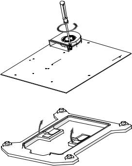
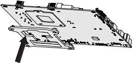
Before installing the boxed thermal solution and processor, please consider integration issues found in the installation notes available at http://support.intel.com/support/ processors. The processor thermal solution requires a Unified Back Plate (UBP) that is to be attached under the main board prior to installing the motherboard inside the chassis. This UBP will be provided in the box with the thermal solution. Images in this manual are only intended as representations. The actual component appearance may vary.
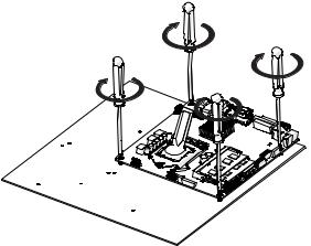
IMPORTANT! Do not fully tighten any heat sink retention screw until all screws are partially engaged.
Avant d’installer le processeur et la solution thermique contenus dans la boîte, veuillez tenir compte des problèmes d’intégration mentionnés dans les notes d’installation disponibles à l’adresse http://support.intel.com/support/processors. Une Unified Back Plate (UBP) doit être fixée sous la carte-mère avant l’installation de la solution thermique du processeur. Cette UBP est fournie dans la boîte avec la solution thermique. Les images figurant dans ce manuel ne sont que des illustrations. L’apparence réelle des composants peut être différente.
IMPORTANT ! Ne serrez aucune vis de maintien du dissipateur de chaleur entièrement avant de les mettre toutes en place.
Informieren Sie sich vor der Installation des Boxed-Kühlers und des Prozessors über die Installationsprobleme, die Sie in den Installationshinweisen unter http://support.intel. com/support/processors finden. Der Prozessor-Kühlkörper erfordert eine einheitliche Montageplatte (Unified Back Plate, UBP), die vor dem Einbau der Hauptplatine im Chassis unter der Hauptplatine angebracht werden muss. Diese UBP wird in der Box mit dem Kühler geliefert. Die Abbildungen in diesem Handbuch dienen nur zur Illustration. Das tatsächliche Aussehen der Komponenten kann davon abweichen.
WICHTIG! Ziehen Sie keine Befestigungsschraube für den Kühlkörper fest an, bevor nicht alle Schrauben lose eingeschraubt wurden.
Antes de instalar el procesador y la solución térmica en caja, tenga en cuenta los problemas de integración descritos en las notas para la instalación que están disponibles en http://support.intel.com/support/processors. La solución térmica del procesador requiere una placa posterior unificada (UBP) que se conecta debajo de la placa base antes de instalar la placa madre dentro del chasis. Esta UBP se suministra en la caja con la solución
térmica. Las imágenes de este manual solo sirven como referencia. El aspecto real del componente puede variar.
¡IMPORTANTE! : No ajuste completamente ningún tornillo de retención del disipador térmico hasta que todos los tornillos se encuentren parcialmente colocados
Antes de instalar a solução térmica e o processador em caixa, leve em consideração os problemas de integração indicados nas notas de instalação disponíveis em http://support. intel.com/support/processors. A solução térmica do processador requer que uma contraplaca unificada (Unified Back Plate, UBP) esteja acoplada embaixo da placa principal antes que a placa mãe seja instalada no gabinete. A UBP é fornecida na caixa junto com a solução térmica. As imagens neste manual são apenas representações. A aparência do componente atual poderá variar.
IMPORTANTE! Não aperte completamente qualquer parafuso de retenção do dissipador de calor até que todos os parafusos estejam parcialmente encaixados.
Prima di installare la soluzione termica e il processore “in box”, prendere in esame i problemi di integrazione riportati nelle note di installazione di sponibili all’indirizzo http:// support.intel.com/support/processors. La soluzione termica del processore necessita di una Unified Back Plate (UBP) collegata sotto la scheda madre prima che questa venga installata nello chassis. L’UBP è inclusa nella confezione della soluzione termica. Le immagini riportate nel presente manuale sono utilizzate a scopo puramente rappresentativo. L’aspetto reale dei componenti può variare.
IMPORTANTE! Non stringere completamente le viti di ritenzione del dissolutore termico fino a quando le viti non siano inserite almeno in parte.
Przed zainstalowaniem dostarczonej w pudełku chłodnicy prosimy uwzględnić kwestie dotyczące integracji opisane w uwagach dostępnych na stronie http:// support.intel.com/support/processors. Chłodnica wymaga przymocowania ujednoliconej tylnej płyty (Unified Back Plate, UBP) pod płytą główną przed zainstalowaniem płyty głównej wewnątrz obudowy. Płyta UBP zostanie dostarczona razem z chłodnicą. Ilustracje zamieszczone w tej instrukcji są przybliżone. Rzeczywisty wygląd komponentów może być odmienny.
WAŻNE! Nie należy dokręcać do końca żadnej ze śrub utrzymujących system chłodzenia, zanim gwinty wszystkich śrub nie zostaną częściowo wkręcone.
Перед установкой поставляемой в штучной упаковке системы охлаждения и процессора внимательно изучите вопросы интеграции,
указанные в замечаниях по установке, которые можно найти по адресу http://support.intel.com/support/processors. Система охлаждения
процессора требует, чтобы унифицированная пластина крепления (UBP) была установлена под материнской платой до установки материнской платы в корпус. UBP будет предоставлена в упаковке вместе с системой охлаждения. Изображения в данном руководстве представлены только в качестве иллюстраций. В действительности внешний вид компонентов может быть иным.
ВАЖНО! Не затягивайте полностью ни один из крепёжных болтов радиатора до тех пор, пока не зафиксируете все болты частично.
http://support.intel.com/ support/processors
(UBP) UBP
絲。
http://support.intel. com/support/processors
(UBP)UBP
,http://support.intel.com/ support/processors
. Unified Back Plate(UBP) .
UBP .. .
!
.
http://support.intel.com/support/processors
て、マウントする前にメインボードの下にUnified Back Plate (UBP)UBP
!
Installation Instructions for the Intel® Thermal Solution HTS1155LP
Cooling Requirement Source: Thermal data based on Intel standard methodology using Intel® Core™ Processor base frequency. Margin determined based on actual test results. Results may vary.
NOTE: Installation instructions are not part of the Three Year Limited Warranty.
REMARQUE: les consignes d’installation ne font pas partie de la garantie limitée de trois ans.
HINWEIS: Die Installationsanleitung ist nicht Teil der eingeschränkten Dreijahresgarantie.
NOTA: Las instrucciones para la instalación no están incluidas en la Garantía limitada de tres años.
OBSERVAÇÃO: As instruções de instalação não fazem parte da garantia limitada de três anos.
NOTA: le istruzioni per l'installazione non sono comprese nella Garanzia limitata di tre anni.
CATATAN: Petunjuk pemasangan ini bukan bagian dari Jaminan Terbatas Tiga Tahun.
UWAGA: Instrukcja instalacji nie jest częścią ograniczonej trzyletniej gwarancji.
ПРИМЕЧАНИЕ: инструкция по монтажу не является частью трехлетней ограниченной гарантии.
: 3 .
3
:
Lưu ý: Hướng dẫn lắp đặt này không phải là một phần trong chế độ Bảo hành Giới hạn Ba Năm.
Make sure the thermal interface material is applied to the top of the CPU Integrated Heat Spreader prior to installation of the heatsink as shown in Step 7. Installation configurations may vary. The actual configuration is defined by the chassis design.
N'oubliez pas d'appliquer la pâte thermique sur le répartiteur de chaleur intégré au CPU avant d’installer le dissipateur thermique comme indiqué à l'étape 7. Les configurations d'installation peuvent différer. La configuration réelle dépend de la conception du châssis.
Stellen Sie sicher, dass vor der Installation des Kühlkörpers, wie in Schritt 7 gezeigt, die Wärmeleitpaste auf das Wärmeverteilblech (Integrated Heat Spreader – IHS) der CPU aufgebracht wird. Die Installationsanordnungen können variieren. Die tatsächliche Anordnung wird durch den Aufbau des Chassis vorgegeben.
Antes de instalar el disipador térmico como se muestra en el Paso 7, asegúrese de aplicar el material de interfaz térmica en la parte superior del difusor de calor integrado a la CPU. La manera de realizar la instalación puede variar y dependerá del diseño del chasis.
Certifique-se de que o material de interface térmica seja aplicado na parte superior do Difusor de Calor Integrado da CPU antes de instalar o dissipador de calor conforme
mostrado no passo 7. As configurações de instalação poderão variar. A configuração final depende do design do gabinete.
Prima dell’installazione del dissipatore di calore integrato (IHS, Integrated Heat Spreader) della CPU assicurarsi che nella parte superiore di questo venga applicata la pasta termoconduttiva, come mostrato nel passaggio 7. Le configurazioni di installazione potrebbero variare. La configurazione effettiva dipende dalla struttura dello chassis.
Przed zainstalowaniem radiatora należy pokryć materiałem termoizolacyjnym górną rozpraszającą ciepło powierzchnię procesora, jak pokazano w czynności 7. Konfiguracja może być rozmaita i zależy od konstrukcji płyty montażowej.
Перед установкой радиатора убедитесь в том, что на поверхность интегрированного теплоотвода процессора нанесен специальный теплопроводящий состав, как показано на иллюстрации к Шагу 7. Конфигурация устанавливаемых элементов может отличаться. Конкретная конфигурация определяется конструкцией корпуса.
7 CPU
CPU7
7 CPU
. .
.
7 CPU

http://www.intel.com/go/aio |
http://www.intel.com/go/aio
1
2
http://www.intel.com/go/aio
3
4
http://www.intel.com/go/aio
5
http://www.intel.com/go/aio
6
http://www.intel.com/go/aio
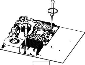
7
A.Partially tighten the screws
A.Serrez partiellement les vis
A.Ziehen Sie die Schrauben leicht an
A.Ajuste un poco los tornillos
A.Aperte parcialmente os parafusos
A.Serrare parzialmente le viti
A.Dokręcić śruby do pierwszego oporu
A.Наживите винты
http://www.intel.com/go/aio
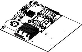
8
 M2.5 * 0.45
B. Move the heat exchanger to close the gap to the blower
B.Déplacez l'échangeur thermique de façon à l’accoler au ventilateur
B.Verschieben Sie den Wärmetauscher, um die Lücke zum Lüfter zu schließen
B. Mueva el intercambiador de calor para acercarlo al ventilador B. Coloque o trocador de calor em posição adjacente à ventoinha
B.Spostare lo scambiatore di calore in modo da colmare lo spazio verso il soffiatore
B.Przesunąć wymiennik ciepła, aby zakryć szczelinę do dmuchawy
B.Прижмите теплообменник к вентилятору, устранив зазор
B.
B.
B.
http://www.intel.com/go/aio
9
C. Fully tighten the screws
C. Serrez complètement les vis
C. Ziehen Sie die Schrauben vollständig fest C. Ajuste completamente los tornillos
C. Aperte completamente os parafusos C. Stringere completamente le viti
C. Całkowicie dokręcić śruby
C. Полностью затяните винты
C.
C.
C.
C.
http://www.intel.com/go/aio
10
11
D. Plug in the fan cable connector D. Connectez le câble du ventilateur
D. Stecken Sie den Steckverbinder des Gebläsekabels ein D. Enchufe el conector del cable del ventilador
D. Ligue o conector do cabo do ventilador
D. Collegare il connettore del cavo della ventola
D. Podłączyć kabel zasilania wentylatora
D. Подсоедините разъем кабеля вентилятора
D.
D.
D.
D.
 Loading...