

Page 1
OPERATING MANUAL
XTM/2
Deposition Monitor
IPN 074-186
Page 2

Page 3

OPERATING MANUAL
XTM/2
Deposition Monitor
IPN 074-186S
TWO TECHNOLOGY PLACE
EAST SYRACUSE, NY 13057-9714 USA
Phone: +315.434.1100
Fax: +315.437.3803
Email: reachus@inficon.com
VISIT US ON THE WEB AT www.inficon.com
©2001 INFICON 092304
ALTE LANDSTRASSE 6
LI-9496 BALZERS, LIECHTENSTEIN
Phone: +423.388.3111
Fax: +423.388.3700
Email: reach.liechtenstein@ inficon.com
BONNER STRASSE 498
D-50968 COLOGNE, GERMANY
Phone: +49.221.347.40
Fax: +49.221.347.41429
Email: reach.germany@i nficon.com
Page 4

Trademarks
The trademarks of the products mentioned in this manual are held by the companies that
produce them.
INFICON®, CrystalSix® are trademarks of INFICON Inc.
All other brand and product names are trademarks or registered trademarks of their respective companies.
The information contained in this manual is believed to be accurate and reliable. However, INFICON assumes
no responsibility for its use and shall not be liable for any special, incidental, or consequential damages related
to the use of this product.
©2001 All rights reserved.
Reproduction or adaptation of any part of this document without permission is unlawful.
Page 5

DECLARATION
OF
CONFORMITY
This is to certify that this equipment, designed and manufactured by:
INFICON Inc.
2 Technology Place
East Syracuse, NY 13057
USA
meets the essential safety requirements of the European Union and is placed on the
market accordingly. It has been constructed in accordance with good engineering
practice in safety matters in force in the Community and does not endanger the safety
of persons, domestic animals or property when properly installed and maintained and
used in applications for which it was made.
Equipment Description: XTM/2 Deposition Monitor, including the Oscillator
Package and Crystal Sensor as properly installed.
Applicable Directives: 73/23/EEC as amended by 93/68/EEC
89/336/EEC as amended by 93/68/EEC
Applicable Standards: EN 61010-1 : 1993, Fixed Equipment
EN 55011, Group 1, Class A : 1991
EN 50082-2 : 1995
CE Implementation Date: January 3, 1995
Revised to include EMC Directive: January 2, 1997
Authorized Representative: Gary W. Lewis
Vice President - Quality Assurance
INFICON Inc.
ANY QUESTIONS RELATIVE TO THIS DECLARATION OR TO THE SAFETY OF INFICON'S PRODUCTS SHOULD BE
DIRECTED, IN WRITING, TO THE QUALITY ASSURANCE DEPARTMENT AT THE ABOVE ADDRESS.
11/14/01
Page 6

Page 7

Registration Card
Thank you for selecting INFICON instrumentation.
®
Please fill out and return this postage paid card as soon as possible.
Model
Serial #
Name
Title
Company
Address
City
Country
State Zip
Fax# Email
Bldg./MS
Phone #
Your help is very important in our continuing efforts to improve our manuals.
Using the table below, please circle the appropriate rank for each aspect.
In the Importance column, please indicate the importance of each aspect.
Manual Title
Very
VD
VD
074-
Dissatisfied
D
D
No
Opinion
NO
NO
Satisfied
S
S
Very
Satisfied
VS
VS
(ranked from
1 to 5, where
1 is low and
Part # (see Title Page)
Aspect
Found everything
I needed
Easy to read
Dissatisfied
Importance
5 is high)
Easy to use
Relevant to
my work
Accurate
information
Well-written
Well-organized
Technical Enough
Helped me
solve problems
VD
VD
VD
VD
VD
VD
VD
D
D
D
D
D
D
D
NO
NO
NO
NO
NO
NO
NO
S
S
S
S
S
S
If you have additional comments, please contact INFICON.
TWO TECHNOLOGY PLACE
EAST SYRACUSE, NY 13057-9714 USA
Phone: +315.434.1100
Fax: +315.437.3803
Email: reachus@inficon.com
VISIT US ON THE WEB AT www.inficon.com
ALTE LANDSTRASSE 6
LI-9496 BALZERS, LIECHTEN STEIN
Phone: +423.388.3111
Fax: +423.388.3700
Email: reach.liechtenstein@inficon.com
VS
S
VS
VS
VS
VS
VS
VS
®
BONNER STRASSE 498
D-50968 COLOGNE, GERMANY
Phone: +49.221.347.40
Fax: +49.221.347.41429
Email: reach.germany@inficon.com
Page 8

BUSINESS REPLY MAIL
FIRST CLASS PERMIT NO. 49 EAST SYRACUSE, NEW YORK
POSTAGE WILL BE PAID BY ADDRESSEE
INFICON INC.
Two Tech no logy Plac e
East Syracuse, New York 13057-9714
Page 9

Warranty
WARRANTY AND LIABILITY - LIMITATION: Seller warrants the products
manufactured by it, or by an affiliated company and sold by it, and described on
the reverse hereof, to be, for the period of warranty coverage specified below, free
from defects of materials or workmanship under normal proper use and service.
The period of warranty coverage is specified for the respective products in the
respective Seller instruction manuals for those products but shall in no event
exceed one (1) year from the date of shipment thereof by Seller. Seller's liability
under this warranty is limited to such of the above products or parts thereof as are
returned, transportation prepaid, to Seller's plant, not later than thirty (30) days
after the expiration of the period of warranty coverage in respect thereof and are
found by Seller's examination to have failed to function properly because of
defective workmanship or materials and not because of improper installation or
misuse and is limited to, at Seller's election, either (a) repairing and returning the
product or part thereof, or (b) furnishing a replacement product or part thereof,
transportation prepaid by Seller in either case. In the event Buyer discovers or
learns that a product does not conform to warranty, Buyer shall immediately notify
Seller in writing of such non-conformity, specifying in reasonable detail the nature
of such non-conformity. If Seller is not provided with such written notification,
Seller shall not be liable for any further damages which could have been avoided if
Seller had been provided with immediate written notification.
THIS WARRANTY IS MADE AND ACCEPTED IN LIEU OF ALL OTHER
WARRANTIES, EXPRESS OR IMPLIED, WHETHER OF MERCHANTABILITY OR
OF FITNESS FOR A PARTICULAR PURPOSE OR OTHERWISE, AS BUYER'S
EXCLUSIVE REMEDY FOR ANY DEFECTS IN THE PRODUCTS TO BE SOLD
HEREUNDER. All other obligations and liabilities of Seller, whether in contract or
tort (including negligence) or otherwise, are expressly EXCLUDED. In no event
shall Seller be liable for any costs, expenses or damages, whether direct or
indirect, special, incidental, consequential, or other, on any claim of any defective
product, in excess of the price paid by Buyer for the product plus return
transportation charges prepaid.
No warranty is made by Seller of any Seller product which has been installed,
used or operated contrary to Seller's written instruction manual or which has been
subjected to misuse, negligence or accident or has been repaired or altered by
anyone other than Seller or which has been used in a manner or for a purpose for
which the Seller product was not designed nor against any defects due to plans or
instructions supplied to Seller by or for Buyer.
This manual is intended for private use by INFICON® Inc. and its customers.
Contact INFICON before reproducing its contents.
NOTE: These instructions do not provide for every contingency that may arise in
connection with the installation, operation or maintenance of this equipment.
Should you require further assistance, please contact INFICON.
TWO TECHNOLOGY PLACE
EAST SYRACUSE, NY 13057-9714 USA
Phone: +315.434.1100
Fax: +315.437.3803
Email: reachus@inficon.com
VISIT US ON THE WEB AT www.inficon.com
ALTE LANDSTRASSE 6
LI-9496 BALZERS, LIECHTEN STEIN
Phone: +423.388.3111
Fax: +423.388.3700
Email: reach.liechtenstein@inficon.com
BONNER STRASSE 498
D-50968 COLOGNE, GERMANY
Phone: +49.221.347.40
Fax: +49.221.347.41429
Email: reach.germany@inficon.com
Page 10

Page 11

XTM/2 Operating Manual
Table Of Contents
Chapter 1
Introduction and Specifications
1.1 Instrument Safety . . . . . . . . . . . . . . . . . . . . . . . . . . . . . . . . . . . . . . . . . 1-1
1.1.1 Notes, Cautions, Warnings . . . . . . . . . . . . . . . . . . . . . . . . . . . . . . . . . .1-1
1.1.2 General Safety Information . . . . . . . . . . . . . . . . . . . . . . . . . . . . . . . . . .1-2
1.1.3 Earth Ground. . . . . . . . . . . . . . . . . . . . . . . . . . . . . . . . . . . . . . . . . . . . .1-3
1.1.4 Main Power Connection . . . . . . . . . . . . . . . . . . . . . . . . . . . . . . . . . . . .1-4
1.2 Introduction to the Instrument . . . . . . . . . . . . . . . . . . . . . . . . . . . . . . . .1-5
1.3 Specifications . . . . . . . . . . . . . . . . . . . . . . . . . . . . . . . . . . . . . . . . . . . . 1-6
1.3.1 Specifications XTM/2. . . . . . . . . . . . . . . . . . . . . . . . . . . . . . . . . . . . . . . 1-6
1.3.1.1 General. . . . . . . . . . . . . . . . . . . . . . . . . . . . . . . . . . . . . . . . . . . . . . . . .1-6
1.3.1.2 Measurement . . . . . . . . . . . . . . . . . . . . . . . . . . . . . . . . . . . . . . . . . . . .1-6
1.3.1.3 Recorder Output . . . . . . . . . . . . . . . . . . . . . . . . . . . . . . . . . . . . . . . . . . 1-6
1.3.1.4 Input/Output . . . . . . . . . . . . . . . . . . . . . . . . . . . . . . . . . . . . . . . . . . . . .1-7
1.3.1.5 Display . . . . . . . . . . . . . . . . . . . . . . . . . . . . . . . . . . . . . . . . . . . . . . . . .1-7
1.3.1.6 Process Variable Storage . . . . . . . . . . . . . . . . . . . . . . . . . . . . . . . . . . . 1-7
1.3.1.7 Hardware Interface . . . . . . . . . . . . . . . . . . . . . . . . . . . . . . . . . . . . . . . . 1-7
1.3.1.8 Operation . . . . . . . . . . . . . . . . . . . . . . . . . . . . . . . . . . . . . . . . . . . . . . .1-8
1.3.1.9 Mechanical . . . . . . . . . . . . . . . . . . . . . . . . . . . . . . . . . . . . . . . . . . . . . . 1-8
1.3.2 Transducer Specifications (optional) . . . . . . . . . . . . . . . . . . . . . . . . . . .1-8
1.3.3 XIU (Crystal Interface Unit) Specifications . . . . . . . . . . . . . . . . . . . . . . . 1-9
1.4 Guide to the Use of the Manual. . . . . . . . . . . . . . . . . . . . . . . . . . . . . . .1-9
1.5 How To Contact Customer Support. . . . . . . . . . . . . . . . . . . . . . . . . . . 1-10
1.5.1 Application Support. . . . . . . . . . . . . . . . . . . . . . . . . . . . . . . . . . . . . . .1-10
1.5.2 Field Service and Repair Support . . . . . . . . . . . . . . . . . . . . . . . . . . . .1-10
IPN 074-186S
1.5.3 Returning Your Instrument . . . . . . . . . . . . . . . . . . . . . . . . . . . . . . . . .1-10
Chapter 2
Quick Use Guide
2.1 Unpacking, Initial Inspection and Inventory . . . . . . . . . . . . . . . . . . . . . .2-1
2.1.1 Unpacking and Inspection Procedures . . . . . . . . . . . . . . . . . . . . . . . . .2-1
2.1.2 Inventory. . . . . . . . . . . . . . . . . . . . . . . . . . . . . . . . . . . . . . . . . . . . . . . .2-1
2.1.2.1 XTM/2 System Configuration. . . . . . . . . . . . . . . . . . . . . . . . . . . . . . . . .2-2
2.1.2.2 Ship Kit - XTM/2 . . . . . . . . . . . . . . . . . . . . . . . . . . . . . . . . . . . . . . . . . .2-2
2.2 Voltage Selection . . . . . . . . . . . . . . . . . . . . . . . . . . . . . . . . . . . . . . . . . 2-3
2.3 Installation Guide and Schematic . . . . . . . . . . . . . . . . . . . . . . . . . . . . .2-7
TOC - 1
Page 12

XTM/2 Operating Manual
2.4 XTM/2 Front Panel Description. . . . . . . . . . . . . . . . . . . . . . . . . . . . . . . 2-9
2.4.1 XTM/2 Front Control Panel Description . . . . . . . . . . . . . . . . . . . . . . . . 2-9
2.4.2 XTM/2 Display Description . . . . . . . . . . . . . . . . . . . . . . . . . . . . . . . . . 2-11
2.5 XTM/2 Rear Panel Description . . . . . . . . . . . . . . . . . . . . . . . . . . . . . . 2-13
2.5.1 Power Module . . . . . . . . . . . . . . . . . . . . . . . . . . . . . . . . . . . . . . . . . . 2-14
2.5.2 Configuration Switches 1 & 2 . . . . . . . . . . . . . . . . . . . . . . . . . . . . . . . 2-15
2.5.3 Grounding Stud . . . . . . . . . . . . . . . . . . . . . . . . . . . . . . . . . . . . . . . . . 2-17
2.5.4 System I/O . . . . . . . . . . . . . . . . . . . . . . . . . . . . . . . . . . . . . . . . . . . . . 2-18
2.5.5 RS232 . . . . . . . . . . . . . . . . . . . . . . . . . . . . . . . . . . . . . . . . . . . . . . . . 2-19
2.5.6 Sensor . . . . . . . . . . . . . . . . . . . . . . . . . . . . . . . . . . . . . . . . . . . . . . . . 2-20
2.5.7 International Warning Symbol for
Users and Technicians. . . . . . . . . . . . . . . . . . . . . . . . . . . . . . . . . . . . 2-20
2.5.8 Recorder . . . . . . . . . . . . . . . . . . . . . . . . . . . . . . . . . . . . . . . . . . . . . . 2-20
2.5.9 Comm. Option . . . . . . . . . . . . . . . . . . . . . . . . . . . . . . . . . . . . . . . . . . 2-21
2.5.10 Manufacturer’s Identific ation and
Serial Number Plate. . . . . . . . . . . . . . . . . . . . . . . . . . . . . . . . . . . . . . 2-21
2.6 Operation as a Deposition Monitor . . . . . . . . . . . . . . . . . . . . . . . . . . . 2-22
2.6.1 Monitoring - Systems Without a Source Shutter . . . . . . . . . . . . . . . . . 2-22
2.6.2 Monitoring - Systems with a Source Shutter. . . . . . . . . . . . . . . . . . . . 2-23
2.6.3 Rate Sampling . . . . . . . . . . . . . . . . . . . . . . . . . . . . . . . . . . . . . . . . . . 2-23
2.7 Nontraditional Applications. . . . . . . . . . . . . . . . . . . . . . . . . . . . . . . . . 2-24
2.7.1 Etching. . . . . . . . . . . . . . . . . . . . . . . . . . . . . . . . . . . . . . . . . . . . . . . . 2-24
2.7.2 Immersion in Liquids . . . . . . . . . . . . . . . . . . . . . . . . . . . . . . . . . . . . . 2-24
2.7.3 Biological . . . . . . . . . . . . . . . . . . . . . . . . . . . . . . . . . . . . . . . . . . . . . . 2-25
2.7.4 Measurement of Liquids. . . . . . . . . . . . . . . . . . . . . . . . . . . . . . . . . . . 2-25
2.7.5 Use as a Frequency Counter . . . . . . . . . . . . . . . . . . . . . . . . . . . . . . . 2-25
2.7.6 Contamination Detection . . . . . . . . . . . . . . . . . . . . . . . . . . . . . . . . . . 2-26
Chapter 3
TOC - 2
Installation
3.1 Installing the Instrument - Details . . . . . . . . . . . . . . . . . . . . . . . . . . . . . 3-1
3.1.1 Control Unit Installation . . . . . . . . . . . . . . . . . . . . . . . . . . . . . . . . . . . . 3-1
3.2 Electrical Grounding and Shielding Requirements . . . . . . . . . . . . . . . . 3-1
3.2.1 Verifying / Establishing Earth Ground. . . . . . . . . . . . . . . . . . . . . . . . . . 3-2
3.2.2 Connections to Earth Ground. . . . . . . . . . . . . . . . . . . . . . . . . . . . . . . . 3-2
3.2.3 Minimizing Noise Pickup from External Cabling . . . . . . . . . . . . . . . . . . 3-3
3.3 Connection to Rear Panel . . . . . . . . . . . . . . . . . . . . . . . . . . . . . . . . . . 3-4
3.3.1 The BNC Connectors . . . . . . . . . . . . . . . . . . . . . . . . . . . . . . . . . . . . . . 3-4
3.3.2 The "D" Shell Connectors. . . . . . . . . . . . . . . . . . . . . . . . . . . . . . . . . . . 3-4
3.4 Sensor Selection Guide . . . . . . . . . . . . . . . . . . . . . . . . . . . . . . . . . . . . 3-6
3.5 Guidelines for Transducer Installation . . . . . . . . . . . . . . . . . . . . . . . . . 3-7
IPN 074-186S
Page 13

XTM/2 Operating Manual
3.5.1 Sensor Installation. . . . . . . . . . . . . . . . . . . . . . . . . . . . . . . . . . . . . . . . . 3-7
3.5.2 CrystalSix . . . . . . . . . . . . . . . . . . . . . . . . . . . . . . . . . . . . . . . . . . . . . .3-10
3.5.3 Check List for Transducer Installation . . . . . . . . . . . . . . . . . . . . . . . . .3-11
3.6 Use of the Test Mode . . . . . . . . . . . . . . . . . . . . . . . . . . . . . . . . . . . . .3-11
3.6.1 Operational Test . . . . . . . . . . . . . . . . . . . . . . . . . . . . . . . . . . . . . . . . . 3-12
3.7 Input and Output Details . . . . . . . . . . . . . . . . . . . . . . . . . . . . . . . . . . .3-14
3.7.1 Relays. . . . . . . . . . . . . . . . . . . . . . . . . . . . . . . . . . . . . . . . . . . . . . . . .3-14
3.7.2 Inputs . . . . . . . . . . . . . . . . . . . . . . . . . . . . . . . . . . . . . . . . . . . . . . . . .3-15
3.7.3 Chart Recorder . . . . . . . . . . . . . . . . . . . . . . . . . . . . . . . . . . . . . . . . . . 3-15
3.8 Computer Communications . . . . . . . . . . . . . . . . . . . . . . . . . . . . . . . . .3-16
3.8.1 Communications Setup . . . . . . . . . . . . . . . . . . . . . . . . . . . . . . . . . . . . 3-16
3.8.1.1 IEEE Settings for a National Instruments IEEE-GPIB Board . . . . . . . .3-17
3.8.2 Basic Command Structure . . . . . . . . . . . . . . . . . . . . . . . . . . . . . . . . . .3-18
3.8.3 Service Requests and Message Available. . . . . . . . . . . . . . . . . . . . . .3-20
3.8.4 Datalogging. . . . . . . . . . . . . . . . . . . . . . . . . . . . . . . . . . . . . . . . . . . . . 3-21
3.8.5 Computer Command Details . . . . . . . . . . . . . . . . . . . . . . . . . . . . . . . .3-22
3.8.5.1 Echo Command. . . . . . . . . . . . . . . . . . . . . . . . . . . . . . . . . . . . . . . . . .3-22
3.8.5.2 Hello Command. . . . . . . . . . . . . . . . . . . . . . . . . . . . . . . . . . . . . . . . . . 3-22
3.8.5.3 Query Command. . . . . . . . . . . . . . . . . . . . . . . . . . . . . . . . . . . . . . . . .3-22
3.8.5.4 Update Command . . . . . . . . . . . . . . . . . . . . . . . . . . . . . . . . . . . . . . . .3-23
3.8.5.5 Status Command. . . . . . . . . . . . . . . . . . . . . . . . . . . . . . . . . . . . . . . . .3-23
3.8.5.6 Remote Command . . . . . . . . . . . . . . . . . . . . . . . . . . . . . . . . . . . . . . .3-26
3.8.6 Examples of RS232 Programs. . . . . . . . . . . . . . . . . . . . . . . . . . . . . . .3-27
3.8.6.1 Example of SEMI II Program. . . . . . . . . . . . . . . . . . . . . . . . . . . . . . . .3-29
3.8.7 Example of IEEE488 Program. . . . . . . . . . . . . . . . . . . . . . . . . . . . . . .3-31
Chapter 4
Programming System Operation Details
IPN 074-186S
4.1 State and Measurement System Sequencing . . . . . . . . . . . . . . . . . . . .4-1
4.2 State Descriptions. . . . . . . . . . . . . . . . . . . . . . . . . . . . . . . . . . . . . . . . . 4-3
4.3 Parameter Limits. . . . . . . . . . . . . . . . . . . . . . . . . . . . . . . . . . . . . . . . . . 4-4
4.4 Crystal Fail . . . . . . . . . . . . . . . . . . . . . . . . . . . . . . . . . . . . . . . . . . . . . .4-4
4.5 Crystal Fail Inhibit . . . . . . . . . . . . . . . . . . . . . . . . . . . . . . . . . . . . . . . . .4-5
4.6 Crystal Life and Starting Frequency. . . . . . . . . . . . . . . . . . . . . . . . . . . . 4-5
Chapter 5
Calibration and Measurement
5.1 Importance of Density, Tooling and Z-ratio . . . . . . . . . . . . . . . . . . . . . .5-1
5.2 Determining Density . . . . . . . . . . . . . . . . . . . . . . . . . . . . . . . . . . . . . . . 5-1
5.3 Determining Tooling . . . . . . . . . . . . . . . . . . . . . . . . . . . . . . . . . . . . . . .5-2
TOC - 3
Page 14

XTM/2 Operating Manual
5.4 Laboratory Determination of Z-ratio . . . . . . . . . . . . . . . . . . . . . . . . . . . 5-3
5.5 Measurement Theory . . . . . . . . . . . . . . . . . . . . . . . . . . . . . . . . . . . . . . 5-4
5.5.1 Basics . . . . . . . . . . . . . . . . . . . . . . . . . . . . . . . . . . . . . . . . . . . . . . . . . 5-4
5.5.2 Monitor Crystals. . . . . . . . . . . . . . . . . . . . . . . . . . . . . . . . . . . . . . . . . . 5-6
5.5.3 Period Measurement Technique. . . . . . . . . . . . . . . . . . . . . . . . . . . . . . 5-8
5.5.4 Z-Match Technique . . . . . . . . . . . . . . . . . . . . . . . . . . . . . . . . . . . . . . . 5-9
5.5.5 Active Oscillator . . . . . . . . . . . . . . . . . . . . . . . . . . . . . . . . . . . . . . . . . . 5-9
5.5.6 ModeLock Oscillator. . . . . . . . . . . . . . . . . . . . . . . . . . . . . . . . . . . . . . 5-12
Chapter 6
Adjustments and Problems
6.1 LCD Contrast Adjustment. . . . . . . . . . . . . . . . . . . . . . . . . . . . . . . . . . . 6-1
6.2 Error Messages . . . . . . . . . . . . . . . . . . . . . . . . . . . . . . . . . . . . . . . . . . 6-1
6.2.1 Powerup Errors . . . . . . . . . . . . . . . . . . . . . . . . . . . . . . . . . . . . . . . . . . 6-1
6.2.2 Parameter Update Errors . . . . . . . . . . . . . . . . . . . . . . . . . . . . . . . . . . . 6-2
6.2.3 Other Errors . . . . . . . . . . . . . . . . . . . . . . . . . . . . . . . . . . . . . . . . . . . . . 6-2
6.3 Troubleshooting Guide. . . . . . . . . . . . . . . . . . . . . . . . . . . . . . . . . . . . . 6-2
6.3.1 Major Instrument Components, Assemblies and Mating Connectors. . . 6-3
6.3.2 Troubleshooting the Instrument . . . . . . . . . . . . . . . . . . . . . . . . . . . . . . 6-4
6.3.3 Troubleshooting Transducers/Sensors . . . . . . . . . . . . . . . . . . . . . . . . . 6-7
6.3.4 Troubleshooting Computer Communications . . . . . . . . . . . . . . . . . . . 6-11
6.3.5 Leaf Spring Concerns. . . . . . . . . . . . . . . . . . . . . . . . . . . . . . . . . . . . . 6-14
6.4 Replacing the Crystal. . . . . . . . . . . . . . . . . . . . . . . . . . . . . . . . . . . . . 6-15
6.4.1 Standard and Compact. . . . . . . . . . . . . . . . . . . . . . . . . . . . . . . . . . . . 6-16
6.4.2 Shuttered and Dual Sensors. . . . . . . . . . . . . . . . . . . . . . . . . . . . . . . . 6-17
6.4.3 Bakeable Sensor . . . . . . . . . . . . . . . . . . . . . . . . . . . . . . . . . . . . . . . . 6-17
6.4.4 Sputtering Sensor . . . . . . . . . . . . . . . . . . . . . . . . . . . . . . . . . . . . . . . 6-18
6.4.5 Crystal Snatcher. . . . . . . . . . . . . . . . . . . . . . . . . . . . . . . . . . . . . . . . . 6-19
6.5 Crystal Sensor Emulator
IPN 760-601-G1 or 760-601-G2 . . . . . . . . . . . . . . . . . . . . . . . . . . . . . 6-20
6.5.1 Diagnostic Procedures . . . . . . . . . . . . . . . . . . . . . . . . . . . . . . . . . . . . 6-21
6.5.1.1 Measurement System Diagnostic Procedure . . . . . . . . . . . . . . . . . . . 6-21
6.5.1.2 Feed-Through Or In-Vacuum Cable
Diagnostic Procedure. . . . . . . . . . . . . . . . . . . . . . . . . . . . . . . . . . . . . 6-22
6.5.1.3 Sensor Head Or Monitor Crystal
Diagnostic Procedure. . . . . . . . . . . . . . . . . . . . . . . . . . . . . . . . . . . . . 6-23
IPN 074-186S
6.5.1.4 System Diagnostics Pass But
6.5.3.1 Compatible Sensor Heads . . . . . . . . . . . . . . . . . . . . . . . . . . . . . . . . . 6-25
TOC - 4
Crystal Fail Message Remains. . . . . . . . . . . . . . . . . . . . . . . . . . . . . . 6-24
6.5.2 % XTAL Life. . . . . . . . . . . . . . . . . . . . . . . . . . . . . . . . . . . . . . . . . . . . 6-24
6.5.3 Sensor Cover Connection . . . . . . . . . . . . . . . . . . . . . . . . . . . . . . . . . 6-25
Page 15

6.5.3.2 Incompatible Sensor Heads. . . . . . . . . . . . . . . . . . . . . . . . . . . . . . . . .6-25
6.5.4 Specifications . . . . . . . . . . . . . . . . . . . . . . . . . . . . . . . . . . . . . . . . . . .6-26
Appendix A
Index
XTM/2 Operating Manual
Table of Densities and Z-ratios
IPN 074-186S
TOC - 5
Page 16

XTM/2 Operating Manual
TOC - 6
IPN 074-186S
Page 17

Introduction and Specifications
1.1 Instrument Safety
1.1.1 Notes, Cautions, Warnings
When using this manual, please pay attention to the NOTES, CAUTIONS and
WARNINGS found throughout. For the purposes of this manual they are
defined as follows:
NOTE: Pertinent information that is useful in achieving maximum instrument
efficiency when followed.
CAUTION
Failure to heed these messages could result in damage
to the instrument or the loss o f data.
XTM/2 Operating Manual
Chapter 1
WARNING
Failure to heed these messages coul d result in
personal injury.
WARNING
Dangerous voltages are present. Failure to heed these
messages could result in personal injury.
IPN 074-186S
1 - 1
Page 18
XTM/2 Operating Manual
1.1.2 General Safety Information
WARNING
There are no user serviceabl e compon ents within the
instrument case.
Potentially lethal voltages are present when the line
cord or system I/O are connected.
Refer all maintenance to qualified personnel.
CAUTION
This instrument contains delicate circuitry which is
susceptible to transient power line voltages.
Disconnect the line cord whenever making any
interface connections. Refer all mainte nance to
qualified personnel.
1 - 2
IPN 074-186S
Page 19

1.1.3 Earth Ground
This instrument is connected to earth via a sealed three-core (three-conductor)
power cable, which must be plugged into a socket outlet with a protective earth
terminal. Extension cables must always have three condu ctors, inclu ding a
protective earth conductor.
WARNING
XTM/2 Operating Manual
Never interrupt the protective earth circuit.
Any interruption of the protective earth connection
inside or outside the instrument, or disconnection of
the protective earth terminal is likely to make the
instrument dangerous.
This symbol indicates where the protective earth
ground is connected inside the instrume nt. Never
unscrew or loosen this connection .
IPN 074-186S
1 - 3
Page 20

XTM/2 Operating Manual
1.1.4 Main Power Connection
WARNING
This instrument has a line voltage present on the
primary circuits whenever it is plugged into a main
power source.
Never remove the covers from the instrument during
normal operation.
There is no operator serviceable items within this
instrument.
Removal of the top or bottom covers must be done
only by a technically qualified person.
In order to comply with accepted safety standards, this
instrument must be installed into a rack system which
contains a mains switch. This switch must break both
sides of the line when it is open and it must not
disconnect the safety ground.
1 - 4
IPN 074-186S
Page 21

1.2 Introduction to the Instrument
The XTM/2 is an economical quartz crystal transducer type depo sition/etch
process monitor that incorporates the patented (US#5,117,192 — May
27,1992) ModeLock measurement system. This inn ovative sy stem provide s
process security, measurement speed and precision at a level that no active
oscillator based instrument can provide.Th e Liquid Crystal Display of the
XTM/2 is easily read and keeps the operator continuously informed with
pertinent deposition data including rate, thickne ss and elapsed time. Special
messages such as Crystal Fail, achievement of setp oints, measuremen t units
or etch mode are clearly presented to reduce operator uncertainty and eliminate
the possibility of costly mistakes. Basic instrument operat ion is easily verified
with a built-in test mode and preprogrammed parameters.The se t up and
storage of nine different process variable sets is provided.The RATE and
THICKNESS displays as well as the limit parameters may be read and
programmed in the traditional kÅ units or directly in mass (mg, µgm,ngm).
All units come with RS232 (and support Data Rates to 9,600 Baud).The SECSII
protocol is supported.The optional computer interface is IEEE-488. Four relays
are used to manipulate various external devices such as source and sensor
shutters, heaters or valves.There are five input line s to provide the ab ility to
sense and react to discrete external signals.The se instruments are fully
compatible with the complete family of INFICON transducers, excluding Dual
and CrystalSix®.
XTM/2 Operating Manual
IPN 074-186S
1 - 5
Page 22

XTM/2 Operating Manual
1.3 Specifications
At the time of this manual’s writing, the specifications for perform ance are as
published below. INFICON continuously improves its products, affecting the
instrument’s performance.
1.3.1 Specifications XTM/2
1.3.1.1 General
Usage . . . . . . . . . . . . . . . . . . . . . .Indoor use only.
Altitude Range. . . . . . . . . . . . . . . .Up to 2000 m (6,561 ft)
Pollution Degree . . . . . . . . . . . . . .1—No pollution occ urs
Overvoltage Category . . . . . . . . . .2—Local level, appliances, etc.
Cleaning . . . . . . . . . . . . . . . . . . . .The unit enclosure can be safely cleaned
with a mild detergent or spray cleaner
designed for that purpose. Care should be
taken to prevent any cleaner from entering
the unit.
1.3.1.2 Measurement
Crystal Range & Precision. . . . . . .6.0 to 5.0 MHz +/- 0.1 Hz
Thickness & Rate Resolution* . . . .0. 123Å (per 250 msec samp le)
Thickness accuracy . . . . . . . . . . . .0.5%
Measurements/second . . . . . . . . . .4 max., user selectable multiple
1.3.1.3 Recorder Output
Voltage . . . . . . . . . . . . . . . . . . . . .0 to ±10 v
Resolution . . . . . . . . . . . . . . . . . . .13 bits over full range
Update Rate . . . . . . . . . . . . . . . . .4 Hz
Function. . . . . . . . . . . . . . . . . . . . .Rat e / Thickness / Ma ss
(per 250 msec sample)
* Material density = 1.0; Z-ratio = 1.0;
crystal frequency = 6 MHz.
Å/S/M = Angstroms/second/measurement.
measurement averaging to 16 seconds in
four ranges.
IPN 074-186S
(one reserved for sign)
1 - 6
Maximum Load . . . . . . . . . . . . . . .2.0 KOhm (100 Ohm internal impedance)
Page 23

1.3.1.4 Input/Output
Inputs . . . . . . . . . . . . . . . . . . . . . . 5 TTL inputs
Outputs . . . . . . . . . . . . . . . . . . . . . 4 SPST 2.5 amp relays rated
Scan/Change Rate . . . . . . . . . . . . 4 Hz
1.3.1.5 Display
Type . . . . . . . . . . . . . . . . . . . . . . . 2x multiplexed custom LCD
Thickness Resolution* . . . . . . . . . 1 Å
Rate Resolution* . . . . . . . . . . . . . .1 Å for 1 to 99.9 Å/sec
Update Rate . . . . . . . . . . . . . . . . . 1 Hz
XTM/2 Operating Manual
@ 30 V(dc) / 30 V(ac) / 42 V(peak) max.
1 Å for 100 to 999 Å/sec
* Other units appropriately scaled.
Enhanced resolution is achieved when
multiple measurement averaging is
employed.
1.3.1.6 Process Variable Storage
Quantity . . . . . . . . . . . . . . . . . . . . 9 sets
Variables per set. . . . . . . . . . . . . . 6
1.3.1.7 Hardware Interface
Sensors . . . . . . . . . . . . . . . . . . . . 1, 15 pin D-Sub type
I/O
Standard (inputs/outputs) . . . . 5/4
Optional . . . . . . . . . . . . . . . . . None
Communications
Standard . . . . . . . . . . . . . . . . . RS232C, 9 Pin D-Sub type
Optional . . . . . . . . . . . . . . . . . IEEE-488
IPN 074-186S
Chart Recorder. . . . . . . . . . . . . . . BNC
1 - 7
Page 24

XTM/2 Operating Manual
1.3.1.8 Operation
Power Requirements
"115 V" input range. . . . . . . . . .90 to 132 V(ac), 49 to 61 Hz, 45 VA max.
fused at 3/8 Amp Type T fuse
"230 V" input range . . . . . . . . .180 to 264 V(ac), 49 to 61 Hz, 45 VA max.
fused at 3/16 Amp Type T fuse
Operating Temperature . . . . . . . . .0 to 50 °C (32 to 122 °F)
1.3.1.9 Mechanical
Size . . . . . . . . . . . . . . . . . . . . . . . .3.5" H x 8" W x 12" D
(89 mm H x 203 mm W x 305 D mm)
Weight. . . . . . . . . . . . . . . . . . . . . .6 lb. (2.7 kg)
1.3.2 Transducer Specifications (optional)
Max. Bakeout
Temperature*
Standard Sensor 130 °C 1.063" x 1.33" x .69" high
Standard Sensor
with Shutter
Sputtering Sensor 105 °C 1.36" dia. x .47" high
Compact Sensor 130 °C 1.11" x 1.06" x 1.06" high
Compact Sensor
with Shutter
UHV Bakeable
Sensor
UHV Bakeable
Sensor with Shutter
Shutter Assembly 400 °C two models available N/A 300-series SS 750-210-G1
*For Bake only; waterflow is required for actual deposition monitoring. These temperatures are conservative maximum
device temperatures, limited by the properties of Teflon (PTFE) at higher temperatures. In usage, the water cooling allows
operation in environments that are significantly elevated, without deleterious affects.
130 °C 1.06" x 2.24" x .69" high
130 °C 2.08" x 1.62" x 1.83" high
450 °C 1.35" x 1.38" x .94" high
400 °C 1.46" x 1.37" x 1.21" high
Size (Max. Envelope) Water Tube &
Coax Length
(27 mm dia. x 34 mm x 17.5 mm high)
(27 mm dia. x 57 mm x 17.5 mm high)
(34.5 mm dia. x 11.8 mm high)
(28 mm x 27 mm x 27 mm high)
(53 mm x 41 mm x 46 mm high)
(34 mm x 35 mm x 24 mm high)
(37 mm x 35 mm x 3.1 mm high)
30" (762 mm) 304 SS 750-211-G1
30" (762 mm) 304 SS 750-211-G2
30" (762 mm) Au-plated BeCu 007-031
30" (762 mm) 304 SS 750-213-G1
30" (762 mm) 304 SS 750-213-G2
12" (305 mm)
20" (508 mm)
30" (762 mm)
12" (305 mm)
20" (508 mm)
30" (762 mm)
Body & Holder IPN
304 SS 007-219
007-220
007-221
304 SS 750-012-G1
750-012-G2
750-012-G3
750-005-G1
(Sputtering)
IPN 074-186S
1 - 8
Page 25

XTM/2 Operating Manual
1.3.3 XIU (Crystal Interface Unit) Specifications
The XTM/2 Series instruments use a new type of "passive intelligent" oscillator.
It is available with cable lengths of 15’ (4.572 m), 30’ (9.144 m), 50’ (15.24 m),
and 100’ (30.28 m) as IPN 757-305-G15, G30, G50, or G100, respectively.
Conventional, active style oscillators do not work with these instrum ents.
In-vacuum cable lengths to a maximum of 2 m (6.6’) are supported with this new
technology.
1.4 Guide to the Use of the Manual
This manual is configured to be used by both experie nced and inexperie nced
deposition process engineers. For those with significant experience, especially
on INFICON controllers, nearly all pertinent in formation is containe d in Chapter
2, Quick Use Guide. Other sections contain the details that supplement the
information in the quick use section .
Every user should read the complete ma nual. It i s strong ly sugges ted that t he
user or installer follow the following plan to gain the most information in the
shortest period of time.
Register the instrument to receive updates and important information from
the factory.
Read section 1. 1.1, Not es, Cautions , Warnings, on page 1-1 to understand
the safety related issues.
Read Chapter 2, Quick Use Guide, to become familiar with the instrument’s
needs and capabilities. Use the other sections of the manual to supplement
areas where you do not feel you have an adequate unde rstanding of the
material. Throughout Chapter 2 there will be frequent re ferences to the
manual sections that provide more detailed informati on. The final sec tions
of the Chapter 2 build the understanding of the full use of the instrument in
a logical progression, as suggested in section 2.3 on page 2-7.
IPN 074-186S
WARNING
There are no user serviceable components within the
instrument case.
Potentially lethal voltages are present when the line
cord or System I/O are connected.
Refer all maintenance to qualified personnel.
1 - 9
Page 26

XTM/2 Operating Manual
1.5 How To Contact Customer Support
If you cannot find the answer to your quest ion in this man ual, please contact
one of the following Customer Support groups after deciding whether:
your difficulty is with how yo u are using the instrument—in this case, contact
Application Support.
or
your instrument needs repair—in this case, contact Field Service and
Repair Support.
When you contact Customer Support, please have thi s manual at ha nd, alon g
with the following information:
The serial number for your instrument.
A description of your problem.
An explanation of the corrective action that you may have alread y
attempted.
The exact wording of any error messages that you have received from th e
instrument.
Within the USA, you may reach Customer Support at the following pho ne
numbers. Please contact the location that is closest to you. If you are located
outside of the USA, please contact your sales office. A complete listing of
INFICON Worldwide Service Centers is available at www.inficon.com.
1.5.1 Application Support
Austin, TX . . . . . . ph. 512-448-0488. . . . . . . . . .fax 512-448-0398
San Jose, CA . . . . ph. 408-361-1200 ext. 12 5 . . .fax 408-362-1556
Syracuse, NY . . . . ph. 315-434-1128. . . . . . . . . .fax 315-437-3803
If you are located outside the USA, please contact your sales office. A complete
listing of INFICON Worldwide Service Centers is available at www.in ficon.com.
1.5.2 Field Service and Repair Support
Austin, TX . . . . . . ph. 512-448-0488. . . . . . . . . .fax 512-448-0398
San Jose, CA . . . . ph. 408-361-1200 ext. 12 0 . . .fax 408-362-1556
Syracuse, NY . . . . ph. 315-434-1167. . . . . . . . . .fax 315-434-2551
If you are located outside the USA, please contact your sales office. A complete
listing of INFICON Worldwide Service Centers is available at www.in ficon.com.
1.5.3 Returning Your Instrument
Do not send your instrument without first speaking with a Customer Support
Representative.
You must obtain an RMA (Return Material Authori zation) num ber from the
Customer Support Representative. If the delivery of a package without an RMA
number is attempted, INFICON will refuse the delivery and the package will be
returned to you.
If your instrument has been exposed to process materials, you will be required
to complete a Declaration Of Contamination form.
IPN 074-186S
1 - 10
Page 27

XTM/2 Operating Manual
Quick Use Guide
2.1 Unpacking, Initial Inspection and Inventory
2.1.1 Unpacking and Inspection Procedures
1 If you haven’t removed the instrument from its shipping co ntainers, do so
now.
2 Carefully examine the unit for damage that may have occurred during
shipping. This is especially important if you notice signs of obvious rough
handling on the outside of the cartons. Report any damage to the carrier and
to INFICON, immediately.
3 DO NOT discard any packing materials until you have taken inventory and
have verified proper instrument operation to you r satisfactio n. See section
2.2 on page 2-3 for voltage selection and section 3.6 on page 3-11 for test
mode operation.
Chapter 2
2.1.2 Inventory
Make sure you have received all of the necessary equipment by checking the
contents of the shipping containers with the parts list below. INFICON ships
these products on a feature-option basis. Check your order for the part number
before comparing to the lists below.
IPN 074-186S
2 - 1
Page 28
XTM/2 Operating Manual
2.1.2.1 XTM/2 System Configuration
BASIC CONFIGURATION IPN # CODE#
115V 50/60 Hz 758-500-G1 1
230V 50/60 Hz 758-500-G2 2
Optional Computer Communications Module
None 757-211-G1 1
IEEE-488 Parallel 760-122-G1 2
Rack Mounting
None 0
1 Unit Mounting Kit 757-212-G1 1
2 Unit Mounting Kit 757-212-G2 2
2.1.2.2 Ship Kit - XTM/2
Both instruments are shipped with the following accessories. To find which
accessories were shipped with your unit look for th e "X" which represents the
voltage of your particular instrument and follow t hat column .
XTM/2
Sensor/feedthrough
combinations. Some
instruments are sold as
complete packages.
Qty
G2 G1
Item
(230V)(115V) IPN Number Part # and/or Description
01 - X 758-203-G1 Ship Kit - XTM/2 115V
02 X - 758-203-G2 Ship Kit - XTM/2 230V
03 - 1 068-0385 North America Power Cord, shielded
04 1 - 068-0390 European Power Cord, shielded
05 1 1 051-485 Conn 9 Pin Male D/Sub Sod. Cup
06 1 1 051-620 Cable Clamp 11.3015
07 1 1 051-483 Conn 25 Pin Female D/Sub Sod. Cup
08 1 1 051-619 Cable Clamp
09 - 1 062-011 3/8 Amp Fuse Type T
10 1 - 062-053 3/16 Amp Fuse Type T
11 4 4 070-811 8014 Bumpon Feet
In addition, you have already found a copy of thi s manual, IP N 074-186.
IPN 074-186S
2 - 2
Page 29
2.2 Voltage Selection
Voltage selection is requ ired only betwee n low (nominal 10 0-120 V) and high
(nominal 200-240 V) ranges. There is no distinctio n between 50 and 60 Hz
supplies. Refer to section 1.3.1 on page 1-6 for specific power req uirements.
CAUTION
Verify that the correct fuse is in place by visually
inspecting the fuse for the proper rating. Use of an
improperly sized fuse may create a safety hazard.
For 100-120 V(ac) operation use a 3/8 Amp Type T fuse.
For 200-240 V(ac) operation use a 3/16 Amp Type T fuse.
NOTE: These instruments are designed to operate between 90 V(ac) and
132 V(ac) on Low Range and betw een 180 V(ac) and 264 V(a c) on High
Range.
XTM/2 Operating Manual
WARNING
This instrument has line voltage present on the
primary circuits whenever it is plugged into a mai n
power source.
Potentially lethal voltages are present when the line
cord, system I/O or aux I/O are connected.
This instrument must be disconnect ed from the m ain
power source before inspecting or replac ing th e fuse.
IPN 074-186S
2 - 3
Page 30
XTM/2 Operating Manual
To inspect the fuse, proceed as follows.
1 Pry open the power entry module cover. See Figure 2-1.
Figure 2-1 Opening the Power Entry Module Cover
2 Pry the fuse holder ou t of the housing . See Figure 2-2.
Figure 2-2 Removing the Fuse Holder
2 - 4
IPN 074-186S
Page 31

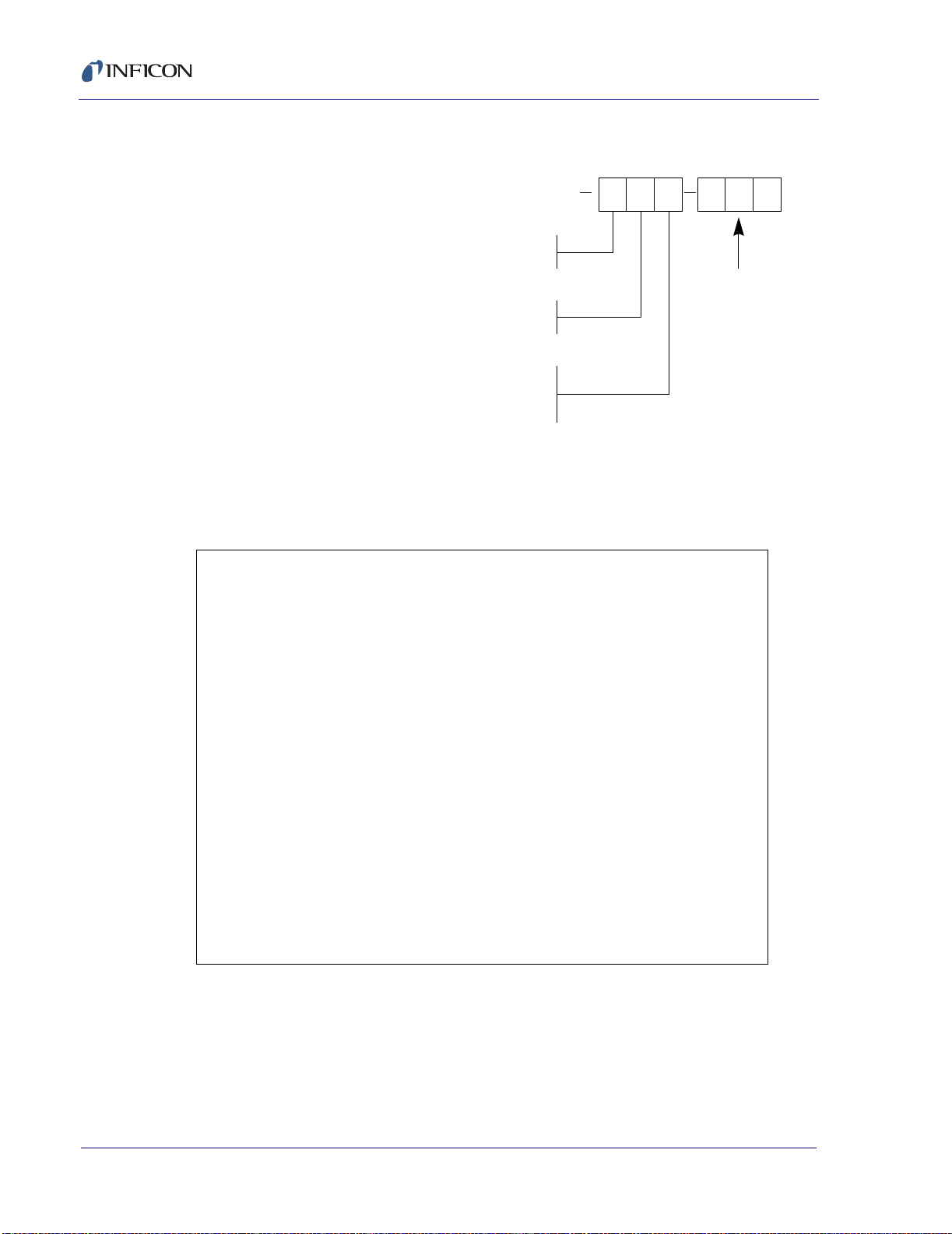
3 Inspect the fuse. See Figure 2 -3.
Figure 2-3 Clip, Fuse Holder, Fuse
Conversion Clip
XTM/2 Operating Manual
Fuse
Holder
Fuse
The Corcom fuse holder has chambers for two 1/4" x 1 1/4" (5 mm x 20 mm)
fuses. Since only one fuse is used, that fuse must be on the live (hot) side and
a conversion clip is inserted to bridge the un used fuse cham ber in the neu tral
side.
An additional function of the conversion clip is to act as a polarization key to
assure that only the neutral line can be bridged leaving the live (hot) line always
fused. A special feature has been built into the live side of the f use holder
compartment of the housing. It will interfere with the conversion clip and
therefore stop the fuse holder from being ins erted fully int o the housing if the
clip is on the live side.
IPN 074-186S
When the power entry module is flipped around for vol tage changing, the
conversion clip must be re-installed to the other side. Otherwise, the fuse holder
will not seat completely into the housing and the power entry module will not
function.
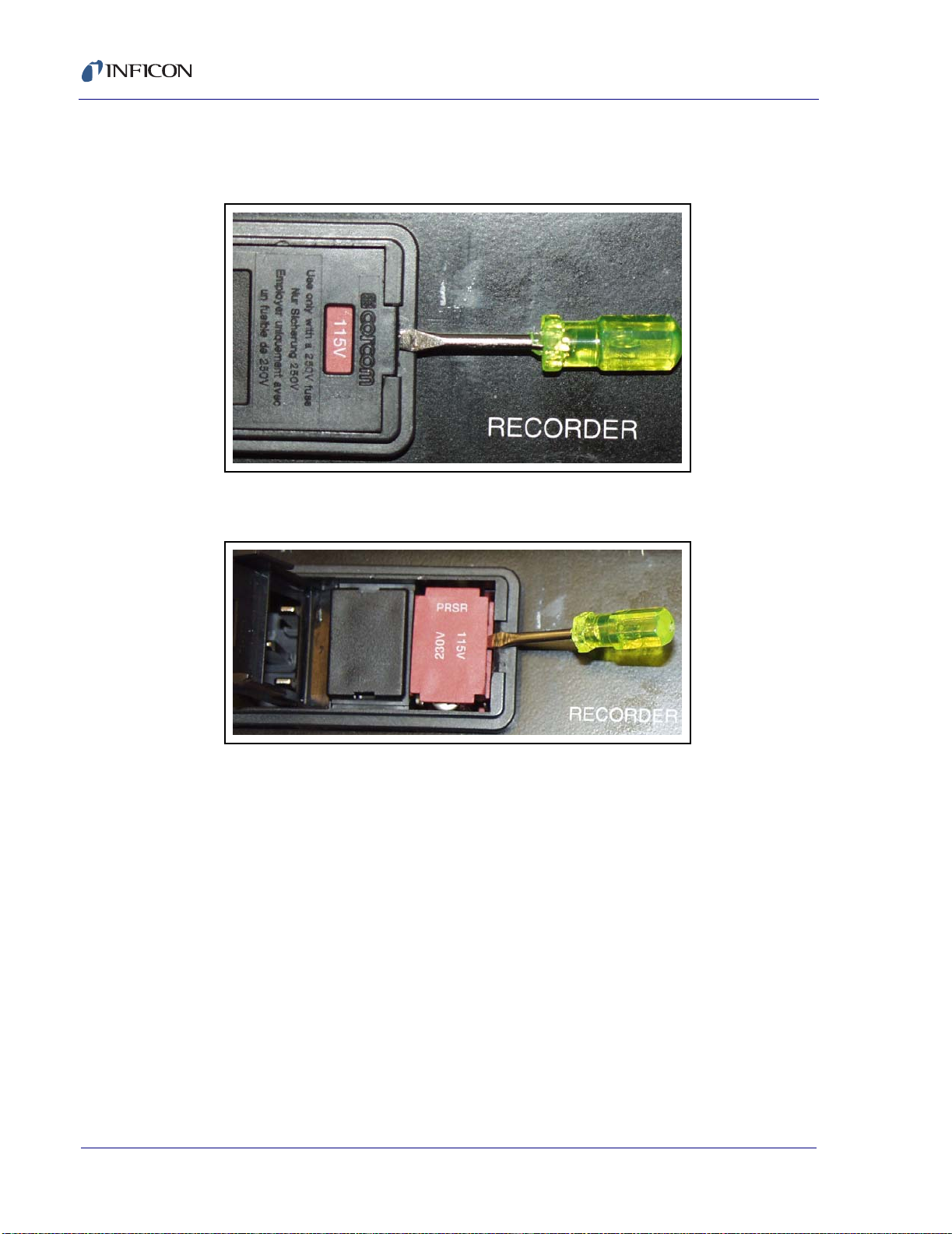
The proper location of the conversion clip is at the left hand side of the voltage
number selected, that is, the upright voltage numb er. See Figure 2-4.
2 - 5
Page 32

XTM/2 Operating Manual
Figure 2-4 Proper Clip and Fuse Location
Once the fuse and clip have been configured, the fuse holder is inserted into
the power entry module housing with the fuse towards the bottom of the
instrument (and the clip toward s the to p) with the des ired voltage showi ng
through the hole into the cover.
2 - 6
IPN 074-186S
Page 33

2.3 Installation Guide and Schematic
Many experienced deposition monitor users will be able to fu lly install and use
the instrument by studying the installation schematic, Figure 2-5 on the next
page, and the State Sequence Diagram, Figure 4-2 on page 4-2.
A more systematic approach would be to start by reviewing the two figures and
then following the procedure below.
WARNING
Completely review section 1.1 on page 1-1 on safety.
All warnings in this section, as well as ones fo und in
other sections listed below, must be followed to ensure
the safety of the personnel operating this equipment.
1 Che ck for correct line vo ltage, section 2.2 on page 2-3.
2 Verify basic unit operation by exercising it in the Test Mode, section 3.6 on
page 3-11.
XTM/2 Operating Manual
3 Review the system interface capability as outlined in section 2. 5 on page
2-13. Be especially attentive of the specia l features availab le on the
configuration switches, section 2.5.2 on page 2-15
4 Wire the necessary connectors following the installation procedures in
section 3.1 on page 3-1, section 3.2 on page 3-1, and section 3.3 on page
3-4.
5 Revi ew the front panel controls and disp lay descript ion per section 2.4 on
page 2-9.
6 Program the desired film parameter values per section 4.1 on page 4-1 and
IPN 074-186S
section 4.2 on page 4-3.
7 Verify the operation of the just programmed film utilizing the Test Mode.
8 Attach the XIU (757-305-G15, G30 , or G100) to an existing tr ansducer or
install a new transducer following the guidelines of section 3.5 on page 3-7
and Figure 3-3 on page 3-8.
9 Exit t he Test Mode and deposit when ready.
2 - 7
Page 34

XTM/2 Operating Manual
Recorder
see 2.5.8
see 3.7.3
IEEE
757-211-G1
REAR PANEL
SensorRS232
see 2.5.5 see 2.5.6
Configuration Switches
see Table 2-1 in section 2.5
System I/O
see 2.5.4 and 3.7
Oscillator Kit
IPN 757-305-Gxx
(Option)
Outputs
Sensor Shutter 1 (Manual)
Sensor Shutter 1
Manual
Source Shutter 1 (N.O. Relay Contact)
Source Shutter 1
From Local Line Power
100 - 120 V(ac) ± 10%
200 - 240 V(ac) ± 10%
50 - 60 Hz
Feedthrough
IPN 750-030-G1
(Option)
Cooling
\Water
Air, 80 PSI, 110 PSI Max.
XIU (Oscillator)
IPN 757-302-G1
Figure 2-5 Installation Guide Schematic
In
Out
Sensor
Standard Sensor With Shutter
IPN 750-211-G2
(Option)
Sensor
Shutter
Source to Sensor
10” (254 mm) Minimum
Shutter
Shutter
Source Controller
Such As Electron
Beam Gun
Power Supply
Pneumatic
Actuator
Solenoid Assy.
24 V(ac) or V(dc)
Power Supply
IPN 007-199
IPN 074-186S
2 - 8
Rotary
Feedthrough
Compressed Air
Actuator
Power Supply
Page 35

2.4 XTM/2 Front Panel Description
Figure 2-6 Front Panel XTM/2
123
XTM/2 Operating Manual
4
13
2.4.1 XTM/2 Front Control Panel Description
1— LCD DISPLAY
Display of current information and parameters. See section 2.4.2 on page
2-11 for details.
2— XTAL
Pressing this key momentarily switches the display to percent of crystal lif e
used, software version, and crystal frequency, when the display is in
operate mode. If the Frequency display mode is chosen (see section 2.5.2
on page 2-15), pressing this key provides temporary added displ ay
resolution to 0.01 Hz.
3— ZERO
Zeros the displayed thickness and elapsed time whe n the dis play i s in th e
operate mode.
5
6
789101112
4— OPEN
Closes the "shutter" relay’s contacts and "zeros" the accumulated
IPN 074-186S
thickness (mass) and elapsed time.
5— CLOSE
Opens the "shutter" relay’s contacts and initiates a data log when the
instrument is properly configured. See section 3.8.4 on page 3-21.
6— PROG
Program. Toggles the display between the program and operat e modes.
7— ON/STBY
Switches secondary power of the instrument between ON and STANDBY.
8—
Green LED illuminates to indicate that the unit is connected to an active line
power source and the ON/STBY switch is set to ON.
2 - 9
Page 36

XTM/2 Operating Manual
9—
Access to adjust LCD contrast, see section 6.1 on page 6-1.
10—
Enter and cursor down. Two function switch used when the display is in the
program mode.
11— DIGITS (0-9)
Decimal based key pad for data entry.
a. If the zero key is held down duri ng power-up, the co mmunication s
interface may be configured (see section 3.8.1 on page 3-16 )
b. If the nine key is held do wn during power-up, al l of the LCD segme nts
will remain lit until the key is released, see Figure 2-7 on page 2-11.
12—
Clear and cursor up. Two function switch that is used when the display is
in the program mode.
13—
Optional mounting kit, (IPN 757-212-G1) for mo unting one unit in f ull rack
or (757-212-G2) for mounting two units side by side in full rack .
2 - 10
IPN 074-186S
Page 37

2.4.2 XTM/2 Display Description
Figure 2-7 XTM/2 Display
12
XTM/2 Operating Manual
11
10
9
8
7
3
4
5
6
1— RATE DISPLAY GROUP
Indicates the deposition or etching rate in the dis played un its, or used to
display the tooling value when the display is in the Pro gram mode. Also
used to briefly display %of Xtal life (based on 5 MHz = 100%) when xtal is
pressed and the display is in the operate mode. Displays the most
significant frequency information in the freque ncy monitor mod e.
2— THICKNESS/MASS GROUP
Indicates the deposited or et ched t hickness (mass) in the displayed units.
Also used for briefly displaying the monitor crystal’s frequency when the
xtal key is pressed in the operate mode. This group is also used for
displaying density (gm/cc) when in the program mode. Displays the least
significant frequency information in the freque ncy monitor mod e.
3— STATUS MESSAGE GROUP
When illuminated, indicates that the shutter is open and if the specified limit
was exceeded.
IPN 074-186S
4— TEST MODE INDICATOR
When illuminated, indicates that the test mode configuration swit ch has
been set.
5— COMPUTER I/O OVERRIDE
Illuminates when control of one or more relays have been reconfigured
through computer communications.
6— ETCH MODE ON INDICATOR
When illuminated, indicates that the etch mode configuration swit ch has
been set. The thickness display now indi cates the am ount remov ed.
7— TIMER GROUP
Elapsed time indicator and unit annunciator. Displays the software version
number when XTAL key is pressed while display is in operate mode.
2 - 11
Page 38

XTM/2 Operating Manual
8— PROGRAM MODE GROUP
Indicator annunciator and cursor array for the defini tion of parameters.
9— FILM GROUP
Indicates which stored film’s parameters are being used in the operate
mode, or being changed/programmed in the program mode. The active film
may be changed when the cursor is blink ing.
10— COMMUNICATIONS ACTIVITY GROUP
Illuminates whenever computer communications are being sent or
received, respectively.
11— CRYSTAL FAIL INDICATOR
Illuminates whenever the ModeLock system cannot drive a crystal, or a
crystal has been shifted by loading beyond 5 MHz. May also illuminate
when there is a cable or sensor failure.
2 - 12
IPN 074-186S
Page 39

2.5 XTM/2 Rear Panel Description
The rear panel provides the interface for all external co nnections to th e
instrument. Each ballooned item is covered in the following respectively
numbered sub-paragraphs.
Figure 2-8 XTM/2 Rear Panel
XTM/2 Operating Manual
1
3
456
2
910
8
7
IPN 074-186S
2 - 13
Page 40

XTM/2 Operating Manual
2.5.1 Power Module
Allows selection of optional voltages, contai ns the instrument fuse and provides
modular connection to line power. Refer to section 2.2 on page 2-3.
Figure 2-9 Power Module
2 - 14
IPN 074-186S
Page 41

2.5.2 Configuration Switches 1 & 2
Two eight position DIP switches used to customize the instrument as follows.
Figure 2-10 Configuration Switch
CAUTION
The configuration switches are only read on
instrument power up. If an option is changed the
instrument must be switched to standby and then
powered up to effect the ch ange.
XTM/2 Operating Manual
IPN 074-186S
2 - 15
Page 42

XTM/2 Operating Manual
Table 2-1 Configuration Switch Settings
Switch 1 Test Mode (0 = off, 1 = on)
Switch 2 Parameter Lock (0 = off, 1 = on)
Switch 3 Beep On/Off (0 = on, 1 = off)
Switch 4 Close Shutter on
(0 = yes, 1 = no)
Crystal Fail
Switch 5 Continue
(0 = off, 1 = on)
Thickness/Timer
Accumulation Option
With Switch 5 in the On position, pressing the OPEN button adds to the
Thickness and Time counters and does not zero previously accumulated
Thickness or Time. Pressing CLOSE freezes the Thickness and Time
displayed at the current value. The displayed Rate will not be frozen. The Zero
function works normally and can be used to zero accumulated Thickness or
Time at any time.
Switch 6 Unused
Switch 7 Unused
Switch 8 Etch Mode (0 = off, 1 = on)
Switch 9 Displayed units MSB 00 = kÅ, 01 = µgm
Switch 10 Displayed units LSB 10 = mgm, 11 = MHz
Note: recorder function remains as Å/sec or Å in the
MHz setting.
Switch 11 Recorder function
MSB
00 = Rate, ±2000Å/sec, 1000ng/sec or 200µgm/sec
01 = Rate, ±200Å/sec, 100ng/sec or 20 µgm/sec
10 = Rate, ±20Å/sec, 10ng/sec or 2 µgm/sec
Switch 12 Recorder function
LSB
Switch 13 Recorder Output &
Display Averaging
MSB
Switch 14 Recorder Output &
Display Averaging
LSB
Switch 15 Unused
Switch 16 Unused (Reserved)
2 - 16
11 = Thickness, Modulus ±2000Å, 2000ng or 2000µgm
00 = 1/4 sec
01 = 1 sec
10 = 4 sec
11 = 16 sec
Note: Display average is always 1 second or greater.
IPN 074-186S
Page 43

2.5.3 Grounding Stud
Recommended point for connecting t he syste m ground s trap. Fo r specifi c
recommendations see section 3.2, Electrical Grounding and Shielding
Requirements, on page 3-1.
Figure 2-11 Grounding Stud
XTM/2 Operating Manual
IPN 074-186S
2 - 17
Page 44

XTM/2 Operating Manual
2.5.4 System I/O
A 25-pin male "D" type connector for interface connecti on. (See sect ion 3. 7 on
page 3-14 for details.) The outputs are normally open type relays.
Figure 2-12 25-Pin Male "D" Connector
14,15,16,17
*The function of the relay outputs may be altered to
be controlled remotely through the computer
communications, see section 3.8.5.6 on page 3-26
for more information on the Remote Command.
Pin # Function*
Outputs
1,2
3,4
5,6
7,8
Source Shutter
Thickness Setpoint
Timer Setpoint
Sensor Fail
Inputs
9
18
19
20
21
Crystal Fail Inhibit
INPUT Common (GND)
OPEN shutter
CLOSE shutter
Zero thickness
Zero timer
2 - 18
IPN 074-186S
Page 45

2.5.5 RS232
XTM/2 Operating Manual
A 9-pin female "D" type connector which enables the instrument to be controlled
by a host computer. See section 3.8 on page 3-16 for details.
Figure 2-13 9-Pin Type "D" Female Connector
IBM Compatible
Host Computer
Pin # Description DB9-Pin DB 25-Pin
1 Not used 1 2 TXD Data transmitted from XTM2 2 3
3 RXD Data received by XTM/2 3 2
4 Not used 4 5 GND Signal ground 5 7
6 DTR Output from XTM/2 indicating ready to transmit 6 6
7 CTS Input to XTM/2 indicating stop transmitting 7 4
8 Not used 8 9 GND Shield ground 9 -
IPN 074-186S
2 - 19
Page 46

XTM/2 Operating Manual
2.5.6 Sensor
High density 15-Pin female "D" type input connect ors for intellige nt oscillators
(IPN757-302-G1). These oscillators are normally supplied with 15’ (4.572 m)
cables as IPN 757-305-G15. These are specifiable as 30’ (9. 144 m) and 100’
(30.28 m) by changing the group (G-xx) de signa tion to 30 or 100, re spect ively.
Figure 2-14 15-Pin Type "D" Female Connector
2.5.7 International Warning Symbol for Users and Technicians
operating and maintenance (servicing) instructions in the lite rature
accompanying the instrument.
2.5.8 Recorder
A BNC type connector that supplies analog voltage proportional to rate or
thickness (mass). The specific function is determined by configuration switches
9-14, refer to section 2.5.2 on page 2-15.
Figure 2-15 BNC Connector
This symbol is intended to alert the user to the presence of important
IPN 074-186S
2 - 20
Page 47

2.5.9 Comm. Option
Location of optional computer interface, see se ction 3.8 on p age 3-16 for setup
details.
Figure 2-16 IEEE-488 Option
2.5.10 Manufacturer’s Identification and Serial Number Plate
This plate is installed at final assembly to identif y the instrument’s model and
serial numbers.
XTM/2 Operating Manual
Figure 2-17 Serial Number Plate
IPN 074-186S
2 - 21
Page 48

XTM/2 Operating Manual
2.6 Operation as a Deposition Monitor
Although this instrument is designed as a vacuum deposition/etch monitor, it is
also easily used for many other types of mass measureme nt applic ation s. It is
easily installed by reviewing section 2.3 on page 2-7 for a schematic view of the
installation requirements and section section 4.1 on pa ge 4-1 for an ov erview
of instrument function.
The following discussion is divided into four seg ments. The first is for
applications that do not require a sourc e shutter. The second relates to those
that use a source shutter. The third section is a simple application of the
instrument for manual rate sampling. The fourth segment is directed towards
those applications that are nontraditional; including biological, electroplating,
etching and the measurement of liquid samples. The units may be programmed
in Å/KÅ or µgm/mgm/ngm depending on the setting of configuration switches 9
and 10, refer to section 2.5.2 on page 2-15. If these switches are subsequently
changed, the two thickness parameter values of the active film are
appropriately recomputed.
2.6.1 Monitoring - Systems Without a Source Shutter
To operate the instrument as a film rate/thickness moni tor only the f ollowing
three parameters need to be programmed. Press the PROG key to switch the
display in the program mode and enter the appropri ate values. The values
entered for these parameters are independent of which units are c hosen for
display (thickness or mass).
DENSITY . . . . . . . . . . . . . . . . . . .Depends on the material to be measured,
see Appendix A, Table of Densities and
Z-ratios.
Z-RATIO . . . . . . . . . . . . . . . . . . . . Depends on the material to be measured,
see Appendix A, Table of Densities and
Z-ratios.
TOOLING . . . . . . . . . . . . . . . . . . .Corrects for the geometrical differences
between the sensor and the substrate, se e
section 5.3 on page 5-2.
Properly mount and attach the ap propriate transducer (see section 3.5 o n page
3-7).
Press the PROG key to change the display between the prog ram and op erate
modes.
IPN 074-186S
2 - 22
The Rate display group will indicate the evaporation rate and the Thickne ss
(mass) display group will increment a cco rdin gly. The front panel controls work
normally.
Page 49

XTM/2 Operating Manual
2.6.2 Monitoring - Systems with a Source Shutter
In addition to measuring rate and thickne ss, th ese instrum ents can be used to
terminate the deposition at the proper thickn ess. I mplem entation requ ires that
the deposition system have a source (or substrate) shutter capable of automatic
operation. The source shutter controller must be wired through the SYSTEM I/O
connector on the rear panel of the instrument. The following parameters (in
addition to those required in section 2.6. 1 on page 2-22) must also be
programmed.
FINAL THICKNESS . . . . . . . . . . . Program to the desired film th ickness (or
mass).
The operator manually increases the s ource power (using the s ource power
supply’s control) to the nominal operating level. O nce the u ser i s s atisf ie d, t he
deposition begins when the OPEN switch is pressed. This action zeros the
accumulated thickness display and opens the source shutter. The operator
must then adjust the source power manually to ach ieve the desired rate . The
shutter will close automatically when the final thickness set point is achieved.
2.6.3 Rate Sampling
It is possible to use these instruments to periodically sa mple the rate i n a
deposition system. A shuttered transducer must be used, see section 3.4 on
page 3-6.
NOTE: It will be useful to refer to the separate INFICON Crystal Sensor Manual
(see list below) for transducer and actuator control valve installation.
IPN Type
074-154 . . . . . . Bakeable
074-155 . . . . . . CrystalSix
074-156 . . . . . . Standard, Compact and Dual
074-157 . . . . . . Sputtering
1 Elec trically connec t the pneumatic shutter actuator con trol valve (IPN
007-199) to the sensor shutter pins (1, 2) of the SYSTEM I/O connector.
IPN 074-186S
2 Program the FINAL THICKNESS parameter to a value which allows
approximately 20 seconds of material accum ulation onto the se nsor head.
For example, if the nominal rate is 20 Å/sec, set the final thickness to 20 sec
x 20 Å/sec = 400Å. If the sample time is too short there could be errors
induced by temperature transients across the monitor crystal.
A sample is initiated by pressing OPEN. This zeros the displayed thickness and
opens the sensor shutter. The operator may view the deposition rate display
(allowing it to stabilize) and then comparing it to the desired rate. If a time longer
than the programmed sample time is required to adjust the ac tual depositio n
rate the operator can increase the FINAL THICKNESS value.
NOTE: This arrangement does not allow automatic substrate final thickness
termination.
2 - 23
Page 50

XTM/2 Operating Manual
2.7 Nontraditional Applications
In addition to their normal application as a deposition monitor/controller, quartz
crystal microbalances have significant utility as generalized mass sensors. This
particular instrument family is capable of measuring mass increases or
decreases on the face of the monitor crystal to an accuracy of +/- 1.23
nanograms/cm
always, it is imperative that the mass be well adhered to the face of the crystal
or improper readings will be taken. It is especially important to recognize this
requirement for measurements of liquids or other non-rigid materials.
INFICON’s 6MHz crystal holders have an open area of ~0.535 cm
highest accuracy possible, it is suggested tha t the individu al crystal holder be
measured with a traveling microscope to determine the ex act opening area.
2.7.1 Etching
The instrument may be configured to display the thick ness or mass removed
from the face of a crystal. It is imperative that the material be remo ved uniformly
over the active area of the crystal or improper readings will be taken. This
inaccuracy occurs because of radial mass sensitivity differences across the
face of the monitor crystal.
2
in a single 250 ms measurement (density = 1.00, z = 1.00). As
2
. For the
The etch mode is established by setting a configuration switch (refer to section
2.5.2 on page 2-15) on the back of the instrument.
The unit is operated normally, with the ZERO or START keys used to zero the
displayed thickness. The FINAL THICKNESS parameter may be programmed
to terminate the process.
2.7.2 Immersion in Liquids
Measurement of mass change in liquids is a relatively new field, consequently
application information is limited. The energy loss from the vib rating crystal into
the liquid environment is high, limiting the accuracy of the measurement in
some cases. The ModeLock oscillator again provide s superior performa nce,
allowing operation in liquids of higher viscosity than an active oscillator system
would provide. The presence of bubbles on the face of the crystal as it is
immersed will drastically change the noted frequen cy shift and alter the
sensitivity of the technique from immersion to imme rsion. Special transducers
may be required as many liquids can electrically short the crystal’s drive voltage
and induce a crystal failure.
NOTE: It is not recommended to use standard INFICON transducers in liquids
without modification.
IPN 074-186S
2 - 24
Page 51

2.7.3 Biological
The measurement of biological specimens is subje ct to many of the same
problems as covered in the measurement of liquids.
2.7.4 Measurement of Liquids
The measurement of the mass of a liqu id on the face of a cryst al is a techniq ue
that is subject to very large errors. The two primary problems with liquids are
that they are not infinitely rigid structures and do not necessarily form in uniform
layers. Because liquids do not oscillate as a rigid solid , not all of the mass
participates in the resonance . Conseq uent ly, not all of the liquid is detected. In
some ways, the crystal is more appropriately called a viscosity sensor. The
second problem is that liquids tend to form spheres on the face of the crystal
after only very modest accumulations of a few monolayers. This aggravates the
problem caused by non-infinite rigidity. Another aspect of the problem is that the
liquid spheres form at random locations across the crystal. Because monitor
crystals have differential radial mass sensitivity an uncontrollable measurement
problem exists. Spheres formed at the center of the crystal contribute more than
spheres formed near the edge of the sensor’s aperture.
XTM/2 Operating Manual
2.7.5 Use as a Frequency Counter
The ability to measure a c rystal’s frequency betwe en 6.0 00000 an d 5.00 0000
MHz may be accessed by setting the "displayed units" configuration switches 9
and 10 (refer to section 2.5.2 on page 2-15). The displayed frequency is
averaged according to the sett ing of t he record er and d isplay a veraging
configuration switches. In addit ion, by pressing the LIFE key, even finer
frequency resolution is displayed (x.xx or x.x Hz), suppressing the most
significant data. Data to 0.1 Hz is always available through the computer
interface for the latest 0.25 sec. measurement.
The recorder output and programmed limits of this instrument behave as if the
"displayed units" configuration switches were set to 00 or "kÅ".
IPN 074-186S
2 - 25
Page 52

XTM/2 Operating Manual
2.7.6 Contamination Detection
The measurement of a crystal’s mass loss or gain is enhanced by utilizing the
averaging and displayed units configuration switches, refer to section 2.5.2 on
page 2-15. These may be used to directly display the mass change in
micrograms (µgm) or milligrams (mg). In addition, the displayed re solution may
be enhanced by increasing t he mea surement time av eraging t o as l ong as 16
seconds. This technique reduces the relative noise in the ratio of the square
root of the sample time.
The limiting problem will most probably be either te mperature chang es of the
monitor crystal or the instrument’s reference crystal. Careful temperature
control can minimize these effects.
2 - 26
IPN 074-186S
Page 53

3.1 Installing the Instrument - Details
A general schematic of instrument installation i s given in sectio n 2.3 on page
2-7, use it for reference. The importance of grounding the instrument cannot be
over emphasized for both safety and pe rformance needs.
3.1.1 Control Unit Installation
Review the specific suggestions and warnings concerning safety and
installation that are presented in section 1.1 on page 1-1.
It is generally advisable to centrally locate the controller, minimizing the length
of external cabling. The cable from the instrument to the XIU is 15’ (4.572 m).
Longer cables are specifiable as 30’ (9.144 m) or 100’ (30.28 m), refer to
section 2.5.6 on page 2-20 for ordering details.
XTM/2 Operating Manual
Chapter 3
Installation
The monitor unit is designed to be rack mounted. It may be also used on a table;
four self-adhesive rubber feet are included in the ship kit for this purpose.
3.2 Electrical Grounding and Shielding
Requirements
Careful consideration of simple electrical guid elines during installation will
avoid many problems caused by electrical noise.
To maintain the required shielding and internal grounding as well as insuring
safe and proper operation, the instrument must be operated with all enclosure
covers and option panels in place. These must be fully secured with the screws
IPN 074-186S
and fasteners provided.
3 - 1
Page 54

XTM/2 Operating Manual
3.2.1 Verifying / Establishing Earth Ground
If local facilities engineering cannot provid e a low impedance earth ground
close to the instrument, the following procedure is recommended.
Where soil conditions allow, drive two ten foot copper clad steel rods into the
ground six feet apart. Pour a copper sulfate or other salt solution arou nd the
rods to improve the soil’s conduction. A near zero resistance measurement
between the two rods indicat es tha t a desi rable e arth ground has been
established. In severe cases it may take several soakings of solution over
several days to reach this condition.
NOTE: Keep co nnections to this gro unding network as short as possible. Most
noise transients contain significant power at high frequencies. A long
path adds to the ground circuit's inductance and thereby increases its
impedance at these frequencies.
3.2.2 Connections to Earth Ground
The ground connection on the instrument is a threa ded stud with a hex nut. It
is convenient to connect a ring terminal to t he ground strap, thu s allowing a
good connection with easy removal and installati on. See Figure 3-1 for the
suggested grounding scheme. In many cases, a brai ded ground strap is
sufficient. However, there are cases when a solid copper strap (0.030" (0.762
mm) thick X 1" (25.4 mm) wide) is more suitable because of its lower RF
impedance.
Figure 3-1 System Grounding Diagram
%DFN3DQHO
7UDQVGXFHU
)HHGWKURXJK
*URXQG
6WXG
(DUWK
*URXQG
IPN 074-186S
9DFXXP6\VWHP
3 - 2
Page 55

XTM/2 Operating Manual
CAUTION
An external ground connection is required to ensure
proper operation, especially in e lectrically nois y
environments.
When used with RF powered sputtering systems, the grounding scheme may
have to be modified to optimize the specific situation. An informative article on
the subject of "Grounding and RFI Prevention" was published by H.D. Alcaide,
in "Solid State Technology", p 117 (April, 1982).
3.2.3 Minimizing Noise Pickup from External Cabling
When an instrument is fully integrated into a deposition system, there are many
wire connections; each a potential path for noise to be conducted to the inside.
The likelihood of these wires causing a problem can be g reatly diminish ed by
using the following guidelines:
Use shielded coax cable or twisted pairs for all connections.
Minimize cable lengths by centralizing the controller.
Avoid routing cables near areas that have the potential to generate high
levels of electrical interference. For example, large power supplies, such as
those used for electron beam guns or sputtering sources, can be a source
of large and rapidly changing electro-magnetic fields. Placing cables as little
as 1 foot (305 mm) from these problem areas can be a very significant
improvement.
Be sure that a good ground system and straps are in place as
recommended above.
Ensure that all instrument covers and option panels are in place and tightly
secured with the provided fasteners.
IPN 074-186S
3 - 3
Page 56

XTM/2 Operating Manual
3.3 Connection to Rear Panel
The long term performance of this instrumentation is dep endent o n the qu ality
of the installation. A first rate installation includes the proper assembly of the
user/OEM installed cabling. The assembly instructions for the connectors used
on this instrumentation are shown in the following sections.
3.3.1 The BNC Connectors
Because complete BNC cables are so common, there are no mating connectors
supplied in the ship kit for the source and recorder outputs. It is recommended
that completed BNC type cables be purchased locally, even if one end is cut off
for connection to the external apparatus.
3.3.2 The "D" Shell Connectors
The "D" shell connectors use solder cup contacts that will accept solid or
stranded wire with a maximum individual wire size of 20 AWG. Multiple stranded
wire jumpers may equal 18 AWG, or two 22 AWG wires may be employed. The
recommended wire strip length is 1/4" (6.4 mm).
The duplex tin/lead solder cup readily accepts tinned leads and will securely
strain-relieve wires when properly soldered. Se e Figure 3 -2 on page 3-5 .
The American National Standards Institute Standards For Soldering Electronic
Interconnections (ANSI/IPC-S-815A) is recommended for establishing
soldering quality guidelines.
The soldering procedure is as follows:
1 Obtain a connec tor and wire(s) of the ty pe and size required fo r your
application.
2 Ensure that surfaces to be soldered are clean and free of any contaminants
that may inhibit solderability.
3 Strip wire(s) to recommended st rip le ngth of 1/ 4" (6.4 mm ). Tin the leads if
required.
4 Obtain resin flux , 40/60 alloy solder, and a low-wattage soldering iron.
NOTE: It is common to use heat shrink tubing over solder joints to insulate the
exposed solder connection at the cup. If us ing heat shri nk tubing,
ensure that the tubing sections are cut to proper length and placed on
the wire(s) prior to soldering. After wires are terminated, slide tubing
over solder connections and shrink with an appropriat e heat source.
IPN 074-186S
3 - 4
Page 57

XTM/2 Operating Manual
5 Coat the stripped portion of the wire(s) with the flux and insert into the solder
cup of the contact until the conductor is bottomed in the cavity.
6 Heat the solder cup with the soldering iron and allow the solder to flow into
the cup until the cavity is filled but not over filled.
7 Continue soldering wires until all terminations are complete.
8 Cle an the so ldered conn ections with a suitable alcohol/ water rinse to
remove flux and solder residue.
Figure 3-2 Solder Cup Connector
Wire Strip
Length 1/4" (6.4 mm)
Solder Cup
Contacts
Grounding
Indents
(Plug Only)
IPN 074-186S
3 - 5
Page 58

XTM/2 Operating Manual
3.4 Sensor Selection Guide
The choice of sensor type must be dictated by the process, the deposition
material and the physical characteristics of the process chamb er. General
guidelines for each sensor type produced by INFICON are ou tlined in the
Sensor Selection table below. For specific recommendations, consult your
INFICON representative.
Table 3-1 Sensor Selection Table
Temp
Name IPN
Standard 750-211-G1 130° Front Side
Standard
w/Shutter
Compact 750-2 13-G1 130° Front Rear For tight spaces
Compact
W/Shutter
Dual 750-212-G2 130° Front Side Two crystals for
Sputtering 007-031 130° Rear Side For RF and diode
Bakeable
12" (304.8 mm)
20" (508 mm)
30" (762 mm)
Bakeable
w/Shutter
12" (304.8 mm)
20" (508 mm)
30" (762 mm)
CrystalSix 750-446-G1 130° Front Side 6 crystals for process
*These temperatures are conservative maximum device temperatures, l imited by the properties
of Teflon at higher temperatures. In usage, the water co oling allows operation in envi ronments
that are significantly elevated, without deleterious effects.
750-211-G2 130° Front Side
750-213-G2 130° Front Rear For tight spaces
007-219
007-220
007-221
750-012-G1
750-012-G2
750-012-G3
°C
450° Front Side Must remove water
450° Front Side Must remove water
Crystal
Exchange
Utility
Connector Comments
crystal switch.
Includes Shutter
sputtering. (Optional
shutter available.)
cooling and open the
tubes prior to bakeout
cooling and open the
tubes prior to bakeout
security.
IPN 074-186S
3 - 6
NOTE: Do not allow water tubes to freeze. This may happen if the tubes pass
through a cryogenic shroud and t he wa ter flow is interru pted.
NOTE: For best operation, limit the maximum input water temperature to less
than 30 °C.
NOTE: In high temperature e nvironmen ts more heat may transfer to the water
through the water tubes than through the actual transducer. In extreme
cases it may be advantageous to use a radiation shield over the water
tubes.
Page 59

XTM/2 Operating Manual
3.5 Guidelines for Transducer Installation
WARNING
The performance of this instrument depends on the
careful installation of the chosen transducer. Improper
installation will cause problems with depo sition
repeatability, crystal life and rate stability.
3.5.1 Sensor Installation
Figure 3-3 shows a typical installation of an INFICON water cooled crystal
sensor in the vacuum process chamber. Use the illustration and the following
guidelines to install your sensors for optimum performance an d convenienc e.
IPN 074-186S
3 - 7
Page 60

XTM/2 Operating Manual
Figure 3-3 Typical Installation
Sensor
Shutter
Source to Sensor
10" Minimum
Mounting Bracket
Coax Cable
(Routed with
Water Tubes)
Brazing
Adapters
Or,
Customer Supplied
Cajon Coupling
Source
Shutter
Source
Pneumatic
Actuator
To Pins 1, 2
or System I/O
Manual
Control
To
Source Controller
IPN 007-199
Shutter
Solenoid
Assembly
Out
Water In
Water Out
XIU (Oscillator)
In
IPN 757-302-G1
Air, 80 PSI, 110 PSI Max.
Manual
Switching
IPN 074-186S
3 - 8
Page 61

XTM/2 Operating Manual
SENSORS
Generally, install the sensor as far as possi ble from the e vaporation s ource (a
minimum of 10" or 254 mm) while still being in a position to accumulate
thickness at a rate proportional to accumulati on on the substr ate. Figure 3-4
shows proper and improper methods of installing sensors.
To guard against spattering, use a source shutter or crystal shutter to shield the
sensor during the initial soak periods. If th e crystal is hit with even a min ute
particle of molten material, it may be damaged and stop oscillat ing. Even in
cases when it does not completely stop oscillating, it may become unstable.
Figure 3-4 Sensor Installation Guidelines
CO RRECT
INCO RRECT
OBSTRUCTION
INCO RRECT
INCO RRECT
SO URCE
IPN 074-186S
CO RRECT
3 - 9
Page 62

XTM/2 Operating Manual
3.5.2 CrystalSix
Installing the CrystalSix transducer requires that the crystals be manually
advanced. Follow the guidelines in the CrystalSix Opera ting Manual (IPN
074-155) and Figure 3-5.
Figure 3-5 CrystalSix Installation for XTM/2
3 - 10
IPN 074-186S
Page 63

3.5.3 Check List for Transducer Installation
c
Mount the sensor to something rigid and fixed in th e chamber. Do not rely
on the water tubes to provide support.
Plan the installation to insure that there are no obstructions blocking the
path between the Sensor and the Source. Be certain to consider rotating or
moving fixtures.
Install sensors so their central axis (an imaginary line d rawn normal to the
center of the crystal’s face) is aimed directly at the virtual source being
monitored.
Be sure there is easy access for the exchange of crystals.
For systems employing simultaneous source evaporation (co-dep), try to
locate the sensors so the evaporant from each source is only flowing to one
sensor. This is not generally possible to do without special shielding or
optional "material directors" for the transdu cers.
The use of water cooling is always recom mended, even a t very lo w heat
loads and low rates.
XTM/2 Operating Manual
If penetrating a cryogenic shroud, be sure that the coolin g water is kept
flowing or drained between uses. Failure to do so could cause the water to
freeze and the water tubing to rupture.
Avoid running cold water tubes where condensation can drip into the
feedthroughs. This condensate can effectively short the crystal drive
voltage, causing premature crystal failure.
3.6 Use of the Test Mode
This instrument contains a software controlled test mode which simulates
actual operation. The purpose of th e Test Mode is to verify basic operation and
for demonstrating typical operation to the tec hnician.
IPN 074-186S
The Rate displayed during Test Mode operation is determined as follows:
isplayed Rate
All relays and inputs operate normally during Test Mode operation.
------------------------------------------------- -
=
DENSITY (gm/cc)
40
·
TOOLING (%)
----------------------------------------
×
100%
Å/se
[1]
3 - 11
Page 64

XTM/2 Operating Manual
3.6.1 Operational Test
The power switch should be in the STBY position before the instrument is
connected to line power.
Perform the self test as follows:
1 Verify that no system cables other than the power cord are connected to the
unit. Relays may be verified with an ohm meter or custom test box.
2 Set conf iguration switch 1 to the "ON" posit ion.
3 Press the ON/STBY swit ch, the green power LED should illuminate. If Err
is displayed on the LCD, see section 6.2 on page 6-1.
4 Th e following LCD displa ys will appear:
TEST
XX:XX PHASE MIN:SEC
XTAL FAIL
5 Press the PROG key. The program display will appear and the cursor will
be located beside DENSITY.
6 Refer to the list of parameters in Table 3-2 and enter the data
as they are given.
Table 3-2 Operational Test Parameters
DENSITY 02.73 gm/cc
Z-RATIO 1.000
TOOLING 110 %
FINAL THICKNESS 2.000 KÅ
SPT THICKNESS 1.000 KÅ
SPT TIMER 1:00 min:sec
NOTE: There is a built-in "TEST FILM" with all of the parameters
preprogrammed, as shown in Table 3-2. It is accessed by moving
the cursor to the FILM parameter and en tering zero. T he two
thickness values will be modified if the mgm or µgm display mode
has been selected. Press the PROG key to exit the display mode
and continue with step 9.
7 Wh en the correct sequ ence of numerals ap pear in the flashin g display,
press the key to enter and store the data.
8 Press the PROG key to exit the progra m display.
IPN 074-186S
3 - 12
9 Press OPEN to begin the programmed sequence.
10 Th e SHUTTER OPEN annunciator is displ ayed.
Page 65

XTM/2 Operating Manual
11 The time begins to increment from 00:00 and the deposition rate will be 16.1
Å/s. The THICK SPT annunciator is lit at 1.000 kÅ and the TIMER SPT lights
at 1:00 min:sec. Reaching the FINAL THICKNESS parameter of 2.000 kÅ
takes and elapsed time of 02:05, then after reaching FINAL THICKNESS
limit the SHUTTER OPEN annunciator disappears. The clock immediately
begins counting up from 00:00 again.
12 The instrument will remain in this mode until OPEN is pressed.
13 Wh en OPEN is pressed, the process will repeat steps 11 through 13.
14 After successful completion of the above steps, power down the instrumen t
to leave the TEST mode by turning configuration switch 1 "OFF" and then
placing the unit first in STBY and then "ON" to read the new configuration.
IPN 074-186S
3 - 13
Page 66

XTM/2 Operating Manual
3.7 Input and Output Details
3.7.1 Relays
WARNING
The relay, relay circuit, and assoc iated pins in the I/O
connector(s) have a maximum voltage rating of
30 V(dc) or 30 V(ac) RMS or 42 V(peak ). T he max imum
current rating per connector pin or relay contact is
2.5 Amps.
Their function is as follows:
Table 3-3 System I/O Connector
Pin # Function* Closed Contacts Open Contacts Relay #
1,2 Source Shutter During "Shutter Open"
3,4 Thickness
Setpoint
5,6 Timer Setpoint When SPT TIMER is
7,8 Crystal Fail When crystal fails to
Function may be overwritten by Remote Communications Commands "R6 - R9", see
section 3.8.5 on page 3-22.
State.
When SPT
THICKNESS is
exceeded.
exceeded.
oscillate.
Balance 1
Balance 2
Balance 3
Balance 4
3 - 14
IPN 074-186S
Page 67

3.7.2 Inputs
XTM/2 Operating Manual
Inputs are activated by pulling the specific input's t erminal to ground (<0.8V)
through a contact closure to common (GND) or with TTL/CMOS logic having
current sink capability of 2 ma (1 low power TTL load). These ports are read
every 250 ms; signals must be present during a read cycle.
Table 3-4 System I/O Connecto r
Pin # Function Description Input #
14,15,16,17 Input Common (GND) Used as reference for activating
any of the inputs
18 OPEN Detection of a falling edge
duplicates front panel OPEN
19 CLOSE Detection of a falling edge
duplicates front panel CLOSE
9 CRYSTAL FAIL
INHIBIT
20 ZERO thickness Detection of a falling edge
21 ZERO timer Detection of a falling edge
Presence of a closure to ground
reference prohibits the closure
of the Crystal Fail Relay.
duplicates the front panel
ZERO, for thickness only.
duplicates the front panel ZERO
for the timer only.
1
2
3
4
5
3.7.3 Chart Recorder
The chart recorder output has 12 bit resolution with one additional bit of sign
information over the range of -10 to +10 volts. It can supply up to 5 milliamps
and has an internal resistance of 100 ohms. The outp ut is proporti on al to ra te ,
thickness or rate deviation depending on the setting of the configuration
switches; see section 2.5.2 on page 2-15. It is normal for ripple to appear on
IPN 074-186S
these outputs to a maximum of 5 mV at ~84 Hz. This output is updated every
250 milliseconds.
3 - 15
Page 68

XTM/2 Operating Manual
3.8 Computer Communications
This instrument supports a number of standard and optional comp uter
communications protocol formats. RS232 is standard, operating in either
INFICON checksum or non-checksum as well as SECS II formats. The unit may
also be configured to automatically output process data (data logging) upon
reaching FINAL THICKNESS. Pressing the shutter CLOSE switch on the front
panel will also initiate a data dump.
3.8.1 Communications Setup
The XTM/2 has serial communications as a standard feature. Rates from 1200
to 9600 baud are accommodated. Refer to section 2.5.5 on page 2-19 for
RS232 connector details.
To configure the remote communication in terface, hold d own the 0 key during
power up. The following set of parameters can then be entered using the digits,
enter, and clear keys.
tyPE (0 = INFICON Checksum, 1 = INFICON no checksum, 2 = SECS, 3 = Data log)
(If SECS is chosen for tyPE the next 5 parameters are accessed):
d ID (Device ID 0-32767)
t1 (Timer 1 per SECS definition) (0-10.0 seconds)
t2 (Timer 2 per SECS definition) (0.2-25.0 seconds in 0.2 increments)
rtrY (Retry limit per SECS definition) (0-31)
dUPL (Duplicate block per SECS definition)
baUd (0=1200, 1=2400, 2=4800, 3=9600)
IEEE (IEEE address, 0-30) - requires optional hardware
When this list is complete, the RECEIVE message is flashed and the choice will
be given to either repeat the list or continue with normal operation. Pressing
ENTER will continue with normal operation. Pressing CLEAR will repeat the list.
IPN 074-186S
3 - 16
NOTE: Do not turn the unit off while in the Communications Program Mode,
otherwise the new parameter values will not be saved properly.
Page 69

XTM/2 Operating Manual
3.8.1.1 IEEE Settings for a National Instruments IEEE-GPIB Board
When establishing IEEE communications the following settings are found to
work using a National Instruments IEEE-GPIB board. These values are set
using the IBCONF.EXE file provided by National Instruments.
Figure 3-6 Board Characteristics
Figure 3-7 Device Characteristics
IPN 074-186S
3 - 17
Page 70

XTM/2 Operating Manual
3.8.2 Basic Command Structure
The following commands are available v ia the computer communications:
E . . . . . . Echo. Returns the sent message.
H . . . . . . Hello. Returns the model and software version number.
Q . . . . . . Query. Interrogates the programmable parameters and returns the
value of parameter requested.
U . . . . . . Update. Replaces the particular parameter with the value sent.
S . . . . . . Status. Sends back pertinent information based on the spe cific
request made.
R . . . . . . Remote. Perform an action based on the s pecific command given.
Many of these mimic front panel keystrokes.
The send and receive protocol formats are described below and use the
following abbreviations:
STX . . . . Start of transmission character
00,NN . . The size of the command is 2 bytes long wi th 00 representi ng the
high order Byte and NN representing the low order byte.
ACK. . . . Command acknowledged character
NAK. . . . Command no t acknowledge d character
LF . . . . . Line Feed (EOT byte for IEEE)
CS . . . . . Checksum
CR. . . . . Carriage Return
CHECKSUM FORMAT (Message Protocol)
To XTM/2: STX 00 NN message_string CS
From XTM/2: STX 00 NN ACK messag e_string CS (if success)
- or STX 00 NN NAK error_code CS (if failure)
NONCHECKSUM FORMAT (Message Protocol) (RS232)
To XTM/2: me ssage_stri ng ACK
From XTM/2: me ssage_string ACK (if success)
IPN 074-186S
3 - 18
- or error_code NAK (if failure)
Page 71

XTM/2 Operating Manual
IEEE488 FORMAT (Message Protocol)
To XTM/2: message_string LF d10 (CHR$10)
From XTM/2: message_string LF (if success)
- or error_code LF (if failure)
SECS FORMAT (Message Protocol)
To XTM/2: NN SECS_10_BYTE_HEADER message CS CS
From XTM/2: NN SECS_10_BYTE_HEADER ACK message CS CS
(if success)
- or NN SECS_10_BYTE_HEADER NAK error_code CS CS
(if not)
If there is a problem, the unit will return a NAK preceded by one of the following
Error Codes:
A. . . . . . . Illegal command
B. . . . . . . Illegal Value
C . . . . . . Illegal ID
D . . . . . . Illegal command format
E . . . . . . . N o data to retrieve
F. . . . . . . Can not change value now
G . . . . . . Bad checksum
NOTE: When transmitting commands directly by typing on a k eyboard , the
entire command, including the "ACK", must b e entere d quick ly.
Otherwise, the instrument will fail to recognize th e transmission as a
IPN 074-186S
valid command.
3 - 19
Page 72

XTM/2 Operating Manual
3.8.3 Service Requests and Message Available
In the IEEE mode there are a number of events which will trigger service
requests, a request by the instrument to transmit information to the host. The
instrument does this by triggering t he RQS bit of the Status Byte. A host initiated
serial poll then identifies the requestin g device by the presenc e of a 1 in the
RQS (2
is encoded in bits 2
6
) bit of the status byte. The particular service request generator even t
0
- 23 inclusive, as shown below:
RQS MAV
7
2
2625242322212
not
used
Table 3-5 Service Request Encoding
Generator Event Code Value
FINAL THICKNESS 0001 1
STBY/ON sequence 0100 4
Crystal Fail 0110 6
250ms DATA READY. Available only
after R23 is issued, see page 3-26.
This is automatically cleared on
crystal failure.
TIMER SPT exceeded 1000 8
THICKNESS SPT exceeded 1001 9
not
used
Service request
generation encoding
0
0111 7
Result of Serial Poll
It takes the instrument various lengths of time to formula te a correct resp onse
to queries for information. To avoid unnecessarily repeated bus traffic, it is
suggested that the host monitor the MAV (message available) status bit to
determine when a response for informati on is fully as sembled and read y to
transmit.
IPN 074-186S
3 - 20
Page 73

3.8.4 Datalogging
Data logging may be configured to be automatic, see section 3.8.1 on page
3-16. The RS232 port is then configured to output the DATALOG information
only and cannot receive commands from a host comp uter. The IEEE option, if
installed, will continue to work in the normal fashion.
The Datalog data output represents the information concerning the latest
SHUTTER OPEN to SHUTTER CLOSE sequence. The data is a series of ASCII
strings, each separated by a carriage return (CR) and line feed (LF), in the order
below:
1Film #
2 Rate = _ _ _.__Å/s [or ngm/sec or µgm/sec] [Last good rate if crystal failed]
3 Thickness = _ _ _ _._ _ _ _ kÅ [or µgm or mgm] [Last good thickness if crystal failed]
4 Deposit Time = _ _:_ _ Min:Sec.
5 Begin Frequency = _ _ _ _ _ _ ._ Hz
6 End Frequency = _ _ _ _ _ _ ._ Hz [negative of last good frequency if crystal fail]
7 Crystal Life = _ _%
XTM/2 Operating Manual
In addition to automatic dataloggin g, the da t alog info rmatio n string is ava ilable
via execution of the S12 communications command, or may be manually
initiated by pressing the CLOSE (shutter) key on the front panel.
IPN 074-186S
3 - 21
Page 74

XTM/2 Operating Manual
3.8.5 Computer Command Details
3.8.5.1 Echo Command
Echoes the message, i.e., returns the sent message.
The format is: E message strin g
3.8.5.2 Hello Command
The HELLO command will return the string "XTM/2 VERSION x.xx" where x.xx
is the software revision code.
The format is: H
3.8.5.3 Query Command
The Query command returns information concernin g current instru ment
parameter values.
The format of the query command is:
QPF - Query parameter P of film F. A space is used as a delimiter between P
and F, where F is a digit between 1 and 9, inclusive,
or
Q 6 - Query the current film number.
Table 3-6 Parameter Definition Table (for Query and Update Commands)
PP XTC/2 Parameter Range
0 Tooling 10 to 500.9 (%)
1 Final Thickness 0 to 999.9999 (kÅ/µgm/mgm)
2 SPT Thickness 0 to 999.9999 (kÅ/µgm/mgm)
3 Density 0.5 to 99.999 (gm/cc)
4 Z-ratio 0.1 to 9.999
5 SPT Time 00:00 to 99:59 (min:sec)
6 Film Number 1-9
99 All See note below
Note: Q 99 F returns parameters 0 to 5 for film F in the
order and ranges as specified above; each parameter is
separated by a space.
IPN 074-186S
3 - 22
Page 75

3.8.5.4 Update Command
The format of the update command is:
U P F vvv.
Update parameter P of film F, with value vvv. A space is used as a delimiter
between the P and F values as well as the F and vvv values, where F is a digit
between 1 and 9;inclusive. Refer to Table 4-2 on page 4-4 for a numbered list
of parameters and their limits.
or
U 6 F
Set the current film number to film F
See Query Command Parameter Definition Table for numbered list of
parameters.
NOTE: The command "U 99 F Tooling Final Thickness SPT Thickness Density
Z-ratio SPT Time" will update all parameters for film F. All parameter
values must be separated by spaces and must use allowed values per
those shown in the Parameter Definition Table.
XTM/2 Operating Manual
3.8.5.5 Status Command
Sends back information based on specific request made.
The format of the status command is:
S xx . . . . Return the status (value) of xx
where:
S. . . . . . . Is the literal S
xx . . . . . . One or tw o digit code pe r list below:
S 0 . . . . . Rat e, Thickness , Time, Xtal-Life
IPN 074-186S
S 1 . . . . . Rate
S 2 . . . . . Thickness
S 3 . . . . . Time
S 4 . . . . . Film
S 5 . . . . . C rystal life (% )
3 - 23
Page 76

XTM/2 Operating Manual
S 6 . . . . . Output status - returns 8 ASCII bytes each with a value of 0 or 1.
S6 Response String
Output # Function
1 Source Shutter
2Thick SPT
3Timer SPT
4 Sensor Fail
Byte 87654321
not used 1 = closed contacts
S 7 . . . . . Input status - returns 8 ASCII bytes each with a value of 0 or 1.
S7 Response Strings
Input # Function
1 Open Shutter
2 Close Shutter
3 Zero Thickness
4Zero Timer
5 Crystal Fail Inhibit
Byte 87654321
S 8. . . . . Present frequency of Crystal
Sxxxxxx.xD
where
x is any digit 0 to 9
S character is a space when good readings are available or a
negative sign for failed crystals
D character is:
0 when there is 0.25 second averaging
0 or 5 when there is 1 second averaging
Even Digit when there is 4 second averaging
x when there is 16 second averaging
S 9 . . . . . Crystal fail, 1 = Fail, 0 = Good
not used 1 = grounded (active)
IPN 074-186S
3 - 24
Page 77

XTM/2 Operating Manual
S 10 . . . . Present configuration switch settings—returns 16 ASCII bytes with a
value of 0 or 1, corresponding to the position of switches 1-16. Byte
1 corresponds to switch 1. See S13 also .
S10 Response Strings
Byte16151413121110987654321
[1 = switch on, refer to section 2.5.2 on page 2-15]
S 11 . . . . Power-up errors
S11 Response Codes
0. . . . Parameter data checksum error—indicates a loss of stored
parameter data.
1. . . . STBY/ON sequence since last query—the front panel power
switch has been used since the last inquiry.
2. . . . Line power fa ilure.
9. . . . Process data checksum error—indicates a loss of process
data.
10. . . No errors.
NOTE:If more than 1 error c onditio n exis ts, the response s tring wil l
list them all, each separated by a sing le space.
NOTE:STBY/ON status is cleared automatically by issuing an S11
command. All others require intentional cle aring (available
via remote command).
S 12 . . . . Datalog output, see section 3.8.4 on page 3-21. The data is
separated by a space instead of CR LF.
S 13 . . . . Instrument Configuration, the position of the configuration switches
at the last STBY/ON sequence. Use this command to determine the
instrument’s current operating configuration. See S10 also.
IPN 074-186S
3 - 25
Page 78

XTM/2 Operating Manual
3.8.5.6 Remote Command
The format of the remote command is:
R xx # . . A space is used as a delimiter between xx and #
where:
R . . . . . . Is the literal R
xx . . . . . Is the remote code per list below.
# . . . . . . Is the associated value needed for some remote commands.
R 0. . . . . Open Shutter
R 1. . . . . Close Shutter
R 2. . . . . Locks out parameters via the front panel
R 3. . . . . Unlocks parameter changes via the front panel
R 4. . . . . Zeros Thickness accumulation
R 5. . . . . Zeros Timer
R 6. . . . . Output override on. [Allows external control of relays.]
R 7. . . . . Output override off.
R 8 # . . . Set output # (if output override on). [Closes Relay #, see section
3.7.1 on page 3-14.]
R 9 # . . . Clears output # (if output override on). [See R8.]
R 10. . . . Clear power up error messages. [See S11 commands.]
R 23 . . . . Set "250ms Data Ready" Service request (IEEE only).
R 24 . . . . Clear "250ms Data Ready" Service request (IEEE only).
IPN 074-186S
3 - 26
Page 79

XTM/2 Operating Manual
3.8.6 Examples of RS232 Programs
10 ’----XTM/2 RS232 COMMUNICATIONS PROGRAM WITHOUT CHECKSUM---20 ’
30 ’------THIS PROGRAM IS DESIGNED TO TRANSMIT INDIVIDUAL COMMANDS TO THE XTM/2
AND ACCEPT THE APPROPRIATE RESPONSE FROM THE XTM/2, WRITTEN IN GWBASIC 2.32.
40 ’
50 OPEN “COM1:9600,N,8,1,CS,DS” AS #1 :’--OPEN COMM PORT 1
60 NAK$ = CHR$(21): ACK$ = CHR$(6) :’--DEFINE ASCII CODES
70 ’
80 INPUT “ENTER COMMAND”; CMD$ :’--ENTER COMMAND TO XTM/2
90 GOSUB 130 :’--GOTO TRANSMIT COMMAND SUBROUTINE.
100 PRINT RESPONSE$ :’--PRINT XTM/2 RESPONSE
110 GOTO 80 :’--LOOP BACK FOR ANOTHER COMMAND.
120 ’
130 ’----TRANSMIT COMMAND AND RECEIVE RESPONSE SUBROUTINE---140 ’
150 ’----SEND COMMAND MESSAGE STREAM TO THE XTM/2---160 PRINT #1, CMD$ + ACK$;
170 ’
180 ’----RECEIVE RESPONSE MESSAGE FROM THE XTM/2---190 RESPONSE$ = “” :’--NULL THE RESPONSE
200 TOUT = 3: GOSUB 260 :’ STRING AND SET TIMER.
210 IF I$ = ACK$ THEN RETURN :’--IF THE END OF RESPONSE
220 IF I$ = NAK$ THEN RETURN :’ CHARACTER IS RECEIVED
:’ GOTO PRINT RESPONSE.
230 RESPONSE$ = RESPONSE$ + I$ :’--BUILD RESPONSE STRING
240 GOTO 200 :’ CHARACTER BY CHARACTER.
250 ’
260 ’----READ SERIALLY EACH CHARACTER FROM THE INSTRUMENT INTO VARIABLE I$---270 ON TIMER (TOUT) GOSUB 300: TIMER ON
280 IF LOC(1) < 1 THEN 280 ELSE TIMER OFF: I$ = INPUT$(1,#1)
290 RETURN
300 TIMER OFF :’--INDICATE IF A CHARACTER
310 RESPONSE$ = “RECEIVE TIMEOUT” :’ IS NOT RECEIVED WITHIN
320 I$ = NAK$: RETURN 290 :’ 3 SECS.
IPN 074-186S
3 - 27
Page 80

XTM/2 Operating Manual
10 ’--XTM/2 RS232 COMMUNICATIONS PROGRAM WITH CHECKSUM USING THE INFICON FORMAT-20 ’
30 ’------THIS PROGRAM IS DESIGNED TO TRANSMIT INDIVIDUAL COMMANDS TO THE XTM/2
AND ACCEPT THE APPROPRIATE RESPONSE FROM THE XTM/2, WRITTEN IN GWBASIC 2.32.
40 ’
50 OPEN “COM1:9600,N,8,1,cs,ds” AS #1 :’--OPEN COMM PORT 1
60 STX$ = CHR$(2) : NAK$ = CHR$(21) : ACK$ = CHR$(6) :’--DEFINE ASCII CODES
70 ’
80 INPUT “ENTER COMMAND”; CMD$ :’--ENTER COMMAND TO XTM/2
90 GOSUB 170 :’--GOTO TRANSMIT COMMAND SUBROUTINE
100 IF RESPONSE$ = “RECEIVE TIMEOUT” THEN 140
110 L = LEN(RESPONSE$): L = L-1 :’--STRIP OFF THE ACK OR
120 RESPONSE$ = RIGHT$(RESPONSE$,L) :’ NAK CHARACTER FROM THE
130 ’ :’ RESPONSE STRING.
140 PRINT RESPONSE$ :’--PRINT XTM/2 RESPONSE
150 GOTO 80 :’--LOOP BACK FOR ANOTHER COMMAND.
160 ’
170 ’----TRANSMIT COMMAND AND RECEIVE RESPONSE SUBROUTINE---180 ’
190 ’--BUILD COMMAND MESSAGE STREAM AND SEND TO THE XTM/2-200 SIZEM$ = CHR$(LEN(CMD$) / 256) :’--CALCULATE THE 2 BYTE
210 SIZEL$ = CHR$(LEN(CMD$) MOD 256) :’ SIZE OF THE COMMAND.
220 ’
230 CHECKSUM = 0 :’--INITIALIZE CHECKSUM TO
240 FOR X = 1 TO LEN(CMD$) :’ ZERO AND CALCULATE A
250 CHECKSUM = CHECKSUM + ASC(MID$(CMD$,X,1)) :’ CHECKSUM ON THE COMMAND
260 NEXT X :’ STRING.
270 CHECKSUM$ = CHR$(CHECKSUM AND 255) :’--USE LOW ORDER BYTE AS CHECKSUM.
280 ’
290 PRINT #1, STX$ + SIZEM$ + SIZEL$ + CMD$ + CHECKSUM$
300 ’
310 ’----RECEIVE RESPONSE MESSAGE FROM THE XTM/2---320 TOUT = 3: GOSUB 510 :’--SET TIMER AND WAIT FOR
330 IF I$ <> STX$ THEN 290 :’ START OF TRANSMISSION CHARACTER.
340 TOUT = 3: GOSUB 510 :’--RECIEVE HIGH ORDER BYTE
350 SIZE = 256 * ASC(I$) :’ OF TWO BYTE RESPONSE SIZE.
360 TOUT = 3: GOSUB 510 :’--RECIEVE LOW ORDER BYTE
370 SIZE = SIZE + ASC(I$) :’ OF TWO BYTE RESPONSE SIZE.
380 CHECKSUM = 0 :’--SET CHECKSUM TO ZERO
390 RESPONSE$ = “” :’ AND NULL THE RESPONSE
400 FOR I = 1 TO SIZE :’ STRING.BUILD THE
410 TOUT = 3: GOSUB 510 :’ RESPONSE STRING AND
420 RESPONSE$ = RESPONSE$ + I$ :’ CALCULATE THE CHECKSUM
430 CHECKSUM = CHECKSUM + ASC(I$) :’ CHARACTER BY CHARACTER.
440 NEXT I
450 TOUT = 3: GOSUB 510 :’--RECIEVE THE CHECKSUM
460 N = ASC(I$) :’ CHARACTER AND COMPARE
470 Z = (CHECKSUM AND 255) :’ IT TO THE LOW ORDER
480 IF N <> Z THEN PRINT “RESPONSE CHECKSUM ERROR” :’ BYTE OF THE CALCULATED
490 RETURN :’ CHECKSUM.
500 ’
510 ’----READ SERIALLY EACH CHARACTER FROM THE INSTRUMENT INTO VARIABLE I$---520 ON TIMER (TOUT) GOSUB 550: TIMER ON
530 IF LOC(1) < 1 THEN 530 ELSE TIMER OFF: I$ = INPUT$(1,#1)
540 RETURN
550 TIMER OFF :’--INDICATE IF A CHARACTER
560 RESPONSE$ =”RECEIVE TIMEOUT”: RETURN 570 :’ IS NOT RECEIVED WITHIN
570 RETURN 490 :’ 3 SECS.
IPN 074-186S
3 - 28
Page 81

XTM/2 Operating Manual
3.8.6.1 Example of SEMI II Program
10 ’XTM/2 RS232 COMMUNICATIONS PROGRAM USING THE SECS FORMAT
20 ’———THIS PROGRAM IS DESIGNED TO TRANSMIT———
30 ’————INDIVIDUAL COMMANDS TO THE XTM/2—————
40 CLS
50 ’
60 ’
70 OPEN “COM1:2400,N,8,1,CS,DS” FOR RANDOM AS #1
80 EOT$ = CHR$(4): ENQ$ = CHR$(5): ACK$ = CHR$(6): NAK$ = CHR$(21)
90 TOUT = 3
100 C = 0:CHECKSUM = 0: CHEKSUMM$ = CHR$(0): CHEKSUML$ = CHR$(0)
110 INPUT “ENTER COMMAND”; CMD$
120 CMDLEN = LEN(CMD$) : ’ CALUCULATE THE COMMAND LENGTH
130 ’
140 ’——ADD THE TWO BYTE PREAMBLE TO THE COMMAND——
150 PRE$ = CHR$(65) + CHR$(CMDLEN)
160 CMD$ = PRE$ + CMD$
170 CMDLEN = CMDLEN + 2
180 ’
190 ’——BUILD LENGTH BYTE, HEADER, TEXT, AND CHECKSUM BLOCK———
200 ’
210 ’—BUILD HEADER——
220 DID = 257 : ’ DEVICE ID
230 ’RBIT = 0, :’ MESSAGE DIRECTION IS FROM HOST TO DEVICE
240 ’
250 ’——DETERMINE THE STREAM AND FUNCTION CODES——
260 ’
270 STREAM$ = CHR$(64) : ’ USER DEFINED STREAM CODE
280 FUNCTION$ = CHR$(65) : ’ USER DEFINED FUNCTION CODE
290 ’
300 ’
310 WBIT$ = CHR$(128) : ’RESPONSE FROM XTM/2 REQUIRED
320 STREAM$ = CHR$(ASC(WBIT$) + ASC(STREAM$))
330 ’
340 ’——ENTER THE BLOCK BYTES——
350 ’
360 BYTE5$ = CHR$(128) : ’ LAST BLOCK IN THE SERIES
370 BYTE6$ = CHR$(1) : ’ ONLY BLOCK IN THE SERIES
380 ’
390 ’——ENTER THE SYSTEM BYTES——
400 ’
410 BYTE7$ = CHR$(0): BYTE8$ = CHR$(0): BYTE9$ = CHR$(0): BYTE10$ = CHR$(1)
420 ’
430 ’———CALCULATE THE LENGTH BYTE————
IPN 074-186S
440 LTHBYT = CMDLEN + 10: LTHBYT$ = CHR$(LTHBYT)
450 ’
460 ’———CALCULATE THE CHECKSUM————
470 FOR X = 1 TO CMDLEN
480 CHECKSUM = CHECKSUM + ASC(MID$(CMD$, X, 1))
490 NEXT X
500 BYTE1$ = CHR$(DID / 256)
510 BYTE2$ = CHR$(DID MOD 256)
520 CHECKSUM = ASC(BYTE1$) + ASC(BYTE2$) + ASC(STREAM$) + ASC(FUNCTION$) + ASC(BYTE5$) +
ASC(BYTE6$) + ASC(BYTE7$) + ASC(BYTE8$) + ASC(BYTE9$) + ASC(BYTE10$) + CHECKSUM
530 CHEKSUMM$ = CHR$(FIX(CHECKSUM / 256))
540 CHEKSUML$ = CHR$(CHECKSUM MOD 256)
550 ’———HOST BID FOR LINE / DEVICE BID FOR LINE———
560 ’
570 PRINT #1, ENQ$;
580 I$ = “”: RESPONSE$ = “”
590 C = C + 1
600 ON TIMER(TOUT) GOSUB 1000: TIMER ON
3 - 29
Page 82

XTM/2 Operating Manual
610 IF LOC(1) < 1 THEN 610 ELSE TIMER OFF: I$ = INPUT$(1, #1)
620 IF C = 3 THEN 660
630 IF I$ = ACK$ THEN GOTO 580
640 IF I$ = NAK$ THEN RESPONSE$ = “COMMAND NOT ACKNOWLEDGED”: GOTO 1010
650 IF I$ = EOT$ THEN 690 ELSE REPOSNSE$ = “DEVICE NOT ACKNOWLEDGED”: GOTO 1010
660 IF I$ = ENQ$ THEN 790 ELSE RESPONSE$ = “DEVICE DID NOT BID FOR LINE”: GOTO 1010
670 ’
680 ’
690 ’———SEND COMMAND TO XTM/2——
700 ’
710 ’
720 HEADER$ = BYTE1$ + BYTE2$ + STREAM$ + FUNCTION$ + BYTE5$ + BYTE6$ + BYTE7$ + BYTE8$ + BYTE9$ +
730 PRINT #1, LTHBYT$; HEADER$; CMD$; CHEKSUMM$; CHEKSUML$;
740 GOTO 580
750 ’
760 ’
770 ’———WAIT FOR DATA FROM XTM/2———
780 ’
790 ’———FIND SIZE OF RESPONSE——
800 ’
810 PRINT #1, EOT$;
820 I$ = “”
830 ON TIMER(TOUT) GOSUB 1000: TIMER ON
840 IF LOC(1) < 1 THEN 840 ELSE TIMER OFF: I$ = INPUT$(1, #1)
850 S = ASC(I$): L = S - 13
860 S = S + 2
870 ’
880 ’———RECEIVE RESPONSE TO COMMAND———
890 ’
900 I$ = “”: RESPONSE$ = “”
910 FOR R = 1 TO S
920 ON TIMER(TOUT) GOSUB 1000: TIMER ON
930 IF LOC(1) < 1 THEN 930 ELSE TIMER OFF: I$ = INPUT$(1, #1)
940 RESPONSE$ = RESPONSE$ + I$
950 NEXT R
960 PRINT #1, ACK$;
970 RESPONSE$ = MID$(RESPONSE$, 13, L)
980 ’
990 GOTO 1010
1000 TIMER OFF: RESPONSE$ = “RECEIVE TIMEOUT”
1010 PRINT RESPONSE$
1020 ’
1030 GOTO 90
BYTE10$
3 - 30
IPN 074-186S
Page 83

XTM/2 Operating Manual
3.8.7 Example of IEEE488 Program
10 ’----------------------XTM/2 GPIB COMMUNICATIONS PROGRAM-------------------20 ’------THIS PROGRAM IS DESIGNED TO TRANSMIT INDIVIDUAL COMMANDS TO THE XTM/2
AND ACCEPT THE APPROPRIATE RESPONSE FROM THE XTM/2, WRITTEN IN GWBASIC 2.32.
30 ’
40 ’----THE NEXT 5 LINES DEFINE THE IEEE DRIVERS USED AND ARE SPECIFIC TO THE
PARTICULAR IEEE BOARD IN YOUR COMPUTER AND THE LANGUAGE USED-------50 ’
60 CLEAR ,55000! : IBINIT1 = 55000! : IBINIT2 = IBINIT1 + 3
70 BLOAD “bib.m”,IBINIT1
80 CALL IBINIT1(IBFIND,IBTRG,IBCLR,IBPCT,IBSIC,IBLOC,IBPPC,IBBNA,IBONL,IBRSC,
IBSRE,IBRSV,IBPAD,IBSAD,IBIST,IBDMA,IBEOS,IBTMO,IBEOT,IBRDF,IBWRTF)
90 CALL IBINIT2(IBGTS,IBCAC,IBWAIT,IBPOKE,IBWRT,IBWRTA,IBCMD,IBCMDA,IBRD,IBRDA,
100 ’
110 GPIB$=”GPIB0" :CALL IBFIND(GPIB$,GPIB%) ’--OPEN BOARD FOR COMM
120 CALL IBSIC(GPIB%) ’--SEND INTERFACE CLEAR
130 XTM2$=”XTM2" : CALL IBFIND(XTM2$,XTM2%) ’--OPEN DEVICE 0
140 V% = &HA ’--SET THE END OF STRING
150 CALL IBEOS(GPIB%,V%) ’ BYTE TO LINE FEED
160 V%=1 : CALL IBEOT(XTM2%,V%) ’--ASSERT EOI ON WRITE
170 V%=12 : CALL IBTMO(XTM2%,V%) ’--SET THREE SEC TIMEOUT
180 INPUT “ENTER COMMAND”;COMMAND$ ’--ENTER COMMAND TO XTM/2
190 CALL IBCLR(XTM2%) ’--CLEAR THE XTM/2 COMM
200 GOSUB 240 ’--GOTO TRANSMIT COMMAND SUBROUTINE.
210 PRINT I$ ’--PRINT XTM/2 RESPONSE
220 GOTO 180 ’--LOOP BACK FOR ANOTHER COMMAND.
230 ’
240 ’----TRANSMIT COMMAND & RECEIVE RESPONSE SUBROUTINE---250 ’
260 ’----SEND COMMAND MESSAGE STREAM TO THE XTM/2---270 COMMAND$ = COMMAND$ + CHR$(&HA)
280 CALL IBWRT(XTM2%,COMMAND$)
290 ’
300 ’----RECEIVE RESPONSE MESSAGE FROM THE XTM/2---310 ’
320 I$=SPACE$(40) : CALL IBRD(XTM2%,I$)
330 IF (IBSTA% AND &H4000) THEN 340 ELSE 350 ’--INDICATE IF A RESPONSE
340 PRINT “RECEIVE TIMEOUT”: GOTO 180 ’ IS NOT RECEIVED WITHIN
350 RETURN ’ 3 SECS.
IBSTOP,IBRPP,IBRSP,IBDIAG,IBXTRC,IBRDI,IBWRTI,IBRDIA,IBWRTIA,IBSTA%,IBERR%,IBCNT%)
IPN 074-186S
To implement serial polling of the Messa ge Available (MAV) bit the following
lines may be added to the IEEE488 program listed above.
285 CALL IBRSP (XTM2%,SPR%)
287 B = SPR% / 16: B = INT(B)
289 IF B = 1 THEN 290 ELSE 285
After sending a command to the XTM/2 the Status Byte is polled. The response
to the command is retrieved only after the MAV bit is set (2^4 = 16).
3 - 31
Page 84

XTM/2 Operating Manual
To implement serial polling of the Request for Service bit you need only test for
the RQS bit to be set.
For example:
(serial poll)
CALL IBRSP (XTM2%,SPR%)
B = SPR% / 64 : B = INT(B)
IF B = 1 THEN (continue prog) ELSE (serial poll)
If the RQS bit is set, the program may then be made to read the first 4 bits of
the Status Byte (2^0 through 2^3) to determine which event generated the
service request. Once this is determine d the appropri ate action ma y be taken.
3 - 32
IPN 074-186S
Page 85

XTM/2 Operating Manual
Programming System Operation Details
4.1 State and Measurement System Sequencing
The following pages give an overview of the XTM/2’s operational flow. There
are two basic loops: the Measurement Loop and the Display Lo op. These two
loops operate independently of each other. The following symbols are used in
these flow charts:
Figure 4-1 Symbols Used in Flow Charts
Chapter 4
IPN 074-186S
4 - 1
Page 86

XTM/2 Operating Manual
Figure 4-2 State Diagram for a Film
4 - 2
NOTE: The flow diagram presented, while generally accurate, is not complete
IPN 074-186S
from the standpoint of containing enough information to cover all
possible eventualities. it is presented as a means of quick overview of
the instrument’s operation.
Page 87

4.2 State Descriptions
Operating the XTM/2 as a film thickness/rate monitor requires programing the
film parameters, refer to section 2.6 on page 2-22. A film sequence begins with
a OPEN command and ends when the film in process reaches the FINAL
THICKNESS or the CLOSE switch is pressed. The RATE and THICKNESS
displayed is modified by the values programmed in the possible parameters
and the units used are set by the configuration switches, re fer to sectio n 2.5. 2
on page 2-15.
In reviewing the state diagram of Figure 4-2 on pag e 4-2, not e that there are
only two basic machine states, SHUTTER OPEN or SHUTTER CLOSED. On
power-up, the machine proceeds to the SHUTTER CLOSED state after
performing a series of memory checks. Various abnormal conditions are
indicated by ERR# messages, see section 6.2.1 on page 6-1 and section 6.2.2
on page 6-2. The operations indicated by a pointing finger are manual key
strokes or the equivalent system hardware input or comp uter commun ication s
command.
Table 4-1 State Descriptions
XTM/2 Operating Manual
Source
State Condition
1. SHUTTER CLOSED Will accept an OPEN command. Open
2. SHUTTER OPEN Will accept a CLOSE command. Closed
Shutter
In addition, there are two basic display modes: Operate and Program. Pressing
the PROG switch at any time alternates between these modes.
Information may be stored and recalled for nine setups. The particular setup is
chosen by moving the cursor to the FILM parameter and sel ecting 1-9. In
addition, Film 0 is preprogrammed for Test Mode use, refer to sect ion 3.6 on
page 3-11.
IPN 074-186S
4 - 3
Page 88

XTM/2 Operating Manual
4.3 Parameter Limits
The variable parameters and their limits are listed below. The two thickness
(mass) parameters may be set over a wider range of values through the
computer communications interface. If a value outside the stated limits is
attempted, the message “ERR1” is displayed, see section 6.2.2 on page 6-2.
When the “Displayed Units” configuration switches are changed (refer to
section 2.5.2 on page 2-15) the FINAL THICKNESS and SPT THICKNESS
values are automatically scaled to preserve the settings. If a value rescales out
of limits, “ERR 3” is displayed.
Table 4-2 Parameters and Limits
Parameter Limits Units
FILM 1 - 9, 0 in Test Mode -DENSITY 0.500 - 99.99 gm/cc
Z-RATIO 0.1 - 9.999 -TOOLING 10.0 - 500 %
FINAL THICKNESS 0.000 - 999.9* kÅ/µgm/mgm
SPT THICKNESS 0.000 - 999.9* kÅ/µgm/mgm
SPT TIMER 00:00 - 99:59 MIN:SEC
*Although the full value range of the parameter may be entered, the
maximum mass loading on a 6 MHz crystal is about 16 mgm.
4.4 Crystal Fail
Whenever the ModeLock measurement system is unable to effectively identify
and drive a monitor crystal, a special set of sweep and find instructions are
executed. This sequence takes up to five second s as it is repeated a number of
times. If the measurement system is unable to recover, the message XT AL F AIL
is displayed and the last "good" rate and thickness values are preserved on the
operate screen until the monitor crystal is replaced or recovers.
Sometimes a monitor crystal will spontaneously recover if its temperature is
reduced or sufficient time passes and the stress induced by the coating is
naturally relieved. Even with the XTAL FAIL message displayed the
measurement system will continue to attempt to find the fundamental resonant
mode’s frequency . This message will disappear when the crystal recovers or is
replaced.
IPN 074-186S
4 - 4
Additional information on crystal failures is presented in section 6.3.2 on page
6-4. The ModeLock oscillator is more fully explained in section 5.5.5 on pag e
5-9 and section 5.5.6 on page 5-12.
Page 89

4.5 Crystal Fail Inhibit
In many coating plants the crystal fail output rel ay closu re is give n major
importance and causes the entire system to shut down. This can cause
problems when the crystal is changed as part of the normal reloading
procedure. This potential conflict is resolve d by uti lizing the crystal fail i nhibit
input; refer to section 2.5.4 on page 2-18. When this input is activated the
crystal fail relay will not close on crystal fail. The front panel messages and
instrument operation still work normally. The operator may now change the
crystal and verify that it is operating without inducing a major process
interruption.
4.6 Crystal Life and Starting Frequency
Crystal life is displayed as a perc ent age of the monitor cryst al' s frequency shif t
relative to the 1 MHz frequency shift allowed by the instrument. This quantity is
useful as an indicator of when to change the monitor crystal to safeguard
against crystal failures during deposition. It is normal to c hange a crystal after
a specific amount of crystal life (% change) is consumed.
It is not always possible to use a monitor crystal to 100% of crystal life. Useful
crystal life is highly dependent on the type of material being deposited and the
resulting influence of this material on the quartz monitor crystal. For well
behaved materials, such as copper, at about 100% crystal life the inherent
quality, Q, of the monitor crystal degrades to a point where it is difficult to
maintain a sharp resonance and therefore the ability to measure the monitor
crystal's frequency deteriorates.
XTM/2 Operating Manual
When depositing dielectric oroptical mate rials, the life of a gold, aluminum or
silver quartz monitor crystal is much shorter; as much as 10 to 20%. This is due
to thermal and intrinsic stresses at the quartz-dielectric film interface, which are
usually exacerbated by the poor mechanical stre ngth of the film. For these
materials, the inherent quality of the quartz has very little to do with the monitor
crystal's failure.
It is normal for a brand new quartz monitor crystal to display a crystal life
IPN 074-186S
anywhere from 0 to 5% due to process variations in produ cing the crystal.
Naturally, this invites the questi on: "Is a brand new crystal indicatin g 5% life
spent inferior to a crystal indicating 1% life spent?"
If a new crystal indicates 5% life spent, it means th at eit he r th e qu artz bl ank is
slightly thicker than normal (more mechanical ro bustness), or the go ld
electrode is slightly thicker than normal (better th ermal and electri cal
properties), or both. In either case, its useful life with regard to materia l
deposition should not be adversely affected. T o verify this assertion, laboratory
testing was performed on crystals which covered the crystal life range in
question. Results indicate that a brand ne w crystal which indicates 3 to 5% life
spent is just as good, if not better than a crystal indicating 0 to 2% life spen t.
As a consequence, it is important to consider the change in crystal life (%), not
just the absolute crystal life (%) Indicated.
4 - 5
Page 90

XTM/2 Operating Manual
This page is intentionally blank.
4 - 6
IPN 074-186S
Page 91

XTM/2 Operating Manual
Calibration and Measurement
5.1 Importance of Density, Tooling and Z-ratio
The quartz crystal microbalance is capable of precisely measuring the mass
added to the face of the oscillating quart z crystal sensor. The instrument's
knowledge of the density of this added material (specified by the film’s density
parameter in Material Set-Up) allows conversion of the mass information into
thickness. In some instances, where highest accuracy is required, it is
necessary to make a density calibration as outlined in section 5.2.
Because the flow of material from a deposition is not uniform, it is necessary to
account for the different amount of material flow onto the sensor compared to
the substrates. This factor is accounted for by the film’ s toolin g pa rameter. The
tooling factor can be experimentally established by following the guidelines in
section 5.3 on page 5-2.
Chapter 5
Z-ratio is a parameter that corrects the frequency change to thickness transfer
function for the effects of acoustic impedance mismatch between the crystal
and the coated material.
5.2 Determining Density
NOTE: The bulk density values retrieved from Appendix A, Table of Densities
and Z-ratios, are sufficiently accurate for most applications.
Follow the steps below to determine density value:
1 Plac e a substrate (with proper mas king for film th ickness measure ment)
adjacent to the sensor, so that the same thickness will be accumulated on
the crystal and this substrate.
IPN 074-186S
2 Set density to the bulk value of the film material or to an approximate value.
3 Set Z-ratio to 1.000 and tooling to 100%.
4 Place a new crystal in the sensor and make a short deposition
(1000-5000 Å).
5 After deposition, remove the test substrate and measure the film thickness
with either a multiple beam interferom eter or a s tylus-type p rofilomet er.
5 - 1
Page 92

XTM/2 Operating Manual
6 Determin e the new densit y value with the following eq uation:
Density gm cm
⁄()D
where:
D
= Initial density setting
1
= Thickness reading on the display
T
x
= Measured thickness
T
m
7 A q uick check of the c alculate d densit y may be made by programmi ng the
instrument with the new density value and observing that the displayed
thickness is equal to the measured thickness, provided that the instrument's
thickness has not been zeroed between the test deposition and entering the
calculated density.
NOTE: Slight adjustment of density may be necessary in order to
achieve T
5.3 Determining Tooling
1 Plac e a test substrate in the system's substra te holder.
3
=
= Tm.
x
T
x
⎛⎞
-------
1
⎝⎠
T
m
[1]
2 Ma ke a short depositio n and determine actual thickness .
3 Cal culate tooli ng from the rela tionship:
Tooling (%) TF
=
-------
i
⎝⎠
T
x
[2]
T
m
⎛⎞
where
T
= Actual thickness at substrate holder
m
= Thickness reading on the display
T
x
= Initial tooling factor
TF
i
4 Round off percent tooling to the nearest 0.1 %.
5 Wh en en te ri ng this ne w valu e for to ol ing into t he prog ra m, T
if calculations are done properly.
NOTE: It is recommended that a minimum of three separate evaporations be
made when calibrating tooling. Variations in source distribution and
other system factors will contribute to slight thickness variations. An
average value tooling factor should be used for final calib rations.
will equal Tx
m
IPN 074-186S
5 - 2
Page 93

5.4 Laboratory Determination of Z-ratio
A list of Z-values for materials commonly used is available in Appendix A, Table
of Densities and Z-ratios. For other materials, Z can be calculated from the
following formula:
1
---
fµf
2
1
---
-
5
d
×=
()
2
fµf
d
⎛⎞
qµq
Z
-------------
=
⎜⎟
d
⎝⎠
Z 9.378 10
where:
= density (g/cm3) of deposited film
d
f
= shear modulus (dynes/cm2) of deposited film
µ
f
XTM/2 Operating Manual
[3]
[4]
= density of quartz (crystal) (2.649 gm/cm3)
d
q
= shear modulus of quartz (crystal) (3.32 x 10¹¹ dynes/cm2 )
µ
q
The densities and shear moduli of many materials can be found in a number of
handbooks.
Laboratory results indicate that Z-values of mate rials in thin-f ilm fo rm are v ery
close to the bulk values. However, for high stress producing materials, Z-values
of thin films are slightly smaller than those of the bulk mate rials. For
applications that require more precise calib ration, the follo wing direct meth od
is suggested:
1 Using the calibrated density and 100% tooling, make a deposition such t hat
the percent crystal life display will read approximately 50%, or near the end
of crystal life for the particular material, whichever is smaller.
IPN 074-186S
2 Plac e a new substrate next to the sensor and ma ke a second, short
deposition (1000 - 5000Å).
3 Determin e the actual thickness on the subs trate (as suggeste d in density
calibration).
4 Adjust Z-ratio value in the instrument to bring the thickness reading in
agreement with actual thickness.
5 - 3
Page 94

XTM/2 Operating Manual
For multiple layer deposition (for example, two layers), the Z-value used for the
second layer is determined by the relative thickness of the two layers. For most
applications the following three rul es will provide reasonable accuracies:
If the thickness of layer 1 is large compared to layer 2, use material 1’s
Z-value for both layers.
If the thickness of layer 1 is thin compared to layer 2, use material 2’s
Z-value for both layers.
If the thickness of both layers is similar, use a value for Z-ratio which is the
weighted average of the two Z-values for de position of layer 2 and
subsequent layers.
5.5 Measurement Theory
5.5.1 Basics
The Quartz Crystal deposition Monitor, or QCM, utilizes the piezoelectric
sensitivity of a quartz monitor crystal’s resonance to add ed mass. The QCM
uses this mass sensitivity to control the deposition rate and final thickness of a
vacuum deposition. When a voltage is applied across the faces of a properly
shaped piezoelectric crystal, the crystal is distorted and changes shape in
proportion to the applied voltage. At certain disc rete f requenci es of app lied
voltage, a condition of very sharp electro-mechanical resonance is
encountered. When mass is added to the face of a resonating quartz crystal,
the frequency of these resonances are reduced. This change in frequ ency is
very repeatable and is precisely understood for specific os cillating modes of
quartz. This heuristically easy to understand phenomeno n is the basis of an
indispensable measurement and process cont rol tool that can easily detect t he
addition of less than an at omic laye r of an adhered foreign ma terial.
In the late 1950’s it was noted by Sauerbrey
frequency, DF = F
uncoated frequencies, F
from the added material, M
M
-------
M
f
q
=
F∆()
----------- -
F
q
q-Fc
1,2
and Lostis3 that the change in
, of a quartz crystal with coated (or composite) and
and Fq respectively, is related to the change in mass
c
, as follows:
f
IPN 074-186S
[5]
5 - 4
where M
1.G. Z. Sauerbrey, Phys. Verhand.8, 193 (1957)
2.G. Z. Sauerbrey, Z. Phys. 155
3.P. Lostis, Rev. Opt. 38
is the mass of the uncoated quartz crystal.
q
,206 (1959)
,1 (1959)
Page 95

XTM/2 Operating Manual
Simple substitutions lead to the equation that was used with the first “frequency
measurement” instruments:
KF∆()
----------------
=
T
f
d
f
[6]
where the film thickness, T
change, DF, and inversely proportional to the density of the film, d
constant, K = N
crystal quartz and N
atdq/Fq
at
, is proportional (through K) to the frequency
f
. The
2
; where dq (= 2.649 gm/cm3) is the density of single
f
(=166100 Hz cm) is the frequency constant of AT cut
quartz. A crystal with a starting frequency of 6.0 MHz will display a reduction of
its frequency by 2.27 Hz when 1 angstrom of Aluminum (density of 2.77
gm/cm
3
) is added to its surface. In this manner the thickness of a rigid adlayer
is inferred from the precise measurement of the cry stal’s frequency shift. The
quantitative knowledge of this effect provides a means of determining how
much material is being deposited on a substrate in a vacuum system, a
measurement that was not convenient or practical prio r to this understandin g.
IPN 074-186S
5 - 5
Page 96

XTM/2 Operating Manual
5.5.2 Monitor Crystals
No matter how sophisticated the electronics surrounding it, the essen tial device
of the deposition monitor is the quartz crystal. The quartz resonator shown in
Figure 5-1 has a frequency response spectrum that is schematically shown in
Figure 5-2. The ordinate represents the magnitude of response, or current flow
of the crystal, at the specifie d freque ncy.
Figure 5-1 Quartz Resonator
Figure 5-2 Frequency Response Spectrum
1
10
1
100
1
1000
5.981 MHz 15 ohm
6.153 MHz 50 ohm
6.194 MHz 40 ohm
6.333 MHz 142 ohm
6.337 MHz 105 ohm
6.348 MHz 322 ohm
Log of relative intensity (Admittance)
6.419 MHz 350 ohm
6 7 17 18
17.792 MHz 278 ohm
17.957 MHz 311 ohm
18.133 MHz 350 ohm
Frequency (in MHz)
The lowest frequency response is pri marily a “thic kness she ar” mode that is
called the fundamental. The characteristic movement of the thickness shear
mode is for displacement to take place parallel to the major monitor crystal
faces. In other words, the faces are displacement antinodes as shown in Figure
5-3. The responses located slightly higher in frequency are called anharmonics;
they are a combination of the thickness shear and thickness twist modes. The
IPN 074-186S
5 - 6
Page 97

XTM/2 Operating Manual
response at about three times the frequ ency of the fund amental is called the
third quasiharmonic. There are also a series of anh armonics slight ly higher in
frequency associated with the quasiharmon ic.
Figure 5-3 Thickness Shear Displacement
E
displacement node
X
2
X
1
X
3
The monitor crystal design depicted in Figure 5-1 is the result of several
significant improvements from the square crystals with fully elect roded pl ane
parallel faces that were first used. The first improvement was to use circular
crystals. This increased symmetry greatly reduced the number of allowed
vibrational modes. The second set of improvement s was to contour one face of
the crystal and to reduce the size of the exciting electrode. The se
improvements have the effect of trapping the acoustic energy. Reducing the
electrode diameter limits the excitation to the central area. Contou ring
dissipates the energy of the traveling acoustic wave before it reaches the edge
of the crystal. Energy is not reflected back to the center where it can interfere
with other newly launched waves, essentially making a small crystal appear to
IPN 074-186S
behave as though it is infinite in ex tent. Wi th the c rystal’s vibrations restricted
to the center, it is practical to clamp the outer edges of the crystal to a holder
and not produce any undesirable effects. Contouring also reduces the intensity
of response of the generally unwanted anharmonic modes; hence, the potential
for an oscillator to sustain an unwanted oscillation is substantially reduce d.
The use of an adhesion layer has improved the electrod e-to-quartz bondin g,
reducing “rate spikes” caused by micro-tears between the electrode and the
quartz as film stress rises. These micro-tears leave portions of the deposited
film unattached and therefore unable to participate in the oscillation. These free
portions are no longer detected and the wrong thickness consequently inferred.
5 - 7
Page 98

XTM/2 Operating Manual
The “A T” resonator is usually chosen for deposition monitoring because at room
temperature it can be made to exhibit a very small frequency change due to
temperature changes. Since there is presently no way to separate the
frequency change caused by added mass (which is neg ative) or even the
frequency changes caused by temperature gradients across th e crys tal or film
induced stresses, it is essential to minimize thes e temperature-in duced
changes. It is only in this way that small changes in mass can be measured
accurately.
5.5.3 Period Measurement Technique
Although instruments using equation [6] were very useful, it was soon noted
they had a very limited range of accuracy, typically holding accuracy for ∆F less
than 0.02 F
. In 1961 it was recognized by Behrndt4 that:
q
M
f
-------
==
M
q
where T
–()
T
cTq
-----------------------
T
q
and Tq are the periods of oscillation of the crystal with film and the
c
F∆()
----------- -
F
c
[7]
bare crystal respectively. The period measurement technique was the
outgrowth of two factors; first, the digital implementation of time measurement,
and second, the recognition of the mathematic ally rigorous formula tion of the
proportionality between the crystal’s thickness, L
= 1/Fq. Electronically the period measurement te chnique u ses a se cond
T
q
, and the period of oscillation,
q
crystal oscillator, or reference oscillator, not affected by the deposition and
usually much higher in frequency than the monitor cry stal. This reference
oscillator is used to generate small precision time intervals which are used to
determine the oscillation period of the monitor crystal. This is done by using two
pulse accumulators. The first is used to accumulate a fixed number of cycles,
m, of the monitor crystal. The second is turned on at the same time and
accumulates cycles from the reference oscillator until m counts are
accumulated in the first. Since the frequency of the reference is stable and
known, the time to accumulate the m counts is known to an acc uracy equal to
± 2/F
where Fr is the reference oscillator’s frequency. The monitor crystal’s
r
period is (n/F
)/m where n is the number of counts in the second accumulator.
r
The precision of the measurement is determined by the speed of the reference
clock and the length of the gate time (which is set by the size of m). Incr easin g
one or both of these leads to improved measuremen t precision.
IPN 074-186S
5 - 8
Having a high frequency reference oscillator is important for rapid
measurements (which require short ga ting times), low deposition rates a nd low
density materials. All of these require high tim e precision to resolve the sm all,
mass induced frequency shifts between measurements. When the change of a
monitor crystal’s frequency between measurements is smal l, that is, on t he
4.K. H. Behrndt, J. Vac. Sci. Technol. 8, 622 (1 961)
Page 99

same order of size as the measurement precision, it is not possible to establish
quality rate control. The uncertainty of the measurement injects more noise into
the control loop, which can be coun teracted only by longer time const ants. Long
time constants cause the correction of rate errors to be very slow, resulting in
relatively long term deviations from th e desir ed rate. These deviatio ns may not
be important for some simple films, but can cause una cceptable errors in th e
production of critical films such as optical filters or very th in layered
superlattices grown at low rates. In many cases the desired properties of these
films can be lost if the layer to layer reproducibility exceeds one, or two,
percent. Ultimately, the practical stability and frequency of the reference
oscillator limits the precision of measurement for conventional instrumentation.
5.5.4 Z-Match Technique
After learning of fundamental work by Miller and Bolef 5, which rigorously
treated the resonating quartz and deposited film system as a one-dimensional
continuous acoustic resonator, Lu and Lewis
Z-Match equation in 1972. Advan ces in ele ctronics taking place at the s ame
time, namely the micro-processor, made it practical to solve the Z-Match
equation in “real-time”. Most deposition process controllers sold today use this
sophisticated equation that takes into account the acoustic properties of the
resonating quartz and film system as shown in equatio n [8].
XTM/2 Operating Manual
6
developed the simplifying
Natd
⎛⎞
T
------------------
=
f
⎝⎠
πdfFcZ
where Z=(d
q
arctan Z tan
quq/dfuf
⎛⎞
⎝⎠
1/2
)
is the acoustic impedance ratio and uq and uf are the
π F
---------------------------
Fc–()
q
F
q
[8]
shear moduli of the quartz and film, respectively. Finally, there was a
fundamental understand ing of the frequency-to-thickness conversion that cou ld
yield theoretically correct results in a time frame that was practical for process
control. To achieve this new level of accuracy requires only that the user enter
an additional material parameter, Z, for the film being deposited. This equation
has been tested for a number of materials, and has been found to be valid for
IPN 074-186S
frequency shifts equivalent to F
valid to only 0.02F
and equation [7] was valid only to ~0.05Fq.
q
= 0.4Fq. Keep in mind that equation [6] was
f
5.5.5 Active Oscillator
All of the instrumentation developed to date has relied on the use of an active
oscillator circuit, generally the ty pe sche matically s hown in Figure 5-4. This
circuit actively keeps the crystal in resonance, so that any type of period or
frequency measurement may be made. In this typ e of circuit, oscil lation is
5.J. G. Miller and D. I. Bolef, J. Appl. Phys. 39, 5815, 4589 (1968)
6.C. Lu and O. Lewis, J Appl. Phys. 43
, 4385 (1972)
5 - 9
Page 100

XTM/2 Operating Manual
sustained as long as the gain provided by the amplifiers is sufficient to offset
losses in the crystal and circuit and the crystal can provide the required phase
shift.
Figure 5-4 Active Oscillator Circuit
The basic crystal oscillator’s stability is derived from the rapid change of phase
for a small change in the crystal’s frequency near the series resonance point,
as shown in Figure 5-5.
Figure 5-5 Crystal Frequency Near Series Resonance Point
IPN 074-186S
5 - 10
 Loading...