


#61-361
IDEAL Test Pro®
360 Series True RMS
Multimeter

WARNING!
1.DO NOT UNDER ANY CIRCUMSTANCES EXCEED THESE RATINGS:
-Voltage is not to exceed 600V AC or DC.
-Resistance, Capacitance, Logic, and Continuity functions are not to be performed on circuits capable of delivering greater than 500V AC or DC.
-Current measurements are not to be performed on circuits capable of delivering greater than 600V AC on insulated conductors, 250V AC on uninsulated conductors.
2.To avoid electrical shock hazards and/or damage to the meter:
-Do not exceed the voltage ratings for the meter. Use caution when measuring voltage.
-Do not use during electrical storms. AC power sources with inductive loads or electrical storms may result in high voltage. High energy transients can damage meter and present a dangerous shock hazard.
-Turn off the power to the circuit or device being measured before taking resistance and capacitance measurements. Fully discharge all capacitors before measuring.
3.Ensure meter is in proper working order before using. Visually inspect meter for damage. Performing a continuity check can verify proper operation. If the meter reading goes from overload to zero, this typically means the meter is in proper working order.
4.Visually inspect leads for damage before using. Replace if insulation is damaged or leads appear suspect.
5.Never ground yourself when taking electrical measurements. Do not touch exposed metal pipes, outlets, fixtures, etc. Keep your body isolated from ground by using dry clothing, rubber shoes, rubber mats, or any other approved insulating material. Keep your fingers behind the finger guards on the probes. Work with others.
6.Before beginning all unknown measurements, set meter to the highest range possible.
Page 2

WARNING! (cont.)
7.Before breaking a circuit for testing, turn off the power to the circuit. When disconnecting from a circuit, disconnect the hot lead first, then the common lead.
8.Disconnect the meter from the circuit before turning off any indicator, including motors, transformers,and solenoids.
Overload Protection
VAC + VDC |
|
200m Vrange |
500VDC/350VAC |
|
|
|
for 15 sec |
|
|
>200m Vrange |
600V AC/DC |
AAC +ADC |
|
2A input |
2A/600V Fuse |
Ohms (Ω |
) |
|
500V AC/DC |
Diode |
|
|
500V AC/DC |
Continuity |
|
500V AC/DC |
|
Capacitance (MFD) |
|
0.1A/250V Fuse |
|
Frequency (Hz) |
|
500V AC/DC |
|
Phase Rotation (RST) |
|
500V AC/DC |
|
Unit of Measure Multipliers
For your reference, the following symbols are often used to
make measurement easier: |
|
|
Symbol |
Verbal |
Multiplier |
M |
mega |
x1,000,000 |
k |
kilo |
x1,000 |
m |
milli |
÷1,000 |
µ |
micro |
÷1,000,000 |
Page 3
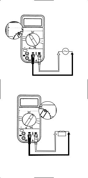
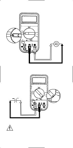
Measuring AC Voltage (VAC)
PHASE ROTATI
HZ-MFD-
VAC |
600 |
PHASE ROTATION-TRUE RMS |
|||
|
HZ-MFD-AUTO OFF |
|
|||
2000m |
200 |
VAC |
|
|
VDC |
|
600 |
600 |
|||
200m |
|
|
200 |
200 |
|
|
2000m |
|
20 |
||
|
200m |
|
|
||
|
|
|
|
|
2000m |
RST |
|
RST |
|
|
200m |
|
|
Hz |
|
|
ADC |
|
|
|
|
|
|
|
|
200M |
|
|
AAC |
|
|
|
|
|
|
|
|
20M |
|
|
200 |
|
|
|
|
|
|
|
|
200k |
|
|
2k |
|
|
|
20k |
20k |
MFD |
|
|
|
2k 200 |
|
|
|
|
2A |
|
|
|
|
|
MFD |
|
CAT. LLL 600V |
|
|
|
|
|
|
|
|
|
|
COM |
|
V |
|
|
|
|
! |
|
|
|
R/L1 |
|
600V |
|
|
|
|
|
MAX |
|
|
|
|
|
350V/15 |
|
|
|
|
|
SEC FOR |
|
|
|
|
|
200mV |
|
|
|
|
|
RANGE |
|
Red
Black
Measuring DC Voltage (VDC)
TION-TRUE RMS
-AUTO OFF
|
|
|
600 |
VDC |
PHASE ROTATION-TRUE RMS |
200 |
|||
|
HZ-MFD-AUTO OFF |
|
|
|
VAC |
600 |
600 |
VDC |
2000m |
200 |
|
|||
200m |
|
|
2000m |
|
|
|
|
|
|
RST |
|
|
|
ADC |
Hz |
|
|
ADC |
|
|
|
|
|
|
200M |
|
|
|
|
20M |
|
|
200 |
|
|
|
|
|
|
|
20k |
20k |
MFD |
|
|
2k 200 |
|
|
|
2A |
|
|
|
|
MFD |
|
CAT. LLL 600V |
|
|
|
|
|
+ - |
|
|
COM |
|
V |
|
R/L1 |
|
! |
|
|
|
|
600V |
|
|
|
|
MAX |
|
|
|
|
350V/15 |
|
|
|
|
SEC FOR |
|
|
|
|
200mV |
|
|
|
|
RANGE |
|
|
Red
Black
Page 4
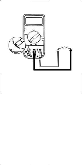
Measuring Resistance (Ohms)
|
PHASE ROTATION-TRUE RMS |
||||
|
|
HZ-MFD-AUTO OFF |
|
||
|
VAC |
600 |
|
600 |
VDC |
|
|
200 |
|
200 |
|
|
2000m |
|
|
20 |
|
|
200m |
|
|
|
|
|
|
|
|
2000m |
|
|
|
|
|
|
|
|
RST |
|
|
|
200m |
|
Hz |
|
|
|
ADC |
|
|
|
|
|
|
Hz |
200M |
|
|
|
AAC |
|
|
|
|
|
|
|
20M |
|
|
|
200 |
200M |
|
|
|
|
|
200k |
|
|
|
2k |
|
|
|
|
|
||
20M |
|
20k |
200 |
20k |
MFD |
|
2k |
|
|||
|
2A |
|
|
|
|
|
MFD |
|
|
CAT. LLL 600V |
|
20k |
|
|
|
|
|
|
|
COM |
|
V |
|
2k |
200 |
|
|
||
|
|
! |
|
||
|
|
|
|
|
|
|
R/L1 |
|
|
600V |
|
|
|
|
|
MAX |
|
|
|
|
|
350V/15 |
|
|
|
|
|
SEC FOR |
|
|
|
|
|
200mV |
|
|
|
|
|
RANGE |
|
Red
Black
Page 5
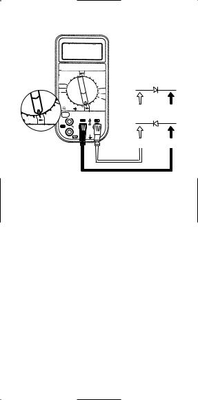
Testing Diodes
PHASE ROTATION-TRUE RMS
HZ-MFD-AUTO OFF
|
VAC |
200 |
600 |
VDC |
|
|
|
|
600 |
|
|
|
|
|
200m |
|
|
2000m |
Forward Bias |
|
|
|
|
|
|||
|
Hz |
|
|
200m |
+ |
- |
|
RST |
|
|
|
|
|
|
|
|
|
ADC |
|
|
|
200M |
|
|
AAC |
|
|
|
|
|
|
|
|
|
|
20M |
|
|
200 |
|
|
|
|
|
|
|
|
|
|
200 |
20k |
20k |
MFD |
|
|
|
2k |
200 |
|
|
||
|
2A |
|
|
|
Reverse Bias |
|
|
20k |
|
|
|
||
|
MFD |
|
CAT. LLL 600V |
|
|
|
|
MF |
|
|
- |
+ |
|
200 |
|
! |
|
|||
|
|
COM |
V |
|
|
|
|
R/L1 |
|
600V |
|
|
|
|
|
|
MAX |
|
|
|
|
|
|
350V/15 |
|
|
|
|
|
|
SEC FOR |
|
|
|
|
|
|
200mV |
|
|
|
|
|
|
RANGE |
|
|
|
Red
Black
1.Turn off power to the device or circuit that is being tested and discharge all capacitors.
2.Check the forward bias of the diode by connecting the red test probe to the anode (+) and the black test probe to the cathode (-) of the diode. Read the forward voltage drop on the meter display.
2.1A good silicone diode will result in a reading from about 0.3 - 0.7 V.
2.2A short is indicated by a continuous beep and a reading of .000 V.
2.3An open is indicated by an “OL” reading.
3.Check the reverse bias of the diode by reversing the test lead connections to the diode (red probe to cathode and black probe to anode).
3.1A reading of “OL” indicates reverse blocking and a good diode.
3.2A reading of .000 V and a continuous beep indicates high reverse leakage current or a short.
Page 6
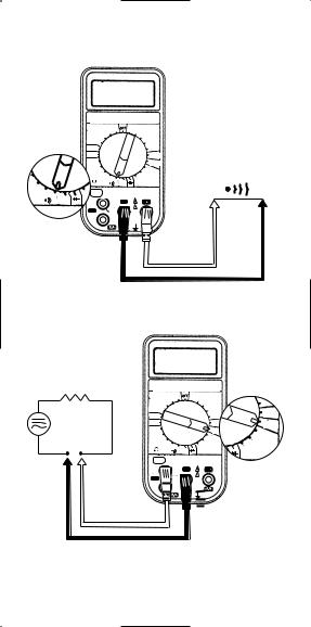
Testing for Continuity
(beeps at resistance <30Ω )
|
PHASE ROTATION-TRUE RMS |
|||
|
|
HZ-MFD-AUTO OFF |
|
|
|
VAC |
600 |
600 |
VDC |
|
|
200 |
200 |
|
|
2000m |
|
20 |
|
|
200m |
|
|
|
|
|
|
|
2000m |
|
RST |
|
|
200m |
|
Hz |
|
|
ADC |
|
|
|
|
|
|
200M |
|
|
AAC |
|
|
|
|
|
|
20M |
|
|
200 |
|
|
|
|
|
M |
200k |
|
|
2k |
|
|
20k |
20k |
MFD |
|
|
2k 200 |
|
|
20k |
2A |
|
|
|
20k MFD |
|
CAT. LLL 600V |
|
|
2k |
200 |
COM |
|
V |
|
|
|
||
!
R/L1
600V D MAX
350V/15 SEC FOR 200mV RANGE
Red
Black
Measuring Current (AAC and ADC)
PHASE ROTATION-TRUE RMS
HZ-MFD-AUTO OFF
VAC |
600 |
|
600 |
VDC |
|
2000m |
200 |
|
200 |
|
200m |
|
|
|
20 |
||
200m |
|
|
|
|
|
|
|
|
|
2000m |
ADC |
RST |
|
|
|
200m |
|
Hz |
|
|
|
ADC |
AAC |
|
|
|
|
||
200M |
|
|
|
AAC |
|
|
|
|
|
|
|
20M |
|
|
|
200 |
200 |
|
|
|
|
|
|
200k |
|
|
|
2k |
|
|
20k |
200 |
20k |
MFD |
20k |
|
2k |
|
|||
|
|
|
|
|
MFD |
|
|
|
CAT. LLL 600V |
|
|
|
|
|
|
V |
|
|
|
|
! |
|
|
|
|
|
600V |
|
|
|
|
|
MAX |
|
|
|
|
|
350V/15 |
|
|
|
|
|
SEC FOR |
|
|
|
|
|
200mV |
|
|
|
|
|
RANGE |
|
|
Page 7
Measuring Frequency (Hz)
200m
RST
Hz
200M
20M
PHASE ROTATION-TRUE RMS
HZ-MFD-AUTO OFF
VAC |
600 |
600 |
VDC |
2000m |
200 |
200 |
|
|
|
20 |
|
200m |
|
|
|
|
|
|
2000m |
RST |
|
|
200m |
Hz |
|
|
ADC |
|
|
|
|
200M |
|
|
AAC |
|
|
|
|
20M |
|
|
200 |
|
|
|
|
200k |
|
|
2k |
|
20k |
20k |
MFD |
|
2k 200 |
|
|
2A |
|
|
|
MFD |
|
CAT. LLL 600V |
|
|
|
|
|
|
COM |
|
V |
|
|
! |
|
R/L1 |
|
600V |
|
|
|
MAX |
|
|
|
350V/15 |
|
|
|
SEC FOR |
|
|
|
200mV |
|
|
|
RANGE |
|
Red
Black
Measuring Capacitance (MFD)
PHASE ROTATION-TRUE RMS
HZ-MFD-AUTO OFF
VAC |
600 |
|
600 |
VDC |
|
2000m |
200 |
|
200 |
|
200m |
|
|
|
20 |
||
200m |
|
|
|
2000m |
|
|
|
|
|
ADC |
|
RST |
|
|
|
200m |
|
Hz |
|
|
|
ADC |
AAC |
|
|
|
|
||
200M |
|
|
|
AAC |
|
|
|
|
|
|
|
20M |
|
|
|
200 |
200 |
|
|
|
|
||
200k |
|
|
|
2k |
|
|
20k |
|
20k |
|
|
|
2k |
200 |
|
MFD |
20k |
|
|
|
|
200 |
MFD |
|
|
|
CAT. LLL 600V |
|
|
|
|
|
|
V |
|
|
|
|
! |
|
|
|
|
|
600V |
|
|
|
|
|
MAX |
|
|
|
|
|
350V/15 |
|
|
|
|
|
SEC FOR |
|
|
|
|
|
200mV |
|
|
|
|
|
RANGE |
|
|
Red
Black
Turn off power and discharge the capacitor before attempting a measurement.
Page 8
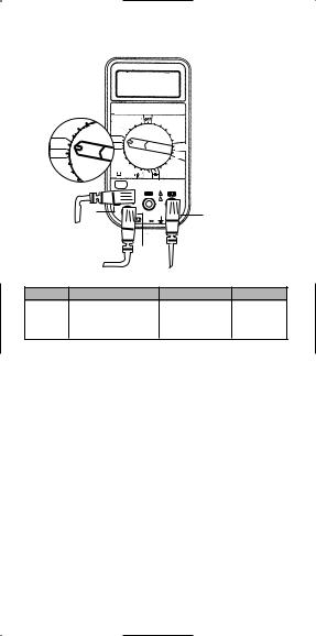
Indicating Phase Rotation (RST)
PHASE ROTATION-TRUE RMS
HZ-MFD-AUTO OFF
|
200 |
VAC |
600 |
|
600 VDC |
|
|
|
|
2000m |
200 |
|
200 |
|
|
|
|
|
|
|
20 |
|
|
200m |
|
200m |
|
|
|
|
|
|
|
|
|
2000m |
|
||
|
|
RST |
|
|
|
200m |
|
RST |
|
Hz |
|
|
|
ADC |
|
|
|
|
|
|
|
|
|
Hz |
|
200M |
|
|
|
AAC |
|
|
|
20M |
|
|
|
200 |
|
200M |
|
|
|
|
|
|
|
|
200k |
|
|
|
2k |
|
|
|
|
|
|
|
|
||
20M |
|
|
20k |
200 |
20k |
MFD |
|
|
|
2k |
|
|
|||
|
|
2A |
|
|
|
|
|
|
|
MFD |
|
|
CAT. LLL 600V |
|
|
|
|
|
|
|
|
|
|
|
|
|
|
COM |
|
V |
|
|
|
|
|
|
! |
|
|
|
|
R/L1 |
|
|
600V |
|
|
|
|
|
|
|
MAX |
|
|
|
|
R |
|
|
350V/15 |
|
|
|
|
|
|
SEC FOR |
|
|
|
|
|
|
|
200mV |
T |
|
|
|
|
|
|
RANGE |
|
|
|
|
|
|
S |
|
|
|
|
Function |
Frequency Range |
Voltage Range |
|
||||
Phase |
50 Hz to 450 Hz |
|
|
80V to 500V |
LCD indicates |
||
Rotation |
|
|
sequence of |
||||
Indicator |
|
|
|
|
|
|
three-phases. |
To Determine Phase Rotation (RST):
This test function correctly identifies each of the 3-Phases in a power panel as R, S, T. Note: The displayed numerical value has no meaning when performing this procedure. Maximum 3 phase voltage allowed in this mode is 500 VAC.
1.Turn power off to the circuit that is to be tested.
2.Place the function switch on the meter to “RST.”
3.Plug the test leads into the meter inputs labeled as R, S, T in the diagram above. Note that test lead colors are insignificant.
4.Attach the three test leads to each of the 3-Phase cables in any order.
5.Turn the power on.
6.If all three supply lines have power, the meter will indicate a R, S, T (in the upper left corner).
Page 9

Indicating Phase Rotation (continued)
7.If the meter indicates “OK” in the display (upper left-hand side),
a.Turn power off to the circuit.
b.Label each phase cable as R, S, or T following the test lead connections to the labeled meter inputs.
8.If the meter indicates an  message in the display (lower left-hand side), the phase rotation is counter-clockwise.
a.Turn power off to the circuit.
b.Switch any two test lead connections to the phase cables.
c.Turn power on.
d.The meter will now indicate “OK” in the display.
e.Turn the power off.
f.Label each phase cable as R, S, or T following the test lead connections to the labeled meter inputs.
Page 10
Specifications:
Function |
Range |
Resolution |
Accuracy |
|
AC Voltage |
200.0 mV |
.1 mV |
±(2.0% + 4) |
|
(True RMS) |
2000 mV |
1 mV |
||
50 to 500Hz |
||||
|
200.0 V |
.1V |
||
|
all ranges |
|||
|
600 V |
1 V |
||
|
|
Function |
Range |
Resolution |
Accuracy |
DC Voltage |
200.0 mV |
.1 mV |
|
|
2000 mV |
1 mV |
± (0.5% +1) |
|
20.00 V |
.01 V |
all ranges |
|
200.0 V |
.1 V |
|
|
600 V |
1 V |
|
Function |
Range |
Resolution |
Accuracy |
Resistance |
200.0Ω |
.1Ω |
± (1.0% + 4) |
|
2.000kΩ |
.001kΩ |
± (1.0% + 4) |
|
20.00kΩ |
.01kΩ |
± (1.0% + 4) |
|
200.0kΩ |
.1kΩ |
± (1.0% + 4) |
|
20.00MΩ |
.01MΩ |
± (2.0% + 4) |
|
200.0MΩ |
.1 MΩ |
± (5.0% -10,+10) |
Function |
|
Range |
|
Resolution |
|
Accuracy |
|
||||
Diode Test |
|
2 VDC |
|
|
1 mV |
± (3.0% + 1) |
|
||||
|
|
|
|
|
|
|
|
|
|
|
|
Function |
|
Range |
|
|
|
Resolution |
|
Accuracy |
|
||
AC Current |
|
2.000 A |
|
|
|
.001 A |
|
± (3.0% + 4) |
|
||
(True RMS) |
|
|
|
|
|
50 to 500 Hz |
|
||||
|
|
|
|
|
|
|
|
|
|||
DC Current |
|
2.000 A |
|
|
|
.001 A |
|
±(2.5%+4) |
|
||
|
|
|
|
|
|
|
|
|
|
|
|
Function |
|
|
Range |
|
Resolution |
|
|
Accuracy |
|
||
Frequency |
|
10 Hz to 100 kHz |
|
.001 kHz |
±(0.1% + 3 digits) |
|
|||||
|
Sensitivity : 3.5 V rms |
|
|
|
|
|
|
||||
*DC Voltage higher than 3.5 V rms |
|
|
|
|
|
|
|||||
|
|
|
|
|
|
|
|
|
|
|
|
Function |
|
Range |
|
Resolution |
|
Accuracy |
|
||||
Capacitance |
|
200.0 µF |
|
.1 µF |
± (4.0% + 10) |
|
|||||
(MFD) |
|
2k µF |
|
1 µF |
|
||||||
|
|
|
20k µF |
|
10 µF |
|
all ranges |
|
|||
|
|
|
|
|
|
|
|
|
|
|
|
Page 11
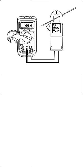
Accessories
Red
Black
Optional Clamp Adaptor To Use Accessories:
Clamp adapters allow multimeters the versatility to measure large amounts of current safely through a clamphead. IDEAL clamp adapters convert amps measured into mV signals that the multimeter can display. Since the clamp adapters convert the amps measurement into mVAC, the clamp adapter leads must be inserted into the volts and com inputs and the meter must be set to the mVAC range. The conversion ratio is one-to-one (1Amp=1mV). So, when the meter displays 50.0 mV, the clamp adapter is measuring 50.0 Amps.
Instructions for Use:
1.Connect the Current Clamp to the digital multimeter by plugging the red test lead into the Volts input and the black test lead into the COM input on the meter.
(See diagram above.)
2.a. Select 200 mVAC range for measuring less than 200 Amps. b. Select 2000 mVAC range for measuring more than 200 Amps.
3.Snap the jaw of the current clamp around one of the current carrying conductors.
4.Take the reading.
Page 12

General Specifications:
Indicators: Continuity: (30Ω ) indicated by a continuous “beep” within 100 msec. Low Battery indicator displayed in the LCD when battery is below operating range. Overrange: “OL” displayed.
Environmental: Operating temperature 32°F to 122°F, storage 0°F to 140°F with batteries removed, RH<70%.
LCD: 3.5 digits.
Size: 4.0”W x 7.5”H x 2.5”D Weight: 18 oz. including battery.
Battery life: >200 hours typical (9V NEDA 1604 type, JIS006P, IEC6F22 battery).
Accessories:Ω |
Comes with a pair of test leads ground lead with |
clip, |
|
Overload Protection: 600V for DCV, ACV, and phase indica-
tion. |
for capacitance, ohms, frequency and |
diode |
. Current protected by 2A/600V (6.35mm x 25.4mm) |
fuse model LA-3893 and 0.1A/250V (5mm x 20mm) fuse model
LA-3898. |
|
Auto |
Off: 25 minutes |
User
Regular operator maintenance of the multimeter consists of cleaning case and window, and battery replacement. All other repairs must be performed by a factory service center or other qualified instrument service personnel.
Cleaning Case and window
Periodically wipe the case with a damp cloth and detergent, allow dry completely before using; do not use abrasives or solvents.
Fuse
1.Disconnect the test leads and turn the meter off. Remove the leads from the front terminals.
2.Position the meter face down. Remove the screws from the case back. Lift the end of the case back until it gently unsnaps.
3.Remove the fuse by gently prying one end of the fuse loose and sliding the fuse out of the bracket.
4.Verify continuity across the fuse.
5. |
If |
fuse is blown, install a new fuse of the same size and rating. |
6. |
Replace the case top. Reinstall screws. |
|
Page 13

Battery Replacement
When the multimeter displays the 
 the battery must be replaced to maintain proper operation.
 WARNING
To prevent electrical shock hazard, turn off the multimeter and disconnect test leads before removing the back cover.
1.Disconnect the test leads and turn the meter off. Remove the test leads from the front terminals.
2.Position the meter face down. Remove the screws from the case bottom.
3.Lift the end of the case back until it gently unsnaps.
4.Lift the battery from the case back.
5.Replace battery.
6.Replace the case top. Reinstall screws.
LIFETIME LIMITED WARRANTY
This meter is warranted to the original purchaser against defects in material or workmanship. During the warranty period, IDEAL INDUSTRIES, INC. will, at its option, replace or repair the defective unit, subject to verification of the defect or malfunction.
This warranty does not apply to defects resulting from abuse, neglect, accident, unauthorized repair, alteration, or unreasonable use of the instrument.
Any implied warranties arising out of the sale of an IDEAL product, including but not limited to implied warranties of merchantability and fitness for a particular purpose, are limited to the above. The manufacturer shall not be liable for loss of use of the instrument or other incidental or consequential damages, expenses, or economic loss, or for any claim or claims for such damage, expenses, or economic loss.
State laws vary, so the above limitations or exclusions may not apply to you. This warranty gives you specific legal rights, and you may also have other rights which vary from state to state.
Page 14
 Loading...