


ND 4960-4 61-764-766-768 Ins 7/26/07 2:20 PM Page 1
#61-764 #61-766 #61-768
660A Clamp Meters w/TightSight™ Display
Instruction Manual
CAT.IV 600V |
660A |
CAT.III 1000V |
HOLD
V
61-766 |
V |
|
|
|
|
|
Ω |
|
MAX |
Hz |
|
|
66 |
|
MIN |
A |
|
|
660 OFF |
INRUSH
True RMS
750V00V 
DCAC |
AMPS |
|
TightSight™ Display
Read First: Safety Information
Understand and follow operating instructions carefully. Use the meter only as specified in this manual; otherwise, the protection provided by the meter may be impaired.
WARNING
To avoid possible electric shock, personal injury or death, follow these guidelines:
•Do not use if meter appears damaged. Visually inspect the meter to ensure case is not cracked and back case is securely in place.
•Inspect and replace leads if insulation is damaged, metal is exposed, or probes are cracked. Pay particular attention to the insulation surrounding the connectors.
•Do not use meter if it operates abnormally as protection maybe impaired.
•Do not use during electrical storms or in wet weather.
•Do not use around explosive gas, dust, or vapor.
•Do not apply more than the rated voltage to the meter.
•Do not use without the battery and the back case properly installed.
•Replace battery as soon as battery indicator 
 appears to avoid false readings.
•Remove the test leads from the circuit prior to removing battery cover.
•Do not attempt to repair this unit as it has no user-serviceable parts.
CAUTION
To protect yourself, think "Safety First":
•Voltages exceeding 30VAC or 60VDC pose a shock hazard so use caution.
•Use appropriate personal protective equipment such as safety glasses, face shields, insulating gloves, insulating boots, and/or insulating mats.
•Before each use:
-Perform a continuity test by touching the test leads together to verify the functionality of the battery and test leads.
-Use the 3 Point Safety Method. (1) Verify meter operation by measuring a known voltage. (2) Apply meter to circuit under test. (3) Return to the known live voltage again to ensure proper operation.
measurements.
.
applying the red test lead to voltage first.
probe tips as possible.
Page 2
ND 4960-4 61-764-766-768 Ins 7/26/07 2:20 PM Page 3
760 Series Common Features:
•Auto/manual ranging clamp meter
•TightSight™ bottom display
•Visual and selectable audible indication when voltage is present even when the meter is set on the wrong function for enhanced safety
•Measures 660 AAC Current
•Measures AC/DC Voltage & Resistance
•Audible continuity
•Bright, bold backlight
Model Specific Features:
•Large numbers and symbols displayed
•Inrush, max/min, data hold
•Selectable Auto power off and low battery indicator
•Tapered jaws for reaching into tight spaces
•Hook tip for easier wire separation
•Protective rubber boot
•Electronic overload protection on
all ranges
• Cat IV-600V/Cat III-1000V
•61-764 model is averaging sensing, rms calibrated
•61-766 model is true rms sensing, measures capacitance, frequency and lower currents with a 66 AAC range for troubleshooting motors and adjustable speed drives
•61-768 model is true rms sensing and measures DC current
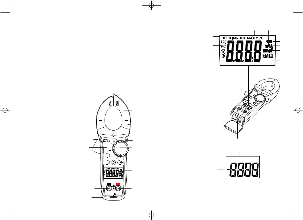
Features
1.Tapered jaws w/hook tip
2.Lever
3.Function Dial
4.Main Display (LCD)
5.Volts and resistance (V-Ω) input terminal
6.Common (COM) input terminal
7.TightSight™ bottom display
8.Protective rubber boot
9.Measuring Functions
10.High Voltage (Hi-V) warning
11.Data Hold
12.Max/min
13.Inrush Current
14.Backlight
15.Range ( )
)
Symbols on the Unit
• Warning - read the instruction manual
•Cat IV - 600V Safety category
•Cat III - 1000V Safety category
1
CAT.IV 600V |
660A |
CAT.III 1000V |
|
|
|
10 |
|
|
2 |
|
HOLD |
|
|
V |
11 |
||
|
61-766 |
|||
|
V |
|
||
9 |
|
3 |
||
|
Ω |
|||
12 |
MAX |
Hz |
14 |
|
66 |
||||
MIN |
|
|||
|
|
A |
660 OFF |
|
13 |
INRUSH |
|
15 |
|
|
|
True RMS |
||
|
|
|
4 |
|
|
COM |
V/Ω |
||
|
6 |
|
5 |
|
|
|
CAT.IV 600V |
||
CAT.III 1000V
MAX
|
1000V |
|
750V |
8 |
7 |
|
Page 3
Main Display Icons |
Main Display |
16.6600 count display
17.AC measurement
18.DC measurement
19.Polarity indicator for DC
20.Range ( )
)
21.Auto Power Off (APO)
22.Data Hold
23.Max/min
24.Inrush Current
25.Audible continuity
26.Volts
27.Amps
28.Farads
29.Ohms
30.Hertz
31.Low battery indicator
22 24
16
21
17
19
18
20
INRUSH
AC APO
0
23 26
31
27
28
29
 Hz 30
Hz 30
25
6 |
1-7 |
|
|
66 |
66  660
660
|
COM |
10 |
|
|
A |
|
|
|
|
|
20 |
|
|
|
|
|
|
|
30 |
|
|
CAT. |
|
|
|
V/ |
40 |
|
|
|
|
|
||
|
CAT.IIIIV |
600V |
|
|
|
|
|
1000VMAX1000V |
|
|
|
||
|
750V |
|
|
|
|
|
DCAC |
AMPS |
|
|
|
|
|
|
|
|
|
|
|
|
TightSight™ Display Icons
32.6600 count display
33.Polarity indicator for DC
34.DC measurement
35.AC measurement
36.Amps
TightSight™ Bottom Display
34 |
35 |
36 |
DCAC AMPS
32 33
Note: Only AC/DC amps units of measure are displayed in the TightSight™ display since primary use is for viewing current measurements in tight locations. The display will show numerical values only for other functions. The main display is to be used to view units of measure for all other functions.
Page 4
ND 4960-4 61-764-766-768 Ins 7/26/07 2:20 PM Page 5
OPERATION:
High Voltage Warning (HI-V)
The meter beeps and lights an LED when > 30V AC/DC voltage is present through the test leads of the meter. This enhanced safety feature alerts the user that dangerous voltage is present across the leads even if the meter is set on an incorrect function or range.
Notes: This features does not work through the clamp head as the clamp is intended to only measure current. Audible indication can be turned off by sliding the switch in battery compartment.
Auto/Manual Ranging Mode (  )
)
The meter defaults to autoranging mode to automatically select the best range to display the measurement. By pressing the Range (  ) button on the meter, the manual range mode will override the auto-ranging feature of the meter. A (
  ) appears in the upper left side of the display. Continue pressing the Range button until the desired range is obtained. Use this mode to access the mV range or to lock in a specific range for repeated measurements. To return to the autoranging mode, either depress the Range button for greater than 1 second or turn the meter off and then back on again.
INRUSH Feature (61-766, 61-768 models only)
The INRUSH function captures the starting current precisely in the beginning of the 100-milli second period. Press the “INRUSH” button to toggle into the INRUSH mode, and the “----”and “INRUSH” will be displayed. Clamp onto a single conductor and turn on the motor. Read the INRUSH current on the display. Depress the INRUSH button for more than 2 seconds to exit the INRUSH mode. Note: Minimum input range: >100 dgts. (66A range unspecified.)
Max/Min Feature
The Max records the maximum vaue measured over time while Min captures the minimum value measured over time. Press the Max/Min button to activate this feature and to toggle between Max, Min and MaxMin. “MAXMIN” displays the real time reading while still capturing max and min values over time. Depressing the max/min button for >2 sec. exits the mode. Note: To record max/min values over a time period >30 min, the Auto Power Off (APO) feature must be defeated.
Data Hold Feature
Press the Hold button on the side of the meter to toggle in and out of the data hold mode. “HOLD” appears in the upper left of the meter display when data hold is active. Use the data hold feature to lock a measurement reading on the display. Press the Hold button again to unlock the display and obtain a real-time reading.
ZERO Feature (61-768 model only)
The “ZERO” button is used to zero out the display before measuring DC current. Press the “ZERO” button to subtract out the non-zero number. Then, measure the DC amps. Pressing the “ZERO” button again causes the “ZERO” to flash and the original offset number to be displayed. Depress the “ZERO” button for >2 sec. to exit this mode.
Page 5
Relative Mode (61-764 model only)
Press “  ” button to enter the Relative mode. The “
 ” symbol is displayed, and the value on the display is subtracted and stored as a reference value. In the Relative mode, the value shown on the display is always the difference between the stored reference value and the present reading. Press the “
  ” button again to exit the Relative mode.
Selectable Auto Power Off (APO) Feature
The meter automatically powers itself down after about 30 minutes of no use. Press any button, and the meter will wake up and display the last reading taken before power down. This feature can be overridden by holding the Range ( ) button while turning the function switch from Off to any other position. When APO is defeated, the “APO” will be removed from the display. Turning the meter off will restore the APO default.
Backlight
Press the  button in the middle of the meter to turn the backlight on and off. The green backlight will remain lit for about 3 minutes before it automatically turns off to conserve battery power.
Note: Backlight consumes 4x the battery power.
INRU  SH
SH
66
Backlight on in all functions.
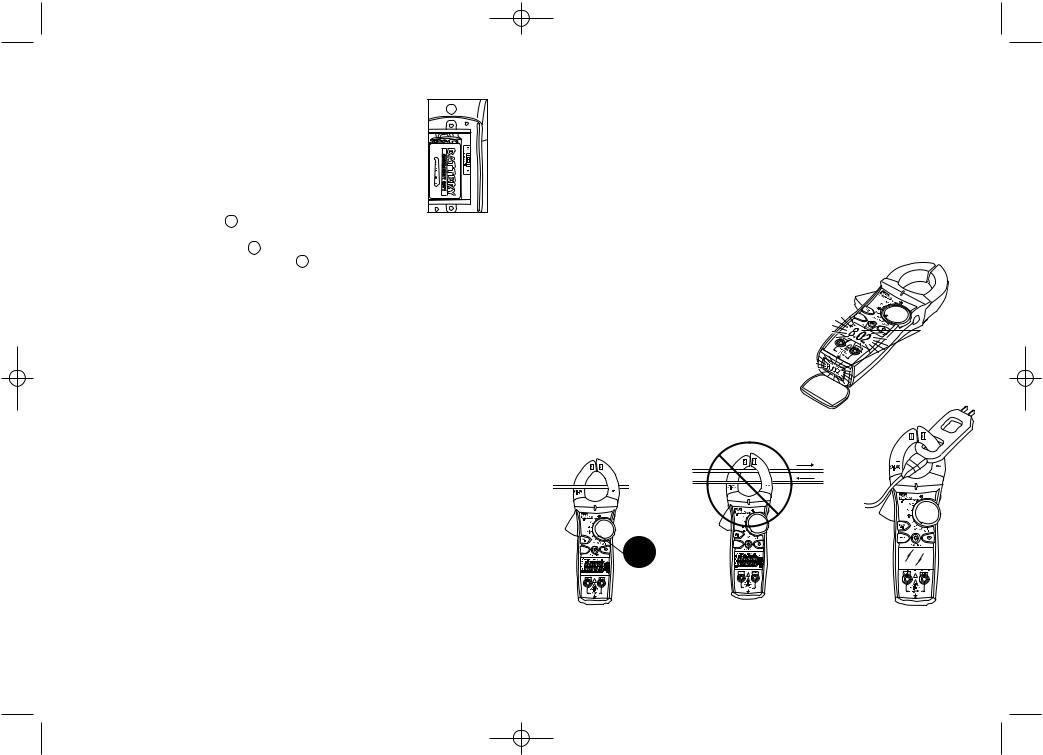
Measuring AC Current (Amps):
H
N
66
66
INRUSH
CORRECT |
INCORRECT |
CORRECT |
Single |
Currents |
Use with |
Conductor |
cancel |
line splitter |
only |
|
|
Note: 61-768 |
measures DC Current. |
|
|
Page 6 |
|

ND 4960-4 61-764-766-768 Ins 7/26/07 2:20 PM Page 7
Measuring Voltage:
66
 660
660 

INRUSH
AC |
DC Voltage |
Verifying Continuity (  ):
):
• Verify the circuit is de-energized.
• The meter will sense the level of resistance and beep if the resistance is less than 40 Ω to confirm that continuity is present.
66
660
INRUSH
Closed
Circuit
Measuring Capacitance (61-766):
66
 660
660 

INRUSH
Open
Circuit
Note: 660.0/750VAC/1000VDC are auto ranges while 6600mV/6.600/66.00 are manual ranges.
Measuring |
|
• Verify the circuit |
to obtain accurate measurements. |
66
 660
660 

INRUSH
66
 660
660 

INRUSH
Note: If “disc” is displayed, then voltage exists in capacitor. Discharge capacitor and re-initiate test.
Page 7 |
Page 8 |
ND 4960-4 61-764-766-768 Ins 7/26/07 2:20 PM Page 9
Measuring Frequency (61-766):
66
660

INRUSH
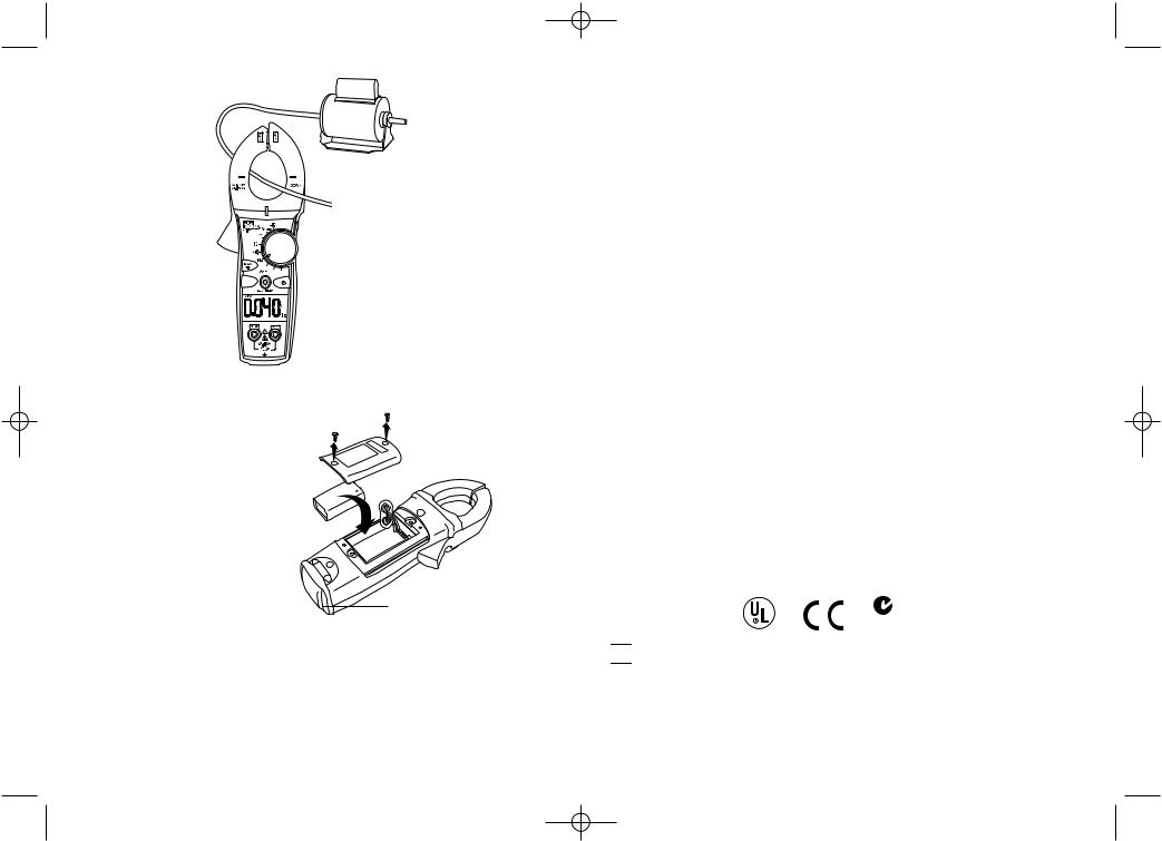
Battery Replacement:
• Ensure test leads are disconnected from circuit or components.
• Remove test leads from input jacks on meter.
•Remove the two screws from the battery cap.
•Remove the battery cap.
•Replace battery with a new 9V battery.
•Assemble the battery cap to the meter and re-tighten the screws.
Maintenance:
Clean the case with a damp cloth and mild detergent.
Service and Replacement Parts:
This unit has no user-serviceable parts.
Replacement boot is available.
Do not use abrasives or solvents.
For replacement parts or to inquire about service information contact IDEAL INDUSTRIES, INC. at 1-877-201-9005 or visit our website www.testersandmeters.com.
Specifications: |
|
|
|
|
|
|
Displays: |
3-3/4 digit LCD with 6600 counts for both displays |
|||||
Backlight: |
Green illumination with auto-off after 3 minutes |
|||||
Polarity: |
Automatic, positive implied, negative (-) polarity indication. |
|||||
Overrange: |
"OL" indication is displayed. |
|||||
Zero: |
Automatic |
|
||||
Measure Rate: |
Samples 2 times per second, nominal. |
|||||
Auto Power Off: |
Approximately after 30 minutes of non-use. |
|||||
Battery Life: |
200 hours continuous with Alkaline (61-764, 61-766) |
|||||
|
150 hours continuous with Alkaline (61-768) |
|||||
Low Battery Indication: |
The " |
|
|
" is displayed when battery voltage drops below |
||
|
|
|||||
|
operating level. |
|
||||
Power Supply: |
(1) 9V battery (NEDA 1604, JIS 006P, IEC 6F22) |
|||||
|
Includes an isolated battery compartment. |
|||||
Accuracy: |
Stated accuracy at 23°C ±5°C, <75% R.H. |
|||||
Temperature |
0.1 x (specified accuracy) per °C, |
|||||
Coefficient: |
(0°C to 18°C, 28°C to 50°C). |
|||||
Altitude: |
6561.7 ft. (2000m) |
|
||||
Operating Environment: 32°F to 122°F (0°C to 50°C) at < 70% R.H. |
||||||
Storage Environment: |
-4°F to 140°F (-20°C to 60°C) at < 80% R.H. without battery |
|||||
Jaw Opening: |
Accepts a 1.42" (36mm) conductor |
|||||
Dimensions: |
8.7”H x 3.1”W x 1.8”D (222mmH x 80mmW x 45.5mmD) |
|||||
Weight: |
12.3 oz |
(350g) including battery |
||||
Accessories included: |
Carrying Case, Test Leads with alligator clip, (1) 9V |
|||||
|
battery, operating instructions. |
|||||
Safety: |
Complies with UL61010-1, UL61010-2-032, UL61010-2-031 |
|||||
|
EN61010-1, EN61010-2-032, EN61010-031 specifications, |
|||||
|
Cat IV-600V/Cat III-1000V. |
|||||
|
C |
US |
|
N12966 |
||
|
|
|||||
|
|
|||||
|
|
|
|
|
|
|


 Double Insulation
Instrument has been evaluated and complies with insulation category IV (overvoltage category IV). Pollution degree 2 in accordance with IEC-644. Indoor use.
Page 9 |
Page 10 |
ND 4960-4 61-764-766-768 Ins 7/26/07 2:20 PM Page 11
Ranges & Accuracies:
AC Converter: 61-764 model is averaging sensing, rms calibrated 61-766, 61-768 models are true rms sensing.
Accuracy: Accuracy is specified as +/-(a percentage of the reading + a fixed amount) at 23°C±5°C (73.4°F ± 9°F), less than 75% relative humidity.
Temperature Coefficient: 0.1 times the applicable accuracy specification per degree C from 0°C to 18°C and 28°C to 50°C (32°F to 64°F and 82°F to 122°F)
Function |
Range and |
|
Accuracy |
|
Overload |
||
|
|
|
|||||
Resolution |
61-764 |
61-766 |
61-768 |
Protection |
|||
|
|||||||
|
|
|
|
||||
|
66.00A |
(50-60Hz) |
1.7% + 8 |
1.7% + 10 |
N/A |
|
|
|
|
|
|
|
|
|
|
AC Current* |
66.00A |
(60-400Hz) |
3.0% + 8 |
3.0% + 10 |
N/A |
660 AAC |
|
|
|
|
|
|
|||
660.0A |
(50-60Hz) |
1.7% + 8 |
1.7% + 10 |
2.0% +10 |
|||
|
|
||||||
|
|
|
|
|
|
|
|
|
660.0A |
(60-400Hz) |
3.0% + 8 |
3.0% + 10 |
3.0% +10 |
|
|
|
|
|
|
|
|
|
|
DC Current |
660.0A |
|
N/A |
N/A |
2.0% + 5 |
660 ADC |
|
|
|
|
|
|
|
|
|
|
660.0m |
(50-60Hz) |
|
1.7% + 8 |
|
|
|
AC Voltage* |
6.600/66.00/660.0V |
1.2% + 8 (50~100Hz) |
1000VDC or |
||||
1.5% + 8 (100~400Hz) |
750VAC rms |
||||||
|
|
|
|||||
|
750V |
(50-400Hz) |
|
1.5% + 8 |
|
|
|
|
|
|
|
|
|
|
|
DC Voltage |
660.0mV |
|
|
1.0% + 2 |
|
1000VDC or 750 VAC rms |
|
|
|
|
|
|
|||
6.600/66.00/660.0/1000V |
|
0.5% + 2 |
|
||||
|
|
|
|
||||
|
|
|
|
|
|
||
|
660.0/6.600k/66.00k/400.0kΩ |
|
1.0% + 4 |
|
|
||
|
|
|
|
|
|
|
|
Resistance |
4.000MΩ |
|
|
5.0% + 4 |
|
600 VDC or AC rms |
|
|
|
|
|
|
|
|
|
|
10.00MΩ |
|
|
12.0% + 5 |
|
|
|
|
|
|
|
|
|
||
Capacitance** |
6.600µ/66.00µ/660.0µ F |
N/A |
3.0% + 10 |
N/A |
600 VDC or AC rms |
||
|
|
|
|
|
|
|
|
|
20 - 400 Hz |
|
|
|
|
|
|
|
|
|
|
|
|
660 AAC |
|
Frequency*** |
Sensitivity is 20-100Hz (≥ 5A) |
N/A |
0.1% + 3 |
N/A |
|||
600 VDC or AC rms |
|||||||
|
|
100-400 Hz (≥ 10A) |
|
|
|
||
|
|
|
|
|
|
||
|
|
|
|
|
|
||
Continuity |
Audible indication < 40Ω |
• |
• |
• |
600 VDC or AC rms |
||
|
|
|
|
|
|||
Response time: 100ms |
• |
• |
• |
||||
|
|
||||||
|
|
|
|
|
|
|
|
*Accuracy stated for crest factor ≤ 3 at full scale and ≤ 6 at half scale. **Measuring time: < 3s on 6.6µ - 66µF ranges ; < 6s on 660µF range
***Frequency can be measured through clamp head. Input impedance: 1M.Ω
Page 11
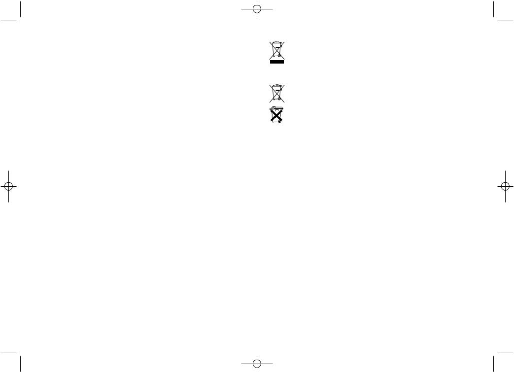
Dispose of waste electrical and electronic equipment
In order to preserve, protect and improve the quality of environment, protect human health and utilize natural resources prudently and rationally, the user should return unserviceable product to relevant facilities in accordance with statutory regulations. The crossed-out
wheeled bin indicates the product needs to be disposed separately and not as municipal waste.
Disposal of used batteries/accumulators!
The user is legally obliged to return used batteries and accumulators. Disposing used batteries in the household waste is prohibited! Batteries/accumulators containing hazardous substances are marked with the crossed-out wheeled bin. The symbol indicates that the product is forbidden to be disposed via the domestic refuse. The chemical symbols for the respective hazardous substances are Cd = Cadmium, Hg = Mercury, Pb = Lead.
You can return used batteries/accumulators free of charge to any collecting point of your local authority, our stores, or where batteries/accumulators are sold. Consequently you comply with your legal obligations and contribute to environmental protection.
Warranty Statement:
This tester is warranted to the original purchaser against defects in material and workmanship for two years from the date of purchase. During this warranty period, IDEAL INDUSTRIES, INC. will, at its option, replace or repair the defective unit, subject to verification of the defect or malfunction. This warranty does not apply to defects resulting from abuse, neglect, accident, unauthorized repair, alteration, or unreasonable use of the instrument.
Any implied warranties arising out of the sale of an IDEAL product, including but not limited to implied warranties of merchantability and fitness for a particular purpose, are limited to the above. The manufacturer shall not be liable for loss of use of the instrument or other incidental or consequential damages, expenses, or economic loss, or for any claim or claims for such damage, expenses or economic loss.
State laws vary, so the above limitations or exclusions may not apply to you. This warranty gives you specific legal rights, and you may also have other rights which vary from state to state.
Warranty does not cover batteries.
IDEAL INDUSTRIES, INC.
Sycamore, IL 60178
Technical Hotline: |
877- 201-9005 |
www.testersandmeters.com |
|
ND 4960-4 |
Made in Taiwan |
 Loading...