


USER GUIDE
LOGIC+ COMBI
C24 C30 C35
When replacing any part on this appliance, use only spare parts that you can be assured conform to the safety and performance specification that we require.
Do not use reconditioned or copy parts that have not been clearly authorised by Ideal Boilers.
For the very latest copy of literature for specification and maintenance practices visit our website www.idealboilers.com where you can download the relevant information in PDF format.
For alternative languages in our User Guides please visit our website www.idealboilers.com
July 2018
UIN 215419 A07
CONTENTS
1. Introduction ................................................... |
3 |
3. |
System Water Pressure................................. |
7 |
Safety............................................................... |
3 |
4. |
Condensate Drain.......................................... |
8 |
Electricity Supply.............................................. |
3 |
5. |
General Information....................................... |
9 |
Important Notes................................................ |
3 |
|
Boiler Pump...................................................... |
9 |
2. Boiler Operation............................................. |
4 |
|
Minimum Clearances....................................... |
9 |
Controls Diagram............................................. |
4 |
|
Escape of Gas.................................................. |
9 |
To Start the Boiler............................................. |
4 |
|
Cleaning........................................................... |
9 |
Operation Modes.............................................. |
5 |
|
Maintenance..................................................... |
9 |
Preheat Domestic Hot Water........................... |
5 |
6. |
Points for the Boiler User............................ |
10 |
Control of Water Temperature.......................... |
5 |
|
Troubleshooting............................................... |
11 |
Efficient Heating System Operation................. |
6 |
7. |
Display Functions - Normal Operation....... |
13 |
Weather Compensation................................... |
6 |
8. |
Display Functions - Settings Changed...... |
13 |
Boiler Frost Protection...................................... |
6 |
9. |
Display Functions - Fault Messages..... |
14-18 |
Boiler Restart................................................... |
6 |
|
|
|
Mains Power Off............................................... |
6 |
|
|
|
All Gas Safe Register installers carry a Gas Safe Register ID card, and have a registration number. Both should be recorded in the Benchmark Commissioning Checklist. You can check your installer by calling Gas Safe Register direct on 0800 4085500.
Ideal Boilers is a member of the Benchmark scheme and fully supports the aims of the programme. Benchmark has been introduced to improve the standards of installation and commissioning of central heating systems in the UK and to encourage the regular servicing of all central heating systems to ensure safety and efficiency.
THE BENCHMARK SERVICE INTERVAL RECORD MUST BE COMPLETED AFTER EACH SERVICE
2

1.INTRODUCTION
The Logic + Combi C is a combination boiler providing both central heating and instantaneous domestic hot water. Featuring full sequence automatic ignition and fan assisted combustion.
Due to the high efficiency of the boiler, condensate is produced from the flue gases and this is drained to a suitable disposal point through a plastic waste pipe at the base of the boiler. A condensate
‘plume’ will also be visible at the flue terminal.
Safety
CURRENT GAS SAFETY (INSTALLATION & USE) REGULATIONS OR RULES IN FORCE.
In your own interest, and that of safety, it is the law that this boiler must be installed by a Gas Safe Registered Engineer, in accordance with the above regulations.
In IE, the installation must be carried out by a Registered Gas Installer (RGII) and installed in accordance with the current edition of I.S. 813 “Domestic Gas Installations”, the current Building Regulations and reference should be made to the current ETCI rules for electrical installation.
It is essential that the instructions in this booklet are strictly followed, for safe and economical operation of the boiler.
ELECTRICITY SUPPLY
This appliance must be earthed.
Supply: 230 V ~ 50 Hz. The fusing should be 3A.
IMPORTANT NOTES
• This appliance must not be operated without the casing correctly fitted and forming an adequate seal.
• If the boiler is installed in a compartment then the compartment MUST NOT be used for storage purposes.
• If it is known or suspected that a fault exists on the boiler then it MUST NOT BE USED until the fault has been corrected by a Gas Safe Registered Engineer or in IE a Registered Gas Installer (RGII).
• Under NO circumstances should any of the sealed components on this appliance be used incorrectly or tampered with.
• This appliance can be used by children 8 years and above. Also persons with reduced physical, sensory or mental capabilities, or lack of experience
and knowledge, provided they have been given supervision or instruction concerning use of the appliance in a safe way and understand the hazards involved. Children shall not play with the appliance. Cleaning and user maintenance shall not be made by children without supervision.
3

2.BOILER OPERATION
Legend
A.Domestic Hot Water Temperature Knob
B.Central Heating Temperature Knob
C.Mode Knob
D.Boiler Status Display
E.Burner ‘on’ Indicator
F.Central Heating Economy Setting
G.Pressure Gauge
|
|
|
|
BOILER |
|
|
|
|
e OFF |
MIN |
|
MAX |
MIN |
MAX |
|
|
|
|
MODE |
G |
A |
E D |
B F |
C |
TO START THE BOILER
If a programmer is fitted refer to separate instructions for the programmer before continuing.
Start the boiler as follows:
1.Set the mode knob (C) to ‘BOILER OFF’.
2.Set the Domestic Hot Water temperature knob (A) and Central Heating temperature knob (B) to ‘MAX’.
3.Ensure that all hot water taps are turned off.
4.Switch on electricity to the boiler and check that all external controls, e.g. programmer and room thermostat, are on.
5. Set the mode knob (C) to ‘ |
’ (winter). |
The boiler will commence ignition sequence, supplying heat to the central heating, if required.
Note. In normal operation the boiler status display (D) will display messages (see section 7).
Note. Boilerfrostprotection-boilerwillfireiftemperatureisbelow5ºC.
During normal operation the burner on symbol (E) will remain illuminated when the burner is lit. 
Note. If the boiler fails to light after five attempts the following fault messages will be displayed:
Ignition Lockout 1/2
Check Other Gas
Appliances Work
Restart Boiler
Restart Menu
Ignition Lockout 2/2
If Fault Persists
Contact Installer
Restart Menu
To restart the boiler, press restart. The boiler will repeat the ignition sequence. If the boiler still fails to light consult a Registered Gas Installer, or in IE a Registered Gas Installer (RGII).
4
OPERATION MODES
Winter Conditions - (Central Heating and Domestic Hot Water required)
Set the mode knob (C) ‘ |
’ (winter). |
The boiler will fire and supply heat to the radiators.
The domestic hot water preheat will operate with the preheat button set to ‘Preheat On’.
Summer Conditions - (Domestic Hot Water only required) Set the mode knob (C) to ‘  ’ (summer).
Set the central heating demand on the external controls to OFF.
The domestic hot water preheat will operate with the preheat button set to ‘Hot Water On’.
Boiler Off
Set the mode knob (C) to ‘BOILER OFF’. The boiler mains power supply must be left on to enable frost protection (see Frost Protection).
PREHEAT - DOMESTIC HOT WATER
The domestic hot water heat exchanger within the boiler can be kept preheated to provide faster delivery of hot water at the tap. This is achieved by pressing the preheat button to “Preheat On”.
The boiler will operate periodically for a few seconds to maintain the domestic hot water heat exchanger in a preheated condition. The average time period between operation is 90 minutes. This may vary considerably due to the surrounding ambient temperature of the boiler. The boiler will operate whenever there is a demand for domestic hot water.
If standard hot water delivery is satisfactory set the preheat to ‘Preheat Off’.
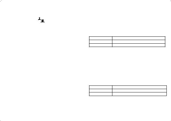
CONTROL OF WATER TEMPERATURE Domestic Hot Water
The domestic hot water temperature is limited by the boiler controls to a maximum temperature of 65ºC, adjustable via the domestic hot water temperature knob (B). At low DHW draw off rates the maximum temperature may exceed 65ºC.
Approximate temperatures for domestic hot water:
Knob Setting |
Hot Water Temperature (approx.) |
Minimum |
40ºC |
Maximum |
65ºC |
Due to system variations and seasonal temperature fluctuations domestic hot water flow rates/temperature rise will vary, requiring adjustment at the tap : the lower the flow rate the higher the temperature, and vice versa.
Central Heating
The boiler controls the central heating radiator temperature to a maximum of 80oC, adjustable via the central heating temperature knob (B).
Approximate temperatures for central heating:
Knob Setting |
Central Heating Radiator Temperature (approx.) |
Minimum |
30ºC |
Maximum |
80ºC |
For economy setting ‘  ’ refer to Efficient Heating System
Operation.
5

EFFICIENT HEATING SYSTEM OPERATION
The boiler is a high efficiency, condensing appliance which will automatically adjust its output to match the demand for heat. Therefore gas consumption is reduced as the heat demand is reduced.
The boiler condenses water from the flue gases when operating most efficiently. To operate your boiler efficiently (using less gas) turn the central heating temperature knob (B) to the ‘  ‘ position or lower. In winter periods it may be necessary to turn the knob towards the ‘MAX’ position to meet heating requirements. This will depend on the house and radiators used.
Reducing the room thermostat setting by 1ºC can reduce gas consumption by up to 10%.
WEATHER COMPENSATION
When the Weather Compensation option is fitted to the system then the central heating temperature knob (B) becomes a method of controlling room temperature. Turn the knob clockwise to increase room temperature and anti-clockwise to decrease room temperature. Once the desired setting has been achieved, leave the knob in this position and the system will automatically achieve the desired room temperature for all outside weather conditions.
BOILER FROST PROTECTION
The boiler is fitted with frost protection that operates in all modes, provided the power supply to the boiler is always turned on. If the water in the boiler falls below 5ºC, the frost protection will activate and run the boiler to avoid freezing. The process does not guarantee that all other parts of the system will be protected.
If a system frost thermostat has been installed, the boiler must
be set in winter mode, ‘  ’, for the system frost protection to run.
If no system frost protection is provided and frost is likely during a short absence from home it is recommended to leave the system heating controls or built in programmer (if fitted) switched on and run at a reduced temperature setting. For longer periods, the entire system should be drained.
BOILER RESTART
To restart the boiler, when directed in the listed fault messages (see section 9) press “Restart”. The boiler will repeat its ignition sequence. If the boiler still fails to start consult a Gas Safe Registered Engineer or in IE a Registered Gas Installer (RGII).
MAINS POWER OFF
To remove all power to the boiler the mains power switch must be turned off.
6
 Loading...