


IDEAL CLASSIC
RS30, RS40, RS50 & RS60
Wall Mounted, Balanced Flue
Gas Boilers
Installation & Servicing
CAUTION: To avoid the possibility of injury during the installation, servicing or cleaning of this appliance, care should be taken when handling edges of sheet steel components.
IMPORTANT: This appliance is for use with
NATURAL GAS ONLY.
Ideal Classic |
G.C. Appliance No. |
RS 30 |
41 429 35 |
RS 40 |
41 429 36 |
RS 50 |
41 429 37 |
RS 60 |
41 429 38 |
NOTE TO THE INSTALLER: LEAVE THESE INSTRUCTIONS ADJACENT TO THE GAS METER

|
GENERAL |
|
|
|
|
|
PERFORMANCE DATA |
||
|
Table 1- GENERAL DATA |
|
|
|
|
|
|
|
|
|
Boiler Size |
|
|
|
RS 30 |
|
RS 40 |
RS 50 |
RS 60 |
|
Main burner bar |
|
|
|
Aeromatic |
|
Aeromatic |
Aeromatic |
|
|
|
|
|
|
AC 19/123 263 |
AC 19/123 262 |
AC 19/123 261 |
||
|
Gas control |
|
|
|
|
HONEYWELL V 4700E 1072, 240V. |
|||
|
Burner Injector |
|
|
BRAY |
Cat 10 |
|
Cat 10 |
Cat 10 |
Cat 10 |
|
|
|
|
|
Size 750 |
|
Size1050 |
Size 1350 |
Size 1600 |
|
Pilot injector |
|
|
|
|
|
HONEYWELL 45900421 - 001 |
|
|
|
|
|
|
|
|
|
(STAMPED 38/36A) |
|
|
|
Gas supply connection |
|
|
(in. BSP) |
|
|
Rc 1/2 (1/2) |
|
|
|
Flow connections - PUMPED & GRAVITY |
|
|
|
|
22 mm copper |
|
||
|
|
|
|
|
(Gravity must be increased to 28 mm at the boiler) |
||||
|
Return connections - PUMPED & GRAVITY |
|
|
|
|
22 mm copper |
|
||
|
|
|
|
|
(Gravity must be increased to 28 mm at the boiler) |
||||
|
Maximum static water head |
|
|
m (ft.) |
|
|
30.5 (100) |
|
|
|
Minimum static water head |
|
|
m (ft.) |
|
|
0.45 (1.5) |
|
|
|
Electrical supply |
|
|
|
|
|
240 V ~ 50 Hz |
|
|
|
External fuse rating |
|
|
|
|
|
|
3 A |
|
|
Water content |
|
|
litre (gal.) |
2.7 (0.6) |
|
3.65 (0.8) |
3.65 (0.8) |
4.6 (1.0) |
|
Dry weight |
|
|
kg (lb.) |
33.0 (72.6) |
|
39.0 (86.0) |
39.0 (86.0) |
44.0 (97.0) |
|
Maximum installation weight |
|
|
kg (lb.) |
28.0 (61.6) |
|
34.0 (75.0) |
34.0 (75 0) |
40.5 (89.0) |
|
Boiler size |
Height |
|
mm (in.) |
|
|
600 (23.6) |
|
|
|
|
Width |
|
mm (in.) |
|
|
380 (15 0) |
|
|
|
|
Depth |
|
mm (in.) |
|
|
300 (11.8) |
|
|
|
|
|
|
|
|
|
|
|
|
|
Table 2- PERFORMANCE DATA |
|
|
|
|
|
|
|
|
|
|
|
|
|
|
|
|
|
|
|
Boiler Size |
|
|
|
RS 30 |
|
RS 40 |
RS 50 |
RS 60 |
|
|
|
|
|
|
|
|
|
|
|
Boiler input |
MINIMUM |
|
kW |
5.8 |
|
11.3 |
15.0 |
18.8 |
|
To obtain gas consumption |
|
|
(Btu/h) |
(19 800) |
|
(38 500) |
(51 200) |
(64 100) |
|
(a) For l/s; divide heat input |
Gas consumption |
l/s (ft3/h) |
0.15 (19 0) |
|
0.29 (37.0) |
0.39 (49.3) |
0.48 (61.7) |
|
|
(kW) by C.V. of the gas |
|
|
|
|
|
|
|
|
|
(MJ/m3). |
MID |
|
kW |
8.5 |
|
13.0 |
16.7 |
20.4 |
|
(b) For ft3/h; divide heat input |
|
|
(Btu/h) |
(29 000) |
|
(44 350) |
(56 850) |
(69 600) |
|
(Btu/h) by C.V. of the gas |
|
|
|
|
|
|
|
|
|
(Btu/ft3). |
Gas consumption |
l/s (ft3/h) |
0.22 (27.9) |
|
0.34 (42.7) |
0 43 (54.8) |
0.53 (67.0) |
|
|
Heat inputs are pre-set to the |
MAXIMUM |
|
kW |
11.0 |
|
14.7 |
18.30 |
22.0 |
|
highest nominal rating. |
|
|
(Btu/h) |
(37 500) |
|
(50 000) |
(62 500) |
(75 000) |
|
|
|
|
|
|||||
|
|
Gas Consumption |
l/s (ft3/h) |
0.28 (36.1) |
|
0.38 (48.2) |
0.47 (60.2) |
0.57 (72.2) |
|
|
Boiler output |
MINIMUM |
|
kW |
4.4 |
|
8.8 |
11.7 |
14.7 |
|
|
|
|
(Btu/h) |
(15 000) |
|
(30 000) |
(40 000) |
(50 000) |
|
|
MID |
|
kW |
6.6 |
|
10.3 |
13.2 |
16.1 |
|
|
|
|
(Btu/h) |
(22 500) |
|
(35 000) |
(45 000) |
(55 000) |
|
|
MAXIMUM |
|
kW |
8.8 |
|
11.7 |
14.7 |
17.6 |
|
|
|
|
(Btu/h) |
(30 000) |
|
(40 000) |
(50 000) |
(60 000) |
|
Burner setting pressure |
MINIMUM |
mbar (in.w.g.) |
4.5 (1.8) |
|
8.9 (3.6) |
9.7 (3 9) |
11.0 (4.4) |
|
|
(HOT) |
MID |
mbar (in.w.g.) |
9.5 (3.8) |
|
12.0 (4.8) |
12.1 (4.9) |
12.7 (5.1) |
|
2 |
|
MAXIMUM |
mbar (in.w.g.) |
16.0 (6.4) |
|
15.0 (6.0) |
14.5 (5.8) |
15.4 (6.2) |
|

GENERAL
INTRODUCTION
The Ideal Classic RS 30, RS 40, RS 50 and RS 60 are wall mounted, balanced flue, natural draught gas boilers. They are range rated to provide central heating outputs of 4.4kW
(15 000 Btu/h) to 8.8kW (30 000 Btu/h), 8.8kW (30 000 Btu/h) to 11.7kW (40 000 Btu/h), 11.7kW (40 000 Btu/h) to 14.7kW (50 000 Btu/h) and 14.7 kW (50 000 Btu/h) to 17.6kW
(60 000 Btu/h).
The boiler casing is of white enamelled mild steel with a removable controls pod containing a drop down door.
The boiler thermostat is located behind the controls access door, in the box mounted on the gas valve.
A Programmer Kit, which fits neatly within the casing, is available as an optional extra. Separate fitting instructions are included with this kit.
The boilers are suitable, as standard, for connection to open vented systems ONLY.
An Overheat Thermostat Kit is available to allow the boiler to be used on sealed water systems.
A complete Sealed System Module, which fits on top of the appliance, is also available as an optional extra.
The boiler is suitable for connection to pumped, open vented central heating systems; pumped central heating combined with pumped, or gravity, indirect domestic hot water systems; gravity or pumped, indirect domestic hot water supply systems.
See Frame 3 for details of the correct boiler tappings to use.
The boilers are suitable for the following wall thicknesses:
114 mm |
(4 1/2 in) |
to 191 mm |
(7 1/2in) |
229 mm |
(9 in) |
to 305 mm |
(12 in) |
318 mm |
(12 1/2 in) |
to 394 mm |
(15 1/2 in) and |
406 mm |
(16 in) |
to 584 mm |
(23in) |
Wall thicknesses outside of these sizes cannot be accommodated .
Gas Safety (Installation and Use) Regulations, 1984
It is law that all gas appliances are installed by competent persons (e.g. CORGI, identified by 
 ) in accordance with the above regulations. Failure to install appliances correctly could lead to prosecution. It is in your own interest and that of safety to ensure the law is complied with.
The installation of the boiler MUST also be in accordance with the latest l.E.E. Wiring Regulations, the local building regulations, bye-laws of the local water authority, the Building Regulations and the Building Standards (Scotland) and any relevant requirements of the local authority. Detailed recommendations are contained in the following
British Standard Codes of Practice:
BS 6891 Low pressure installation pipes.
BS 6798 Installation of gas fired hot water boilers of rated input not exceeding 60 kW.
BS 5449 Forced circulation hot water systems.
BS 5546 Installation of gas hot water supplies for domestic purposes (2nd Family Gases).
BS 5440:1 Flues (for gas appliances of rated input not exceeding 60 kW).
BS 5440:2 Ventilation (for gas appliances of rated input not exceeding 60 kW).
Manufacturer's notes must NOT be taken, in any way, as overriding statutory obligations.
INTRODUCTION - GAS SUPPLY
IMPORTANT. These appliances are certificated by the British Standards Institution for safety and performance. It is, therefore, important that no external control devices, e.g. flue dampers, economisers etc., are directly connected to these appliances - unless covered by these 'Installation and Servicing' instructions or otherwise recommended by Caradon Ideal Ltd. in writing. If in doubt please enquire.
Any direct reconnection of a control device not approved by Caradon Ideal Ltd. could invalidate the B.S.I. certification and the normal appliance warranty. It could also infringe the Gas Safety Regulations and the above regulations.
LOCATION OF BOILER
The boiler MUST be installed on a flat and vertical external wall, capable of adequately supporting the weight of the boiler and any ancillary equipment.
The boiler may be fitted on a combustible wall, and insulation between the wall and the boiler is not necessary - unless required by the local authority. THE BOILER IS NOT SUITABLE FOR EXTERNAL INSTALLATION.
IMPORTANT NOTICE. If the boiler is to be fitted in a timber framed building it should be fitted in accordance with the British Gas publication 'Guide for Gas Installations in Timber Frame Housing,' Reference DM2. If in doubt advice must be sought from the local gas region of British Gas.
The boiler may be installed in any room or internal space, although particular attention is drawn to the requirements of the current l.E.E. Wiring Regulations and, in Scotland, the electrical provisions of the building regulations applicable in Scotland with respect to the installation of the boiler in a room or internal space containing a bath or shower.
Where a room-sealed appliance is installed in a room containing a bath or shower then the appliance and any electrical switch or appliance control utilising mains electricity should be so situated that it cannot be touched by a person using the bath or shower.
Where installation will be in an unusual location, special procedures may be necessary and BS.6798 gives detailed guidance on this aspect.
A compartment used to enclose the boiler MUST be designed and constructed specially for this purpose. An existing cupboard or compartment may be used, provided it is modified for the purpose. Details of essential features of cupboards / compartment design, including airing cupboard installation, are given in BS.6798.
In siting the boiler, the following limitations MUST be observed:
1.The position selected for installation MUST allow adequate space for servicing in front of the boiler and for air circulation around the boiler. For the minimum clearances required for safety and subsequent service, see the Wall Mounting Template, Frame 6 and Frame 7. In addition, sufficient space may be required to allow lifting access on to the wall mounting plate.
2.This position MUST also permit the provision of a satisfactory balanced flue termination.
GAS SUPPLY
The local gas region should be consulted at the installation planning stage in order to establish the availability of an adequate supply of gas. An existing service pipe must NOT be used without prior consultation with the local gas region.
A gas meter can only be connected by the local gas region or by a local regional contractor.
3
GENERAL
An existing meter should be checked, preferably by the gas region, to ensure that the meter is adequate to deal with the rate of gas supply required.
Installation pipes MUST be fitted in accordance with BS. 6891. Pipework from the meter to the boiler MUST be of an adequate size. Do NOT use pipes of smaller size than the boiler inlet gas connection.
The complete installation MUST be tested for gas soundness and purged as described in the above Code.
FLUE INSTALLATION
The flue must be installed in accordance with the recommendations of BS. 5440:1
The following notes are intended tor general guidance:
1.The boiler MUST be installed so that the terminal is exposed to external air.
2.It is important that the position of the terminal allows the free passage of air across it at all times.
3.Minimum acceptable spacings from the terminal to obstructions and ventilation openings are specified in Table 3.
4.Where the lowest part of the terminal is fitted less than 2 m (6.6 ft.) above a balcony, above ground or above a flat roof to which people have access then the terminal MUST be protected by a purpose designed guard.
Terminal guards are available from:
Quinnel, Barret & Quinnel Ltd., |
|
884 Old Kent Road, London SE15 |
(Model P6) and |
Tower Flue Components Ltd., |
|
Vale Rise, Tonbridge, Kent. TN9 1TB |
(Model C). |
Ensure that the guard is fitted centrally.
5.Where the terminal is fitted within 850 mm (34 in.) of a plastic or painted gutter or 450 mm (18 in.) of painted eaves then an aluminium shield at least 750 mm (30 in.) long should be fitted to the underside of the gutter or painted surface.
6.The air inlet/products outlet duct and the terminal of the boiler MUST NOT be closer than 25 mm (1 in.) to combustible material. Detailed recommendations on the protection of combustible material are given in
BS. 5440:1, 1990.
IMPORTANT. It is absolutely ESSENTIAL to ensure, in practice, that products of combustion discharging from the terminal cannot re-enter the building or any other adjacent building through ventilators, windows, doors, other sources of natural air infiltration or forced ventilation/ airconditioning.
If this should occur, the appliance MUST be turned OFF immediately and the local gas region consulted.
TERMINAL
The terminal assembly can be adapted to accommodate various wall thicknesses. Refer to Frame 1 'Unpacking'.
AIR SUPPLY
Detailed recommendations for air supply are given in BS.5440:2. The following notes are for general guidance:
1.It is NOT necessary to have a purpose provided air vent in the room or internal space in which the boiler is installed .
2.If the boiler is to be installed in a cupboard or compartment, permanent air vents are required (for cooling purposes) in the cupboard/ compartment, at both high and low levels. The air vents must either communicate with room/internal space or be direct to outside air. The minimum effective
FLUE INSTALLATION - AIR SUPPLY
areas of the permanent air vents required in the cupboard/ compartment are specified as follows and are related to maximum rated heat input.
3.Both air vents MUST communicate with the same room or internal space or MUST be on the same wall to outside air.
4.In siting the air vents care must be taken to avoid the freezing of pipework.
Refer to Tables 4 - 7 for details of air vent positioning and sizing.
Table 3 - BALANCED FLUE TERMINAL POSITION
Terminal Position |
Minimum |
|
|
|
Spacing |
|
|
|
1. |
Directly below an opening window, |
|
|
air vent or other ventilation opening |
300 mm (12 in.) |
|
|
|
2. |
Below guttering, drain pipes or soil |
|
|
pipes |
300 mm (12 in.) |
|
|
|
3. |
Below eaves |
300 mm (12 in.) |
|
|
|
4. |
Below balconies or a car port roof |
600 mm (24 in.) |
|
|
|
5. |
From vertical drain pipes or soil pipes |
75 mm (3 in.) |
|
|
|
6. |
From internal or external corners |
600 mm (24 in.) |
|
|
|
7. |
Above adjacent ground, roof or |
|
|
balcony level |
300 mm (12 in.) |
|
|
|
8. |
From a surface facing the terminal |
600 mm (24 in.) |
|
|
|
9. |
From a terminal facing a terminal |
600 mm (24 in) |
|
|
|
10. |
From an opening in a car port |
|
|
(e.g. door or window) into dwelling |
1200 mm (48 in) |
|
|
|
11. |
Vertically from a terminal on the same |
|
|
wall |
1500 mm (60 in) |
|
|
|
12. |
Horizontally from a terminal on the wall |
300mm (12 in.) |
|
|
|
Table 4 - RS 30 |
AIR SUPPLY |
|
|
Position of air vent |
Air from room/ |
Air direct |
|
|
|
internal space |
from outside |
HIGH LEVEL |
cm2 |
102 |
51 |
|
(in2) |
(16) |
(8) |
LOW LEVEL |
cm2 |
102 |
51 |
|
(in2) |
(16) |
(8) |
|
|
|
|
Table 5 - RS 40 |
AIR SUPPLY |
|
|
|
|
|
|
Position of air vent |
Air from room/ |
Air direct |
|
|
|
internal space |
from outside |
|
|
|
|
HIGH LEVEL |
cm2 |
135 |
68 |
|
(in2) |
(21) |
(11) |
|
|
|
|
LOW LEVEL |
cm2 |
135 |
68 |
|
(in2) |
(21) |
(11) |
|
|
|
|
4
GENERAL
Table 6 - RS 50 AIR SUPPLY
Position of air vent |
Air from room/ |
Air direct |
|
|
|
internal space |
from outside |
|
|
|
|
HIGH LEVEL |
cm2 |
170 |
85 |
|
(in2) |
(27) |
(14) |
|
|
|
|
LOW LEVEL |
cm2 |
170 |
85 |
|
(in2) |
(27) |
(14) |
|
|
|
|
Table 7 - RS 60 AIR SUPPLY |
|
||
|
|
|
|
Position of air vent |
Air from room/ |
Air direct |
|
|
|
internal space |
from outside |
|
|
|
|
HIGH LEVEL |
cm2 |
203 |
102 |
|
(in2) |
(32) |
(16) |
|
|
|
|
LOW LEVEL |
cm2 |
203 |
102 |
|
(in2) |
(32) |
(16) |
|
|
|
|
WATER CIRCULATION SYSTEM
The boiler must NOT be used for direct hot water supply. For the types of system and correct piping procedure see 'Introduction' and Frame 3.
Note: All water connections MUST be made to the boiler TOP tappings.
The central heating system should be in accordance with BS.6798 and, in addition, for Smallbore and Microbore systems, BS.5449.
The domestic hot water system, if applicable, should be in accordance with the relevant recommendations of BS.5546. Copper tubing to BS.2871 :1 is recommended for water carrying pipework.
The hot water storage cylinder MUST be of the indirect type and should preferably be manufactured of copper. Single-feed, indirect cylinders are not recommended and MUST NOT be used on sealed systems.
The appliances are NOT suitable for gravity central heating systems, with or without additional gravity domestic hot water supply nor are they suitable for the provision of gravity domestic hot water requirements above a 181.8 litre (40 gal) tank capacity, depending on the model.
The hot water cylinder and ancillary pipework not forming part of the useful heating surface should be lagged to prevent heat loss and any possible freezing - particularly where pipes run through roof spaces and ventilated underfloor spaces.
The boiler must be vented.
If venting cannot be done via a flow connection then a separate vent MUST be fitted by the installer. This does NOT mean that more than one open vent is required. Other parts of the system, which may become unavoidably air locked, can be automatically vented.
Draining taps MUST be located in accessible positions, which permit the draining of the whole system - including the boiler and hot water storage vessel. Draining taps should be at least 1/2in. BSP nominal size and be in accordance with BS.2879.
AIR SUPPLYELECTRICAL SUPPLY
The boiler is fitted with a special drain plug which is provided to drain the BOILER ONLY in the event of the system drain plug being unable to do so.
The hydraulic resistance of the boilers, at MAXIMUM OUTPUT with an 11 °C (20°F) temperature differential, are shown in Table 8.
THERMOSTATIC RADIATOR VALVES
Caradon Ideal Ltd. recommend that heating systems utilising full thermostatic radiator valve control of temperature in individual rooms should also be fitted with a room thermostat controlling the temperature, in a space served by radiators not fitted with such a valve - as stated in BS 5449.
When thermostatic radiator valves are used, the space heating temperature control over living / dining area or hallway, having a heating requirement of at least 10% of the boiler heat output, should be achieved using a room thermostat whilst other rooms are individually controlled by thermostatic radiator valves. However, if the system employs thermostatic radiator valves on all radiators then a bypass must be fitted to ensure a flow of water should all the TRV's be in the closed position.
Table 8 - WATER FLOW RATE AND PRESSURE LOSS
Boiler Size |
|
RS 30 |
RS 40 |
RS 50 |
RS 60 |
|
|
|
|
|
|
Boiler output |
kW |
8.8 |
11.7 |
14.7 |
17.6 |
|
Btu/h |
30 000 |
40 000 |
50 000 |
60 000 |
|
|
|
|
|
|
Water flow |
l/min |
11.4 |
15.2 |
19.0 |
22.8 |
rate |
gal/h |
150 |
200 |
250 |
300 |
|
|
|
|
|
|
Pressure |
mbar |
22.0 |
20.4 |
31.5 |
41.7 |
loss |
in w.g. |
8.9 |
8.3 |
12 6 |
16.7 |
|
|
|
|
|
|
ELECTRICAL SUPPLY
Wiring external to the appliance MUST be in accordance with the current 1. E. E. Wiring Regulations and any local regulations which apply.
The boiler is supplied for 240 V ~ 50 Hz Single Phase Fuse Rating is 3 A
The method of connection to the mains electricity supply MUST facilitate complete electrical isolation of the boiler, preferably by the use of a fused, unswitched three-pin plug and a shuttered socket outlet, both complying with the requirements of BS.1363. Alternatively, a fused double pole switch, having at least a 3 mm (1/8 in.) contact separation in both poles and servicing only the boiler, may be used.
The point of connection to the mains should be readily accessible and adjacent to the boiler, except that for bathroom installations, the point of connection to the mains MUST be situated outside of the bathroom.
Note: Where a room sealed appliance is installed in a room containing a bath or shower then the appliance and any electrical switch or appliance control utilising mains electricity should be so situated that it cannot be touched by a person using the bath or shower.
INSTALLATION |
UNPACKING - BOILER ASSEMBLY |
1 UNPACKING
The boiler is supplied fully assembled in one pack ' A' together with one of four packs, B, B1, C and D, containing the flue terminal appropriate to the wall thickness. Optional extras, if ordered (programmer kit, complete sealed system module and overheat thermostat kit) are supplied in separate boxes.
PACK 'A' CONTENTS |
• |
Installation & Servicing Instructions |
HARDWARE PACK CONTENTS |
• |
Data plate indication |
||
• |
Complete boiler |
• |
User's Instructions |
• |
No.14 x 50mm wood screws, |
• |
arrow, 1 off |
• |
Wall mounting template |
• |
Hardware pack |
|
3 off |
• |
Back panels to wall |
• |
Wall mounting plate |
• |
Controls pod door |
• |
No.10 x 50mm wood screws, 3 off |
• |
sealing strip, 3 off |
|
|
• |
Cover plate |
• |
Wall plug (TP2B - brown), 6 off |
|
|
5

INSTALLATION |
UNPACKING - BOILER ASSEMBLY |
1 A UNPACKING - continued
1.Unpack the boiler
2.Remove the casing as follows, and place to one side to avoid damage.
(a)Release the controls pod fixing screws (a) 3 full turns only. Remove the pod by pulling it forward to disengage from the keyhole slots.
(b)Undo the 3 screws (b) retaining the casing to the back panel.
(c)Remove the casing in the direction of the arrows.
Metal clip
Controls  pod casing
 Controls
pod door
Controls Packing base pod
casing
3.Fit the plastic controls pod door to the controls casing as follows:
A.Insert the L.H. door catch into the L.H. metal clip, fitted to the controls pod casing.
B.Push the R.H.door catch into the R.H. metal clip.
4.Unpack the flue terminal.
5.Remove the boiler from its packing base. Do not remove the pod casing controls protection box.
FLUE PACKS |
Note: All flue packs contain 2 sachets of sealant. |
|
|
|
|
|
|
PACK B. |
Contains a balanced flue terminal suitable for wall thicknesses from 229 mm |
( |
9 in.) |
to 305 mm |
(12 in.) |
||
PACK B1. |
Contains a balanced flue terminal suitable for wall thicknesses from 318 mm |
(12 |
1/2in.) |
to 394 mm |
(15 1/2in.) |
||
PACK C. |
Contains a balanced flue terminal suitable for wall thicknesses from 114 mm |
( |
4 |
1/2in.) |
to 191 mm |
( 7 1/2in.) |
|
PACK D. |
Contains extension ducts which, when used in conjunction with PACK B, are suitable for wall thicknesses from |
||||||
406 mm (16 in. ) to 584 mm (23 in.).
Note: Wall thicknesses outside those specified cannot be accommodated. An overlap of at least 50 mm at any duct joints must be allowed
2 BOILER ASSEMBLY Exploded view
6
INSTALLATION |
SYSTEM DESIGN |
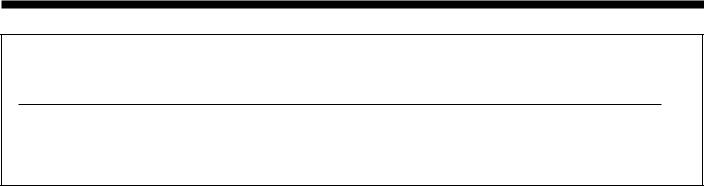
3 BOILER WATER CONNECTIONS. Open vented systems.
1.This appliance is NOT suitable for use in a direct hot water system
2.If the boiler is to be used on a sealed system an overheat thermostat kit is available and must be installed, in accordance with the instructions supplied with the kit.
3.If the boiler is to be used for gravity domestic hot water supply then cut off the spun ends of the gravity flow and return pipes and fit a 22 mm to 28 mm copper connection at the boiler gravity flow and return connections in order to run the gravity circuits in 28 mm pipe.
For Sealed System applications (fully pumped) refer to the
Overheat Thermostat Kit instructions
Ensure that the pipes are 50 mm long - measured from the top of the boiler casing if capillary fittings are used - or 35mm long if compression fittings are used.
Boiler casing
Controls pod door
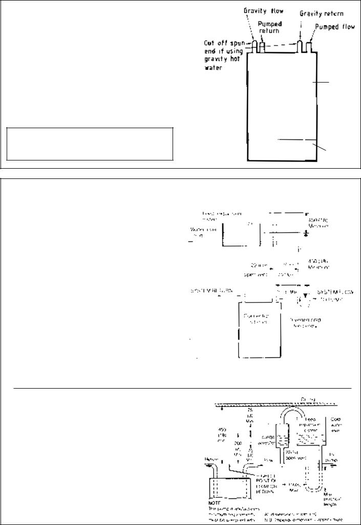
4 OPEN VENT SYSTEM REQUIREMENTS. Fully pumped.
The system should be vented directly off the boiler flow pipe, as close to the boiler as possible. The cold feed entry should be inverted and MUST be positioned between the pump and the vent, and not more than 150 mm (6 in.) away from the vent connection. Note: Alternatively, the redundant gravity flow and return connections may be used for feed and vent if a close coupled feed and vent system is not desired
There should be a minimum height - 450 mm (18 in.) of open vent above cistern water level. If this is impossible refer below.
The vertical distance between the highest point of the system and the feed/expansion cistern water level MUST not be less
than 450 mm (18 in.). The pump MUST be fitted on the flow side of the boiler.
A suitable pump is a domestic circulator capable of providing an 11°C (20°F) temperature differential (e.g. Grundfos UPS 15 /50 or equivalent). The vertical distance between the pump and feed / expansion cistern MUST comply with the pump manufacturer's minimum requirements to avoid cavitation. Should these conditions not apply, either lower the pump position or raise the cistern above the minimum requirement specified by Caradon Ideal Ltd. Note: A cold water feed path must be available back to the boiler, when all automatic valves are in the closed position (refer BS.6798) and when close coupled the feed must not be in a vertical leg.
All dimensions in mm. (in.)
All dimensions in mm. (in.)
LOW HEAD INSTALLATIONS |
MINIMUM REQUIREMENT |
The Ideal Classic range of boilers can be installed in low head situations by fitting a 'surge arrester' in the expansion pipe - as shown. The following conditions MUST be observed;
1.The surge arrester must be at least 42 mm in diameter x 150 mm long, thus ensuring a MINIMUM air gap and a
MINIMUM depth of water below the static water level (cold ) of
75 mm.
2.The static water level (cold) must be at least 200 mm above the top of the horizontal flow pipe, fitted as shown. The vent connection MUST NOT be made immediately off the top of the boiler, as venting is made less efficient.
3.The maximum practical length of 15 mm cold feed pipe should be used in order to reduce the effective volume of system water expanding into the feed / expansion cistern
7
INSTALLATION |
SYSTEM DESIGN - BOILER DIMENSIONS & CLEARANCES |
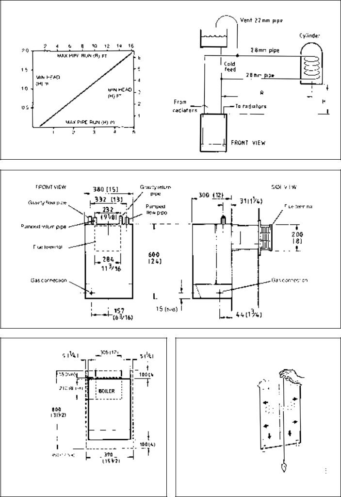
5 REQUIREMENTS FOR CORRECT GRAVITY HOT WATER PERFORMANCE
NOTE: Gravity horizontal pipes should be ABOVE ceiling level and as SHORT as possible. A MINIMUM inclination of 25 mm per 3 m run (1 in per 10 ft.) is required to avoid air locks. If these conditions cannot be met, pumped primaries MUST be used.
The above graph assumes 8 elbows in the gravity circuit. For each elbow in excess of 8, (R) must be reduced by 300 mm (12 in.) or
(H) increased by 100 mm (4 in.)
6 BOILER DIMENSIONS / SERVICES |
All dimensions in mm (in.) |
1
7 CLEARANCES & TERMINAL OPENING
Front clearance from the front of the boiler casing. These are the minimum clearances
needed to allow
access to service the boiler, but additional space may be needed for installation, depending on site conditions. Note: If using the sealed system module, refer to the instructions packed with the module for the necessary clearances.
8WALL MOUNTING TEMPLATE
1.Tape the template to the wall in the selected position. Ensure squareness by use of a plumbline - as shown.
2.Mark out the position of the 3 wallplate screws, choosing 1 from each group of 3 holes. Also mark the position of the hole for the duct, the jacking plate screw and the top cover plate screws.
3.Drill the three holes, 8 mm (5/16 in.), and insert the 3 plastic plugs. Also drill the jacking plate screw and the top cover plate screw holes and insert the plastic
plugs. 4. Remove the template from the wall.
8
 Loading...