


 Loading...
IDEAL INDUSTRIES, INC.
TECHNICAL MANUAL
MODEL: 61-700
MODEL: 61-701
MODEL: 61-702
MODEL: 61-704
The Service Information provides the following information:
•Precautions and safety information
•Specifications
•Performance test procedure
•Calibration and calibration adjustment procedure
•Basic maintenance (replacing the battery)
Form number: TM61700-1-2-4
Revision: 4. Date: Sept 2004
Form number TM61700-1-2-4 |
Rev 4 September 2004 |

TABLE OF CONTENTS |
|
Title |
Page |
|
|
Introduction |
1 |
Precautions and Safety Information |
1 |
Symbol Table |
1 |
Safety Information |
2 |
Indicator Functions |
2 |
Certifications and compliance |
2 |
Specifications |
3 |
General Specification |
3 |
Voltage Specifications |
4 |
Current Specifications |
4 |
|
|
Resistance Specifications |
4 |
Frequency Specification |
4 |
Capacitance Specifications |
4 |
Diode / Continuity Specifications |
4 |
Performance Verification |
5/6 |
|
|
Calibration |
6/7 |
Calibration Reference Points |
8 |
Replacing the Battery |
9 |
Form number TM61700-1-2-4 |
Rev 4 September 2004 |
Page 1
Introduction
 Warning
To avoid shock or injury, do not perform the verification tests or calibration procedures described in this manual unless you are qualified to do so.
The information provided in this document is for the use of qualified personnel only.
 Caution
The 61-700 series contains parts that can be damaged by static discharge. Follow the standard practices for handling static sensitive devices.
For additional information about IDEAL INDUSTRIES, INC. and its products, and services, visit IDEAL INDUSTRIES, INC. web site at: www.idealindustries.com
Precautions and Safety Information
Use the meter only as described in the Users Manual. If you do not do so, the protection provided by the meter may be impaired. Read the “Safety Information” page before servicing this product. In this manual, a Warning identifies conditions and actions that pose hazard (s) to the user; a Caution identifies conditions and actions that may damage the meter or the test instruments.
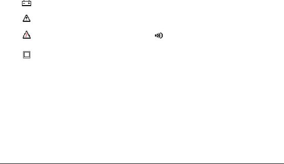
The Symbols
The symbols used on the Meter and in this manual are explained in Table A.
Table A Symbols
Symbol |
Description |
Symbol |
Indicator Lights |
|
Battery |
HI-V |
High Voltage Indicator |
|
>30 V indicator is on |
||
|
|
|
|
|
Cautionary or important |
NCV |
Non-Contact indicator |
|
information in manual |
||
|
|
|
|
|
DangerRisk of electrical |
|
Continuity indicator |
|
shock |
|
|
|
|
|
|
|
Double InsulationProtection |
CP |
Clean power indicator |
|
On if power is Clean |
||
|
Class II |
||
|
|
Off if power has > 5% THD |
|
|
|
|
|
CAT III |
IEC Over-voltage Category III |
|
|
Form number TM61700-1-2-4 |
Rev 4 September 2004 |

Page 2
SAFETY
Review the following safety precautions to avoid injury and prevent damage to this product or any products connected to it. To avoid potential hazards, use the product only as specified.
 CAUTION.
These statements identify conditions or practices that could result in damage to the equipment or other property.
 WARNING.
These statements identify conditions or practices that could result in personal injury or loss of life.
Specific precautions:
Do not operate without covers. To avoid personal injury, do not apply any voltage or current to the product without the covers in place.
Electric overload. Never apply a voltage to a connector on the product that is outside the range specified for that connector.
Avoid electric shock. To avoid injury or loss of life, do not connect or disconnect probes or test leads while they are connected to a voltage source.
Do not operate in wet/damp conditions. To avoid electric shock, do not operate this product in wet or damp conditions.
Indicator Functions:
•Hi-V: In ACV, DCV, Resistance, and Continuity/Diode test, the end user will get an audible warning and the Hi-V light will blink if there is Voltage Greater that 30V present at the input terminals.
o In addition to the LED and audible beep, the 61-702 and 61-704 has a tactile vibration when voltage is present.
•NCV: When the NCV button is pressed, the analog to digital circuit is turned off and the NCV circuit is activated. Sensing for the NCV is at the tip of the Clamp Jaw or by the Red Test Lead in the red (+) input terminal. Follow the operation instructions giving in the operator’s manual for proper use of this function. The NCV function is on Ideal Models 61-701,61-702, and 61-704.
•CP: When the 60Hz AC power is clean, with less than 5% Total Harmonics Distortion (THD) on AC voltage, the green CP light will be energized. If there is greater that 5% THD on the line, the green CP light will be de-energized.
Certifications and compliances
Safety |
Designed to IEC 1010-1, UL3111-1 and CSA specifications |
|
|
1000V DC Category III {61-702, 61-704} |
|
Input rating |
600V DC Category III {61-700, 61-701} |
|
750V AC Category III {61-702, 61-704} |
||
|
||
|
600V AC Category III {61-700, 61-701} |
|
|
CAT III: Distribution level mains, fixed installation. |
|
Over voltage category |
CAT II: Local level mains, appliances, and portable equipment. |
|
CAT I: Signal level, special equipment or parts of |
||
|
||
|
equipment, telecommunication, electronics. |
Form number TM61700-1-2-4 |
Rev 4 September 2004 |
Loading...