


61-076
Vol-Con®Voltage/
Continuity Tester (61-076)
Vol-Test™ Voltage Tester
(61-065)
Instruction Manual
WARNING
Read First: Safety Information
Use the tester only as specified in this manual;
otherwise, the protection provided by the tester
may be impaired.
Warning
To avoid possible electric shock or personal
injury, follow these instructions:
• Do not use tester if it is damaged. Visually
inspect tester to ensure case is not cracked.
• Inspect and replace leads if insulation is damaged, metal is exposed, or probes are cracked.
• Do not use tester if it operates abnormally as
protection maybe impaired.
• Do not use during electrical storms or in wet
weather.
• Do not use around explosive gas, dust, or
vapor.
• Do not apply more than the rated voltage to
the tester.
• Always operate this solenoid-type tester
within the specified duty cycle on the front of
the tester.
• Do not use without batteries and caps
properly installed. (61-076)
• Remove test leads prior to removing battery
caps. (61-076)
Caution
To protect yourself, think "Safety First":
• Voltages exceeding 30VAC or 60VDC pose a
shock hazard so use caution.
• Never ground yourself when taking electrical
measurements.
• Use appropriate personal protective equipment such as safety glasses, face shields,
insulating gloves, insulating boots, and/or
insulating mats.
• Before each use:
• Perform a continuity test by touching the
probe tips together, the continuity LED
should light. This test verifies the functionality of the batteries and test leads.
(61-076)
• Verify tester operation by measuring a
known voltage. Apply tester to circuit under
test. And, then test on the known live voltage again to ensure proper operation.
• Connect the black common lead to
ground before applying the red test lead
to voltage. Disconnect the red test lead
from the voltage first.
• Always work with a partner.
• When using the probes, keep fingers as far
behind the probe tips as possible.
Features:
• Vibration Mode with indicator movement
• Auto-Switching Voltage/Continuity
Technology (61-076)
• Independent solenoid and electronic circuitry
design provides back-up voltage indication
for added safety
• Low Impedance
• Replaceable Test Leads
• Shielded probe tips
• Ultrasonically welded and o-ring sealed for
added durability
• Indicates:
• 100-600V AC/DC (61-065)
• 5-600V AC/DC (61-076)
#61-076
#61-065
2
ND 3522-5 Vol-Con Instruct 3/25/08 4:04 PM Page 1
3
VOL-CON
®
TESTER
CATALOG NO. 61-076
NEGATIVE SIDE GLOWS ON D.C.
DUTY CYCLE ON:OFF RATIO
240 V. OR LESS 1:7
GREATER THAN 240 V. 1:40
15 SECONDS MAX. ON
AC
BOTH
5 TO 600 V.
+ DC
CONTINUITY
- DC
600 V.
100 TO
120
120
240
480
600
600
BLK
RED
240
DO NOT USE OVER 600 V.
PERFORM LEAD TEST
BEFORE USING TESTER
IDEAL INDUSTRIES, INC.
Sycamore, Illinois, U.S.A.
D.C.
A.C.
ND 2851-3
Cat III - 600V
Listed
Voltage Testers
122X
Neon Bulb
100-600V AC/DC
LEDs (61-076)
5-600V AC/DC
Continuity
Indicator
120-600V AC/DC
4
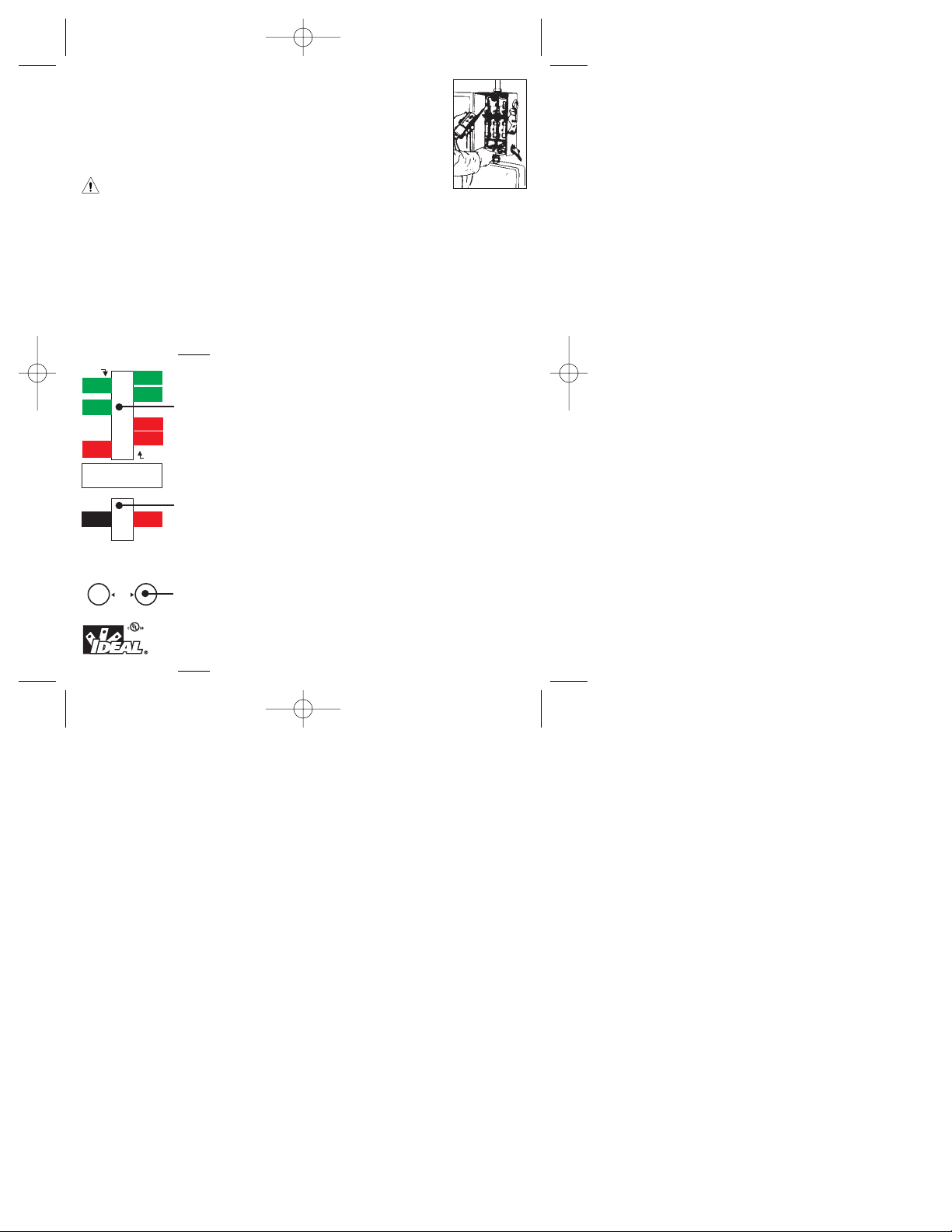
To Measure AC/DC Voltage:
• Ensure that the plug for the test leads is fully
seated into the banana jacks.
• Connect the tester in parallel with the load or
circuit.
• The tester indicates the voltage type, DC
polarity, and the voltage level.
Warning
Do not exceed duty cycle specified on tester.
To Test for Continuity (61-076):
• Ensure that the plug for the test leads is fully
seated into the banana jacks.
• Test for continuity by connecting the tester to
the de-energized circuit.
• If circuit has <500kΩ, the Continuity LED
lights.
• Reversing prods on the circuit under test
verifies continuity versus low voltage +DC.
Applications:
• Locating Blown Fuses
With power off (61-076):
Place tester across the
suspected fuse to perform
continuity check. If
continuity LEDlights, the
fuse is good. If not, the
fuse is defective.
With power on: Place tester across the
“source” side of one fuse and the load side of
an adjoining fuse. If no or low voltage is indicated, the fuse next to the load side prod is
blown. If line voltage is indicated, the fuse
next to the load side prod is OK. Repeat the
same test with the prods on the opposite side
of the same two fuses to check the other fuse.
• Finding Grounded Side of Line
(neutral)
Hold one test prod to the ground and touch
the other test prod to each of the line terminals
until one is found that does not give a voltage
indication. This is the grounded side of the
line.
The continuity LED should also light. (61-076)
• Checking Continuity of Cords, Motors,
Appliances, etc. (61-076)
Remove power source and place tester across
circuit to be tested. Continuity LEDlights if
resistance is less than 500kΩ.
• Locating Excessive Leakage to Ground
(61-076)
Place tester across the neutral terminal and the
ground. The single continuity LED should indicate neutral and ground are connected. If both
LEDs light, there is > 5VAC (N-G) indicating a
high resistance leakage to ground.
ND 3522-5 Vol-Con Instruct 3/25/08 4:04 PM Page 3

Battery Replacement (61-076):
• Replace batteries when touching the leads
together no longer lights the continuity LED.
• Remove test leads from tester.
• Carefully, pry the two battery caps from the
bottom of the case using a screwdriver.
• Replace the batteries.
• Snap the battery caps back in place ensuring
the cap is flush with the bottom of the case.
Accessories:
• 61-070 Standard test leads
• 61-072 Resistor-fused test leads
• C-90 Soft-sided carrying case
• 61-010 Leather case
Maintenance:
• Clean the case with a damp cloth and mild
detergent. Do not use abrasives or solvents.
Service, and Replacement Parts:
For replacement parts or to inquire about service
information contact Technical Support:
1-877-201-9005 or visit our website
www.testersandmeters.com.
Warranty Statement:
This tester is warranted to the original purchaser against
defects in material and workmanship for two years from
the date of purchase. During this warranty period, IDEAL
INDUSTRIES, INC. will, at its option, replace or repair
the defective unit, subject to verification of the defect or
malfunction.
This warranty does not cover fuses, batteries or damage
from abuse, neglect, accident, unauthorized repair, alteration, or unreasonable use of the instrument.
Any implied warranties arising out of the sale of an
IDEAL product, including but not limited to implied warranties of merchantability and fitness for a particular purpose, are limited to the above. The manufacturer shall
not be liable for loss of use of the instrument or other
incidental or consequential damages, expenses, or economic loss, or for any claim or claims for such damage,
expenses or economic loss.
State laws vary, so the above limitations or exclusions
may not apply to you. This warranty gives you specific
legal rights, and you may also have other rights which
vary from state to state.
6
5
Specifications:
VAC Ranges: 120V, 240V, 480V, 600V AC.
VDC Ranges: 120V, 240V, 600V DC
Volts Accuracy: Relative indication only
Continuity: LED lights at <500kΩ
Response time of 100ms.
Frequency: Operates at 25-60 Hz
Overload 1000VDC/750VAC rms.
protection:
Operating 32°F to 122°F
Environment: (0 to 50°C)(<70% humidity)
Storage Temp.: -4°F to 140°F (-20 to 60°C)
(<80% humidity)
Battery: (4) 1.5V (61-201, IEC LR44)
Battery Life: 200 hours typical.
Accessories Test Leads, (4) Batteries,
included: Operating Manual
Dimensions: 7.2"H x 2.4"W x 1.5"D
[183H x 61W x 38D]mm
Weight: 8.0 oz (227g)
Safety: UL-61010, CAT III-600V
Double Insulation
Instrument has been evaluated and complies
with insulation category III (overvoltage
category III). Pollution degree 2 in accordance
with IEC-644. Indoor use.
ND 3522-5 Vol-Con Instruct 3/25/08 4:04 PM Page 5
• Quite los cables de prueba para quitar la tapa
de las pilas. (61-076)
Precaución
Para protegerse, piense en la "Seguridad ante
todo":
• Los voltajes que superen 30 VCA o 60 VCA
presentan un peligro de descarga, por lo que
debe tener cuidado.
• No se conecte nunca a tierra cuando tome
medidas eléctricas.
• Use equipos de protección personal tales
como gafas de seguridad, máscaras, guantes
aislantes, botas aislantes y esteras aislantes.
• Use el método de prueba de 3 pasos antes de
usarlo:
• Realice una prueba de continuidad poniendo en contacto las puntas de la sonda entre
sí, la luz LED de continuidad debe encenderse. Esta prueba verifica la funcionalidad
de las pilas y cables de prueba.
(61-076)
• Verifique la operación del probador midiendo un voltaje conocido. Aplique el
probador al circuito que se esté probando.
Y después pruebe el voltaje conectado
conocido para asegurar una operación
apropiada.
• Conecte el cable común negro a tierra antes
de aplicar el cable de prueba rojo al voltaje.
Desconecte primero el cable de prueba rojo
del voltaje.
• Trabaje siempre con un compañero.
• Al usar las sondas, mantenga los dedos lo más
detrás posible de las puntas de las sondas.
Características:
• Modalidad de vibración con movimiento de
indicador
• Tecnología de voltaje/continuidad de conmutación automática (61-076)
• Diseño de solenoides y circuitos electrónicos
independientes que proporciona una indicación de voltaje de reserva para mayor
seguridad.
#61-076
#61-065
Probador de voltaje/continuidad Vol-Con® (61-076)
Voltímetro Vol-Test®(61-065)
Manual de instrucciones
ADVERTENCIA
Lea primero: Información de seguri-
dad
Use el probador sólo según se especifica en este
manual; de lo contrario, se puede deteriorar la protección proporcionada por el probador.
Advertencia
Siga estas instrucciones para evitar una posible
descarga eléctrica o lesiones personales:
• No use el instrumento si está dañado.
Inspecciónelo visualmente para asegurarse de
que la carcasa no esté dañada.
• Inspeccione y reemplace los cables si el aislamiento está dañado, hay piezas metálicas
expuestas o las sondas están fisuradas.
• No use el probador si funciona de forma anormal, ya que la protección puede haber disminuido.
• No lo use durante tormentas eléctricas o cuando llueva.
• No lo use con gases, polvo o vapores explosivos.
• No aplique más del voltaje nominal al probador.
• Opere siempre este instrumento de tipo de solenoide con el ciclo de trabajo específicado en el
frente del mismo.
• No lo use sin pilas y sin la tapa bien instalada.
(61-076)
8
7
ND 3522-5 Vol-Con Instruct 3/25/08 4:04 PM Page 7
 Loading...