IDEAL 61-702 User Manual

#61-702 #61-704
700 Series
200 Amp Clamp Meters
1
2
3
6
5 |
7 |
|
4
8
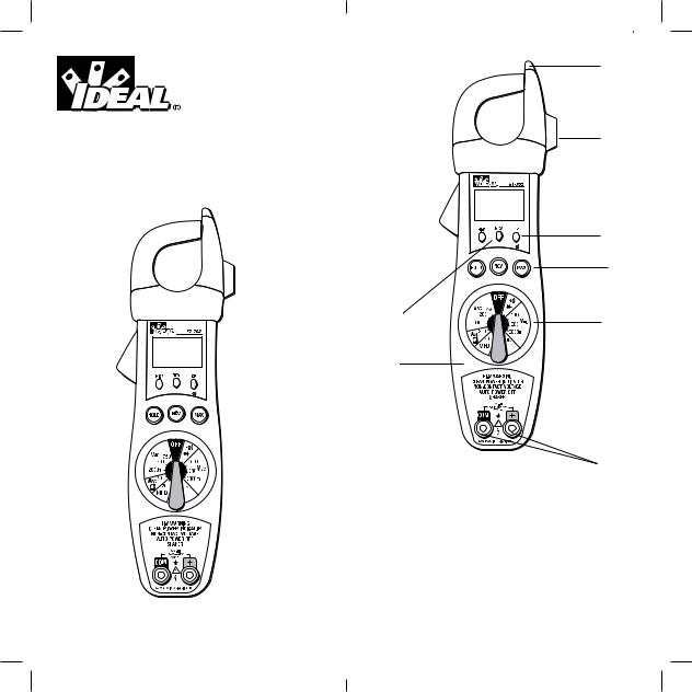
1.Non-contact voltage (NCV) (#61-702)
With the NCV tab on the tip of the clamp close to an AC voltage, press the NCV button. The NCV LED will light and the beeper will beep. The closer the NCV tab is to AC voltage, the louder the beep.
To differentiate between hot and neutral in an outlet, insert the NCV tab into each slot in the outlet. The beeper will be much louder on the hot side of the outlet than the neutral.
2

The test lead can also be used to differentiate between the hot and neutral. Insert the rod test lead into the + port and snap it into the test probe holder. Press the NCV button and insert the probe into each slot of the outlet. The beeper will only beep on the hot side of the outlet.
2.Test probe holder
Use the single test probe holder to make voltage testing easy.
3.Indicator lights
HI-V High voltage indicator
In any VAC/VDC range when a voltage greater than 30V is touched, the beeper will beep, and the red Hi-V LED will blink.
In addition to the LED and beeper, the meter will shake when connected to high voltage. Even if the LED can’t be seen, or the beeper can’t be heard the shake can be felt.
NCV |
Non-contact voltage indicator |
|
Continuity indicator |
CP |
Clean power indicator |
When the 60Hz AC power is clean, the green LED will be on. If the meter is connected to AC power, and the green LED is not on, the circuit has more than 5% (±2%) total harmonic distortion (nominal). Investigation with specialized equipment may be necessary. Sensitivity: 20VAC on 200VAC range; 90V on 750VAC range.
4.Hold button (#61-702)
Press hold button during measurement to capture the value. To clear the held value, press the hold button again, or press the reset button.
5.NCV button
Press the NCV button to test for non-contact voltage.
6.Backlight (#61-704)
Backlight auto-off approximately 60 sec.
3
7.Max button
Press Max prior to a measurement to capture the maximum reading displayed during the measurement. To clear the max value, press the max button again, or press the reset button.
8.Rotary switch
Turn the rotary switch to the appropriate function and range for the measurement.
9.COM port and + port
Plug the black lead into the com port and the red lead into the + port for VAC, VDC, Frequency, Resistance, and Capacitance measurements and Diode and Continuity checks.
WARNING!
1.DO NOT UNDER ANY CIRCUMSTANCES EXCEED THESE RATINGS:
•Voltage is not to exceed 750VAC or 1000VDC
•Resistance, function is not to be performed on circuits capable of delivering greater than 600 Volts.
•Frequency, Capacitance and Continuity functions
are not to be performed on circuits capable of delivering greater than 500 Volts.
2.To avoid electrical shock hazards and/or damage to the meter:
•Test NCV function on known live wire before using.
•Do not exceed the voltage ratings for the meter. Use caution when measuring voltage.
•Do not use during electrical storms. AC power sources with inductive loads or electrical storms may result in high voltage. High energy transients can damage meter and present a dangerous shock hazard.
•Turn off power to the circuit or device being measured before taking resistance and capacitance measurements. Fully discharge all capacitors before measuring.
3.Ensure meter is in proper working order before using. Visually inspect meter for damage. Performing a continuity check can verify proper operation. If the meter reading goes from overload to zero, this typically means the meter is in proper working order.
4
 Loading...