


INSTRUCTION MANUAL
VHF TRANSCEIVER
iV80
iV80E
This device complies with Part 15 of the FCC Rules. Operation is subject to the following two conditions: (1) this device may not cause harmful interference, and (2) this device must accept any interference received, including interference that may cause undesired operation.
WARNING: MODIFICATION OF THIS DEVICE TO RECEIVE CELLULAR RADIOTELEPHONE SERVICE SIGNALS IS PROHIBITED UNDER FCC RULES AND FEDERAL LAW.

FOREWORD
Thank you for purchasing this fine Icom product. The IC-V80/ V80E vhf transceiver is designed and build with Icom’s superior technology and craftsmanship. With proper care, this product should provide you with years of trouble-free operation.
We want to take a couple of moments of your time to thank you for making your IC-V80/V80E your radio of choice, and hope you agree with Icom’s philosophy of “technology first.” Many hours of research and development went into the design of your IC-V80/V80E.
EXPLICIT DEFINITIONS
WORD |
DEFINITION |
R DANGER! Personal death, serious injury or an explosion may occur.
RWARNING! Personal injury, fire hazard or electric shock may occur.
CAUTION Equipment damage may occur. |
||
|
|
|
NOTE |
Recommended for optimum use. No risk |
|
of personal injury, fire or electric shock. |
||
|
||
FEATURES
D u s t - p r o t e c t i o n / S p l a s h - r e s i s t a n t construction (IP54*)
*Only when the battery pack/case, antenna and jack cover are attached.
Built in VOX circuit enabling the VOX operation* (voice operated transmission)
*To use the VOX operation, an optional headset and a plug adapter cable are additionally required.
IMPORTANT
READ ALL INSTRUCTIONS carefully and completely before using the transceiver.
SAVE THIS INSTRUCTION MANUAL— This instruction manual contains important operating instructions for the IC-V80/V80E.

PRECAUTIONS
RWARNING RF EXPOSURE! This device emits
Radio Frequency (RF) energy. Caution should be observed when operating this device. If you have any questions regarding RF exposure and safety standards, please refer to the Federal Communications Commission Office of Engineering and Technology’s report on Evaluating Compliance with FCC Guidelines for Human Radio Frequency Electromagnetic Fields (OET Bulletin 65)
RWARNING! NEVER hold the transceiver so that the antenna is very close to, or touching exposed parts of the body, especially the face or eyes, while transmitting. The transceiver will perform best if the microphone is 5 to 10 cm (2 to 4 inches) away from the lips and the transceiver is vertical.
RWARNING! NEVER operate the transceiver with a headset or other audio accessories at high volume levels. Hearing experts advise against continuous high volume operation. If you experience a ringing in your ears, reduce the volume level or discontinue use.
RWARNING! NEVER operate the transceiver while driving a vehicle. Safe driving requires your full attention— anything less may result in an accident.
NEVER connect the transceiver to a power source using reverse polarity. This will ruin the transceiver.
DO NOT operate the transceiver near unshielded electrical blasting caps or in an explosive atmosphere.
DO NOT push [PTT] unless you actually intend to transmit.
BE CAREFUL! The transceiver will become hot when operating it continuously for long periods.
DO NOT use or place the transceiver in direct sunlight or in areas with temperatures below –20°C (–4˚F) or above +60°C (+140˚F).
Place the unit in a secure place to avoid inadvertent use by children.
DO NOT use harsh solvents such as benzene or alcohol to clean the transceiver, because they can damage the transceiver’s surfaces.
ii

PRECAUTIONS
KEEP the transceiver away from heavy rain, and never immerse in the water. The transceiver meets IP54* requirements for dust-protection and splash resistance. However, once the transceiver has been dropped, dust-protection and splash resistance cannot be guaranteed because of possible damage to the transceiver’s case or the waterproof seal.
*Only when the battery pack/case, antenna and jack cover are attached.
NEVER operate or touch the transceiver with wet hands. This may result in an electric shock or may damage the transceiver.
Even when the transceiver power is OFF, a slight current still flows in the circuits. Remove the battery pack or batteries from the transceiver when not using it for a long time. Otherwise, the installed battery pack or batteries will become exhausted, and will need to be recharged or replaced.
Approved Icom optional equipment is designed for optimal performance when used with an Icom transceiver.
Icom is not responsible for the destruction or damage to an Icom transceiver in the event the Icom transceiver is used with equipment that is not manufactured or approved by Icom.
iii
FCC INFORMATION
• FOR CLASS B UNINTENTIONAL RADIATORS:
This equipment has been tested and found to comply with the limits for a Class B digital device, pursuant to part 15 of the FCC Rules. These limits are designed to provide reasonable protection against harmful interference in a residential installation. This equipment generates, uses and can radiate radio frequency energy and, if not installed and used in accordance with the instructions, may cause harmful interference to radio communications. However, there is no guarantee that interference will not occur in a particular installation. If this equipment does cause harmful interference to radio or television reception, which can be determined by turning the equipment off and on, the user is encouraged to try to correct the interference by one or more of the following measures:
•Reorient or relocate the receiving antenna.
•Increase the separation between the equipment and receiver.
•Connect the equipment into an outlet on a circuit different from that to which the receiver is connected.
•Consult the dealer or an experienced radio/TV technician for help.
CAUTION: Changes or modifications to this device, not expressly approved by Icom Inc., could void your authority to operate this device under FCC regulations.
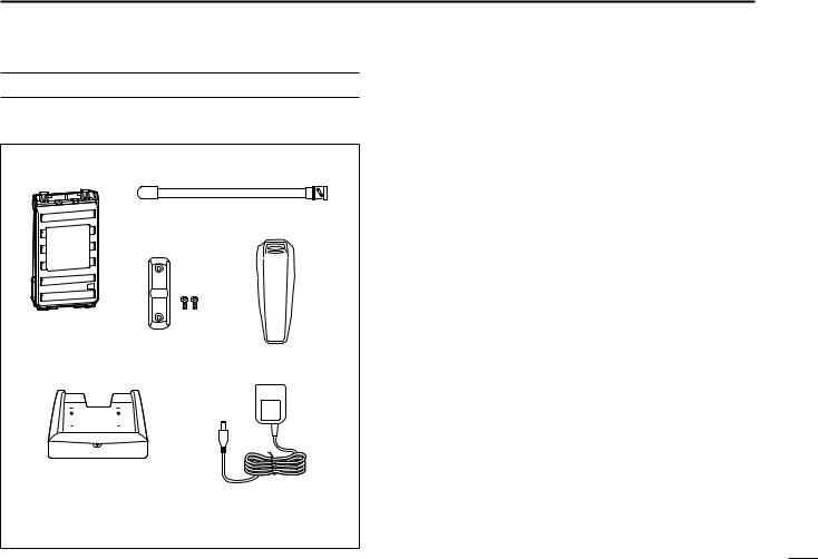
SUPPLIED ACCESSORIES
The following accessories are supplied with the transceiver.
Battery pack* |
Antenna |
Jack cover |
Belt clip* |
(with screws) |
|
Battery charger* |
|
AC adapter* |
|||||||||||
|
|
|
|
|
|
|
|
|
|
|
|
|
|
|
|
|
|
|
|
|
|
|
|
|
|
|
|
|
|
|
|
|
|
|
|
|
|
|
|
|
|
|
|
|
|
|
|
|
|
|
|
|
|
|
|
|
|
|
|
|
|
|
|
|
|
|
|
|
|
|
|
|
|
|
|
|
|
|
|
|
|
|
|
*Not supplied, or the shape is different, depending on the version.
Icom, Icom Inc. and the Icom logo are registered trademarks of Icom Incorporated (Japan) in Japan, the United States, the United
Kingdom, Germany, France, Spain, Russia and/or other countries.
Microsoft, Windows and Windows Vista are registered trademarks of Microsoft Corporation in the United States and/or other countries.
1
2
3
4
5
6
7
8
9
10
11
12
13
14
15
16
17
18
19
iv

TABLE OF CONTENTS
FOREWORD...................................................................................... |
i |
FEATURES........................................................................................ |
i |
EXPLICIT DEFINITIONS................................................................... |
i |
IMPORTANT....................................................................................... |
i |
PRECAUTIONS............................................................................ |
ii–iii |
FCC INFORMATION........................................................................ |
iii |
SUPPLIED ACCESSORIES............................................................ |
iv |
TABLE OF CONTENTS............................................................... |
v–vi |
1 ACCESSORIES............................................................ |
1–2 |
■ Antenna.................................................................................... |
1 |
■ Belt clip..................................................................................... |
1 |
■ Battery pack/case..................................................................... |
2 |
■ Jack cover................................................................................ |
2 |
2 |
PANEL DESCRIPTION................................................ |
3–7 |
. |
■. Front, top and side panels........................................................ |
3 |
|
■ Function display....................................................................... |
6 |
3 |
BATTERY CHARGING............................................... |
8–13 |
|
■ Caution (for the BP-264 Ni-MH battery).................................... |
8 |
|
■ Caution (for the BP-265 Li-Ion battery).................................... |
9 |
|
■ Battery chargers..................................................................... |
11 |
|
■ Battery case (BP-263)............................................................... |
13 |
|
■ Battery information................................................................. |
13 |
4 |
BASIC OPERATION................................................ |
14–19 |
|
■ Power ON............................................................................... |
14 |
|
■ Adjusting the volume level...................................................... |
14 |
|
■ Adjusting the squelch level..................................................... |
14 |
■ Monitor function...................................................................... |
14 |
■ Mode selection....................................................................... |
15 |
■ Operating mode selection...................................................... |
16 |
■ Setting a tuning step............................................................... |
16 |
■ Setting a frequency................................................................ |
16 |
■ Receiving................................................................................ |
17 |
■ Transmitting............................................................................ |
17 |
■ Key lock function.................................................................... |
18 |
■ [VOL] function assignment..................................................... |
18 |
■ Weather channel operation (U.S.A. version only)................... |
19 |
5 REPEATER AND DUPLEX OPERATION................ |
20–23 |
■ Repeater operation................................................................. |
20 |
■ Duplex operation.................................................................... |
21 |
■ Subaudible tones.................................................................... |
22 |
■ Lockout function..................................................................... |
23 |
■ Auto repeater function (U.S.A. version only) .......................... |
23 |
6 MEMORY/CALL OPERATION................................. |
24–28 |
■ General description................................................................ |
24 |
■ Selecting a memory channel.................................................. |
24 |
■ Selecting the Call channel...................................................... |
24 |
■ Channel programming............................................................ |
25 |
■ Copying memory/Call contents.............................................. |
26 |
■ Clearing memory contents............................................................. |
27 |
■ Display type............................................................................ |
27 |
■ Programming a channel name.................................................. |
28 |

TABLE OF CONTENTS
7 |
SCAN OPERATION................................................. |
29–31 |
|
■ Scan types.............................................................................. |
29 |
. |
■. Programmed scan ................................................................. |
29 |
|
■ Memory Scan......................................................................... |
30 |
|
■ Setting skip channels............................................................. |
30 |
|
■ Scan resume setting............................................................... |
30 |
|
■ Priority watch.......................................................................... |
31 |
8 TONE SQUELCH AND POCKET BEEP.................. |
32–34 |
■ Tone/DTCS squelch and pocket beep.................................... |
32 |
■ Tone scan............................................................................... |
34 |
9 DTMF MEMORY....................................................... |
35–37 |
■ Programming a DTMF code sequence................................... |
35 |
■ Transmitting a DTMF code sequence..................................... |
36 |
■ Confirming a DTMF memory.................................................. |
37 |
■ Setting DTMF transfer speed................................................. |
37 |
10 SET MODES............................................................ |
38–47 |
■ Set mode programming.......................................................... |
38 |
■ Set mode items...................................................................... |
39 |
■ Initial Set mode programming................................................... |
43 |
■ Initial Set mode items............................................................. |
44 |
11 CLONING....................................................................... |
48 |
■ Cloning operation................................................................... |
48 |
12 RESETTING................................................................... |
49 |
■ Resetting................................................................................ |
49 |
13 TROUBLE....... SHOOTING.......................................................... |
50 |
14 OPTIONS................................................................. |
51–53 |
■ VOX function........................................................................... |
52 |
15 SPECIFICATIONS.......................................................... |
54 |
16 CE............................................................................. |
55–56 |
1
2
3
4
5
6
7
8
9
10
11
12
13
14
15
16
17
18
19
vi
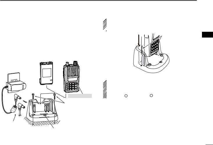
 1 ACCESSORIES
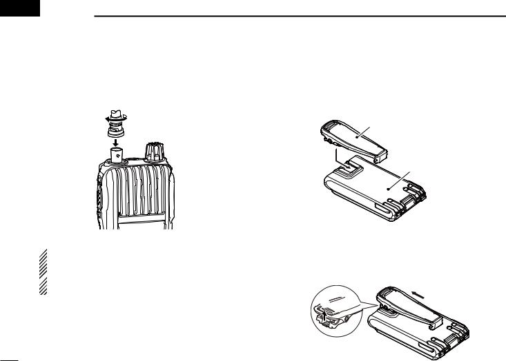
■ Antenna
Insert the antenna into the antenna connector and twist the antenna to lock it in place.
■ Belt clip
To attach the belt clip:
Slide the belt clip in the direction of the arrow until the belt clip locks in place, and makes a ‘click’ sound.
Belt clip
Battery pack/case
 CAUTION:
• NEVER HOLD just the antenna when carrying the trans-
ceiver.
 • Transmitting without an antenna will damage the transceiver.
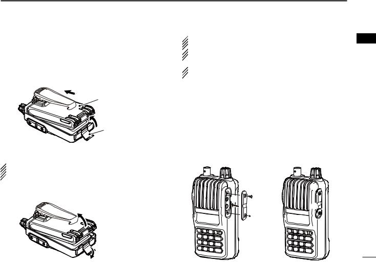
To detach the belt clip:
q Remove the battery pack/case from the transceiver, if it is attached. (p. 2).
w Lift the tab up (q), and slide the belt clip in the direction of the arrow (w).
w
q
■ Battery pack/case
To attach the battery pack/case:
q Fit the battery pack/case in the direction of the arrow (q), then close.
w Hook the latch until it makes a ‘click’ sound (w).
 q
q
Battery pack/case
w
Latch
To remove the battery pack/case:
 Be careful! The latch is tightly locked, so use caution
when releasing it. DO NOT use your finger nail. Use the  edge of a coin or screwdriver tip to carefully release it.
Unhook the latch (e), and lift up the battery pack/case in the direction of the arrow (r).
ACCESSORIES 1
 NEVER remove or attach the battery pack/case when the transceiver is wet or soiled. This may result in water or
  dust getting into the transceiver/battery pack/case, and
 may result in them being damaged.
 NOTE: Keep the battery terminals clean. It’s a good idea
  to clean the battery terminals once a week.
■ Jack cover
Attach the jack cover when optional equipment is not used.
To attach the jack cover qAttach the jack cover to
the [SP MIC] jack. wTighten the screws.
w
q
 w
w
To detach the jack cover eRemove the screws with a
phillips screwdriver.
rDetach the jack cover to connect optional equipment.
e
e  r
r
1
2
3
4
5
6
7
8
9
10
11
12
13
14
15
16
17
18
19
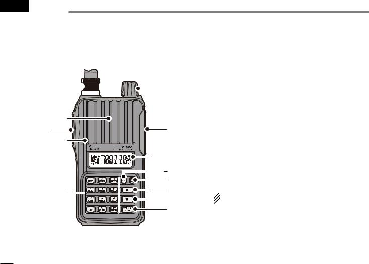
 2 PANEL DESCRIPTION
■ Front, top and side panels
w

 e
e
Speaker |
q |
Microphone |
r
Function display (p. 6)
t y
Keypad (p. 4) |
u |
|
|
|
i |
qPTT SWITCH [PTT]
Push and hold to transmit, release to receive. (p. 17)
For IC-V80E only
Push briefly, then push and hold to transmit a 1750 Hz tone burst signal. (p. 22)
wANTENNA CONNECTOR
Connect the antenna here. (p. 1) eCONTROL DIAL [VOL]
Adjust the volume level. (p. 14)
During the Set mode, or Initial Set mode, rotate to select a desired option or value. (pp. 38, 43)
rEXTERNAL SPEAKER/MICROPHONE JACKS [SP MIC]
Used to connect an optional speaker-microphone, plug adapter cable or cloning cable. The internal microphone and speaker will not function when an option is connected. See page 51 for a list of available options.
 Be sure to turn power OFF before connecting/discon-
 necting optional equipment to/from the [SP/MIC] jack. tMONITOR KEY [MONI]
Push and hold to open the squelch temporarily to monitor the operating frequency. (p. 14)
While pushing and holding this key, push [] or [] to adjust the squelch level. (p. 14)
Enters or sends the DTMF code ‘A.’ (pp. 35, 36)
yPOWER KEY [ ]
]
Push and hold for 1 sec. to turn the transceiver power ON or OFF. (p. 14)
uUP/DOWN KEYS []/[]
Push to change the operating frequency. (p. 16)
During memory mode operation, push to select a memory channel. (p. 24)
While scanning, push to change the scanning direction. (pp. 29, 30, 31, 34)
While pushing and holding [MONI], push to set the squelch level. (p. 14)
During the Set mode, or Initial Set mode, push to select a desired setting item. (pp. 38, 43)
[] enters or sends the DTMF code ‘B.’ (pp. 35, 36)
[] enters or sends the DTMF code ‘C.’ (pp. 35, 36)
iVFO/MEMORY/CALL KEY [VFO/MR/CALL]
Push to select the VFO mode, memory mode, a Call channel and a weather channel*, in sequence. (p. 15)
*Only the U.S.A. version transceivers.
After pushing [FUNC](M), push to enter the memory programming mode.
After pushing [FUNC](M), push and hold for 1 sec. to transfer a channel contents to a memory channel, or to the VFO mode. (p. 26)
Enters or sends the DTMF code ‘D.’ (pp. 35, 36)
 The functions of [VOL] and []/[] can be exchanged.
  See page 18 for details.
PANEL DESCRIPTION 2
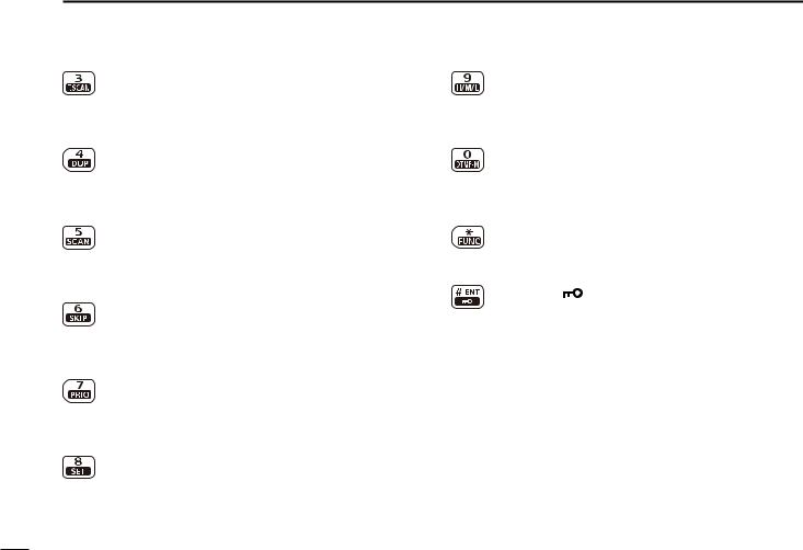
D KEYPAD
Push to input numbers for frequency input and memory channel selection.
Push to enter or send the DTMF code. (pp. 35, 36)
To activate the second function of a key, first push [FUNC](M), and then push the key.
[1] • [ TONE](1)
Numeric input and DTMF code: ‘1’
After pushing [FUNC](M), selects the Tone function. (p. 33)
[2] • [VOX](2)
Numeric input and DTMF code: ‘2’
After pushing [FUNC](M), turns the VOX function ON or OFF*. (p. 52)
*Only when an optional headset and plug adapter are connected.
1
2
3
4
5
6
7
8
9
10
11
12
13
14
15
16
17
18
19
2 PANEL DESCRIPTION
[3] • [T.SCAN](3)
Numeric input and DTMF code: ‘3’
After pushing [FUNC](M), starts a tone scan. (p. 34)
[4] • [DUP](4)
Numeric input and DTMF code: ‘4’
After pushing [FUNC](M), selects minus duplex, plus duplex, or simplex operation. (p. 21)
[5] • [SCAN](5)
Numeric input and DTMF code: ‘5’
After pushing [FUNC](M), starts a scan. (pp. 29, 30)
[6] • [SKIP](6)
Numeric input and DTMF code: ‘6’
After pushing [FUNC](M), sets or cancels the skip setting. (p. 30)
[7] • [PRIO](7)
Numeric input and DTMF code: ‘7’
After pushing [FUNC](M), starts a priority watch. (p. 31)
[8] • [SET](8)
Numeric input and DTMF code: ‘8’
After pushing [FUNC](M), enters the Set mode. (p. 38)
[9] • [H/M/L](9)
Numeric input and DTMF code: ‘9’
After pushing [FUNC](M), selects the output power between high, middle and low. (p. 17)
[0] • [DTMF-M](0)
Numeric input and DTMF code: ‘0’
After pushing [FUNC](M), enters the DTMF memory mode. (p. 35)
[M] • [FUNC](M)
DTMF code: ‘M (indication: E)’
Push to access the second function of other keys.
[# ENT] • [ ](# ENT)
DTMF code: ‘# (indication: F)’
After entering a frequency, stores the frequency. (p. 16)
Push to exit the Set mode or Initial Set mode. (pp. 38, 43)
After pushing [FUNC](M), push and hold for 1 sec. to turn the key lock function ON or OFF (p. 18)

■ Function display
qw e r |
t |
y |
!5 |
|
u |
|
i |
|
!4 |
|
|
|
o |
|
!3 |
|
|
|
|
|
!2!1!0 |
|
|
qBUSY INDICATOR
Appears when a signal is being received, or the squelch is open.
Blinks while the monitor function is ON. (p. 14)
wSIGNAL INDICATOR
Shows the strength of the received signal. (p. 17)
Weak RX Signal level Strong
While transmitting, shows the output power level. (p. 17)
|
|
|
|
|
|
|
|
|
|
|
|
|
|
|
|
|
|
|
|
|
|
|
|
|
|
|
|
|
|
|
|
|
|
|
|
|
|
|
|
|
|
Low |
Middle |
High |
|||||||||||
PANEL DESCRIPTION 2
eTONE INDICATOR
“ ” appears while the repeater tone encoder is ON. (p. 20)
“ ” appears while the tone squelch function is ON. (p. 33)
“D ” appears while the DTCS squelch function is ON. (p. 33)
“ ” appears with the “
 ” or “D ” indicator while the pocket beep function (with CTCSS or DTCS) is ON. (p. 33)
rMEMORY INDICATOR
Appears when the memory mode is selected. (pp. 15, 24) tFREQUENCY READOUT
Displays the operating frequency, memory channel, Set modes contents and a variety of other information.
• The decimal point blinks during scan.
During memory mode operation, the programmed memory name is displayed.
yBATTERY INDICATOR (p. 13)
“ ” (battery indicators) appear when the battery pack/case is attached.
“ ” appears when the battery pack must be changed, or batteries must be replaced.
1
2
3
4
5
6
7
8
9
10
11
12
13
14
15
16
17
18
19

2 PANEL DESCRIPTION
uKEY LOCK INDICATOR
Appears when the key lock function is ON. (p. 18)
iVOX INDICATOR
Appears when the VOX function is ON. (p. 52) oPOWER INDICATOR (p. 17)
“H” appears when high power is selected.
“M” appears when middle power is selected.
“L” appears when low power is selected.
!0MEMORY CHANNEL NUMBER INDICATOR
Displays the selected memory channel number. (p. 24)
“C” appears when the Call channel is selected. (p. 24)
!1AUTO POWER OFF INDICATOR
Displays when the Auto Power OFF function is ON. (p. 44)
!2DUPLEX INDICATOR (p. 21)
“+” appears when plus duplex is selected.
“–” appears when minus duplex is selected.
!3SKIP INDICATOR
Appears when the selected memory channel is set as a skip channel. (p. 30)
!4FUNCTION INDICATOR
Appears when the second function can be accessed.
!5TRANSMIT INDICATOR
Appears while transmitting. (p. 17)

■ Caution (for the BP-264 Ni-MH battery)
R DANGER! NEVER short terminals (or charging terminals) of the battery pack. Also, current may flow into nearby metal objects such as a necklace, so be careful when placing battery packs (or the transceiver) in handbags, etc.
Simply carrying with or placing near metal objects such as a necklace, etc. may cause shorting. This may damage not only the battery pack, but also the transceiver.
R DANGER! NEVER incinerate used battery packs. Internal battery gas may cause an explosion.
R DANGER! NEVER immerse the battery pack in water. If the battery pack becomes wet, be sure to wipe it dry BEFORE attaching it to the transceiver.
CAUTION: Always use the battery within the specified temperature range, –5˚C to +60˚C (+23˚F to +140˚F). Using the battery out of its specified temperature range will reduce the battery’s performance and battery life.
CAUTION: Shorter battery life could occur if the battery is left completely discharged, or in an excessive temperature environment (above +55˚C; +131˚F) for an extended period of time. If the battery must be left unused for a long time, it must be detached from the radio after charging. Keep it safely in a cool dry place at the following temperature range:
–20˚C to +45˚C |
(–4˚F to +113˚F) |
(up to a month) |
–20˚C to +35˚C |
(–4˚F to +95˚F) |
(up to six months) |
–20˚C to +25˚C |
(–4˚F to +77˚F) |
(up to a year*) |
* We recommend charging the battery pack every 6 months.
BATTERY CHARGING |
3 |
|
|
|
|
|
|
|
|||
|
|
|
|||
|
1 |
||||
Clean the battery terminals to avoid rust or misscontact. |
|||||
Keep battery terminals clean. It’s a good idea to clean bat- |
|
||||
2 |
|||||
tery terminals once a week. |
|
|
|
|
|
|
|
3 |
|||
If your Ni-MH battery pack seems to have no capacity, even |
|||||
4 |
|||||
after being charged, completely discharge it by leaving the |
|||||
power ON overnight. Then, fully charge the battery pack again. |
5 |
||||
If the battery pack still does not retain a charge (or only very lit- |
|||||
6 |
|||||
tle charge), a new battery pack must be purchased. (p. 51) |
|||||
Prior to using the transceiver for the first time, the battery |
7 |
||||
pack must be fully charged for optimum life and operation. |
|||||
8 |
|||||
• Recommended temperature range for charging: |
|
|
|||
between +10°C and +40°C (rapid charge: with BC-191) or |
9 |
||||
between 0°C and +45°C (regular charge: with BC-192) |
10 |
||||
• Use the supplied charger or optional charger (BC-191 for |
|||||
|
|
||||
rapid charging, BC-192 for regular charging) only. NEVER |
11 |
||||
use other manufacturers’ chargers. |
|
|
12 |
||
The battery pack contains a rechargeble battery. |
|
|
|||
|
|
13 |
|||
Charge the battery pack before first operating the trans- |
|||||
14 |
|||||
ceiver, or when the battery pack becomes exhausted. |
|
|
|||
If you want to prolong the battery life, the following points |
15 |
||||
should be observed: |
|
|
|||
|
|
16 |
|||
• Avoid over charging. The charging time period should be |
|||||
less than 48 hours. |
|
|
17 |
||
• Use the battery pack until it becomes almost completely |
|||||
18 |
|||||
exhausted, under normal conditions. We recommend bat- |
|||||
tery charging after transmitting becomes impossible. |
|
|
19 |
||
|
|
|
|
|
|

3 BATTERY CHARGING
■ Caution (for the BP-265 Li-Ion battery)
Misuse of Li-Ion batteries may result in the following hazards: smoke, fire, or the battery may rupture. Misuse can also cause damage to the battery or degradation of battery performance.
R DANGER! Use and charge only specified Icom battery packs with Icom radios or Icom chargers. Only Icom battery packs are tested and approved for use with Icom radios or charged with Icom chargers. Using third-party or counterfeit battery packs or chargers may cause smoke, fire, or cause the battery to burst.
D Battery caution
R DANGER! DO NOT hammer or otherwise impact the battery. Do not use the battery if it has been severely impacted or dropped, or if the battery has been subjected to heavy pressure. Battery damage may not be visible on the outside of the case. Even if the surface of the battery does not show cracks or any other damage, the cells inside the battery may rupture or catch fire.
R DANGER! NEVER use or leave battery pack in areas with temperatures above +60˚C (+140˚F). High temperature buildup in the battery, such as could occur near fires or stoves, inside a sun heated car, or in direct sunlight may cause the battery to rupture or catch fire. Excessive temperatures may also degrade battery performance or shorten battery life.
R DANGER! DO NOT expose the battery to rain, snow, seawater, or any other liquids. Do not charge or use a wet battery. If the battery gets wet, be sure to wipe it dry before using.
R DANGER! NEVER incinerate a used battery pack since internal battery gas may cause it to rupture, or may cause an explosion.
R DANGER! NEVER solder the battery terminals, or NEVER modify the battery pack. This may cause heat generation, and the battery may burst, emit smoke or catch fire.
R DANGER! Use the battery only with the transceiver for which it is specified. Never use a battery with any other equipment, or for any purpose that is not specified in this instruction manual.
R DANGER! If fluid from inside the battery gets in your eyes, blindness can result. Rinse your eyes with clean water, without rubbing them, and see a doctor immediately.
R WARNING! Immediately stop using the battery if it emits an abnormal odor, heats up, or is discolored or deformed. If any of these conditions occur, contact your Icom dealer or distributor.
R WARNING! Immediately wash, using clean water, any part of the body that comes into contact with fluid from inside the battery.

R WARNING! NEVER put the battery in a microwave oven, high-pressure container, or in an induction heating cooker. This could cause a fire, overheating, or cause the battery to rupture.
CAUTION: Always use the battery within the specified temperature range, –20˚C to +60˚C (–4˚F to +140˚F). Using the battery out of its specified temperature range will reduce the battery’s performance and battery life.
CAUTION: Shorter battery life could occur if the battery is left fully charged, completely discharged, or in an excessive temperature environment (above +50˚C; +122˚F) for an extended period of time. If the battery must be left unused for a long time, it must be detached from the radio after discharging. You may use the battery until the battery indicator shows half-capacity, and then keep it safely in a cool dry place at the following temperature range:
–20˚C to +50˚C |
(–4˚F to +122˚F) |
(up to a month) |
–20˚C to +35˚C |
(–4˚F to +95˚F) |
(up to three months) |
–20˚C to +20˚C |
(–4˚F to +68˚F) |
(up to a year) |
D Charging caution
R DANGER! NEVER charge the battery pack in areas with extremely high temperatures, such as near fires or stoves, inside a sun-heated vehicle, or in direct sunlight. In such environments, the safety/protection circuit in the battery will activate, causing the battery to stop charging.
BATTERY CHARGING 3
R WARNING! DO NOT charge or leave the battery in the battery charger beyond the specified time for charging. If the battery is not completely charged by the specified time, stop charging and remove the battery from the battery charger. Continuing to charge the battery beyond the specified time limit may cause a fire, overheating, or the battery may rupture.
R WARNING! NEVER insert the transceiver (battery attached to the transceiver) into the charger if it is wet or soiled. This could corrode the battery charger terminals or damage the charger. The charger is not waterproof.
CAUTION: DO NOT charge the battery outside of the specified temperature range: BC-193 (+10˚C to +40˚C; +50˚F to +104˚F). Icom recommends charging the battery at +20˚C (+68˚F). The battery may heat up or rupture if charged out of the specified temperature range. Additionally, battery performance or battery life may be reduced.
 The supplied battery pack, charger, and AC adapter differ, or no supplied depending on the version.
Prior to using the transceiver for the first time, the battery  pack must be fully charged for optimum life and operation.
1
2
3
4
5
6
7
8
9
10
11
12
13
14
15
16
17
18
19
10

3 BATTERY CHARGING
■ Battery chargers
D Using the BC-191 to rapid charge the BP-264
The BC-191 provides rapid charging of only the BP-264 Ni-MH battery pack. Never use it to charge any other battery pack. Charging time: Approx. 2 hours
The following item is additionally required:
•An AC adapter (not supplied with some versions) or the OPC-515L or CP-23L DC power cable.
AC adapter
(A different type, or no AC adapter is supplied, depending on the version.)
The optional OPC515L (for DC power source) or CP-23L (for 12 V cigarette lighter socket) can be used instead of
the AC adapter.
11
Battery pack |
Transceiver |
Turn power OFF
Screws*
(Self tapping screw: M3.5 × at least 30 mm) *Purchase separately. Using screws is recommended to secure the charger.
Charge indicator
•Lights orange : While charging
•Lights green : Charging is completed.
D Using the BC-192 to regular charge the BP-264
The BC-192 provides regular charging of only the BP-264 Ni-MH battery pack. Never use it to charge any other battery pack.
Charging time (with the 147S): Approx. 16 hours The following item is additionally required:
•An AC adapter (not supplied with some versions) or the OPC-515L DC power cable.
AC adapter |
Battery pack |
Transceiver |
|
|
|
(A different type, or no AC |
|
|
adapter is supplied, de- |
|
|
pending on the version.) |
|
|
The optional OPC515L (for DC power source) can be
used instead of the AC adapter.
Charging time period differs depending on the input voltage.
12 V : Approx. 36 hours
13.8 V : Approx. 21 hours
16 V : Approx. 16 hours
Turn power OFF
Screws*
(Self tapping screw: M3.5 × at least 30 mm) *Purchase separately.
Using screws is recommended to secure the charger.
Charge indicator
• Lights green while charging.
NOTE:
The charge indicator will not go out even after a battery pack is fully charged.
D Using the BC-193 to rapid charge the BP-265
The BC-193 provides rapid charging of only the BP-265 LiIon battery pack. Never use it to charge any other battery pack.
Charging time: Approx. 2.5 hours
The following item is additionally required:
•An AC adapter (not supplied with some versions) or the OPC-515L or CP-23L DC power cable.
AC adapter
(A different type, or no AC adapter is supplied, depending on the version.)
The optional OPC515L (for DC power source) or CP-23L (for 12 V cigarette lighter socket) can be used instead of the AC adapter.
Battery pack |
Transceiver |
Turn power OFF
Screws*
(Self tapping screw: M3.5 × at least 30 mm) *Purchase separately. Using screws is recommended to secure the charger.
Charge indicator
•Lights orange : While charging
•Lights green : Charging is completed.
BATTERY CHARGING 3
 IMPORTANT: Battery charging caution
Ensure the tabs on the battery pack are correctly aligned  with the guide rails inside the charger.
Tabs
Guide rail
 CAUTION: When using the OPC-515L DC power cable NEVER connect the OPC-515L to a power source using reverse polarity. This will ruin the battery charger.
White line: + |
Black line: – |
1
2
3
4
5
6
7
8
9
10
11
12
13
14
15
16
17
18
19
12
3 BATTERY CHARGING
■ Battery case (BP-263)
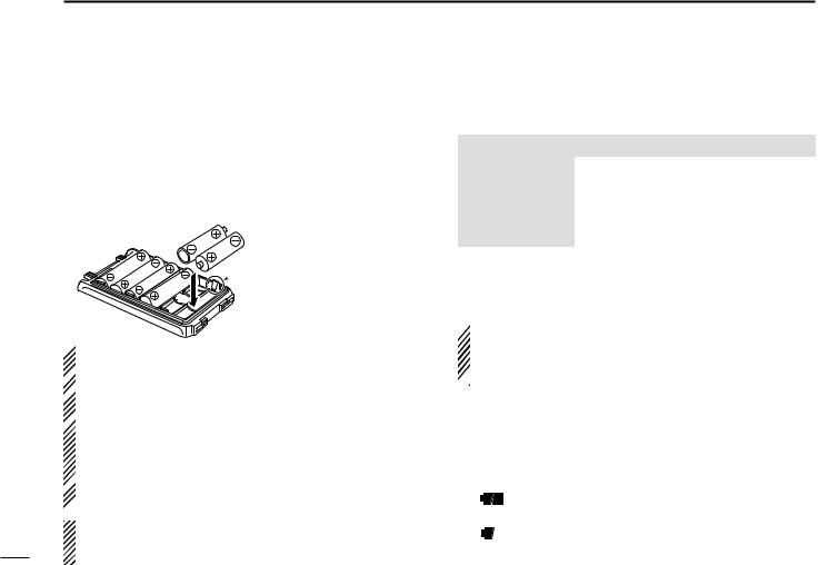
When using the battery case (BP-263), install 6 × AA (LR6) size alkaline batteries, as described below.
qRemove the battery case if it is attached. (p. 2) wInstall 6 × AA (LR6) size alkaline batteries.
•Install only alkaline batteries.
•Be sure to observe the correct polarity. eAttach the battery case. (p. 2)
Be careful! The negative
terminals of the battery case
 protrude from the body, so
pay attention not to injure your fingers when inserting the batteries.
 CAUTION:
• When installing batteries, make sure they are all the same  brand, type and capacity. Also, do not mix new and old bat-
  teries together.
• Keep battery terminals clean. It’s a good idea to clean bat-  tery terminals once a week.
• Never incinerate used battery cells since the internal bat-
tery gas may cause them to rupture.
• Never expose a detached battery case to water. If the battery  case gets wet, be sure to wipe it dry before using it.
 • Never use batteries whose insulated covering is damaged.
NOTE: When the battery case is attached, the battery protection function must be turned OFF in the Initial Set
mode (p. 47).
13
■ Battery information
D Battery life
Battery pack/case |
Voltage |
Capacity |
Battery life*1 |
|
BP-263 |
Battery case for |
—*2 |
||
AA (LR6) × 6 alkaline |
||||
|
|
|||
|
|
|
|
|
BP-264 |
7.2 V |
1400 mAh |
13 hrs. |
|
|
|
|
|
|
BP-265 |
7.4 V |
1900 mAh (min.) |
19 hrs. |
|
2000 mAh (typ.) |
||||
|
|
|
||
|
|
|
|
|
*1 When the power save function is set to “P–S.At,” and the operating time is calculated under the following conditions;
TX : RX : standby = 5 : 5 : 90
*2 The average operating life depends on the alkaline cells used.
 Even when the transceiver power is OFF, a small current still flows in the transceiver. Remove the battery pack/case when it won’t be used for a long time. Otherwise, the battery
  pack or the batteries in the case will become exhausted.
D Battery indication
The battery indicator, “ ,” appears when a battery pack/ case is attached to the transceiver.
Indicator |
Battery condition |
|
|
|
The battery has ample capacity. |
|
|
|
The battery is nearing exhaustion. |
|
Charging the battery pack, or replacing the batteries |
|
in the case is necessary. |
|
|
 Loading...