


Hi40402JO1E
Robot Operation Manual
HYUNDAI Robot
Hi4
HYUNDAI
HR100P
Hi4 CONTROLLER |
HR120S/150S |
|
HR006 |
HR015 |
HR010L |
HX130/165 |
The information presented in the manual is the property of HHI. Any copy or even partial is not allowed without prior written authorization from HHI. HHI reserves the right to modify without prior notification.
Printed in Korea - April/2002. 1st Edition
Copyright 2002 by Hyundai Heavy Industries Co.,Ltd.

|
|
|
|
|
|
|
|
|
|
|
|
|
|
|
|
|
|
|
|
|
|
|
|
|
|
|
|
|
|
|
|
|
|
|
|
|
|
|
|
|
|
|
|
|
|
|
|
|
|
|
|
|
|
|
|
|
|
|
|
|
|
|
|
|
|
|
|
|
|
|
|
|
|
|
|
|
|
|
|
|
|
|
|
|
|
|
|
|
|
|
|
|
|
|
|
|
|
|
■ |
HEAD OFFICE |
■ |
||||||||||||||||||||||||||||||
|
1, JEONHA-DONG, DONG-GU, |
1 |
||||||||||||||||||||||||||||||
|
ULSAN, KOREA |
|
|
|
||||||||||||||||||||||||||||
|
TEL: 82-52-230-7901~11 |
|
TEL: 052-230-7901~11 |
|||||||||||||||||||||||||||||
|
FAX: 82-52-230-7900 |
|
FAX: 052-230-7900 |
|||||||||||||||||||||||||||||
■ |
SEOUL OFFICE |
■ |
||||||||||||||||||||||||||||||
|
140-2,GYE-DONG, JONGNO-GU, |
140-2 |
||||||||||||||||||||||||||||||
|
SEOUL,KOREA |
|
14 |
|||||||||||||||||||||||||||||
|
TEL: 82-2-746-4711~5 |
|
TEL: 02-746-4711~5 |
|||||||||||||||||||||||||||||
|
FAX: 82-2-746-4720 |
|
FAX: 02-746-4720 |
|||||||||||||||||||||||||||||
■ |
DAEGU OFFICE |
|
■ |
|||||||||||||||||||||||||||||
|
223-5, BUMEO 2-DONG, |
|
2 235-5 |
|||||||||||||||||||||||||||||
|
SUSUNG-GU,DAEGU,KOREA |
|
6 |
|||||||||||||||||||||||||||||
|
TEL : 82-53-746-6232 |
|
TEL: 053-746-6232 |
|||||||||||||||||||||||||||||
|
FAX : 82-53-746-6231 |
|
FAX: 053-746-6231 |
|||||||||||||||||||||||||||||
■ |
CHEONAN OFFICE |
■ |
|
|||||||||||||||||||||||||||||
|
355-15,DAGA-DONG,CHEONAN-SI, |
355-15 |
||||||||||||||||||||||||||||||
|
CHUNGCHEONGNAM-DO,KOREA |
3 |
||||||||||||||||||||||||||||||
|
TEL: 82-41-576-4294~5 |
|
TEL: 041-576-4294~5 |
|||||||||||||||||||||||||||||
|
FAX: 82-41-576-4296 |
|
FAX: 041-576-4296 |
|||||||||||||||||||||||||||||
■ |
GWANGJU OFFICE |
■ |
|
|||||||||||||||||||||||||||||
|
415-12,NONGSUNG-DONG, |
|
415-12 |
|||||||||||||||||||||||||||||
|
SEO-GU,GWANGJU,KOREA |
|
3 |
|||||||||||||||||||||||||||||
|
TEL: 82-62-363-5272 |
|
TEL: 062-363-5272 |
|||||||||||||||||||||||||||||
|
FAX: 82-62-363-5273 |
|
FAX: 062-363-5273 |
|||||||||||||||||||||||||||||

------------------------------------------------------------------------------------------------
Contents
Chapter 1. Safety, Operation panel, Teach Pendant
1.1 |
Safety ..................................................... |
|
|
1 |
- 2 |
1.1.1 |
General .................................................... |
|
|
1 |
- 2 |
1.1.2 |
Relevant safety |
standard ................................... |
|
1 |
- 5 |
1.1.3 |
Safety training |
............................................ |
|
1 |
- 5 |
1.1.4 |
Safety marking ............................................. |
|
|
1 |
- 5 |
1.1.5 |
Definition of safety functions ............................. |
|
1 |
- 7 |
|
1.1.6 |
Installation of |
robot ...................................... |
|
1 |
- 8 |
1.1.7 |
Safety working procedures ................................. |
1 |
|
- 15 |
|
1.1.8 |
Safety measures |
for entering safety fence ................. |
1 |
|
- 20 |
1.1.9 |
Safety measures |
for maintenance and repair ................ |
1 |
|
- 21 |
1.1.10 |
Safety function |
........................................... |
1 |
|
- 24 |
1.1.11 |
Safety related to end effectors ........................... |
1 |
|
- 28 |
|
1.1.12 |
Liabilities ............................................... |
|
1 |
|
- 29 |
1.2 |
Operation Panel............................................ |
|
1 |
|
- 31 |
1.2.1 |
External shape of operation panel ......................... |
1 |
|
- 31 |
|
1.2.2 |
Buttons of operation panel ................................ |
1 |
|
- 31 |
|
1.3 |
Teach pendant ............................................. |
|
1 |
|
- 33 |
1.3.1 |
External shape of teach pendant ........................... |
1 |
|
- 33 |
|
1.3.2 |
Screen of teach |
pendant ................................... |
1 |
|
- 34 |
1.3.3 |
Keys of teach pendant ..................................... |
1 |
|
- 35 |
|
Chapter 2. Basic operation of robot
2.1 |
Basic operation |
............................................ |
2 |
- 2 |
2.1.1 |
Controller's power/motor ...........................ON/OFF |
2 |
- 2 |
|
2.1.1.1 |
Power ON/Motor ........................................ON |
2 |
- 2 |
|
2.1.1.2 |
Power OFF/Motor ....................................... |
OFF |
2 |
- 2 |
2.1.2 |
How to initiate ................................ |
the system |
2 |
- 3 |
2.1.3 |
Teaching .................................................. |
|
2 |
- 3 |
2.1.4 |
Step and function ......................................... |
2 |
- 4 |
|
----------------------------------------------------------------------------------------
- 1 -

------------------------------------------------------------------------------------------------
2.2 |
Basic things for step ....................................... |
2 |
- 5 |
2.2.1 |
The parameter of STEP command line ........................ |
2 |
- 5 |
2.2.1.1 |
Interpolation-locus from between step and step ............ |
2 |
- 6 |
2.2.1.2 |
Pose ..................................................... |
2 |
- 7 |
2.2.1.3 |
Speed .................................................... |
2 |
- 8 |
2.2.1.4 |
Accuracy ................................................. |
2 |
- 8 |
2.2.1.5 |
Tool number .............................................. |
2 |
- 8 |
2.2.1.6 |
Output option ............................................ |
2 |
- 8 |
2.2.1.7 |
Stop condition ............................................ |
2 |
- 9 |
2.2.1.8 |
Stop state variable ...................................... |
2 |
- 9 |
2.2.2 |
Step position validation/modification method.............. |
2 |
- 10 |
2.2.2.1 |
Encoder coordinate system ................................ |
2 |
- 10 |
2.2.2.2 |
Base/Robot coordinate system ............................ |
2 |
- 11 |
2.1.4 |
Coordinate system ........................................ |
2 |
- 13 |
2.3.1 |
JOG operation key ....................................... |
2 |
- 13 |
2.3.2 |
Axis coordinate ......................................... |
2 |
- 14 |
2.3.3 |
Robot coordinate ........................................ |
2 |
- 15 |
2.3.4 |
User coordinate ......................................... |
2 |
- 17 |
2.3.5 |
Tool coordinate ......................................... |
2 |
- 18 |
2.4 |
Auto tool setting ........................................ |
2 |
- 19 |
Chapter 3. Service menu
3.1 |
Monitoring .................................................... |
|
3 - 4 |
3.2 |
Register ..................................................... |
3 |
- 15 |
|
3.2.1 XYZ Shift register ................................... |
3 |
- 16 |
|
3.2.2 Shift buffers ........................................ |
3 |
- 18 |
|
3.2.3 On-line shift register Group.......................... |
3 |
- 20 |
|
3.2.4 Palletizing register.................................. |
3 |
- 22 |
|
3.2.5 Frequency condition register.......................... |
3 |
- 25 |
|
3.2.6 Conveyor data ........................................ |
3 |
- 26 |
3.3 |
Variable ...................................................... |
3 |
- 28 |
3.4 |
Edit program .................................................. |
3 |
- 29 |
|
3.4.1 Modify writing condition totally...................... |
3 |
- 30 |
|
3.4.2 Modify speed in record totally........................ |
3 |
- 31 |
|
3.4.3 Modify position in record totally..................... |
3 |
- 32 |
|
3.4.4 Step copy ........................................... |
3 |
- 34 |
----------------------------------------------------------------------------------------
- 2 -

------------------------------------------------------------------------------------------------
3.4.5 Step reverse copy..................................... |
3 |
- 36 |
3.4.6 Edit program in running (Hot edit) ................... |
3 |
- 38 |
3.5 File management................................................ |
3 |
- 43 |
3.5.1 Internal memory file name ............................ |
3 |
- 44 |
3.5.2 Program first data.................................... |
3 |
- 45 |
3.5.3 Internal program axis no.............................. |
3 |
- 46 |
3.5.4 Rename ............................................... |
3 |
- 47 |
3.5.5 Copy.................................................. |
3 |
- 51 |
3.5.6 Delete ............................................... |
3 |
- 53 |
3.5.7 Protect............................................... |
3 |
- 55 |
3.5.8 Storage media format ................................. |
3 |
- 58 |
3.5.9 Save/Load (SRAM Card) ................................ |
3 |
- 59 |
3.6 Program conversion............................................. |
3 |
- 61 |
3.6.1 Coordinate transformation ............................ |
3 |
- 62 |
3.6.2 Mirror Image.......................................... |
3 |
- 64 |
3.6.3 Off-Line XYZ shift ................................... |
3 |
- 67 |
3.7 System checking ............................................... |
3 |
- 69 |
3.7.1 System version........................................ |
3 |
- 70 |
3.7.2 Run time ............................................. |
3 |
- 71 |
3.7.3 Diagnosis of troubles................................. |
3 |
- 74 |
3.7.4 Error logging ........................................ |
3 |
- 76 |
3.7.5 Stop history ......................................... |
3 |
- 78 |
3.7.6 Operation history .................................... |
3 |
- 80 |
3.8 Date setting (Date, Time) ..................................... |
3 |
- 81 |
Chapter 4. Condition setting
4.1 |
Cycle type ...................................................... |
4-3 |
4.2 |
Step go/back max. speed.......................................... |
4-3 |
4.3 |
Function in step go/back......................................... |
4-4 |
4.4 |
Speed rate....................................................... |
4-4 |
4.5 |
Robot lock....................................................... |
4-5 |
4.6 |
Record speed type................................................ |
4-5 |
4.7 |
Interpolation base............................................... |
4-6 |
4.8 |
User coordinate ................................................. |
4-6 |
----------------------------------------------------------------------------------------
- 3 -

------------------------------------------------------------------------------------------------
Chapter 5. Application condition
5.1 |
Conveyor operation .......................................... |
5 |
- 3 |
5.2 |
Search range ................................................ |
5 |
- 4 |
5.3 |
Search reference position record ............................. |
5 |
- 4 |
5.4 |
Spot welding ................................................ |
5 |
- 5 |
5.5 |
Gun search reference record .................................. |
5 |
- 6 |
5.6 |
Output(DO) signal clear ...................................... |
5 |
- 7 |
5.7 |
Online shift register clear .................................. |
5 |
- 7 |
Chapter 6. System setting
6.1 |
User configuration .......................................... |
|
6 |
- 5 |
|
6.1.1 Display language ..................................... |
|
6 |
- 6 |
|
6.1.2 Pose reocrd type .................................... |
|
6 |
- 6 |
|
6.1.3 Start type ........................................... |
|
6 |
- 7 |
|
6.1.4 Change of cursor position in auto mode ............... |
|
6 |
- 7 |
|
6.1.5 Confirm when the command delete....................... |
|
6 |
- 8 |
|
6.1.6 WAIT(DI/WI) forcible release ......................... |
|
6 |
- 8 |
|
6.1.7 Dettachment of Teach Pendant ......................... |
|
6 |
- 9 |
|
6.1.8 Power failure detection(Not changeable) .............. |
|
6 |
- 9 |
|
6.1.9 External program selection ........................... |
|
6 |
- 9 |
|
6.1.10 Using the program strobe signal .................... |
6 |
|
- 10 |
|
6.1.11 Step set alarm type................................. |
6 |
|
- 11 |
|
6.1.12 Lowest position proportion of the cursor ........... |
6 |
|
- 11 |
|
6.1.13 Using the collision sensor ......................... |
6 |
|
- 12 |
6.2. |
Controller parameter ....................................... |
6 |
|
- 13 |
|
6.2.1 Input/output signal selection ....................... |
6 |
|
- 14 |
|
1: Input signal logic ............................... |
6 |
|
- 15 |
|
2: Output signal logic .............................. |
6 |
|
- 16 |
|
3: The attribution of output signal ................. |
6 |
|
- 17 |
|
4: Setting the pulse table .......................... |
6 |
|
- 18 |
|
5: Setting the delay table .......................... |
6 |
|
- 19 |
|
6: Output signal assignment ......................... |
6 |
|
- 20 |
|
7: Input signal assignment .......................... |
6 |
|
- 21 |
|
8: Setting the earlier output ....................... |
6 |
|
- 23 |
|
9: DIO name edit..................................... |
6 |
|
- 24 |
----------------------------------------------------------------------------------------
- 4 -

------------------------------------------------------------------------------------------------
|
10: Setting the field bus ............................. |
6 |
- 26 |
|
|
6.2.2 |
Serial port ......................................... |
6 |
- 31 |
|
|
1: Teach Pendant (CNTP) ............................. |
6 |
- 31 |
|
|
2: Private serial port for I/O board ................ |
6 |
- 31 |
|
|
3: Serial port #1 (CNSIO) ........................... |
6 |
- 32 |
|
|
4: Serial port #2 (OPSIO) ........................... |
6 |
- 33 |
|
6.2.3 |
Robot ready ......................................... |
6 |
- 34 |
|
6.2.4 |
Home position registration .......................... |
6 |
- 35 |
|
6.2.5 |
Return to the previous position ..................... |
6 |
- 36 |
|
6.2.6 |
End relay output time ............................... |
6 |
- 37 |
|
6.2.7 |
Interlock error time ................................ |
6 |
- 38 |
|
6.2.8 |
External error output ............................... |
6 |
- 39 |
|
6.2.9 |
Power Saving : PWM OFF .............................. |
6 |
- 42 |
|
6.2.10 Shift limit ........................................ |
6 |
- 43 |
|
|
6.2.11 Setting the user key ............................... |
6 |
- 44 |
|
|
6.2.12 Coordination system registration ................... |
6 |
- 46 |
|
|
|
1: User coordination registration ................... |
6 |
- 46 |
|
|
2: Pedestal tool coordination system ................ |
6 |
- 48 |
6.3 |
Machine |
parameter............................................ |
6 |
- 49 |
|
6.3.1 |
Tool data ........................................... |
6 |
- 50 |
|
6.3.2 |
Axis Constant ....................................... |
6 |
- 54 |
|
6.3.3 |
Soft limit .......................................... |
6 |
- 55 |
|
6.3.4 |
Arm interference angle .............................. |
6 |
- 56 |
|
6.3.5 |
Encoder offset calibration .......................... |
6 |
- 57 |
|
6.3.6 |
Accel./Decel. speed parameter ....................... |
6 |
- 59 |
|
6.3.7 |
B axis dead zone .................................. |
6 |
- 60 |
|
6.3.8 |
Accuracy ............................................ |
6 |
- 61 |
|
6.3.9 |
Speed ............................................... |
6 |
- 64 |
|
6.3.11 Additional load per each axis ...................... |
6 |
- 65 |
|
6.4 |
Application parameter ....................................... |
6 |
- 67 |
|
|
6.4.1 |
Spot & Stud ......................................... |
6 |
- 68 |
|
|
1: Welding parameter ................................ |
6 |
- 69 |
|
|
2: Servo gun parameter .............................. |
6 |
- 71 |
|
|
3: Spot welding data(condition,sequence) ............ |
6 |
- 76 |
|
|
4: Equalizing parameter ............................. |
6 |
- 81 |
----------------------------------------------------------------------------------------
- 5 -

------------------------------------------------------------------------------------------------
6.4.2 Arc ................................................ |
6 |
- 83 |
6.4.3 Palletizing ........................................ |
6 |
- 85 |
1: Palletizing pattern register ..................... |
6 |
- 86 |
2: Pallete dip angle measurement .................... |
6 |
- 90 |
6.4.6 Conveyor ........................................... |
6 |
- 91 |
1: Conveyor constant setting ........................ |
6 |
- 92 |
2: Automatic setting of conveyor parameter .......... |
6 |
- 95 |
6.4.7 Speed proportion voltage output ..................... |
6 |
- 96 |
6.5 System format ............................................... |
6 |
- 98 |
6.5.1 System format ....................................... |
6 |
- 99 |
6.5.2 Robot type |
selection ................................ |
6 |
- 100 |
6.5.4 Use setting |
........................................ |
6 |
- 103 |
6.5.5 Positioner |
group setting ............................ |
6 |
- 104 |
6.6 Automatic constant setting ................................. |
6 |
- 106 |
|
6.6.1 The optimization axis constant ...................... |
6 |
- 107 |
|
6.6.4 Positioner calibration .............................. |
6 |
- 109 |
|
Chapter 7. R code
7. |
1 |
(1) |
R0 |
Step counter reser ............................ |
|
7 |
- 5 |
7. |
2 |
(2) |
R5 |
External start selection ...................... |
|
7 |
- 5 |
7. |
3 |
(3) |
R6 |
External program selection..................... |
|
7 |
- 6 |
7. |
4 |
(4) |
R10 |
Run time display............................... |
|
7 |
- 7 |
7. |
5 |
(5) |
R17 |
File name display in internal memory ......... |
7 |
|
- 10 |
7. |
6 |
(6) |
R18 |
Frequency condition register.................. |
7 |
|
- 11 |
7. |
7 |
(7) |
R29 |
Tool number setting .......................... |
7 |
|
- 12 |
7. |
8 |
(8) |
R44 |
Conveyor data clear .......................... |
7 |
|
- 13 |
7. |
9 |
(9) |
R45 |
Conveyor register manual input ............... |
7 |
|
- 14 |
7.10 |
(10) |
R46 |
Manual conveyor limit switch on .............. |
7 |
|
- 15 |
|
7.11 |
(11) |
R49 |
Speed variation setting ...................... |
7 |
|
- 16 |
|
7.12 |
(12) |
R55 |
Palletize counter reset ...................... |
7 |
|
- 17 |
|
7.13 |
(13) |
R71 |
Recorded speed selection...................... |
7 |
|
- 18 |
|
7.14 |
(14) |
R107 |
Program head data display .................... |
7 |
|
- 19 |
|
7.15 |
(15) |
R115 |
Program copy ................................. |
7 |
|
- 19 |
|
7.16 |
(16) |
R116 |
Program number modification .................. |
7 |
|
- 20 |
|
7.17 |
(17) |
R117 |
Program delete ............................... |
7 |
|
- 21 |
|
----------------------------------------------------------------------------------------
- 6 -

------------------------------------------------------------------------------------------------
7.18 |
(18) |
R123 |
Robot lock ................................... |
7 |
- 22 |
7.19 |
(19) |
R136 |
Modify accuracy in steps ..................... |
7 |
- 23 |
7.20 |
(20) |
R137 |
Modify MX in steps ............................ |
7 |
- 24 |
7.21 |
(21) |
R138 |
Modify GUN in steps .......................... |
7 |
- 25 |
7.22 |
(22) |
R162 |
Shift register value change .................. |
7 |
- 26 |
7.23 |
(23) |
R163 |
On-line shift cancel ......................... |
7 |
- 26 |
7.24 |
(24) |
R204 |
Spot welding condition manual output ......... |
7 |
- 27 |
7.25 |
(25) |
R210 |
Serovo gun number selection .................. |
7 |
- 28 |
7.26 |
(26) |
R211 |
Squeeze force setting ........................ |
7 |
- 28 |
7.27 |
(27) |
R212 |
Moving-tip consumption preset ................. |
7 |
- 29 |
7.28 |
(28) |
R213 |
Fixed-tip consumption preset .................. |
7 |
- 29 |
7.29 |
(29) |
R219 |
Equalizerless gun number selection ........... |
7 |
- 30 |
7.30 |
(30) |
R220 |
Equalizerless tip consumption preset .......... |
7 |
- 30 |
7.31 |
(31) |
R245 |
Monitor mode selection ........................ |
7 |
- 31 |
7.32 |
(32) |
R269 |
Memory protection setting ..................... |
7 |
- 32 |
7.33 |
(33) |
R286 |
Software version display ...................... |
7 |
- 33 |
7.34 |
(34) |
R310 |
Manual output of GO-signal .................... |
7 |
- 34 |
7.35 |
(35) |
R320 |
Set max. speed of step go/back ................ |
7 |
- 35 |
7.36 |
(36) |
R323 |
Robot interrupt function record ............... |
7 |
- 36 |
7.37 |
(37) |
R341 |
Execution code back-up ....................... |
7 |
- 40 |
Chapter 8. Programming
8.1 |
Edit step..................................................... |
|
8 |
- 3 |
8.2 |
Summary of operation keys..................................... |
|
8 |
- 4 |
8.3 |
Edit command.................................................. |
|
8 |
- 6 |
8.4 |
Example - move sentence....................................... |
|
8 |
- 7 |
8.5 |
Variable, numerical formula and string edit .................. |
8 |
- 13 |
|
8.6 |
Line number edit............................................. |
8 |
- 17 |
|
8.7 |
Block edit................................................... |
8 |
- 18 |
|
Chapter 9. Quick open function
9.1 |
Function summary............................................ |
9 |
- 2 |
||
9.2 |
Move - step |
position........................................ |
9 |
- 4 |
|
9.3 |
Welding start con. - execution at ASF#=X .................... |
9 |
- |
5 |
|
9.4 |
Welding end |
con. - execution at AEF#=X ...................... |
9 |
- |
7 |
----------------------------------------------------------------------------------------
- 7 -
------------------------------------------------------------------------------------------------
9.5 |
Welding aux. con. - |
retry .................................. |
|
9 - 9 |
9.6 |
Welding aux. con. - |
restart................................ |
9 |
- 11 |
9.7 |
Welding aux. con. - |
auto. wire stick release............... |
9 |
- 14 |
9.8 |
Weaving condition file .................................... |
9 |
- 15 |
|
9.9 |
Program edit in running ................................... |
9 |
- 17 |
|
9.10 |
Spot welding function ..................................... |
9 |
- 18 |
|
9.10.1 |
Welding condition ................................... |
..... |
9 |
- 18 |
9.10.2 |
Welding sequence ..................................... |
..... |
9 |
- 19 |
Chapter 10. Menu tree
10.1 |
MENU LIST .................................................. |
10 |
- 2 |
10.2 |
MOTION I/O ................................................. |
10 |
- 3 |
10.3 |
FLOW CONTROL ............................................... |
10 |
- 5 |
10.4 |
ETC. ....................................................... |
10 |
- 7 |
10.5 |
ARC ........................................................ |
10 |
- 8 |
10.6 |
SUSTITUTIAL STATEMENT ..................................... |
10 - 10 |
|
Chapter 11. Robot language explanation
11.1 |
BASIC ELEMENTS ............................................ |
11 - 3 |
|
|
11.1.1 LINE ............................................. |
11 - 3 |
|
|
11.1.2 CHARACTER ........................................ |
11 - 3 |
|
|
11.1.3 ADDRESS .......................................... |
11 - 3 |
|
|
11.1.4 CONSTANT ........................................ |
11 - 4 |
|
|
11.1.5 ROBOT CONFIG. INFORMATION.......................... |
11 - 5 |
|
|
11.1.6 VARIABLE ......................................... |
11 - 6 |
|
|
11.1.7 OPERATOR ........................................ |
11 |
- 10 |
|
11.1.8 FORMULA ......................................... |
11 |
- 10 |
11.2 |
COMMAND LINE .............................................. |
11 |
- 11 |
|
11.2.1 SUSTITUTIONAL ................................... |
11 |
- 11 |
|
11.2.2 ROBOT CONTROL ................................... |
11 |
- 12 |
|
11.2.3 INPUT/OUTPUT .................................... |
11 |
- 14 |
|
11.2.4 PROGRAM FLOW CONTROL ............................. |
11 |
- 16 |
|
11.2.5 COMMENT ......................................... |
11 |
- 21 |
|
11.2.6 ARC WELDING ..................................... |
11 |
- 21 |
11.3 |
OTHERS. ................................................... |
11 |
- 25 |
----------------------------------------------------------------------------------------
- 8 -

------------------------------------------------------------------------------------------------
11.4 FUNCTION |
................................................... |
11 |
- 40 |
|
11.4.1 ............................. |
ARITHEMATIC FUNCTION |
11 |
- 40 |
|
11.4.2 .................................. |
STRING FUNCTION |
11 |
- |
41 |
11.4.3 |
ROBOT LANGUAGE SUBTITUTION OF OLD MIT FUNCTION CODE |
11 |
- |
42 |
Chapter 12. Signal connection
12.1 |
EXTERNAL INPUT SIGNAL (BD430/BD431) ......................... |
12 |
- 2 |
12.2 |
EXTERNAL OUTPUT SIGNAL (BD430/BD431) ........................ |
12 |
- 7 |
12.3 |
BD481 CIRCUIT ............................................. |
12 - 17 |
|
----------------------------------------------------------------------------------------
- 9 -

1. Safety, Operation Panel, Teach Pendant (1) Safety
------------------------------------------------------------------------------------------------
Chapter 1.Safety, Operation panel, Teach pendant
Contents
1.1 |
Safety ..................................................... |
|
|
1 |
- 2 |
1.1.1 |
General .................................................... |
|
|
1 |
- 2 |
1.1.2 |
Relevant safety |
standard ................................... |
|
1 |
- 5 |
1.1.3 |
Safety training |
............................................ |
|
1 |
- 5 |
1.1.4 |
Safety marking ............................................. |
|
|
1 |
- 5 |
1.1.5 |
Definition of safety functions ............................. |
|
1 |
- 7 |
|
1.1.6 |
Installation of |
robot ...................................... |
|
1 |
- 8 |
1.1.7 |
Safety working procedures ................................. |
1 |
|
- 15 |
|
1.1.8 |
Safety measures |
for entering safety fence ................. |
1 |
|
- 20 |
1.1.9 |
Safety measures |
for maintenance and repair ................ |
1 |
|
- 21 |
1.1.10 |
Safety function |
........................................... |
1 |
|
- 24 |
1.1.11 |
Safety related to end effectors ........................... |
1 |
|
- 28 |
|
1.1.12 |
Liabilities ............................................... |
|
1 |
|
- 29 |
1.2 |
Operation Panel............................................ |
|
1 |
|
- 31 |
1.2.1 |
External shape of operation panel ......................... |
1 |
|
- 31 |
|
1.2.2 |
Buttons of operation panel ................................ |
1 |
|
- 31 |
|
1.3 |
Teach pendant ............................................. |
|
1 |
|
- 33 |
1.3.1 |
External shape of teach pendant ........................... |
1 |
|
- 33 |
|
1.3.2 |
Screen of teach |
pendant ................................... |
1 |
|
- 34 |
1.3.3 |
Keys of teach pendant ..................................... |
1 |
|
- 35 |
|
--------------------------------------------------------------------------------
1 - 1

1. Safety, Operation Panel, Teach Pendant (1) Safety
------------------------------------------------------------------------------------------------
Chapter 1. Safety, Operation panel, Teach Pendant
1.1Safety
1.1.1General
The primary purpose of this Chapter is to define the safety of the user and operating personnel when using Hyundai Industrial Robots i. e. HR series and HX series robot together with Hi-4 Controller (Hereinafter referred to "the Robotics System").
This manual covers any functions and safety measures required for the operation and maintenance of the Robotics System itself. However, this manual does neither cover how to design, install and operate a complete work cell, nor all peripheral equipment and tooling which can influence the safety of the complete work cell.
This manual enumerates the safety instructions and/or recommendations for robot manipulatorandcontrollerinstrictlyaccordancewiththeAmericanNationalStandard Safety Requirements for industrial robots "ANSI/RIA R15.06-1999".
The technical description and installation method of the Robotics System are presented in detail at this Operation Manual and the relevant specifications for the robot manipulator and controller.
All personnel who intend to install, operate, program, repair, adjust, maintain or otherwise use the Robotics System must be trained in an approved Hyundai Robotics training course and have a good understanding and knowledge of this Operation Manual and the Maintenance Manual, and further pay their special attention and observation to the articles marked with the symbol which are of paramount importance among the articles in this Chapter 1 "Safety".
Installation, replacement, adjustment, operation, maintenance and repair of the Robotics System must be performed by the personnel who was duly trained in an approved Hyundai robotics training course and become familiar with the proper operation of the Robotics System according to the instructions specified in Operation and
--------------------------------------------------------------------------------
1 - 2

1. Safety, Operation Panel, Teach Pendant (1) Safety
------------------------------------------------------------------------------------------------
Maintenance Manual. Hyundai maintains its various application-specific training courses for domestic and foreign customers respectively.
All owners, employers or users of the Robotics System have the responsibility to review and observe any appliable safety laws and regulations in each country and to take the necessary steps to guarantee the correct design, installation and operation of all safety devices which can secure safety of all personnel in the workplace.
InaccordancewiththeAmericanNationalStandardSafetyRequirementsforindustrial robots "ANSI/RIA R15.06-1999", the dangerous zones of the Robotics System, i. e. the working range in which the robot together with tools, accessories and additional equipment moves, must in all cases be safeguarded to prevent persons or objects from entering the dangerous zones or to ensure that the robot system is immediately shut down by Emergency Stop system if a person or object should nevertheless enter a dangerous zone. All owners, employers or users of the Robotics System have the responsibility to take all necessary steps to make correct installation, examination and operation of the relevant safety equipments.
This manual provides specific information regarding the operation of Hyundai Hi-4 Controller together with the following robot manipulator models for the possible application usages as mentioned below;
Available manipulator Type
HR006F(floor mounting type, 6kg)
HR006V(wall mounting type, 6kg)
HR015F(floor mounting type, 15kg)
HR015V(wall mounting type, 15kg)
HR050F(floor mounting type, 50kg)
HR050V(wall mounting type, 50kg)
HR100P(for palletizing application, 100kg)
HR130IIF(floor mounting type, 130kg)
HR130IIV(wall mounting type, 130kg)
HR120S (shelf mounting type, 120kg)
HR150S (shelf mounting type, 150kg)
HX130F (floor mounting type, 130kg)
--------------------------------------------------------------------------------
1 - 3

1. Safety, Operation Panel, Teach Pendant (1) Safety
------------------------------------------------------------------------------------------------
HX130V (wall mounting type, 130kg)
HX130S (shelf mounting type, 130kg)
HX165F (floor mounting type, 165kg)
HX165V (wall mounting type, 165kg)
HX165S (shelf mounting type, 165kg)
Possible Application Usages
The Robotics System is a standard six-axis but additional axis available industrial robot for installation on the floor, on the wall or on the shelf. It is suitable for both point-to-point and continuous-path controlled tasks.
The main areas of application are
-Spot welding
-Material Handling
-Assembly
-Application of adhesives, sealants and preservatives
-MIG/MAG welding
-Palletizing and Depalletizing
-Grinding
All owners, employers or users who intend to use the Robotics System for any other purposes than the above-mentioned must request Hyundai's prior consideration and confirmation whether it can be applied without failure and/or problems or not. Please contact our Customer Satisfaction Department or your local distributor in order to check and confirm it before any users implement any special applications of the Robotics System.
Invalid environments
The Robotics System is strictly prohibited to be located, installed, maintained, used or operated in an explosive environment and any areas contaminated by oil, flammable material or chemical material.
--------------------------------------------------------------------------------
1 - 4

1. Safety, Operation Panel, Teach Pendant (1) Safety
------------------------------------------------------------------------------------------------
1.1.2 Relevant Safety Standards
The Robotics System is designed as per ISO 10218, January 1992 edition that specifies the Safety Requirements for Industrial Robots and furthermore in strictly accordance with the ANSI/RIA 15.06 -1999 Safety Requirements.
1.1.3 Safety Training
All the personnel who intend to teach, operate or examine the Robotics System must betrainedinanapprovedHyundaiRoboticsoperationandsafetytrainingcoursebefore starting the teaching, operation or examination of the Robotics System.
The objective of the operation and safety training course is to provide information on:
-the purpose of safety devices and their function
-safety procedures for handling the Robotics System
-performances of the robot or the Robotics System and possible hazards
-tasks associated with any specific robot applications
-safety concepts
1.1.4Safety Marking
1.1.4.1 Safety Symbols
For the purpose of effective safety instructions, the following safety symbols are used in this manual.
--------------------------------------------------------------------------------
1 - 5

1. Safety, Operation Panel, Teach Pendant (1) Safety
------------------------------------------------------------------------------------------------
means WARNING:
!means MANDATORY:
means PROHIBTED:
1.1.4.2 Safety Marking
Indicate a potentially hazardous situation which, if not avoided, could result in death or serious injury to personnel and damage to equipment. The special attention to the careful operation and handling must be paid by owner, employer, operator or user.
Indicate the compulsory measures that should be performed by owner, employer, operator and user
Indicate the prohibited actions and/or operations that should not be performed by
Identification plates, warning labels and safety symbols are attached to the robot manipulator and to the inside and outside of control cabinet. The designation labels and position marks are also attached to the following cables.
-Wire harness between the robot manipulator and the control cabinet
-All the electric cables in and outside both robot manipulator and control cabinet
All of these plates, labels, symbols and marks constitute safety-relevant parts of the Robotics System. They must remain attached to the robot manipulator or control cabinet at their cleary visible positions all the time.
The painted markings on the floor and the signs indicating the dangerous zones must be clearly different in form, color and style from other markings on the machine near to the Robotics System or inside the plant facilities where the Robotics System is installed.
It is forbidden to remove, erase, cover, paint over or alter by way of editing or spoiling the cleary visible identification plates, warning labels, safety symbols, designation labels and cable marks
--------------------------------------------------------------------------------
1 - 6

1. Safety, Operation Panel, Teach Pendant (1) Safety
------------------------------------------------------------------------------------------------
1.1.5. Definition of Safety Functions
Emergency Stop FunctionIEC 204-1,10,7
Thereisoneemergencystopbuttononthecontrollerandanotherontheteachpendant. If necessary, additional emergency buttons can be connected to the robot's safety chain circuit. The emergency stop function, which overrides all other robot controls, removes drive power from robot axis actuators, stop all moving parts and disconnect power in order not to use other dangerous functions controlled by the robot.
Safety Stop Function-ISO 10218(EN 775), 6.4.3
When a safety stop circuit is provided, each robot must be delivered with the necessaryconnectionsforthesafeguardsandinterlocksassociatedwiththiscircuit. The robot has a number of electrical inputs which can be used to connect external safety equipment, such as safety gates and light curtains. This allows the robot's safety functions to be activated both by peripheral equipment and by the robot itself.
Speed Limitation Function-ISO 10218(EN 775), 3.2.17
In manual mode, the speed of robot is strictly limited to 250 mm per second as a maximum. The speed limitation applies not only to the TCP(Tool Center Point), but to all parts of robot. The speed of equipment mounted on the robot can be monitored.
Working Envelope RestrictionANSI/RIA R15.06-1999
The working envelop of each robot axes can be restricted using software limits. Axis 1,2,3 can also be restricted by means of mechanical stops.
Operation Mode SelectionANSI/RIA R15.06-1999
The robot can be operated either manually or automatically. In manual mode, the robot can be operated by using the teach pendant only, i. e. not by any external equipment.
--------------------------------------------------------------------------------
1 - 7

1. Safety, Operation Panel, Teach Pendant (1) Safety
------------------------------------------------------------------------------------------------
1.1.6. Installation of Robot
!1.1.6.1 Safety Fence
(1)Install Safety Fence away from the working space of robot in order to prevent from any possible collision and interface between workers and robot during the robot operation.
Any accidents can be take place when any workers or any other persons enter inside the safety fence without protective actions. Safety fence shall be equipped with the emergency stop mechanism that can activate emergency stop of robot if any workers would get into the safety fence for examination of robot and welding equipment and replacement of tip dresser and tip etc. during robot operation.
(2) Safety Fence shall fully cover the working space of robot and be installed to secure the enough space in order to evade any interference with robot during teaching and repair operation of workers within the safety fence. And it shall be
--------------------------------------------------------------------------------
1 - 8
1. Safety, Operation Panel, Teach Pendant (1) Safety
------------------------------------------------------------------------------------------------
tightly fixed to the floor and have the relevant structure not to easily get over the safety fence.
(3)Safety fence shall be fixed installation type and have no dangerous elements such as sharp edges and rough profile etc.
(4)Gate shall be installed at Safety Fence. Safety plug shall be attached to gate. Unless unplug the safety plug from gate, gate shall not be opened. In case of unplugging the safety plug, robot shall be motor off by interlock signal. It shall be hard-wired to cause motors off the robot whenever the gate is opened. (Please refer to Chapter 12.)
(5)In case of robot operation at the state of unplugging safety plug, it shall be hard-wired to become a low speed playback mode. (Please refer to Chapter 12)
(6)Emergency stop button shall be installed at workers' easily accessible distance.
(7)If there is no safety fence, a photoelectric switch or mat switch instead of safety plugshall beinstalledat allthe spaces withinthe workingrange ofrobot. Whenever workers enter the working range of robot, robot will be automatically stopped.
(8)Working space of robot as the dangerous area shall be clearly marked by painting on the floor.
!1.1.6.2. Installation of robot and peripheral equipment
(1)Execute the connection work after ensuring the power-off status. There are many risks of receiving electric shock due to the usage of high voltage power source such as 220V, 440V, 80V etc. in case of primary power source connection to robot controller or peripheral equipment.
(2)Attach the warning tag "No-Access during Operation" at the gate of safety fence and further educate it as a precaution
(3)Locate controller, interlock panel and any other operation panels outside safety fence.
--------------------------------------------------------------------------------
1 - 9

1. Safety, Operation Panel, Teach Pendant (1) Safety
------------------------------------------------------------------------------------------------
(4)In case of installation of operation stand, attach emergency stop button on it. Emergency stop shall be available at any time from any locations that can operate the robot.
(5)Execute cabling and piping work in proper way for robot manipulator, controller, interlock panel, timer etc. Any loose or protruded cables and/or wires can cause workers' slippery or disconnection of cable by fork lift.
!(6) Locate robot manipulator, controller and operation stand where workers can clearly see the movement of robot manipulator. When operator do not acknowledge abnormal situation of robot or other workers' working at the robot due to the invisible situation, operator's robot operation can cause a large accident.
(7)Limit the workable space of robot by utilizing soft limit or mechanical stopper etc. when the required work space of robot is smaller than the workable space of robot. In case of abnormal operation, any excessive working out of the workable space can be stopped previously. (Please refer to Operation and Manipulator Maintenance Manual)
(8)Install safety curtain or cover for spatters made during welding work which can cause personal injury or fire accident. In any case, safety curtain or cover shall be installed to allow operator to clearly see the movement of robot manipulator.
(9)Automatic operation and manual operation which mean the actual operation state of robot shall be notified to workers even in the distance by easily visible light or device. Install buzzer or alarming light for sign of starting automatic operation of robot.
(10)Removeanyprotrusions,sharpedgesatequipments,devicesaroundtherobotwhich can cause personal injury or any other accidents.
(11)Input and output of workpiece by inserting worker's hands inside safety fence shall be strictly prohibited due to the risks of pressure or cutting injury accident.
--------------------------------------------------------------------------------
1 - 10

1. Safety, Operation Panel, Teach Pendant (1) Safety
------------------------------------------------------------------------------------------------
! 1.1.6.3. Robot installation
Install robot as per the planning and layout which has been previously reviewed and studied for the optimized performance and functionality of the robot. In case of bad installation situation of robot, the serious problems can take place as follows;
-Error of relative position between robot and workpiece during operation.
-Bad performance quality of robot caused by vibration.
-Shortening lifetime of robot
-Cause of serious accidents
The following lists the safety precautions to which careful consideration must be made by operator, worker or installation persons.
General Safety Precautions
(1)Design and install the robot system in completely compliance with laws, regulations and safety requirements being valid in the country where the robot system is installed.
(2)All the workers for the robot system must have the good knowledge on the information specified in the operation and maintenance manual and also have a good command of operation and maintenance of the robot.
(3)Installation workers of robot must follow the safety requirements when they face any safety problems in installation.
(4)System Supplier must ensure that all the circuits utilizing safety function perfectly perform their functionalities in a safe way.
(5)Install primary power supply which can be disconnected from the place outside the operation area of the robot.
(6)System supplier must ensure that all the circuits utilizing emergency stop function perform their functionalities in a safe way.
--------------------------------------------------------------------------------
1 - 11

1. Safety, Operation Panel, Teach Pendant (1) Safety
------------------------------------------------------------------------------------------------
(7) For immediate emergency stop, install emergency stop button within operator's easily accessible distance.
Technical Safety Precautions
(1)Remove any interference problems with peripheral equipments considering dimension and operating space of the robot.
(2)Evade the installation of robot at the places where have direct ray of sun, many oil, chemical material, explosives, metal powder or humid and wet atmosphere.
(3)Install at the place where ambient temperature is 0 45 .
(4)Secure sufficient space for facilitation of disassembly and examination of the robot.
(5)Install safety fence with a gate so that no worker can enter into the operating range of robot without permission.
(6)Remove any obstacles out of operating space of robot.
(7)Take the special measure considering heat dynamics in case of installation of robot at the places where have direct ray of sun or near heating equipment.
(8)Take the special measure in case of installation of robot at the place where there are a lot of dusty metal powder, chemical dusts in the air.
(9)Install robot not to receive any short circuit from welding gun and equipment. (Insulate robot arm between spot sun completely)
(10)Grounding is very important for preventing from abnormal operation or electric shock caused by noise. Observe the following installation method.
-Install exclusive grounding terminal using class 3 or higher grounding method.(In case of input voltage of 400V or higher, observe special class 3 or higher grounding method.)
--------------------------------------------------------------------------------
1 - 12

1. Safety, Operation Panel, Teach Pendant (1) Safety
------------------------------------------------------------------------------------------------
-Connect Grounding line into the grounding bus-bar inside the controller.
-In case of direct grounding of the robot by anchoring at floor, two point grounding both by robot manipulator and by controller can produce closed circuit and further cause abnormal operation of the robot on the contrary. In this case, connect the grounding line to the base of robot manipulator and disconnect to the controller. When robot trembles during stopping operation, check and examine the grounding status immediately since the possible main causes are incomplete grounding or closed circuit.
-In using built-in transformer gun, primary power cable can be easily worn out by directly contacting with the gun. In this case, connect the grounding line to the base of robot directly and disconnect to controller in order to protect controller and preventing from any electric shock.
--------------------------------------------------------------------------------
1 - 13
1. Safety, Operation Panel, Teach Pendant (1) Safety
------------------------------------------------------------------------------------------------
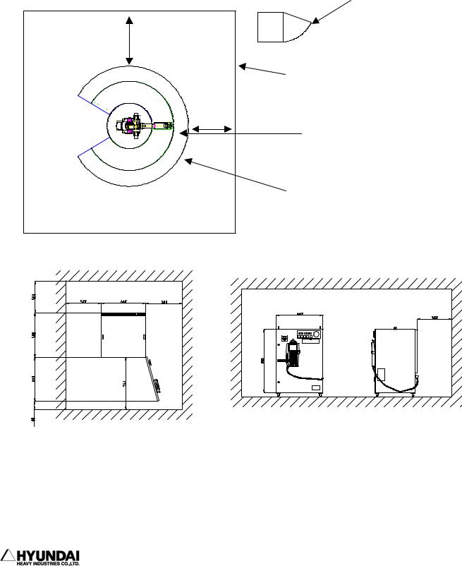
1.1.6.4 Space for robot installation
Install robot manipulator, controller, other peripheral equipment. Be sure that there are sufficient rooms for maintenance on the manipulator, controller and other peripheral equipment. Install robot manipulator and controller as per the guideline as described in the figure below.
Hi4 |
Door |
controller |
|
1000mm
Enclosure
1000mm
Working envelope of manipulator
Maximum working envelope of manipulator including Tool or Workpiece.
Install controller in order that maintenance work can be easily performed when door open. Secure the maintenance free area whenever robot need to be maintained. Dimension of controller as specified in the above figure can be changed according to the kind of controller.
--------------------------------------------------------------------------------
1 - 14

1. Safety, Operation Panel, Teach Pendant (1) Safety
------------------------------------------------------------------------------------------------
1.1.7. Safety Working Procedures
Safety working procedures must be observed to prevent from any accidents. Safety device or circuit shall not be modified and disregarded by workers or operators at any time.
Be careful of any possible accidents caused by electric shock. All normal operations in automatic mode must be executed outside safety fence. Prior to operation, be sure there are no personnel within the manipulator's working envelope.
!1.1.7.1. Safety measure for robot operation
(1)Have the robot system operators, any workers who is possible to operate or any superintendents attend the training courses held by Hyundai in order that they can have a good command of safety and robot functions. Do not allow workers who do not attend the training courses to operate the robot.
(2)Wear safety helmet, safety glass, safety boots during operation.
(3)2workersasateammustworktogether.Oneworkermustsupervisethroughoperation panel while another worker make teaching operation. One worker always must be in a position to push emergency stop button while another worker execute operation work inside or outside the operation space of the robot with sufficient cautions. Furthermore, all the workers must have a good knowledge on escaping route before their operation work.
(4)Supplypower-onaftercertainlyensuringthatthereisnopersonswithinoperating space of the robot.
(5)Do teaching work outside the working envelope of the robot, in principle. However, after motor-off, you may execute work within the working envelope of the robot by hand-carrying key switch or safety plug, which will prevent from automatic operation which can be made by any third parties. Furthermore, pay your special attention to direction of movements which can be made by abnormal or error situation, if any.
--------------------------------------------------------------------------------
1 - 15

1. Safety, Operation Panel, Teach Pendant (1) Safety
------------------------------------------------------------------------------------------------
(6) Superintendent must observe the followings;
-Stay at the place where he can see robot entirely and concentrate on his job of superintendence.
-Press emergency stop button if there is any abnormal situation.
-keep any people other than the workers who are working for the robot, away from the working envelope of the robot.
(7)In manual mode, teaching must be made not more than the speed of 250mm/sec.
(8)Do the teaching work by laying of "Under Teaching Operation" signboard all the time.
(9)Any workers who enter inside safety fence must unplug and bring the safety plug into the safety fence.
(10)Do not use any equipment which can produce any noise around the place for teaching work.
(11)Do not operate teach pendant by feeling of hand only but operate it by watching the keypads clearly.
!(12) Pay your careful attention to the movement of the robot. Do not work for the robot under the situation the robot is behind yourself.
(13)Watch your step during your teaching work. In case of high ground teaching work more than 2 meters, start your work after securing the sufficient safety space for workers' step-on.
!(14) Followings are the counter measures which must be taken in case of any abnormal situations
-Press emergency stop button immediately after finding any abnormal operation.
-When you want to check the abnormal situation after emergency stop, confirm the stop status of the robot without any fail.
-Robot can stop automatically due to the abnormal power supply. In this case, check
--------------------------------------------------------------------------------
1 - 16

1. Safety, Operation Panel, Teach Pendant (1) Safety
------------------------------------------------------------------------------------------------
first the stop status of the robot and further investigate the cause to execute relevant measure.
-When the emergency stop function does not work, disconnect the power supply immediately and further investigate the cause to execute relevant measure.
-No one who have no operation and maintenance training provided by Hyundai can be authorized to do the investigation of the cause for abnormal situations. In the event of emergency stop, re-start of motor must be made by the defined procedure only after implementing the measure as a result of the detailed investigation to the cause for abnormal operation.
(15)Prepare relevant working manual on robot operation, working method and the required action for abnormal situations according to the installation places and working contents. Proceed with any works as per the relevant working manual.
(16)Precautions during the stop of robot
Do not access to the robot even though the robot is just stopping. There can be a serious accident caused by sudden movement of robot when you access to the stopped robot without any precaution. Followings are the cases that the robot is under the stop status.
No. |
Robot Situation |
Motor |
Accessible or not |
|
|
|
|
|
|
|
|
1 |
Temporary stopping |
ON |
Not accessible |
(small problem,Temporary stop switch) |
|||
|
|
|
|
2 |
Emergency stopping (Serious problem, Emergency stop |
OFF |
Accessible |
|
switch, safety gate) |
|
|
|
|
|
|
3 |
Input Signal Stand-by from peripheral equipment (START |
ON |
Not accessible |
|
INTERLOCK) |
|
|
|
|
|
|
4 |
During Playback completion |
ON |
Not accessible |
|
|
|
|
5 |
During Stand-by |
ON |
Not accessible |
|
|
|
|
Always, pay your careful attention to the unexpected movement of the robot even though it is the above situation which you can enter to working envelope. Entering to the working envelope of the robot without any preparation for unexpected emergency situation must be prohibited at any time.
--------------------------------------------------------------------------------
1 - 17

1. Safety, Operation Panel, Teach Pendant (1) Safety
------------------------------------------------------------------------------------------------
Note) As specified in the above table, in case of temporary stopping, access to the working envelope of the robot is not allowed. However, when you try to get inside the working envelope of the robot in order to make corrections for minor problems such as nozzle contact and arc trouble, enter the working envelope of robot only after following the same method as you enter the working envelope for teaching work.
(17) When you finish the operation work of robot, do cleaning work for the area inside the safety fence to remove any tools, oil or foreign material which left on the floor. Contamination of working area by oil and any left tools can cause slippery and personal injury. Please do your cleaning and proper arrangement regularly,
!1.1.7.2 Safety Measure for Robot Try-out
Engineering error, Teaching error and manufacturing defects on the total system including teaching program, jig and sequence etc. can be found during try-out of the robot. Therefore, do your try-out operation taking your due consideration into the safety matter. Safety related accident can took place due to the combined reasons.
(1)Check first the functions of signals and buttons such as emergency stop button and stop button etc. before robot operation and further check error detection function. Checking of all the signals for stopping the robot is the most important thing. When you can foresee the possible accident previously, the most important thing is to stop the robot.
(2)For the try-out of robot, operate in the lower speed of 20% 30% and further check movement more than 1 cycle repeatedly. When you find any problems, modify them immediately. Afterwards, make speed-up by the order of first 50%, second 75% and final 100% and further check movement more than 1 cycle for each speed set-up respectively. When you make speed set-up of high speed at the beginning, the unexpected accident can take place.
(3)You can not foresee any problems to be made during try-out. Do not enter inside
--------------------------------------------------------------------------------
1 - 18
 Loading...