


HD78

Body Electrical
System
General
Generals ....................................................... BE - 3
Specifications ............................................... BE - 6
Diagnosis ...................................................... BE - 7
Fuses and Relays
Component Location .................................... BE - 12
Components ................................................. BE - 14
Relay
Inspection ................................................ BE - 16
Fuse
Inspection ................................................ BE - 17
Indicators and Gauges
Instrument Cluster
Components ........................................... BE - 18
Circuit Diagram ....................................... BE - 20
Connector Configuration ........................ BE - 23
Fuel Gauge
Inspection ................................................ BE - 25
Water Temperature Gauge
Inspection ................................................ BE - 26
Tachometer
Inspection ................................................ BE - 27
Speedometer
Inspection ................................................ BE - 28
Door Warning Indicator
Inspection ................................................ BE - 29
Seat Belt Warning Indicator
Inspection ................................................ BE - 30
Parking Brake Switch
Inspection ................................................ BE - 31
Tilting Lock Sensor
Inspection ................................................ BE - 32
Hazard Switch
Inspection ................................................ BE - 33
Working Lamp Switch
Inspection ................................................ BE - 34
Front/Rear Fog Lamp Switch
Inspection ................................................ BE - 35
Idle Adjust Switch
Inspection ................................................ BE - 36
Multi Function Switch
Components ................................................. BE - 37
Inspection ..................................................... BE - 38
Windshield Wiper/ Washer
Component Location .................................... BE - 40
Windshield Wiper/Washer
Removal .................................................. BE - 41
Inspection ................................................ BE - 42
Circuit Diagram ....................................... BE - 42
Connector ............................................... BE - 42
Power Windows
Power Window Motor
Connector Configurations ...................... BE - 43
Circuit Diagram ....................................... BE - 43
Inspection ................................................ BE - 43
Power Window Switch
Inspection ................................................ BE - 44
Circuit Diagram ....................................... BE - 45
Lighting System
Components ................................................. BE - 46
Head Lamp
Replacement........................................... BE - 47
Inspection ................................................ BE - 48
Adjustment .............................................. BE - 49
Turn Signal Lamp
Replacement........................................... BE - 51
Room Lamp
Replacement........................................... BE - 52
Fog Lamp
Replacement........................................... BE - 53
Inspection ................................................ BE - 53
Adjustment .............................................. BE - 54
Head Lamp Leveling Device
Description.................................................... BE - 56
Components ................................................. BE - 56
Part Circuit Diagrams ................................... BE - 57
Keyless Entry System
Components ................................................. BE - 59
Description.................................................... BE - 60
Operation ...................................................... BE - 61
Inspection ..................................................... BE - 71
Adjustment .................................................... BE - 72
Specification ................................................. BE - 72
Door Lock Actuator
Inspection ................................................ BE - 73

Digital Tachograph
Specifications ............................................... BE - 74
Description.................................................... BE - 74
Components ................................................. BE - 75
Part Circuit Diaram ....................................... BE - 76
Replacement ................................................ BE - 77
DTC Chart ..................................................... BE - 77
Audio System
Audio Unit
Components ........................................... BE - 78
Replacement........................................... BE - 80
Cleaning ................................................. BE - 80
Speaker
Replacement........................................... BE - 81
Inspection ................................................ BE - 82
Horns
Horns
Component Location .............................. BE - 83
Replacement........................................... BE - 84
Inspection ................................................ BE - 84
Electronic Time And Alarm Control System
Components ................................................. BE - 85
Circuit Diagram ............................................. BE - 86
Connector ..................................................... BE - 88
Specifications ............................................... BE - 90
Generals ....................................................... BE - 91
Operating Principle ...................................... BE - 91
General
Generals
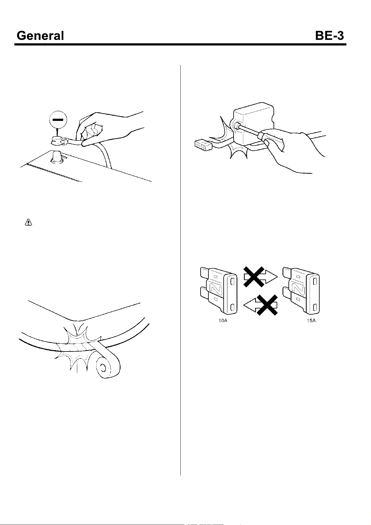
1. For servicing the electric system, the battery (-)
terminal should be disconnected first.
KMTBE5001A
CAUTION
Before connecting or disconnecting the (-)
terminal, all lamp switches should be turn "OFF".
(Otherwise, the semiconductor devices would be
damaged)
2. If the harness can be contacted with a sharpened
part or corner, wrap those portion with a tape for
preventing the harness from being damaged.
3. When the parts are installed at the vehicle, be careful
that the wiring harness is not torn off or damaged.
KMTBE5003A
4. When the fuse is burn-out, replace it with a new one
of rated ampere. If one of higher than nominal
capacity is used, the electric parts may be damaged
or fire may be occurred.
KMTBE5002A
KMTBE5004A
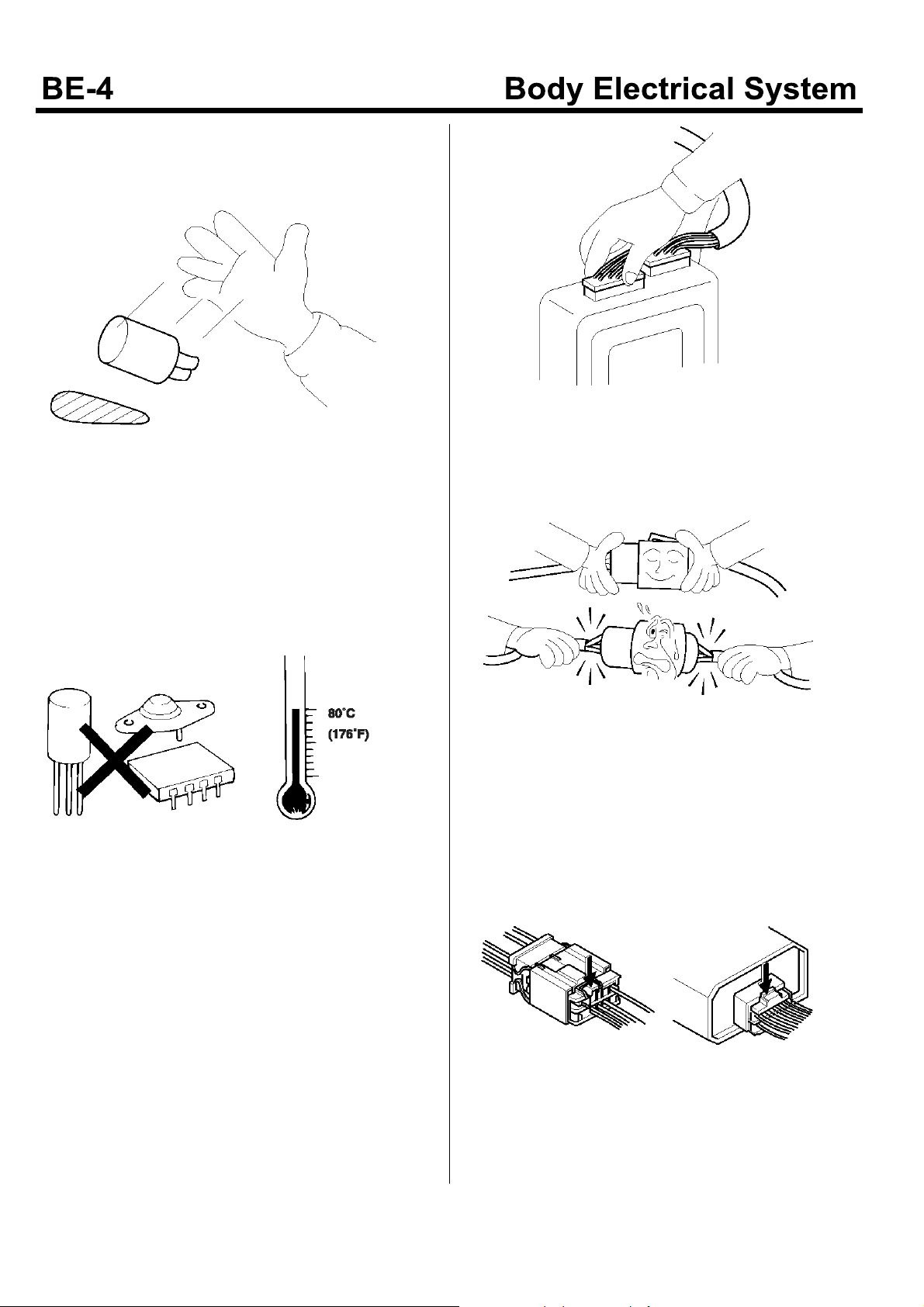
5. Be careful that the sensors or the relays are not
shocked. Do not drop them down to the floor. Do not
throw them recklessly.
KMTBE5005A
6. As the electric components used for computer or
relay are easily damaged by a heat, if the service is
performed under the high temperature over 80°C,
these electric components should be removed in
advance.
KMTBE5007A
8. When disconnecting the harness, hold the connector
and pull it. Do not pull the harness to disconnect it.
KMTBE5006A
7. As the loosened connector may be the causes of
troubles, connecting of the connector should be
ensured.
KMTBE5008A
9. When disconnect the connector having a locking
device, press the lock to the arrow direction as shown
in the following figure to remove the connector.
KMTBE5009A
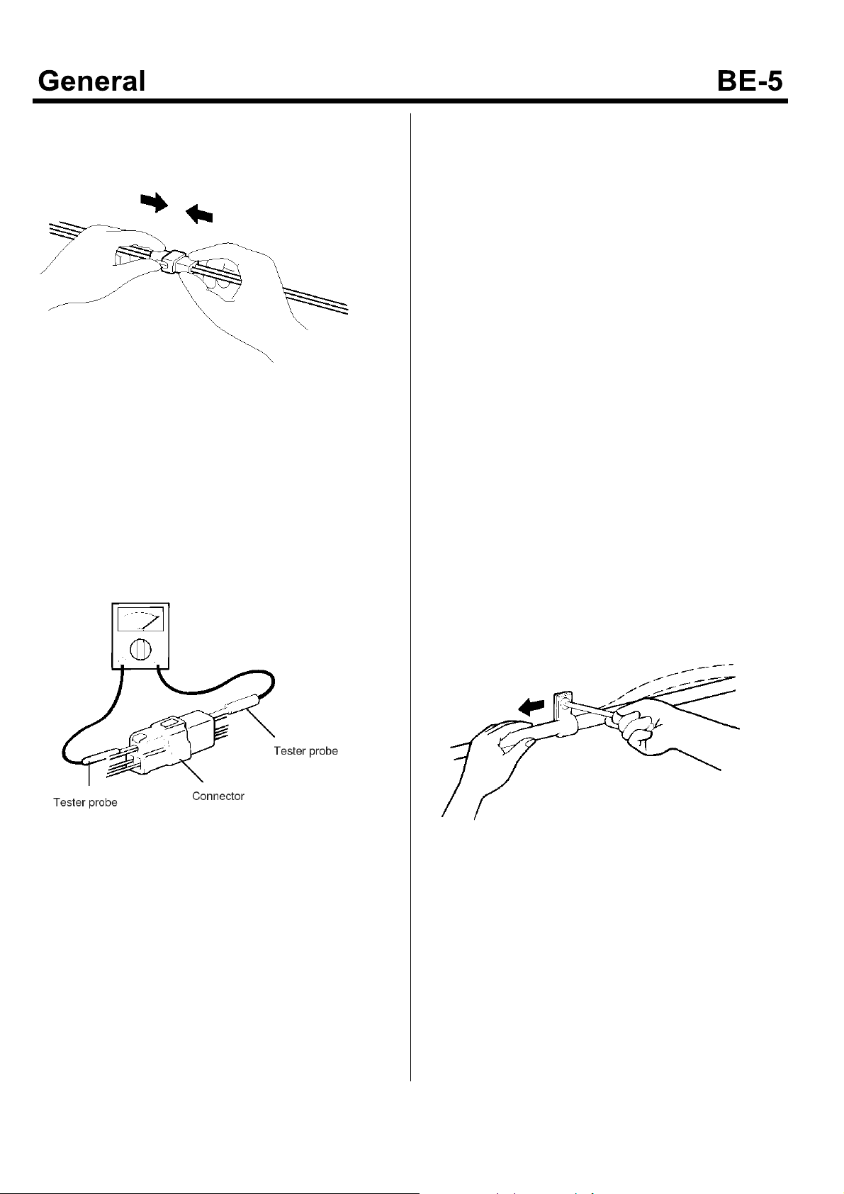
10.When connecting the connector, insert the connector
until "Tag" sound can be heard.
KMTBE5010A
11.When checking the electric current or voltage at the
connector terminal using a circuit tester, insert the
tester probe from the harness side. When the
connector is the sealed type, insert the probe through
the hole in the wiring rubber cap. At that time, be
careful that the insulating of the wire is not damaged.
Insert the probe until it contacts with the connector
terminal completely.
Inspection of Cable and Wire
1. Check that the connecting portion is loosened or
rusted.
2. Check that the terminal or wire is corroded by the
battery electrolyte.
3. Check that the circuit of the terminal or the wire is
opened.
4. Check that the wire is properly insulated or the
sheath is damaged, cracked or deteriorated.
5. Check that the conductive material of the wire
contacts with metal parts of other components (body
or other parts).
6. Check that the fixing bolt is electrically connected to
the body completely.
7. Check that the wiring is properly performed.
8. Fix the wiring firmly to preventing it from contacting
with the sharpened parts of body or the portions
making a high temperature (exhaust manifold or
exhaust pipe).
9. The wire should be fixed with enough clearance from
the fan pulley, the fan belt and other rotating parts or
vibrating parts.
10.Thewiringbetweenthebody,thefixedpart,andthe
engine, the vibrating part, should be fixed after
distancing or slacking the wire somewhat.
EMTBE5007A
KMTBE5012A
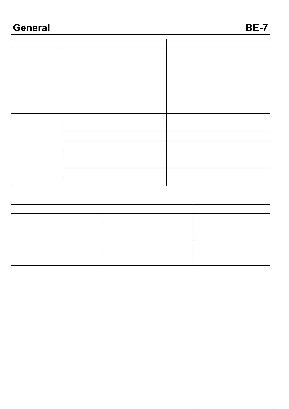
Specifications
Item Specifications
Indicator and Gauge
(Except D4GA engine)
Indicator and gauge
(D4GA engine)
Multi function switch Nominal voltage DC 24V
Fuel gauge type
Unit type
Water temperature gauge type
Unit type
Tachometer type
Sensor type
Speedometer type Pulse type
Odometer type Gear eddy current type
Indicator type Bulb type
Fuel gauge type Stepper motor
Water temperature gauge Stepper motor(M iddle fixing type)
Tachometer type Stepper motor
Speedometer type Stepper motor
Indicator type LED type
Operating tempera ture range -30~+80°C
Nominal load
Dimmer and Passing switch
Lightening switch
Turn signal lam p switch
Wiper switch
Washer switch
Exhaust brake
Change of volume
Cross coil type(Scale fixing type)
Variable resistor type
Cross coil type (Middle fixing type)
Thermistor typ e
Cross coil type
Moving coil type
0.12A (R e lay load)
0.12A (R e lay load)
21W x 2+1.7W (Lamp load)
0.12A (R e lay load)
1.75A (Motor load)
0.8A (Coil load)
Max 10mA
Insulating resistance 1M or more at 500MV
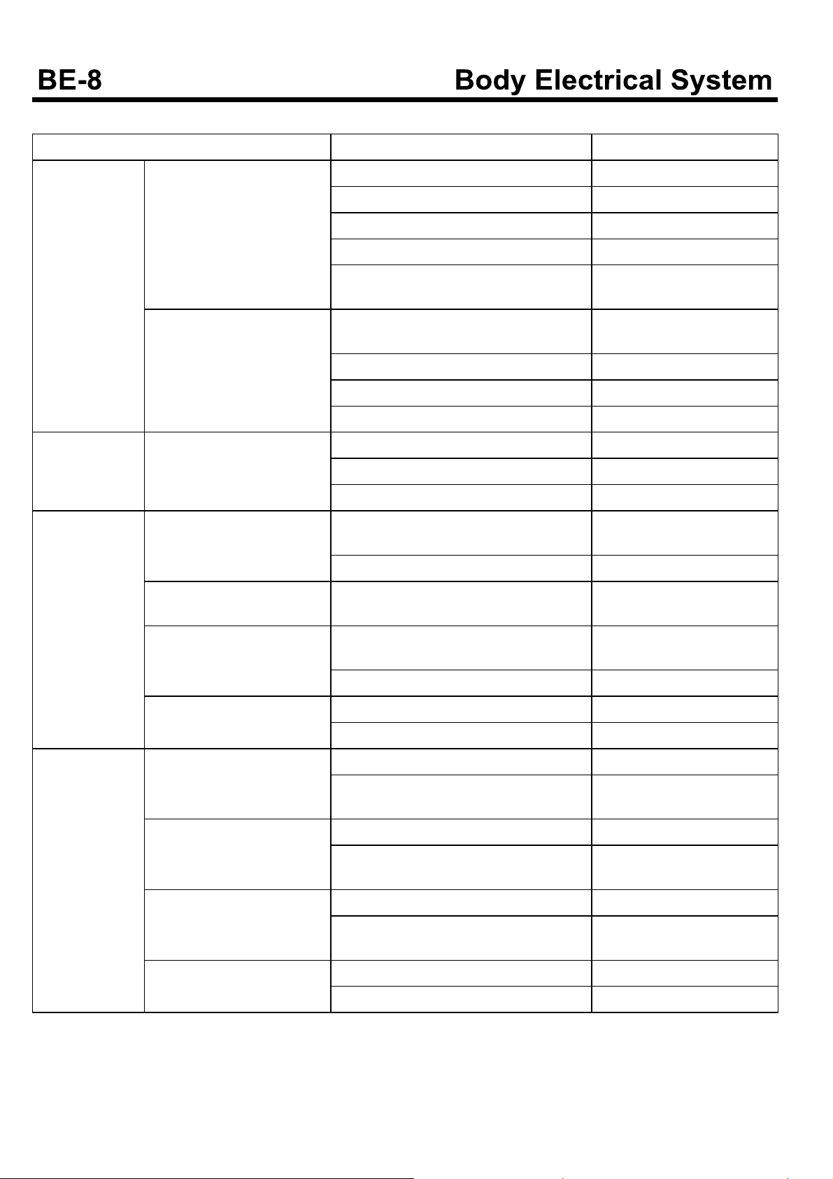
Wind shield wiper/Washer
Power window Power window motor
Wiper motor type Ferrite magnetic type
Washer motor type Ferrite magnetic type
Washer tank capacity 2.8 or more
Nominal voltage
Operating tempera ture range
Power window switch
Nominal voltage
Operating tempera ture range
Power window switch nominal load current
Power window switch max load current
Window lock switch nominal load current (Driver's seat)
Window lock switch max load current (Driver's
seat)
DC 24V
-30~+70°C
DC 24V
-40~+100°C
4A (Switch current)
10A (Flowing current)
4A (Switch current)
10A (Flowing current)
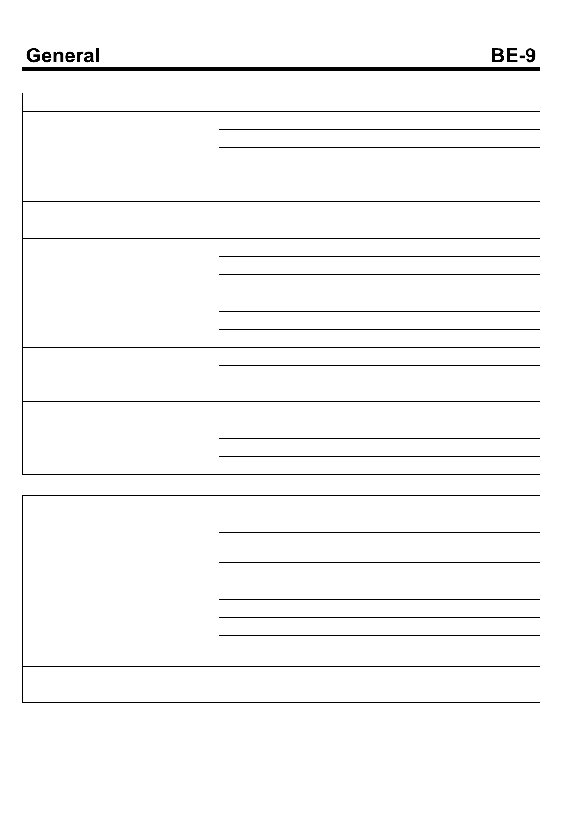
Item Specifications
Lightening system Lamp capacity
Head lamp (Up/Down)
Turn lamp
Position lamp
Tail / Brake lamp
Room lamp
Fog lamp
Back up lamp
License plate lamp
Luminescent lamp
Horn Type Flat type
Nominal voltage DC 24V
Frequency 415±20Hz
Decibel 100~112 dB
Cigar lighter Type Bimetal Type
Nominal voltage DC 24V
Nominal current 5A
Returning time after pressing the plug 13±5sec.
75W70W
21W
5W
5/21W
10W
70W
21W
12W
10W
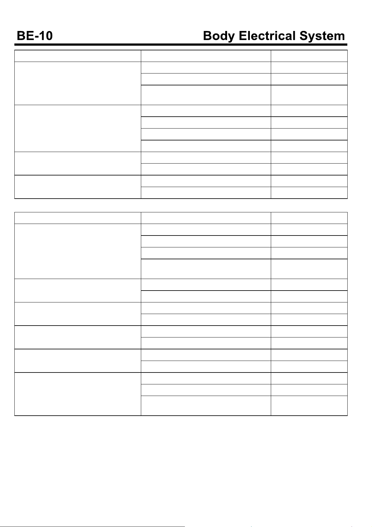
Diagnosis
Ignition Switch
Symptom Causes Remedy
When turning the ignition switch to the START, the starter is not working.
The ignition switch is faulty. Replace
The battery is discharged. Charge
The starter relay or the starter is faulty. Replace
The starter fuse is short. Replace
The wiring circuit is opened or the contact is faulty.
Repair
Lighting System
Symptom Causes Remedy
General Light When turning the switch ON,
the lamp is not lightened.
Lamp is dark. Thelifetimeofbulbisoverorthebulbis
Head Lamp The head lamp is not workin-g.Thelampswitchisfaulty. Replace
Turn, Hazard Lamp
The lamp is not blinking. Theswitchofturnoremergencylampis
Thebulbisshort. Replace
The battery is discharged. Charge
The switch is faulty. Replace
The fuse is short. Replace
The wiring circuit is opened or the contact is faulty.
faulty.
The battery is discharged. Charge
The switch does not properly contact. Replace
The wiring or terminal is faulty in contact. Repair
Thedimmerswitchisfaulty. Replace
Theheadlamprelayisfaulty. Replace
faulty.
The blinking relay is faulty. Replace
Repair
Replace
Replace
The lamp is lightening conti nually.
The blinking interval is too long.
The blinking interval is too short.
Other Lamp The brake lamp is not lighte-
ning.
The tail lamp, position lamp
or the number plate lamp is
not lightening.
Back up lamp is not lightening.
The fog lamp is not lightenin-g.The fog lamp switch is faulty. Replace
The blinking relay is faulty. Replace
The power of the bulb is lower than nominal.
The blinking relay is faulty. Replace
Thebulbisshort. Replace
The blinking relay is faulty. Replace
The brake lamp switch is faulty. Replace
The brake lamp switch is not installed properly.
The light switch is faulty. Replace
The tail lam p relay is faulty. Replace
Back up lamp switch is faulty. Replace
TheBackuplampswitchisnotinstalled
properly.
The fog lamp relay is faulty. Replace
Replace
Repair
Repair
Meter and Gauge
Symptom Causes Remedy
The speedometer does not work. The speed sensor is faulty. Replace
The fuse is opened or blow. Replace
The speedometer is faulty. Replace
The needle of the speedometer is unstable. The speed sensor is faulty. Replace
The speedometer is faulty. Replace
The tolerance of the speedom eter is too large.
The tachometer does not work. The tachometer sensor is faulty. Replace
The needle of the tachometer is unstable, or
its tolerance is too large.
The coolant temperature gauge does not work.
The needle of the coolant temperature gauge is unstable, or its tolerance is too large.
Thetiresizeisnotproper. Replace
The speedometer is faulty. Replace
The tachometer is faulty. Replace
The fuse is short. Replace
The tachometer sensor is faulty. Replace
The tachometer is faulty. Replace
The wiring is faulty Replace
The fuse is short. Replace
The coolant temperature gauge is faulty. Replace
The coolant temperature gauge unit is faulty. Replace
The coolant temperature gauge is faulty. Replace
The coolant temperature gauge unit is faulty. Replace
The wiring is faulty. Repair
The thermostat is faulty. Replace
Indicating and Warning Lamp System
Symptom Causes Remedy
When switch is ON, each unit is working but
the indicating lamp is not lightened.
When the parking brake knob is pulled, the
brake lamp is not lightened.
After releasing the parking brake, the brake
lamp is not off.
Thebulbisopen. Replace
The wiring circuit is opened, or it contact is faulty.
The switch is working abnorm ally. Replace
Thebulbisshort. Replace
The spring brake switch is faulty. Replace
The fuse is short. Replace
The wiring circuit is opened, or it contact is faulty.
The spring brake switch is faulty. Replace
The wiring is faulty. Repair
Repair
Repair
Symptom Causes Remedy
The brake lamp does not work. Thebulbisshort. Replace
The fuse is short. Replace
The wiring circuit is opened, or it contact is faulty.
During working of engine, the oil warning lamp turns on.
During working of engine, the charging warning lamp turns on.
The overheat warning lamp turns on. The coolant water is not enough. Adjust
Theengineoilpressureistoolow. Adjust
The engine oil is leak or it level is too low. Adjust
The oil pressure switch is faulty. Replace
The oil filter is clogged. Replace element
The V-belt is sagging or broken. Replace or adjust
The alternator is faulty. Repair
The overheat sensor is faulty. Replace
Repair
Wiper
Symptom Causes Remedy
The wiper does not work. The wiper motor is faulty. Replace
The wiper switch is faulty. Replace
The fuse is short. Replace
The wiring circuit is opened, or it contact is faulty.
Repair
Thewipercannotstop. The wiper switch is faulty. Replace
The wiper motor is faulty. Replace
The wiper does not perform the intermittent
operation.
The blade does not stop on proper position. The wiper link is positioned abnormally. Adjust
The wiping condition is faulty. The blade is faulty. Replace
During working, the wiper makes an abnormal noise.
The ETACS is faulty. Replace
The wiper switch is faulty. Replace
The wiper motor is faulty. Replace
The wiper arm is faulty. Replace
The wiper motor is faulty. Replace
The blade is faulty Replace
The wiper link or the wiper arm contact is faulty.
Repair
Washer System
Symptom Causes Remedy
The washer motor does not work. The washer motor or pump is faulty. Replace
The washer switch is faulty. Replace
The fuse is short. Replace
The wiring circuit is opened, or it contact is faulty.
The spaying amount of the washer liquid is too small.
The washer liquid is not sprayed. The jointing of hose is faulty. Repair
The hose is twisted. Adjust
The washer nozzle is clogged. Clear
The washer motor or pump is faulty. Replace
The washer nozzle is clogged. Clear
The washer motor or pump is faulty. Replace
The level of washer liquid is too low Refill
Repair
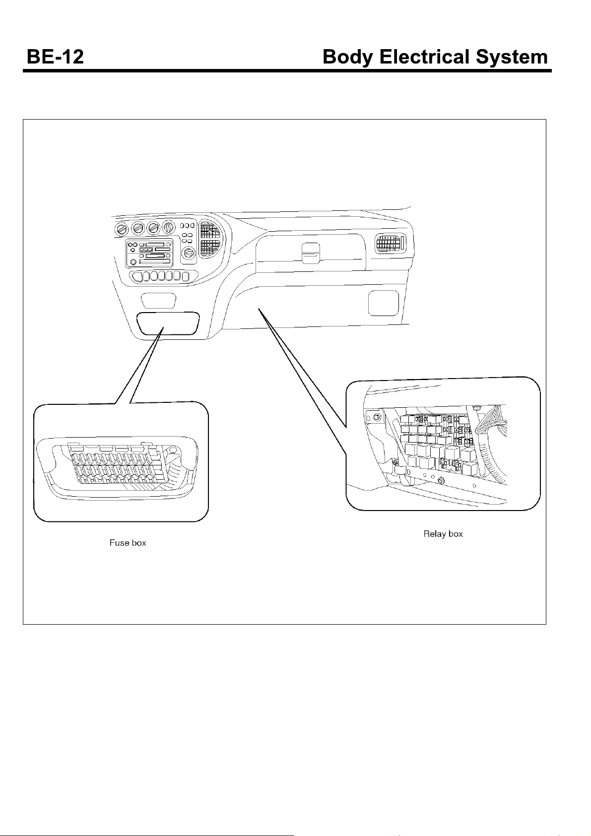
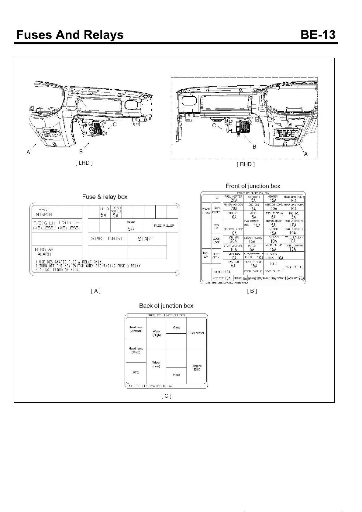
Fuses And Relays
Component Location (Except D4GA engine)
EMTBE5008A
Component (D4GA engine)
SUDBEA0053L
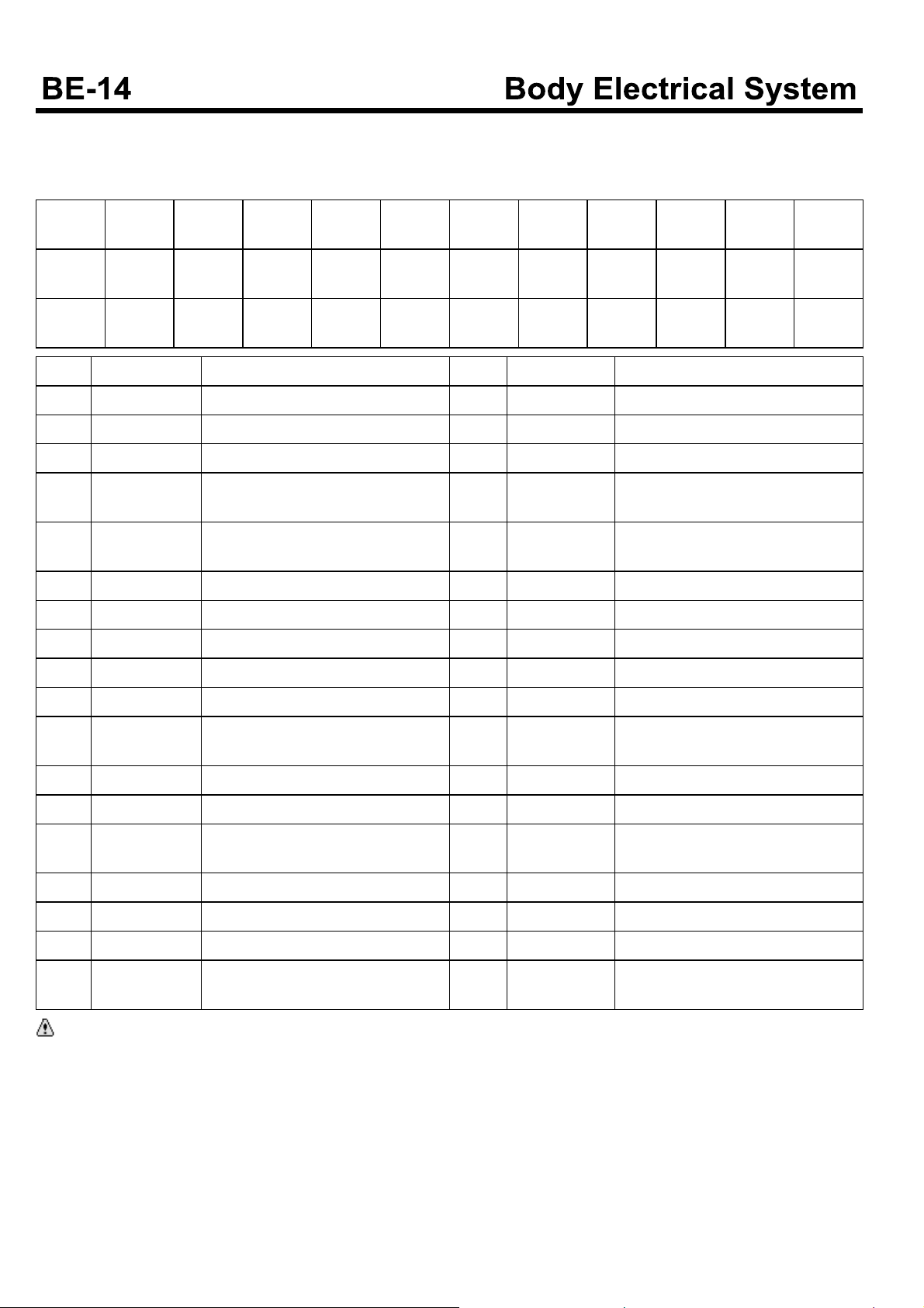
Component(Fuse)
Except D4GA engine
Fuse box
1
15A
13
20A
25
10A
Fuse Amperages Circuit protected Fuse Amperages Circuit protected
1 15A Working lamp 19 15A Outside mirror defogger
2 5A Head lamp relay 20 - -
3 10A Blower and A/C control 21 20A Fuel heater
4 10A
5 15A Wiper and washer 23 10A
6 5A ABS control(ECU) 24 15A Starting
7 5A PTO 25 10A Head lamp(LOW)_LH
8 - - 26 10A Head lamp(LOW)_RH
2
5A
14
10A
26
10A
3
10A
15
10A
27
10A
Exhaust brake, tachograph(EC),
Cold start switch
4
10A
16
10A
28
10A
5
15A
17
10A
29
10A
5A
18
15A
30
10A
6
7
5A
19
15A
31
10A
22 10A -
8
10A
20
20A
32
5A
10A
20A
15A
9
21
33
Tachograph, ETACS, audio, instrument cluster, room lamp
10
15A
22
10A
34
15A
11
10A
23
10A
35
10A
12
10A
24
15A
36
15A
9 10A Sub start 27 10A Head lamp(HIGH)_LH
10 - - 28 10A Head lamp(HIGH)_RH
11 10A
12 10A ETACS, Instrument cluster 30 10A RH Tail lamp
13 20A Power window 31 10A Front fog lamp
14 10A
15 10A Cab tilting switch, hazard lamps 33 15A Condenser fan relay, A/C relay
16 10A RR FOG lamp 34 15A Heater blower
17 10A Power door lock(unlock) 35 10A 12V converter, ETACS
18 15A ABS control(valve) 36 15A
CAUTION
Use the designated fuse only.
Vehicle speed sensor, Back up lamps
Stop lamp, horn, data link connector
29 10A LH Tail lamp
32 5A Engine ECU
Instrument cluster, audio, cigarette
lighter, clock
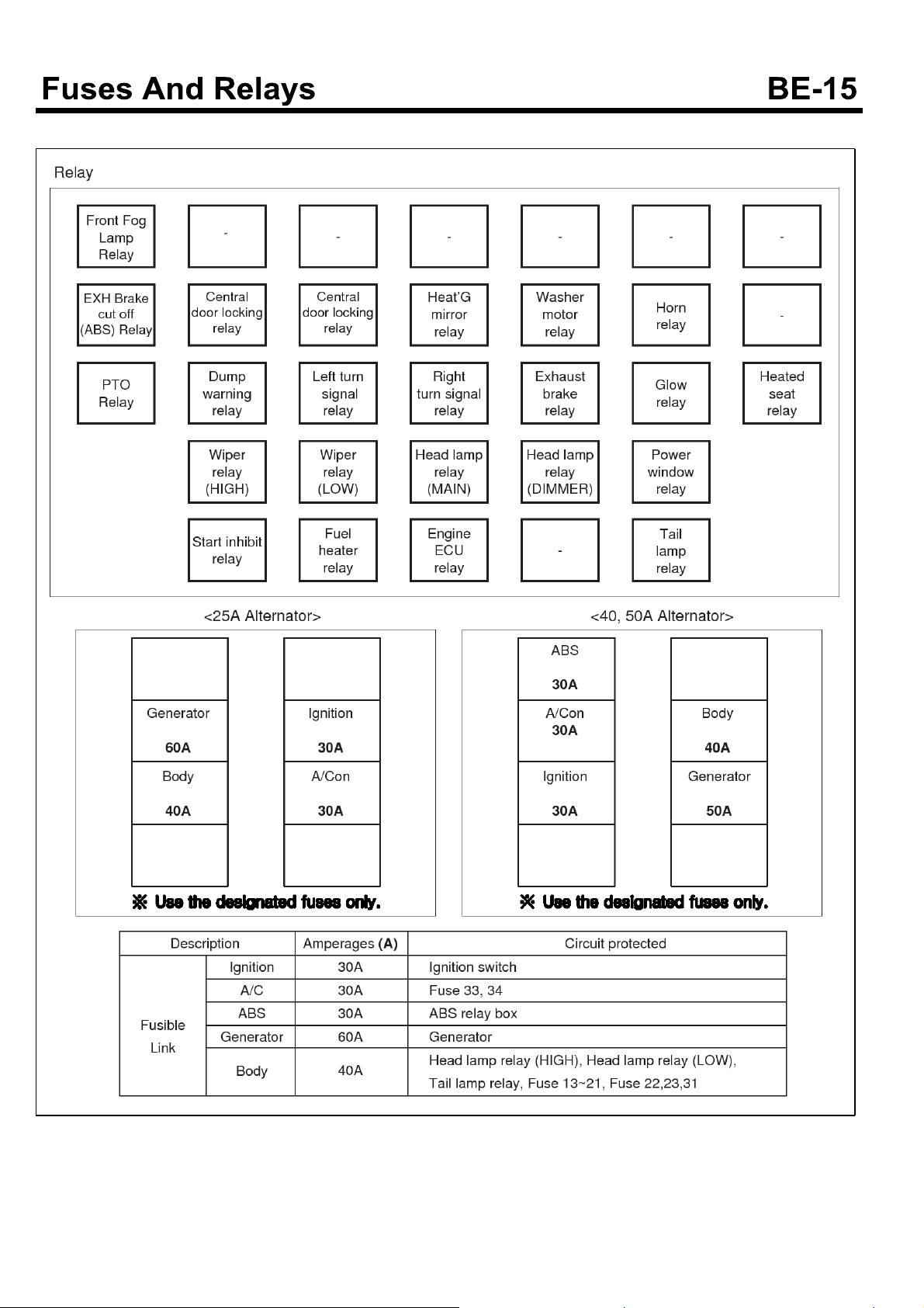
Components(Relay, Fuse blink)
EMTBE5009A
Relay
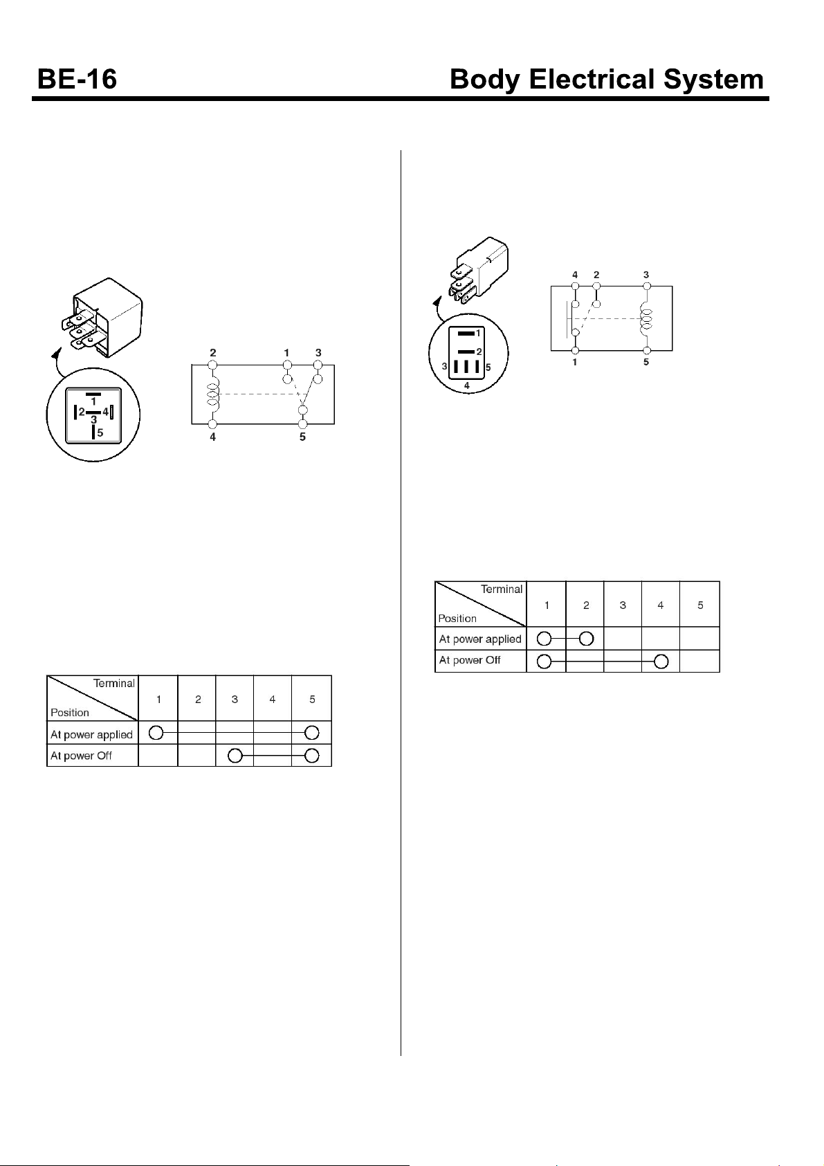
Inspection
Type A relay
1. When an electric power is applied between the power
relay terminal No.2 and No.4, check that there is an
electric current between the term inal No.1 and No.5.
KMTBE5015A
2. When the electric power applied between the power
relay terminal No.2 and No.4 is off, check that there
is an electric current between the terminal No.1 and
No.5.
Type B relay
1. When an electric power is applied between the power
relay terminal No.3 and No.5, check that there is an
electric current between the terminal No.1 and No.2.
KMTBE5016A
2. When the electric power applied between the power
relay terminal No.3 and No.5 is off, check that there
is an electric current between the terminal No.1 and
No.4.
EMTBE5010A
EMTBE5011A
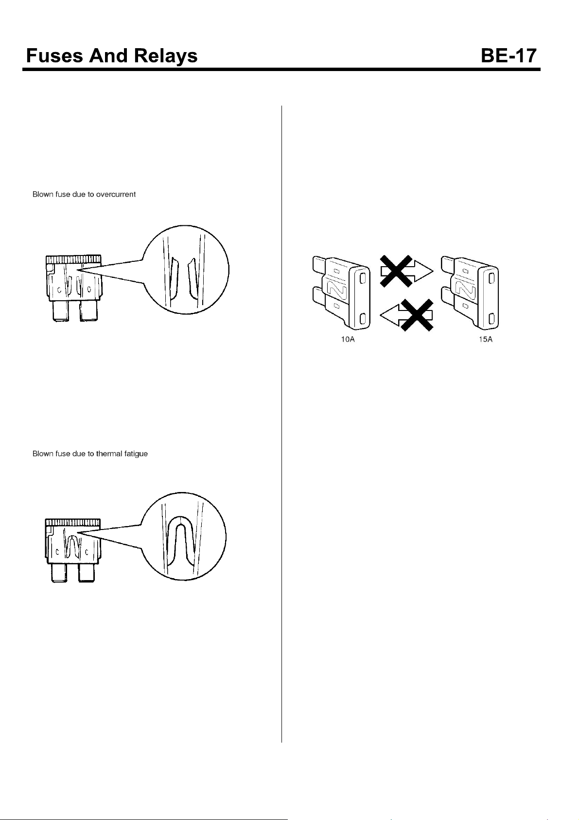
Fuse
Inspection
1. When a fuse is burnt-out, check that there is any
opened or abnorm al component before replacing the
fuse. After replacing the opened or abnormal parts,
install a new fuse of the same ampere.
EMTBE5012A
2. When the fuse is intermittently disconnected, it
means that the fuse does not satisfy the nominal
capacity. If this fuse is used for a long time, it causes
a trouble. At this case, replace with a new one of the
nominal ampere.
3. A blade type fuse is identified by the numbered value
in amperes.
If the fuse is burnt-out, be sure to replace a fuse with
thesameampererating.Ifafuseofhighercapacity
than specified is used, parts may be damaged and
the danger of fire also exists.
To remove or insert a fuse, please use the fuse puller
inthefusebox.
KMTBE5004A
EMTBE5013A

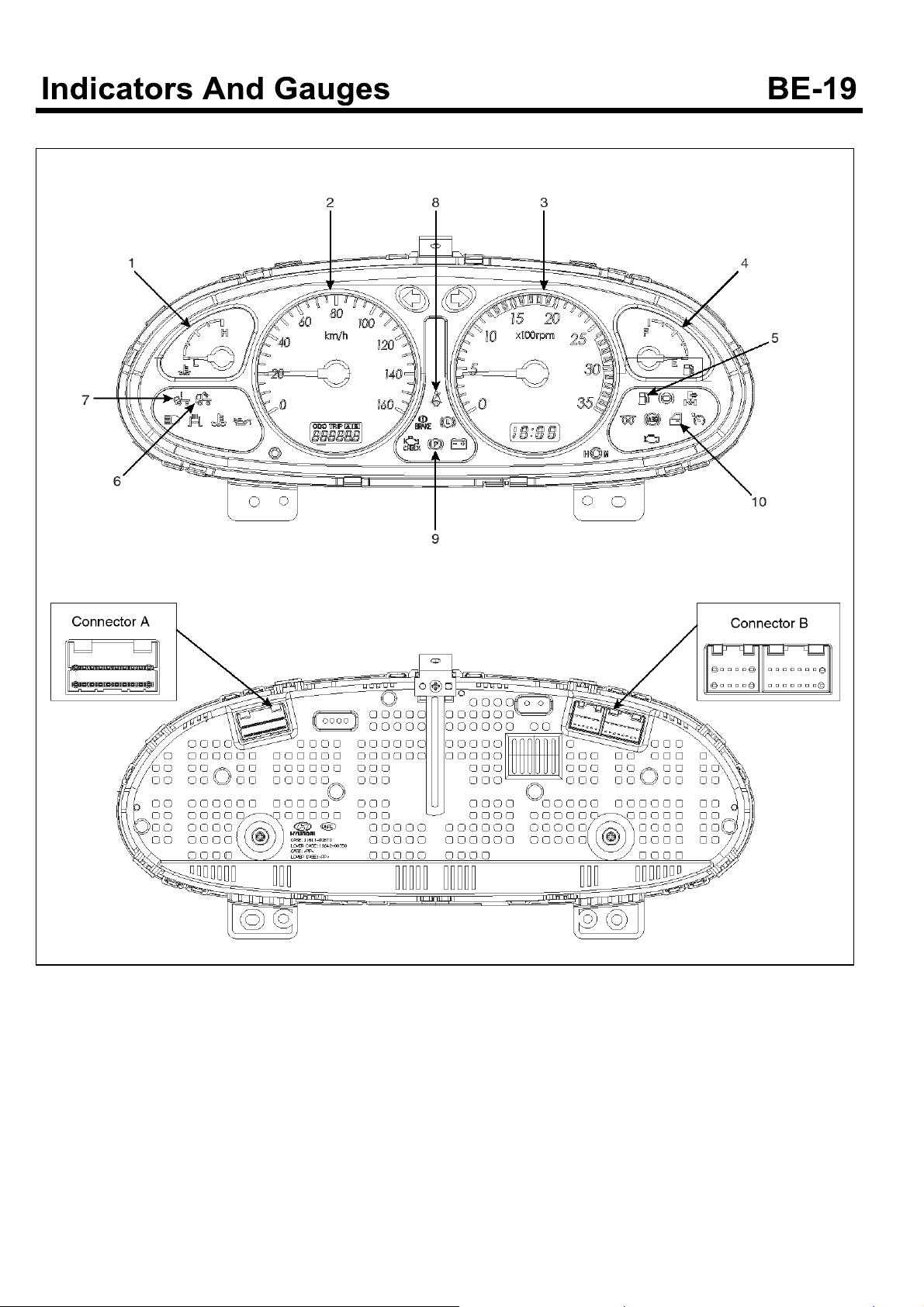
Indicators And Gauges
Instrument Cluster
Components (Except D4GA engine)
1. Temperature gauge
2. Speedometer gauge
3. Tachometer
4. Fuel gauge
5. Fuel warning lamp
6. Working lamp
7. Tilting lock warning lamp
8. Seat belt warning lamp
9. Parking brake warning lamp
10. Door warning lam p
SUDBEA0050L
11. 1st Connector
12. 2nd Connector
13. 3rd Connector
14. 4th Connector
15. Brake oil warning lamp
Components (D4GA engine)
1.Water temperature gauge
2.Speedometer gauge
3.Tachometer
4.Fuel gauge
5. Fuel warning lamp
SUDBEA0051L
6. Working lamp
7. Tilting lock warning lamp
8. Seat belt warning lamp
9. Parking brake warning lamp
10. Door warning lamp
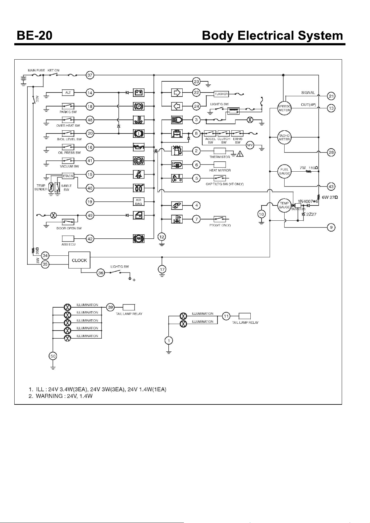
Circuit Diagram (Mechanical engine)
EMTBE5002A
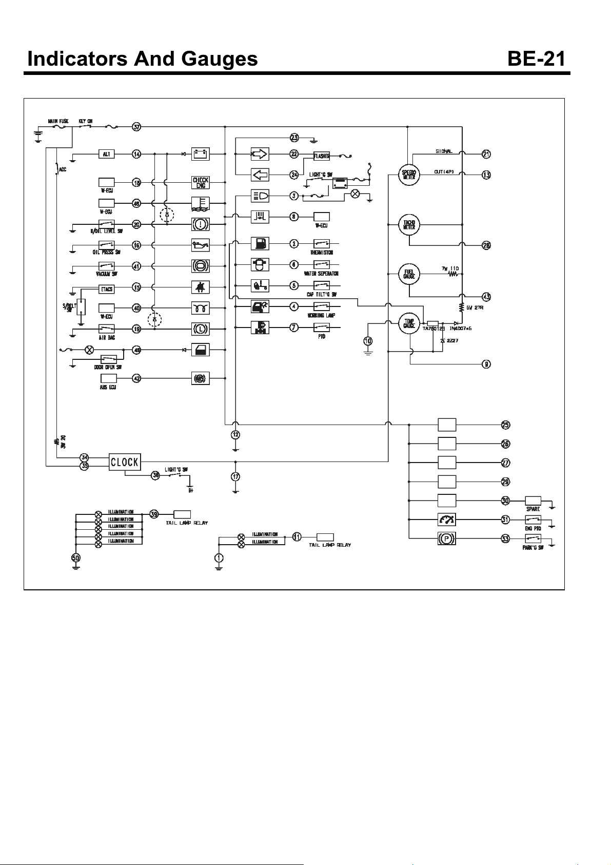
Circuit Diagram (D4DD engine)
SUDBEA0054L
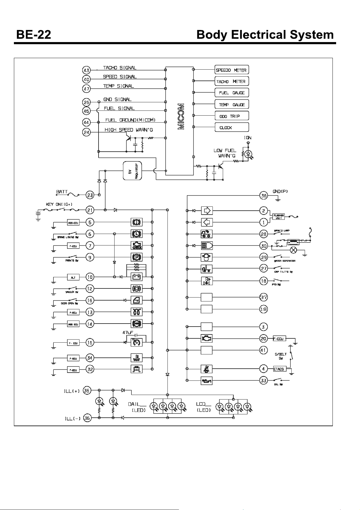
Circuit Diagram (D4GA engine)
SUDBEA0003L
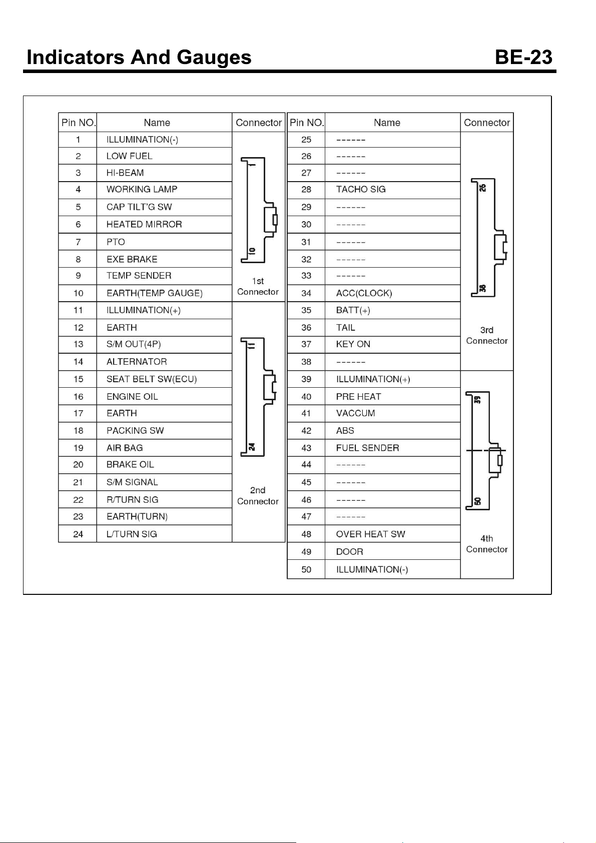
Connector Configurations (Except D4GA engine)
EMTBE5014A
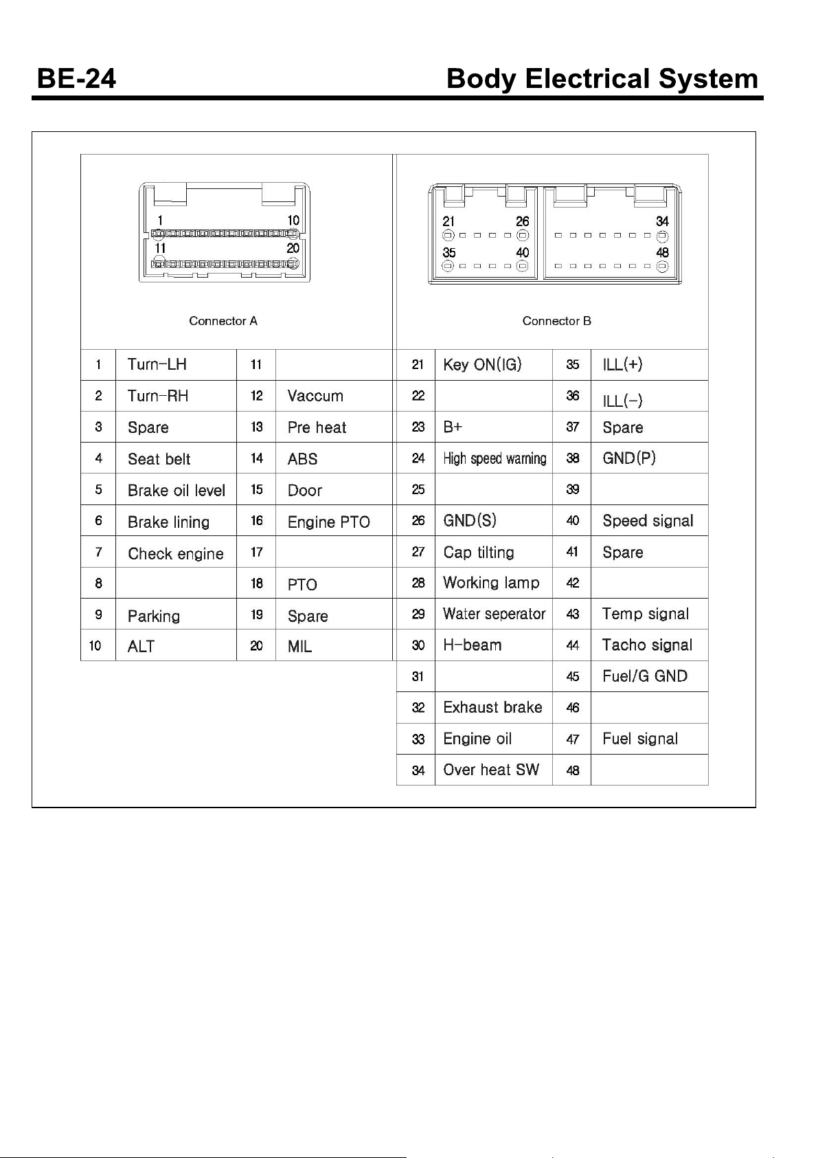
Connector Configurations (D4GA engine)
SUDBEA0004L
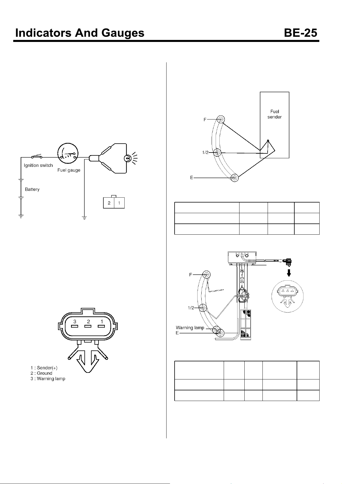
Fuel Gauge
Inspection
Inspection of Fuel Gauge
1. Disconnection the fuel sender connector.
2. After connecting the test bulb to the connector of the
harness in serial, and ground it.
3. Turn the ignition switch to the "ON" position.
4. Check that the test bulb is lightened or the needle of
the fuel gauge is slowly moving to the "F" position.
2. Check that the resistor is varying smoothly, when the
float is moving from "F" to "E" position.
Except D4GA engine
EMTBE5017A
Float Position F 1/2 E
Reference R() 4 32 105
Tolerance of R()
±
2
±
5
±
2
EMTBE5015A
5. If the needle of the fuel gauge is not moving, replace
the cluster.
Inspection of Fuel Sender
1. Setting the float to the "F" and "E" positions, measure
the resistor between the terminal No.1 and No.2,
respectively.
EMTBE5016A
D4GA engine
SUDBEA0038L
Float Position S/F 1/2
Warning la-
mp
S/E
Reference R() 7 32 88 105
Tolerance of R()
±
2.5±2.5
±
2.5
±
2.5

Water Temperature Gauge
Inspection
Inspection of water temperature gauge and
water tem perature sensor
1. If it is not satisfied the tolerance, replace the cluster
and water temperature sensor.
Except D4GA engine
Temperature (
C)
Scale Angle (°) -40 -7 34
Tolerance (°) -
Resistor () 120.5 38~23.4 16.6
D4GA engine
Temperature (°C)
Scale Angle (°) -45 -7 25.5
Tolerance (°) - -3,+2 -5,+5
2. The temperature indicating range is 50~123°C.
°
57 85~105 120
±
5
50 85~105 115
-
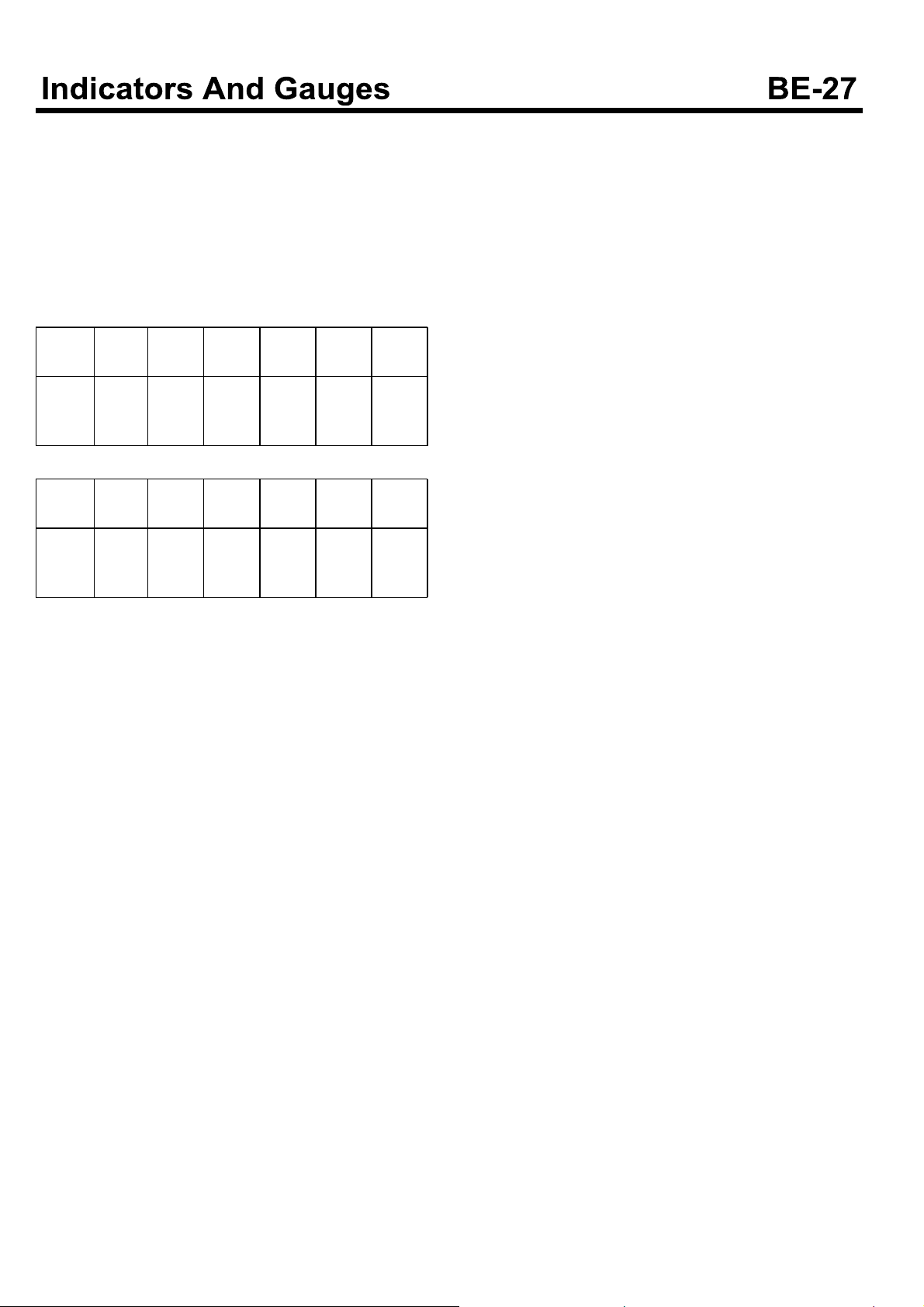
Tachometer
Inspection
1. Connect the tachometer for a tune-up test, start the
engine.
2. By comparing the values indicated by the tester and
the tachometer, if it is over the tolerance, replace the
cluster.
Except D4GA engine
STD
RPM
Tolera-
nce (r-
pm)
D4GA engine
STD
RPM
Tolera-
nce (r-
pm)
3. When performing the test of tachometer, tap the
tachometer to remove the hysteresis.
500 1,000 2,000 3,000 3,500 4,000
±
500 1,000 1,500 2,000 2,500 3,100
±
50
30
±
±
50
50
±
100±150
±
100±100
±
150±150
±
150±150
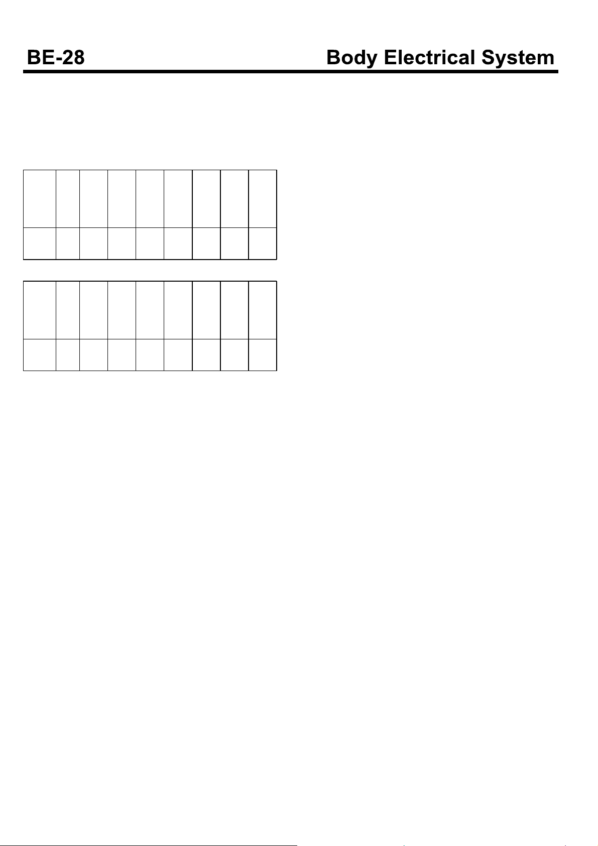
Speedometer
Inspection
1. Using the speedometer tester, check the tolerance of
the speedometer.
Except D4GA engine
STD
Spee-
d(km
20 40 60 80 100 120 140 160
/h)
Tolerance
STD
Spee-
d(km
Tolerance
2. Check that the needle of the speedometer is vibrating
3. When performing the test of speedometer, tap it to
±3+
D4GA engine
20 40 60 80 100 120 140 160
/h)
+
3
0
or the speedometer makes an abnormal noise.
remove the hysteresis.
+
3
0
+
3
0
3.5
0
+
0
+
+
4
0
+
5
5
0
4.5
0
+
0
+
+
5
0
+
5
5
0
+
6
6
0
0
+
5
-
0
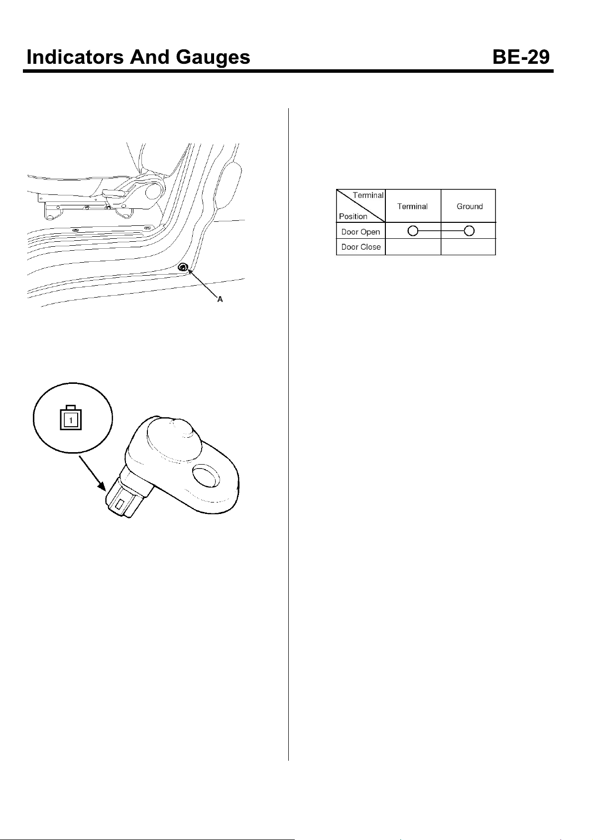
Door Warning Indicator
Inspection
1. Remove the door switch(A).
KMTBE5027A
2. Check that there is continuity between the switch's
terminal and ground.
3. If the checking value of the door switch does not
satisfy the specifications, replace the door switch.
EMTBE5018A
KMTBE5028A
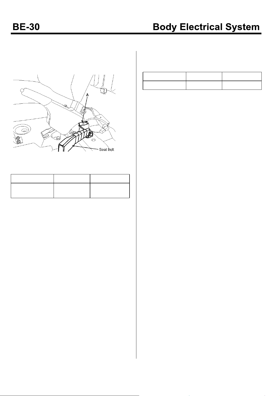
Seat Belt Warning Indicator
Inspection
Inspection of seat belt switch
1. Disconnect the seat belt switch connector (A).
EMTBE5019A
2. Check the continuity of the door switch.
Seat Belt Condition
Continuity
Fastened Not fastened
Non-Conductive
(∞)
Conductive (0 )
Inspection of Seat Belt Warning
Check that the following conditions are satisfied when
theignitionswitchisON.
Seat Belt Condition
Warning Lamp OFF ON
Fastened Not fastened
 Loading...