


Brake System
(WABCO ABS)
General
Description .................................................... |
BR -3 |
Components ................................................. |
BR -14 |
Dignosis ........................................................ |
BR -16 |
On-Vehicle Inspection And Adjustment ....... |
BR -20 |
Specifications ............................................... |
BR -22 |
Vacuum Assisted Hydraulic Brake
Brake Pedal |
|
Components............................................ |
BR -27 |
Removal .................................................. |
BR -28 |
Installation ............................................... |
BR -28 |
Adjustment .............................................. |
BR -28 |
Brake Booster |
|
Component ............................................. |
BR -30 |
Removal .................................................. |
BR -31 |
Installation ............................................... |
BR -32 |
Inspection ................................................ |
BR -33 |
Brake Master Cylinder |
|
Components............................................ |
BR -36 |
Removal .................................................. |
BR -37 |
Installation ............................................... |
BR -38 |
Load Sensing Proportioning Valve(LSPV) |
|
Components............................................ |
BR -39 |
Removal .................................................. |
BR -40 |
Inspection ................................................ |
BR -40 |
Front Brake Assembly
Disc Brake |
|
Components............................................ |
BR -41 |
Removal .................................................. |
BR -42 |
Installation ............................................... |
BR -43 |
Disassembly............................................ |
BR -44 |
Reassembly ............................................ |
BR -45 |
Inspection ................................................ |
BR -46 |
Drum Brake |
|
Components............................................ |
BR -48 |
Removal .................................................. |
BR -49 |
Replacement ........................................... |
BR -50 |
Installation ............................................... |
BR -51 |
Parking Brake System
Components ................................................. |
BR -52 |
Removal ....................................................... |
BR -53 |
Installation .................................................... |
BR -54 |
Adjustment .................................................... |
BR -56 |
Rear Brake Assembly
Drum Brake |
|
Components............................................ |
BR -57 |
Removal .................................................. |
BR -58 |
Replacement ........................................... |
BR -59 |
Installation ............................................... |
BR -61 |
Exhaust Brake |
|
Component Location .............................. |
BR -62 |
Components............................................ |
BR -63 |
Replacement ........................................... |
BR -67 |
Disassembly............................................ |
BR -68 |
Reassembly ............................................ |
BR -68 |
Inspection ................................................ |
BR -70 |
ABS(Anti-Lock Brake System)
Specifications ............................................... |
BR -72 |
|
Description .................................................... |
BR -72 |
|
Using Blink Code Diagnostics ..................... |
BR -76 |
|
DTC Troubleshooting ................................... |
BR -83 |
|
Repair Instruction ......................................... |
BR -88 |
|
Connector Configurations ............................ |
BR -90 |
|
Full Circuit Diagram ..................................... |
BR -91 |
|
Inspection ..................................................... |
BR -91 |
|
Adjustment .................................................... |
BR -92 |
|
ABS Modulator |
|
|
|
|
|
Removal .................................................. |
BR -94 |
|
Installation ............................................... |
BR -94 |
|
|
||
Wheel Speed Sensor |
|
|
Description .............................................. |
BR -95 |
|
Replacement ........................................... |
BR -95 |
|
ABS Control Module |
|
|
Removal .................................................. |
BR -97 |
|
Installation ............................................... |
BR -98 |
|
Schematic Diagrams .............................. |
BR -99 |
|
DTC Chart ............................................... |
BR -104 |
|
0000 ........................................................ |
BR -107 |
|
0001 ........................................................ |
BR -110 |
|
0002 ........................................................ |
BR -113 |
|
0003 ........................................................ |
BR -116 |
|
0004 ........................................................ |
BR -119 |
|
0009 ........................................................ |
BR -122 |
|
000A ........................................................ |
BR -125 |
|
000B ........................................................ |
BR -128 |
|
000C ........................................................ |
BR -131 |
|
000D ........................................................ |
BR -134 |
|
000E ........................................................ |
BR -137 |
|
000F ........................................................ |
BR -140 |
003D ........................................................ |
BR -233 |
0010 ........................................................ |
BR -143 |
003F ........................................................ |
BR -235 |
0011 ........................................................ |
BR -146 |
0040 ........................................................ |
BR -237 |
0017 ........................................................ |
BR -149 |
0041 ........................................................ |
BR -240 |
0018 ........................................................ |
BR -152 |
0042 ........................................................ |
BR -243 |
0019 ........................................................ |
BR -155 |
0043 ........................................................ |
BR -246 |
001A ........................................................ |
BR -158 |
0044 ........................................................ |
BR -249 |
001B ........................................................ |
BR -161 |
0045 ........................................................ |
BR -252 |
001C ........................................................ |
BR -164 |
0046 ........................................................ |
BR -255 |
001D ........................................................ |
BR -167 |
0047 ........................................................ |
BR -257 |
001E ........................................................ |
BR -170 |
0049 ........................................................ |
BR -260 |
001F ........................................................ |
BR -173 |
004A ........................................................ |
BR -263 |
0020 ........................................................ |
BR -176 |
004B ........................................................ |
BR -266 |
0021 ........................................................ |
BR -179 |
004C ........................................................ |
BR -269 |
0022 ........................................................ |
BR -182 |
004D ........................................................ |
BR -272 |
0023 ........................................................ |
BR -185 |
004E ........................................................ |
BR -275 |
0024 ........................................................ |
BR -188 |
004F ........................................................ |
BR -278 |
0029 ........................................................ |
BR -191 |
0050 ........................................................ |
BR -281 |
002A ........................................................ |
BR -194 |
0051 ........................................................ |
BR -284 |
002B ........................................................ |
BR -197 |
0052 ........................................................ |
BR -287 |
002C ........................................................ |
BR -200 |
0053 ........................................................ |
BR -290 |
002D ........................................................ |
BR -203 |
0054 ........................................................ |
BR -293 |
002E ........................................................ |
BR -206 |
0055 ........................................................ |
BR -296 |
002F ........................................................ |
BR -209 |
0056 ........................................................ |
BR -299 |
0030 ........................................................ |
BR -212 |
0057 ........................................................ |
BR -302 |
0032 ........................................................ |
BR -215 |
0058 ........................................................ |
BR -305 |
0033 ........................................................ |
BR -218 |
0059 ........................................................ |
BR -308 |
0037 ........................................................ |
BR -221 |
005A ........................................................ |
BR -311 |
0038 ........................................................ |
BR -223 |
005B ........................................................ |
BR -314 |
0039 ........................................................ |
BR -225 |
005C ........................................................ |
BR -317 |
003B ........................................................ |
BR -227 |
005D ........................................................ |
BR -320 |
003C ........................................................ |
BR -230 |
|
|

General
DESCRIPTION
BRAKE SYSTEM
The service brakes are internally expanding type hydraulic brakes acting on all wheels. The brakes for the front wheels are 2-leading type and those for the rear wheels are duo-servo or dual 2-leading type.
The brake booster gives faster hydraulic pressure buildup. Tandem type brake master cylinder also contributes to safety. The brake pedal, which is easy-to-operate pendant type, transmits depression force via operating rod, etc. to the BRAKE BOOSTER, which boosts it and drives the master cylinder.
The BRAKE BOOSTER vacuum line is equipped with a vacuum tank which minimizes negative pressure change even in the case of repeated and frequent braking operation.
Brake Booster
1.When not in Operation
When not in operation, no force acts on the operating rod and hence the valve plunger is seated on the poppet to open the negative pressure valve and to close the atmospheric valve.
Negative pressure generated by the engine draws out air from the chamber on the left side of the diaphragm plate. And as the chamber on the right side of the diaphragm plate is also evacuated via the vacuum channel and the negative pressure valve that is opened. As a result, the diaphragm plate is pressed tightly onto the rear shell surface by the diaphragm plate return spring. Atmosphere goes through the air filter into space around the operating rod but does not flow further as the atmospheric valve of the valve plunger is closed.
2.When in Operation
When the brake pedal depression force overcomes the valve return spring force, the operating rod, valve plunger and poppet now move to the left and the poppet is pressed tightly onto the valve plunger seat by the poppet spring, closing the negative pressure valve. When the brake pedal is further depressed following closure of this valve, the valve plunger clears the poppet to open the atmospheric valve and atmosphere now flows through the channel into the chamber on the right side of the diaphragm.
This flow of atmosphere produces the pressure difference across the diaphragm and the force resulting from such pressure difference overcomes the piston return spring force. As a result, the
diaphragm pushes the push rod as it moves from right to left. The push rod thus pushes the master cylinder piston, generating high fluid pressure from low pedal depression force.
SUDBR9016L
Brake Master Cylinder
1.Normal Operation
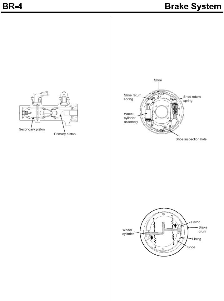
The tandem type brake master cylinder has independent hydraulic systems for front and rear brakes.
Should one of the two hydraulic systems fail, braking by survived system (front or rear wheels) ensures safety. When the brake pedal is depressed, the primary piston is pushed to left, developing hydraulic pressure in the pressure chamber on the primary side. This pressure directly acts on the secondary piston to push the secondary piston to left, developing hydraulic pressure also in the pressure chamber on the secondary side. As a result, each piston pressurizes brake fluid to generate hydraulic pressure in both front and rear brake systems.
SUDBR9017L
2.When fluid leaks are caused in front brake system
In this case, depression of the brake pedal to push the push rod does not develop hydraulic pressure as the brake fluid leaks from the front brake system. Therefore, the primary piston compresses the primary return spring and the retainer pushes the secondary piston, which then pressurizes brake fluid in space between the secondary piston and cylinder body, thus generating hydraulic pressure in the rear brake system only.
SUDBR9018L
3.When fluid leaks are caused in rear brake system
In this case, when the brake pedal is depressed to push out the push rod, the secondary piston end comes into contact with the cylinder body since brake fluid in the rear brake system leaks. When the push rod is further pushed, the primary piston pressurizes brake fluid in the space between the primary and secondary pistons, generating hydraulic pressure in the front brake system only.
Front And Rear Wheel Brakes Front wheel Brakes
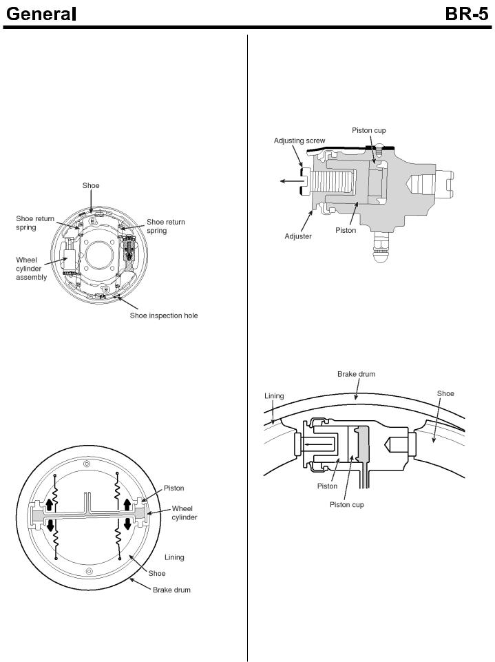
The wheel cylinder is so constructed that the piston extends in one direction only to push the shoes which are held down to the backing plate by the shoe hold down pin. The return springs mounted on the shoe fixed and moving sides cause contraction of the shoe and wheel cylinder piston when the brake is released.
When the vehicle is running forward, both shoes work as leading shoes.
EMTBR5004A
When the pedal is depressed, brake fluid supplied under pressure from the master cylinder enters the wheel cylinder, of which piston moves the shoe moving side so that the lining is pressed against the drum inside. Resultant friction between the lining and drum causes the shoe to try to turn with the drum, thus boosting the braking force.
EMTBR5005A
Rear Wheel Brake Dual 2-leading Brake
The wheel cylinders are installed at front and rear and the pistons extend in both upward and downward directions to push the shoes from both directions. The shoes are held down to the backing plate by shoe hold down pins and the return springs mounted on the shoes causing contraction of the shoe and wheel cylinder piston when the brake is released. During both forward and reverse operation of the vehicle, the shoes work as leading shoes.
EMTBR5004A
When the pedal is depressed, brake fluid supplied under pressure from the master cylinder enters the wheel cylinder, of which piston causes the shoe to expand in both directions to press the lining against the drum inside. Resultant friction between the lining and drum causes the shoe to try to turn with the drum, thus boosting the braking force.
EMTBR5006A
Wheel Cylinder
The wheel cylinder driven by hydraulic pressure generated by the brake master cylinder presses the shoe (lining) against the brake drum.
There are following two types of wheel cylinder according to the method of pushing the shoe.
EMTBR5007A
1.2-leading type : Front brake
In pedaling brake, oil pressure rising is master cylinder goes into wheel cylinder and pushes piston. Shoe contacting with the end of piston sticks to brake drum and generates frictional force.
EMTBR5008A
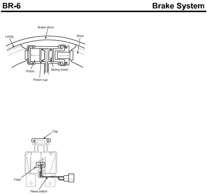
2. Dual 2-leading type : rear brake
EMTBR5009A
Brake Fluid Level Sensor
The brake fluid level sensor installed in the brake fluid tank senses the brake fluid level in the tank. When the fluid level drops to a preset level, the sensor operates to turn on the warning lamp in the cluster to warn low brake fluid level.
EMTBR5010A
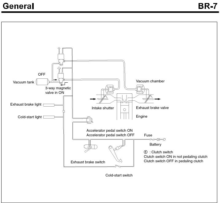
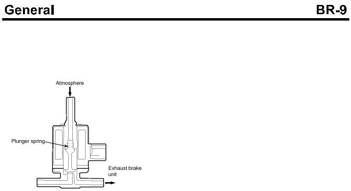
Exhaust Brake
SUDBRA015L
The exhaust brake system, as an assistant function of the service brake, comprises of the exhaust brake device installed at the middle portion of the exhaust pipe and the intake shutter installed at the intake manipulate to reduce the intake air noise.
When the exhaust brake device close the butterfly valve, the pressure inside of the pipe increases. This increased pressure influences to the piston to get the braking force. At that time, the intake shutter is also closed. When the clutch pedal, the accelerator pedal or the exhaust brake switch is released, the electric circuit is OFF and the exhaust brake is released.
The exhaust brake is the vacuum type assistant device which uses the negative pressure.

Intake Shutter
When the exhaust brake is operating, the intake shutter(A) reduces the amount of the intake air through the intake manipulate so as that the exhaust pressure is operated to the piston effectively. As a result, the noise will be reduced and the brake will be more effective.
KMTBR5513A
Exhaust Brake Unit
1.At Working
If the exhaust brake switch is ON, the three-way magnetic valve is opened. The vacuum pressure of the vacuum tank is applied to the exhaust brake unit so as to pull the piston.
As a result, the butterfly valve linked to the push rod is closed so that the exhaust brake is working.
EMTBR5012A
2.At releasing
If the exhaust brake switch, the clutch switch and the accelerator switch are OFF, the 3-way magnetic valve closes the circuit to the vacuum tank and opens the atmosphere circuit.
Therefore, the atmospheric pressure is applied to the exhaust brake unit. Due to the spring tension, the butterfly valve is opened. The exhaust brake is released.
EMTBR5013A
The 3-way Magnetic Valve
1.At working
If the exhaust brake switch is ON, an electric current will flow through the coil and then a magnetic field is formed. The magnetic force pulls the plunge to upward. At that time, the valve seat at the plunger closes the way to the atmosphere pressure while it opens the way linking the vacuum tank and the brake chamber.
EMTBR5014A
2.At releasing
If the exhaust brake switch is OFF, the electric current flowing through the coil is shut down. Due to the spring tension, the plunger will be pushed so as to close the way to vacuum tank while the way to the atmosphere pressure and the brake chamber.
EMTBR5060A
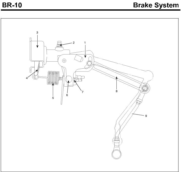
LOAD SENSING PROPORTIONING VALVE
SUDBRA021L
1. |
LSPV assembly |
4. |
Lever assembly |
7. |
Adjusting nut |
2. |
Bleeder screw |
5. |
Sensor spring |
8. |
Operating lever |
3. |
Bracket |
6. |
Spring guide |
9. |
Connecting link assembly |
Construction
LSPV is consist of sensor part and pressure controller part.
1.Sensor part
It consists of spring, operating lever, link. It senses the height of vehicle with varying according to the amount loads
2.Pressure controller part
It consists of valve stem mechanism for proportioning control of sensor force.
EMTBR5016A
Operating Principle
LSPV body is mounted in the frame and the end of the link is mounted in the rear axle. With varying of amount of vehicle load changes the relative position of frame and rear axle, so sensor spring force varies to the valve stem. It controls the rear axle brake fluid pressure.
1.Unloaded status
The sensor spring presses the valve stem slightly, so the brake fluid pressure is set weakly.
2.Loaded status
The sensor spring presses the valve stem strongly, so the brake fluid pressure is set highly.
 NOTICE
Don't loose or don't retighten the adjusting nut crimping.
SUDBR9036L
Service and Inspection of the LSPV
Check the LSPV as below when replace the sensor spring, valve body assembly or reinstall the rear axle, rear spring.
Symptom |
Probable Cause |
Remedy |
|
|
|
Braking force is i- |
Insufficient air bl- |
Air bleeding |
nsufficient. |
eeding |
|
|
|
|
|
Maladjusted sen- |
Readjust |
|
sor spring |
|
|
|
|
|
Sensor spring br- |
Replace valve a- |
|
oken |
ssembly |
|
|
|
|
Oil leakage in the |
Tighten brake flu- |
|
brake fluid line or |
id line or replace |
|
LSPV assembly |
LSPV assembly |
|
|
|
Rear brake is loc- |
Maladjusted sen- |
Readjust |
k too fast. |
sor spring |
|
|
|
|
|
Inner fault the L- |
Replace LSPV a- |
|
SPV |
ssembly |
|
|
|

PARKING BRAKE GENERAL
SUDBRA022L
1.Parking brake lever assembly
2.Cam lever
3.Parking brake drum
4.Adjusting nut
5.Parking brake cable
The parking brake installed behind the transmission is an internal expansion type acting on the propeller shaft.
It controls propeller shaft rotation to work as a parking brake.
The control is wire mechanical type; brake shoes are pressed via a wire to control the propeller shaft.
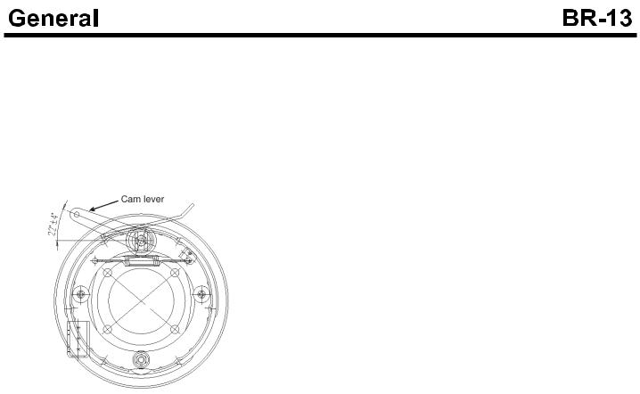
Parking Brake Proper
When the lever at the driver's seat is pulled, the cam lever is actuated via a wire cable and resultant cam rotation causes the brake shoes to expand and be forced against the brake drum. The braking force is thus obtained by friction between the shoes and drum. When the lever is released, the cam lever returns to the initial position and the braking force is released by the brake shoe return springs.
EMTBR5019A

COMPONENTS(LHD)
SUDBRA001L
1.Vacuum tank
2.Vacuum hose
3.Brake booster
4.Master cylinder
5.Reservoir tank
6.A.B.S modulator
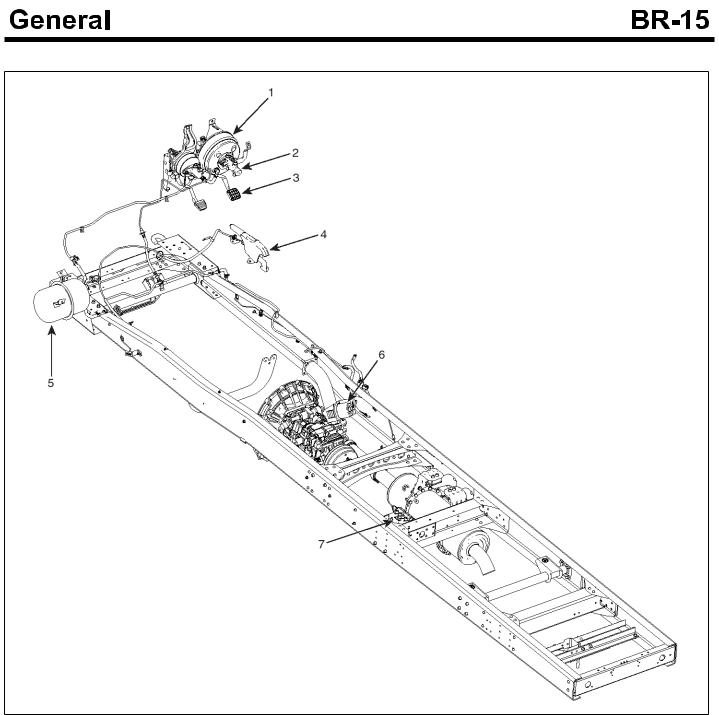
COMPONENTS(RHD)
SUDBRA002L
1.Brake booster
2.Master cylinder
3.Brake pedal
4.Parking brake lever
5.Vacuum tank
6.Exhaust brake
7.ABS HECU(Hydraulic Electrical Control Unit)

Diagnosis
Symptom |
Causes |
Remedy |
Remark |
||
Irregular Braking |
The air pressures of tire are different. |
Adjust the air pressure of tire. |
|
|
|
Force |
|
|
|
|
|
|
The sizes of the right and left tires are different |
Replace the tire. |
|
|
|
|
|
|
|
||
|
|
. |
|
|
|
|
|
The adjustment of the wheel bearing is defecti- |
Adjust (Check the wheel bearing) |
|
|
|
|
ve. |
|
|
|
|
|
The sizes of the right and left wheel bases are |
Check and adjust the loosening the U-b- |
|
|
|
|
different. |
olt or damages on center bolt. |
|
|
|
|
|
|
|
|
|
|
The wheel alignment is defective. |
Adjust |
|
|
|
|
|
|
|
|
After releasing t- |
The vertical surface of the back plate is rough. |
Replace the back plate or check the lini- |
|
|
|
he brake |
pedal, |
ng. |
|
|
|
the braking force |
|
|
|
|
|
The operation of the wheel cylinder is defective |
Check the contacting, the piston cup and |
|
|
||
is release too la- |
. |
wearing status. If needed, replace it. Ch- |
|
|
|
te. |
|
|
eck the lining. |
|
|
|
|
|
|
|
|
|
|
|
|
|
|
|
|
The return spring is damaged. |
Replace the spring. |
|
|
|
|
|
|
|
|
Unbalance at th- |
The surface of the lining is contaminated by th- |
If it is contaminated by oil or grease, the- |
|
|
|
e right and left |
n replace it. If it is contaminated by water |
|
|
||
braking force |
e oil, grease or water. |
, dry it. |
|
|
|
|
|
|
|||
|
|
|
|
|
|
|
|
The lining is defective or The material of lining |
Replace or adjust. |
|
|
|
|
is improper. |
|
|
|
|
|
The wear is irregular. The surface is rough. |
Replace the lining. Check the inside of t- |
|
|
|
|
|
he drum, if needed, replace it. |
|
|
|
|
|
|
|
|
|
|
The lining contact is defective. |
Adjust the lining with being installed. |
|
|
|
|
|
|
|
|
|
|
The brake drum is worn irregularly. |
Adjust or replace it. |
|
|
|
|
|
|
|
|
Unstable brakin- |
The brake drum is deformed. |
Replace |
|
|
|
g force |
|
|
|
|
|
|
The back plate is deformed or loosened. The |
If it is loosened, tighten with specified to- |
|
|
|
|
|
|
|
||
|
|
vertical surface of it is rough. |
rque. Otherwise, replace it. |
|
|
|
|
|
|
|
|
Improper |
Lock |
The drum is worn. |
Adjust or Replace |
Drum |
limit |
Point |
|
|
|
STD |
|
|
|
|
|
+ |
|
|
|
|
|
: Dia |
2m- |
|
|
|
|
m |
|
|
|
|
|
|
|
|
|
The lining is worn irregularly. |
Adjust |
|
|
|
|
|
|
|
|
|
|
The lining contact is defective. |
Adjust with being installed. |
|
|
|
|
|
(Temperature of lining should be less th- |
|
|
|
|
|
° |
|
|
|
|
|
an 100 C) |
|
|

Symptom |
Causes |
Remedy |
Remark |
|
|
|
|
|
|
Low Braking Fo- |
The clearance between the brake pedal and fl- |
Refer to the item for decreasing the clea- |
|
|
rce |
oor is 45mm or more. (at Pressure-600mmHg, |
|
||
|
Pressure 50kg) |
|
rance between the brake pedal and floor. |
|
|
|
|
|
|
|
|
|
|
|
|
The lining contact is defective. |
Adjust with being installed not being dis- |
|
|
|
|
|
assembled. (Temperature should be 100 |
|
|
|
|
° |
|
|
|
|
C or less) |
|
|
The surface of the lining is contaminated by th- |
If it is contaminated by oil or grease, the- |
|
|
|
e oil, grease or water. |
|
n replace it. If it is contaminated by water |
|
|
The lining is deteriorated. |
, dry it. |
|
|
|
|
|
|
|
|
The vacuum force is too low. |
Replace the lining. |
|
|
|
|
|
|
|
|
The drum surface is rough. |
Check the pipe or the vacuum pump. If |
|
|
|
|
|
needed, replace. |
|
|
|
|
|
|
|
The brake booster is defective. |
Adjust or Replace |
|
|
|
|
|
|
|
|
The brake oil level is too low. |
Adjust or Replace |
|
|
|
|
|
|
|
The clearance b- |
The air intrudes. |
|
Refill |
|
etween the ped- |
|
|
|
|
Vapor lock |
|
Air Exhausting |
|
|
al and the floor i- |
|
|
|
|
The adjustment on pedal is defective. |
Referring to the brake drawn item, adjust |
|
||
s too narrow. |
|
|||
|
The clearance is too large. |
or replace. And then exhaust the air. |
|
|
|
The shoe clearance is too large. |
Adjust the pedal clearance. Check the t- |
|
|
|
otal stroke. |
|
||
|
|
|
|
|
|
|
|
|
|
|
The cup of the master cylinder is defective. |
Adjust the shoe clearance. |
|
|
|
|
|
If the wear exceeds the limit, replace. |
|
|
|
|
|
|
|
The brake shoe is deformed or damaged. |
If the tightening does not satisfy the spe- |
|
|
|
|
|
cifications, replace the kit. |
|
|
|
|
|
|
|
The brake booster is defective. |
Replace |
|
|
|
|
|
|
|
|
When the wheel is rotating with being lifted by |
Replace |
|
|
|
jack, there are some noises. |
|
|
|
During braking, |
During braking (at low |
Foreign materials in d- |
Check that the brake is damaged. Remo- |
|
the noise and s- |
speed), noise is made |
rum |
ve the foreign materials. |
|
hock are made |
continually. |
|
|
|
Return spring is dama- |
Check that the parts are damaged by br- |
|
||
abnormally. |
|
|
||
|
ged. |
oken parts. If needed, replace. |
|
|
|
|
|
||
|
|
|
|
|
|
|
Hold down cup is dam- |
Check that the parts are damaged by br- |
|
|
|
aged. |
oken parts. If needed, replace. |
|
|
|
|
|
|
|
The grease is deficien- |
Improper adjustment |
Check the rotating surface. Adjust |
|
|
cy in sliding parts. |
on wheel bearing |
|
|
|
|
The lining is worn. |
Replace |
|
|
|
|
|
|
|
The drum inside surface is rough. |
Apply the grease. |
|
|
|
|
|
|
|
|
|
|
Modify the inner surface with sand paper |
|
|
The drum is cracked. |
|
. |
|
|
|
|
Replace |
|
|
|
|
|
|

Symptom |
Causes |
Remedy |
|
Remark |
||
|
|
|
|
|
||
The drum is ove- |
The outlet of the brake master cylinder is clog- |
If the booster operating rod is not proper- |
|
|||
rheated. |
ged. |
|
ly adjusted, adjust the pedal clearance of |
|
||
|
|
|
|
~ |
|
|
|
|
|
|
the rod clevis to 10 15mm. |
|
|
|
The brake does not return. |
Check the burst of the return spring, the |
|
|||
|
|
|
|
bearing lubricant, the stop lamp switch a- |
|
|
|
|
|
|
djustment. If needed, adjust. |
|
|
|
|
|
|
|
|
|
|
The booster is defective. |
Replace |
|
|
||
|
|
|
|
|
|
|
|
The vertical surface of the back plate is scratc- |
If the surface is too rough, replace. |
|
|
||
|
hed. |
|
If it is too dry, apply the grease. |
|
|
|
|
|
|
|
|
|
|
|
The wheel cylinder piston cup is defective. |
Replace |
|
|
||
|
|
|
|
|
||
|
The oil return has problems due to the over tig- |
Check the connector hole diameter. If it |
|
|||
|
ht of the brake pipe nut. |
|
is reduced, replace. |
|
|
|
|
|
|
|
|
|
|
|
When the wheel is rot- |
The wheel bearing cle- |
Replace bearing or adjust. |
|
Specific |
|
|
ating with being lifted |
|
arance is too large. |
|
|
wheel is o- |
|
by jack, the wheel is h- |
|
|
|
|
verheated. |
|
|
Shoe clearance is imp- |
Adjust |
|
||
|
ard to rotate. |
|
roper. |
|
|
|
|
|
|
|
|
|
|
|
|
|
|
|
|
|
|
|
|
Return spring is defec- |
Check the part damages due to the spri- |
|
|
|
|
|
tive. |
ng over working. If needed replace. |
|
|
|
|
|
|
|
|
|
|
|
|
Brake shoe is worn. |
Replace |
|
|
|
|
|
|
|
|
|
The pedal retur- |
The pedal linkage is rusted or deformed. |
Disassemble. Adjust or replace. Oil the |
|
|||
ning is defective. |
grease. |
|
|
|||
|
|
|
|
|
||
|
It is bursting due to the defectives on the pedal |
Replace |
|
|
||
|
return spring. |
|
|
|
|
|
|
|
|
|
Adjust the pedal clearance with 10 |
~ |
|
|
The booster operating rod is pushed. |
15 |
|
|||
|
mm. |
|
|
|||
|
|
|
|
|
|
|
|
|
|
|
|
||
Brake is vibratin- |
The drum is eccentrically centered. |
Replace |
|
|
||
g. |
|
|
|
|
|
|
The drum is deformed. |
|
Replace |
|
|
||
|
|
|
|
|||
|
|
|
|
|
||
|
The king pin bushing is worn. |
Replace the bushing |
|
|
||
|
|
|
|
|
|
|
|
The hub bearing is worn. |
Adjust (Check the rolling surface) or repl- |
|
|||
|
ace. |
|
|
|||
|
|
|
|
|
|
|
|
|
|
|
|
||
Brake is drawn. |
The pedal clearance is too narrow. |
Adjust the booster working rod. |
|
|
||
|
|
|
|
|
||
|
The shoe clearance is improper. |
Adjust |
|
|
||
|
|
|
|
|
||
|
The back plate vertical surface is rough. |
Replace the back plate. |
|
|
||
|
|
|
|
|
||
|
The shoe spring is burst. |
Replace |
|
|
||
|
|
|
|
|
||
|
The master cylinder or wheel cylinder piston c- |
Replace |
|
|
||
|
up is deteriorated and swelled. |
|
|
|
||

Symptom |
Causes |
Remedy |
Remark |
|
|
|
|
Brake makes n- |
Brake shoe contacting is defective. |
Adjust the lining with being installed not |
|
oises. |
|
being disassembled (Temperature shoul- |
|
|
|
° |
|
|
|
d be 100 C or less) |
|
|
Lining is deformed. |
Replace the lining. Replace the drum if it |
|
|
|
has hardened surface. |
|
|
|
|
|
|
Drum has hardened surface. |
Replace. |
|
|
|
|
|
|
Shoe is deformed. |
Replace. |
|
|
|
|
|
|
Back plate is deformed or installed improperly. |
Replace or adjust |
|
|
|
|
|
|
Front bearing is loosened. |
Adjust (Check the rolling surface) |
|
|
|
|
|
|
Powder from the wear of the lining is adhered. |
Clear |
|
|
|
|
|
|
Lining is worn. |
Replace. |
|
|
|
|
|
Exhaust brake |
Vacuum pressure is improper. |
Check the vacuum pump or piping. If ne- |
|
does not work. |
|
eded repair. |
|
|
Electric circuit is defective. |
Check the clutch switch, the micro switch |
|
|
|
and the exhaust brake circuit. If needed, |
|
|
|
repair. |
|
|
|
|
|
|
Vacuum pipe is damaged. |
Replace. |
|
|
|
|
|
|
3-way magnetic valve does not work. |
Replace. |
|
|
|
|
|
|
Exhaust brake valve does not work. |
Replace. |
|
|
|
|
|
|
Exhaust brake valve shaft is adhered. |
Replace. |
|
|
|
|
|
|
Power chamber is defective. |
Disassemble and check. |
|
|
|
|
|
Exhaust brake c- |
3-way magnetic valve does not work. |
Replace. |
|
an not be relea- |
|
|
|
Exhaust brake valve does not work. |
Replace. |
|
|
sed. |
|
|
|
Exhaust brake valve shaft is adhered. |
Replace. |
|
|
|
|
||
|
|
|
|
|
Electric circuit is defective. |
Check the clutch switch, the micro switch |
|
|
|
and the exhaust brake circuit. If needed, |
|
|
|
repair. |
|
|
|
|
|
Diagnosis (Parking brake)
Symptom |
|
Causes |
Remedy |
Remark |
Parking brake d- |
Operating |
When pulling the parking brake wi- |
Adjust the shoe clearance and cable. |
|
oes not work. |
mechanis- |
th 30kg, there is no lever stroke cl- |
|
|
|
m has a p- |
earance and shoe clearance. |
|
|
|
roblem. |
|
|
|
|
The locking status between the le- |
Adjust the Ratchet pull lock status. Repl- |
|
|
|
|
|
||
|
|
ver lock latch and Ratchet pull is i- |
ace it |
|
|
|
mproper. |
|
|
|
|
|
|
|
|
|
Wire is broken or elongated. |
Replace the cable. |
|
|
|
|
|
|
|
Parking b- |
Tolerance between the shoe clear- |
Adjust the shoe clearance. |
|
|
rake is de- |
ance and the brake lever pulling is |
|
|
|
fective. |
too large. |
|
|
|
|
|
|
|
|
|
Drum inner surface is deformed or |
Repair the drum inner surface. Replace |
|
|
|
twisted. |
the lining. |
|
|
|
|
|
|
|
|
Lining is irregularly worn. Drum in- |
Replace the lining. |
|
|
|
ner surface is contacted irregularly |
|
|
|
|
. |
|
|
|
|
|
|
|
|
|
The oil of drum and lining is conta- |
Clear the inner surface of the drum. Rep- |
|
|
|
minated. |
lace the lining. |
|
|
|
|
|
|
Parking brake c- |
Operating |
Return spring is damaged. The te- |
Replace the return spring. |
|
an not be relea- |
mechanis- |
nsion of the return spring is inferior |
|
|
sed. |
m has a p- |
. |
|
|
|
roblem. |
|
|
|
|
The inner cable does not move s- |
Replace the cable. |
|
|
|
|
|
||
|
|
moothly. |
|
|
|
|
|
|
|
|
|
After the parking brake is released |
Adjust the pulling tolerance limit. |
|
|
|
, the brake is operating. |
|
|
|
|
|
|
|
|
Parking b- |
Return spring is damaged. The te- |
Replace the return spring. |
|
|
rake is de- |
nsion of the return spring is inferior |
|
|
|
fective. |
. |
|
|
|
|
|
|
|
|
|
The shoe clearance is too narrow. |
Adjust the shoe clearance. |
|
|
|
|
|
|
|
|
|
|
|
On-Vehicle Inspection and Adjustment
Air bleeding of the Brake
1.Fill up the brake oil tank with the brake oil at the maximum level. During the air bleeding, if the level is lowered, refill the brake oil.
 CAUTION
Be careful that the brake oil does not drop on the painted surface. If the brake oil contacts the painted surface, immediately wash it by water.
2.Connecting an end of transparent vinyl tubes at the air breather of the front wheel cylinder and the rear wheel cylinder, put the other end of the tubes into the transparent container having the brake oil.
KMTBR5518A
3.Step on the brake pedal several times. Pressing the brake pedal at half, loosen the air bleeder screw to evacuate the air with the brake oil.
And then, pressing the pedal until it reaches to the floor, tighten the air bleeder screw. Release the pedal. There procedures should be repeated until any air bubble is not shown in the brake oil.
KMTBR5519A
4. Tighten the bleeder screw
Tightening Torque for the bleeder Screw Front: 6.9~8.8Nm(0.7~0.9kgf.m, 5.1~6.5lb-ft) Rear : 6.9~8.8Nm(0.7~0.9kgf.m, 5.1~6.5lb-ft)
5.Step on the brake pedal several times. Pressing the brake pedal at half, loosen the air breather screw to evacuate the air with the brake oil.
And then, pressing the pedal until it reaches to the floor, tighten the air breather screw. Release the pedal. There procedures should be repeated until any air bubble is not shown in the brake oil.
KMTBR5520A
Adjustment of Brake Shoe Gap
1.Using the screw driver(A), turn the wheel cylinder adjuster(B) to the shoe expansion direction until the drum is not rotate anymore. Turn the adjuster reversely with the following notch number. (At that time, the drag torque between the lining and the drum should be less than 50kgf.m).
|
KMTBR5521A |
||
The Notch Number for reverse rotation of the |
|||
Adjuster. |
|
|
|
|
|
|
|
Front Wheel Cylinder |
Auto adjuster type |
~ |
|
9 |
11 |
||
|
Manual adjuster type |
~ |
|
|
4 |
6 |
|
Rear Wheel Cylinder |
Auto adjuster type |
~ |
|
9 |
11 |
||
|
Manual adjuster type |
~ |
|
|
4 |
6 |
|

Specifications
Front Wheel Brake (Drum Type)
Item |
|
Specifications |
|
|
|
Brake type |
|
2-leading Brake |
|
|
|
Wheel cylinder |
Inner diameter |
31.75mm |
|
|
|
Brake drum |
Inner diameter |
320mm |
|
|
|
Brake lining |
Width x Thickness (mm) |
85 x 10(Standard), 110 x 11(Option in case of HD72,78) |
|
|
|
Front wheel Brake (Disk Type)
Item |
Specifications |
|
|
Cylinder diameter |
Ø 76 mm |
|
|
Effective radius |
118 mm |
|
|
Disk outer diameter |
Ø 304 mm |
|
|
Disk inner diameter |
Ø 164 mm |
|
|
Pad thickness |
12.5 mm |
|
|
Pad effective thickness |
10.5 mm |
|
|
Rear Wheel Brake
Item |
|
Specifications |
|
|
|
Brake type |
|
2-leading Brake |
|
|
|
Wheel cylinder |
Inner diameter |
28.57mm |
|
|
|
Brake drum |
Inner diameter |
320mm |
|
|
|
Brake lining |
Width x Thickness (mm) |
85 x 10(Standard), 110 x 11(Option in case of HD72,78) |
|
|
|
Brake system
Item |
|
|
Specification |
|
|
|
|
Brake Pedal |
Total Stroke |
|
140 mm |
|
|
|
|
Booster |
Total Stroke |
|
31 mm |
|
|
|
|
Master Cylinder |
Inner Diameter |
|
Ø 31.75 mm, Ø 30.15 mm |
|
|
|
|
|
Stroke |
Piston |
± |
|
31 1 mm |
||
|
|
Primary |
17 ± 0.5 mm |
|
|
|
|
|
|
Secondary |
14 ± 0.5 mm |
|
|
|
|

Exhaust Brake
Item |
|
|
Specification |
|
Control System |
|
|
Combination of Electric and Vacuum Type |
|
|
|
|
|
|
Exhaust Brake Valve Type |
|
Butterfly Valve |
||
|
|
|
|
|
Exhaust Brake Cham- |
Diaphragm Effective Diameter |
76.2mm |
|
|
ber |
|
|
|
|
With Installing |
Spring Tension |
~ |
~ |
|
|
90 110 (9.18 |
11.22) |
||
|
N(kg) |
|
|
|
|
Rod Tensile Force |
142.1(14.5): Vacuum Pressure-400mmHg |
||
|
|
|||
|
|
|
|
|
|
|
Spring Tension |
~ |
~ |
|
|
125 153 (12.78 15.62) |
||
|
|
Rod Tensile Force |
103(10.5) Vacuum Pressure-400mmHg |
|
|
|
|
|
|
Parking brake
Item |
|
Specification |
|
|
|
|
|
Type |
|
Internal expansion type acting on propeller shaft |
|
|
|
|
|
Control |
|
Mechanical cable |
|
|
|
|
|
Parking lever |
Normal stroke |
~ |
|
8 9 clicks(20 kgf) |
|||
Parking brake size |
Drum i.d. x Lining width x Li- |
180 x 35 x 5 |
(T/M : M2S5, M3S5) |
|
ning thickness |
190 x 45 x 4 |
(T/M : M035S5) |
|
|
230 x 55 x 4 |
(T/M : T60S5, T60S6) |
|
|
|
|

SERVICE STANDARDS
|
|
|
Description |
|
Nominal value, mm |
Limit |
Correction and |
|
|
|
|
|
(Basic diameter in [ ]) |
(mm) |
remarks |
||
|
|
|
|
|
||||
|
|
|
|
|
|
|
|
|
Brake |
Bushing to collar clearance |
|
[16]0.02 to 0.26 |
0.5 |
Replace bushing |
|||
pedal |
|
|
|
|
|
|
|
|
Brake pedal play |
|
|
3-8 |
|
|
Adjust |
||
|
|
|
|
|
||||
|
|
|
|
|
|
|
|
|
|
Stop lamp switch installation clearance |
0 to 1 |
|
|
Replace |
|||
|
|
|
|
|
|
|
|
|
Brake |
Primary and secondary piston to cylinder body clearance |
0.038 ~ 0.145 |
0.2 |
Replace |
||||
master |
|
|
|
|
|
|
|
|
cylinder |
|
|
|
|
|
|
|
|
Primary retainer assembly |
Free length |
38.1 |
|
|
Replace |
|||
|
|
|
|
|
|
|
|
|
|
Secondary spring deterioratio- |
Free length |
37.7 |
|
|
Replace |
||
|
n |
|
|
|
|
|
|
|
|
|
|
|
|
|
|
|
|
Front |
Brake drum |
|
I.D. |
|
320 |
|
322 |
Replace |
drum b- |
|
|
|
|
|
|
|
|
Brake lining |
|
Thickness |
|
10 |
|
4 |
Replace |
|
rake |
|
|
|
|
|
|
|
|
Return spring |
|
|
± |
|
19/227 |
Replace |
||
|
|
|
|
|||||
|
|
|
30 3/227 |
|
||||
|
Wheel cylinder body to piston clearance |
[31.75]0.03 to 0.13 |
0.2 |
Replace |
||||
|
|
|
|
|
|
|
|
|
|
Brake shoe clearance(No. of notches returned of wheel c- |
Auto |
~ |
|
Adjust |
|||
|
9 11 |
|
||||||
|
ylinder adjuster) |
|
|
|
|
|
|
|
|
|
|
Manual |
~ |
|
|
||
|
|
|
|
|
4 6 |
|
|
|
Rear w- |
Brake drum |
|
I.D. |
|
320 |
|
322 |
Replace |
heel br- |
|
|
|
|
|
|
|
|
Brake lining |
|
Thickness |
|
10 |
|
4 |
Replace |
|
ake |
|
|
|
|
|
|
|
|
Return spring |
|
Load N(kgf)/installed length |
± |
|
19/227 |
Replace |
||
|
|
|
||||||
|
|
30 3/227 |
|
|||||
|
Wheel cylinder |
|
Body to piston clearance |
0.02-0.11 |
|
0.2 |
Replace |
|
|
|
|
|
|
|
|
|
|
|
Brake drum |
|
Out of roundness |
0.05 |
|
- |
Replace |
|
|
|
|
|
|
|
|
|
|
|
Brake shoe clearance (number of return notches of wheel |
Auto |
~ |
|
Adjust |
|||
|
9 11 |
|
||||||
|
cylinder adjuster) |
|
|
|
|
|
||
|
|
Manual |
~ |
|
|
|||
|
|
|
|
|
4 6 |
|
|
|

|
|
Description |
|
|
Nominal value, mm |
Limit |
Correction and |
|
|
|
|
(Basic diameter in [ ]) |
(mm) |
remarks |
|
|
|
|
|
|
|||
|
|
|
|
|
|
|
|
Exhau- |
Power chamber air tightness [15 seconds after applicatio- |
-63 kPa (-475 mmHg) or |
|
Replace |
|||
st brak- |
n of -67 kPa (-500 mmHg) negative pressure] |
|
more |
|
|
||
e |
|
|
|
|
|
|
|
Valve to body clearance when butterfly valve is fully clos- |
0.1 to 0.4mm |
|
Replace |
||||
|
|
||||||
|
ed [at power chamber vacuum -87 to -93 kPa(-650 to -70 |
|
|
|
|||
|
0 mmHg) |
|
|
|
|
|
|
|
|
|
|
|
|
|
|
|
3-way magnet |
Air tightness |
When -100 kPa (-750 m- |
No air to be sucked in f- |
|
Replace |
|
|
valve |
|
mHg) negative pressure is |
rom atmosphere side |
|
|
|
|
|
|
applied from vacuum tan- |
|
|
|
|
|
|
|
k side to operate valve wi- |
|
|
|
|
|
|
|
th exhaust brake unit side |
|
|
|
|
|
|
|
plugged tightly |
|
|
|
|
|
|
|
|
|
|
|
|
|
|
|
When 98 kPa (1 kgf/cm² |
No air to leak from vacu- |
|
Replace |
|
|
|
|
air pressure is applied fro- |
um tank side |
|
|
|
|
|
|
m atmosphere side to op- |
|
|
|
|
|
|
|
erate valve with exhaust |
|
|
|
|
|
|
|
brake unit side plugged ti- |
|
|
|
|
|
|
|
ghtly |
|
|
|
|
|
|
|
|
|
|
|
|
|
|
Minimum op- |
When -100 kPa(-75 |
24V |
22V or less |
|
Replace |
|
|
erating volta- |
0 mmHg) negative |
type |
|
|
|
|
|
ge |
pressure is applied |
unit |
|
|
|
|
|
|
to vacuum tank side |
|
|
|
|
|
|
|
|
|
|
|
|
|
|
|
When 98 kPa (1 kgf |
24V |
22V or less |
|
Replace |
|
|
|
/cm² air pressure is |
type |
|
|
|
|
|
|
applied from atmos- |
unit |
|
|
|
|
|
|
phere side with exh- |
|
|
|
|
|
|
|
aust brake unit side |
|
|
|
|
|
|
|
plugged tightly |
|
|
|
|
|
|
|
|
|
|
|
|

SERVICE STANDARDS (Parking brake)
Description |
|
|
Nominal value, mm |
Limit |
Correction |
and |
|
|
|
|
(Basic diameter in [ ]) |
(mm) |
remarks |
|
|
|
|
|
|
|
|
|
|
Brake drum |
I.D. |
|
180 |
181 |
Correct |
to |
limit, |
|
|
|
|
|
replace |
when li- |
|
|
|
|
190 |
192 |
|||
|
|
|
mit is reached. |
||||
|
|
|
|
|
|||
|
|
|
230 |
232 |
|||
|
|
|
|
|
|
||
|
|
|
|
|
|
||
|
Squareness |
|
0.05 or less |
|
Correct or repla- |
||
|
|
|
|
|
ce |
|
|
|
Concentricity |
|
0.1 or less |
|
|
|
|
|
|
|
|
|
|
||
|
|
|
|
|
|
|
|
|
Cylindricity |
|
0.1 or less |
|
|
|
|
|
|
|
|
|
|
|
|
|
Static rotation imbalance |
0.49 N.cm(50 gf.cm) or l- |
|
|
|
|
|
|
|
|
ess |
|
|
|
|
|
|
|
|
|
|
|
|
Brake lining thickness |
Model with M2S5 T/M |
10 ~ 11 |
4.0 |
Replace |
|
|
|
|
|
|
|
|
|
|
|
Brake shoe clearance |
Model with M2S5 T/M |
0.25 to 0.35 |
|
Adjust |
|
|
|
|
|
|
|
|
|
|
|
Brake shoe r- |
Free length |
Model with M2S5 T/M |
98 |
- |
|
|
|
eturn spring |
|
|
|
|
|
|
|
Load N (kgf)/instal- |
Model with M2S5 T/M |
67 to 86 (6.8 to 8.8)/104 |
104.364 |
Replace |
|
|
|
|
|
|
|||||
|
led length |
|
|
(6.5)/104 |
|
|
|
|
|
|
|
|
|
|
|
Shoe hold d- |
Spring A(longer o- |
Free length |
34.1 |
|
Replace |
|
|
own spring |
ne of free length) |
|
|
|
|
|
|
Load N (kgf)/installed l- |
59 to 69 (6.0 to 7.0)/13.7 |
59 (6.0)/13.7 |
|
|
|
||
|
|
|
|
|
|||
|
|
ength |
|
|
|
|
|
|
|
|
|
|
|
|
|
|
Spring B(shorter o- |
Free length |
23.6 |
|
|
|
|
|
ne of free length) |
|
|
|
|
|
|
|
Load N (kgf)/installed l- |
59 to 69 (6.0 to 7.0)/10.5 |
59 (6.0)/10.5 |
|
|
|
|
|
|
|
|
|
|||
|
|
ength |
|
|
|
|
|
|
|
|
|
|
|
|
|
Tightening torque table
Description |
Tightening torque |
|
|
|
|
||
|
|
|
|
|
|||
|
Nm |
|
Kgf.m |
Lb-ft |
|||
|
|
|
|
|
|
||
Mounting nut between the master cylinder and booster |
|
~ |
|
~ |
~ |
||
17.7 24.5 |
|
1.8 |
2.5 |
13 |
18.1 |
||
Master cylinder set bolt |
~ |
|
~ |
8.7 |
~ |
||
12 |
16 |
|
1.2 |
1.6 |
11.6 |
||
Brake booster mounting nut |
|
~ |
|
~ |
9.4 |
~ |
|
12.7 15.7 |
|
1.3 |
1.6 |
11.8 |
|||
Brake booster clevis lock nut |
|
~ |
|
~ |
|
~ |
|
15.7 21.6 |
|
1.6 |
2.2 |
11.6 15.9 |
|||
Master cylinder outlet port nut |
|
~ |
|
~ |
9.4 |
~ |
|
12.7 16.8 |
|
1.3 |
1.7 |
12.3 |
|||
LSPV connecting link mounting bolt |
~ |
|
~ |
|
~ |
||
22 |
33 |
|
2.2 |
3.3 |
15.9 23.9 |
||
LSPV flange bolt mounting bolt |
~ |
|
~ |
|
~ |
||
22 |
33 |
|
2.2 |
3.3 |
15.9 23.9 |
||
Front drum brake air bleeding port |
6.9 |
~ |
|
~ |
5.1 |
~ |
|
12.7 |
|
0.7 |
1.3 |
9.4 |
|||
Front spindle mounting bolt |
~ |
|
~ |
~ |
|||
98 |
137 |
|
10 |
14 |
72 |
101 |
|
Brake hose to union mounting bolt(Front drum brake) |
|
~ |
|
~ |
|
~ |
|
24.5 29.4 |
|
2.5 |
3 |
18.1 21.7 |
|||
Exhaust brake to exhaust pipe mounting bolt |
|
~ |
|
~ |
|
~ |
|
44.1 58.8 |
|
4.5 |
6 |
32.5 43.4 |
|||
Vacuum Assisted Hydraulic Brake
Brake Pedal
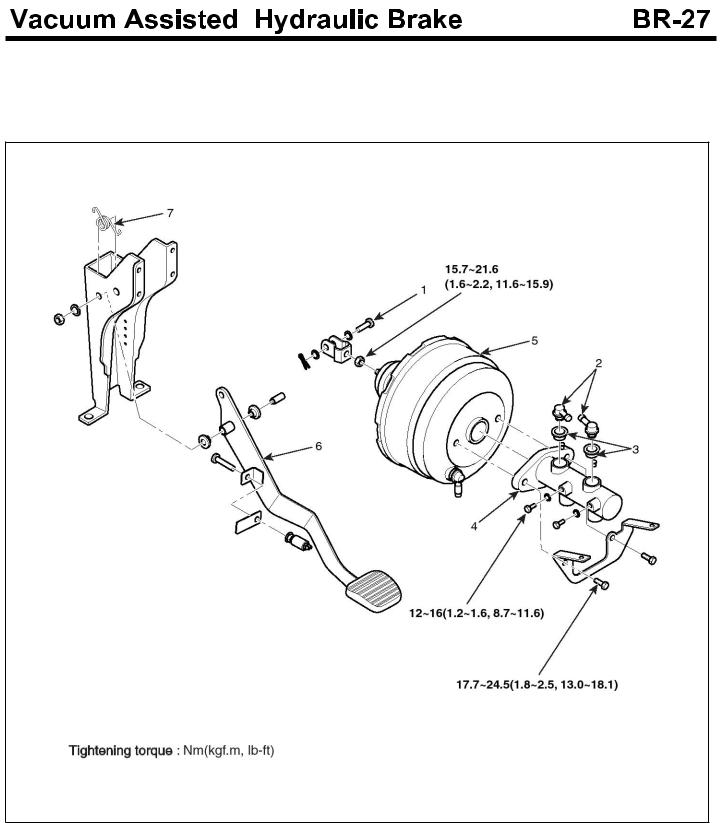
Component
SUDBRA003L
1. |
Clevis pin |
5. |
Booster |
2. |
Hose connector |
6. |
Pedal assembly |
3. |
Grommet |
7. |
Return spring |
4. |
Master cylinder |
|
|

Removal
1.Loosen the steering column assembly mounting bolt. Pull down the steering column.
2.Loosen the bolt(A), Remove the instrument panel(B).
KMTBR5003A
3.Remove the master cylinder (Refer to the BR-"Master cylinder")
4.Remove the brake booster (Refer to the BR-"Booster")
5.Remove the brake light switch.
6.Remove the shaft bolt(A) connected to the bracket.
KMTBR5040A
Installation
1.Install the brake pedal assembly(A) to the bracket(B).
 CAUTION
Before the assembling, apply the grease inside of the brake pedal assembly pipe.
KMTBR5527A
2.Install the brake light switch.
3.Install the booster and the master cylinder.
 CAUTION
Apply the grease on the clevis pin and the washer
Adjustment
Adjust the height of the brake pedal
1.Turn the booster operating rod so that the distance from the center of the brake pedal pad to the A point of the instrument panel lower portion is the 'B'. After adjusting, fix the clevis with the nut. Check that the maximum stroke of the pedal is more than 'C' (before filling the brake oil)
SUDBRA004L
|
Engine |
B(mm) |
C(mm) |
||
|
|
|
|
||
Non A- |
D4DD, D4GA |
± |
± |
||
280 |
2 |
140 |
4 |
||
BS |
|
|
|
||
The others |
± |
± |
|||
|
273 |
3 |
140 |
4 |
|
ABS |
D4DD, D4GA |
± |
± |
||
280 |
2 |
140 |
4 |
||
|
The others |
± |
± |
||
|
273 |
2 |
140 |
4 |
|
Free play clearance of the Brake pedal
1.Setting the brake pedal to the original position, check if the free play(B) clearance is 5mm at least by pressing the pedal(A).
If the clearance excesses the reference, re-adjust the position of the brake pedal.
 CAUTION
When checking the free play clearance of the brake pedal, the master back negative pressure should be 0.
KMTBR5005A
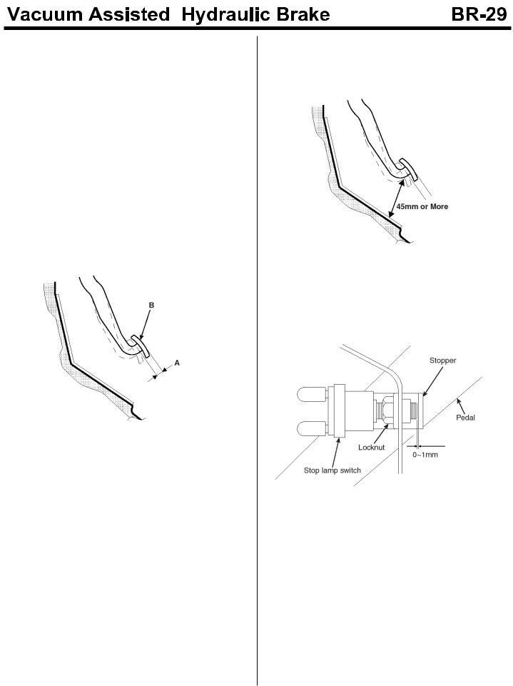
Gap between the brake pedal and the floor.
1.After cranking the engine, check if the gap between the floor and the pedal is more than 45mm by pressing the pedal with 50kg.
EMTBR5023A
Stop Lamp Switch
1.Adjusting the gap between the end of the brake. Stop lamp switch screw and the pedal stopper to 0~1mm, tighten the locknut.
SUDBR9014L

Brake Booster
Components
SUDBRA005L
1. |
Clevis pin |
5. |
Booster |
2. |
Hose connector |
6. |
Pedal assembly |
3. |
Grommet |
7. |
Return spring |
4. |
Master cylinder |
|
|
 Loading...