


Fuel System
General Information |
|
|
Specifications .................................................. |
FL - |
3 |
Troubleshooting ............................................... |
FL - |
5 |
Electronic Engine Control System |
|
|
Description ....................................................... |
FL -28 |
|
ECU |
|
|
Components............................................... |
FL -31 |
|
Removal ..................................................... |
FL -35 |
|
Mass Air Flow Sensor |
|
|
Inspection ................................................... |
FL -36 |
|
Differential Pressure Sensor(DPS) |
|
|
Components............................................... |
FL -39 |
|
Description ................................................. |
FL -39 |
|
Specifications ............................................. |
FL -40 |
|
Part Circuit Diagram .................................. |
FL -40 |
|
Replacement .............................................. |
FL -41 |
|
Electronic Fuel Supply System |
|
|
Components .................................................... |
FL -42 |
|
Injector |
|
|
Components............................................... |
FL -43 |
|
Removal ..................................................... |
FL -44 |
|
Installation .................................................. |
FL -45 |
|
Replacement .............................................. |
FL -45 |
|
Cleaning..................................................... |
FL -45 |
|
Common Rail Assembly |
|
|
Components............................................... |
FL -46 |
|
Removal ..................................................... |
FL -47 |
|
Installation .................................................. |
FL -47 |
|
Accelerator Pedal |
|
|
Description ................................................. |
FL -48 |
|
Removal ..................................................... |
FL -48 |
|
Inspection ................................................... |
FL -48 |
|
Fuel Tank And Fuel Filter |
|
|
Replacement .............................................. |
FL -49 |
|
Inspection ................................................... |
FL -50 |
|
Electronic Injection Pump |
|
|
Supply Pump |
|
|
Components............................................... |
FL -51 |
|
Removal ..................................................... |
FL -52 |
|
Installation .................................................. |
FL -53 |
|
DTC Troubleshooting Procedures
Basic Troubleshooting ..................................... |
FL -55 |
|
Schematic Circuit ............................................ |
FL -63 |
|
DTC List ........................................................... |
FL -80 |
|
P0072 ............................................................... |
FL -84 |
|
P0073 ............................................................... |
FL -88 |
|
P0088 ............................................................... |
FL -92 |
|
P0101 ............................................................... |
FL -98 |
|
P0102 ............................................................... |
FL -102 |
|
P0103 ............................................................... |
FL -106 |
|
P0107 ............................................................... |
FL -110 |
|
P0108 ............................................................... |
FL -112 |
|
P010A .............................................................. |
FL -114 |
|
P0112 ............................................................... |
FL -118 |
|
P0113 ............................................................... |
FL -122 |
|
P0116 ............................................................... |
FL -126 |
|
...............................................................P0117 |
FL -129 |
|
P0118 ............................................................... |
FL -132 |
|
...............................................................P0120 |
FL -135 |
|
P0121 ............................................................... |
FL -140 |
|
P0122 ............................................................... |
FL -145 |
|
P0123 ............................................................... |
FL -149 |
|
P0182 ............................................................... |
FL -153 |
|
P0183 ............................................................... |
FL -156 |
|
P0192 ............................................................... |
FL -159 |
|
P0193 ............................................................... |
FL -165 |
|
P0194 ............................................................... |
FL -171 |
|
P0195 ............................................................... |
FL -177 |
|
P0196 ............................................................... |
FL -183 |
|
P0201 ............................................................... |
FL -189 |
|
P0202 ............................................................... |
FL -195 |
|
P0203 ............................................................... |
FL -200 |
|
P0204 ............................................................... |
FL -205 |
|
P0217 ............................................................... |
FL -210 |
|
P0219 ............................................................... |
FL -212 |
|
P0220 ............................................................... |
FL -217 |
|
P0221 ............................................................... |
FL -222 |
|
P0222 ............................................................... |
FL -227 |
|
P0223 ............................................................... |
FL -232 |
|
P0225 ............................................................... |
FL -236 |
|
P0226 ............................................................... |
FL -240 |
|
P0237 ............................................................... |
FL -244 |
|
P0238 ............................................................... |
FL -249 |
|
P0335 ............................................................... |
FL -254 |
|
P0336 ............................................................... |
FL -259 |
|
P0340 ............................................................... |
FL -264 |
|
P0341 ............................................................... |
FL -269 |
|
P0401 ............................................................... |
FL -274 |
|
P0403 ............................................................... |
FL -277 |
|
P0404 ............................................................... |
FL -280 |
|
P0405 ............................................................... |
FL -284 |
|
P0406 ............................................................... |
FL -288 |
|
P0501 ............................................................... |
FL -292 |
P0502 ............................................................... |
FL -297 |
P0503 ............................................................... |
FL -302 |
P0541 ............................................................... |
FL -307 |
P0542 ............................................................... |
FL -309 |
P0562 ............................................................... |
FL -312 |
P0563 ............................................................... |
FL -315 |
P0601 ............................................................... |
FL -318 |
P0602 ............................................................... |
FL -320 |
P0603 ............................................................... |
FL -322 |
P0604 ............................................................... |
FL -324 |
P0606 ............................................................... |
FL -326 |
P0607 ............................................................... |
FL -328 |
P0615 ............................................................... |
FL -330 |
P0627 ............................................................... |
FL -333 |
P0629 ............................................................... |
FL -337 |
P0642 ............................................................... |
FL -341 |
P0643 ............................................................... |
FL -344 |
P0652 ............................................................... |
FL -347 |
P0653 ............................................................... |
FL -349 |
P0698 ............................................................... |
FL -351 |
P0699 ............................................................... |
FL -354 |
P069E .............................................................. |
FL -357 |
P069F ............................................................... |
FL -360 |
P0704 ............................................................... |
FL -363 |
P0850 ............................................................... |
FL -366 |
P1120 ............................................................... |
FL -369 |
P1132 ............................................................... |
FL -374 |
P1133 ............................................................... |
FL -377 |
P1190 ............................................................... |
FL -380 |
P1218 ............................................................... |
FL -384 |
P1219 ............................................................... |
FL -388 |
P1221 ............................................................... |
FL -391 |
P1222 ............................................................... |
FL -397 |
P1223 ............................................................... |
FL -400 |
P1231 ............................................................... |
FL -403 |
P1232 ............................................................... |
FL -406 |
P1383 ............................................................... |
FL -409 |
P1384 ............................................................... |
FL -411 |
P1616 ............................................................... |
FL -414 |
P1642 ............................................................... |
FL -419 |
P1643 ............................................................... |
FL -422 |
P2002 ............................................................... |
FL -425 |
P2146 ............................................................... |
FL -427 |
P2147 ............................................................... |
FL -432 |
P2148 ............................................................... |
FL -437 |
P2149 ............................................................... |
FL -442 |
P2150 ............................................................... |
FL -448 |
P2151 ............................................................... |
FL -453 |
P2293 ............................................................... |
FL -458 |
P2413 ............................................................... |
FL -462 |
P2454 ............................................................... |
FL -466 |
P2455 ............................................................... |
FL -471 |
P2503 ............................................................... |
FL -476 |
P2504 ............................................................... |
FL -478 |
U0001 .............................................................. |
FL -480 |
U0010 .............................................................. |
FL -483 |

General Information
SPECIFICATIONS
|
Items |
|
|
Specification |
|
|
|
|
|
|
|
Sensors |
BPS(Booster pressure sensor) |
Supply voltage |
5 V |
|
|
|
|
|
|
|
|
|
|
Operating voltage |
~ |
|
|
|
|
0.5 4.5 V |
|
||
|
|
Operating temperature |
~ |
° |
|
|
|
-40 125 C |
|
||
|
|
Operating pressure |
~ |
|
|
|
|
50 500 kpa |
|
||
|
|
Current |
MAX. 10 mA |
|
|
|
|
|
|
|
|
|
IAT(Intake air temperature) |
Type |
Thermistor |
|
|
|
|
|
|
|
|
|
|
Resistance |
~ |
° |
° |
|
|
2.31 2.56 kΩ [At 20 C(68 F)] |
|||
|
|
|
~ |
° |
° |
|
|
|
0.30 0.34 kΩ [At 80 C(176 F)] |
||
|
WTS(Water temperature sensor) |
Type |
Thermistor |
|
|
|
|
|
|
|
|
|
|
Resistance |
~ |
° |
° |
|
|
2.31 2.59 kΩ [At 20 C(68 F)] |
|||
|
|
|
~ |
° |
° |
|
|
|
0.314 0.331 kΩ [At 80 C(176 F)] |
||
|
TDC(Top dead center) sensor |
Type |
Hall sensor |
|
|
|
|
|
|
|
|
|
CKP(Crankshaft positon sensor) |
Type |
Magnetic |
|
|
|
|
|
|
||
|
APS(Accel positon sensor) |
Type |
Variable resistance(Potentiometer) |
||
|
|
|
|
|
|
|
|
Voltage |
5 V ± 1% |
|
|
|
|
|
|
|
|
|
|
Current |
Max. 10 mA |
|
|
|
|
|
|
|
|
|
Fuel pressure sensor |
Type |
Piezo electricity |
|
|
|
|
|
|
|
|
Actuator |
Injector |
Type |
Electromagnetic |
|
|
|
|
|
|
|
|
|
|
Resistance |
0.45 Ω |
|
|
|
|
|
|
|
|
Supply control valve |
SCV |
Current |
Active : Below 1.29 A |
|
|
|
|
|
|
||
|
|
|
When stopped :Below 1.16 A |
||
|
|
|
|
|
|
Fuel tank |
|
Capacity |
100 L |
|
|
|
|
|
|
||
Fuel pressure of high pressure side |
Max. pressure |
1,800 bar |
|
||
|
|
|
|
||
Supply pump |
|
Type |
Included into high pressure pump |
||
|
|
|
mechanical type |
|
|
|
|
|
|
|
|
|
|
Power |
Mechanical gear type |
|
|
|
|
|
|
|
|
Fuel filter |
|
Type |
Filter |
|
|
|
|
|
|
|
|

EGR Valve specification
Items |
Specification |
Valve type |
Flap type |
|
|
Control type |
Electric DC motor |
|
|
Sealant
Water temperature sensor(Coolant temperature sensor) |
Loctite 200 or equivalent |
|
|
Inspection
Item |
Reference value |
|
|
Idle speed(rpm) |
± |
650 25 |
Tightening torque
Items |
Kgf.m |
N.m |
lb-ft |
|||
|
|
|
|
|
|
|
ECM mounting bolt |
1.9 |
~ 2.8 |
18.6 |
~ 27.4 |
13.8 |
~ 20.4 |
|
|
|
|
|
|
|
Mass air flow sensor mounting bolt |
0.8 |
~ 1.2 |
7.8 ~ 11.8 |
5.8 |
~ 8.7 |
|
|
|
|
|
|
|
|
Crankshaft position sensor mounting bolt |
0.8 |
~ 1.2 |
7.8 ~ 11.8 |
5.8 |
~ 8.7 |
|
|
|
|
|
|
|
|
TDC sensor mounting bolt |
0.8 |
~ 1.2 |
7.8 ~ 11.8 |
5.8 |
~ 8.7 |
|
|
|
|
|
|
||
EGR valve mounting bolt(Inlet pipe) |
1.0 |
~ 1.4 |
9.8 ~ 13.7 |
7.2 ~ 10.1 |
||
|
|
|
|
|
||
EGR valve mounting bolt(EGR cooler) |
1.0 |
~ 1.4 |
9.8 ~ 13.7 |
7.2 ~ 10.1 |
||
|
|
|
|
|
|
|
High pressure pipe(rail-injector 1,2,3,4,5,6) |
4 |
~ 5 |
39 |
~ 49 |
29 |
~ 36 |
|
|
|
|
|
|
|
Common rail assembly mounting bolt |
1.9 |
~ 2.8 |
18.6 |
~ 27.4 |
13.8 |
~ 20.4 |
|
|
|
|
|
|
|
Fuel filler pipe assembly mounting bolt |
0.8 |
~ 1.2 |
7.8 ~ 11.8 |
5.8 |
~ 8.7 |
|
|
|
|
|
|
|
|
Fuel return pipe mounting bolt |
0.8 |
~ 1.2 |
7.8 ~ 11.8 |
5.8 |
~ 8.7 |
|
|
|
|
|
|
||
Fuel supply pump flange mounting bolt |
10 |
~ 13 |
98.6 ~ 128 |
72.3 ~ 94 |
||
|
|
|
|
|
|
|
Fuel supply pump mounting bolt |
1.9 |
~ 2.8 |
18.6 |
~ 27.4 |
13.8 |
~ 20.4 |
|
|
|
|
|
||
Injector clamp bolt |
2.9 |
~ 3.1 |
28.42 ~ 29.4 |
21 ~ 22.4 |
||
|
|
|
|
|
|
|

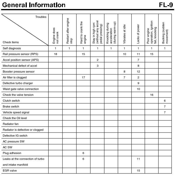
TROUBLESHOOTING
Symptom |
Possible causes |
Remedy |
Engine does not crank. |
Low cranking speed |
Repair the starter or charge or replace b- |
|
attery. |
|
|
|
|
|
|
|
|
Low voltage to glow plug system |
If the test light turns on indicating low vo- |
|
|
ltage when it turns “ON”, check relay and |
|
|
wiring. |
|
|
|
|
Defective glow plug |
Replace the glow plug. |
|
|
|
|
Air in the fuel system |
Air bleeding of fuel system |
|
|
|
|
Injection pipe is connected incompletely. |
Connect the pipe correctly |
|
|
|
|
Improper injection timing |
Check ECM. |
|
|
|
|
Poor injection |
Check, replace injector. |
|
|
|
|
Mechanical defect of engine |
Test compression, repair engine. |
|
|
|
|
Simultaneous failures of TDC sensor and |
Check and tighten correctly. |
|
CKP sensor |
|
Idle is improper or idle speed is u- |
Loose fuel hose connection between filt- |
Tighten or repair. |
nstable or irregular. |
er and supply pump. |
|
|
Air in the fuel system |
Air bleeding of fuel system |
|
|
|
|
Fuel filter is clogged. Or fuel supply is no |
Check hose or fuel line. Replace fuel filt- |
|
good because fuel line or injection pipe l- |
er if necessary. |
|
eaks, pinched or pressed. |
|
|
|
|
|
Poor injection |
Check, replace injector. |
|
|
|
|
Improper injection timing |
Check ECM. |
|
|
|
|
Mechanical defect of engine |
Test compression, repair engine. |
|
|
|
|
Defective supply pump |
Let the engine at idle after replacing pu- |
|
mp. |
|
|
|
|
|
|
|
|
Engine defect at high gear range |
Observe correct shift speed. |
|
|
|
|
EGR valve malfunction |
Check or replace EGR valve. |
|
|
|
Exhaust gas (Black, blue, white) |
Engine temperature stays below engine |
Check cooling system. Replace thermos- |
|
operating temperature. |
tat. |
|
|
|
|
Abnormal at max. RPM |
Check and replace supply pump. |
|
|
|
|
Defective Injection nozzle |
Check and repair or replace. |
|
|
|
|
Improper injection timing |
Check ECM. |
|
|
|
|
Exhaust system malfunction |
Check for deformed or clogged. |
|
|
|
|
Mechanical defect of engine |
Test compression, repair engine. |
|
|
|
|
Defective supply pump |
Replace supply pump. |
|
|
|
|
EGR valve malfunction |
Check or replace EGR valve. |
|
|
|

Symptom |
Possible causes |
Remedy |
|
|
|
|
|
Engine lacks power, acceleration i- |
Abnormal at max. RPM |
Check, replace supply pump. |
|
s delayed(Speedometer is normal, |
|
|
|
Contaminated air cleaner filter |
Clean or replace. |
||
no clutch slip) |
|
|
|
Fuel filter is clogged. Or fuel supply is no |
Check hose or fuel line. Replace fuel filt- |
||
|
|||
|
good because fuel line or injection pipe l- |
er if necessary. |
|
|
eaks, pinched or pressed.Or fuel filter le- |
|
|
|
aks. |
|
|
|
|
|
|
|
Air in fuel system |
Air bleeding of fuel system |
|
|
|
|
|
|
Defective supply nozzle |
Check, repair or replace. |
|
|
|
|
|
|
Improper injection timing |
Check ECM. |
|
|
|
|
|
|
Mechanical defect of engine |
Test compression, repair engine. |
|
|
|
|
|
|
Defective injection pump |
Check after replacing pump. |
|
|
|
|
|
|
EGR valve malfunction |
Check, replace EGR valve. |
|
|
|
|
|
Excessive fuel consumption |
Contaminated air cleaner filter |
Clean, replace air cleaner filter. |
|
|
|
|
|
|
Fuel leaks |
Check all pipes, hoses and connection. |
|
|
|
Replace or tighten as required. |
|
|
|
|
|
|
Clogged return pipe and hose. |
Check and replace the return line, blow |
|
|
|
air if clogged and drain the fuel. |
|
|
|
|
|
|
Defective injection nozzle |
Check. Repair or replace. |
|
|
|
|
|
|
Mechanical defect of engine |
Compression test, replace engine. |
|
|
|
|
|
|
Defective supply pump |
Replace pump. |
|
|
|
|
|
|
EGR valve malfunction |
Check or replce EGR valve. |
|
|
|
|
Engine control
Symptom |
Possible causes |
Remedy |
|
|
|
Engine will not turn off. |
Injector wiring short |
Check injector wiring. |
|
|
|
|
Starting switch harness is damaged. |
Replace. |
|
|
|

Engine starting system
Symptom |
Possible causes |
Remedy |
|
Engine does not crank |
Low battery voltage |
Recharge or replace the battery. |
|
|
|
|
|
|
Battery cable connection is loose, corro- |
Replace or retighten. |
|
|
ded or worn. |
|
|
|
Fusible link is swelled. |
Replace the fusible link. |
|
|
|
|
|
|
Defective starter motor. |
Repair. |
|
|
|
|
|
|
Defective injector |
Replace. |
|
|
|
|
|
Cranking speed is low |
Low battery voltage |
Recharge or replace the battery. |
|
|
|
|
|
|
Battery cable connection is loose, corro- |
Repair or replace. |
|
|
ded or worn |
|
|
|
|
|
|
|
Defective starter motor |
Repair |
|
|
|
|
|
Starter motor continues to run. |
Defective starter motor |
Repair |
|
|
|
|
|
|
Defective ignition switch |
Replace the ignition switch. |
|
|
|
|
|
Starter motor runs but engine is n- |
Defective wiring |
Repair wiring. |
|
ot cranking. |
|
|
|
Starter motor, pinion gear damaged |
Repair starter motor. |
||
|
|||
|
|
|
|
|
Ring gear damaged |
Replace flywheel or torque converter ge- |
|
|
|
ar. |
|
|
|
|
Fuel tank and fuel line
Symptom |
Possible causes |
Remedy |
|
|
|
|
|
Poor engine performance due to i- |
Fuel pipe is twisted or bended |
Repair or replace. |
|
nsufficient fuel supply |
|
|
|
Fuel pipe or hose is clogged |
Clean or replace. |
||
|
|||
|
|
|
|
|
Fuel filter is clogged |
Replace. |
|
|
|
|
|
|
Entry of water to fuel filter |
Replace fuel filter or clean fuel tank or f- |
|
|
|
uel line. |
|
|
|
|
|
|
Foreign materials intrude in fuel tank. |
Clean or replace. |
|
|
Fuel tank rusts. |
|
|
|
|
|
|
|
Defective supply pump operation |
Replace. |
|
|
(Clogged filter in pump) |
|
|
|
|
|
|
Fuel filter warning lamp blinks. |
Excessive water is in fuel filter. |
Drain the water collected in the fuel filter |
|
|
|
(Loosen the drain plug at the bottom of f- |
|
|
|
uel filter.) |
|
|
|
|
|
Engine check lamps blinks. |
Clogged fuel filter. |
Replace fuel filter. |
|
|
|
|

Troubleshooting procedure
SDGFL9001L
SUDFL9001L

SUDFL9002L
SDGFL9004L
SERVICE PROCEDURE
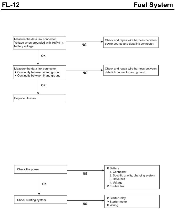
Communication with diagnosis equipment is not possible
(Impossible communication with all systems)
SDGFL9005L
When communication between diagnosis equipment and
ECM is not possible
Trouble symptoms |
Probable causes |
It shows at least one of the following symptoms. |
|
When power is not supplied to ECM, |
Power supply circuit to ECM is defective.ECM |
ECM ground circuit is defective. |
|
Defective ECM |
Malfunction ECM |
Wrong communication line between ECU and Hi-scan |
Circuit between ECU and DLC is open. |
|
|
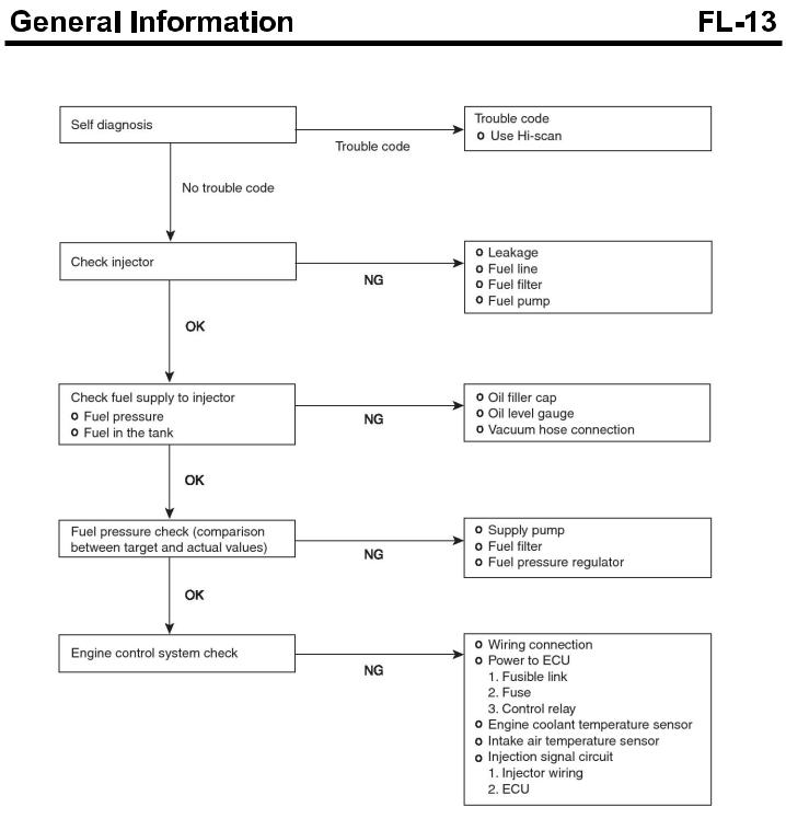
Engine does not start.
SDGFL9006L
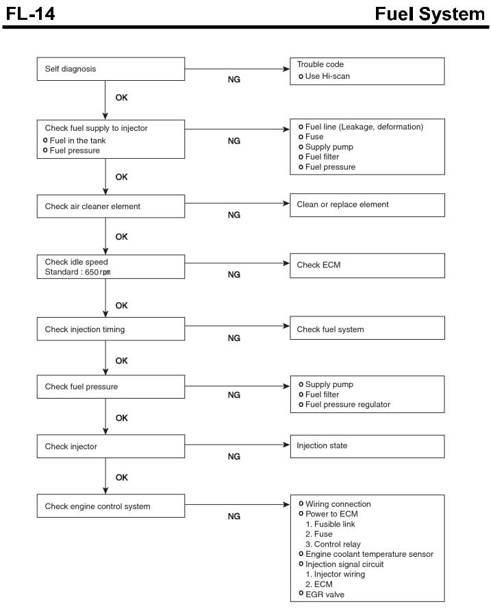
It is difficult to start the engine. (Possible cranking)
SDGFL9007L
Unstable idle or engine stall.
SUDFL9003L
Engine hesitation or poor acceleration
SDGFL9009L
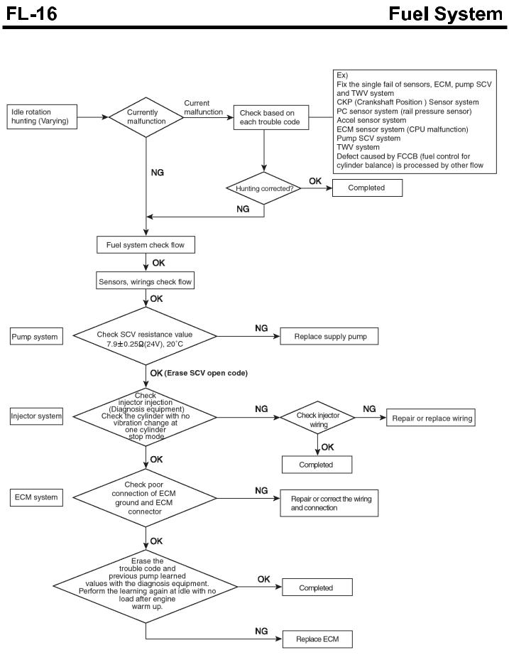
Troubleshooting flow chart when HUNTING(Varying) occurs
SUDFL9004L
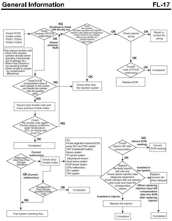
Troubleshooting flow chart when FCCB(Fuel control cylinder balance) fails.
SUDFL9005L

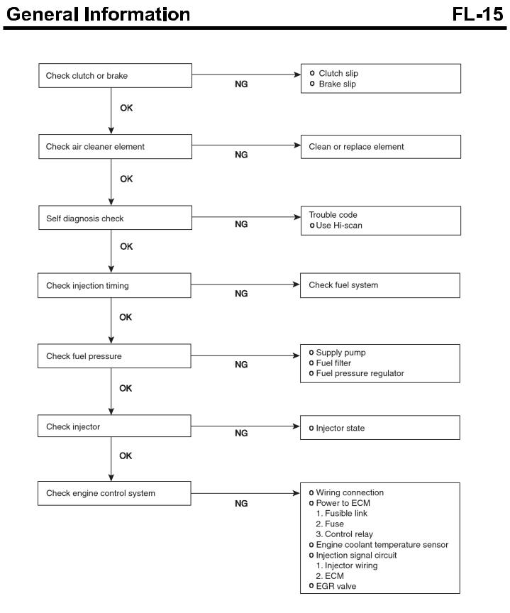
Troubleshooting flow chart when engine is lack of power
SUDFL9006L
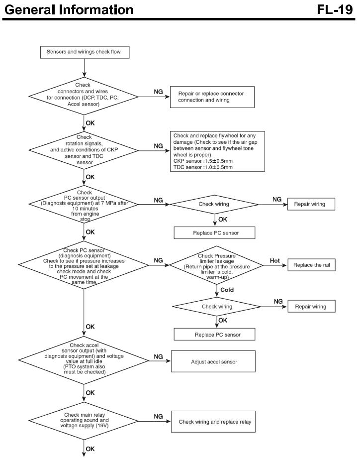
Troubleshooting flow chart in systems of sensors and wirings
SDGFL9013L

CRS RAIL PRESSURE CHECK
■Items to check in the vehicle
1.Check for customer complaint and trouble symptoms.
2.Check reoccurrence or not for customer complaint and trouble symptoms mentioned above.
3.Record DTC codes or record the detailed DTC codes by using Hi-scan.
Inspect and repair causes due to DTC codes.
4.Check rail pressure when turning ignition key to NO(Engine OFF).
If the rail pressure is displayed, check it according to inspection procedure of remaining pressure.
5.Check for connector of rail pressure sensor.
Check for wiring tension between rail pressure sensor and connector of vehicle side.
Check that wiring between rail pressure sensor and connector of vehicle side is tight or not due to vibration(under driving) with interference in bracket of engine/vehicle etc.
Check rail pressure sensor wire for clamp conditoin.
Check that wire of rail pressure senor is clamped securely or not.
Check rail pressure sensor and connector of vehicle side for connection conditon.
With connector connected, check connector for shaking(with right and left/ back and forth).
If there is free play, check for output of rail pressure/rail pressure sensor using Hi-scan or oscilloscope.
6.Check for wiring related to the output of rail pressure sensor.
Check for voltage between each terminal of rail pressure sensor in the ECM side and terminal (-) of battery.
Check wire between rail pressure sensor and ECM for continuity(resistance).
7.Visual check of connector
Check each terminal contact part of rail pressure sensor for wear.
Check connector housing of rail pressure sensor for wear.
Check locking part/ guide part of rail pressure sensor connector for damage or deformation.
Check the inside of rail pressure sensor connector for foreign materials(such signs as water, oil, spark, tracking etc.).
Check the opposite connector for foreign materials, wear, damage, existence or not of rubber seal or shrinkage of rubber seal etc..
SDGFL9014L
Rail pressure sensor |
|
Voltage check |
|
Check wiring between rail pres - |
||
terminal |
|
|
sure sensor and ECM |
|||
|
|
|
||||
|
|
|
|
|
|
|
|
|
|
|
Measured v - |
|
|
Item |
Pin No. |
Check condition |
ECM terminal side r - |
alue noise |
Reference value/me - |
Measured |
|
|
|
eference value |
or |
asured condition |
value |
|
|
|
|
not |
|
|
Vc |
E68 |
Key On |
~ |
|
Below 2[ohm]/Key Off |
|
4.9 5.1 |
|
|
||||
|
|
Key On/EngineOff |
~ |
|
Below 2[ohm]/Key Off |
|
Vout |
E32 |
0.9 1.1 |
|
|
||
Engine On/at Accel. |
Refer to illustration 3 |
|
Below 2[ohm]/Key Off |
|
||
|
|
|
|
|||
|
|
|
|
|
|
|
|
|
Key On/Engine Off |
~ |
|
Below 2[ohm]/Key Off |
|
Vout |
E13 |
0.9 1.1 |
|
|
||
Engine On/at Accel. |
Refer to illustration 3 |
|
Below 2[ohm]/Key Off |
|
||
|
|
|
|
|||
|
|
|
|
|
|
|
GND |
E25 |
Key On |
± |
|
Below 2[ohm]/Key Off |
|
0 0.1 |
|
|
||||

CRS Rail pressure check flow chart
SDGFL9015L

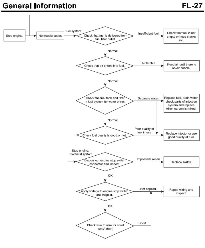
Fuel system check processor
SUDFL9007L

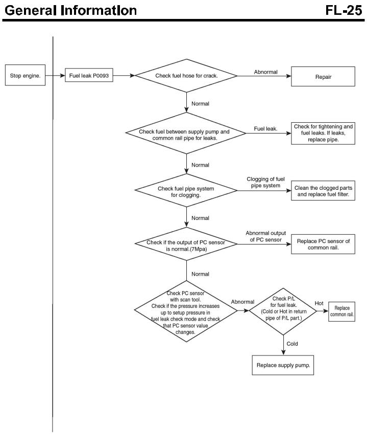
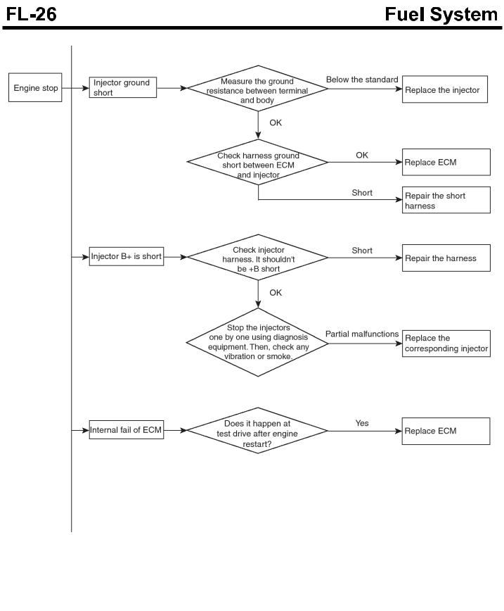
Troubleshooting flow chart when the engine stops
SUDFL9008L
SUDFL9009L
SDGFL9019L
SUDFL9010L
Electronic Engine Control System
DESCRIPTION
DIESEL CONTROL SYSTEM Inspection of the diesel control system
If the components of the diesel control system (sensor, ECM, injector etc.) have a problem, the proper amount of fuel for various engine-operating conditions can not be supplied and also the following situations can occur.
1.It is hard to start the engine or does not start the engine at all.
2.Idling is unstable.
3.Engine driving performance is bad.
If any of the above conditions are met, first perform a routine diagnosis that includes basic engine checks (ignition system malfunction, incorrect engine adjustment etc). Then, inspect the components of the diesel control system with multi-purpose tester or digital multi-meter.
 CAUTION
Before removing or installing any part, read the diagnostic trouble codes and then, disconnect the battery negative (-) terminal.
Before disconnecting the cable from battery terminal, turn the ignition switch to OFF. If the battery cable is removed or connected during engine operation or the situation in which the ignition switch is ON, then the ECU semiconductor could be damaged resulting in inaccurate operation.
Self-diagnosis
The ECM sends the input/output signals to various parts of engine(some signals at all times and the others under specified conditions).
After the specific time elapses the first detection of irregular signal, the ECU judges this as an irregularity and it records the diagnostic trouble code. And then it sends the signal to the self-diagnosis output terminal. The diagnosis results can be checked by the Hi-scan. In addition, Diagnostic Trouble Codes (DTC) will be directly backed up by the battery so that it will remain in the ECM even if the ignition switch is turned off. The diagnostic trouble codes will, however, be erased when battery terminal or ECM connector is disconnected.
 CAUTION
If, in most of diesel control system, the connector of a sensor is disconnected with the ignition switch turned ON, the diagnostic trouble code (DTC) is recorded in the ECM. In this case, if the battery
negative terminal (-) is disconnected for 15 seconds or more, then the diagnosis memory will be erased.
Self-diagnosis check procedure
 CAUTION
As DTC code may not be detected due to low battery voltage, the battery condition should be checked prior to inspection.
Since DTC code is erased if the battery or the ECM connector is disconnected, don't disconnect the battery until the diagnostic trouble codes are completely read and recorded safely.
It is most desirable to erase the diagnostic trouble codes using Hi-scan after completing check and repair. After disconnecting ground cable from the battery negative (-) terminal for 15 seconds or more, reconnect the cable and check if the trouble codes have been erased. (At this time, ignition switch must be turned off).
Inspection procedure (Using Hi-scan)
1.Turn off the ignition switch.
2.Connect the Hi-scan connector to the connector of DLC (Data Link Connector) for the trouble diagnosis as shown in the figure.
3.Turn the ignition switch ON.
4.Check the diagnostic code using Hi-scan.
5.Repair the parts having faults shown in the diagnosis chart.
6.Erase the diagnostic trouble codes.
7.Disconnect the Hi-scan.
KDDFL5019A
 NOTICE
When using a tester manufactured by other company, operate the tester by referring to the manual of the company.
When erasing the diagnostic trouble codes, use Hi-scan if possible. Though DTC can be erased by disconnecting the battery terminal, doing so, the data for learning control in ECM would be erased at the same time.
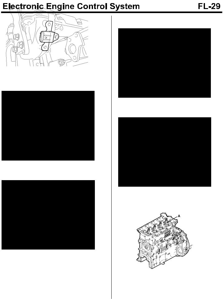
DIESEL CONTROL SYSTEM COMPONENTS LOCATION
1.Intake air temperature sensor and intake air pressure sensor
SDFFL7503D
2. Crankshaft position sensor
SDFFL7504D
3.Water temperature sensor(Coolant temperature sensor)
SDFFL7505D
4. Camshaft sensor
SDFFL7506D
5. Injector(A)
SDFFL7009D
6. Rail pressure sensor(A)
SDFFL7006D
7. Supply control valve(SCV, A)
SDFFL7007D
8. ECM(Engine control module, A)
SDFFL7008D
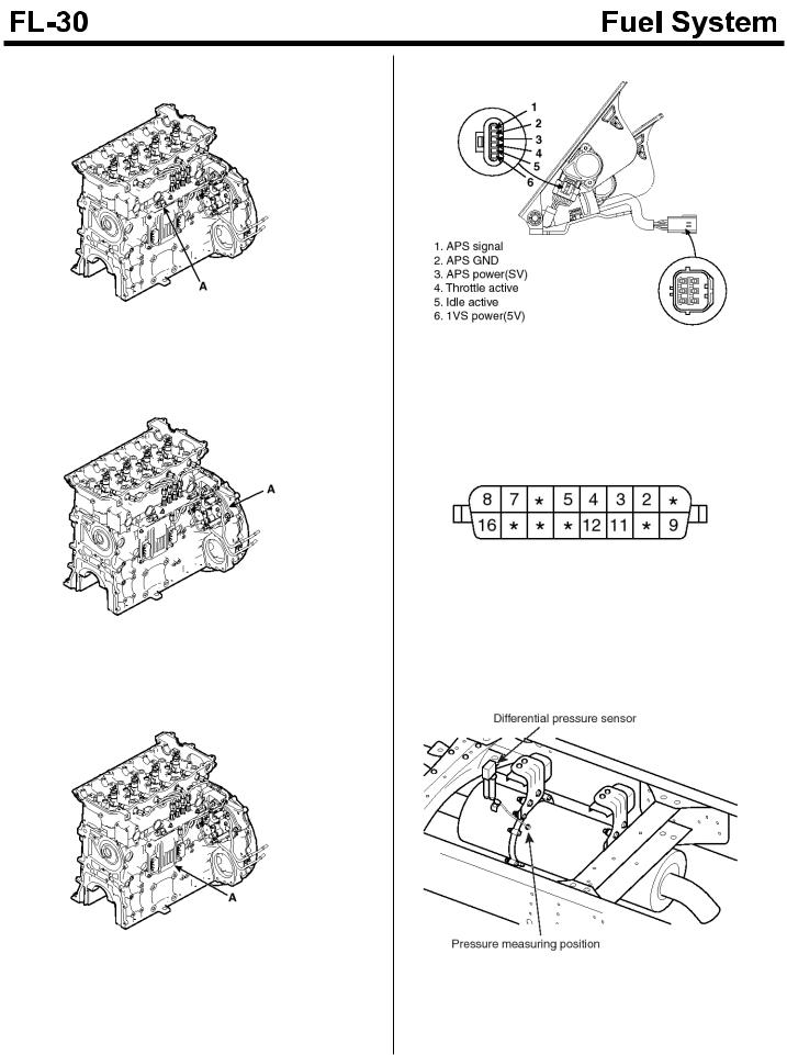
9. Accelerator position sensor
SUDFL9016L
10.DLC connector
SDFFL7314D
11.DPS(Differential Pressure Sensor)
SUDFLDTC9108L
 Loading...