

For Husqvarna Parts Call 606-678-9623 or 606-561-4983
HOME PRODUCTS
2002 SERVICE
UPDATE INFORMATION
www.mymowerparts.com

For Husqvarna Parts Call 606-678-9623 or 606-561-4983
NOTES
2
www.mymowerparts.com

For Husqvarna Parts Call 606-678-9623 or 606-561-4983
TABLE OF CONTENTS
Steering changes for Lawn Tractors 4
Fuel Tanks / Seat inprovements 6
Brake Adjustments 7
DLT Transmission installation / Freewheel Rod/ Control Linkage 8
DLT reverse Pedal / LT Belt Guide / GT Assist Spring change 9
Electrical Components Improvements 10
Electrical Components Quick Reference 11
Tractor Electricdal Troubleshooting Basics 12
Tiller Improvements 17
48” Mower Baffle 18
48” Deflector / Blade Bolt Torque / Nose Roller Kit 19
Changes to the Two Bin Bagger 20
EZ Walk Mowers - Drive Cable Adjustment 21
EZ Walk Drive Pinion 22
EZ Walk Drive Pinion - Gearbox - Blade Adapter 23
EZ Walk Drive Cable Replacement 24
EZ Walk Drive Belt Replacement 26
HONDA Blade Brake Clutch 27
Changes to: Electric Start - Grass Catcher - Drive Wheels 28
Changes to: High Wheel Trimmers - Front Gear Drive Mowers 29
Blade List 30
3
www.mymowerparts.com
For Husqvarna Parts Call 606-678-9623 or 606-561-4983
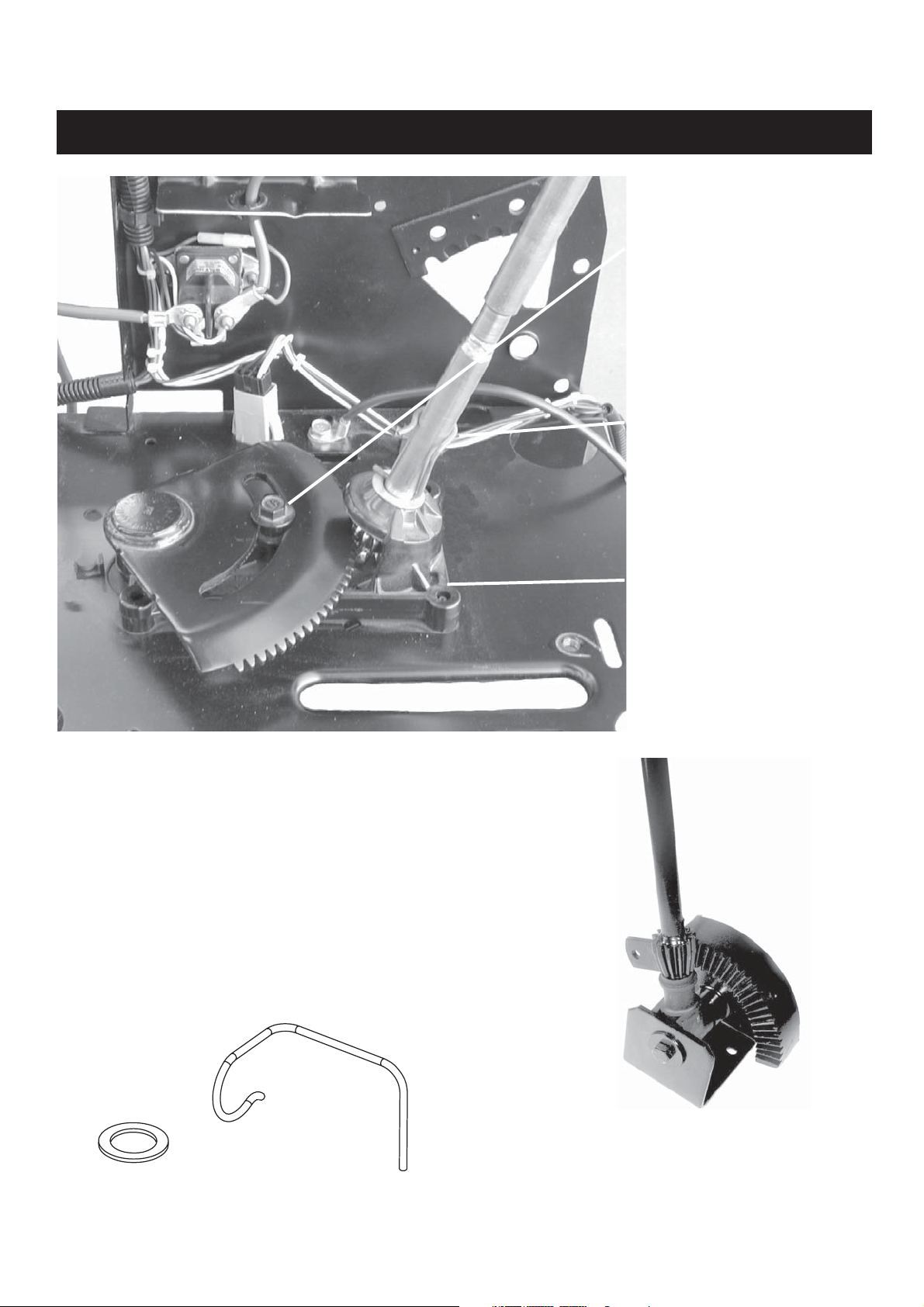
NEW LAWN TRACTOR STEERING
ASSEMBLY MOUNT
STEERING CLIP
A new steering system was phased in during 2001
on lawn tractors. The new steering system is
smoother and requires less effort to turn the steering wheel. The assembly mount is held by four
self tapping screws from the underside. A washer
is placed on the steering shaft and is retained by
the steering clip.
NOTE: The new steering cannot be used to replace the old steering system because the chasis
are made differently.
STEERING CLIP
GEAR SHOULDER BOLT
OLD STEERING
ASSEMBLY
4
www.mymowerparts.com
For Husqvarna Parts Call 606-678-9623 or 606-561-4983
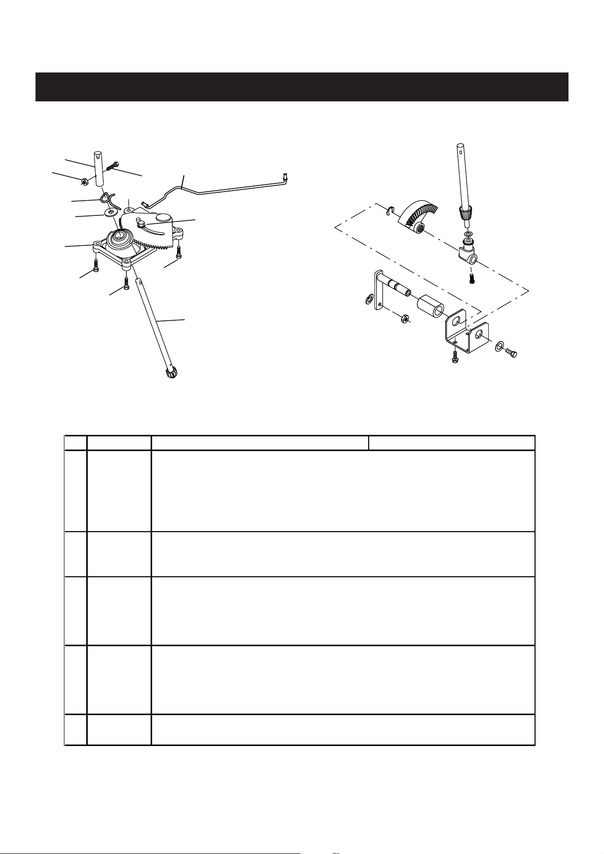
NEW LAWN TRACTOR STEERING
NEW STEERING
8
10
3
4
1
5
5
9
6
2
5
7
OLD STEERING
Replaces this Steering System on Lawn
Tractors
PARTS FOR NEW LAWN TRACTOR STEERING
Key Part Num ber
1 175146
2 175118
3 175553
4 121749X
5 17060612
5 17060616
6 175121
6 175122
7 177876
8 153720
9 74780520
10 73800500
7 180641
8 180640
9 71130420
10 73540400
ASY - MOUNT - complete Requires 175118
BOLT-SHOULDER-GEAR NOT included with 175146
CLIP, Steering - Spring - 3/4"
WASHER .781ID X 1.0OD X 16GA
SCREW, 3/8 -16 X 3/4" Self Tapping
SCREW, 3/8 -16 X 1.0" Self Tapping Also mounts drive belt keeper
DRAGLINKS used with new LT Steering
DRAGLINK - 15" FRONT WHEEL .LT.2001
DRAGLINK - 16" FRONT WHEEL .LT.2001
MY2001 Steering Parts used with LT HOOD
Shaft-Assembly - 17.8" LENGTH - Thru-hole dia .331
EXTENSION-STEERING, uses bolt - 3/8-16 threaded hole
5/16-18 X 1.25" Bolt GR 8
5/16-18 HEX LOCKNUT
MY2002 Steering Parts used with LT HOOD
Shaft-Assembly - 17.8" LENGTH - End with dia .265 thru hole
EXTENSION-STEERING, uses locknut - Double D with 1/2-20 Threaded End
1/4-28 X 1.25" Bolt - Grade 8
1/4-28 NUT Crown Lock
Description Notes
7 177883
Steering Parts used with STEALTH / DLT / LARGE HOOD
Shaft Steering - 23.4" LENGTH - Double D with 1/2-20 Threaded End
5
www.mymowerparts.com

For Husqvarna Parts Call 606-678-9623 or 606-561-4983
LARGER FUEL TANKS ON DELUXE MODELS
New
larger
Fuel
Cap
The Operator can view the fuel level in rear tank
through the fender for 2002. Garden Tractors will
have 5 gallon tanks. DLT models will have 4
gallon rear tanks.
NEW SEAT MOUNTING
OLD STYLE
SEAT
(2001 & Before)
ONE SLOT
NEW SEAT
SHOULDER
BOLTS
There will be a transition to a new seat system this year. The new seat will have two shoulder bolts that
will slide in two slots in a new wider seat pan. Because of the wider seat pan, the seat pivot bracket will
be wider. The old seat pan had one slot and two tracks allowing the seat to slide forward and backward.
6
www.mymowerparts.com
For Husqvarna Parts Call 606-678-9623 or 606-561-4983
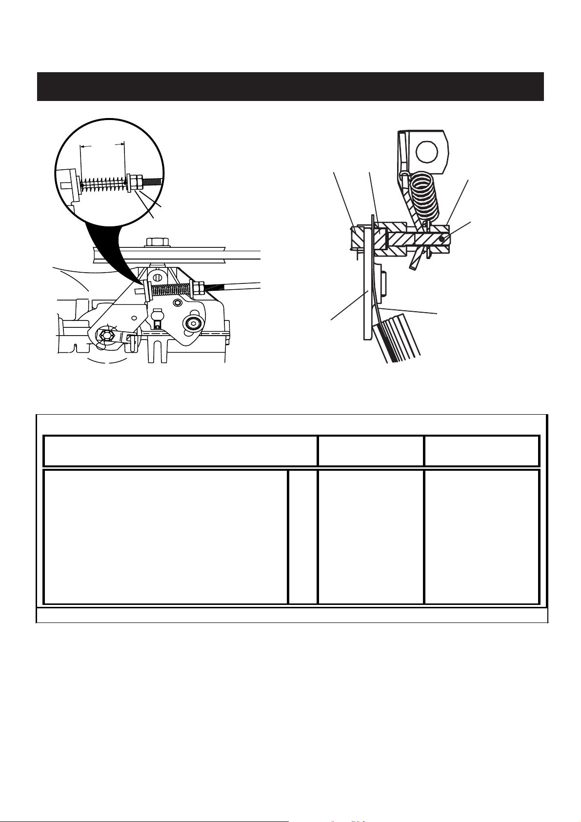
TRACTOR BRAKE ADJUSTMENTS
Spring
Dim
Jam Nut
Nut
Brake
Disc
Brake Disc
Engage Parking Brake and check the
Brake Spring Dimension.
Use feeler gauge to set Puck Clearance at
recommended dimension.
BRAKE ADJUSTMENT DIMENSIONS
TRANSMISSION
Brake Pucks
SPRING
DIMENSION
Castle Nut
Use new
Cotter Pin
Feeler Gauge
PUCK
CLEARANCE
P eerless M ST LT 1 1/2" .015"
DAN A 4360 LT 1 1/2" .020"
Hydro G ear 0510 P CA LT 1 3/4" .015"
Hydro G ear 0510 LCA LT 1 9/16" .015"
Hyrdo Gear 0510 CRD LT 1 11/16" .015"
Hydro G ear 0500/0650/0750 * LT 1 9/16" .020"
EHP XHD Hi-Lo Range GT 1 3/4" .015"
Hydro G ear 3010L G T 1 1/2" .020"
Hydro G ear 3000 / 3500 GT
PCA = Pedal Controlled Automatic LCA = Lever Controlled Autom atic
NOTE: Any time you do anything with the brake, the brake must be tested. The tractor must stop within six ( 6 ) feet on a
level paved surface from the fastest speed. Test the tractor to hold itself on a 15 degree slope with the parking brake.
If the brake does not pass tests, the brake puck clearance must be adjusted tighter. There is a slope guide in the tractor
owners manuals.
NOTE: If excessive wear is found on the brake disc or the brake pucks, these parts should be replaced before adjustments are made. Use a new cotter pin to lock the castle nut after adjustment.* HG 0500-0650-0750 insert the feeler
guage between the brake rotor and stator rings from underneath. Be sure to fully insert the gauge through the lower and
then the upper part of the rotor and stator rings.
Not Adjust
.015"
7
www.mymowerparts.com
For Husqvarna Parts Call 606-678-9623 or 606-561-4983
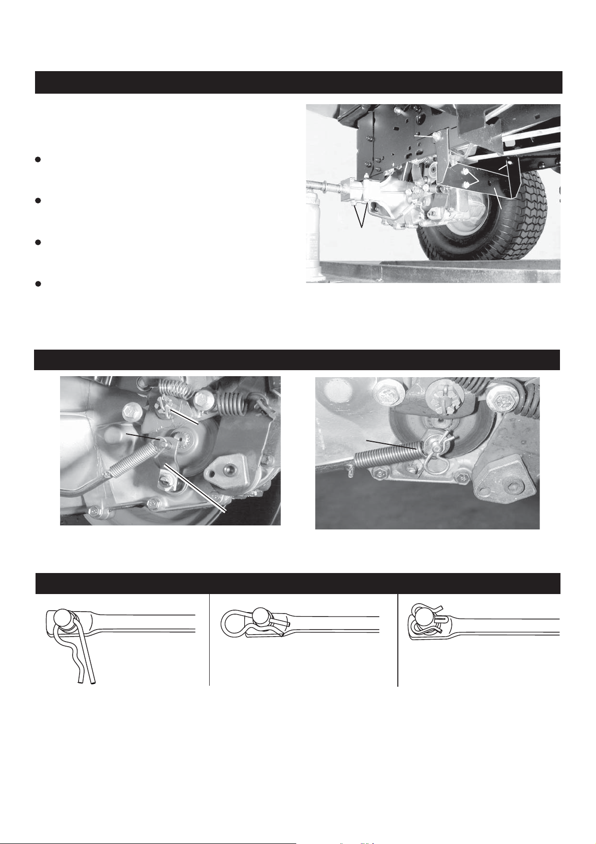
DLT PEDAL AUTOMATIC REVERSE COMPLAINTS
DLT tractors with Pedal Control Automatic may
have complaints of slow reverse or no reverse
if the correct installation procedure is not used.
Tighten fasteners in this sequence:
Loosely assemble all screws or bolts
and nuts that hold transaxle.
Tighten the screws labeled 1 that hold
the transaxle to the Torque Strap.
3
Tighten the screws labeled 2 that hold
the Torque Strap to the Chasis.
Tighten the nuts and bolts labeled 3
that hold the axle supports to the rear
mounting brackets.
NOTE: If this procedure does not increase the reverse speed. Use a straight edge to check the Torque
Strap. If there is a severe bow toward the rear, the transaxle is located too far rearward.
2
2
1
TORQUE
STRAP
DLT FREEWHEEL CONTROL ROD
2001
FREEWHEEL
ROD SPRING
The attachment of the spring on the Freewheel Control Rod to the Bypass Valve has been improved on
DLT tractors. The end of the spring is formed differently and a 179422 washer and 4497H retainer
spring now retain it to the Bypass Valve.
CASTLE NUT
BYPASS
VALVE
2002 DLT
FREEWHEEL
ROD SPRING
DLT AUTOMATIC PEDAL LINKAGE
IMPROPER
INSTALLATION
PROPER
INSTALLATION
NEW 178062 CLIP
The linkage going from the Foot Pedals to the Automatic Transaxle control arm was retained with 4497H
Retainer Springs. If improperly installed, the 4497H can keep the linkage from the full range of
movement needed. The tractor may not go as fast in forward or reverse as it can. In 2002 a change is
made to a 178062 Clip so it cannot be installed improperly.
8
www.mymowerparts.com
For Husqvarna Parts Call 606-678-9623 or 606-561-4983
DLT REVERSE PEDAL IMPROVEMENT
The 179433 Reverse Pedal now comes with the
Pedal , Pedal Cover, and the Screw installed. One
shoulder bolt under the footpad can be removed
and used to install a new reverse pedal
assembly.
REVERSE
PEDAL
SHOULDER
BOLT
LT BELT GUIDE CHANGES
Changes have been made to improve the belt guide
on the 6 speed lawn tractor transaxles. The guide
is now closer to the pulley to better retain the belt
and improve belt disengagement characteristics.
To identify the belt guides, the loop for the screw
that retains the belt guide is in the reverse
direction on the 178394. The previous number was
173898.
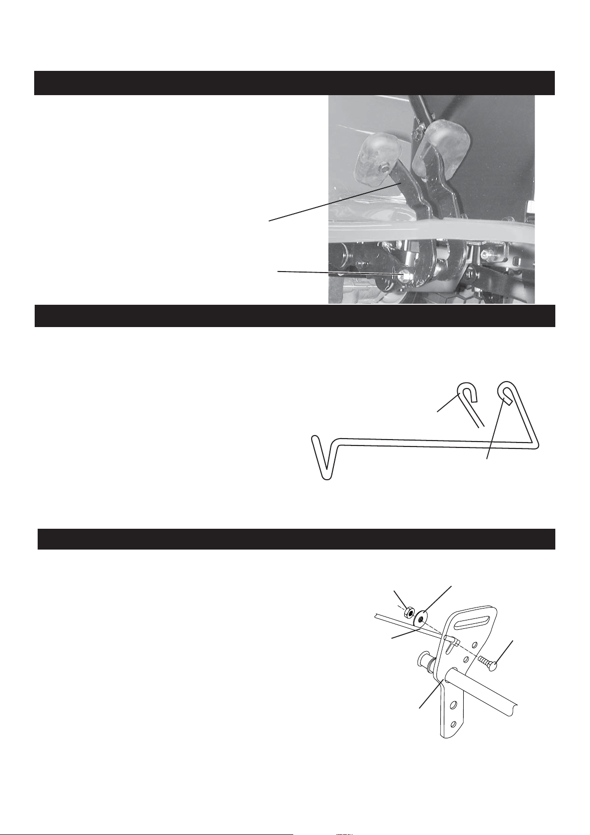
GARDEN TRACTOR LIFT ASSIST SPRING CHANGE
The Lift Assist Spring Assembly on Garden
Tractors will now be part of the Sleeve Hitch Kit,
beginning in 2002. A slot has been added to the
bracket on the Lift Shaft. The end of the spring is
hooked into the slot . A bolt, nut , and washer are
then installed to hold the assist spring in the proper
position. The bracket at the other end of the spring
will need to be attached to the chasis. Complete
instructions will be included in the Sleeve Hitch
Kit.
LOOP ON PREVIOUS
173898 BELT GUIDE
LOCK NUT
FORWARD END
OF LIFT ASSIST
SPRING
LIFT SHAFT ASSEMBLY
178394 BELT GUIDE
FLAT WASHER
CARRIAGE
BOLT
9
www.mymowerparts.com

For Husqvarna Parts Call 606-678-9623 or 606-561-4983
ELECTRICAL COMPONENT IMPROVEMENTS FOR 2002
A lock tab is added to snap in Interlock
Switches for 2002. The new switch will
work for the switches without a tab.
176137 S
176138 SWITCH NO-NC GRAY
A new interlock switch at the footpedal will be used
with tractors equipped with POWERLINK. It is
part # 181884. This is a NO-NO-NO switch. The
additional set of contacts are needed so that
POWERLINK cannot function unless the Parking
Brake is engaged.
The reset switch used with POWERLINK is a part
# 110712X. This switch was used in the past as a
tractor headlight switch.
WITCH NO-NO BLACK / GRAY
SWITCH
CONNECTOR
PREVIOUS
STYLE
LOCK
TAB
There will be a new Battery Box 176689 under the
seat on lawn tractors. Where this battery box is
used, a 180499 Battery Terminal Cover must be
installed where the red battery cable attaches to
the positive battery terminal.
Snap in retainers will be attached to the electrical
harness to give more places where the harness is
held to the chasis.
10
www.mymowerparts.com
 Loading...