

Page 1
For Husqvarna Parts Call 606-678-9623 or 606-561-4983
SECTION 1. DESCRIPTION AND OPERATION
A fixed displacement gerotor charge pump is pro-
INTRODUCTION
The purpose of this manual is to provide information useful in servicing the Hydro-Gear Bantam Duty Pumps (BDP’s). This manual includes
the BDP’s general descriptions, hydraulic schematics, technical specifications, servicing and
troubleshooting procedures for BDP models 10A
and 21L.
The BDP’s normally will not require servicing during the life of the vehicle in which it is installed.
Should other servicing be required, the exterior
of the BDP’s will need to be thoroughly cleaned
before beginning most procedures.
The models BDP -10A and 21L differ from the
BDP model 10L. The physical distinction in appearance of the BDP-10A and 21L is signified
by the design of an aluminum end cap. This end
cap improves versatility in the application of
these products.
GENERAL DESCRIPTION
The BDP’s can be combined with wheel motors
and other remotely located units. These pumps
provide an infinitely variable speed range between zero and full displacement in both forward
and reverse modes of operation.
vided in the BDP’s units. Oil from the external
reservoir and filter is pumped into the closed loop
by a charge pump. Fluid not required to replenish the closed loop flows either into the pump
housing through a cooling orifice, or back to the
charge pump inlet through the charge pressure
relief valve.
Check valves are included in the pump end cap
to control the makeup oil flow for the system. The
size and type of check valve can play an important role on the system pressure, response, and
amount of heat generated, due to the recirculation of makeup oil flow. Additionally, some BDP’s
may be equipped with System Check Reliefs
(SCR’s). SCR’s are factory preset pressure regulating check valves.
In some applications of the BDP’s, it is desirable
to move the machine for short distances at low
speeds without operating the engine. An increase
in resistance will occur with movement at higher
speeds. A screw type bypass valve is utilized in
the pumps to permit movement of the machine.
The bypass valve is fully opened when unscrewed
two (2) turns maximum. The bypass valve allows
oil to be routed from one side of the pump/motor
circuit to the other, thus allowing the motor to turn
with minimal resistance. The bypass valve must
be fully closed during normal operation.
The BDP-10A and 21L are of the axial piston
design, utilizing spherical nosed pistons. A compression spring, located inside each piston,
holds the nose of the piston against a thrust bearing race.
The variable displacement pump features a
cradle swashplate with a direct-proportional displacement control. Reversing the direction of
the angle of the swashplate reverses the flow of
oil from the pump and thus reverses the direction of motor output rotation.
Movement of the directional control shaft produces a proportional swashplate movement and
a change in pump flow and/or direction.
1
www.mymowerparts.com
WARNING
Actuating the bypass will result in the loss
of hydrostatic braking capacity. The machine must be stationary on a level surface and in neutral when actuating the
bypass.
Additionally, some BDP’s may be equipped with
an Auxiliary Pump. The Auxiliary incorporates
the principles of the charge gerotor assembly and
provides the capability of an external auxiliary flow
for an alternate hydraulic circuit to operate accessories without loss of drive.
BDP-10A/21L
Page 2
BDP-10A/21L
For Husqvarna Parts Call 606-678-9623 or 606-561-4983
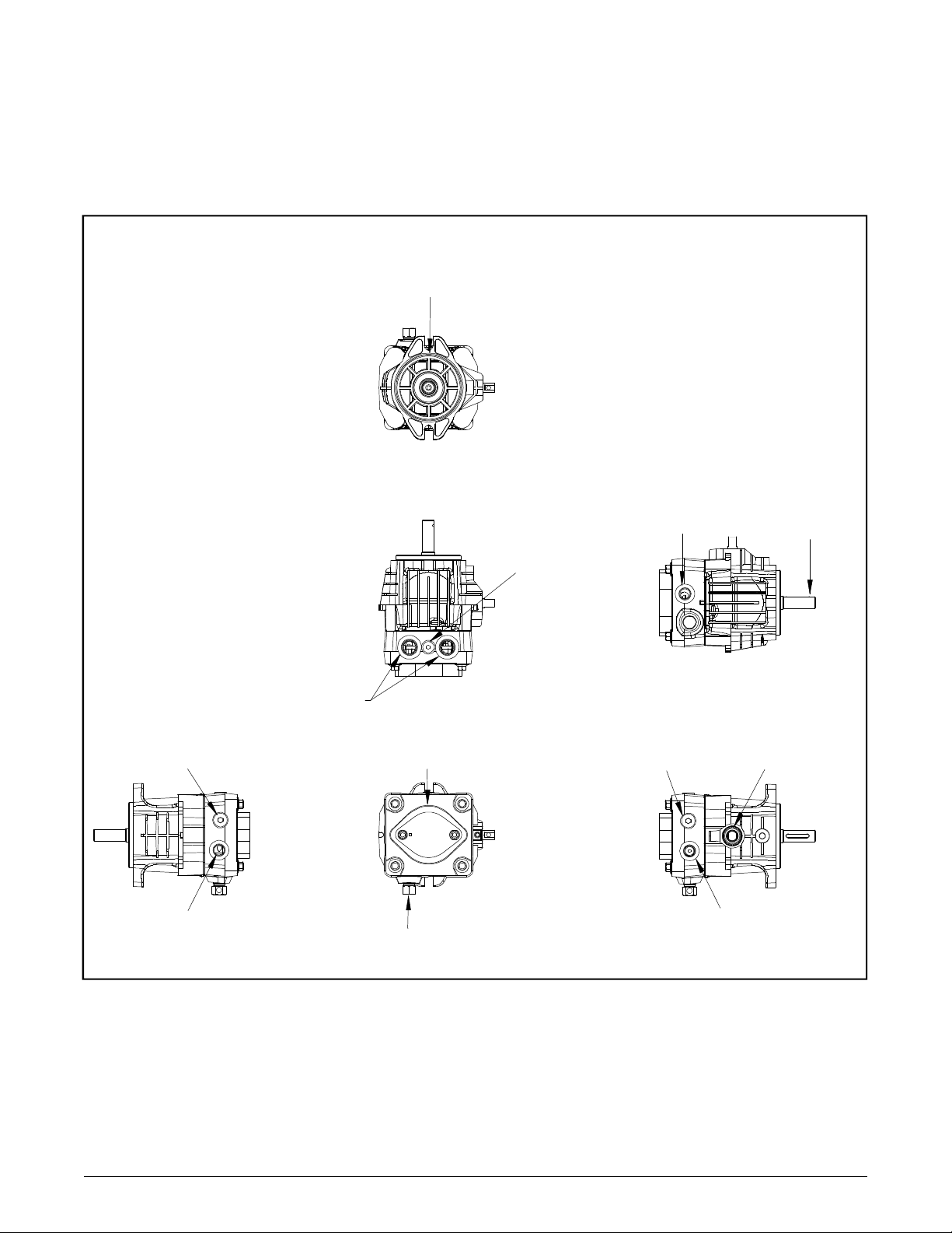
EXTERNAL FEATURES BDP-10A
SAE "A" PAD
FLANGE STYLE
STANDARD CHECK
VALVE OR SCR
CASE DRAIN
OPTION
"A" and "B"
PORTS
CHARGE
COVER
BYPASS VALVE
DIAGNOSTIC
PORT
INLET
STANDARD CHECK
VALVE OR SCR TRUNNION ARM
CASE DRAIN
OPTION
INPUT SHAFT
Figure 1. BDP-10A With Standard Charge Pump
2
www.mymowerparts.com
Page 3
For Husqvarna Parts Call 606-678-9623 or 606-561-4983
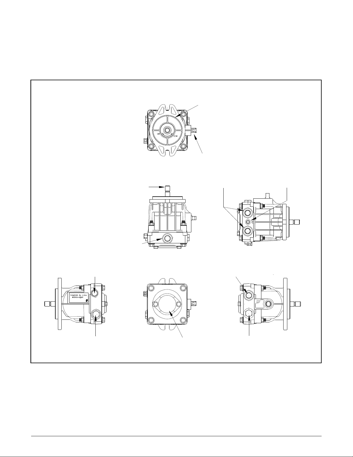
EXTERNAL FEATURES BDP-21L
SAE "B" PAD
FLANGE STYLE
TRUNNION ARM
INPUT SHAFT
INLET
BYPASS VALVE
STANDARD CHECK
VALVE OR SCR
CHARGE
COVER
"A" and "B"
PORTS
CASE DRAIN
STANDARD CHECK
VALVE OR SCR
DIAGNOSTIC
PORT
3
Figure 2. BDP-21L With Standard Charge Pump
BDP-10A/21L
www.mymowerparts.com
Page 4
BDP-10A/21L
For Husqvarna Parts Call 606-678-9623 or 606-561-4983
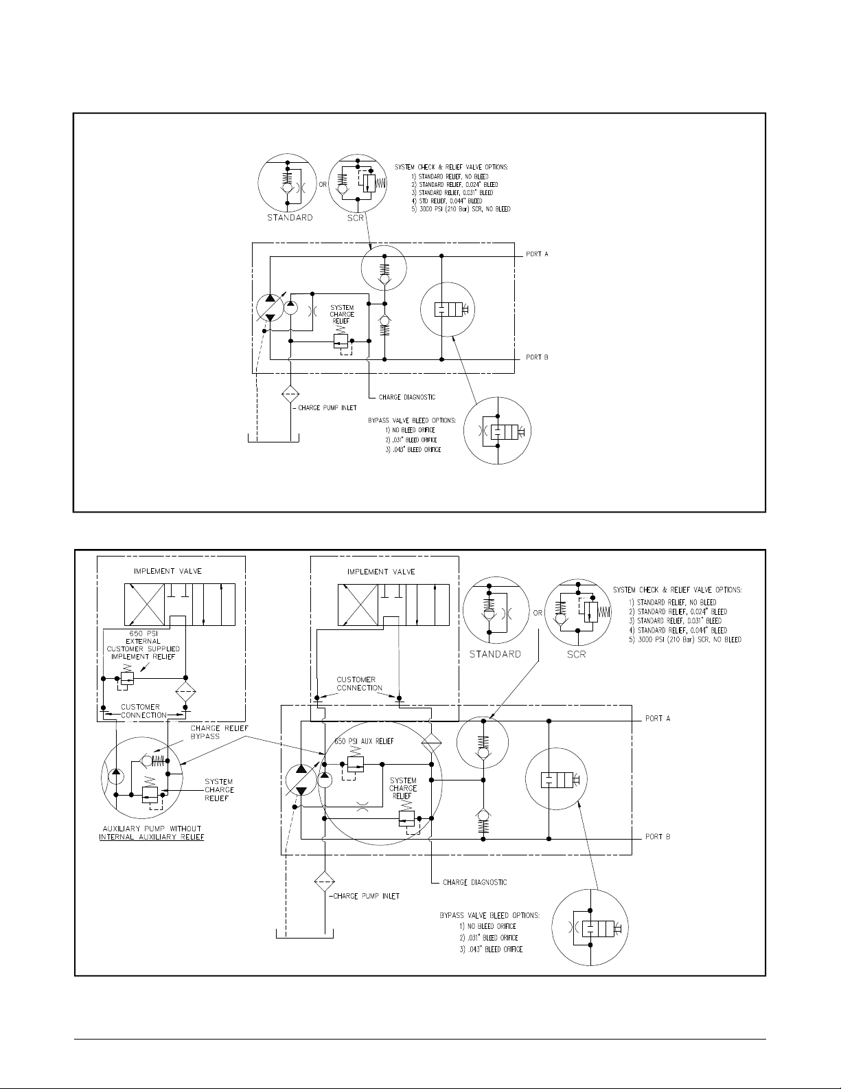
HYDRAULIC SCHEMATIC
Figure 3. BDP-10A/21L Standard With Charge Pump Hydraulic Schematic
Figure 4. BDP-10A/21L With Auxiliary Charge Pump Hydraulic Schematic
4
www.mymowerparts.com
Page 5
For Husqvarna Parts Call 606-678-9623 or 606-561-4983
GRAPHICAL SCHEMATIC
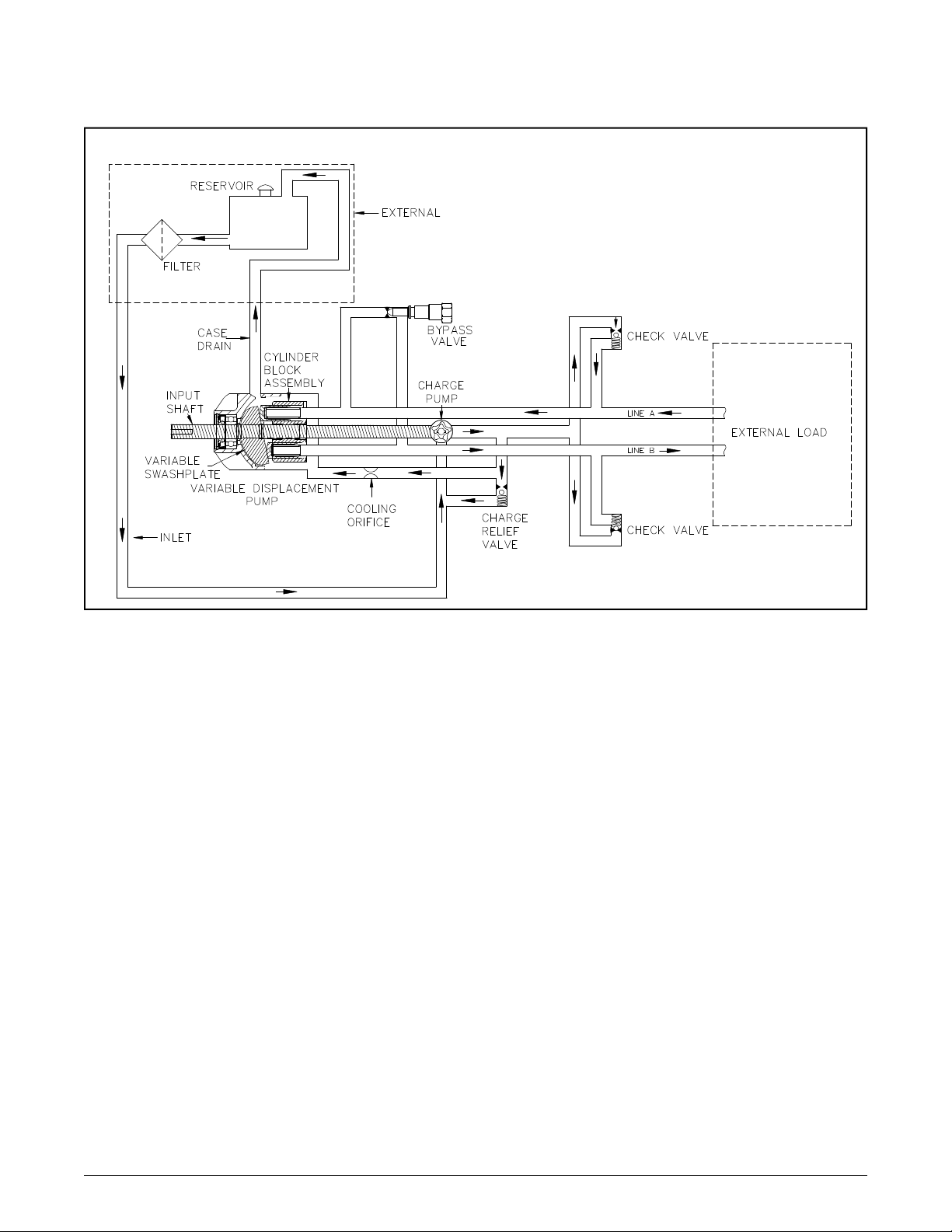
Figure 5. BDP-10A/21L Standard Charge Pump Graphical Schematic
Figures 3. and 4. represent hydraulic schematics of the standard charge and auxiliary charge
pump. Figure 5. provides a graphical illustration of the hydraulic oil circuit.
The input shaft and pump cylinder block are turned
in one direction only by the engine/ drive belt/
pulley combination or direct drive gear box.
The oil is drawn through an external filter that prevents contaminants within the reservoir from entering into the charge pump gerotor.
The charge pump supplies fluid to keep the
closed loop pressurized, preventing cavitation
and providing cooling oil flow for the system.
The charge relief valve is used to maintain charge
at a predetermined pressure.
Output of the system oil flow is controlled by the
direction and amount that the swashplate is
angled. As the pump pistons compress, they
force oil into one of two passageways (“A” or “B”)
in the system hydraulic circuit. Oil is supplied ex-
ternally under pressure to an external load, (e.g.,
a vehicle wheel motor). As the angle of the pump
swashplate is increased, the amount of oil being
pumped will increase and cause a higher speed
output of the wheel motor. Reversing the angle
of the swashplate will reverse the direction of the
oil flow. During the operation of the pump, fluid
is “lost” from the hydraulic loop through leak paths
designed into the product for lubrication purposes
(around pistons, under the rotating cylinder
block, etc.). This “lost” fluid returns to the reservoir through the case drain. This fluid must be
made up in the loop. The charge pump makes
up this fluid loss.
The makeup flow is controlled (or directed) by
the system check valves. The check valves are
used to direct makeup fluid into the low pressure
side of the closed loop. Each check valve will
either be held open or closed, depending upon
the direction of the vehicle operation: Closed in
a pressurized system passage, open in a low
pressure, “charged” system passage.
5
BDP-10A/21L
www.mymowerparts.com
Page 6
BDP-10A/21L
For Husqvarna Parts Call 606-678-9623 or 606-561-4983
TECHNICAL SPECIFICATIONS
BDP-10A
Displacement: 0.623 in3 / rev (10.2 cc / rev)
8.09 gpm@3000 rpm
Input Speeds
Maximum: 3600 rpm
Minimum: 1800 rpm
System Operating Pressure
Intermittent: 2100 psi (145 bar)
Continuous: 1000 psi (70 bar)
Oil Temperature
Maximum Intermittent: 230°F (110°C)
Normal Operating Range: -10° to 200°F
(-23°C to 93°C)
Fluid Viscosity Limits
@ 212°F (100°C) Optimum: 70 SUS (13 cSt)
@ 212°F (100°C) Minimum: 55 SUS(9.0 cSt)
Weight
8 lbs / 3.6 kg
Table 1. BDP-10A/21L Technical Specifications
BDP-21L
Displacement: 1.33 in3 / rev, (21.8 cc / rev)
17.3 gpm@3000 rpm
Input Speeds
Maximum: 3600 rpm
Minimum: 1800 rpm
System Operating Pressure
Intermittent: 2500 psi (172 bar)
Continuous: 1250 psi (86 bar)
Oil Temperature
Maximum Intermittent: 230°F (110°C)
Normal Operating Range: -10° to 200°F
(-23°C to 93°C)
Fluid Viscosity Limits
@ 212°F (100°C) Optimum: 70 SUS (13 cSt)
@ 212°F (100°C) Minimum: 55 SUS (9.0 cSt)
Weight
14 lbs / 6.3 kg
PRODUCT IDENTIFICATION
The label in Figure 6. can be located on the pump housing. It identifies the model and configuration of the BDP.
H Y D R O - G E A R
SULLIVAN, IL. U.S.A.
OEM Model/
Hydro-Gear
Number
I I III III IIII II II
BDP-10A - 300 or (BDP - 21L - 102)
I II IIII IIII III III I II IIII
0
Year Built
Date
(Julian - day of year)
131 P1 476
(unique number for that model - for that day)
Made in U.S.A.
Serial Number
Type of Product and Build Information
Figure 6. BDP Configuration Label
6
www.mymowerparts.com
Page 7
For Husqvarna Parts Call 606-678-9623 or 606-561-4983
SECTION 2. SAFETY
This symbol points out important safety
instructions which, if not followed, could endanger the personal safety and/or property of yourself and others. Read and follow all instructions
in this manual before attempting maintenance
on your BDP’s. When you see this symbol -
HEED ITS WARNING.
WARNING
POTENTIAL FOR SERIOUS INJURY
Inattention to proper safety, operation, or
maintenance procedures could result in
personal injury, or damage to the equipment. Before servicing or repairing the
BDP-10A/21L, fully read and understand
the safety precautions described in this
section.
Wear appropriate clothing. Loose or hanging
clothing or jewelry can be hazardous. Use the
appropriate safety equipment, such as eye and
hearing protection, and safety-toe and slip-proof
shoes.
Never use compressed air to clean debris from
yourself or your clothing.
TOOL SAFETY
Use the proper tools and equipment for the task.
Inspect each tool before use and replace any tool
that may be damaged or defective.
WORK AREA SAFETY
Keep the work area neat and orderly. Be sure it
is well lit, that extra tools are put away, trash and
refuse are in the proper containers, and dirt or
debris have been removed from the working areas of the machine.
PERSONAL SAFETY
Certain safety precautions must be observed
while servicing or repairing the BDP-10A/21L.
This section addresses some of these precautions but must not be considered an all-inclusive
source on safety information. This section is to
be used in conjunction with all other safety material which may apply, such as:
Other manuals pertaining to this machine
Local and shop safety rules and codes
Governmental safety laws and regulations
Be sure that you know and understand the equipment and the hazards associated with it. Do not
place speed above safety.
Notify your supervisor whenever you feel there is
any hazard involving the equipment or the performance of your job.
Never allow untrained or unauthorized personnel to service or repair the equipment.
The floor should be clean and dry, and all extension cords or similar trip hazards should be removed.
SERVICING SAFETY
Certain procedures may require the vehicle to
be disabled in order to prevent possible injury
to the servicing technician and/or bystanders.
The loss of hydrostatic drive line power may result in the loss of hydrostatic braking capability.
Some cleaning solvents are flammable. Use only
approved cleaning materials: Do not use explosive or flammable liquids to clean the equipment.
To avoid possible fire, do not use cleaning solvents in an area where a source of ignition may
be present.
Discard used cleaning material in the appropriate containers.
7
BDP-10A/21L
www.mymowerparts.com
Page 8
BDP-10A/21L
For Husqvarna Parts Call 606-678-9623 or 606-561-4983
SECTION 3. TROUBLESHOOTING
W ARNING
Do not attempt any servicing or adjustments with the engine running.
Use extreme caution while inspecting the
drive belt assembly and all vehicle linkage!
In many cases problems with the BDP-10A/21L
are not related to a defective pump but are
caused by slipping drive belts, partially engaged
bypass valves, and loose or damaged control
linkages. Be sure to perform all operational
checks and adjustments outlined in Section 3.
before assuming the pump is malfunctioning.
Table 2. below provides a troubleshooting check
Follow all safety procedures outlined in
the vehicle owner’s manual!
Table 2. BDP 10A/21L Troubleshooting Checklist
list to help determine the cause of operational
problems.
Possible Cause Corrective Action
VEHICLE DOES NOT DRIVE/TRACK STRAIGHT
Vehicle tires improperly inflated Refer to vehicle manufacturer suggested pressure
Control linkage bent, loose or out of adjustment Repair, adjust or replace vehicle linkage
Bypass loose Tighten bypass per page 11
Inlet leak Check all externals to BDP inlet
UNIT IS NOISY
Excessive input speed Adjust input above 1800 rpm and below 3600 rpm
Oil level low or contaminated oil Fill to proper level or change oil
Excessive loading Reduce vehicle load
Air trapped in hydraulic system Purge hydraulic system per page 12
Bypass loose Tighten bypass per page 11
Inlet leak, line or filter partially blocked or damaged Check all externals to BDP inlet
UNIT HAS NO/ LOW POWER
Engine RPM low Adjust to correct setting
Control linkage bent, loose or out of adjustment Repair or replace vehicle linkage
Drive belt slipping or pulley damaged Repair or replace drive belt or pulley
Oil level low or contaminated oil Fill to proper level or change oil per page 11
Excessive loading Reduce vehicle load
Bypass loose Tighten bypass per page 11
Air trapped in hydraulic system Purge hydraulic system per page 12
Inlet leak Check all externals to BDP inlet
Inlet filter clogged Replace filter per page 12
Suspected internal damage Check per page 9
UNIT OPERATING HOT
Debris buildup Remove debris
Cooling fan or heat exchanger damaged Repair or replace cooling fan or heat exchanger
Oil level low or contaminated oil Fill to proper level or change oil per page 11
Excessive loading Reduce vehicle load
Air trapped in hydraulic system Purge hydraulic system per page 12
Inlet leak Check all externals to BDP inlet
BDP LEAKS OIL
Damaged seals or gaskets Remove debris, replace seals
Air trapped in hydraulic system Purge hydraulic system per page 12
8
www.mymowerparts.com
Page 9
For Husqvarna Parts Call 606-678-9623 or 606-561-4983
BDP FLOW TEST KIT INSTRUCTIONS BLN-51334 Mar. 2000
(This Instruction Sheet supersedes all previous flow testing instructions)
Description: BDP Flow Test Kit (Part Number 70511)
(Part Number 70511 Supersedes Part Number BB-76810)
Purpose: The design purpose of the BDP Flow Test Kit is to allow the dealer to isolate the BDP from the wheel
motor and determine if the BDP is faulty. The following information can be used to install and test the BDP by
simulating a wheel motor load.
WARNING
Certain procedures require the vehicle engine
to be operated and the vehicle to be raised off of
the ground. To prevent possible injury to the
servicing technician and/or bystanders, insure
the vehicle is properly secured.
Do not attempt any adjustments with the engine
running. Use extreme caution while working in
or around all vehicle linkage! High temperatures
can be generated. Follow all safety procedures
outlined in the vehicle owner’s manual!
WARNING
INSTALLATION AND TESTING PROCEDURES:
1. Disconnect the system hoses at the wheel motor, or system hoses from the BDP and connect the BDPFlow
Test Kit. (Special care should be taken to prevent contamination debris from entering pump or wheel motor
system ports).
Note: Using the Bi-Directional Flow Test Kit, determination of directional flow is not necessary. The flow meter
may be connected in either direction into the forward and reverse high pressure system lines.
CAUTION: Ensure all fittings and hoses are attached securely. This test is being completed on the
vehicle’s high pressure system lines. Failure to perform this properly could result in bodily injury.
TESTING PROCEDURES:
1. Raise the drive tires off the ground. Block the remaining tires on the ground to prevent accidental vehicle
movement.
2. Open the restriction valve all the way.
3. Make certain all external BDP directional control stops are removed or backed off on the vehicle linkage to
obtain full pump directional control arm travel.
4. Start the engine and engage the drive pulley if necessary.
5. Bring the engine to maximum operating speed.
(This should not exceed 3600 rpm input speed on the BDP 10A/10L)
(This should not exceed 2800 rpm input speed when testing the BDP 21L)
Engine speed adjustment may be necessary to obtain 2800 rpm.
CAUTION: Damage to the flow meter and/or re-calibration may result from testing the BDP 21L at
input speeds that exceed 2800 rpm.
6. With the directional control lever (on the vehicle) for the pump being tested, move the control arm in full
forward motion. (It may be necessary to lock the control arm into full forward position to prevent false
readings).
7. Operate without any load for approximately 30 seconds to 1 minute, this allows the system oil temperature to
rise.
9
BDP-10A/21L
www.mymowerparts.com
Page 10
BDP-10A/21L
For Husqvarna Parts Call 606-678-9623 or 606-561-4983
Note: Raising the system oil temperature will make a difference in the readings you receive. It has been
determined that to complete this test accurately, the oil temperature must be near system operating temperatures.
Suggested temperature range 160°- 210°F (71.1° - 98.9°C)
8. (On the BDP-10L), tighten the restriction valve until you read 300 psi (21 bar).
(On the BDP-21L), tighten the restriction valve until you read 500 psi (34 bar).
Record the flow reading from the Bi-Directional Flow Meter.
9. Increase the pressure to 1100 PSI (76 bar) for both models (BDP-10L & BDP -21L).
Record the flow reading from the Bi-Directional Flow Meter.
10. The acceptable gpm “flow droop” or (difference) is:
BDP-10A/10L 1.5 gpm (5.6 l/min)
BDP-21L 2.0 gpm (7.6 l/min)
If the difference exceeds these values the pump would not be acceptable.
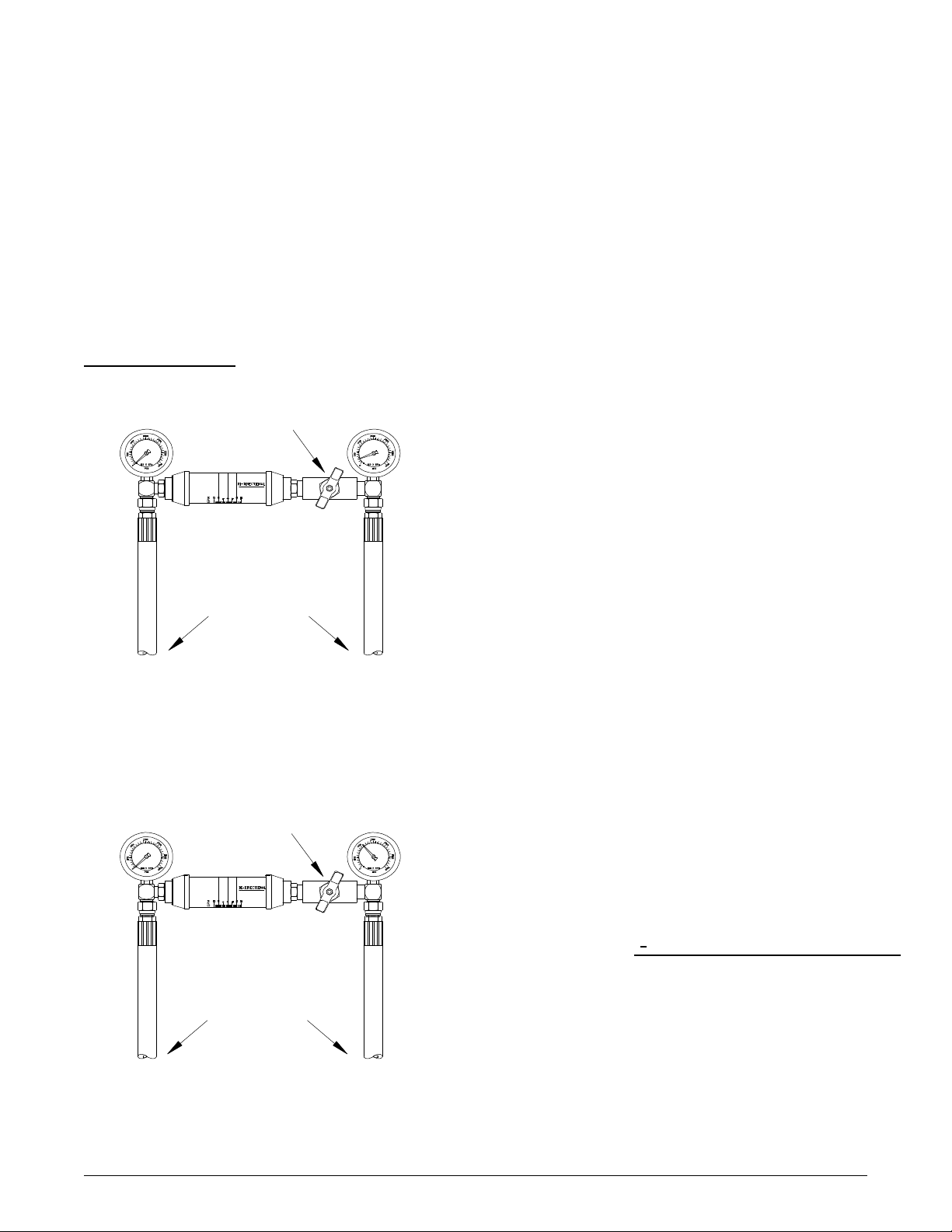
TEST EXAMPLE:
RESTRICTION
VALVE
BI-DIRECTIONAL
FLOWMETER
300 psi (21 bar) reading 5 gpm (19 l/min) (1st reading)
CONNECTIONS TO
THE FWD./RVS. LINES
DISCONNECTED
FROM WHEEL MOTOR
RESTRICTION
VALVE
BI-DIRECTIONAL
FLOWMETER
CONNECTIONS TO
THE FWD./RVS. LINES
DISCONNECTED
FROM WHEEL MOTOR
1100 psi (76 bar) reading 3 gpm (11 l/min) (2nd reading)
(BDP-10A/10L)
300 psi (21 bar) reading 5 gpm (19 l/min) (1st reading)
1100 psi (76 bar) reading 3 gpm (11 l/min) (2nd reading)
2 gpm (8 l/min) (the difference)
Subtract the 1st reading from the 2nd.
(In this example, 2 gpm difference would
indicate a defective pump).
10
www.mymowerparts.com
Page 11
For Husqvarna Parts Call 606-678-9623 or 606-561-4983
SECTION 4. SERVICE AND MAINTENANCE
NOTE: Any servicing dealer attempting
a warranty repair must have prior approval before conducting maintenance
of a Hydro-Gear product unless the servicing dealer is a current Authorized Hydro-Gear Service Center.
EXTERNAL MAINTENANCE
Regular external maintenance of the BDP should
include the following:
1. Check the vehicle operator’s manual for
the recommended load ratings. Insure
the current application does not exceed
load rating.
2. Check fluid level in reservoir in accordance
with vehicle manufacturer’s recommendations.
NOTE: After oil has been drained and
maintenance has been performed, clean
oil should be poured directly into the
pump inlet and high pressure ports prior
to plumbing reconnection and start-up.
3. Inspect the vehicle drive belt, idler pulley(s),
and idler spring(s). Insure that belt slippage
is not causing low input rpm to the pump.
4. Inspect all external plumbing for possible
leaks or loose fittings. An air leak may be
difficult to detect on the “suction side” or inlet
line to the pump. See purging procedures
page 12.
5. Insure correct inlet filter(s) has been installed
in accordance with the vehicle manufacturer.
6. Insure the reservoir is free of contaminants
and is properly vented.
7. Inspect the BDP cooling fan (if applicable)
for broken or distorted blades and remove
any obstructions (grass clippings, leaves or
dirt). Inspect oil cooler (if applicable) for damaged fins and debris.
8. Inspect the vehicle control linkage to the directional control arm on the BDP. Also, insure the control arm is securely fastened to
the trunnion arm.
9. Inspect the bypass on the BDP to insure it is
properly engaged for operation. If the bypass
is not fully engaged (rotated fully clockwise)
it will not function properly. For vehicle movement, the bypass may be backed out (2)
turns maximum. This is recommended for
movement of short distances at low speeds.
WARNING
Loosening the bypass will result in loss
of hydraulic braking capability.
SERVICE AND MAINTENANCE
PROCEDURES
NOTE: Damage to BDP’s may result from
external or internal contamination: Heat
from excess debris or lack of lubrication
and over-pressurization of the product.
Follow guidelines established in this
manual and the vehicle manufacturer’s
recommendations.
All the service procedures presented on the following pages can be performed while the BDP
is mounted on the vehicle. Any servicing beyond
those given must be performed after the unit has
been removed from the vehicle.
FLUIDS
The fluids used in Hydro-Gear products have
been carefully selected, and only equivalent, or
better products should be substituted.
Typically, an engine oil with a minimum rating of
55 SUS (9.0 cSt) at 210° F (98.9C) maximum
operating temperature and an API classification
of SH/ CD is allowed. Refer to the vehicle manufacturer for recommended oil.
11
BDP-10A/21L
www.mymowerparts.com
Page 12
BDP-10A/21L
For Husqvarna Parts Call 606-678-9623 or 606-561-4983
FLUID VOLUME AND LEVEL
Certain situations may require additional fluid to
be added or even replaced. Refer to the vehicle
manufacturer’s recommendations for the proper
fill location and level. After maintenance or oil
change, follow purging procedures below and recheck the fluid level once the unit has been operated for approximately 1 minute.
FLUID CHANGE
In the event of oil contamination or degradation,
oil addition or change may alleviate certain performance problems. Refer to the vehicle
manufacturer’s recommended oil change frequency. Refer to purging procedures below.
FILTERS
An inlet filter is required to insure that only clean
fluid enters the system. Refer to the vehicle manufacture for approved filter replacement.
PURGING PROCEDURES
Due to the effects air has on efficiency in hydrostatic drive applications, it is critical that air is
purged from the system.
These purge procedures should be implemented anytime a hydrostatic system has been
opened to facilitate maintenance or any additional oil has been added to the system.
Air creates inefficiency because it has compression and expansion rates that are higher than
that of oil.
Entrained air in the oil may cause the following
symptoms:
1. Noisy operation
2. Lack of power or drive after short-term operation
3. High operation temperature and excessive
expansion of oil.
Before starting, make sure the reservoir is at the
proper oil level. If it is not, fill to the vehicle
manufacturer’s specifications.
The following procedures should be performed
with the vehicle drive wheels off the ground, then
repeated under normal operating conditions.
WARNING
POTENTIAL FOR SERIOUS INJURY
Certain procedures require the vehicle
engine to be operated and the vehicle to
be raised off of the ground. To prevent
possible injury to the servicing technician and/or bystanders, insure the vehicle is properly secured.
1. With the bypass valve open and the engine
running, slowly move the directional control
in both forward and reverse directions (5 to 6
times), as air is purged from the unit, the oil
level will drop.
2. With the bypass valve closed and the engine
running, slowly move the directional control
in both forward and reverse directions (5 to 6
times). Check the oil level, and add oil as required after stopping engine.
3. It may be necessary to repeat Steps 1 and 2
until all the air is completely purged from the
system. When the BDP’s move forward and
reverse at normal speed purging is complete.
Cleanliness is a key factor in the successful repair of BDP’s. Thoroughly clean all exposed
surfaces prior to any type of maintenance. Cleaning of all parts by using a solvent wash and air
drying is usually adequate. As with any precision equipment, all parts must be kept free of
foreign material and chemicals. Protect all exposed sealing areas and open cavities from damage and foreign material.
Upon removal, all seals, O-rings, and gaskets
should be replaced. During installation, lightly
lubricate all seals, O-rings, gaskets with clean
petroleum jelly prior to assembly. Also protect
the inner diameter of seals by covering the shaft
machined features with plastic wrap or equivalent.
12
www.mymowerparts.com
Page 13

For Husqvarna Parts Call 606-678-9623 or 606-561-4983
SECTION 5. REPAIR
HOW TO USE THIS MANUAL
Each assembly is provided with an exploded view showing the parts involved. The complete exploded views and items lists are provided at the end of the repair section in this manual.
All figures show item references for assembly instructions only. See pages 31, 32, 33 and
34 for item and kit availability.
TOOLS AND TORQUES
Table 3. Required Tools
Miscellaneous
BDP-10A/21L Service & Repair Manual
Torque Wrench
Scribe, Paint Pen, or Marker
Seal Hook with a Magnet
Flat Blade Screw Driver
Pliers
Internal Snap Ring
Allen Wrenches
5 mm
3/16”
1/4”
Table 4. BDP-10A Plug Fitting Torque Values
Item # or Description Torque
Case Drain (fitting torque) 200-250 lb-in (22.6-28.2 N-m)
System Port (fitting torque) 370-470 lb-in (41.8-53.1 N-m)
Inlet (fitting torque) 200-250 lb-in (22.6-28.2 N-m)
52, Check Valve 180-240 lb-in (20.3-27.1 N-m)
80, Check Relief Cap 200-275 lb-in (22.6-31.0 N-m)
15, Bypass Valve 84-120 lb-in (9.5-13.6 N-m)
56, Diagnostic Plug 84-120 lb-in (9.5-13.6 N-m)
10, Cap Screw (non-auxiliary) 87-118 lb-in (9.8-13.3 N-m)
4, End Cap Bolts 167-217 lb-in (18.8-24.5 N-m)
Sockets
3/8” Drive Ratchet
9/16”
1/2”
5/8”
10 mm
Combination Wrenches
9/16”
1/2”
5/8”
7/8”
10 mm
Table 5. BDP-21L Plug Fitting Torque Values
Item # or Description Torque
Case Drain fitting (fitting torque) 370-470 lb-in (41.8-53.1 N-m)
System Port (fitting torque) 370-470 lb-in (41.8-53.1 N-m)
Inlet (fitting torque) 370-470 lb-in (41.8-53.1 N-m)
42A, 42B, Check Valves 180-240 lb-in (20.3-27.1 N-m)
42A, 42B, Check Reliefs (cap) 200-275 lb-in (22.6-31.0 N-m)
50, Bypass Valve 84-120 lb-in (9.5-13.6 N-m)
52, Diagnostic Plug 84-120 lb-in (9.5-13.6 N-m)
56, Charge Cover Cap Screw(non-auxiliary) 200-275 lb-in (22.6-31.0 N-m)
58, End Cap Bolts 255-345 lb-in (28.8-38.9 N-m)
13
www.mymowerparts.com
BDP-10A/21L
Page 14
BDP-10A/21L
For Husqvarna Parts Call 606-678-9623 or 606-561-4983
Use only original Hydro-Gear replacement parts
found listed in BLN-50937 (microfiche).
Lip type seals (shaft seals) are used on the input
shaft and directional control shaft of the BDP10A/21L. These seals can be replaced without
major disassembly of the unit. However, replacement of these seals generally requires removal
of the pump from the machine.
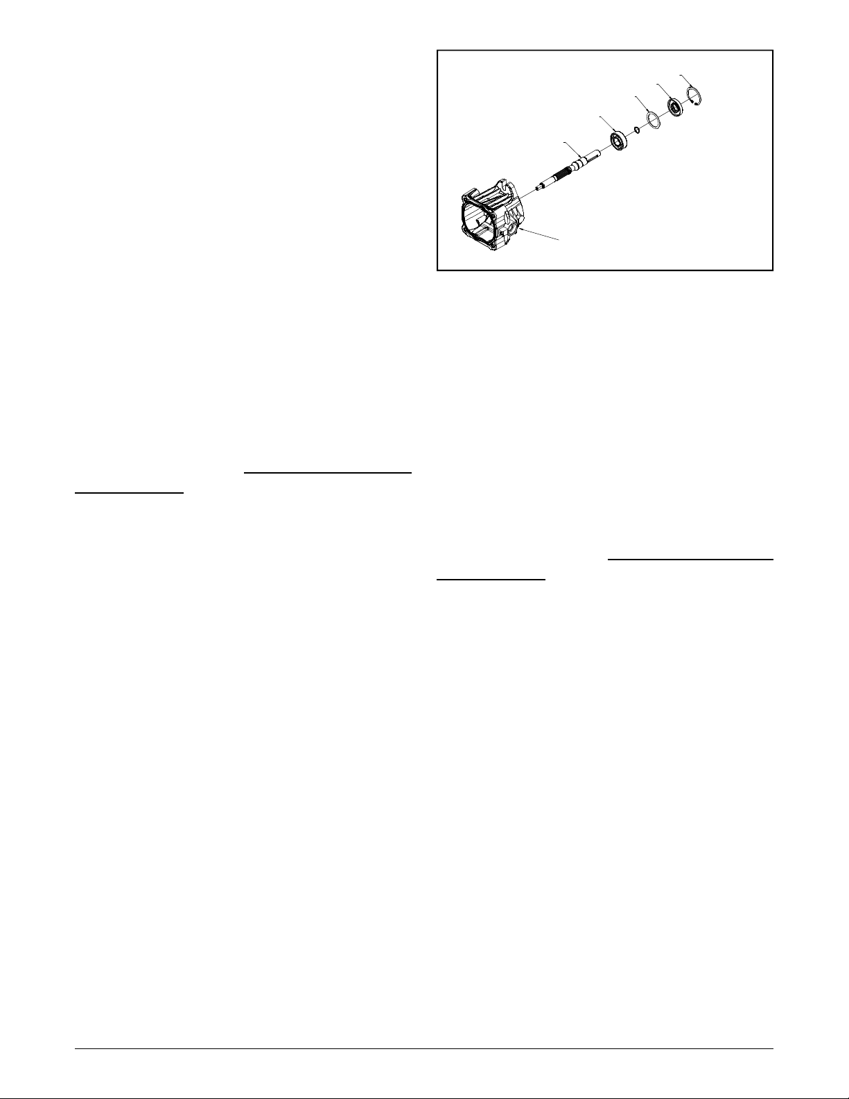
REMOVAL, INSPECTION AND/OR REPLACEMENT OF INPUT SHAFT
SEAL BDP-10A
Refer to Figure 7.
Disassembly BDP-10A
1. Remove retaining ring (22) from housing.
2. Remove lip seal (20). Care must be taken to
prevent damage to the housing bore, shaft sealing surface, or bearing. Once removed, the seal
is not reusable.
22
20
21
19
18
1
Figure 7 . BDP-10A
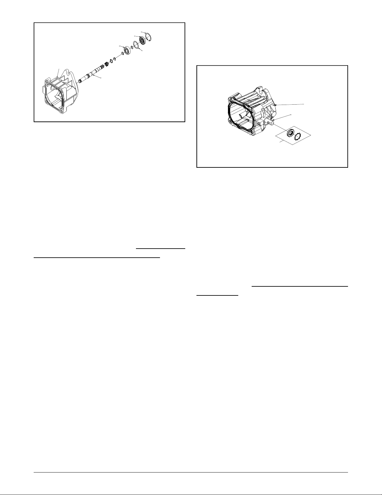
REMOVAL, INSPECTION AND/OR REPLACEMENT OF INPUT SHAFT
SEAL BDP-21L
Refer to Figure 8.
Disassembly BDP-21L
1. Remove retaining ring (3) from housing (15).
Inspection BDP-10A
1. With seal removed inspect the spacer (21),
input shaft bearing (19) and housing (1) bore for
damage, corrosion or wear.
Assembly BDP-10A
1. Lubricate the new lip seal (20) with petroleum
jelly.
2. Wrap the input shaft (18) with plastic wrap to
prevent damage to the inner surface of the lip
seal (20).
3. Slide seal (20) over shaft (18) so that lettering on the seal faces out.
4. Press the lip seal (20) into the housing bore.
Insure the lip seal (20), shaft (18) or housing (1)
bore does not become damaged.
5. Install the retaining ring (22) into the housing
(1) bore groove.
2. Remove lip seal (6). Care must be taken to
prevent damage to the housing bore, shaft, sealing surface, or bearing. Once removed the seal
is not reusable.
Inspection BDP-21L
1. With the lip seal (6) removed, inspect the
spacer (4) the shaft bearing (5) and housing (15)
bore.
Assembly BDP-21L
1. Lubricate the new lip seal (6) with petroleum
jelly.
2. Wrap the input shaft (1) with plastic wrap to
prevent damage to the inner surface of the lip
seal (6).
3. Slide the seal (6) over shaft (1) so that letter-
ing on the seal (6) faces out.
4. Press the lip seal (6) into the housing (15)
bore. Insure seal (6), shaft (1) or housing (15)
bore does not become damaged.
5. Install the retaining ring (3) into the housing
(15) bore groove.
14
www.mymowerparts.com
Page 15
For Husqvarna Parts Call 606-678-9623 or 606-561-4983
3
6
5
15
1
Figure 8 . BDP-21L
4
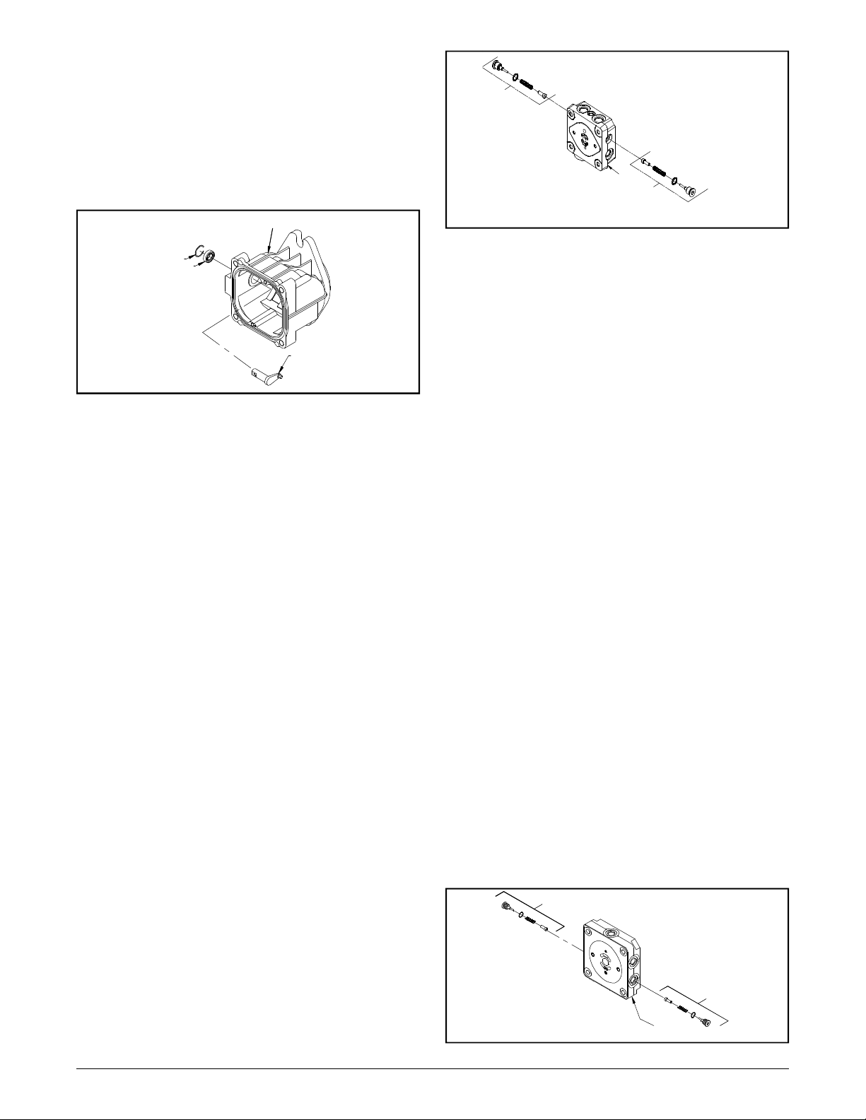
REMOVAL, INSPECTION AND/OR REPLACEMENT OF TRUNNION ARM
(CONTROL ARM) SEAL BDP-10A
Refer to figure 9.
Disassembly BDP-10A
1. Remove the retainer and lip seal (49) from
the housing (1). Care must be taken to prevent
damage to the housing trunnion bore, trunnion
arm (37) and sealing surface. Once removed
the retainer and lip seal is not reusable.
Inspection BDP-10A
1. With the lip seal (49) removed, inspect the
area for corrosion and wear. Inspect the trunnion bore area sealing surface for damage or
wear.
5. Install the retainer from (49) over the trunnion
arm (37) on top of the lip seal from (49). Press
into the trunnion seal bore in the housing until it
mates against the trunnion seal.
1
37
49
Figure 9 . BDP-10A
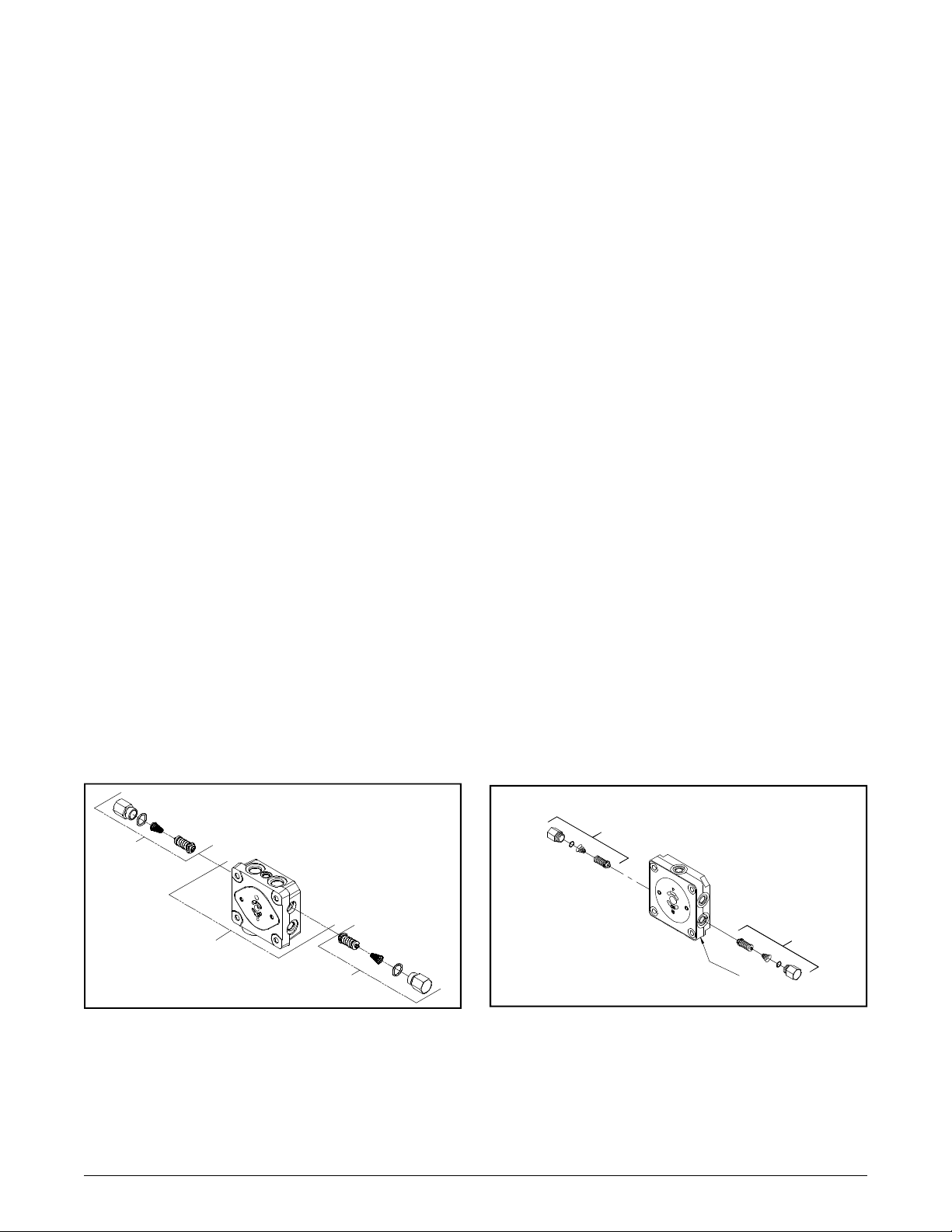
REMOVAL, INSPECTION AND/OR REPLACEMENT OF TRUNNION ARM
(CONTROL ARM) SEAL BDP-21L
Refer to figure 10.
Disassembly BDP-21L
1. Remove the retainer (10) and lip seal (2).
Care must be taken to prevent damage to the
housing trunnion bore, trunnion arm (13) and
sealing surface. Once removed lip seal (12) is
not reusable.
Inspection BDP-21L
Assembly BDP-10A
1. Lubricate the new lip seal (49) with petroleum
jelly.
2. Wrap the trunnion arm (37) with plastic wrap
to prevent damage to the inner surface of the lip
seal (49).
3. Slide the lip seal (49) over the trunnion arm
(37) so that the lettering on the seal (49) faces
out.
4. Press the lip seal (49) into the housing bore
(1). Insure the seal (49), trunnion arm (37), and
housing bore does not become damaged.
15
www.mymowerparts.com
1. With the lip seal (12) removed, inspect the
area for corrosion and wear. Inspect the trunnion bore area sealing surface for damage or
wear.
Assembly BDP-21L
1. Lubricate the new lip seal (12) with petroleum
jelly.
2. Wrap the trunnion arm (13) with plastic wrap
to prevent damage to the inner surface of the lip
seal (12).
3. Slide the lip seal (12) over the trunnion arm
(13) so that lettering on the seal (13) faces out.
BDP-10A/21L
Page 16
BDP-10A/21L
15
For Husqvarna Parts Call 606-678-9623 or 606-561-4983
4. Press the lip seal (12) into the housing bore
(15). Insure the seal (12), trunnion arm (13), and
housing bore does not become damaged.
5. Install the retainer (10) over the trunnion arm
(13) on top of the lip seal (12). Press into the
trunnion seal bore in the housing (15) bore ring
groove.
10
12
42A
(PORT "A"
SIDE)
2
42B
(PORT "B"
SIDE)
Figure 11 . BDP-10A
REMOVAL, INSPECTION AND/OR REPLACEMENT OF CHECK VALVES
BDP-21L
13
Figure 10 . BDP-21L
REMOVAL, INSPECTION AND/OR REPLACEMENT OF CHECK VALVES
BDP-10A
Refer to Figure 11.
Disassembly BDP-10A
Perform disassembly, inspection and assembly
on check valves one side at a time. Some units
vary in “A” side to “B” side check configuration.
1. Remove the check valve (42) with 1/4” allen
wrench.
2. Remove the valve spring and poppet from
the BDP end cap (2).
Refer to Figure 12.
Disassembly BDP-21L
Perform disassembly, inspection and assembly
on check valves one side at a time. Some units
vary in “A” side to “B” side check configuration.
1. Remove the check valve (42) with 1/4” allen
wrench.
2. Remove the valve spring and poppet from
the BDP end cap (25).
Inspection BDP-21L
1. Inspect the poppet and mating seats in the
end cap (25) for damage or foreign material.
Assembly BDP-21L
1. Lay the BDP on its side, so the check plug
port is horizontal.
Inspection BDP-10A
1. Inspect the poppets and mating seats in the
end cap (2) for damage or foreign material.
Assembly BDP-10A
1. Lay the BDP on its side, so the check plug
port is horizontal.
2. Insert the check plug, spring and poppet (42)
as one assembly into the check plug port.
Tighten, reference Table 4, page 13, for torque
values.
Repeat disassembly, inspection and assembly
for the opposite port side.
2. Insert the check plug, spring and poppet (42)
as one assembly into the check plug port.
Tighten, reference Table 5, page 13, for torque
values.
Repeat disassembly, inspection and assembly
for the opposite port side.
42B
42A
25
Figure 12 . BDP-21L
16
www.mymowerparts.com
Page 17
For Husqvarna Parts Call 606-678-9623 or 606-561-4983
REMOVAL, INSPECTION AND/OR REPLACEMENT OF SYSTEM CHECK
RELIEFS (SCR’s) BDP-10A
Refer to Figure 13.
Disassembly BDP-10A
Perform disassembly, inspection and assembly
on SCR one side at a time. Some units vary in
“A” side to “B” side check configuration.
1. Remove the system check relief (SCR) (42)
with a 7/8” wrench.
2. Remove the check relief spring and the check
relief from the BDP end cap (2).
Inspection BDP-10A
1. Inspect the check relief (42) and mating seat
in the end cap (2) for damage or foreign material.
REMOVAL, INSPECTION AND/OR REPLACEMENT OF SYSTEM CHECK
RELIEFS (SCR’s) BDP-21L
Refer to Figure 14.
Disassembly BDP-21L
Perform disassembly, inspection and assembly
on SCR one side at a time. Some units vary in
“A” side to “B” side check configuration.
1. Remove the system check relief (SCR) (42)
with a 7/8” wrench.
2. Remove the check relief spring and the check
relief from the BDP end cap (25).
Inspection BDP-21L
1. Inspect the check relief (42) and mating seats
in the end cap (25) for damage or foreign material.
Assembly BDP-10A
1. Lay the BDP on its side, so the check plug
port is horizontal.
2. Insert the system check relief spring and
check relief as one assembly into the check plug
port. Tighten, reference Table 4, page 13, for
torque values.
Repeat disassembly, inspection and assembly
for the opposite port side.
42A
(PORT "A"
SIDE)
2
42B
(PORT "B"
SIDE)
Assembly BDP-21L
1. Lay the BDP on its side, so the check plug
port is horizontal.
2. Insert the system check relief spring and
check relief (42) as one assembly into the check
plug port. Tighten, reference Table 5, page 13,
for torque values.
Repeat disassembly, inspection and assembly
for the opposite port side.
42B
42A
25
17
Figure 13 . BDP-10A
www.mymowerparts.com
Figure 14 . BDP-21L
BDP-10A/21L
Page 18
BDP-10A/21L
For Husqvarna Parts Call 606-678-9623 or 606-561-4983
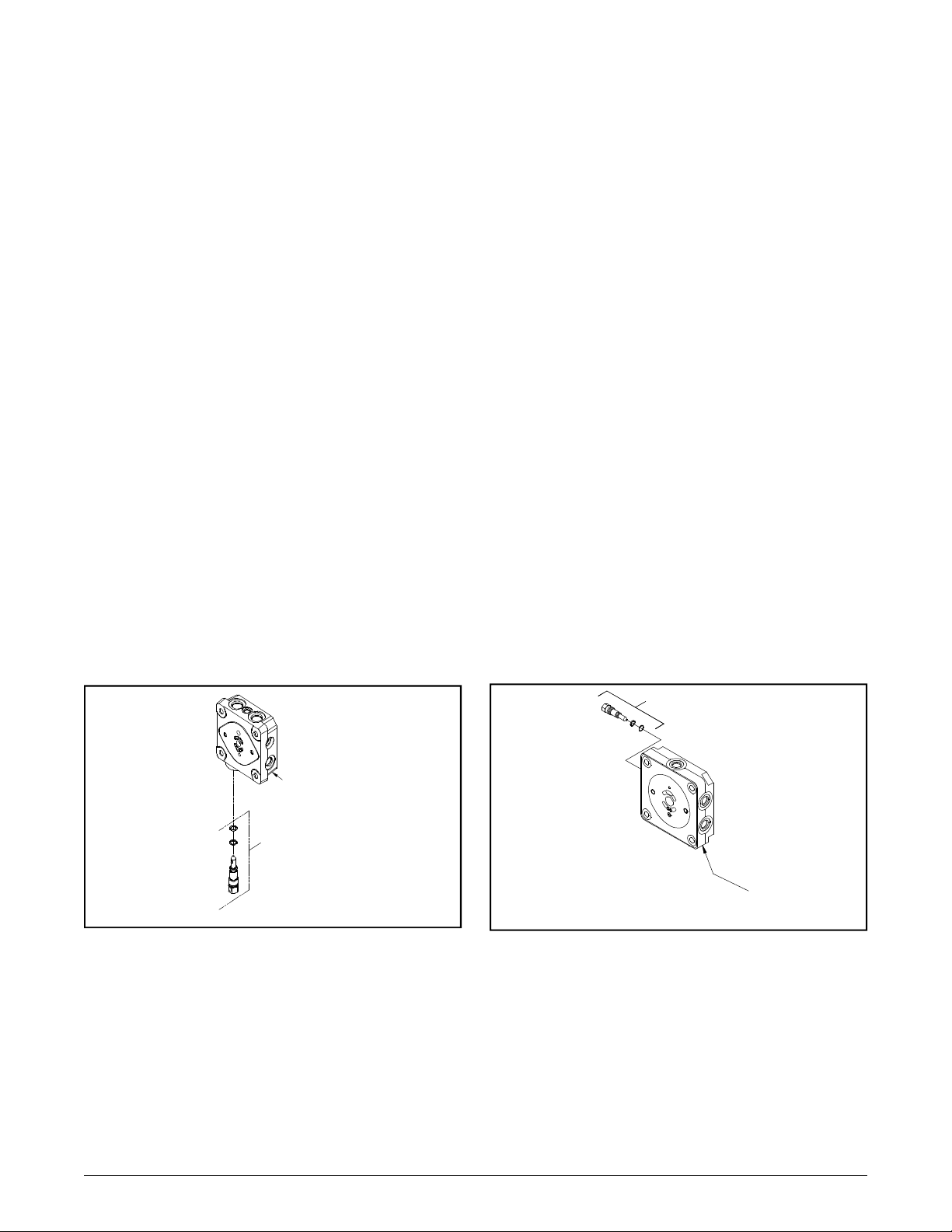
REMOVAL, INSPECTION AND/OR REPLACEMENT OF THE BYPASS BDP10A
Refer to Figure 15.
Disassembly BDP-10A
1. Loosen the bypass valve (15) using a 5/8”
wrench.
2. Remove the bypass (15) from the BDP end
cap (2).
Inspection BDP-10A
1. Inspect the bypass O-rings and mating seats
in the end cap (2) for damage or foreign material.
2. If damaged or worn replace bypass (15).
Assembly BDP-10A
1. Lay the BDP on its side, so the bypass port
is horizontal.
2. Insert the bypass (15) into the bypass port
on the end cap (2). Tighten, reference Table 4,
page 13, torque values.
REMOVAL, INSPECTION AND/OR REPLACEMENT OF THE BYPASS BDP21L
Refer to Figure 16.
Disassembly BDP-21L
1. Loosen the bypass valve (50) using a 5/8”
wrench.
2. Remove the bypass (50) from the BDP end
cap (25).
Inspection BDP-21L
1. Inspect the bypass O-rings and mating seats
in the end cap (25) for damage or foreign material.
2. If damaged or worn replace bypass (50).
Assembly BDP-21L
1. Lay the BDP on its side, so the bypass port
is horizontal.
2. Insert the bypass (50) into the bypass port
on the end cap (25). Tighten, reference Table 5,
page 13, torque values.
2
15
Figure 15 . BDP-10A
50
25
Figure 16 . BDP-21L
18
www.mymowerparts.com
Page 19
For Husqvarna Parts Call 606-678-9623 or 606-561-4983
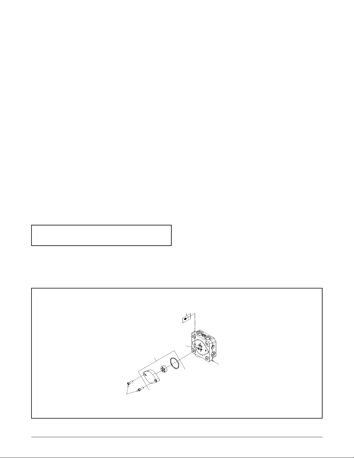
REMOVAL, INSPECTION OF THE
STANDARD CHARGE PUMP BDP10A
Refer to Figure 17.
Disassembly BDP-10A
1. Prior to removal of the charge cover, place a
mark on the charge cover and end cap for realignment.
2. Using a 5 mm allen wrench, loosen the charge
cover bolts (10) from the BDP end cap (2). While
holding the charge cover in place, remove the
charge cover bolts (10).
3. Remove the charge cover, O-ring, gerotor
items (6), charge spring and charge ball (44).
Inspection BDP-10A
1. Inspect the charge cover O-ring and running
surfaces for damage. Inspect the spring , check
ball (44), and mating seat in the end cap (2) for
damage or foreign material.
Assembly BDP-10A
1. Lay the BDP (input shaft down), so the end
cap (2) is horizontal. Place the charge ball (44)
in the end cap (2) charge pocket so it mates to
the end cap (2) charge ball seat. Place the
charge spring, also identified as item (44), on
top of the charge ball.
2. Insert the inner gerotor over input shaft (18).
3. Align the outer gerotor to fit over the inner
gerotor.
4. Insert the O-ring into the charge cover.
5. Position the charge cover and O-ring with the
aligning mark on the end cap. Place the charge
cover and O-ring as one piece over the charge
spring and gerotor assembly. Insure the spring
fits into the charge cover spring retaining groove.
6. Align and insert the allen screws (6) into the
end cap (2). Tighten, reference Table 4, page
13, torque values.
Note: If end cap (2) is to be removed, delay charge components reassembly.
Partial View
6
10
44
18
2
19
Figure 17 . BDP-10A
BDP-10A/21L
www.mymowerparts.com
Page 20
BDP-10A/21L
58 x4
For Husqvarna Parts Call 606-678-9623 or 606-561-4983
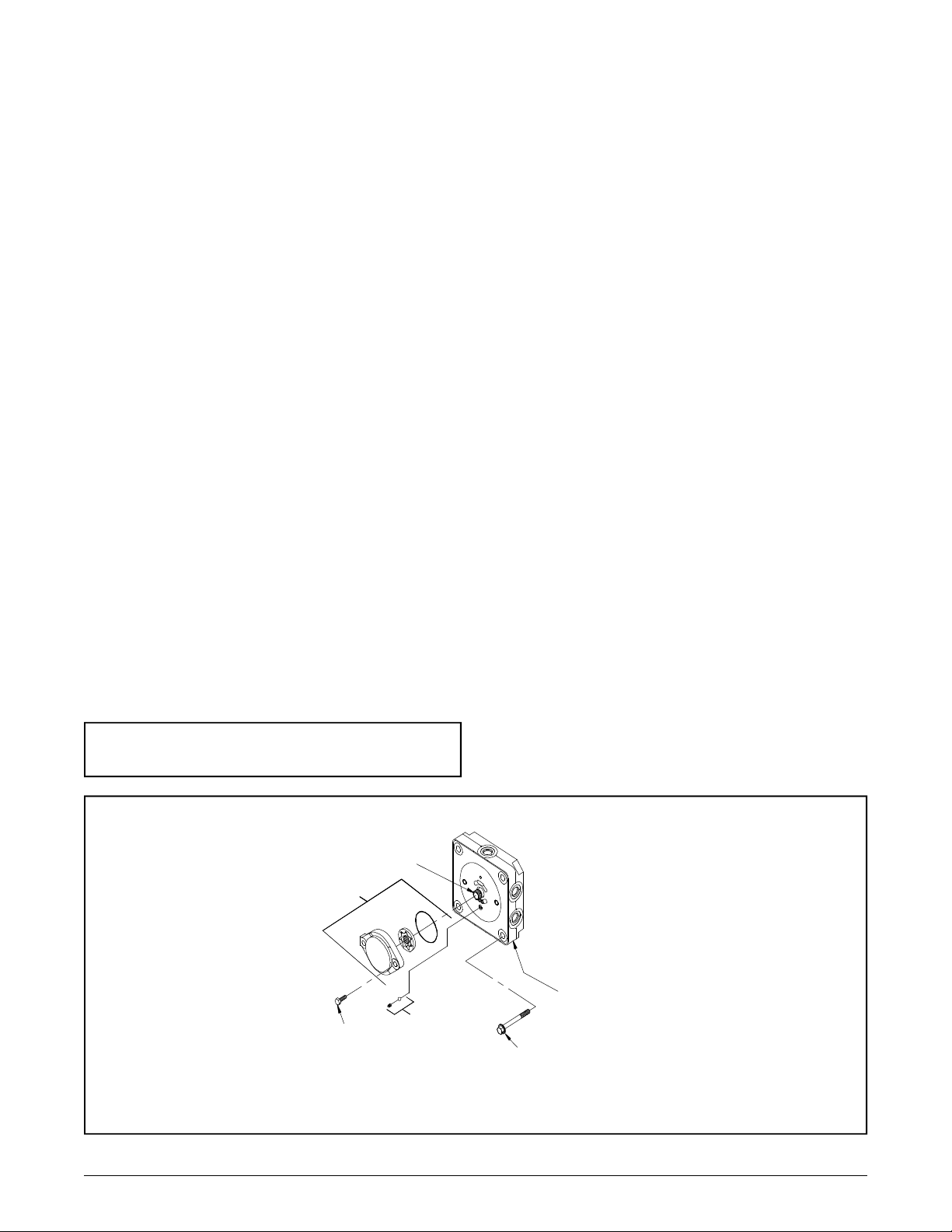
REMOVAL, INSPECTION AND ASSEMBLY OF THE STANDARD
CHARGE PUMP BDP-21L
Refer to Figure 18.
Disassembly BDP-21L
1. Prior to removal of the charge cover, place a
mark on the charge cover and end cap for realignment.
2. Using a 1/2” wrench loosen the charge cover
bolts from the BDP end cap (25). While holding
the charge cover in place, remove the charge
cover bolts (56).
3. Remove the charge cover, O-ring, gerotor
items (40), charge spring and charge ball (44).
Inspection BDP-21L
1. Inspect the charge cover O-ring and running
surfaces for damage. Inspect the spring , check
ball (44), and mating seat in the end cap (25) for
damage or foreign material.
2. If damaged or worn, replace O-ring and
gerotor assembly (40), charge spring and charge
ball (44) and end cap (25).
Assembly BDP-21L
1. Lay the BDP (input shaft down), so the end
cap is horizontal. Place the charge ball in the
end cap (25) charge pocket so it mates to the
end cap (25) charge ball seat. Place the charge
spring on top of the charge ball.
2. Insert the inner gerotor over input shaft (1).
3. Align the outer gerotor to fit over the inner
gerotor.
4. Insert the O-ring into the charge cover.
5. Position the charge cover and O-ring with the
aligning mark on the end cap (25). Place the
charge cover and O-ring as one piece over the
charge spring and gerotor assembly. Insure the
spring fits into the charge cover spring retaining
groove.
6. Align and insert the cap screws (58) into the
end cap. Tighten, per Table 5, page 13, torque
values.While holding the charge cover in place,
remove the charge cover bolts (56).
3. Remove the charge cover, O-ring, gerotor
items (40), charge spring and charge ball (44).
Note: If end cap (25) is to be removed,
delay charge components reassembly.
Partial View
40
56 x2
1
44
Figure 18 . BDP-21L
25
20
www.mymowerparts.com
Page 21
For Husqvarna Parts Call 606-678-9623 or 606-561-4983
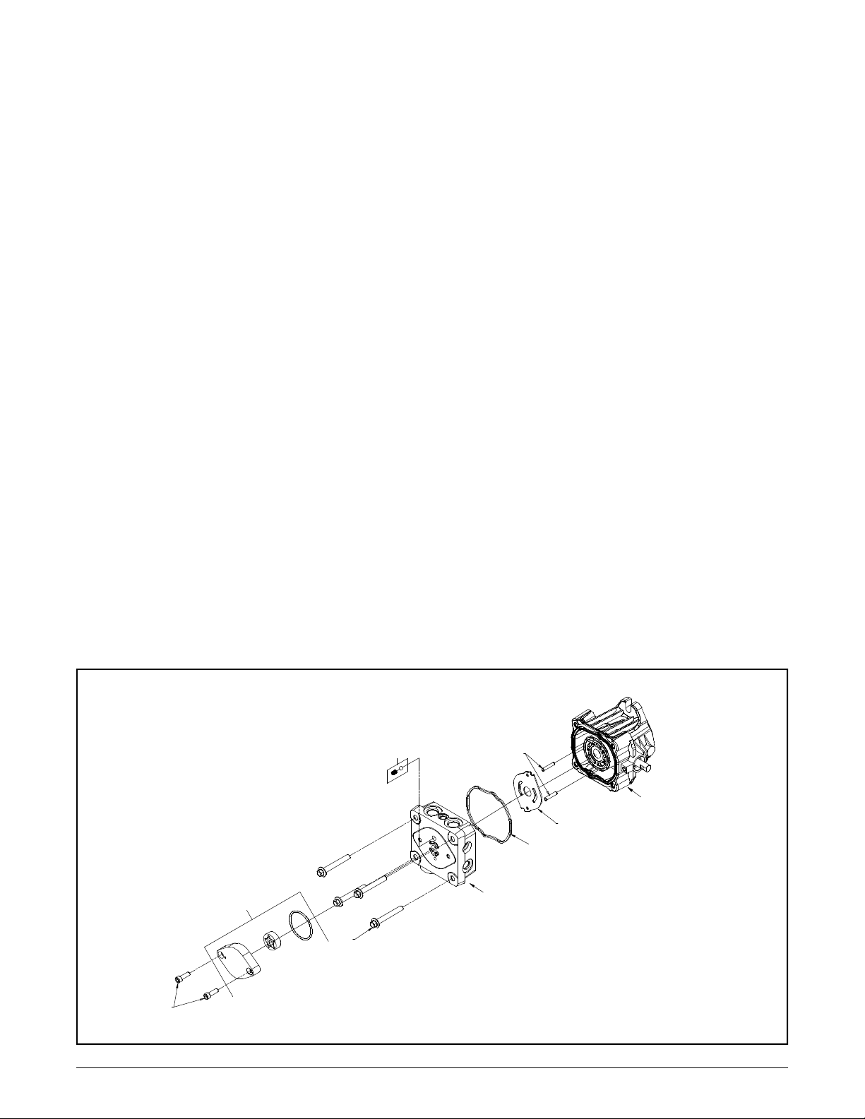
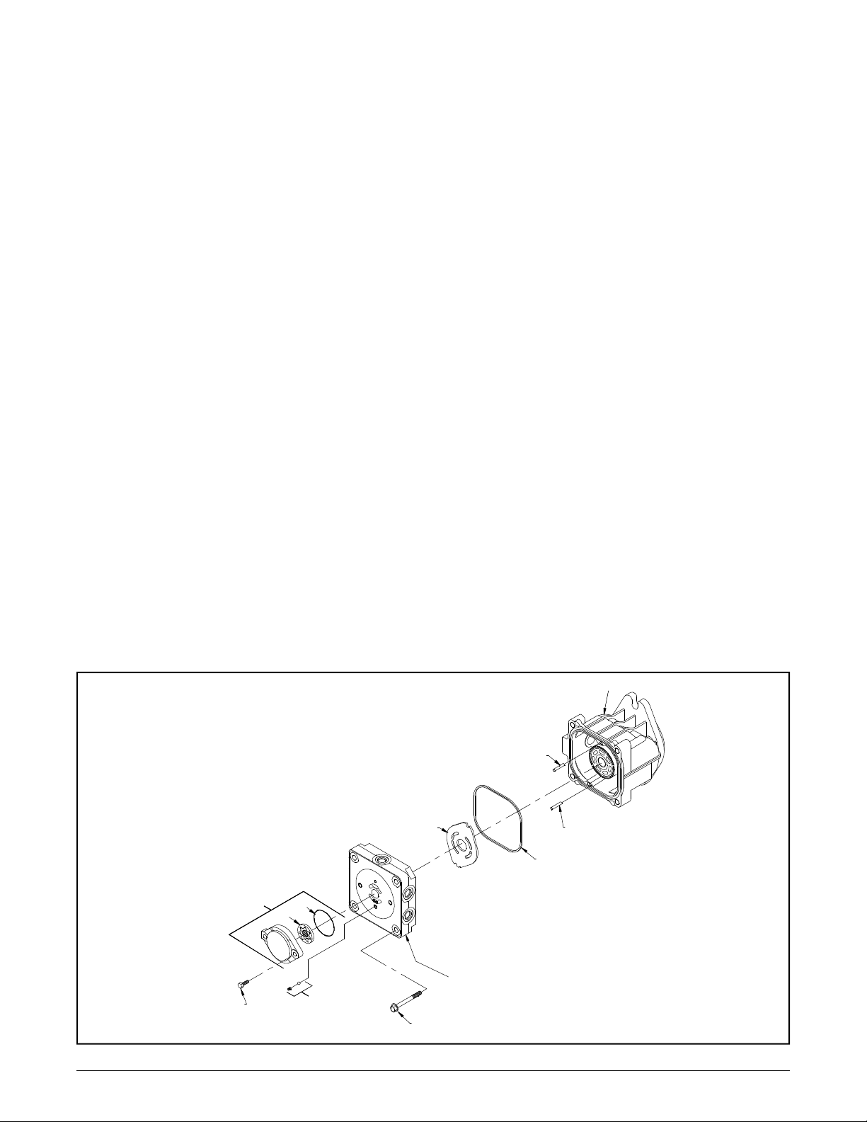
REMOVAL, INSPECTION AND ASSEMBLY OF THE END CAP AND
VALVE PLATE BDP-10A
Refer to Figure 19.
Disassembly BDP-10A
1. Using a 10 mm wrench, loosen the end cap
bolts (4) evenly.
2. Keeping the end cap (2) held in place, remove the four end cap bolts (4).
3. Slowly remove the end cap (2).
4. Remove the valve plate (31).
5. Remove housing alignment pins (3).
6. Remove housing gasket (5).
Inspection BDP-10A
1. Inspect the end cap (2) body for damage,
nicks or unusual wear patterns. Replace if necessary.
This is normal. Grooving in the plate, or material
transfer that is evident when the surface is
checked by dragging a fingernail across it, would
be cause for replacement of the valve plate.
3. Inspect and replace alignment pins (3) if bent
or distorted.
4. Replace the housing gasket (5) with a new
gasket before reassembly.
Assembly BDP-10A
1. Install housing gasket (5) into housing gasket
seat in housing (1).
2. Install alignment pins (3) into housing (1).
3. Install valve plate (31) with bronze side down
on top of cylinder block.
4. Install end cap (2). Before installing the four
end cap bolts (4), push down on end cap (2)
verifying alignment and insuring that the cylinder
block pistons spring back and forth. Install end
cap bolts (4). Tighten, reference Table 4, page
13, torque values.
2. Inspect the bronze side of the valve plate
(31). The running surface may show evidence
of minor abrasive rings.
44
6
4
10
3
1
31
5
2
21
Figure 19 . BDP-10A
BDP-10A/21L
www.mymowerparts.com
Page 22
BDP-10A/21L
For Husqvarna Parts Call 606-678-9623 or 606-561-4983
REMOVAL, INSPECTION AND ASSEMBLY OF THE END CAP AND
VALVE PLATE BDP-21L
Refer to figure 20.
Disassembly BDP-21L
1. Using any combination of two, 9/16” wrenches
or 9/16” socket and rachet drive, loosen the end
cap bolts (58) evenly.
2. Keeping the end cap (25) held in place remove the four end cap bolts (58).
3. Slowly remove the end cap (25).
4. Remove the valve plate (29).
5. Remove housing alignment pins (26).
6. Remove housing gasket (28).
Inspection BDP-21L
1. Inspect the end cap (25) body for damage,
nicks or unusual wear patterns. Replace if necessary.
This is normal. Grooving in the plate, or material
transfer that is evident when the surface is
checked by dragging a fingernail across it, would
be cause for replacement of the valve plate.
3. Inspect and replace alignment pins (26) if bent
or distorted.
4. Replace the housing O-ring (28) with a new
O-ring before reassembly.
Assembly BDP-21L
1. Install housing O-ring (28) into housing O-ring
seat in housing (15).
2. Install alignment pins (26) into housing (15).
3. Install valve plate (29) with bronze side down
on top of cylinder block.
4. Install end cap (25). Before installing the four
end cap bolts (58), push down on end cap (25)
verifying alignment and insuring that the cylinder
block pistons spring back and fourth. Install end
cap bolts. Tighten, per Table 5, page 13, torque
values.
2. Inspect the bronze side of the valve plate
(29). The running surface may show evidence
of minor abrasive rings.
40
56 x2
39
41
44
29
58 x4
15
26
26
28
25
Figure 20 . BDP-21L
22
www.mymowerparts.com
Page 23
For Husqvarna Parts Call 606-678-9623 or 606-561-4983
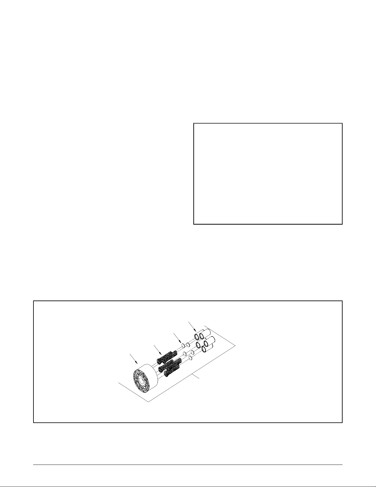
REMOVAL, INSPECTION AND ASSEMBLY OF THE CYLINDER BLOCK
BDP-10A
Refer to Figure 21.
Disassembly BDP-10A
1. Tilt the BDP on its side, drain remaining oil.
Lift out the cylinder block assembly (25).
2. Remove the pistons, springs and piston seats.
Inspection BDP-10A
1. Inspect the running surface of the cylinder
block and piston ends for damage, nicks or unusual wear patterns. The running surface may
show evidence of minor abrasion . This will be a
normal wear. If grooved or smeared, replace with
a new cylinder block assembly.
2. Inspect the piston springs for distortion or
breakage. If necessary, replace with new cylinder block kit.
Assembly BDP-10A
1. Install piston seats into the end of the pistons.
2. Install springs into the pistons.
3. Install one at a time, pistons, springs and seats
as one assembly into the cylinder block.
4. With the BDP housing tilted on its side, install
the cylinder block assembly (25) with pistons contacting the thrust bearing.
NOTE: To check that piston placement
is correct, push downward on the cylinder block assembly (25). If it results with
a spring action, the block has been assembled correctly without pistons slipping out. If this cannot be accomplished,
place a rubber band around the cylinder
block pistons to hold them in position
during installation. Then, after installation, cut the rubber band and remove it.
Check for piston spring action.
3. Inspect the piston seats. Residual oil may
cause these to remain stuck to the inside of the
pistons.
Piston
Piston
Seat
Spring
Cylinder
Block
25
23
Figure 21 . BDP-10A
BDP-10A/21L
www.mymowerparts.com
Page 24
BDP-10A/21L
For Husqvarna Parts Call 606-678-9623 or 606-561-4983
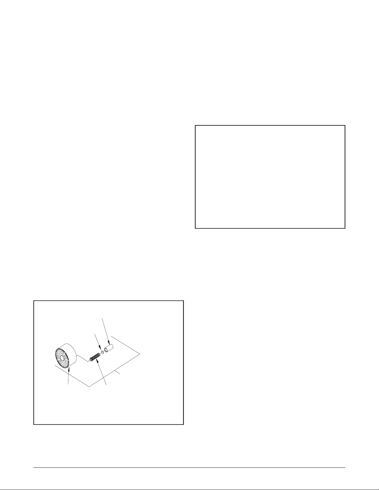
REMOVAL, INSPECTION AND ASSEMBLY OF THE CYLINDER BLOCK
BDP-21L
Refer to Figure 22.
Disassembly BDP-21L
1. Tilt the BDP on its side, drain remaining oil.
Lift out the cylinder block assembly (38).
2. Remove the pistons, springs and piston seats.
Inspection BDP-21L
1. Inspect the running surface of the cylinder
block and piston ends for damage, nicks or unusual wear patterns.
The running surface may show evidence of minor abrasion . This will be normal wear. If
grooved or smeared, replace with a new cylinder block assembly.
2. Inspect the piston springs for distortion or
breakage. If necessary, replace with new cylinder block kit.
Assembly BDP-21L
1. Install piston seats into the end of the pistons.
2. Install springs into the pistons.
3. Install one at a time, pistons, springs and seats
as one assembly into the cylinder block.
4. With the BDP housing tilted on its side, install
the cylinder block assembly (38) with pistons
contacting the thrust bearing.
NOTE: To check piston placement is correct, push downward on the cylinder
block assembly (38). If it results with a
spring action the block has been assembled correctly without pistons slipping out. If this cannot be accomplished,
place a rubber band around the cylinder
block pistons to hold them in position
during installation. Then after installation cut the rubber band and remove it.
Check for piston spring action.
3. Inspect the piston seats. Residual oil may
cause these to remain stuck to the inside of the
pistons.
Piston
Piston
Seat
38
Cylinder
Block
Figure 22 . BDP-21L
Spring
24
www.mymowerparts.com
Page 25
For Husqvarna Parts Call 606-678-9623 or 606-561-4983
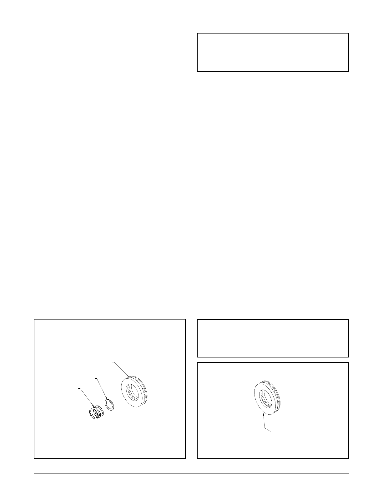
REMOVAL, INSPECTION AND ASSEMBLY OF BLOCKSPRING, THRUST
WASHER, AND THRUST BEARING,
BDP-10A
Refer to Figure 24.
Disassembly BDP-10A
1. Remove the block spring (29).
2. Remove the thrust washer (30).
3. Remove the thrust bearing and race (34).
Inspection BDP-10A
1. Inspect and replace the block spring (29) and
thrust washer (30) if they are distorted or broken.
2. Inspect the running surface of the bearing
race for damage, nicks or unusual wear patterns.
The running surface may show evidence of minor abrasion . This will be normal wear. Inspect
the bearings for free movement. Inspect the
bearing cage for distortion or damage. Replace
if necessary.
Assembly BDP-10A
NOTE: The difference in race thickness:
The thin race seats into the swashplate
(32). The thicker race will be installed
toward the piston noses.
2. Install thrust washer (30).
3. Install block spring (29).
REMOVAL, INSPECTION AND ASSEMBLY OF THRUST BEARING,
BDP-21L
Refer to Figure 25.
Disassembly BDP-21L
1. Remove the thrust bearing and race (17).
Inspection BDP-21L
1. Inspect the running surface of the bearing
race for damage (17), nicks or unusual wear patterns. The running surface may show evidence
of minor abrasion . This will be normal wear.
Inspect the bearings for free movement. Inspect
the bearing cage for distortion or damage. Replace if necessary.
1. Install thrust bearing and race assembly (34).
34
30
29
Figure 24 . BDP-10A
Assembly BDP-21L
1. Install bearing and race assembly (17).
NOTE: The difference in race thickness:
The thin race seats into the swashplate.
The thicker race will be installed toward
the piston noses.
17
Figure 25 . BDP-21L
25
BDP-10A/21L
www.mymowerparts.com
Page 26
BDP-10A/21L
For Husqvarna Parts Call 606-678-9623 or 606-561-4983
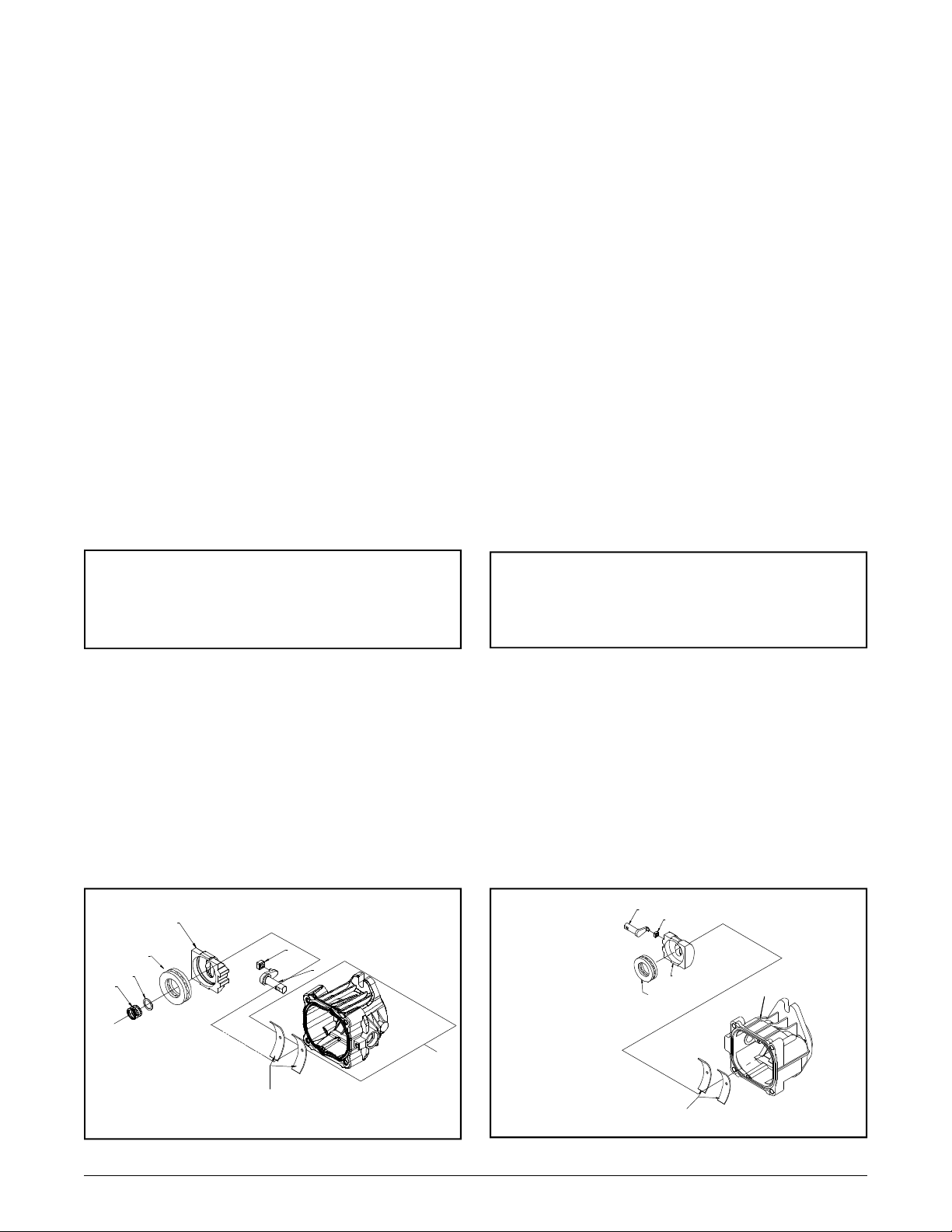
REMOVAL, INSPECTION OF
SWASHPLATE, INSPECTION OF
CRADLE BEARINGS BDP-10A
REMOVAL, INSPECTION AND ASSEMBLY OF SWASHPLATE, AND
CRADLE BEARINGS, BDP-21L
Refer to Figure 26.
Disassembly BDP-10A
1. Remove the swashplate(32).
Inspection BDP-10A
1. Inspect the running surface of the bearing
pocket for damage (32), nicks or unusual wear
patterns. The running surface may show evidence of minor abrasion . This will be normal
wear. Inspect the cradle bearing side of the
swashplate (32) for damage. Replace if necessary.
2. Inspect the cradle bearings attached to the
inside of housing (1) for normal wear patterns,
placement, and insure they are staked in place.
If damaged, replace housing (1).
NOTE: The cradle bearings will have discoloration due to normal wear. This, under normal circumstances, will not warrant replacement.
Refer to Figure 27.
Disassembly BDP-21L
1. Remove the swashplate (31).
Inspection BDP-21L
1. Inspect the running surface of the bearing
pocket for damage (31), nicks or unusual wear
patterns. The running surface may show evidence of minor abrasion . This will be normal
wear. Inspect the cradle bearing side of the
swashplate (31) damage. Replace if necessary.
2. Inspect the cradle bearings attached to the
inside of housing (15) for normal wear patterns,
placement, and insure they are staked in place.
If damaged, replace housing (15).
NOTE: The cradle bearings will have discoloration due to normal wear. This under normal circumstances will not warrant replacement.
Assembly BDP-10A
1. Install swashplate (13) by holding trunnion
arm’s (37) slot guide (38) with the aide of a flat
tip screwdriver. Use the screwdriver to hold the
slot guide (38) in place while positioning the
swash plate (32) onto the cradle bearing in the
housing (1).
2. Rotate trunnion arm (13) to assure swashplate
pivoting action.
32
34
30
29
(Cradle Bearings cannot be
removed from housing as depicted)
38
37
1
Assembly BDP-21L
1. Install swashplate (31) by holding trunnion
arm’s (13) slot guide (14) with the aide of a flat
tip screwdriver. Use the screwdriver to hold the
slot guide (14) in place while positioning the
swash plate (31) onto the cradle bearing in the
housing (15).
2. Rotate trunnion arm (13) to assure swashplate
pivoting action.
13
14
31
17
(Cradle Bearings cannot be
removed from housing as depicted)
15
Figure 26 . BDP-10A
www.mymowerparts.com
Figure 27 . BDP-21L
26
Page 27
For Husqvarna Parts Call 606-678-9623 or 606-561-4983
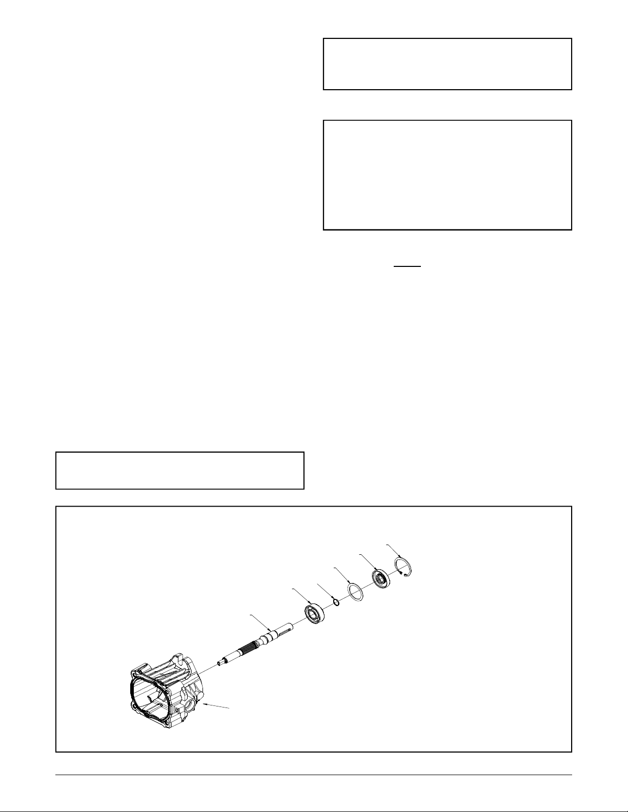
REMOVAL, INSPECTION AND ASSEMBLY OF INPUT SHAFT BDP10A
Refer to Figure 28.
Disassembly BDP-10A
1. Remove the retaining ring (22).
2. Remove the lip seal (20).
3. Remove the spacer (21).
4. Remove the shaft assembly (18) from the BDP.
Inspection BDP-10A
1. Inspect the input shaft (18) for worn splines,
surface damage, or keyway damage. Replace
shaft assembly if necessary.
2. Inspect the bearing (19) for evidence of scoring, corrosion, or damage. Replace shaft assembly if necessary.
3. Inspect and replace the spacer (21) if it is
bent or broken.
Note: If trunnion arm is to be removed,
delay reassembly of input shaft assembly.
Assembly BDP-10A
Note: Upon removal, it is recommended
that all seals, O-rings, and gaskets be
replaced. During installation, lightly lubricate all seals, O-rings and gaskets with
clean petroleum jelly prior to assembly.
Also, protect the inner diameter of seals
by covering the shaft with plastic wrap.
1. Install input shaft assembly (18) into the hous-
ing (1) bore. Light tapping with a rubber mallet
may be necessary on the input shaft (18) once
the bearing is aligned with the housing (1) bore. Rotate the input shaft (18) to insure free movement.
2. Install spacer (21).
3. Install new lip seal (20).
4. Install retaining ring (22).
4. Inspect and replace the retaining ring (22) if
it is bent or broken.
Note: Replace the input shaft seal (20)
after removal.
19
18
1
22
20
21
23
27
Figure 28 . BDP-10A
BDP-10A/21L
www.mymowerparts.com
Page 28
BDP-10A/21L
For Husqvarna Parts Call 606-678-9623 or 606-561-4983
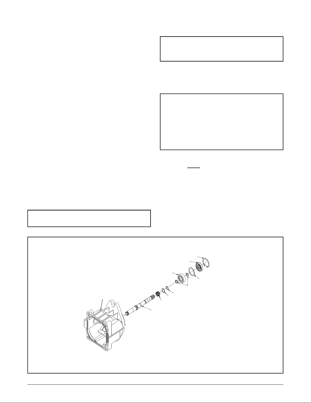
REMOVAL, INSPECTION AND ASSEMBLY OF INPUT SHAFT, BDP21L
Refer to Figure 29.
Disassembly BDP-21L
1. Remove the retaining ring (3).
2. Remove the lip seal (6).
3. Remove the spacer (4).
4. Remove the shaft assembly (1) from the BDP.
Inspection BDP-21L
1. Inspect the input shaft (1) for worn splines,
damage, or keyway damage. Replace shaft
assembly if necessary.
2. Inspect the bearing (5) for evidence of scoring, corrosion, or damage. Replace shaft assembly if necessary.
4. Inspect and replace the retaining ring (3) if it
is bent or broken.
Note: If trunnion arm is to be removed,
delay reassembly of input shaft assembly.
5. Inspect and replace the thrust spring (20) and
thrust washer (19) if they are distorted or broken.
Assembly BDP-21L
Note: Upon removal, it is recommended
that all seals, O-rings, and gaskets be
replaced. During installation, lightly lubricate all seals, O-rings and gaskets with
clean petroleum jelly prior to assembly.
Also, protect the inner diameter of seals
by covering the shaft with plastic wrap.
1. Install the shaft (1) assembly, into the housing
(15) bore.
Light tapping with a rubber mallet may
be necessary on the input shaft (1) once the bearing is aligned with the housing bore (15). Rotate
the input shaft (1) to insure free movement.
3. Inspect and replace the spacer (4) if it is bent
or broken.
Note: Replace the input shaft seal (6) after removal.
15
2. Install spacer (4).
3. Install new lip seal (6).
4. Install retaining ring (3).
3
6
5
4
2
2
19
20
1
Figure 29 . BDP-21L
28
www.mymowerparts.com
Page 29
REMOVAL, INSPECTION TRUNNION
REMOVAL, INSPECTION TRUNNION
For Husqvarna Parts Call 606-678-9623 or 606-561-4983
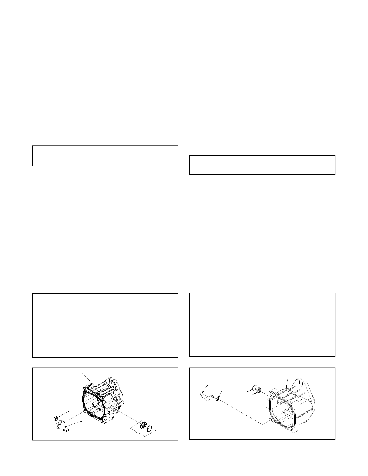
ARM BDP-10A
Refer to Figure 30.
Disassembly BDP-10A
1. Remove trunnion seal retainer and seal (49).
2. Remove slot guide (38).
3. Remove trunnion arm (37).
Inspection BDP-10A
1. Inspect the trunnion arm (37) for wear or damage. Replace trunnion if necessary.
Note: Replace the trunnion shaft seal
and retainer (49) after removal.
Assembly BDP-10A
1. Install the trunnion arm (37) into the housing
(1) bore. Rotate the trunnion arm to insure free
movement.
2. Install new seal and retainer from seal kit.
3. Refer to Figure 33, page 33. Install input shaft
(18), bearing (19), swashplate (32), bearing race
assembly. (34), cylinder block assembly (25),
end cap (2), valve plate and charge cover (4).
Tighten fasteners, reference Table 4, page 13,
for torque values.
Note: Upon removal, it is recommended
that all seals, O-rings, and gaskets be replaced. During installation, lightly lubricate all seals, O-rings and gaskets with
clean petroleum jelly prior to assembly.
Also protect the inner diameter of seals
by covering the shaft with plastic wrap.
ARM BDP-21L
Refer to Figure 31.
Disassembly -BDP-21L
1. Remove trunnion seal retainer (10) and seal
(12).
2. Remove slot guide (14).
3. Remove trunnion arm (13).
Inspection- BDP-21L
1. Inspect the trunnion arm (13) for wear or damage. Replace trunnion if necessary.
Note: Replace the trunnion shaft seal (12)
after removal.
Assembly - BDP-21L
1. Install the trunnion arm (13) into the housing
(15) bore. Rotate the trunnion arm to insure free
movement.
2. Install new seal and retainer from seal kit.
3. Refer to Figure 32, page 31. Install input
shaft (1), swashplate (31), bearing race assembly (17), cylinder block assembly (38), end cap
(25), valve plate and charge cover (40). Tighten
fasteners, reference Table 5, page 13, for torque
values.
Note: Upon removal, it is recommended
that all seals, O-rings, and gaskets be replaced. During installation, lightly lubricate all seals, O-rings and gaskets with
clean petroleum jelly prior to assembly.
Also, protect the inner diameter of seals
by covering the shaft with plastic wrap.
1
38
37
49
Figure 30 . BDP-10A
29
www.mymowerparts.com
16
13
14
10
12
Figure 31 . BDP-21L
BDP-10A/21L
Page 30

BDP-10A/21L
For Husqvarna Parts Call 606-678-9623 or 606-561-4983
NOTES
30
www.mymowerparts.com
Page 31
31
www.mymowerparts.com
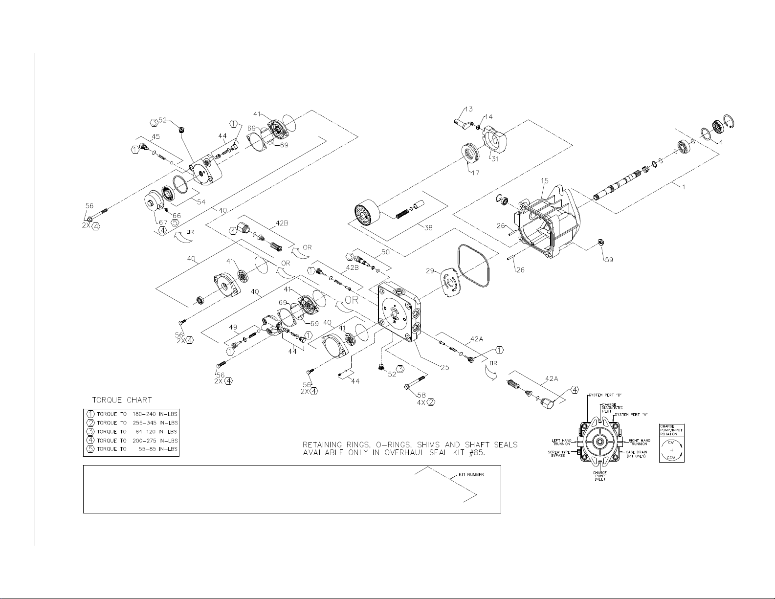
Figure 32 . BDP-21L
For Husqvarna Parts Call 606-678-9623 or 606-561-4983
BDP-10A/21L
BRACKETS INDICATE ITEMS INCLUDED IN KITS.
ITEMS IN KITS CANNOT BE ORDERED SEPARATELY.
Page 32
BDP-10A/21L
For Husqvarna Parts Call 606-678-9623 or 606-561-4983
ITEMS LIST BDP 21L
Part numbers are not provided in this manual. See microfiche or parts manual for part numbers.
No. Description
1 Pump Shaft
(19T Spline)
(Closed Key)
(Thru Shaft Spline)
(Double Taper-Single Key)
4 Spacer
13 Trunnion Arm
14 Slot Guide
15 Housing Kit
17 Thrust Ball Bearing Assembly
25 Endcap Kit
W/ Poppets
Endcap Kit
(W/ Poppets, .078" Cooling Orifice)
W/SCR'S
Aux W/ Poppets
Aux W/ SCR'S
26 Pin
29 Valve Plate
31 Variable Swashplate
38 Cylinder Block Kit
40 Charge Pump Kit
(0.19 STD Splined)
(0.13 STD Splined)
(0.13 STD Thru Shaft)
(0.13 STD Spline, Clear Zinc Cover)
(CW - Splined Aux, 40-70 psi)
(CW - Splined Aux, 135-165 psi)
(CCW - Splined Aux, 40-70 psi)
(AL Aux, 7/16 SAE Port, 40-70 psi)
(AL Aux, 7/16 SAE Port, (75-105 psi)
41 Gerotor Assembly (0.19 in3/rev)
Aux Gerotor & HSG Assembly (0.19
in3/rev)
Gerotor Assembly (0.13 in3/rev)
No. Description
42 Check Valve Kit
(0.031")
(0.044")
(Blank)
System Check/Relief Kit
44 Charge Relief Kit
(W/ 1/2 SAE Valve Plug, 40-70 PSI)
(W/ 1/2 SAE Valve Plug, 135-165 PSI)
(W/ 9/16 SAE Valve Plug)
(W/ 9/16 SAE Valve Plug, 75-105 PSI)
(7/32" Plastic Ball & 50654 Spring)
(1/4 Plastic Ball & 2000029 Spring)
(1/4 Plastic Ball & 50654 Spring)
45 Aux Relief Valve Kit
49 Aux Bypass/Check Kit
50 Bypass Valve Kit
(Blank)
(0.031")
52 Std Plug
54 Auxiliary Filter Kit
56 Hex Screw, 5/16-18 x 1.0
Hex HD CAP Screw, 5/16-18 x 1.38
Flange HD Screw, 5/16-18 x 2.5
58 Hex Screw, Flanged Head
59 HEX Flange Nut
66 5/16 SAE Plug
67 Filter Cover
69 Pin
85 Overhaul Seal Kit
Table 6. BDP-21L
32
www.mymowerparts.com
Page 33
33
www.mymowerparts.com
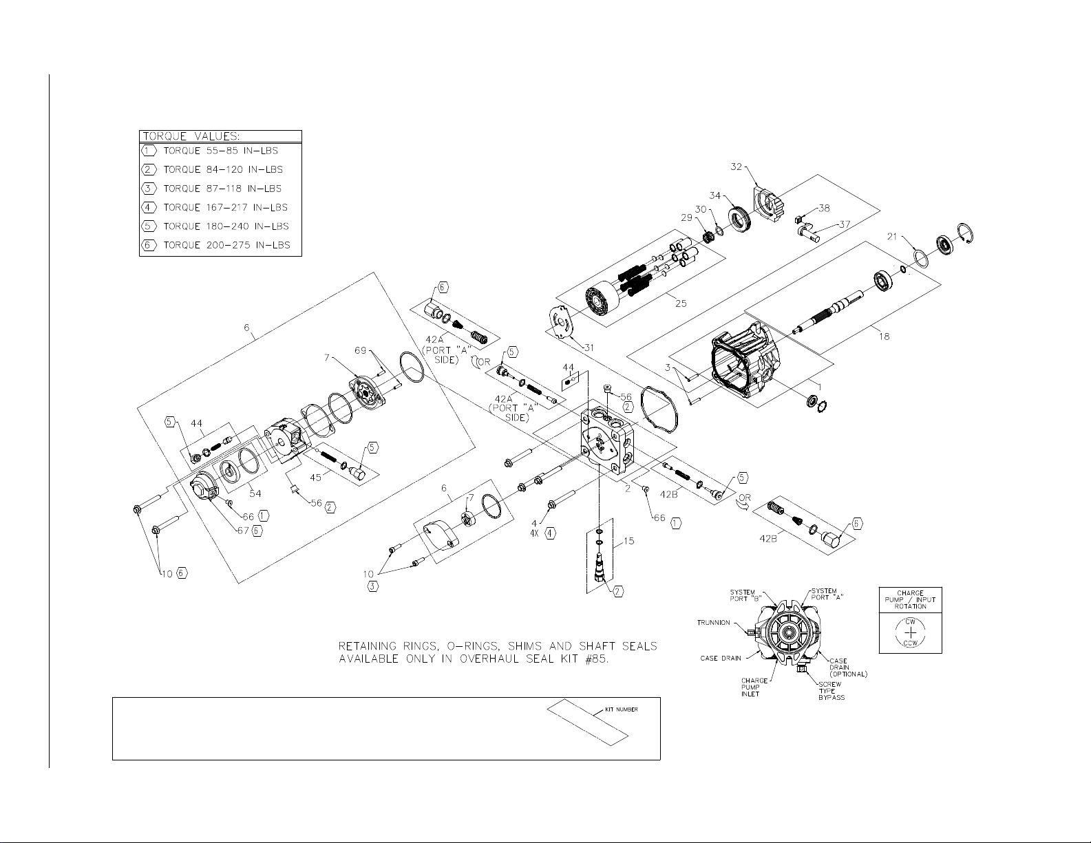
Figure 33 . BDP-10A
For Husqvarna Parts Call 606-678-9623 or 606-561-4983
BDP-10A/21L
BOXES INDICATE ITEMS INCLUDED IN KITS.
ITEMS IN KITS CANNOT BE ORDERED SEPARATELY.
Page 34

BDP-10A/21L
For Husqvarna Parts Call 606-678-9623 or 606-561-4983
ITEMS LIST BDP 10A
Part numbers are not provided in this manual. See microfiche or parts manual for part numbers.
No. Description
1 Housing Kit
2 End Cap Kit (W/ Poppets, Standard Charge)
End Cap Kit (W/ SCR'S, Standard Charge)
End Cap Kit (W/ Poppets, Auxiliary Charge)
End Cap Kit (W/ SCR'S & Auxiliary Charge)
3 Straight Headless Pin
4 Socket Head Screw
6 Charge Pump Kit (STD)
Aux Pump Kit (Splined, 7/16” SAE Ports)
Aux Pump Kit (Splined, 7/16” SAE Ports, Aux Poppet)
Aux Pump Manifold (AL, SAE Ports)
7 Gerotor Assembly
10 Socket Head Screw
Hex Flange Bolt 8M-1.25 x 60mm
15 Bypass Valve Kit (Blank)
Bypass Valve Kit (0.031")
Bypass Valve Kit (0.043")
18 Pump Shaft (Blind 15MM Keyway W/ Std Chg)
Pump Shaft Kit (Blind15MM Keyway W/ Std Chg)
Pump Shaft (Blind 15MM Keyway W/ Aux Chg)
Pump Shaft Kit (Blind 15MM Keyway W/ Aux Chg)
Pump Shaft (9 Tooth W/ Std Chg)
Pump Shaft Kit (9 Tooth W/ Std Chg)
Pump Shaft (9 Tooth W/ Aux Chg)
Pump Shaft Kit (9 Tooth W/ Aux Chg)
21 Spacer
25 Cylinder Block Kit
29 Block Spring
30 Block Thrust Washer
31 Valve Plate
32 Swashplate
34 Ball Thrust Bearing
37 Trunnion Arm
38 Slot Guide
42 Check Valve Kit (Blank Orifice)
Check Valve Kit (0.024" Orifice)
Check Valve Kit (0.031" Orifice)
Check Valve Kit (0.044" Orifice)
System Check / Relief Kit
44 Charge Relief Valve Kit (1/4" Steel Ball)
Charge Relief Valve Kit (w/9/16" SAE Plug)
45 Aux Relief Valve Kit (1/4"Ball)
Aux Relief Valve Kit (Aux Poppet)
54 Auxiliary Filter Kit
No. Description
56 Straight Thread Plug
66 5/16" SAE Plug
67 Filter Cover
69 Straight Headless Pin
85 Overhaul Seal Kit
Table 7 . BDP-10A
34
www.mymowerparts.com
Page 35

GLOSSAR
Y
OF TERMS
For Husqvarna Parts Call 606-678-9623 or 606-561-4983
Axial Piston: Type of design for hydraulic motors and pumps in which the pistons are arranged
parallel with the spindle (input or output shaft).
Bantam Duty: A descriptive term relating to the product capacity (meaning: light duty).
Bypass Valve: A valve whose primary function is to open a path for the fluid to bypass the motor or
pump. Also referred to occasionally as the freewheel valve or dump valve.
Case Drain Line (Return Line): A line returning fluid from the component housing to the reservoir.
Cavitation: A phenomenon of boiling in a flowing liquid at normal temperatures, as a result of low
pressure condition. The gas liberated from the fluid implodes rapidly and damages pump components.
Center Section: A device which acts as the valve body and manifold of the transmission.
Charge Pump: A device which supplies replenishing fluid to the fluid power system (closed loop).
Charge Pressure: The pressure at which replenishing fluid is forced into a fluid power system.
Charge Relief Valve: A pressure control valve whose primary function is to limit pressure in the
charge circuit.
Check Valve: A valve whose primary function is to restrict flow in one direction.
Closed Loop: A sealed and uninterrupted circulating path for fluid flow from the pump to the motor
and back.
Decay Rate: The ratio of pressure decay over time.
End Cap: See “Center Section”
Entrained Air: A mechanically generated mixture of air bubbles having a tendency to separate from
the liquid phase.
Gerotor: A fixed displacement pump frequently used as a charge pump.
Hydraulic Motor: A device which converts hydraulic fluid pressure and flow into mechanical force
and motion.
Hydraulic Pump: A device which converts mechanical force and motion into hydraulic fluid pres-
sure and flow.
Hydrostatic Motor: See “Hydraulic Motor”
Hydrostatic Pump: See “Hydraulic Pump”
35
BDP-10A/21L
www.mymowerparts.com
Page 36

BDP-10A/21L
For Husqvarna Parts Call 606-678-9623 or 606-561-4983
Hydrostatic Transaxle: A multicomponent assembly including a gear case and a hydrostatic trans-
mission.
Hydrostatic Transmission: The combination of a hydraulic pump and motor in one housing to form
a device for the control and transfer of power.
Inlet Line: A supply line to the pump.
Integrated Hydrostatic Transaxle (IHT): The combination of a hydrostatic transmission and gear
case in one housing to form a complete transaxle.
Manifold: A conductor which provides multiple connection ports.
Neutral: Typically described as a condition in which fluid flow and system pressure is below that
which is required to turn the output shaft of the motor.
Pressure Decay: A falling pressure.
Priming: The filling of the charge circuit and closed loop of the fluid power system during start up,
frequently achieved by pressurizing the fluid in the inlet line.
Purging: The act of replacing air with fluid in a fluid power system.
Rated Flow: The maximum flow that the power supply system.
Scoring: Scratches in the direction of motion of mechanical parts caused by abrasive contami-
nants.
Swash Plate: A mechanical device used to control the displacement of the pump pistons in a fluid
power system.
System Charge Check Valve: A valve controlling the replenishing flow of fluid from a charge circuit
to the closed loop in a fluid power system.
System Pressure: The pressure which overcomes the total resistance in a system, including all
efficiency losses.
Valve: A device which controls fluid flow direction, pressure, or flow rate.
Variable Displacement Pump: A pump in which the displacement per revolution can be varied.
Volumetric Displacement: The fluid volume for one revolution.
36
www.mymowerparts.com
 Loading...