

Page 1
SERVICE MANUAL
Printed in Sweden
Made in Sweden
Jan-2002
Designer I
Designer II
Quilt Designer
104 72 53-26
Replaces 104 72 50-26
Page 2

Contence
Directions for use 4
ESD 4
Service tools 5
SETTINGS 6
1. The play of the hook gear 7
2. Setting the hook in relation to the feeding eccentric (after feeding) 8
3. Belt tension, arm/lower shaft belt 9
4. Belt tension, motor belt 9
5. Setting the feeding unit sideways 1 0
6. Basic setting - the step motor of the needle 11
7. Setting of the needle in relation to the presser foot 1 3
8. The gap between the needle and the hook 14
9. The timing of the hook in relation to the needle 1 5
10. The needle height 16
1 1. Presser foot parallelism to the feed dog 17
12.Presser foot height to the stitch plate 1 7
13. Setting the stitch plate (the hook cover) in relation to the needle in the feeding direction. 1 8
14. The sideways setting of the stitch plate (the hook cover) in relation to the presser foot. 1 8
15. The height of the hook 19
16.Pre-setting of the step motor for the side feeding 2 0
17.Setting the feeding mechanism sideways 21
18. Feed dog height 22
19.Threading device 23
20.Stitch length balance basic setting 2 4
21. Pre-setting the step motor of the feed dog 2 5
22.Stitch length balance 2 6
23. Lower thread tension (thread tension of the bobbin case) 27
24.Upper thread tension - Position "Norm" - Designer I 2 8
24.Upper thread tension - Position "Norm" - Designer II and Quilt Designer 29
25. Upper thread tension - Position "Embr/Dec" - Designer I 3 0
25. Upper thread tension - Position "Embr/Dec" - Designer II 3 1
25. Upper thread tension - Position "Decor" - Quilt Designer 3 2
26. Upper thread guard sensor 33
27. Setting the thread take-up spring 3 4
28. Disconnection when winding the bobbin 35
29. Pivot height 36
SERVICE PROGRAM
Service program - Designer I 37
Functions of the service menu 2 - Designer I -Sensor check 4 0
Functions of the service menu 3 - Designer I - Upper thread tension 4 1
Calibration of the touch panel - Designer I 42
Update of the memory - Designer I 43
Service program Designer II 44
Functions of the service menu 2 - Designer II 4 7
Sensor check - Function of the Service menu 1 4 7
Functions of the service menu 3 - Designer II. 4 8
Upper thread tension and Pivot position 48
Functions of the Service Menu 4 - Designer II 48
Log menu 48
Calibration of the touch panel - Designer II 49
Update of the memory - Designer II (Read & write unit) 5 0
Service program for Quilt Designer 51
Functions of the service menu 2 - Sensor check 5 4
Function of the Service menu 1 54
Functions of the service menu 3 - Quilt Designer 5 5
2
104 72 53-26
Page 3

Upper thread tension - Pivot position 55
Functions of the Service Menu 4 - Log menu 55
Calibration of the touch panel - Quilt Designer 56
Update of the memory - Quilt Designer (Read & write unit) 5 7
DEMOUNT AND MOUNTING
Upper rear cover 58
Lower rear cover 58
Front cover - Designer I 59
Parts of the front cover - Designer I 6 0
Front cover - Designer II and Quilt Designer 61
Parts of the front cover - Designer II and Quilt Designer 6 2
Presentation Unit 62
Presentation Unit - d-Card Connection board 62
Presentation Unit - Display board 62
T ouch Panel 62
Base Plate 63
Transformer- Designer I, Designer II 6 4
Transformer- Quilt Designer 65
Circuit board - Circuit diagram - Designer I 6 6
Circuit board - Circuit diagram - Designer II 67
Circuit board - Circuit diagram - Quilt Designer 6 8
Stop right circuit board 69
Sewing head 70
The step motor of the needle 71
The step motor of the presserfoot lifter 72
The thread tension compl. 73
The hook cover compl, step motor house. 7 4
Parts of the hook cover compl.- Designer I and Designer II 7 5
Feeding unit 76
Feed dog. 77
The side feeding mechanism complete 78
The side feeding mechanism step motor 7 8
The feeding unit step motor 79
Hook compl. 80
Bobbin winding device 81
Cover Y-slide 82
Step motor cover 82
Cover upper part 83
Cover lower part 83
Locker switch 83
EMBROIDERY UNIT
Embroidery unit - X-unit 8 4
Belt tension 84
Calibration of the end position, X-unit. 84
Embroidery unit - Y-unit 8 5
Belt tension 85
Calibration of the end position, Y -unit. 85
Hoop holder 86
The hoop sensor. 86
Step motor, Y-unit 87
Step motor , X-unit 87
FAUL T FINDING
Fault finding diagram D I 88
Fault finding diagram D II 89
Fault finding diagram D I / DII 90
Fault finding diagram D I / DII 91
Fault finding diagram D I / DII 92
104 72 53-26
3
Page 4
Directions for use
These service instructions are intended to be used by service workshop personnel, or by
salesmen who carry out servicing their own districts. They assume a thorough knowledge
of the handling of precision appliances and accessibility to service tools.
The manual is divided into two sections and covers all service operations and checks
which should be carried out when making a complete overhaul of a sewing machine.
The first section deals with the various settings which must be maintained to ensure that
the machine functions satisfactorily .
The second section covers dismantling and mounting instructions.
The diagrams only give indication as to where the detail or mechanism is located in
the machine. For more detailed information regarding the construction, etc., refer to
the diagrams in the spare parts list.
ESD
A TTENTION!
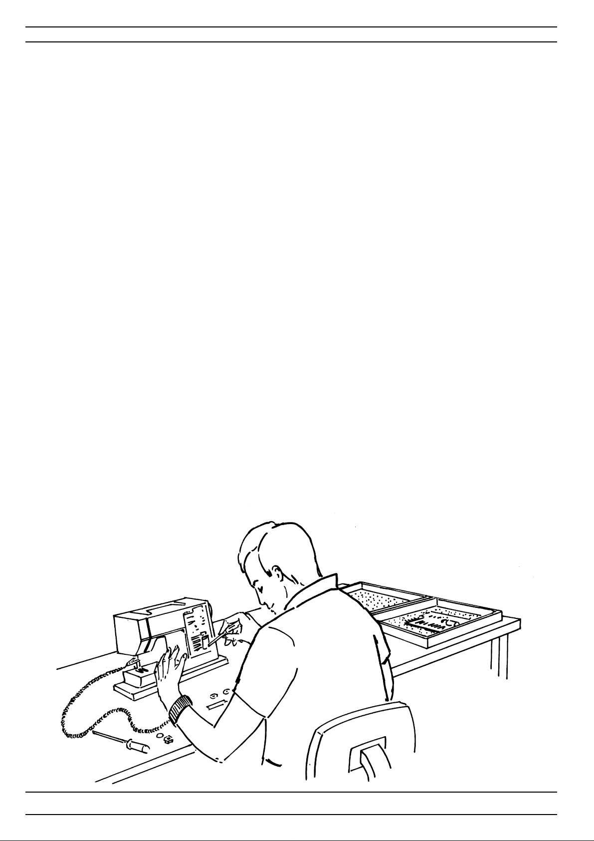
It is of the utmost importance that precautions are being taken in order to avoid damage
of the electronics by electro static discharges ESD (=Electro S tatic Discharge). To avoid
that these errors arise it is important to handle loose circuit boards in a controlled way .
Always use wrist band 412 23 02-01 when servicing.
4
104 72 53-26
Page 5
Service tools
A reasonable requirement in a domestic sewing machine is that it should able to sew all
types of fabrics used in the home. The settings made when assembling and sewing-in
the machines are those most suited to give the best results in the majority of fabrics and
fabric combinations. In doing so, consideration has been given to the requirements of
different markets. This does, however , mean that when sewing extreme fabrics, better
results may be obtained in certain cases by altering the settings. It must be pointed out
that these altered settings can cause poorer results on more normal fabrics. How
the different standard ratings are set can be seen from the description under each
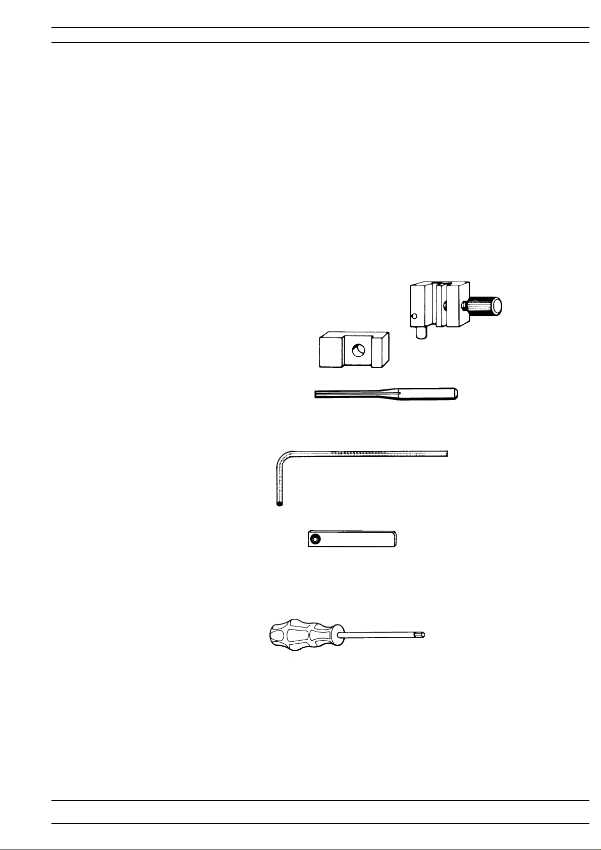
setting instruction. The following list of setting gauges and service tools is intended as
an instruction about the special service tools needed to servicing this machine.
1. On several different occasions the needle is
used as a setting gauge.
The setting ratings are adapted to needle 90.
Make sure to use an undamaged needle.
2. Gauge for setting the timing of the hook in
relation to the needle .
Ref. No 41 1 17 52-01.
3. Gauge for the feed dog lift.
Ref. No 41 1 49 93-01.
4. Gauge for the needle height .
Ref. No 412 35 29-01.
5. Adam key - Shortened 2.5 mm
Ref. No 412 27 65-01
6. Adam Key 2 mm
Ref. No 41 1 86 00-01
7. Adam key 1.5 mm
Ref. No 41 1 66 89-01
8. Distance gauge 0.05-1,00 mm
Ref: No. 412 38 85-01
9. Angel key T orx 6
Ref No 412 27 67-01
10. Angel key T orx 8
Ref No 412 68 04-01
1 1. Screwdriver T orx 10
Ref. No 412 36 48-01.
12. Screwdriver T orx 20
Ref. No 412 36 49-01.
13. Screwdriver T orx 25
Ref. No 412 36 50-01
14. Cable for service -Designer I 15. Calibration of touch panel
Ref. 412 66 04-01 Ref. No 412 22 33-01
16. Service d-Card Designer II and Quilt Designer
Ref. 412 66 96-01
104 72 53-26
5
Page 6
SETTINGS
23
6
104 72 53-26
Page 7
Settings
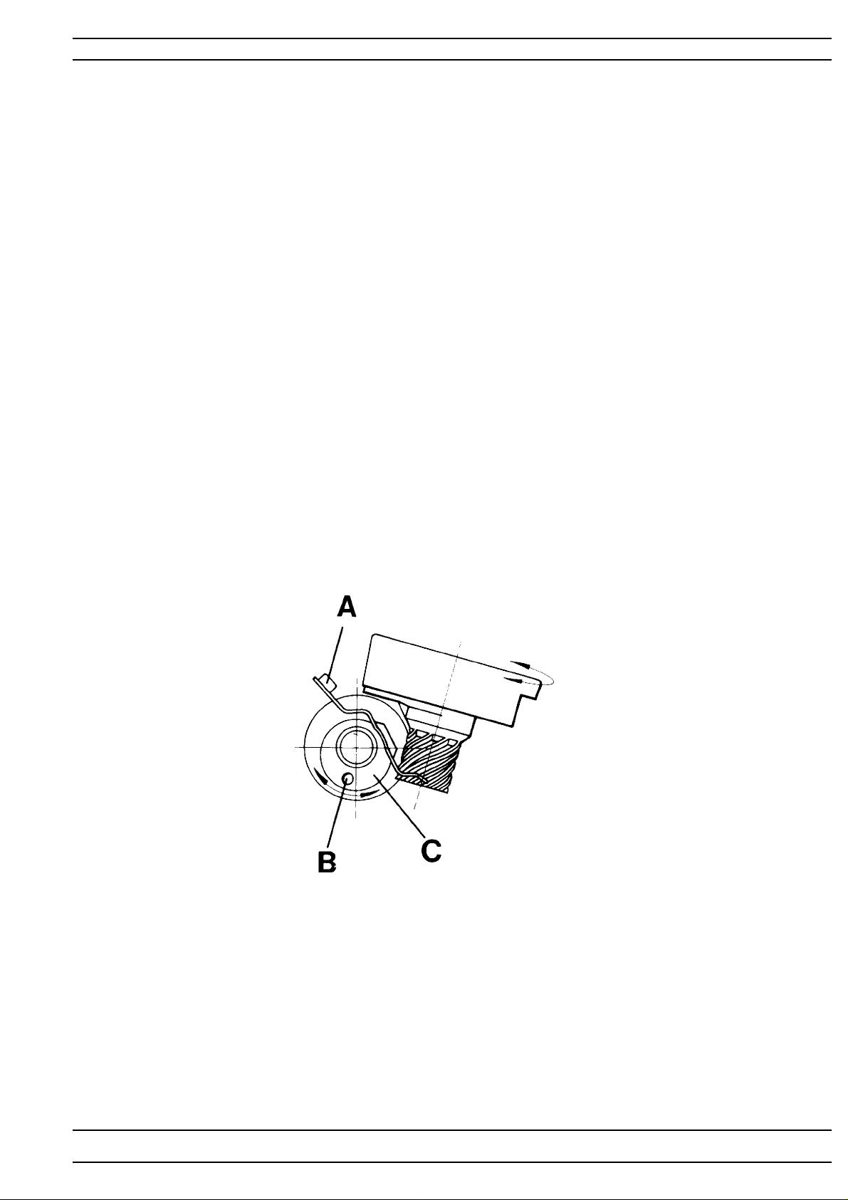
1. The play of the hook gear
It is impossible to obtain an equally large play in one rotation of the cog wheel, but it
should be as small as possible at the tightest spot during the revolution.
Check
1. Rotate the hook back and forth and check the play .
2. Do this check on at least 3 different spots during the revolution of the cog wheel.
(Move the cog wheel with the hand wheel).
Adjustment
1. Loosen, screw (A) in the bearing clamp
2. The play can now be adjusted by turning the eccentric bearing (C).
NOTE! The hole (B) in the bearing shall always be on the lower half.
104 72 53-26
7
Page 8
Settings
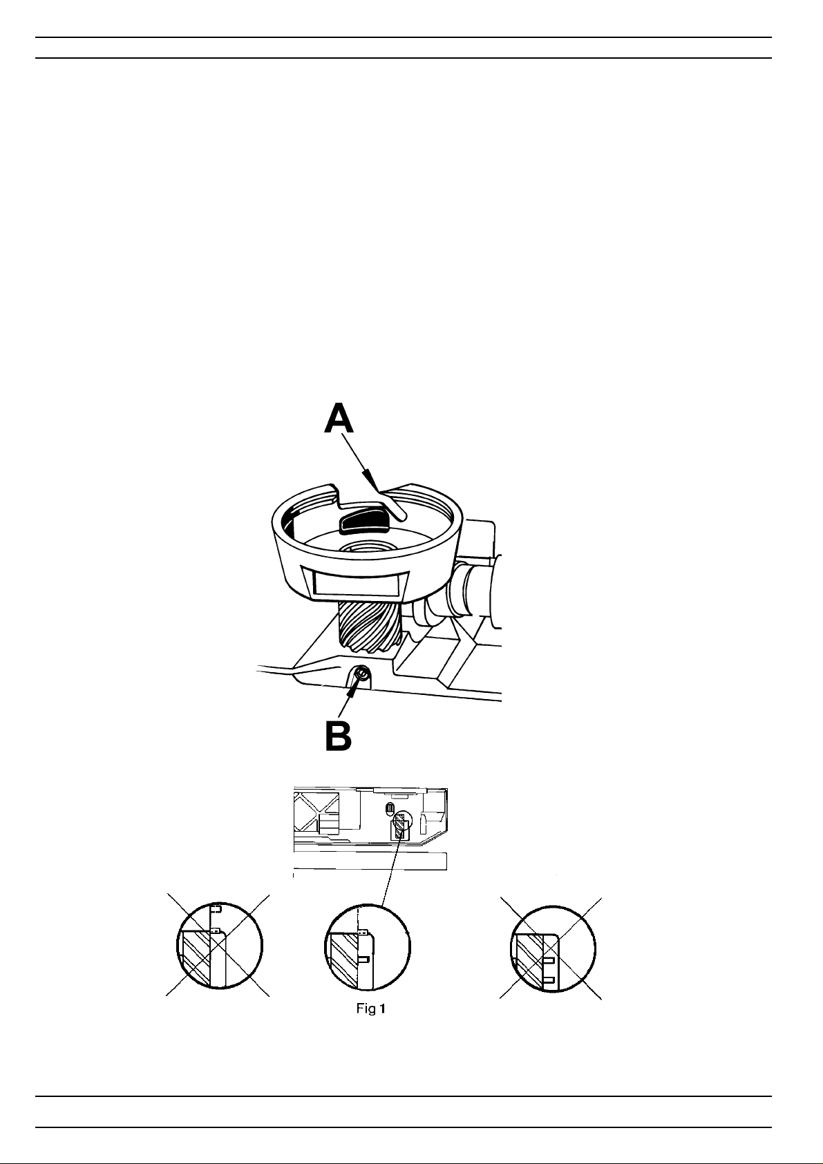
2. Setting the hook in relation to the feeding eccentric (after feeding)
Check
1. The needle shall be in its centre position, straight stitching.
2. Set the tip of hook (A) so is centred behind the needle, the tap of the worm gear
should now be positioned according to fig. 1.
Note! The position of the upper pin shall be aligned with the frame opening.
Alt. Check
1. When the two taps of the worm gear are positioned according to fig. 1 the tip (A) of the hook should point
straight backwards.
Note! The position of the upper pin shall be aligned with the frame opening.
Adjustment
1. Loosen screw (B). Remove the hook and set it into its correct position.
Note! The position of the upper pin shall be aligned with the frame opening.
8
104 72 53-26
Page 9
Settings
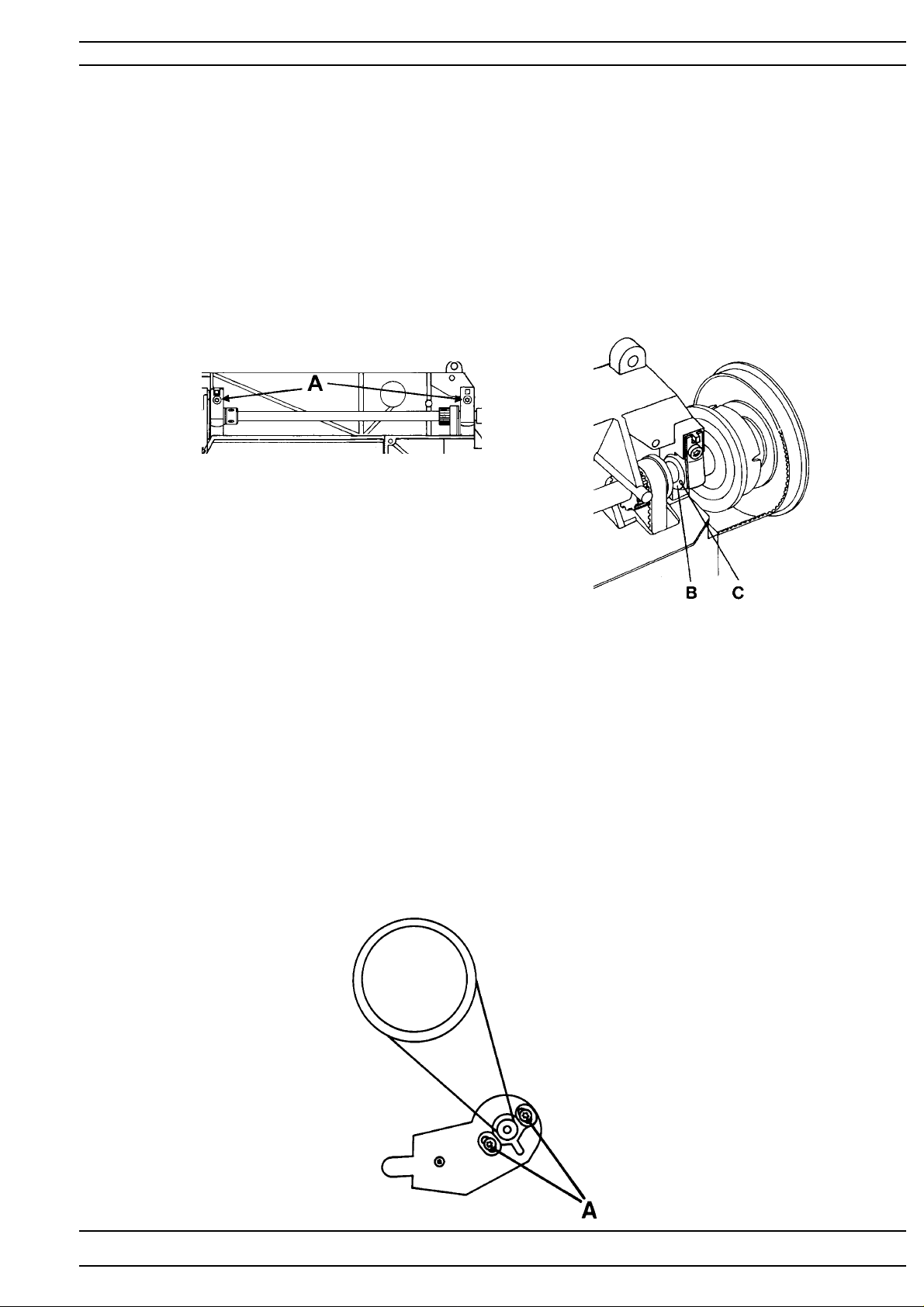
3. Belt tension, arm/lower shaft belt
1. Dismount rear cover and front cover.
2. Dismount the bobbin winding device.
3. Loosen the two screws (A) of the bearing clamps.
4. The belt tension can now be adjusted by turning bearing (B) which is eccentric.
NOTE! The hole (C) should always be on the front half.
4. Belt tension, motor belt
1. Dismount rear cover .
2. Loosen the 2 screws (A) and adjust the belt tension by displacing the motor.
NOTE! The adjustment of the arm/lower shaft belt affects this adjustment.
104 72 53-26
9
Page 10
Settings
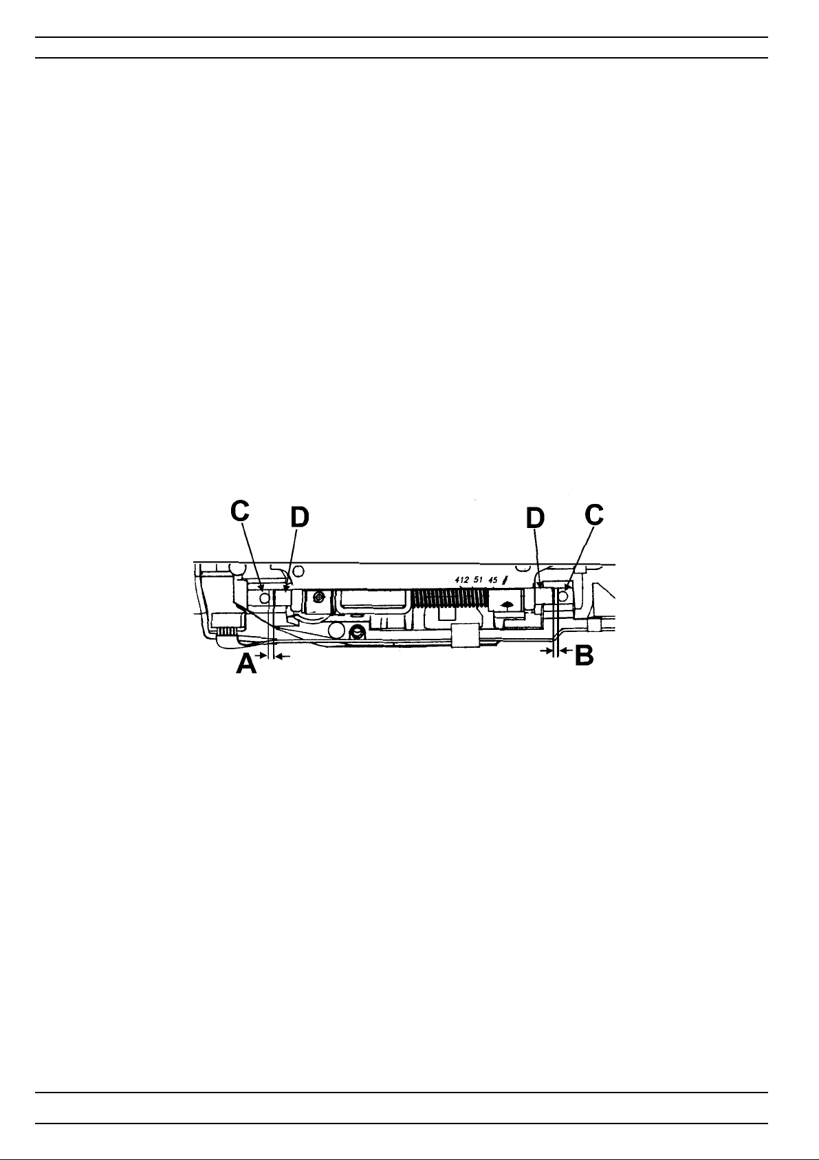
5. Setting the feeding unit sideways
Check
1. The distance A and B shall be equal between the screw (C) and
the edge of feeding device shaft (D).
Adjustment
1. Loosen the 2 screws in the feeding device.
2. Move the feeding device sideways until the distance A and B is equal between
the screws (C) and the edge of feeding device shaft (D)
3. Tighten the screws.
10
104 72 53-26
Page 11
Settings
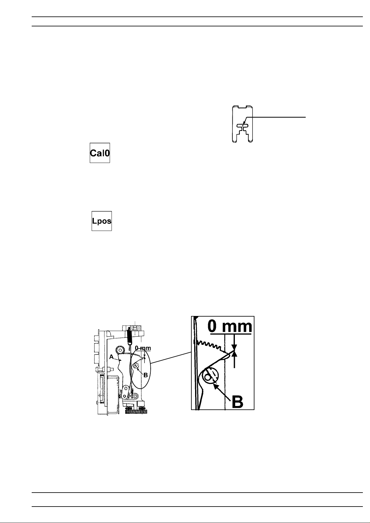
6. Basic setting - the step motor of the needle
Check
1. Insert a new needle size 90 universal in the machine.
2. Set the needle in its upper turning position.
3.The needle should always get to the centre position, when the main
switch is turned on repeatedly .
Check
Go to the service program of the machine.
The needle should be in its upper turning position.
T ouch Needle -
The needle should now take its centre position in the
presser foot.
Touch Needle -
The needle shall now take its left position.
The gap between the segment (A) and the calibration stop (B)
should now be zero (0 mm).
Note! The position of the eccentric.
Needle point
104 72 53-26
11
Page 12
Settings
Adjustment
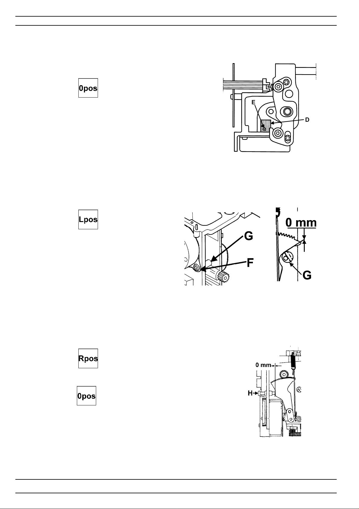
Go to the service program of the machine.
The needle should be in its highest position.
T ouch Needle -
Loosen screw (E) in the cog wheel (D) on the step motor shaft.
Turn the cog wheel until the needle is in the centre of
the presser foot.
T ouch Needle -
Loosen screw (F) in the calibration stop (G) and
turn it until the gap is correct (0mm).
Note! The position of the eccentric.
T ouch Needle - , row 1 .
Turn the screw (H) until the gap is correct (0 mm).
This setting is only a sideways limitation.
Touch Needle - , row 1
The needle should now take its centre position into the needle
hole of the presser foot.
12
104 72 53-26
Page 13
Settings
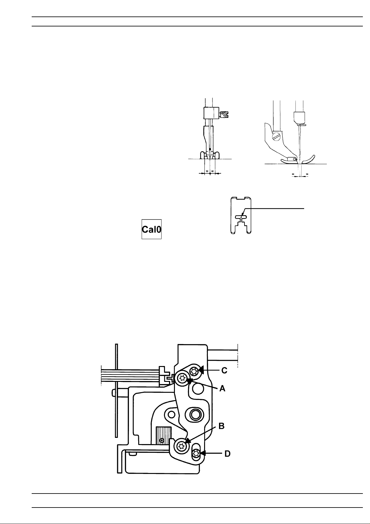
7. Setting of the needle in relation to the presser foot
Check
Insert a new needle size 90 universal in the machine.
When the machine is set at straight stitching centre position, the needle bar shall be set in
such a way that a needle 90 passes through the centre of the needle hole in
the presser foot.
1 = seen from the front
2 = seen from the side
1
Adjustment
1. Turn on the main switch
Keep the machine set at straight stitching centre position
alt. service menu 1, touch Needle- ,
2. Loosen the two screws (A) and (B).
Move the needle bar with the two eccentric screws (C) or (D) until
the requirement is obtained.
- The length movement is adjusted by moving the eccentric screw (C)
- The side movement is adjusted by moving the eccentric screw (D)
3. Tighten the screws (A) and (B).
4. Check the setting by turning the main switch on and off a couple of times.
NOTE! "The Setting of the needle in relation to the presser foot" affects the function
of "6. Basic setting - the step motor of the needle".
2
Needle point
104 72 53-26
13
Page 14
Settings
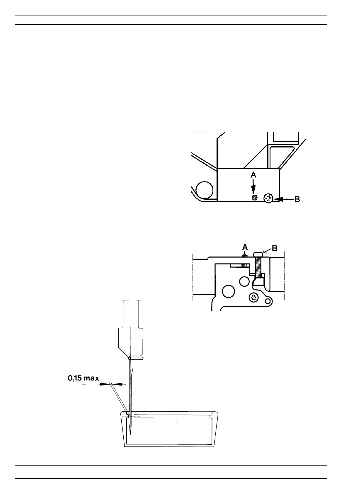
8. The gap between the needle and the hook
Check
1. Set the machine on straight stitching.
2. Insert a new needle size 90 universal in the machine.
3. Rotate hand wheel until the tip of the hook arrives behind the needle.
Check the gap by pressing a small screw driver against the needle.
The gap should be as small as possible, but max 0.15 mm.
Adjustment
If the gap is too large:
1. Loosen the screw (A).
2. Turn screw (B) clockwise until the needle
touches the tip of the hook
3. Turn screw (A) until the gap is correct
If the gap is too small:
1. Loosen the screw (B)
2. Turn screw (A) to make the gap larger
and then loosen the screw (A).
3. Turn screw (B) clockwise until the needle
touches the tip of the hook
4. Turn screw (A) until the gap is correct
NOTE! Always tighten screw (A).
Check!
14
104 72 53-26
Page 15
Settings
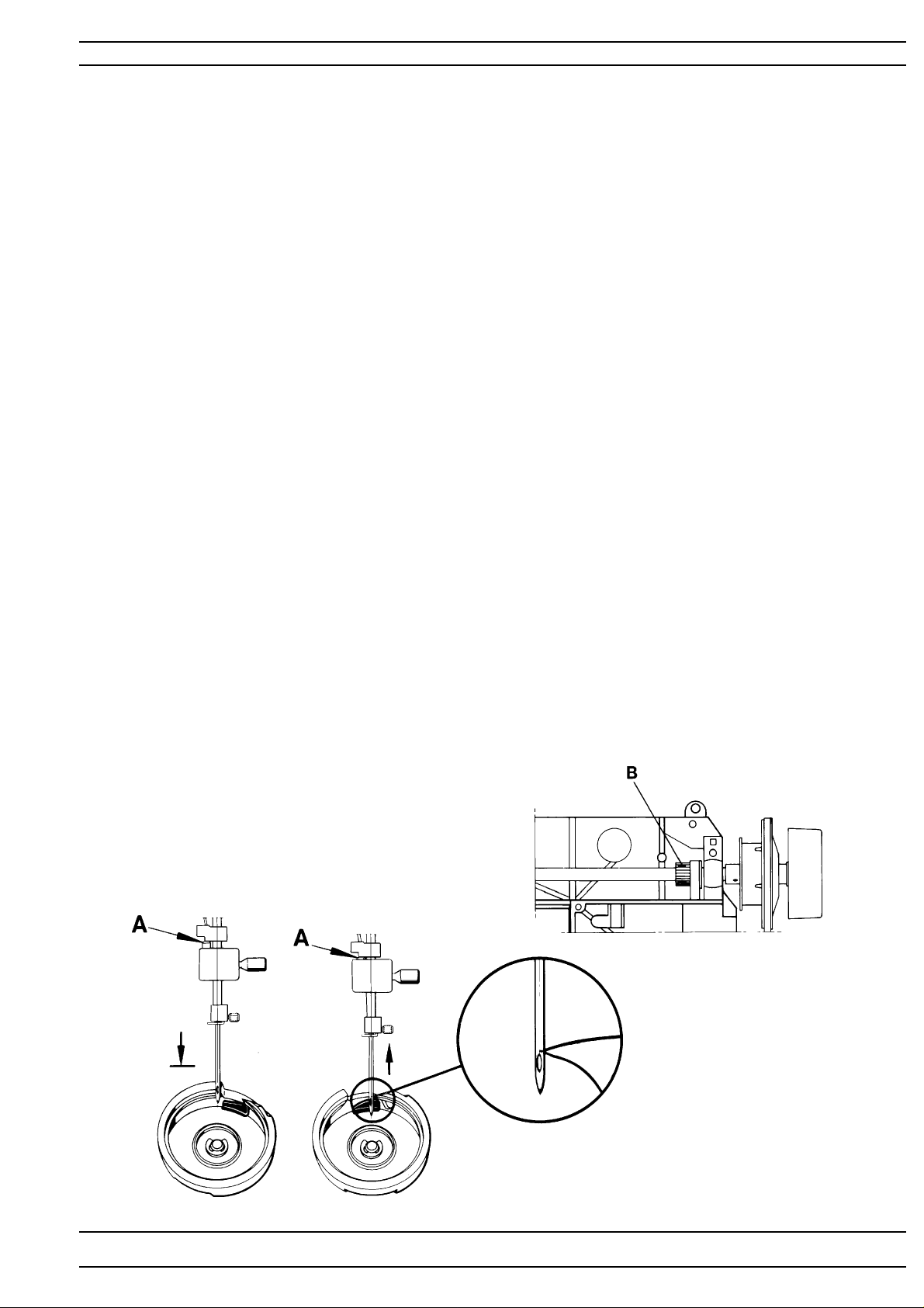
9. The timing of the hook in relation to the needle
Check
- Set a new needle size 90 universal into the machine
- Dismount the stitch plate, bobbin case holder and the bobbin case.
- Set machine on straight stitching.
- As the needle is moving upwards, the tip of the hook should pass
behind the centre of the needle, when the needle is 2.5 mm above
its lower turning position.
NOTE! Before any adjustment is done check that the setting
" 2. Setting the hook in relation to the feeding eccentric" is correct.
Check with setting gauge 411 17 52-01.
1. Turn the handwheel until the needle is at its lower turning position.
2. Place the setting gauge on the needle bar so that the springloaded
stud (A) just touches the needle bar frame and tighten the screw.
3. Move the needle upwards with the handwheel until the springloaded
stud (A) rests against its stop in the setting gauge.
4. The tip of the hook should now be behind the centre line of the needle.
Adjustment
1. Remove the blank pointed screw (B) and loosen the other 2 screws
in the belt wheel of the arm shaft.
2. Repeat checking points 1, 2 and 3 with setting gauge 41 1 17 52-01 .
3. Hold the arm shaft and turn the hook until its tip arrives behind
the centre line of the needle.
4. Tighten one of the black screws.
5. Make sure the screw descends into the groove of the shaft so that the
belt wheel is placed correctly sideways.
6. Check.
7. Tighten all the screws.
104 72 53-26
15
Page 16
Settings
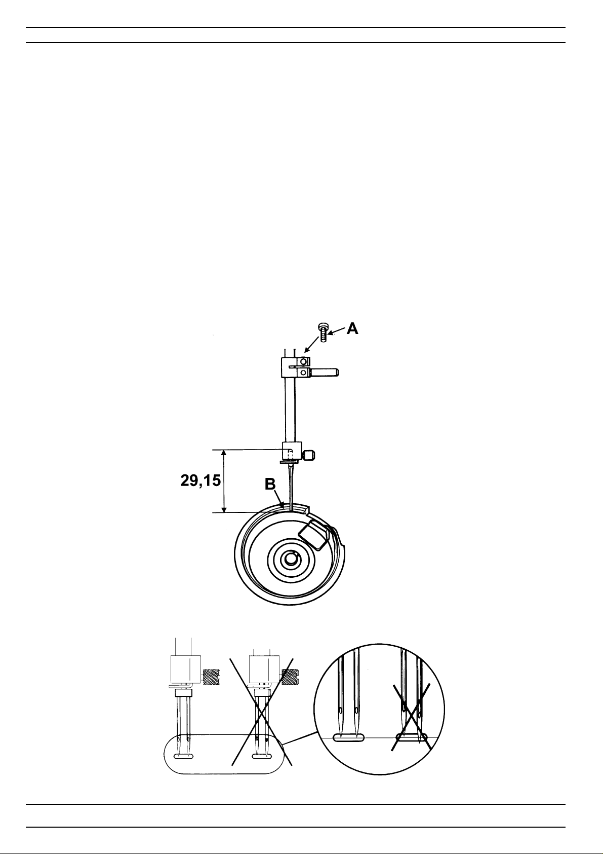
10. The needle height
Check
1. Bring the needle into its lower turning position.
2. The gap between the upper end of the needle and the surface (B)
of the hook ring should be 29.15 ± 0.2 mm.
The check is executed with a polished needle 90 which is 29.15 mm long.
Order nr. 412 35 29 - 01
Adjustment
1. Bring the needle to its lower turning position.
2. Loosen screw (A) and move the needle bar until the correct
measure is obtained.
3. Tighten the screw .
NOTE! Check by means of a twin needle that the needle bar is not
twisted. May cause jump stitches when sewing with a twin needle.
16
104 72 53-26
Page 17
Settings
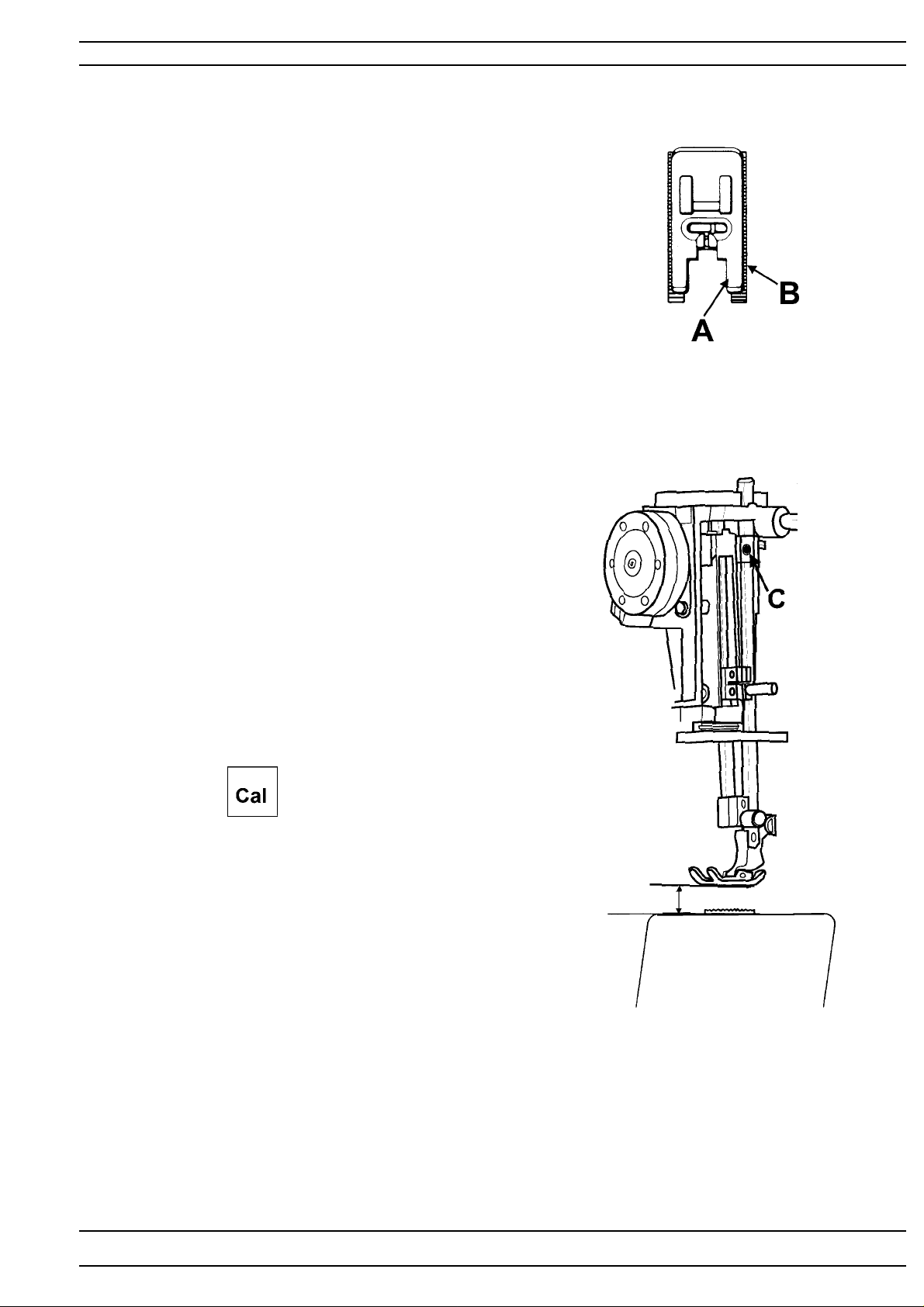
11. Presser foot parallelism to the feed dog
Check
The presser foot (A) should be parallel to the feed dog (B) .
Adjustment
1. Loosen screw (C) and turn the presser foot until
it is parallel to the feed dog.
2. Tighten the screw (C).
12.Presser foot height to the stitch plate
Check
When the pressar foot is in its highest lifting position it shall be
approx. 13 mm above the stitch plate.
Adjustment
1. Go to the service program
2. T ouch Servo -
The pressar bar now takes its highest lifting position.
3. Loosen screw (C) and move the presser bar until
the presser foot is approx. 13 mm above the stitch plate.
4. Tighten the screw (C).
Note! This setting affects:
1 1. Presser foot parallelism to the feed dog
29. Pivot height
13 mm
104 72 53-26
17
Page 18
Settings
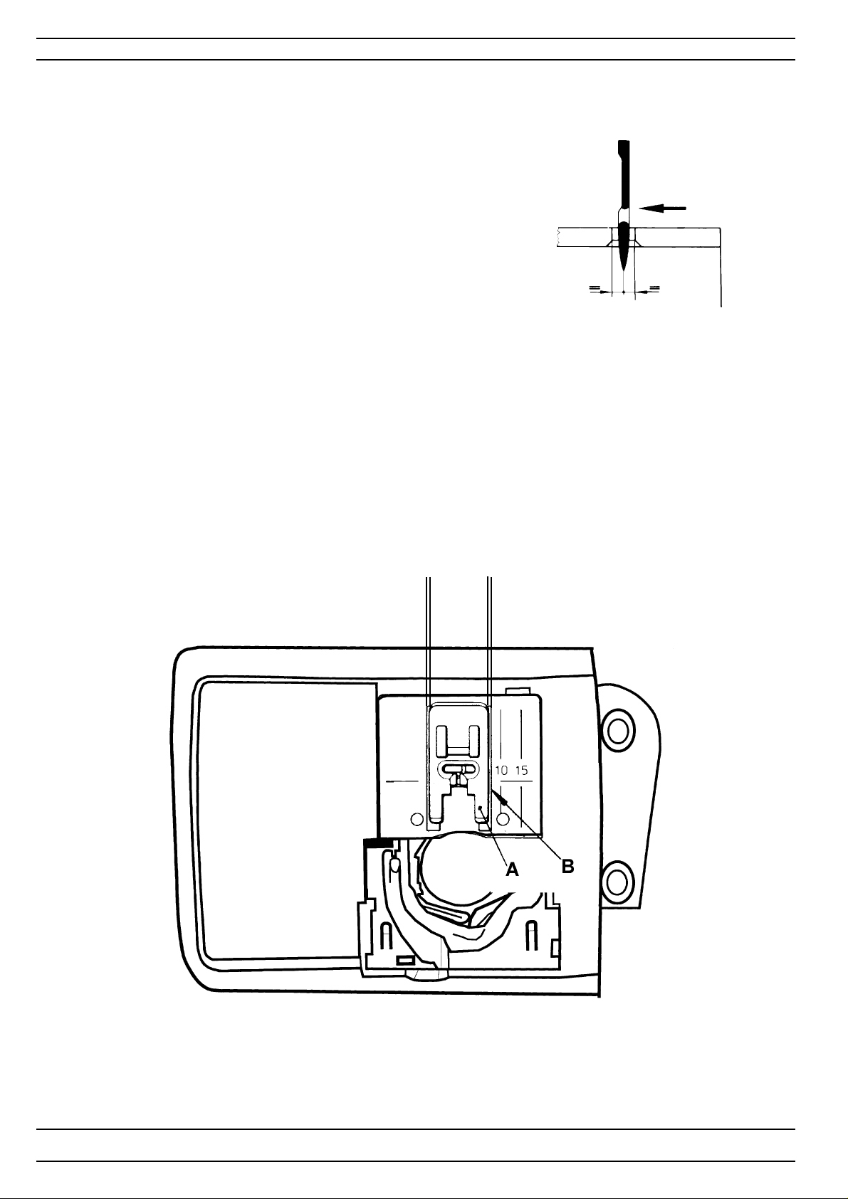
13. Setting the stitch plate (the hook cover) in relation to the needle in the feeding direction.
Check
1. Insert a new needle size 90 universal in the machine.
2. In the feeding direction the needle should descend right into the
middle of the needle hole of the stitch plate.
14. The sideways setting of the stitch plate (the hook cover) in relation to the presser foot.
Check
The presser foot (A) should be centred and parallel to the feed dog groove (B).
Adjustment
Loosen the 4 screws of the hook cover and move it so that:
- the needle in feeding direction decends in the middle of the stitch plate.
- the presser foot is centered and parallel to the feed dog groove .
18
104 72 53-26
Page 19
Settings
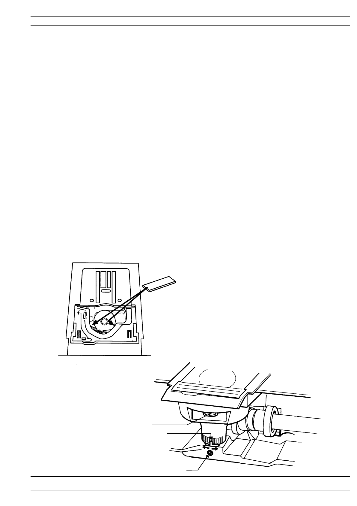
15. The height of the hook
Is checked between the bobbin case and the case holder
Check
The distance between the bobbin case and the case holder should
+ 0.1
be 0.5
The check is carried out at the tightest spot between the bobbin case and the case
holder. Check at the two marked positions according to fig. 1.
Adjustment
1. Loosen screw (A).
2. The gap between the hook and its cover can now be adjusted by turning the stud (C)
right or left.
3. When the adjustment is done. Remove stitch plate, bobbin case holder and bobbin case.
4. Push the hook shaft (B)downwards and tighten the screw (A).
5. Re-check.
Note! This setting affects: 1.The play of the hook gear.
mm.
-0,05
- To the right, the gap becomes larger.
- To the left, the gap becomes smaller..
9.The timing of the hook and the needle
10.The needle height
Check with distance gauge 412 38 85-01.
0,5 mm
Fig 1
104 72 53-26
B
C
A
19
Page 20
Settings
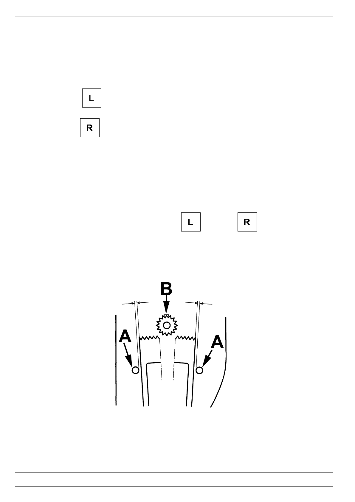
16.Pre-setting of the step motor for the side feeding
Check
1.Dismount the circuit board.
2. Dismount the side feeding unit.
3. Mount the circuit board.
4.Connect the side feeding unit. Hold the side feeding unit in your hand.
5.T ouch Side-M - . Turn the handwheel in such a way that the cog
segment changes between its 2 positions.
Touch Side-M - . T urn the handwheel in such a way that the
step motor changes between its 2 positions.
The distance between the pins (A) and the side of the segment shall be equally large
in both positions.
Note ! The movement of the segment is different from left position to the right position.
Adjustment
1. Loosen screw (B).
2. Adjust the cog segment in such way that the distance (A) between the pins and the side of the segment
is equally large in both positions.
NOTE! The adjustment must be done in both Side-M - and Side-M - postitions.
3.Tighten screw (B).
4. Re-check .
20
104 72 53-26
Page 21
Settings
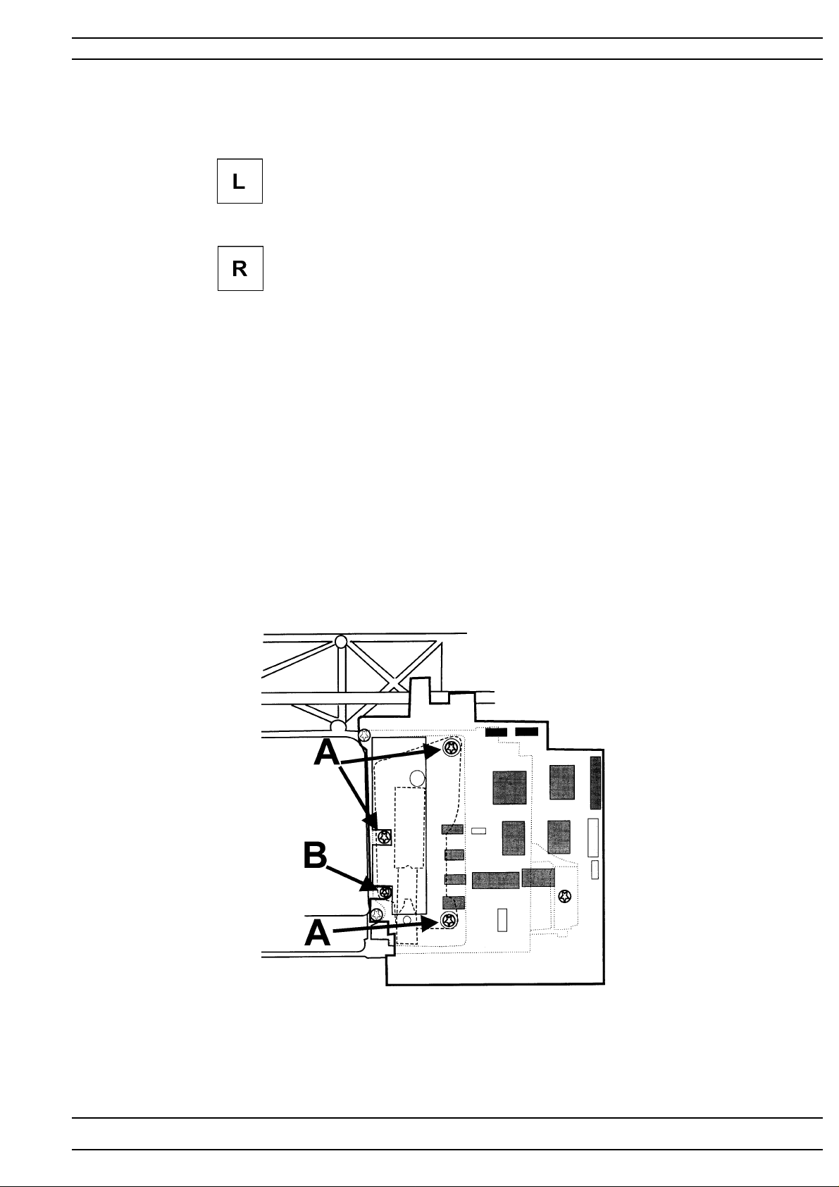
17.Setting the feeding mechanism sideways
Check
1. Go to the service program
2. T ouch Side-M - . Turn the handwheel in such a way that the step motor
changes between its 2 positions. The feed dog should not at any point touch the stitchplate.
3. T ouch Side-M - . Turn the handwheel in such a way that the step motor
changes between its 2 positions. The feed dog should not at any point touch the stitchplate.
Adjusment
1. Loosen the 3 screws (A), located behind the circuit board .
2. Move the feeding device sideways until a correct position of the feed dog is
accomplished by turning adjustment screw (B),located behind the circuit board .
3. Tighten the 3 screws (A).
4. Re-check the positions of the feed dog.
104 72 53-26
21
Page 22
Settings
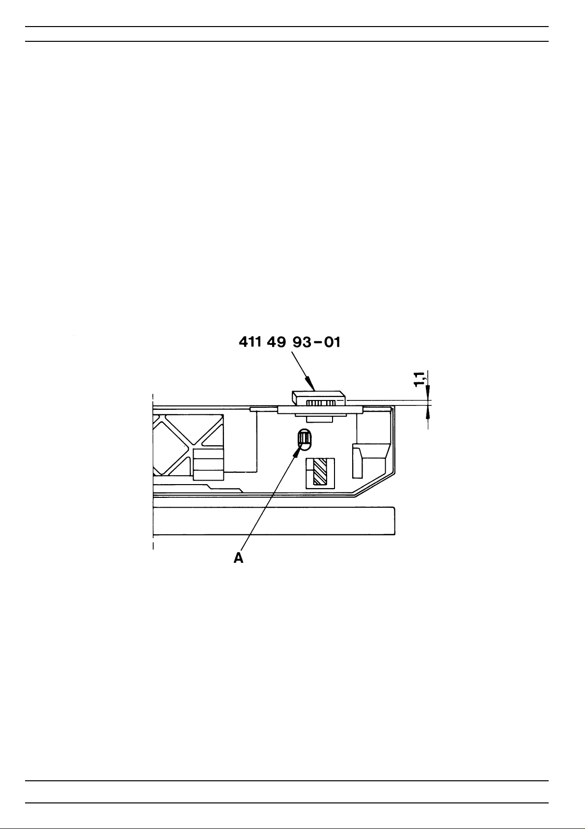
18. Feed dog height
Check
1. Bring the feed dog to its highest position.
2. The top of the feed dog should be 0.9-1.1 mm above the stitch plate.
Check with setting gauge 41 1 49 93-01
Adjustment
1. Bring the feed dog to its highest position.
2. Adjust with a screw driver the adjustment nut (A) until a correct
feed dog height (0.9-1.1 mm) is obtained.
22
104 72 53-26
Page 23
Settings
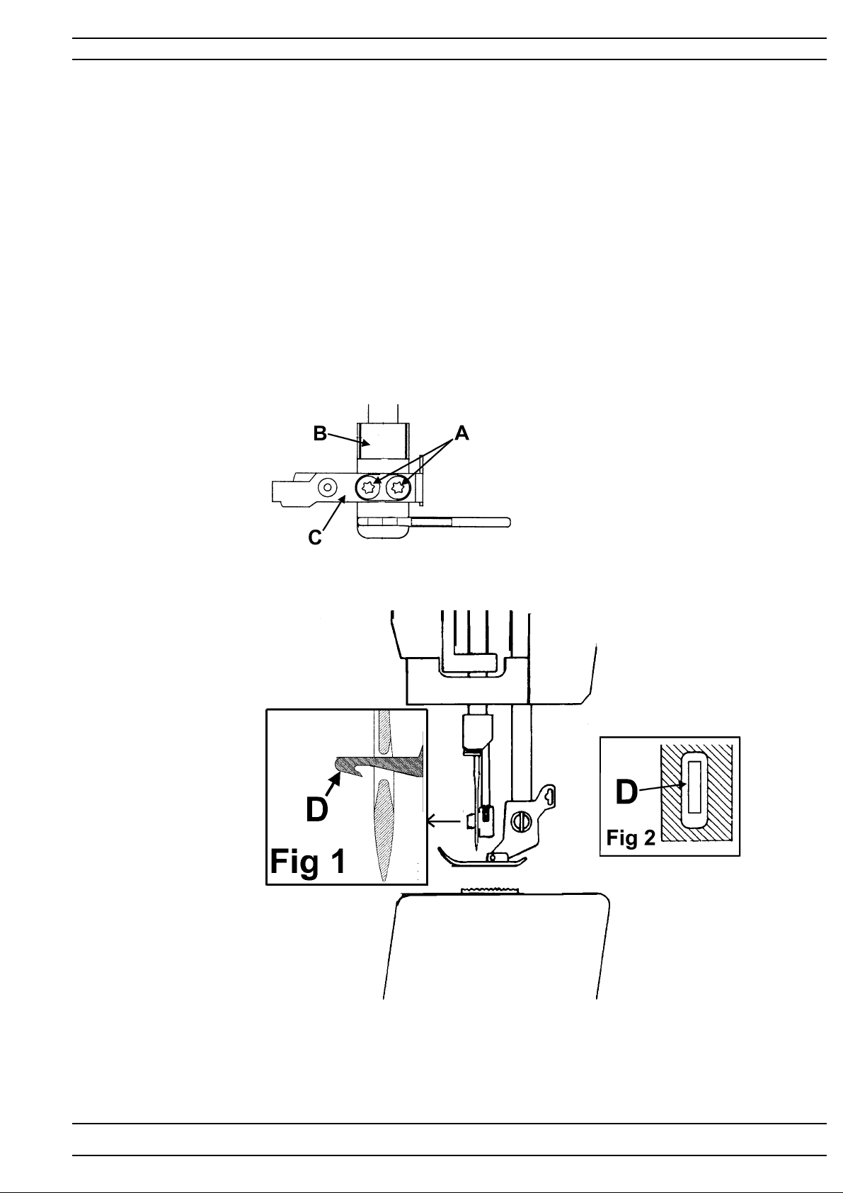
19.Threading device
Check
1. Insert a new needle.
2. Bring the needle to its highest turning position.
3. The threader hook shall go smoothly into the needles eye. See Fig 1 and Fig 2.
Adjustment
1. Loosen the the two screws (A) on the back of the threader head (B).
2. Move the thread head (B) so that the threader hook (D) does not touch
the needle heightways (See fig 1)
3. Move the thread hook holder (C) so that the threader hook (D) does not touch
the needle sideways (See fig 2) .
4. Tighten the screws.
NOTE! Both settings are adjusted at the same time
104 72 53-26
23
Page 24
Settings
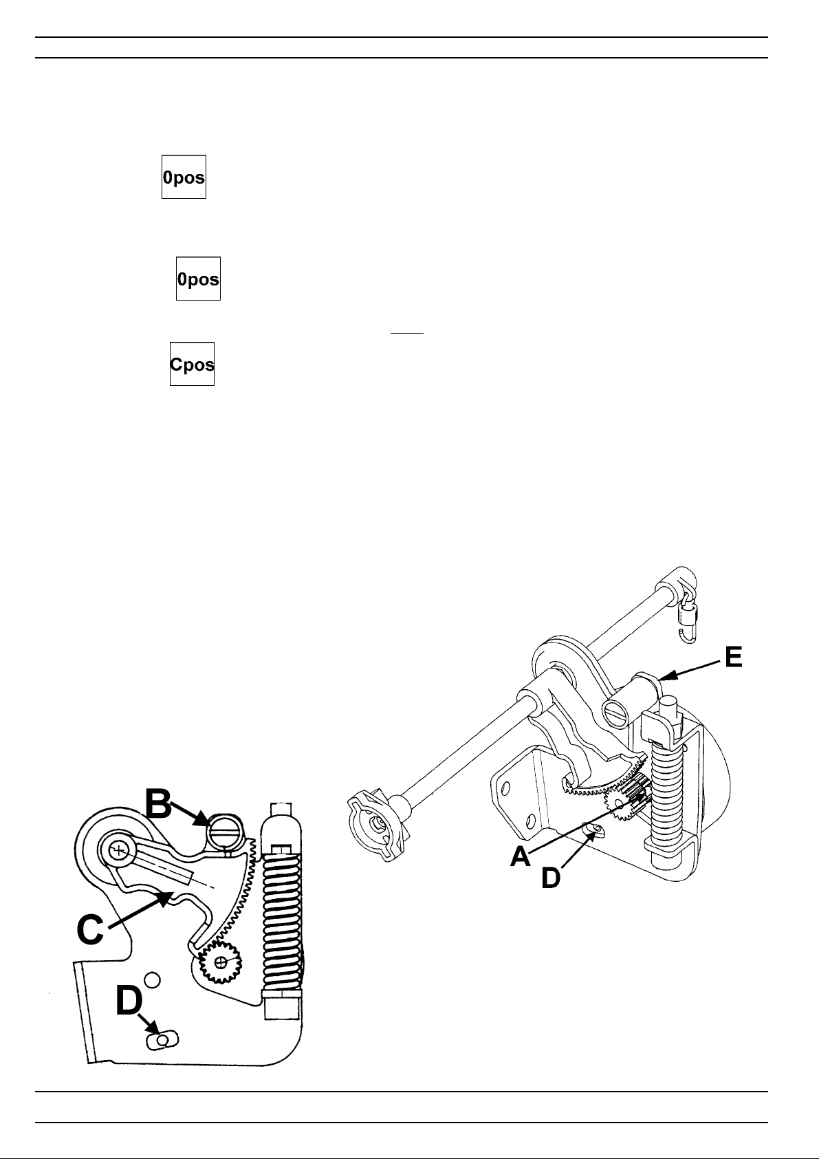
20.Stitch length balance basic setting
Check
Go to the service program.
T ouch Feed- , the feed dog shall now stand still when the foot control is
pressed (0-feeding).
Adjustment
1. T ouch Feed- .Loosen the screw (A) of the cog wheel and turn it until the feed dog comes to a
stand-still when the foot control is pressed.
2. Turn the hand wheel until the needle arrives at its lower turning position.
3.T ouch Feed- .
4. The gap between the segment (C) and the calibration stop (B) should now be Zero (0 mm).
To do adjustment of the distance see "21. Pre-setting of the feeding step motor".
Note! Make sure that distance is equal on both sides of the stop screw (D) before
a basic setting is performed.
24
104 72 53-26
Page 25
Settings
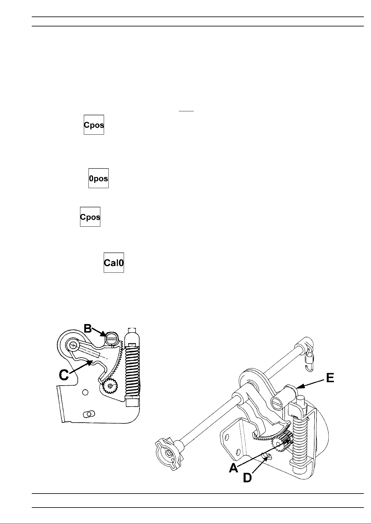
21. Pre-setting the step motor of the feed dog
Check 1
Set the needle in its lower turning position.
The feed dog should after turning the mains switch several times on and off
always reach such a position that 2.5 mm straight stitching will be obtained.
Check 2
Get into the service program.
Turn the hand wheel until the needle arrives at its lower turning position.
Touch Feed-
The gap between the segment (C) and the calibration stop (B) should now
be Zero (0 mm).
Adjustment
1. T ouch Feed- .Loosen the screw (A) of the cog wheel and turn it until the feed dog comes to a
stand-still when the foot control is pressed.
Turn the hand wheel untill the needle arrives at it's lower turning position
T ouch Feed-
Loosen screw (E). Turn the eccentric calibration stop (B) until the gap between segment (C)
and the calibration stop (B) is 0 mm.
Check by first turn the hand wheel until the needle arrives at its lower turning position.
then touch Needle - several times.
The motor should now run smoothly and the gap should remain 0 mm.
104 72 53-26
25
Page 26

Settings
22.Stitch length balance
Check
A Both columns of the buttonhole should be of the same density.
B The machine should sew a motif according to the symbol.
C The mending stitch should look according to the illustration.
(Use the mending stitch in the service menu - touch , row 5 )
Fine adjustment
Touch , row 5 in the service menu 1.
Turn screw (A) until the machine sews a mending stitch according to the illustration.
This adjustment may be done without dismounting the covers (see illustration.).
26
104 72 53-26
Page 27
Settings
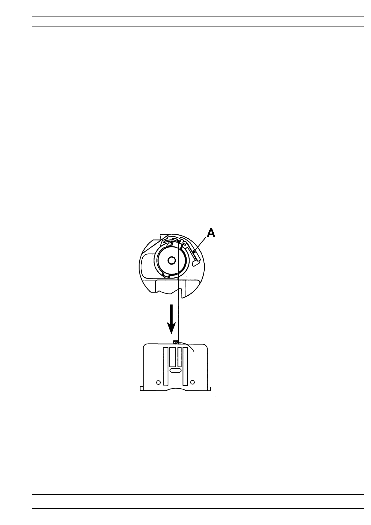
23. Lower thread tension (thread tension of the bobbin case)
Check
1. Insert a full bobbin into the bobbin case.
2. The thread tension spring of the bobbin case shall give a resistance
of 12 - 20 g when pulling the thread slowly .
Adjustment
1. Turn screw (A) until the correct thread tension is obtained.
NOTE ! Before any adjustment is made remove any loose pieces of thread or fluff from
the thread tension discs
104 72 53-26
27
Page 28
Settings
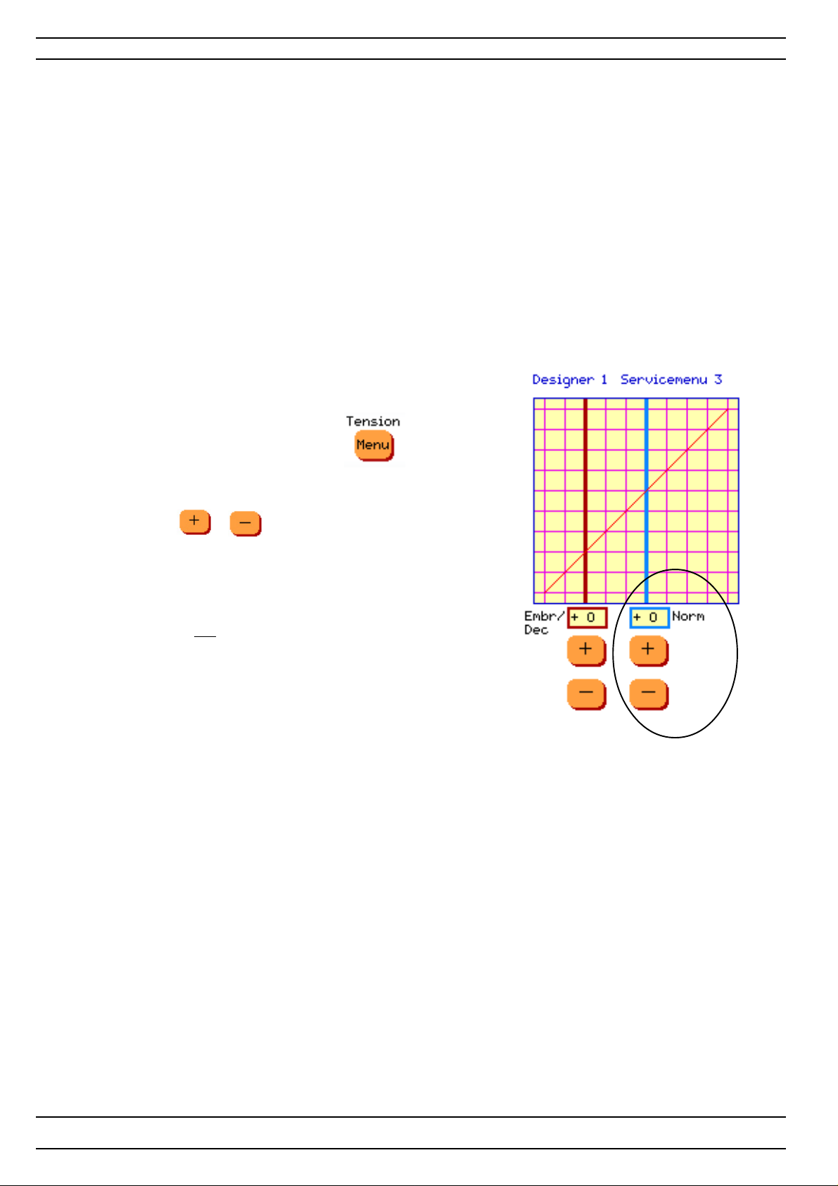
24.Upper thread tension - Position "Norm" - Designer I
Norm is for setting the higher upper thread tension
Check
A correct take-up should be obtained on straight stitch and
zig-zag when the sewing advisor is set on woven medium.
Comment 1
The sewing advisor adjusts the thread tension according to the selection of fabric
and sewing technique.
This is done by means of the computer and the thread tension step motor.
Comment 2
The thread tension that is set in the set menu is to be regarded as a general indication.
This general indication can be raisedand lowered by means of the thread tension buttons
in the Set menu and remains until the machine is turned off.
Adjustment
1. Get into the service program and select .
2. To adjust the HIGHER upper thread tension
e.g on straight stitching or zick-zack sewing use "Norm"
and adjust with or .
3. "Norm" adjustments can be done between -10 and +10
if embroidery thread tension (Embr/Dec) is set on 0 (zero).
If "Embr/Dec" is not set on 0 (zero) there are limitations in
the setting. The value of the setting could be higher or
lower then -10 or +10.
The adjustment is automatically saved.
NOTE ! Before any adjustment is made, remove any loose pieces of thread or fluff from
the thread tension discs.
28
104 72 53-26
Page 29
Settings
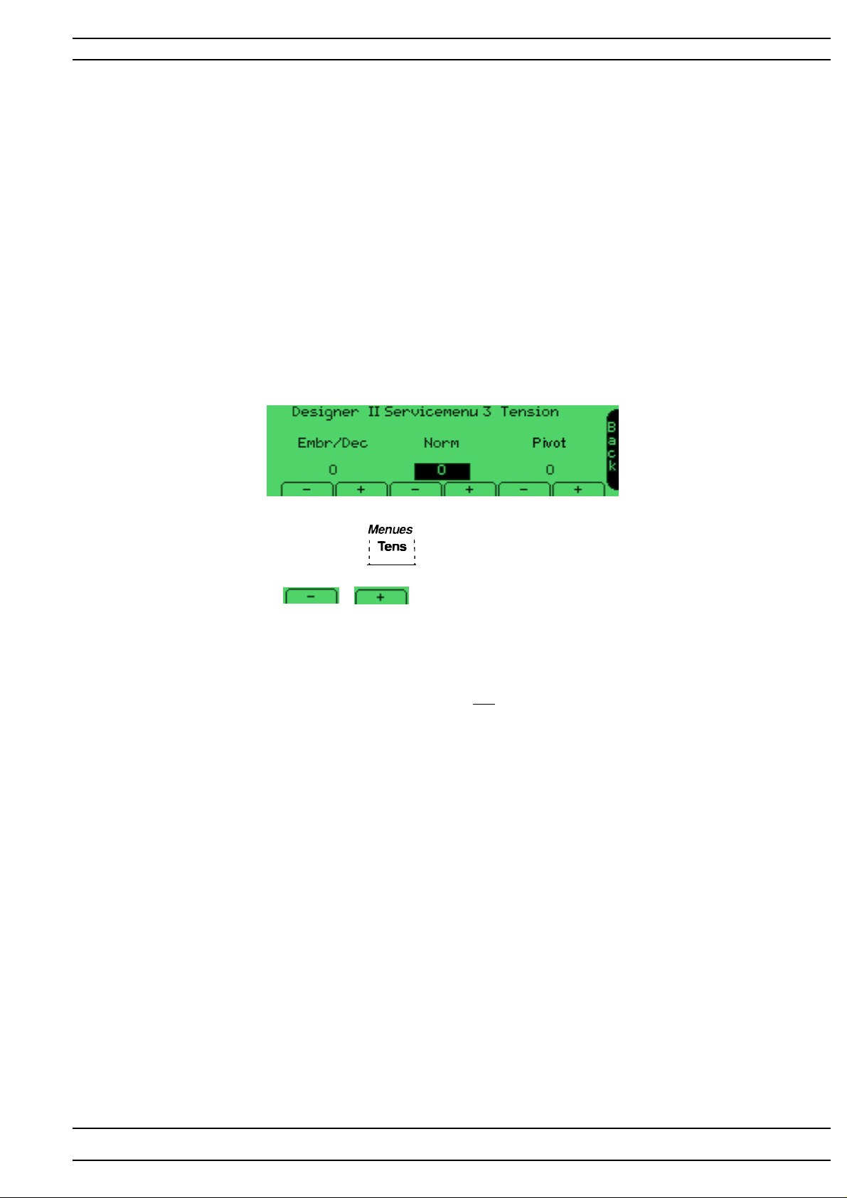
24.Upper thread tension - Position "Norm" Designer II and Quilt Designer
"Norm" is for setting the higher upper thread tension.
Check
A correct take-up should be obtained on straight stitch and
zig-zag when the sewing advisor is set on woven medium.
Comment 1
The sewing advisor adjusts the thread tension according to the selection of fabric
and sewing technique.
This is done by means of the computer and the thread tension step motor.
Comment 2
The thread tension that is set in the set menu is to be regarded as a general indication.
This general indication can be risen and lowered by means of the thread tension buttons
in the Set menu and remains until the machine is turned off.
Adjustment
1. Get into the service program and select .
2. To adjust the HIGHER upper thread tension e.g straight stitching or zick-zack sewing
use "Norm" and adjust with or .
3. "Norm" adjustments can be done between -10 and +10
if embriodery thread tension (Embr) is set on 0 (zero).
If "Embr/Dec" (Designer II), "Decor" (Quilt Designer) is not set on 0 (zero) there are limitations in
the setting. The value of the setting could be higher or
lower then -10 or +10.
The adjustment is automatically saved.
NOTE ! Before any adjustment is made remove any loose pieces of thread or fluff from
the thread tension discs
104 72 53-26
29
Page 30
Settings
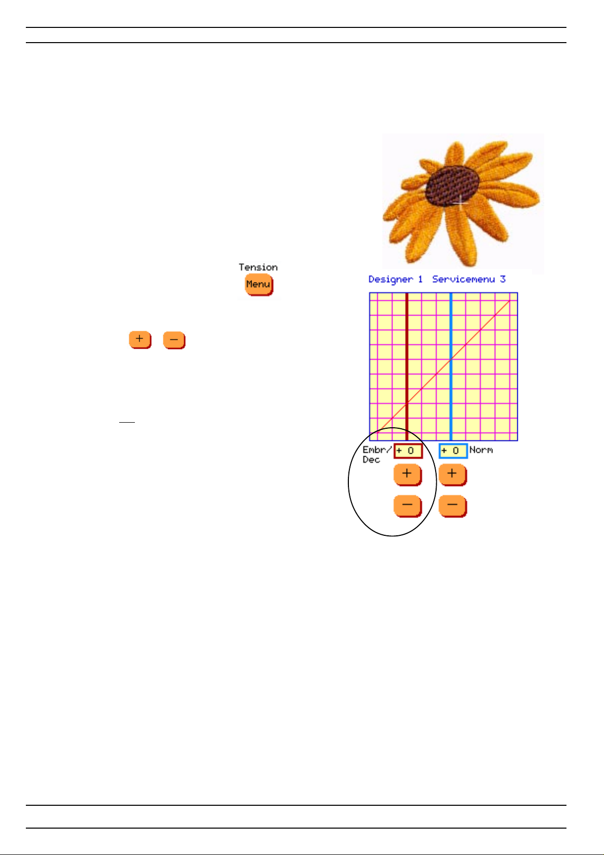
25. Upper thread tension - Position "Embr/Dec" - Designer I
Embr/Dec is for setting the lower upper thread tension.
Check
A correct take-up should be obtained on at embroidery stitch
(e.g.embroidery stitch No 1, menu 4 on Disk 100 Designer 1 Sampler).
Comment
The following embroidery threads shall be used:
Upper thread :Thread thickness No 40 ( e.g. Sulky No 40)
Lower thread: Thread thickness No 70 ( e.g. Sulky bobbin 100)
Adjustment
1. Go to the service program and select .
2. To adjust the LOWER upper thread tension
on the embrodery or decorative sewing use "Embr/Dec"
and adjust with or .
3. "Embr/Dec" adjustments can be done between -10 and +10
if normal thread tension - "Norm" is set on 0 (zero).
If "Norm" is not set on 0 (zero) (e.g +2) there
are limitations in the setting. The value of
the setting could be higher then +10.
The adjustment is automatically saved.
NOTE ! Before any adjustment is made, remove any loose pieces of thread or fluff from
the thread tension discs
30
104 72 53-26
Page 31
Settings
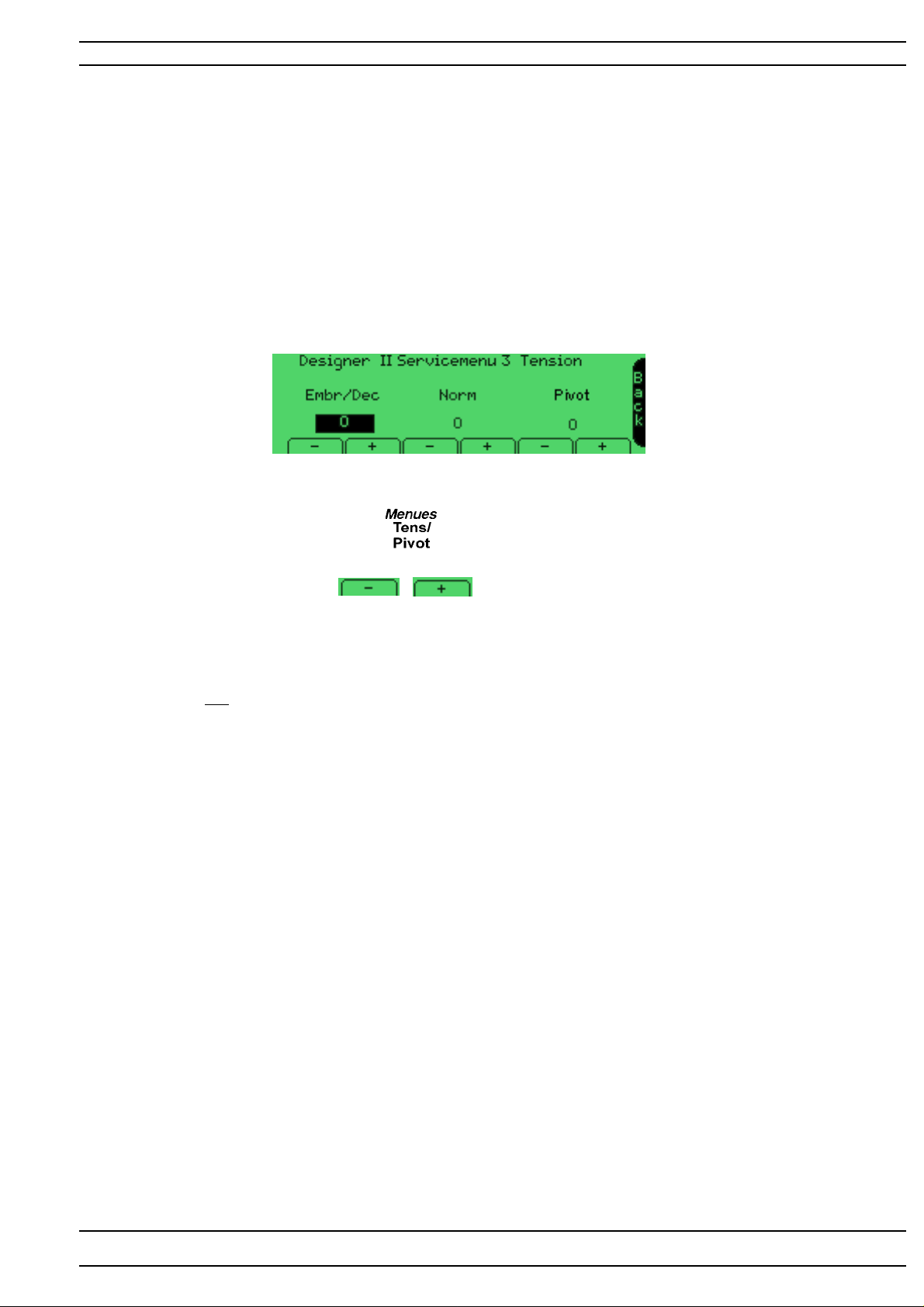
25. Upper thread tension - Position "Embr/Dec" - Designer II
Embr/Dec is for setting the lower upper thread tension.
Check
A correct take-up should be obtained on at embroidery stitch
(e.g.embroidery stitch "Embr 1 " or Embr 2" on the service cassette ).
Comment
The following embroidery threads shall be used:
Upper thread :Thread thickness No 40 ( e.g. Sulky No 40)
Lower thread: Thread thickness No 70 ( e.g. Sulky bobbin 100)
Adjustment
1. Go to the service program and select ..
2. T o adjust the LOWER upper thread tension on the embrodery or decorative sewing
use "Embr/Dec" and adjust with or .
3. "Embr/Dec" adjustments can be done between -10 and +10
if normal thread tension - "Norm" is set on 0 (zero).
If "Norm" is not set on 0 (zero) (e.g +2) there are limitations in the setting. The value of
the setting could be higher then +10.
The adjustment is automatically saved.
NOTE ! Before any adjustment is made, remove any loose pieces of thread or fluff from
the thread tension discs
104 72 53-26
31
Page 32
Settings
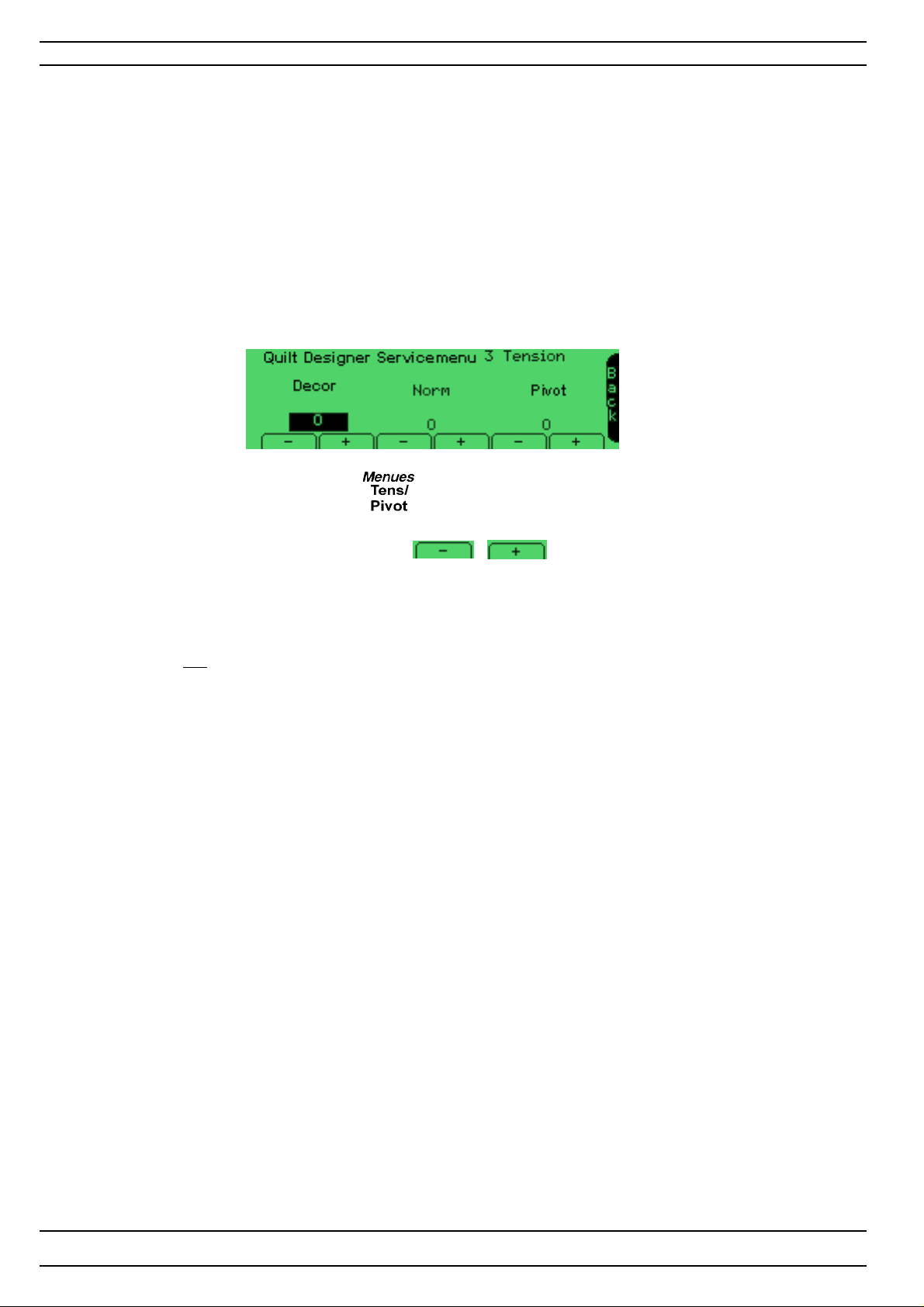
25. Upper thread tension - Position "Decor" - Quilt Designer
"Decor" is for setting the lower upper thread tension.
Check
A correct take-up should be obtained on a stitch that is sewn with the lower upper thread tension,
e.g. a Application stitch or a Decorative stitch .
Adjustment
1. Go to the service program and select ..
2. T o adjust the LOWER upper thread tension on a application or a decorative sewing
use "Decor" - Quilt Designer and adjust with or .
3. "Decor" adjustments can be done between -10 and +10
if normal thread tension - "Norm" is set on 0 (zero).
If "Norm" is not set on 0 (zero) (e.g +2) there are limitations in the setting. The value of
the setting could be higher then +10.
The adjustment is automatically saved.
NOTE ! Before any adjustment is made, remove any loose pieces of thread or fluff from
the thread tension discs
32
104 72 53-26
Page 33
Settings
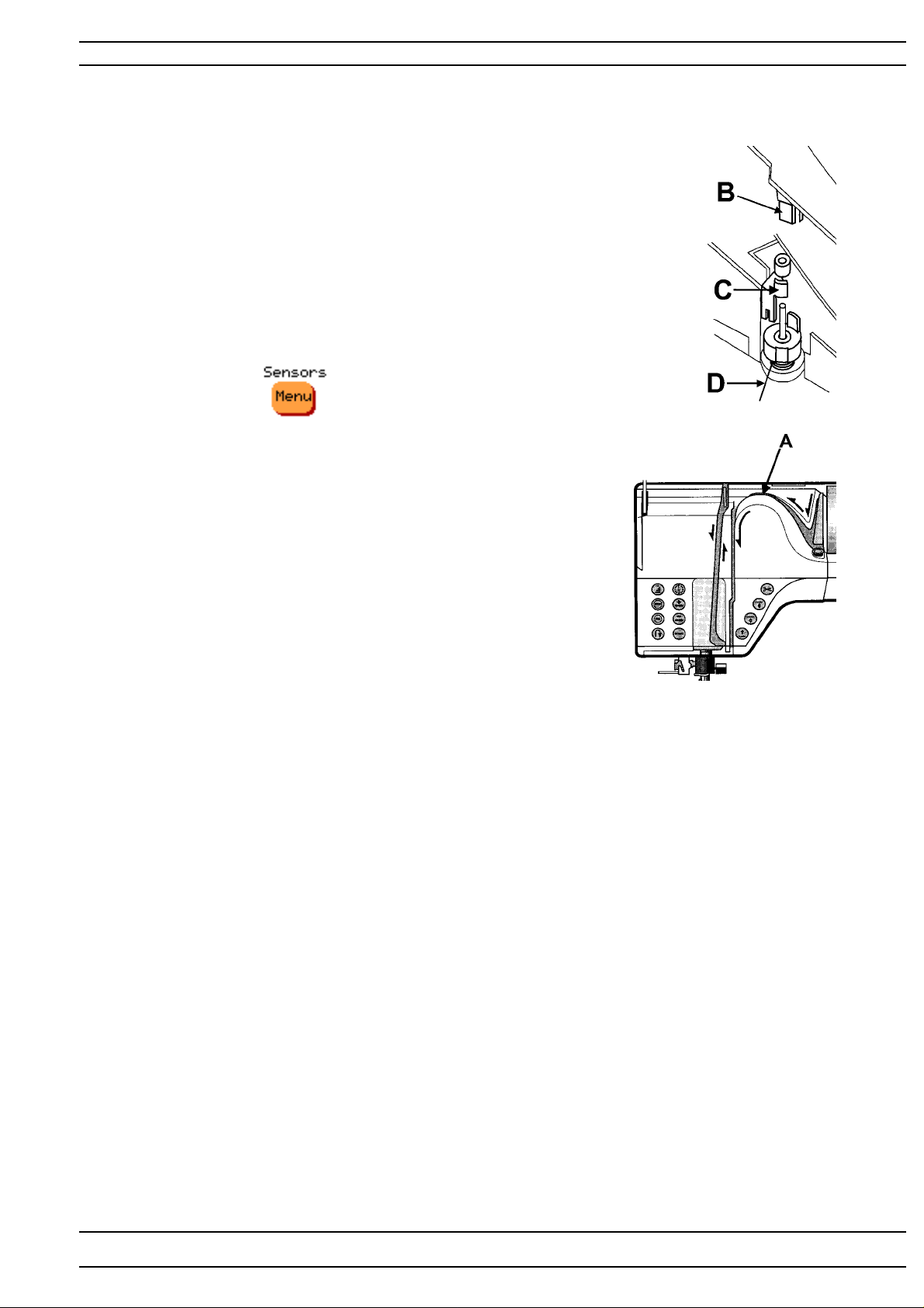
26. Upper thread guard sensor
Check
When the upper thread is finished or breaks the machine will stop.
This is done by means of a photo-diode (B) on the push button board
which reads the movement on the screen (C) which moves
simultaneously with the thread take-up spring (D).
The machine must be threaded in order to activate
the upper thread guard sensor.
Upper thread guard sensor check.
Go to service program.
For Designer I Select in order to check.
For Designer II Select "Menues-Sensor" in order to check.
The function of the upper thread guard sensor is indicated by a square.
Check that the square alternates between filled and not filled when
moving the thread take-up spring.
Dismounting
1. Remove the thread tension cover by taking
a firm grip on the top of the cover (A)
and then carefully pulling it away from the front cover.
2. Remove the push button board by disconnecting
it from the cable .
NOTE ! The setting of the thread take-up spring affects the function of
the upper thread sensor.
104 72 53-26
33
Page 34
Settings
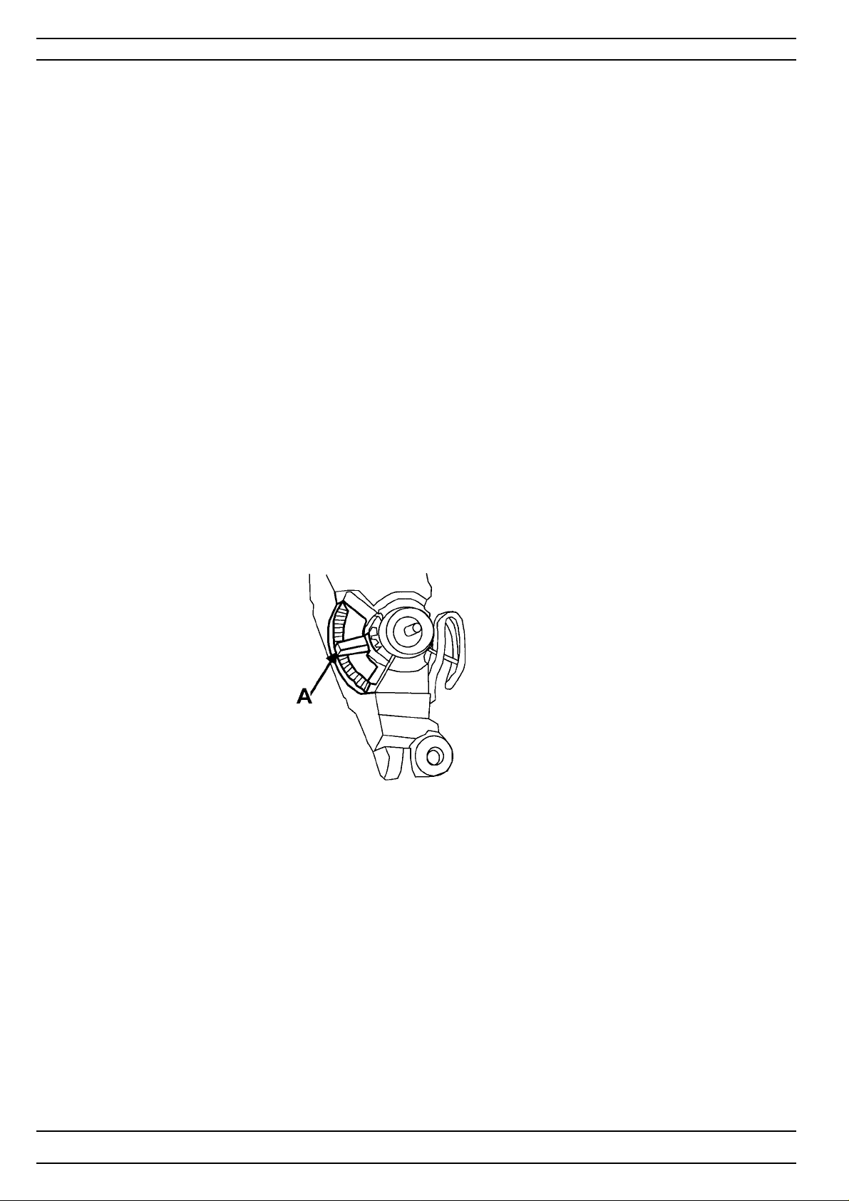
27. Setting the thread take-up spring
Check
The thread take-up spring should have completed its movement when
the needle eye reaches the fabric.
The check has to be carried out in straight stitching in cotton.
Adjustment
1. Remove the thread tension cover by taking a firm grip on the top of the cover
and then carefully pulling it away from the front cover.
2.Turn the thread tension peg (A) with a screw driver until a correct
thread take-up is obtained.
NOTE! The setting of the thread take-up spring affects the function of
the upper thread guard sensor.
34
104 72 53-26
Page 35
Settings
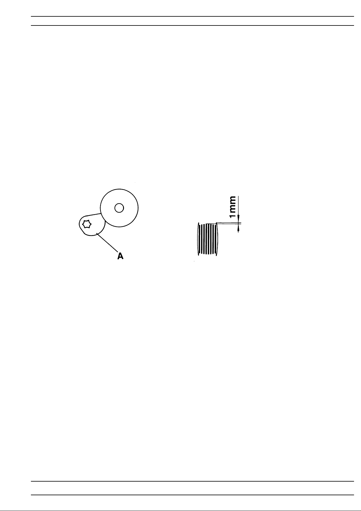
28. Disconnection when winding the bobbin
Check
When winding up the lower thread onto the bobbin the machine should stop
when there is a min. of 1 mm between the edge of the bobbin and the thread.
Adjustment
Turn by means of a screwdriver torx the disconnection (A) until the correct
amount of thread is obtained.
104 72 53-26
35
Page 36
Settings
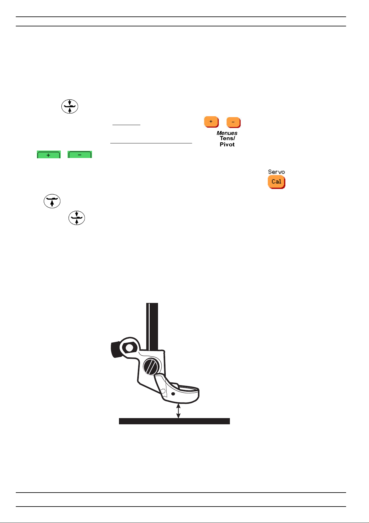
29. Pivot height
Check
When the embroidery pressar foot ”R” is in its ”Pivot” position the distance between the lower side of
Embroidery presser foot ”R” and the stitch plate should be 1,25 mm +/-0,15 mm.
Adjustment
1. Mount the embroidery presser foot ”R” on the machine and lower the feed dog
2. Go to the service program
3. T ouch so the pressar bar takes its ”pivot” position.
4. To adjust the distance on Designer I use the "Pivot" buttons or ,row 3.
To adjust the distance on Designer II and Quilt Designer Touch - and use the "Pivot" buttons
or .
The adjustments can be done between -9 and +9.
To check the adjustment, bring the pressar bar first to it’s highest position by Touch -
or button.
Touch then . so the pressar bar takes its "pivot" position again.
5. Check the distance between the lower side of Embroidery presser foot "R" and the stitch plate
so it's 1,25 mm +/-0,15 mm.
The adjustment is automatically saved when turning off and on the machine
36
1,25 mm +/-0,15 mm
104 72 53-26
Page 37
Service Program - Designer I
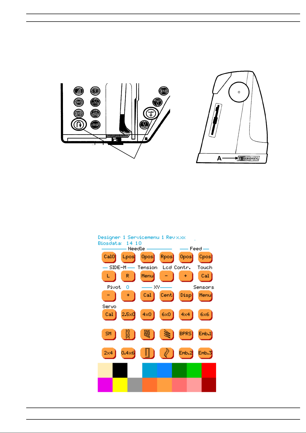
Service program - Designer I
In order to facilitate the checking and setting of the different functions of
the machine there is a service program.
Handling
Go to the service program of the machine by pressing the reverse feed button and
the sensor foot pivot button while the main switch (A) is switched on.
The display will now show the Designer 1 service menu 1. See illustration below.
Press
104 72 53-26
37
Page 38
Service Program - Designer I
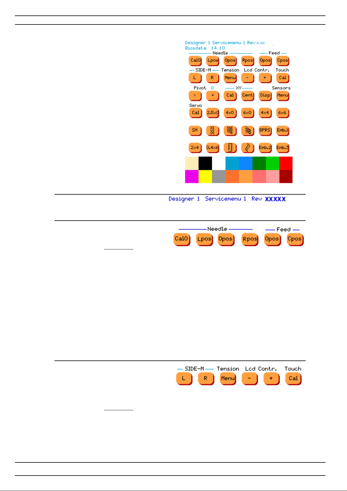
Service program - Designer I
Functions of the service menu 1.
On the top of menu The revision of the program
Service Menu 1
Row 1
Toucharea
Needle/Feed Cal 0 Upper needle position - Checking the centre position of the needle
step motor.
Lower needle position - Checking the centre position of the feeding
step motor.
Needle Lpos Is used for pre-setting the step motor of the needle.
The step motor of the needle now takes its left calibration position.
Needle Opos Is used when setting the centre position of the needle.
The step motor of the needle is now in its centre position.
Needle Rpos Is used for pre-setting the stepmotor of the needle.
The step motor of the needle now takes its right calibration position.
Feed 0 pos Is used when coarse-adjusting the stitch length balance
The feed dog should now stand still ( 0-feeding).
Feed C pos Is used when pre-setting the feeding step motor .
The step motor now takes its calibration position.
Service Menu 1
Row 2
T oucharea
Side motion L Left position.
Side motion R Right position.
T ension Menu Setting of the thread tension. (The machine will enter Service
Menu 3)
LCD Contrast + The contrast of screen.
LCD Contrast - The contrast of screen.
T ouch Cal Calibration of the touch display .
38
104 72 53-26
Page 39
Service Program - Designer I
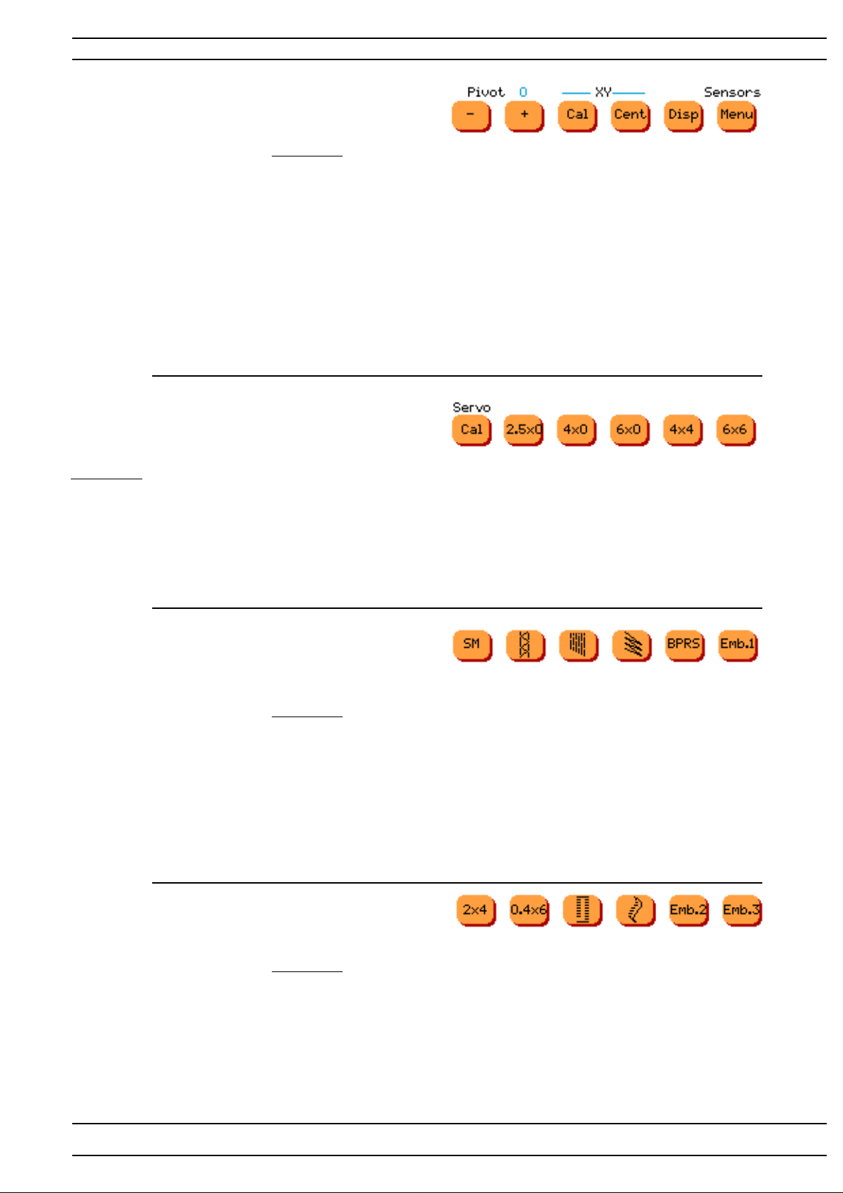
Service Menu 1
Row 3
Toucharea
Pivot-sewing head - Sewing heads Pivot minus function
Pivot- sewing head + Sewing heads Pivot plus function
Embroidery Unit Ca l Is used to check the sideways and lengthwise
movement of the embroidery unit.
Embroidery Unit Cent The embroidery hoop sensor arm takes its centre position.
Disp Display test. A square pattern shall change between
blue, red and green. Af ter the check is done the machine
will automatically enter the service menu 1 again.
Sensors Menu Sensor check. (The machine enters Service Menu 2).
Service Menu 1
Row 4
Toucharea
Servo Ca l Sewing head - Presser bar takes its highest position.
2,5x0 The machine sews straight stitch 2,5 mm.
4.0x0 The machine sews straight stitch 4 mm.
6,0x0 The machine sews straight stitch 6 mm.
4x4 The machine sews a zig zag stitch 4x4 mm.
6x6 The machine sews a zig zag stitch 6x6 mm.
Service Menu 1 1 2 3 4 5 6
Row 5 T oucharea
1 = SM The machine sews a side motion stitch.
2 =
3 = Is used for fine-adjusting the stitch length balance.
The machine now sews a pre-programed mending stitch.
4 =
5 = BPRS The machine sews signs B,P,R,S.
6 = Embr 1 The machine sews the first embroidery on an inserted
Embroidery disk.
Service Menu 1 1 2 3 4 5 6
Row 6 T oucharea
1 = 2x4 The machine sews a zig zag stitch 2x4 mm.
2 = 0,4x6 The machine sews a zig zag stitch 0,4x6 mm.
3 =
4 =
5 = Embr 2 The machine sews the second embroidery on an inserted
Embroidery disk.
6 = Embr 3 The machine sews the first embroidery on an inserted
Embroidery disk.
104 72 53-26
39
Page 40
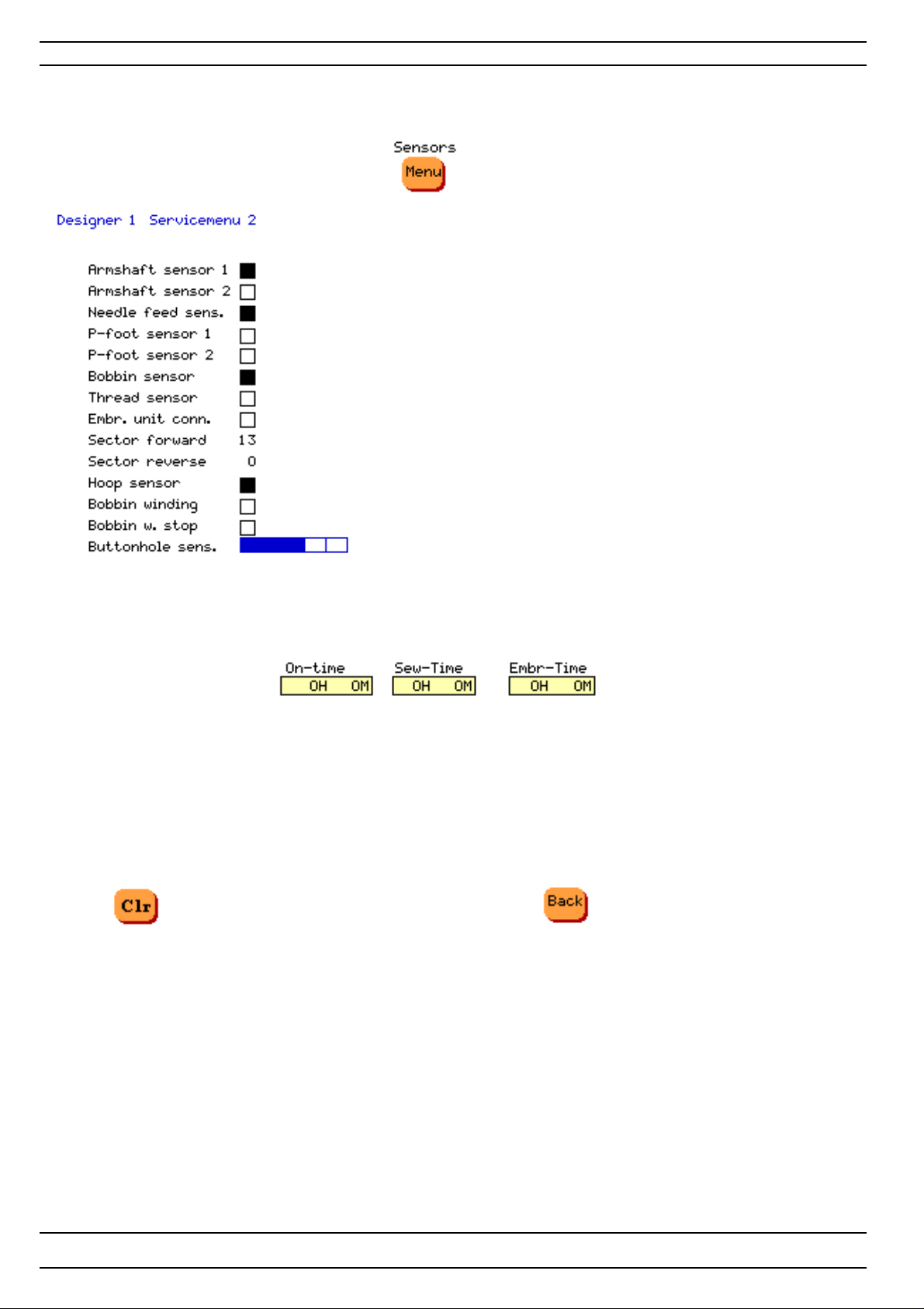
Service Program - Designer I
Functions of the service menu 2 - Designer I -Sensor check
Operation
Get into the service program, touch Sensor- on Row 3
Active square is filled
Check of armshaft's first sensor (stop right function)
Check of armshaft's second sensor (stop right function)
Check of needle
Check of presserfoot's first sensor
Check of presserfoot's second sensor
Check of lower thread guard indicator
Check of upper thread guard indicator
Check if embroidery unit is connected
Embroidery hoop sensor- Indicates when sensor is on calibration mark
The bobbin winding sensor
The bobbin winding sensor -Indicates when bobbin is wounded.
Button hole sensor check
On-Time Indicates how many hours and minutes the machine has been
switched on.
Sew-Time Indicates how many hours and minutes the machine has been
sewed on.
Embr-Time Indicates how many hours and minutes the machine has been
embroidered on.
Clr- Used to erase everything programed in the
programmable memories ot the machine
Back to service menu 1
40
104 72 53-26
Page 41
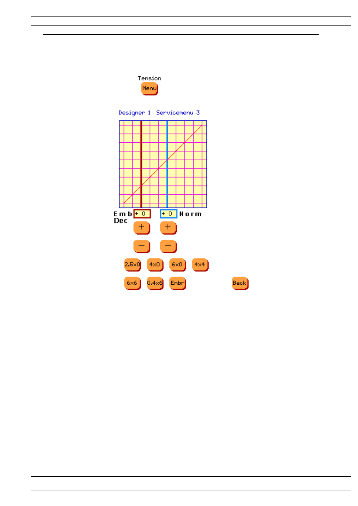
Service Program - Designer I
Functions of the service menu 3 - Designer I - Upper thread tension
T o facilit ate the setting of the upper thread tension there is an electronic adjustment
in the Service menu 3.
Operation
Get into the service program.T ouch , row 2. The machine will enter Service Menu 3.
T ension Norm -Blue
Is used for adjustment of the HIGHER upper thread tension at normal sewing .
The value is normally set between +10 and -10. The value on the display is changed gradually each time
you touch the touch area.
Note! There are limitations in the setting. The value of the setting could be higher then +10 or
lower then -10 .
T ension Embr/Dec- Red
Is used for adjustment of the LOWER upper thread tension at embroidery and decorative sewing.The value
is normally set between +10 and -10.
The value on the display is changed gradually each time you touch the touch area
Note! There are limitations in the setting. The value of the setting could be higher +10.
104 72 53-26
41
Page 42
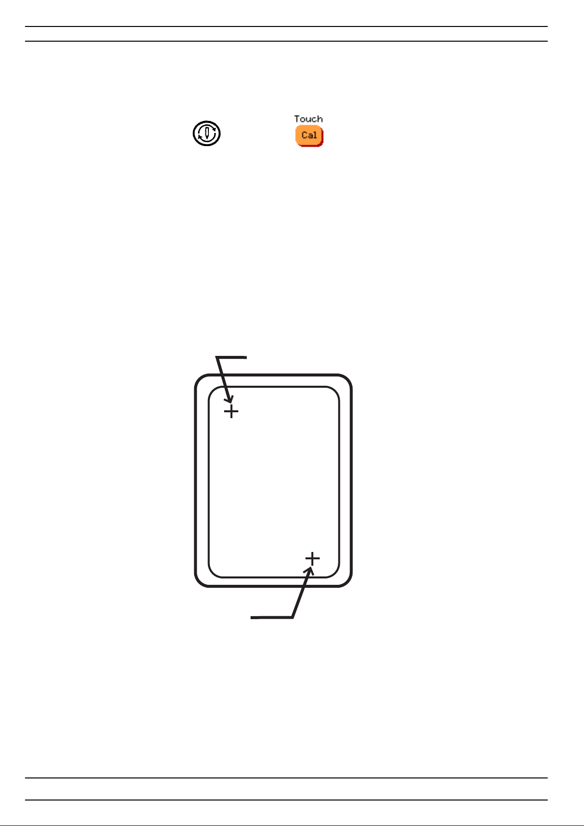
Service Program - Designer I
Calibration of the touch panel - Designer I
How to synchronize the touch area of the touch panel with the symbols on the screen.
Go to the service program of the machine.
Press the needle stop button or touch Touch ,row 2 in the service menu 1.
1. Touch with a blunt object in the center of cross 1, indicated First calibration mark
on the illustration. When the colour changes from black to green the first calibration of
the touch panel is set.
2. Touch with a blunt object in the center of cross 2, indicated Second calibration mark
on the illustration. When the second and final calibration of the touch panel is set the machine will now
automatically enter the service menu 1.
Second calibration mark
First calibration mark
Set the calibration of the touch panel with gauge 412 22 33-01
NOTE! If a touch panel is replaced the new must always be re-calibrated.
42
104 72 53-26
Page 43
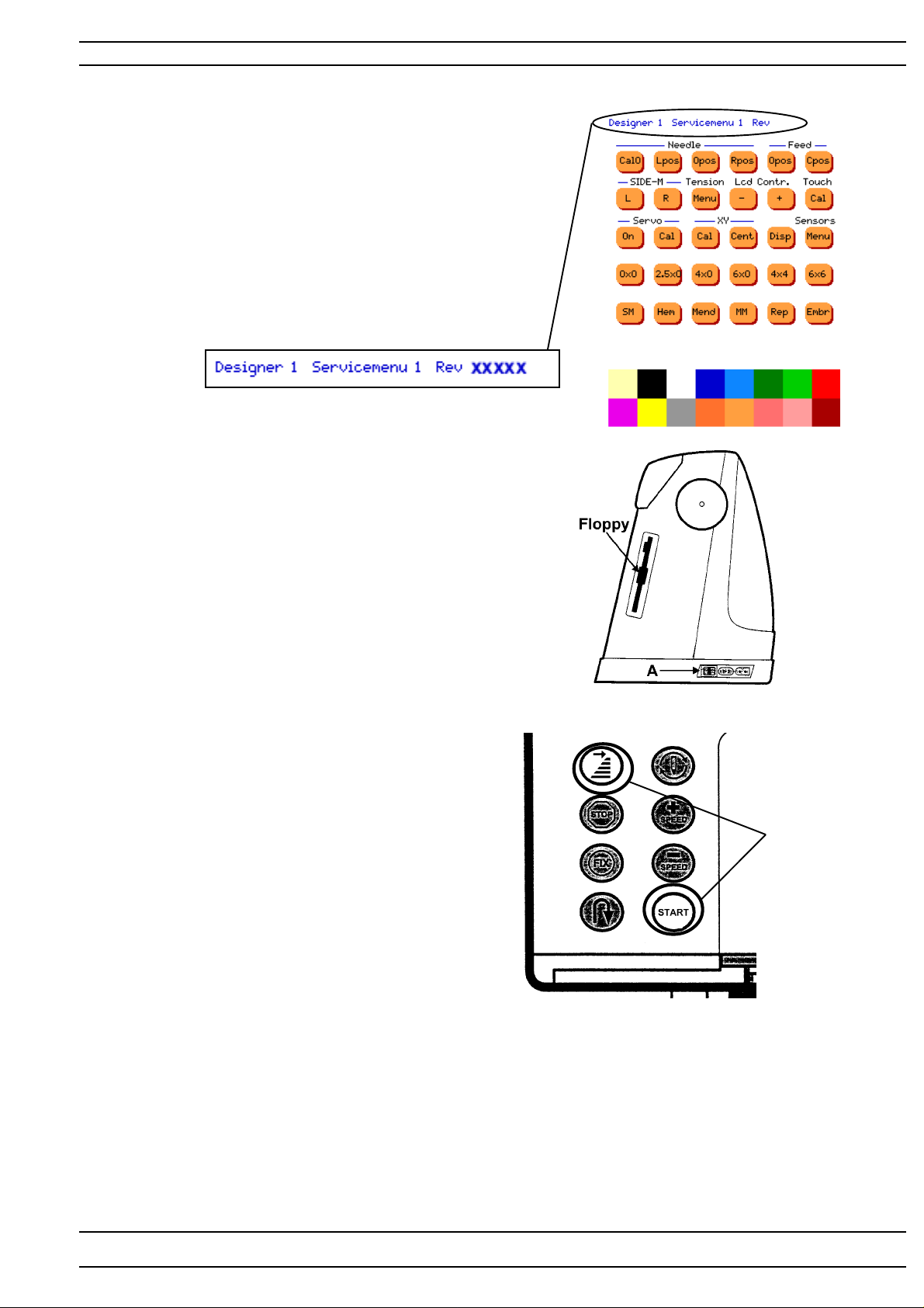
Service Program - Designer I
Update of the memory - Designer I
The Designer I has a memory in which the characteristics
and stitches of the machine are stored.
In order to update the memory the machine has an
update mode.
The program memory on Designer I is updated through
a floppy disc.
Revision of the program
The revision of the program can be seen in
the lower right side of welcome screen or
checked in the service program menu 1
How to update
1. Insert the disk with the new memory
information in the floppy disk drive.
2. Go to the update mode of the machine
by pressing the start/stop button
and the stitch re-start button as
the main switch (A) is turned on.
3. The memory will now automatically
be updated.
Press
4. When the memory of the machine is correctly updated REST A RT is indicated on the
screen. Then...
-Turn off the machine.
-Remove the Floppy disk.
5. Re-start the machine and check the revision (see above).
NOTE! If the Main PC board is changed the memory always has to be updated with the latest
version.
104 72 53-26
43
Page 44
Service Program- Designer II
Service program Designer II
In order to facilitate the checking and setting of the different functions of
the machine there is a service program that is used together with the Designer II service casette.
Press
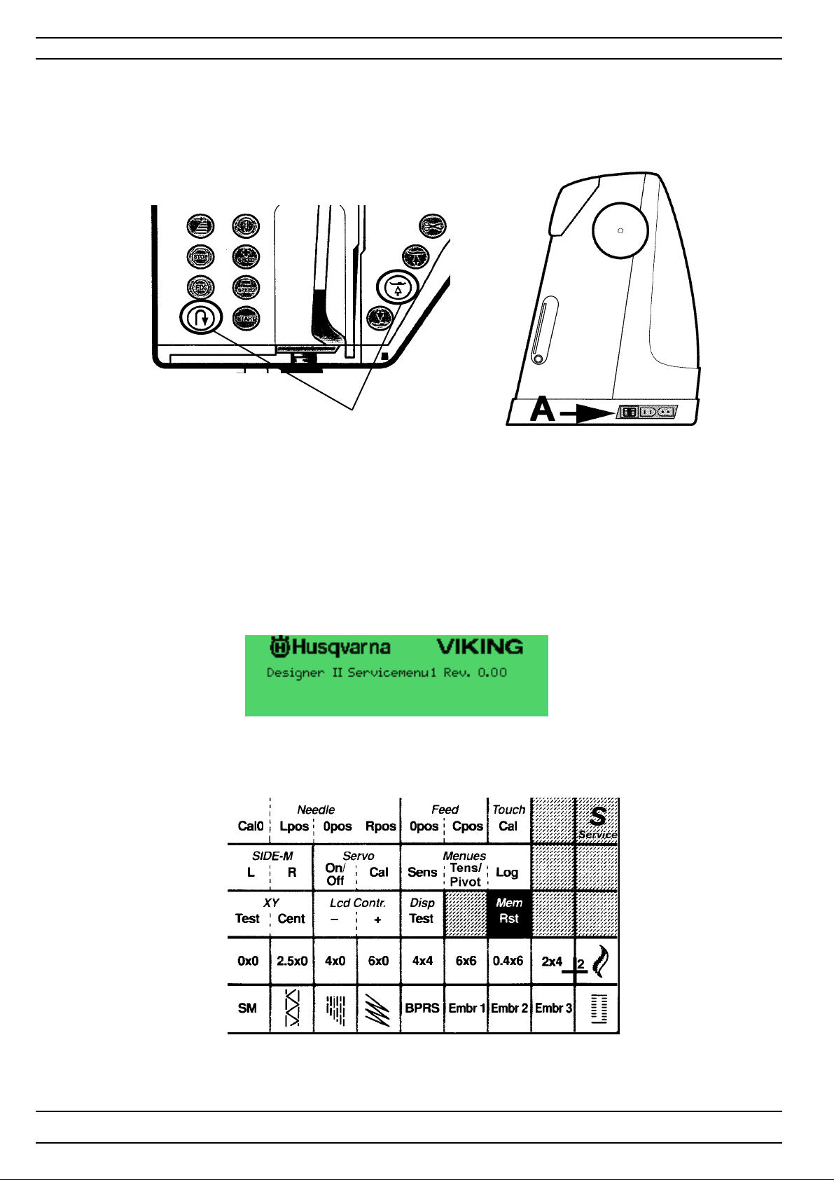
Handling
Insert the Designer II service card in the machine and go to the service program of the machine by
pressing the reverse feed button and the sensor foot pivot button as the main switch (A) is
switched on.
The display will show the Designer II service meny 1, See illustration below.
44
104 72 53-26
Page 45
Service Program - Designer II
Service program - Designer II
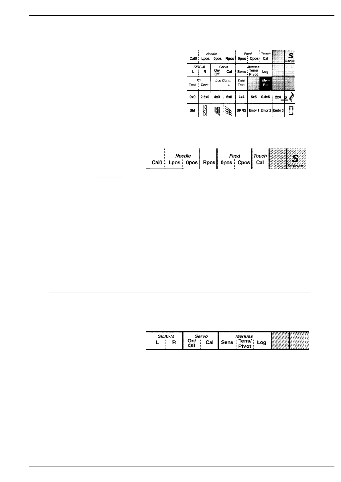
Functions of the service menu 1.
Service cassette
Row 1
Toucharea
Needle Cal 0 Upper needle position - Checking the centre position of the needle step
motor.
Lower needle position - Checking the centre position of the feeding
step motor.
Needle Lpos Is used for pre-setting the needle stepmotor .
The needle stepmotor of the needle now takes its left calibration
position.
Needle Opos Is used when setting the centre position of the needle.
The step motor of the needle is now in its centre position.
Needle Rpos Is used for pre-setting the needle stepmotor.
The step motor of the needle now takes its right calibration position.
Feed 0 pos Is used when coarse-adjusting the stitch length balance
The feed dog should now stand still ( 0-feeding).
Feed C pos Is used when pre-setting the feeding step motor .
The step motor now takes its calibration position.
Service cassette
Row 2
Toucharea
SIDE-M L Side motion - Left position
R Side motion - Right position
Servo
On/off Sewing head - Pivot function ON / OFF.
Ca l Sewing head takes its calibration position.
Menues
Sens To Service menu 2 - Sensor check
T ens/Pivot T o Service menu 3
-Setting the upper thread tension
-Setting the height of the Sewing heads pivot function.
Lo g T o Service menu 4 - Time function of the machine
broidered on.
104 72 53-26
de motion L Left position.
45
Page 46
Service Program - Designer II
Service cassette
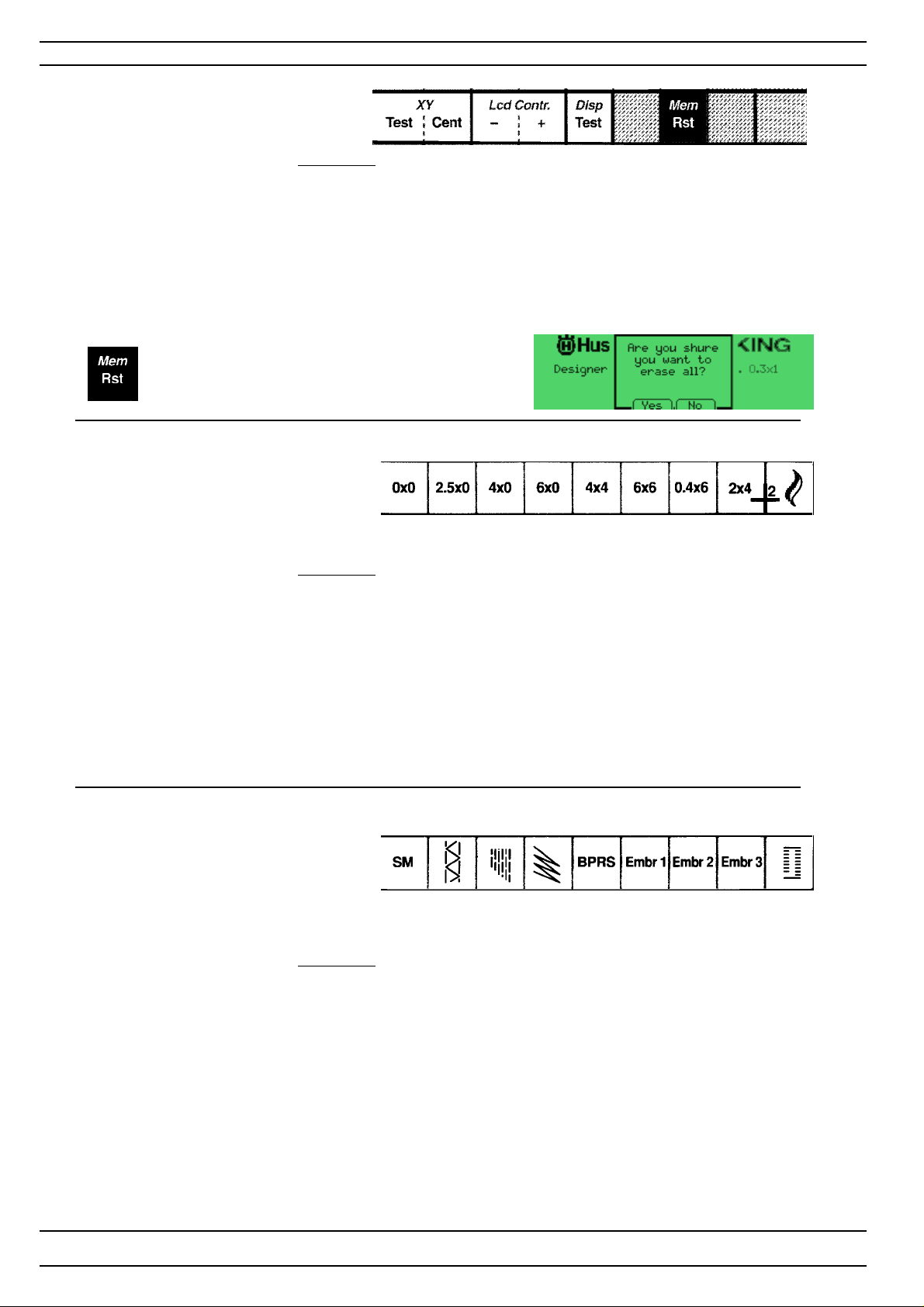
Row 3
Toucharea
X - Y T e st Is used to check the sideways and lengthwise movement
of the embroidery unit.
X- Y Cent The embroidery hoop sensor arm takes its centre position.
Lcd-Contr + Increases the light in the LCD
Lcd-Contr - Decreases the light in the LCD
Display test. Disp The Display shall change between 4 different squared pattern,
after the check is done the machine will go back to the latest
choosen menu or Service menu.
Mem / Rst is used to erase everything
programed in the programmable
memories ot the machine
Service cassette
Row 4
Service cassette
Row 5
1 2 3 4 5 6 7 8 9
Toucharea
1 0x0 Is used when coarse-adjusting the stitch length balance
The feed dog should now stand still ( 0-feeding).
2 2,5x0 The machine sews straight stitch 2,5 mm.
3 4.0x0 The machine sews straight stitch 4 mm.
4 6,0x0 The machine sews straight stitch 6 mm.
5 4x4 The machine sews a zig zag stitch 4x4 mm.
6 6x6 The machine sews a zig zag stitch 6x6 mm.
7 0,4x6 The machine sews a zig zag stitch 0,4x6mm
8 2x4 The machine sews a zig zag stitch 6x6 mm
9 --- ---
1 2 3 4 5 6 7 8 9
Toucharea
1 SM The machine sews a side motion stitch.
2 Hem
3 Mend Is used for fine-adjusting the stitch length balance.
The machine now sews a pre-programed mending stitch.
4MM
5 Rep The machine sews signs B,P ,R,S.
6 Embr 1 The machine sews the first embroidery on the inserted
Service d-Card.
7 Embr 2 The machine sews the second embroidery on the inserted
Service d-Card
8 Embr 3 The machine sews the third embroidery on the inserted
Service d-Card
9 ------
46
104 72 53-26
Page 47
Service Program - Designer II
Function of the Service menu 1
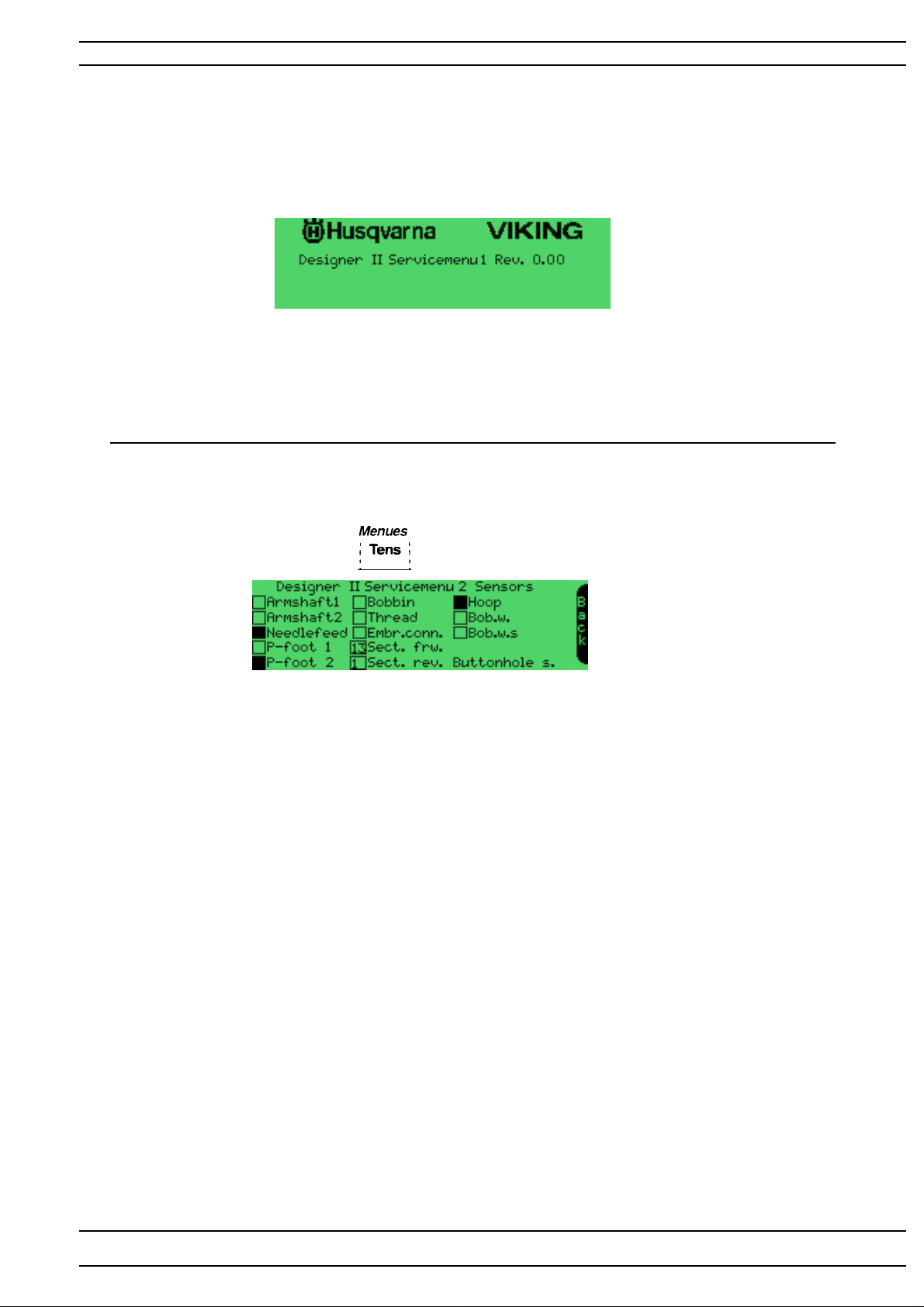
The revision of the program memory
Functions of the service menu 2 - Designer II
Sensor check -
Operation
Get into the service program, touch on Row 2
Active square is filled
Armshaft1 Check of armshaft's first sensor (stop right function)
Armshaft2 Check of armshaft's second sensor (stop right function)
Needlefeed Check of needle
P-foot 1 Check of presserfoot's first sensor
P-foot 2 Check of presserfoot's second sensor
Bobbin Check of lower thread guard indicator
Thread Check of upper thread guard indicator
Embr.conn. Check if embroidery unit is connected
Sect.frw
Sect.rev
Hoop Embroidery hoop sensor- Indicates when sensor is on calibration mark
Bob.w. The bobbin winding sensor
Bob.w.s. The bobbin winding sensor -Indicates when bobbin is wounded.
Buttonhole s. Button hole sensor check
Back Back to service menu 1
104 72 53-26
47
Page 48
Service Program - Designer II
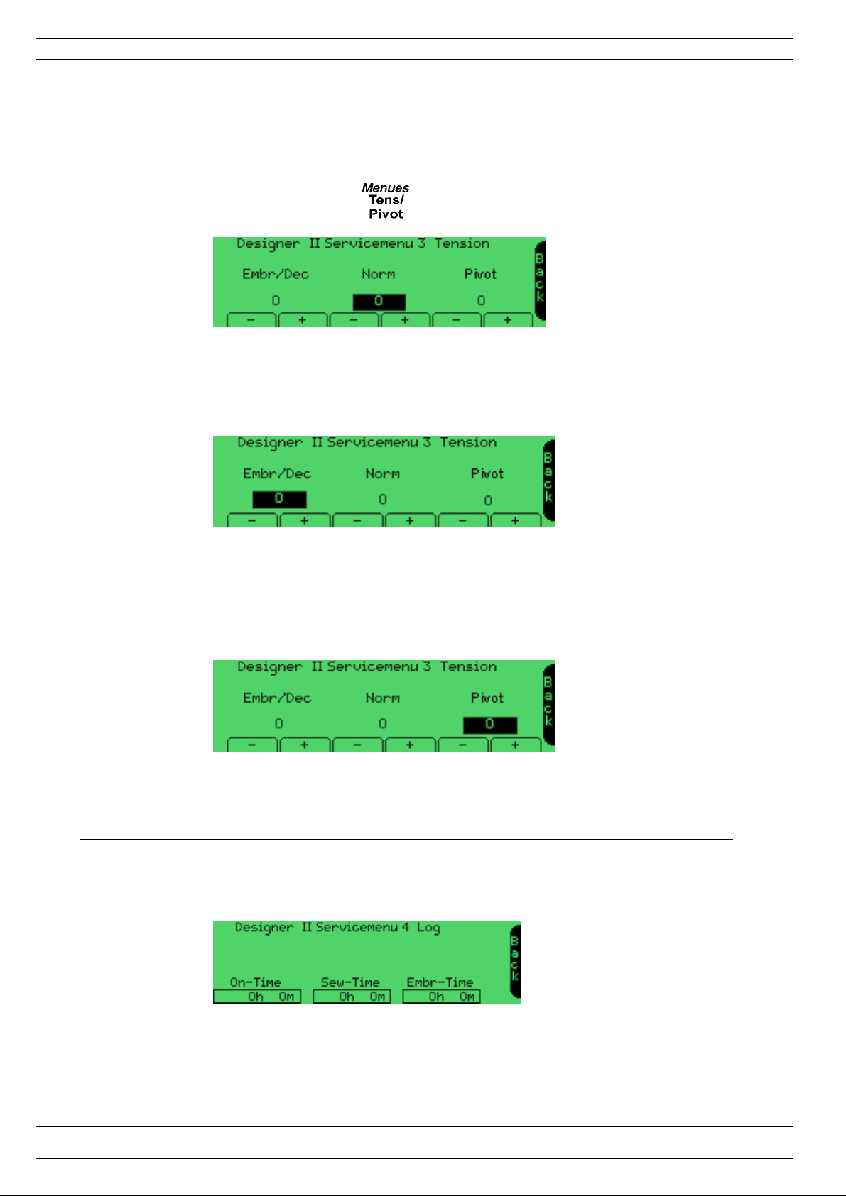
Functions of the service menu 3 - Designer II.
Upper thread tension and Pivot position
T o facilit ate the setting of the upper thread tension there is an electronic adjustment
in the Service menu 3.
Operation
Get into the service program. Touch Menues row 2. The machine will enter Service Menu 3.
T ension Norm
Is used for adjustment of the HIGHER upper thread tension at normal sewing . The value is normally set
between +10 and -10. The value on the display is changed gradually each time you touch the touch area.
Note! There are limitations in the setting. The value of the setting could be higher then +10 or
lower then -10 .
T ension Embr/Dec
Is used for adjustment of the LOWER upper thread tension at embroidery and decorative sewing.The value
is normally set between +10 and -10.
The value on the display is changed gradually each time you touch the touch area
Note! There are limitations in the setting. The value of the setting could be higher +10.
Pivot
Is used for adjustment of the presser bars pivot position. The value is normally set between +9 and -9.
The value on the display is changed gradually each time the touch area is touched
NOTE! the pressarbar must be re-calibrated before the setting has any affect.
Functions of the Service Menu 4 - Designer II
Log menu
48
On time Indicates how many hours and minutes the machine has been on
Sew-Time Indicates how many hours and minutes the machine has been sewed on
Embr-time Indicates how many hours and minutes the machine has been embroidered on
104 72 53-26
Page 49
Service Program - Designer II
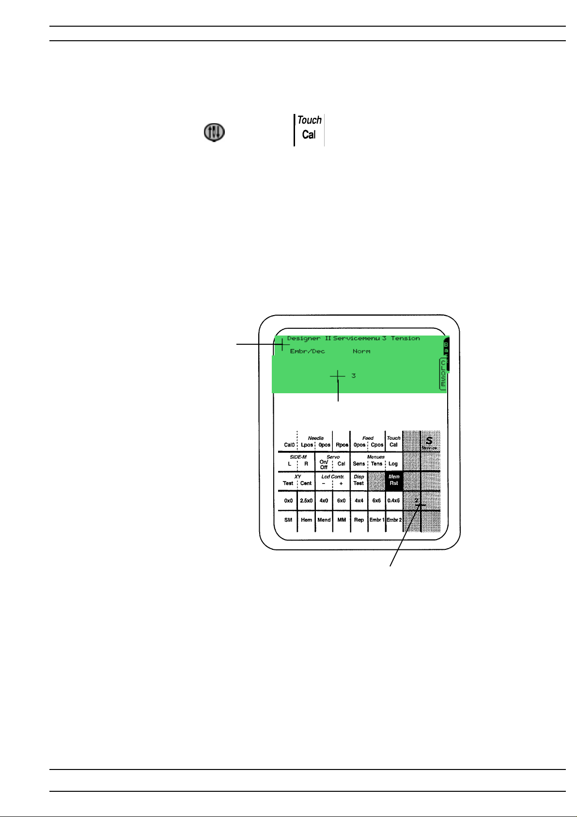
Calibration of the touch panel - Designer II
How to synchronize the touch area of the touch panel with the symbols on the screen.
Get into the service program of the machine.
Press the needle stop button or touch T ouch ,row 1 on the service card.
1. Touch with a blunt object in the center of cross 1 so that it disapeares. Indicated as the First
calibration mark on the illustration.
2. Touch with a blunt object in the center of cross 2, indicated Second calibration mark
on the illustration.NOTE ! The second calibration mark is the red cross on the Service card.
3. Touch the 3rd cross and the machine will return to Service menu or the menu that was open before the
Calibration is done . NOTE! The Third calibration mark will only appear in the display when the
second calibration mark is calibrated.
First calibration mark
Third calibration mark
Second calibration mark
Set the calibration of the touch panel with gauge 412 22 33-01
104 72 53-26
49
Page 50
Service Program- Designer II
Update of the memory - Designer II (Read & write unit)
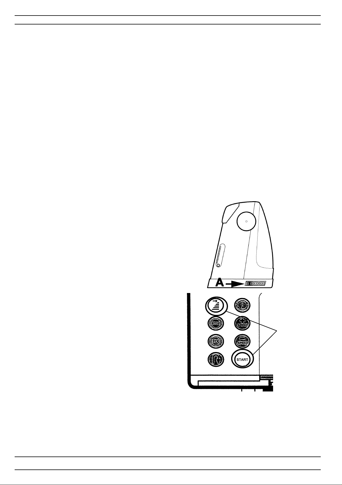
The Designer II has a memory in which the characteristics and stitches of the machine are stored.
In order to update the memory the machine has an update mode.
The program memory on Designer II is updated through the Programmable d-Card.
Revision of the program
The revision of the program can be seen in the middle of the welcome screen or checked in the service
program menu 1.
How to transfer the Designer II program memory to a programmable d-Card
A d-Card reader/writer is needed to transfer the program memory to programable d-card.
The latest version of the Designer II program memory can be found on Husqvarna Vikings Internet page.
NOTE! All data that is stored on the programmable d-Card will be erased when the Designer II
program memory is transfered to the programmable d-Card.
Make sure that the d-card reader/writer is properly connected to the computer before starting the download.
1. Insert a programmable d-Card in the d-Card reader/writer unit.
2. Go to the Husqvarna Viking update page on the Internet. Click on the Designer II update icon.
3. A update program will start. Follow the instructions in the program.
4. Remove the Programmable d-Card when the update files are transfered to it.
How to update the machine
1. Insert the programmable d-card with the new memory
information in the d-card reader in the machine.
2. Get into the update mode of the machine
by pressing the start/stop button
and the stitch re-start button while
the main switch (A) is turned on.
3. The memory will now automatically
be updated.
4. When the memory of the machine is correctly
updated REST ART is indicated on the screen.
Then...
-Turn off the machine.
-Remove the d-card.
Press
5. Re-start the machine and check the revision (see above).
NOTE! If the Main PC board is changed the memory always has to be updated with the latest
version.
50
104 72 53-26
Page 51
Service Program- Quilt Designer
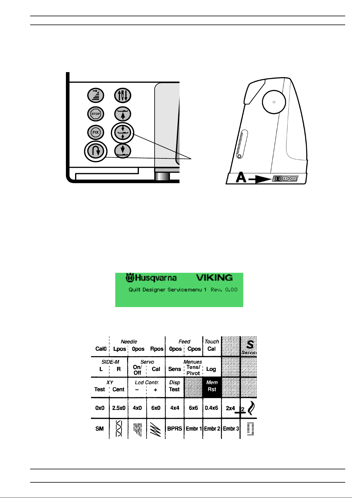
Service program for Quilt Designer
In order to facilitate the checking and setting of the different functions of
the machine there is a service program that is used together with the service d-card.
Press
Handling
Insert the service d-Card in the machine and go to the service program of the machine by pressing the
reverse feed button and the sensor foot pivot button as the main switch (A) is switched on.
The display will show the Quilt Designer service meny 1, See illustration below.
104 72 53-26
51
Page 52
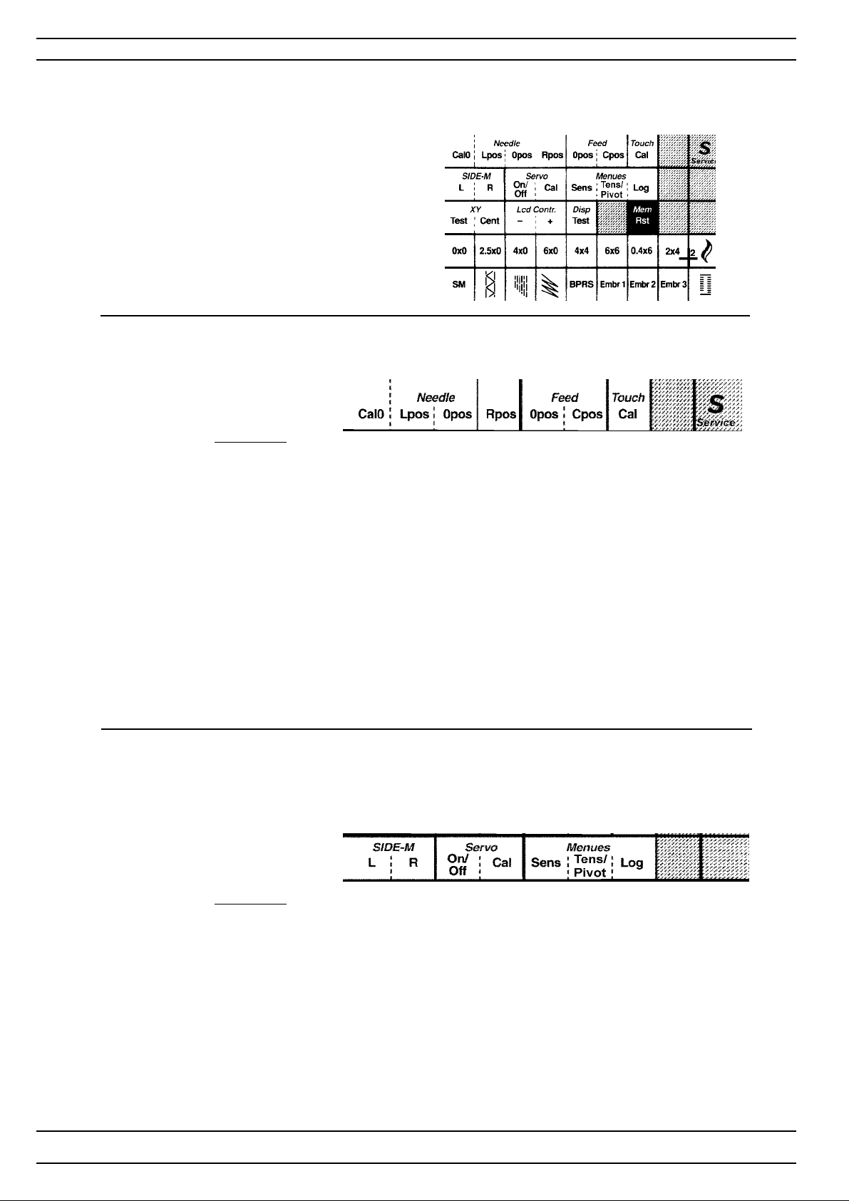
Service Program - Quilt Designer
Service program - Quilt Designer
Functions of the service menu 1.
Service cassette
Row 1
Toucharea
Needle Cal 0 Upper needle position - Checking the centre position of the needle step
motor.
Lower needle position - Checking the centre position of the feeding
step motor.
Needle Lpos Is used for pre-setting the needle stepmotor .
The needle stepmotor of the needle now takes its left calibration
position.
Needle Opos Is used when setting the centre position of the needle.
The step motor of the needle is now in its centre position.
Needle Rpos Is used for pre-setting the needle stepmotor.
The step motor of the needle now takes its right calibration position.
Feed 0 pos Is used when coarse-adjusting the stitch length balance
The feed dog should now stand still ( 0-feeding).
Feed C pos Is used when pre-setting the feeding step motor .
The step motor now takes its calibration position.
Service cassette
Row 2
Toucharea
SIDE-M L Side motion - Left position
R Side motion - Right position
Servo
On/off Sewing head - Pivot function ON / OFF.
Ca l Sewing head takes its calibration position.
Menues
Sens Sensor check - to Servicemenu 2
Tens Setting the upper thread tension - to Service menu 3
Lo g Time function of the machine- to Service menu 4
broidered on.
de motion L Left position.
52
104 72 53-26
Page 53
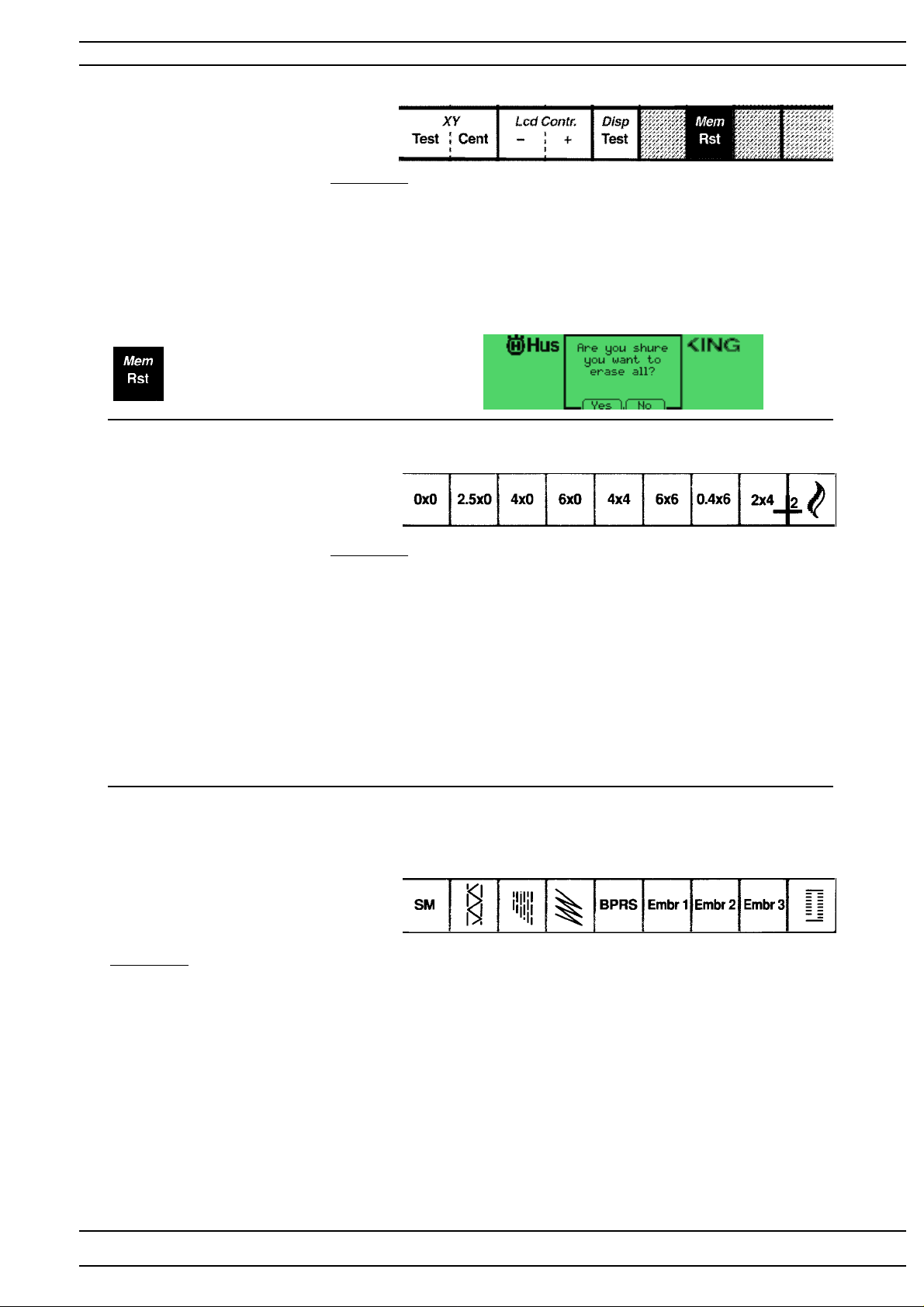
Service Program - Quilt Designer
Service cassette
Row 3
Toucharea
X-Y Test --X- Y Cent --Lcd-Contr + Increases the light in the LCD
Lcd-Contr - Decreases the light in the LCD
Display test. Disp The Display shall change between 4 different squared pattern,
after the check is done the machine will go back to the latest
choosen menu or Service menu.
Mem / Rst is used to erase everything
programed in the programmable
memories ot the machine
Service cassette
Row 4
Service cassette
Row 5
Toucharea
Toucharea
1 0x0 Is used when coarse-adjusting the stitch length balance
2 2,5x0 The machine sews straight stitch 2,5 mm.
3 4.0x0 The machine sews straight stitch 4 mm.
4 6,0x0 The machine sews straight stitch 6 mm.
5 4x4 The machine sews a zig zag stitch 4x4 mm.
6 6x6 The machine sews a zig zag stitch 6x6 mm.
7 0,4x6 The machine sews a zig zag stitch 0,4x6mm
8 2x4 The machine sews a zig zag 2x4 mm
9-- --
1 SM The machine sews a side motion stitch.
2 Hem --3 Mend Is used for fine-adjusting the stitch length balance.
4MM
5 Re p The machine sews signs B,P,R,S.
6 Embr 1 -- 7 Embr 2 -- 8 Embr 3 -- 9 --- ---
1 2 3 4 56 78 9
The feed dog should now stand still ( 0-feeding).
1 2 3 4 56 78 9
The machine now sews a pre-programed mending stitch.
104 72 53-26
53
Page 54
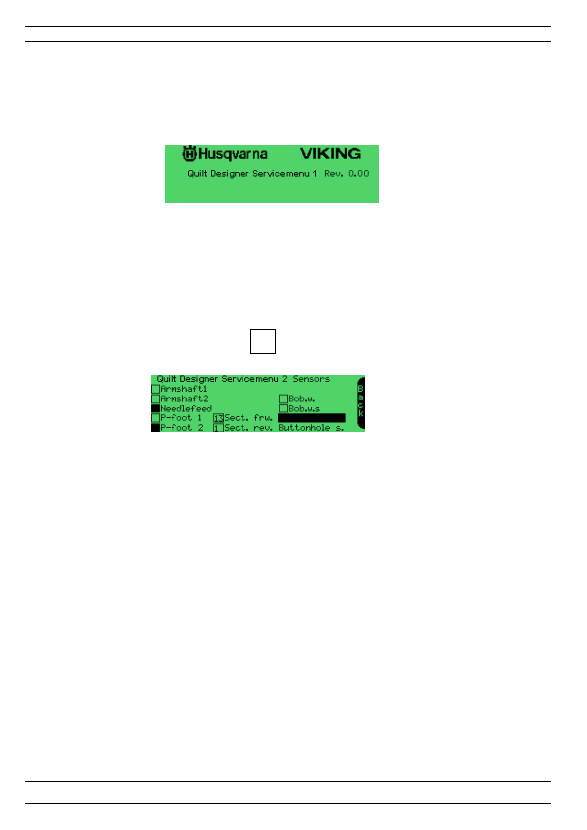
Service Program - Quilt Designer
Function of the Service menu 1
The revision of the program memory
Functions of the service menu 2 - Sensor check
Operation
Get into the service program, touch Menues Sens on Row 2
Active square is filled
Armshaft1 Check of armshaft's first sensor (stop right function)
Armshaft2 Check of armshaft's second sensor (stop right function)
Needlefeed Check of needle
P-foot 1 Check of presserfoot's first sensor
P-foot 2 Check of presserfoot's second sensor
Sect.frw
Sect.rev
Bob.w. The bobbin winding sensor
Bob.w.s. The bobbin winding sensor -Indicates when bobbin is wounded.
Buttonhole s. Button hole sensor check
Back Back to service menu 1
54
104 72 53-26
Page 55
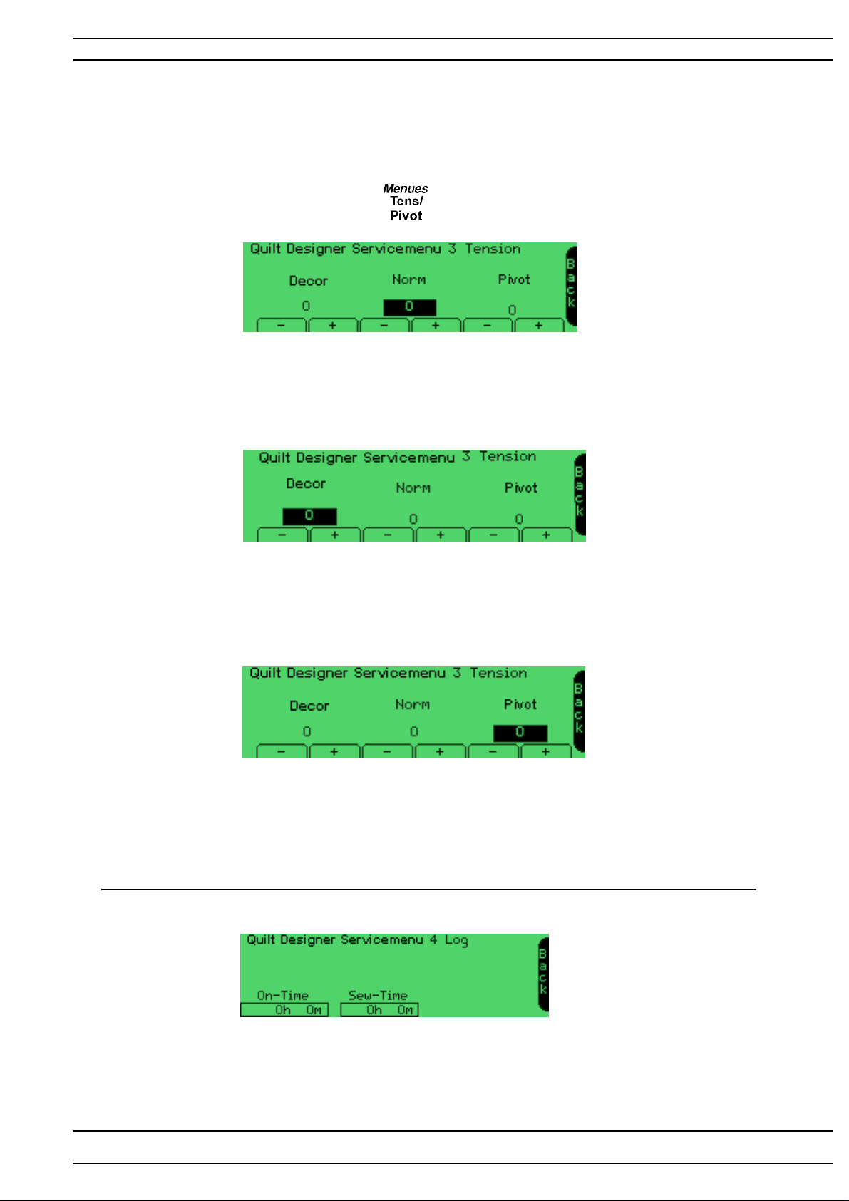
Service Program - Quilt Designer
Functions of the service menu 3 - Quilt Designer
Upper thread tension - Pivot position
T o facilit ate the setting of the upper thread tension there is an electronic adjustment in the Service menu 3.
Operation
Get into the service program. Touch Menues row 2. The machine will enter Service Menu 3.
T ension "Norm"
Is used for adjustment of the HIGHER upper thread tension at normal sewing . The value is normally set
between +10 and -10. The value on the display is changed gradually each time you touch the touch area.
Note! There are limitations in the setting. The value of the setting could be higher then +10 or
lower then -10 .
T ension "Decor"
Is used for adjustment of the LOWER upper thread tension at decorative sewing.The value is normally set
between +10 and -10.
The value on the display is changed gradually each time you touch the touch area
Note! There are limitations in the setting. The value of the setting could be higher +10.
Pivot
Is used for adjustment of the presser bars pivot position. The value is normally set between +10 and -10.
The value on the display is changed gradually each time the touch area is touched
NOTE! the pressarbar must be re-calibrated before the setting has any affect.
Functions of the Service Menu 4 - Log menu
On time Indicates how many hours and minutes the machine has been on
Sew-Time Indicates how many hours and minutes the machine has been sewed on
104 72 53-26
55
Page 56
Service Program - Quilt Designer
Calibration of the touch panel - Quilt Designer
How to synchronize the touch area of the touch panel with the symbols on the screen.
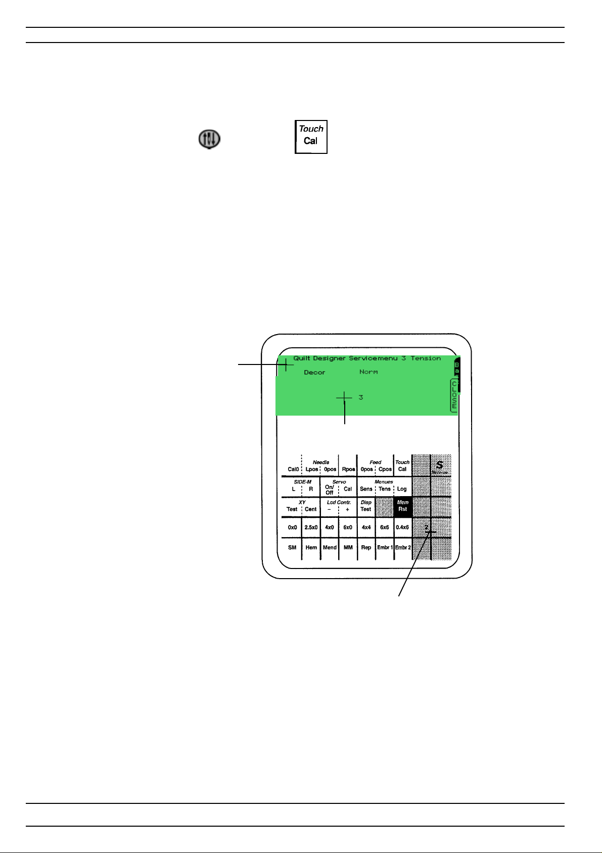
Get into the service program of the machine.
Press the needle stop button or touch Touch ,row 1 on the service card.
1. Touch with a blunt object in the center of cross 1 so that it disapeares. Indicated as the First
calibration mark on the illustration.
2. Touch with a blunt object in the center of cross 2, indicated Second calibration mark
on the illustration.NOTE ! The second calibration mark is the red cross on the Service card.
3. Touch the 3rd cross and the machine will return to Service menu or the menu that was open before the
Calibration is done . NOTE! The Third calibration mark will only appear in the display when the
second calibration mark is calibrated.
First calibration mark
Third calibration mark
Second calibration mark
Set the calibration of the touch panel with gauge 412 22 33-01
56
104 72 53-26
Page 57
Service Program- Quilt Designer
Update of the memory - Quilt Designer (Read & write unit)
The Quilt Designer has a memory in which the characteristics and stitches of the machine are stored.
In order to update the memory the machine has an update mode.
The program memory on Quilt Designer is updated through the Programmable d-Card.
Revision of the program
The revision of the program can be seen in the middle of the welcome screen or checked in the service
program menu 1.
How to transfer the Quilt Designer program memory to a programmable d-Card
A d-Card reader/writer is needed to transfer the program memory to programable d-Card.
The latest version of the Quilt Designer program memory can be found on Husqvarna Vikings Internet page.
NOTE! All data that is stored on the programmable d-Card will be erased when the Quilt Designer
program memory is transfered to the programmable d-Card.
Make sure that the d-card reader/writer is properly connected to the computer before starting the download.
1. Insert a programmable d-Card in the d-Card reader/writer unit.
2. Go to the Husqvarna Viking update page on the Internet. Click on the Quilt Designer update icon.
3. A update program will st art. Follow the instructions in the program.
4. Remove the Programmable d-Card when the update files are transfered to it.
How to update the machine
1. Insert the programmable d-Card with the new memory
information in the d-Card reader in the machine.
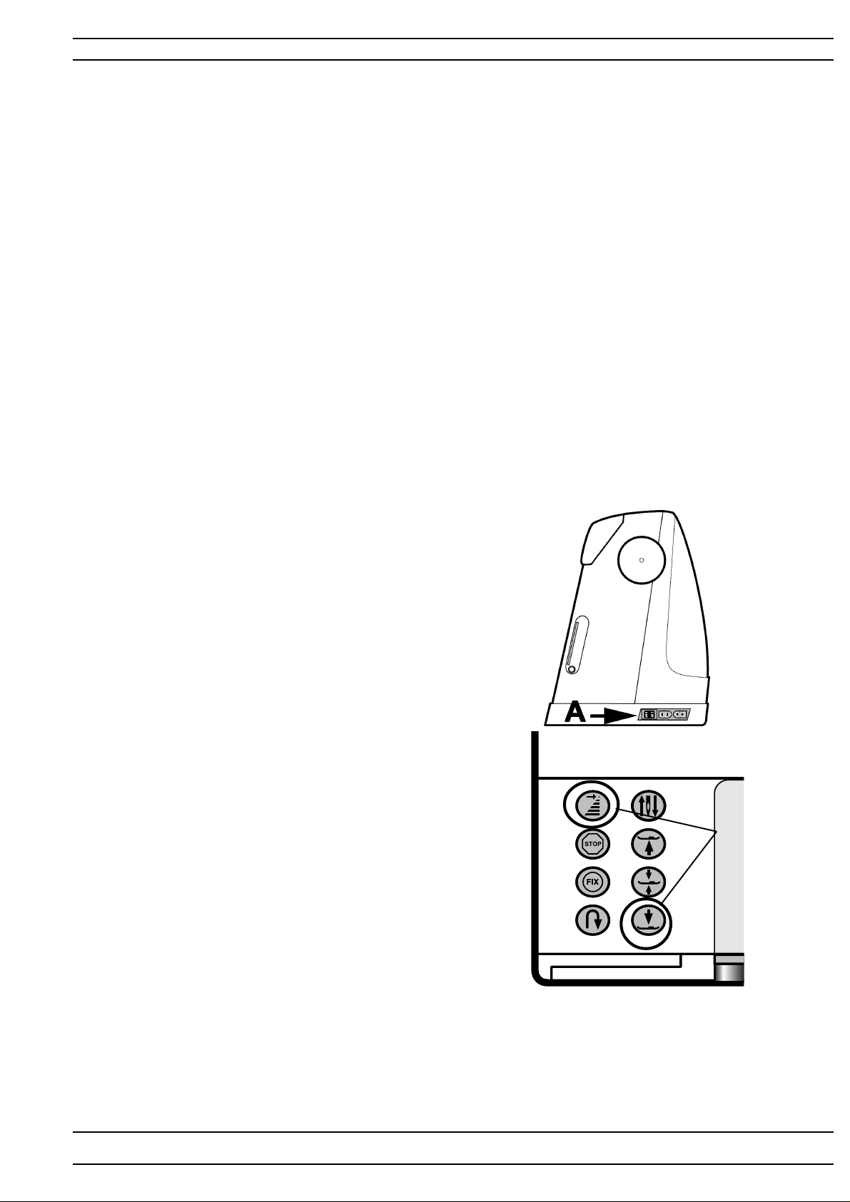
2. Get into the update mode of the machine
by pressing the presser foot down button
and the stitch re-start button while
the main switch (A) is turned on.
3. The memory will now automatically
be updated.
4. When the memory of the machine is correctly
updated REST ART is indicated on the screen.
Then...
-Turn off the machine.
-Remove the d-Card.
Press
5. Re-start the machine and check the revision (see above).
NOTE! If the Main PC board is changed the memory always has to be updated with the latest
version.
104 72 53-26
57
Page 58
Covers
Upper rear cover
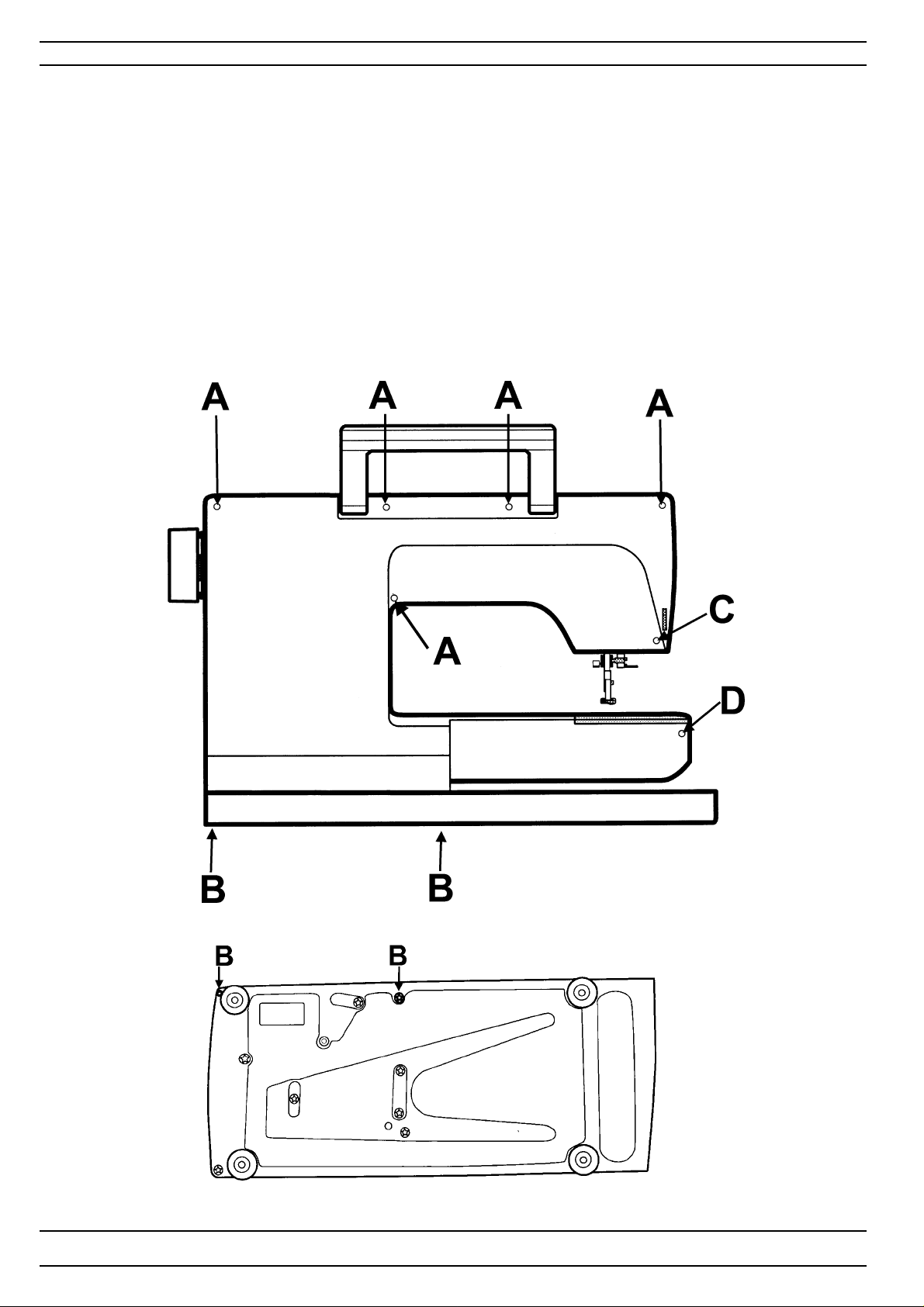
1. Remove the five screws (A).
2. Remove the two screws (B).
3. Remove the screw (C).
Lower rear cover
1.Remove the screw (D).
2. Remove the lower rear cover pulling it backwards on the right-hand side and at the same time push the front
covers upper and lower side of the free arm together.
3. Remove the socket of the embroidery unit by bending it away from the snap in the in
the cover with a screwdriver on the corner behind the socket.
58
104 72 53-26
Page 59
Covers
Front cover - Designer I
Dismounting
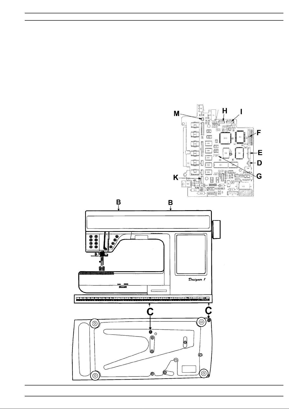
1. Dismount the rear covers.
2. Remove the button for the bobbin winding sensor stop, by pulling it straight out.
3. Remove the two screws (B) from behind.
4. Remove the two screws (C) in the base plate.
5. Turn the hand wheel until the needle is in its lowest position, so the thread take up lever
is out of the way .
6. Carefully bend away the front cover from the hand wheel and pull it straight out.
NOTE! Pull carefully the front cover away in order not to damage the cables.
7. Remove the cable (D) of theLCD transformer box and
the cable(E) of the LCD .
8. Remove the band cable (G) of the touchpanel board
from the circuit board by pulling the outer covering
of the white switch outwards.
9. Remove the cable (F) of the floppy disk drive
from the circuit board by pulling the outer covering
of the black switch outwards.
10. Remove the two cables (H) and (I)
of the push button assembly .
1 1. Remove the cable (K) of the thread tension.
12 Remove the cable (M) of the lamp.
13. Remove the earth cable from the LCD frame.
Mounting
Mount in reverse order
104 72 53-26
59
Page 60
Covers
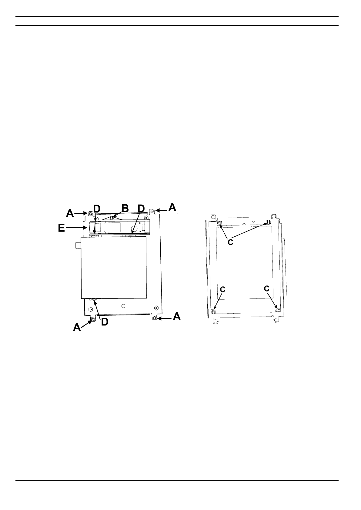
Parts of the front cover - Designer I
LCD
Dismounting
1. Dismont the rear covers
2. Dismount the front cover.
3. Remove the LCD frame from the front cover by dismouning the 4 screws (A).
4. Remove the LCD light cable (E)
5. Remove the LCD by dismounting the 4 screws (C).
Mounting
Mount in reverse order.
Note! The black sealing should be on the the LCD.
Touch Panel
Can be removed after dismounting the LCD frame.
NOTE! When a T ouch p anel is changed the new one must be re-calibrated
Floppy disk drive
Dismounting
1. Dismont the rear covers
2. Dismount the front cover.
3. Remove the LCD frame from the front cover by dismounting the 4 screws (A),
4. Remove the transformer box by dismounting the screw (B).
5. Remove the Floppy disk drive by dismount the 3 screws (D).
6. Remove the cable from the floppy disk drive.
Mounting
Mount in reverse order.
NOTE! When mounting the cable the contact area of the cable should be facing the floopy disk drive
60
104 72 53-26
Page 61
Covers
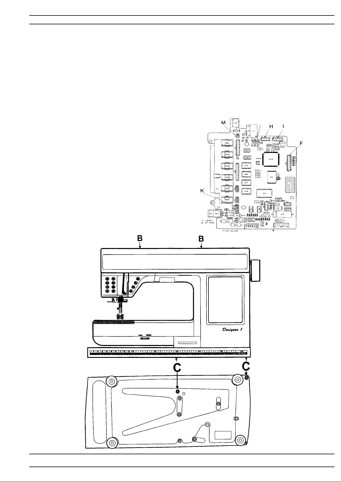
Front cover - Designer II and Quilt Designer
Dismounting
1. Dismount the rear covers.
2. Remove the button for the bobbin winding sensor stop, by pulling it straight out.
3. Remove the two screws (B) from behind.
4. Remove the two screws (C) in the base plate.
5. Turn the hand wheel until the needle is in its lowest position, so the thread take up lever
is out of the way.
6. Carefully bend away the front cover from the hand wheel and pull it straight out.
NOTE! Pull carefully the front cover away in order not to damage the cables.
7. Remove the cable (F) of the presentation unit.
8.
Designer II :
Remove the two cables (H) and (I) of the push button assembly .
Quilt Designer:
Remove the cable (I) of the push button assembly .
9. Remove the cable (K) of the thread tension.
10.Remove the cable (M) of the lamp.
1 1.Remove the earth cable from the LCD frame.
Mounting
Mount in reverse order
104 72 53-26
61
Page 62
Covers
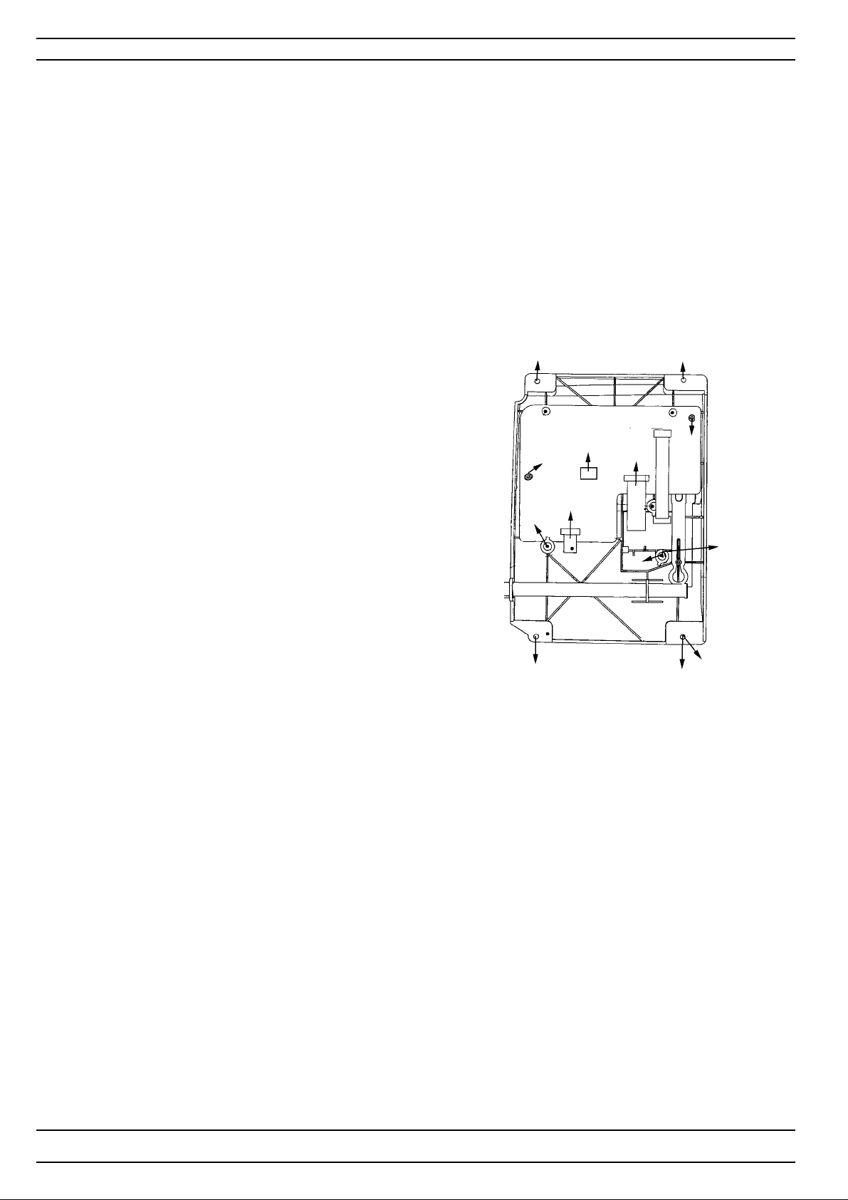
Parts of the front cover - Designer II and Quilt Designer
Presentation Unit
Dismounting
1. Dismont the rear covers
2. Dismount the front cover.
3. Remove the T ouch screen cable (A) by pulling the cable down.
4. Dismount the 4 screws (B) and then remove the Spring (C) and
the Presentation unit from the front cover .
Mounting
Mount in reverse order.
Note! The Touch Panels ESD-cable should be located under the spring (C).
Presentation Unit - d-Card Connection board
1. Remove the cable between the Display Board and
d-Card connecting board
2. Remove screw (D) and the holder (E) and
remove the memory connecting board.
Mounting
Mount in reverse order.
Presentation Unit - Display board
1. Remove the cable between the Display Board and
d-Card connecting board
2. Remove the LCD cables (F) and (G) by pulling
the outer covering of the black switch outwards.
3. Remove three screws (H) and the holder (J)
and remove the memory connecting board.
Mounting
Mount in reverse order.
B
J
B
H
F
A
G
D
B
H
E
C
B
Touch Panel
Dismounting
T ouch Panel can be removed first af ter dismounting of the Presentation unit.
Mounting
Mount In reverse order
When mounting the Touch Panel, please check so it’s correctly inserted against
the frontcover.
Note! The cut corner of the Touch Panel must be placed on the upper left side
inthe frontcover.
NOTE! When a Touch panel is changed the new one must be re-calibrated.
62
104 72 53-26
Page 63
Dismantling and mounting
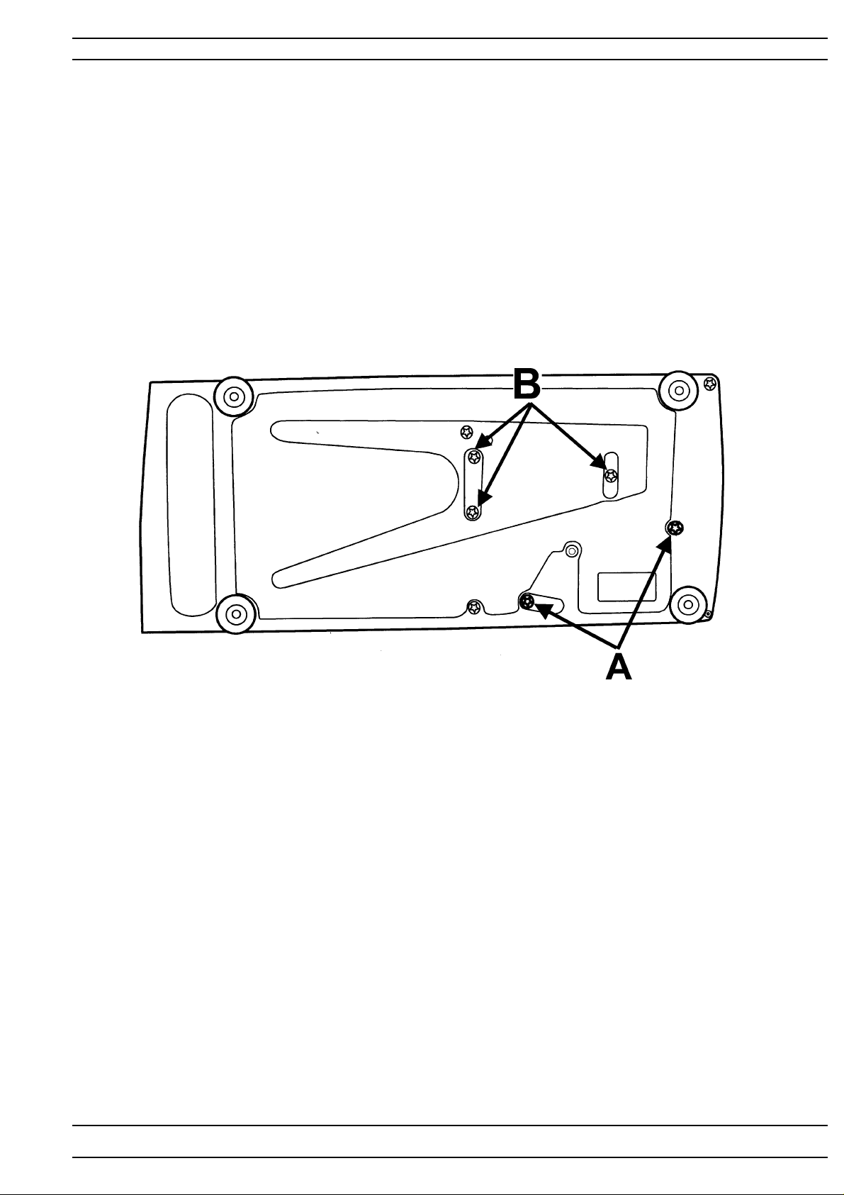
Base Plate
Dismounting
1. Dismount the upper and lower rear cover.
2. Dismount front cover.
4. Dismount the 2 screws (A) for the transformer.
3. Dismount the 3 screws (B).
104 72 53-26
63
Page 64
Dismantling and mounting
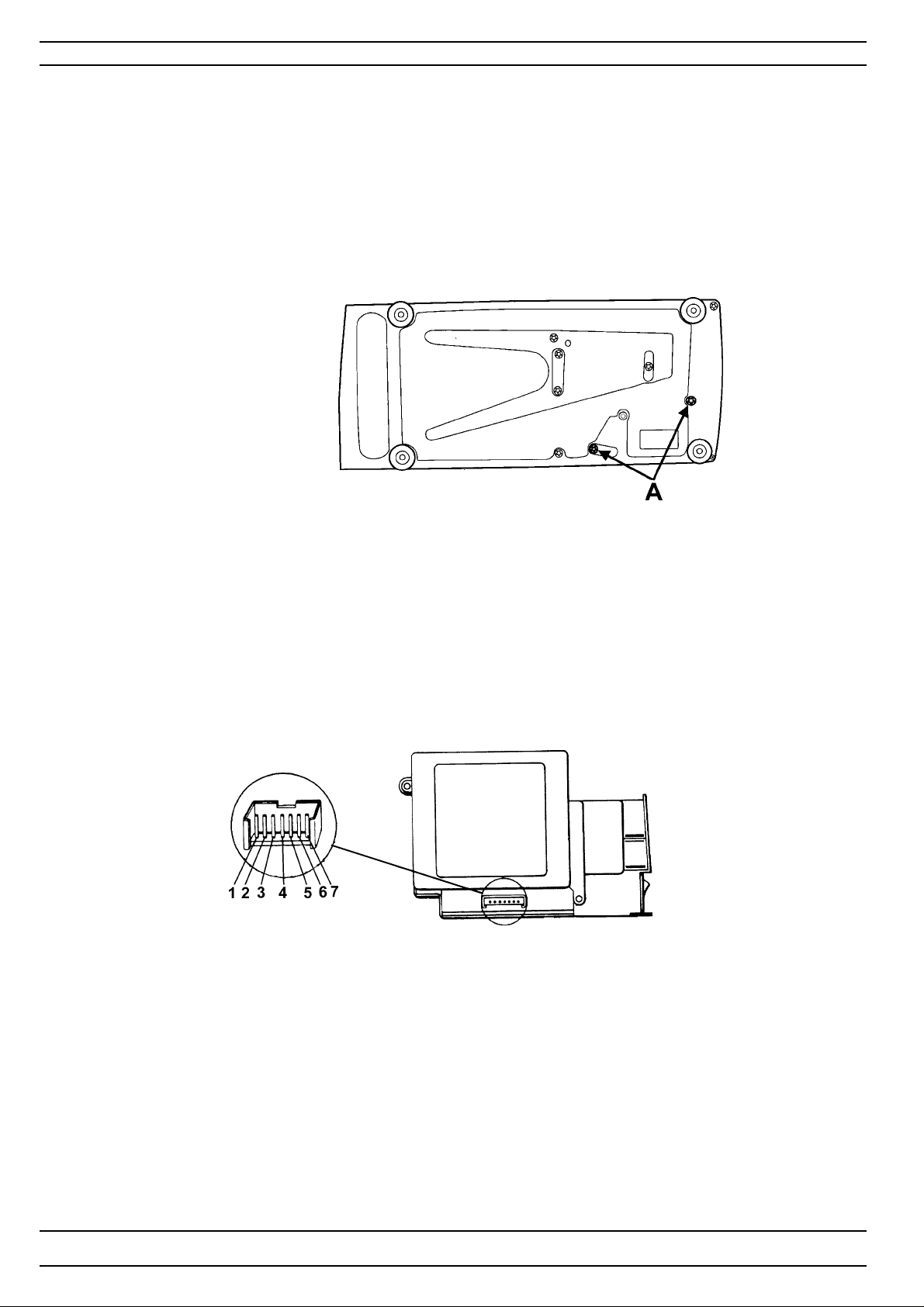
Transformer- Designer I, Designer II
Dismounting
1. Dismount upper rear cover.
2. Loosen the two screws (A) of the transformer from below in the base plate.
3. Push the transformer to the right so that the mains switch part is exposed from
the base plate and lift it upwards.
4. Unhook the cable to the circuit boards from the transformer.
Checking the transformer
Connect the transformer to mains.
Measure the tension and resistence between the contact pins.
1 shall be approx. + 5 Volt computer.
2-3 - Grounding
4-5 shall be approx. + 26 Volt S tep motor, drive motor.
6- 7 shall be approx. 100-0 k Ohm Foot control connected
NOTE! The Transformer is a switched mode type power supply and can operate
between 100-240 volt and 50-60 Hz.
64
104 72 53-26
Page 65
Dismantling and mounting
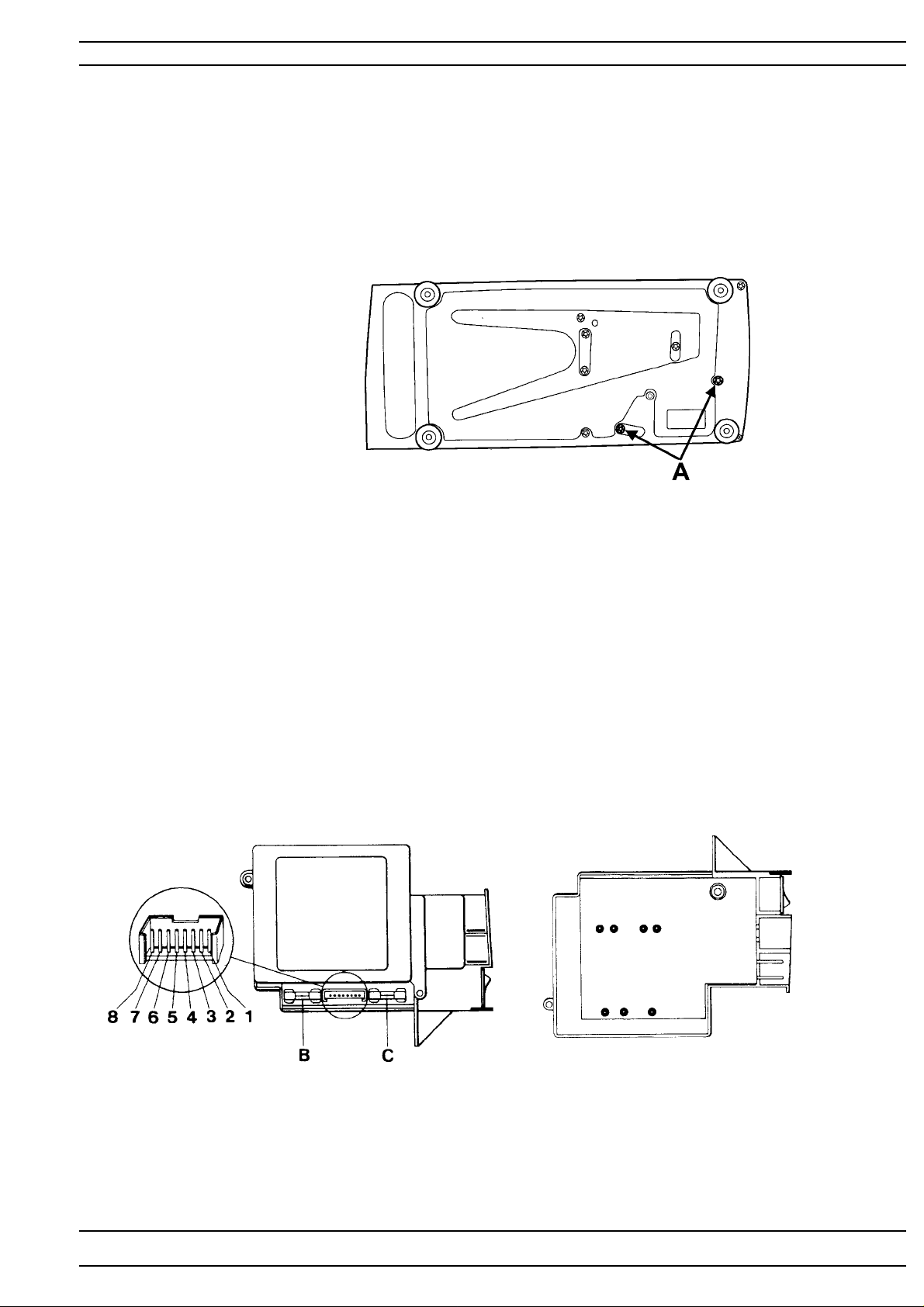
Transformer- Quilt Designer
Dismounting
1. Dismount rear cover .
2. Loosen the two screws (A) of the transformer from below in the base plate.
3. Push the transformer to the right so that the mains switch part is exposed from
the base plate and lift it upwards.
4. Unhook the cable to the circuit boards from the transformer.
Checking the transformer
Connect the transformer to mains.
Measure the tension and resistence between the contact pins.
1-3 shall be approx. 13 Volt AC Lamp, computer .
4/5-6/7 shall be approx. 28 Volt AC S tep motor , drive motor .
2-8 shall be approx. 100-0 k Ohm Foot control connected
Fuses
On the circuit board of the transformer there are two fuses.
They can be exchanged without disassemble the transformer.
Fuse (B): for 120 V machines 3.5 A/250 V
for 220 V machines 6.3 A/250 V
Fuse (C): 2 A/250 V
Dismounting the transformer and the circuit board
1. Remove the lower part of the transfomer casing.
2. Remove the soldering from the 7 connections of the transformer to the circuit board.
3. Remove the circuit board.
104 72 53-26
65
Page 66
Dismantling and mounting
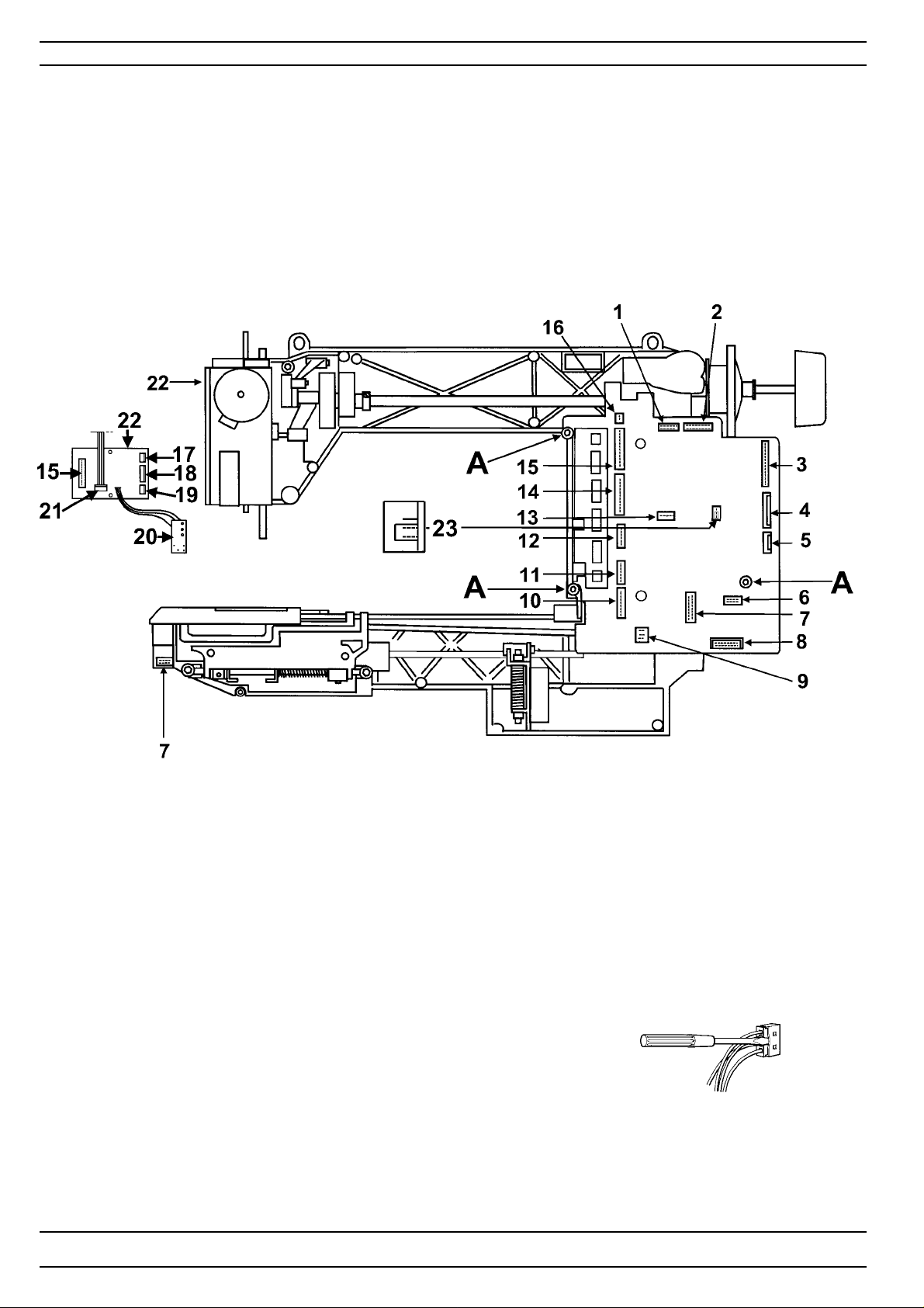
Circuit board - Circuit diagram - Designer I
Dismounting
1. Dismount rear cover .
2. Dismount front cover .
3. Loosen the 3 screws (A) holding the circuit board and the cooling plates
and lift out the board from the machine.
4. Loosen the cables from the circuit board according to below:
(1) Right push buttons assembely (12) Feeding step motor
(2) Left push button assembely (13) Touch foil key board
(3) Floppy disk drive (14) Embroidery Unit
(4) LC Display (15) Conecting Sewing head board-ciruit board
(5) LC display transformer box (16) Lamp - front cover
(6) Stop right board (17) Lamp - Sewing head
(7) Thread cutter assembely (18) Step motor of the presser foot lifter
(8) Transformer (19) Step motor of the needle.
(9) Motor. Red cable down (20) Sensor of the presserfoot lifter
(10) Thread tension (21) Pressar foot sensor
(1 1) Side feedings step motor (22) Sewing head card
(23) Switch jumper. Note the position
The contacts can be loosened by cautiously bending away the outer
covering with a thin screwdriver.
Note! If the Main PC board is changed
1. the memory must always be updated to the latest version.
2. the touch panel must be calibrated.
3. the upper tread tension must be set
4. the sewing heads pivot position must be set
66
104 72 53-26
Page 67
Dismantling and mounting
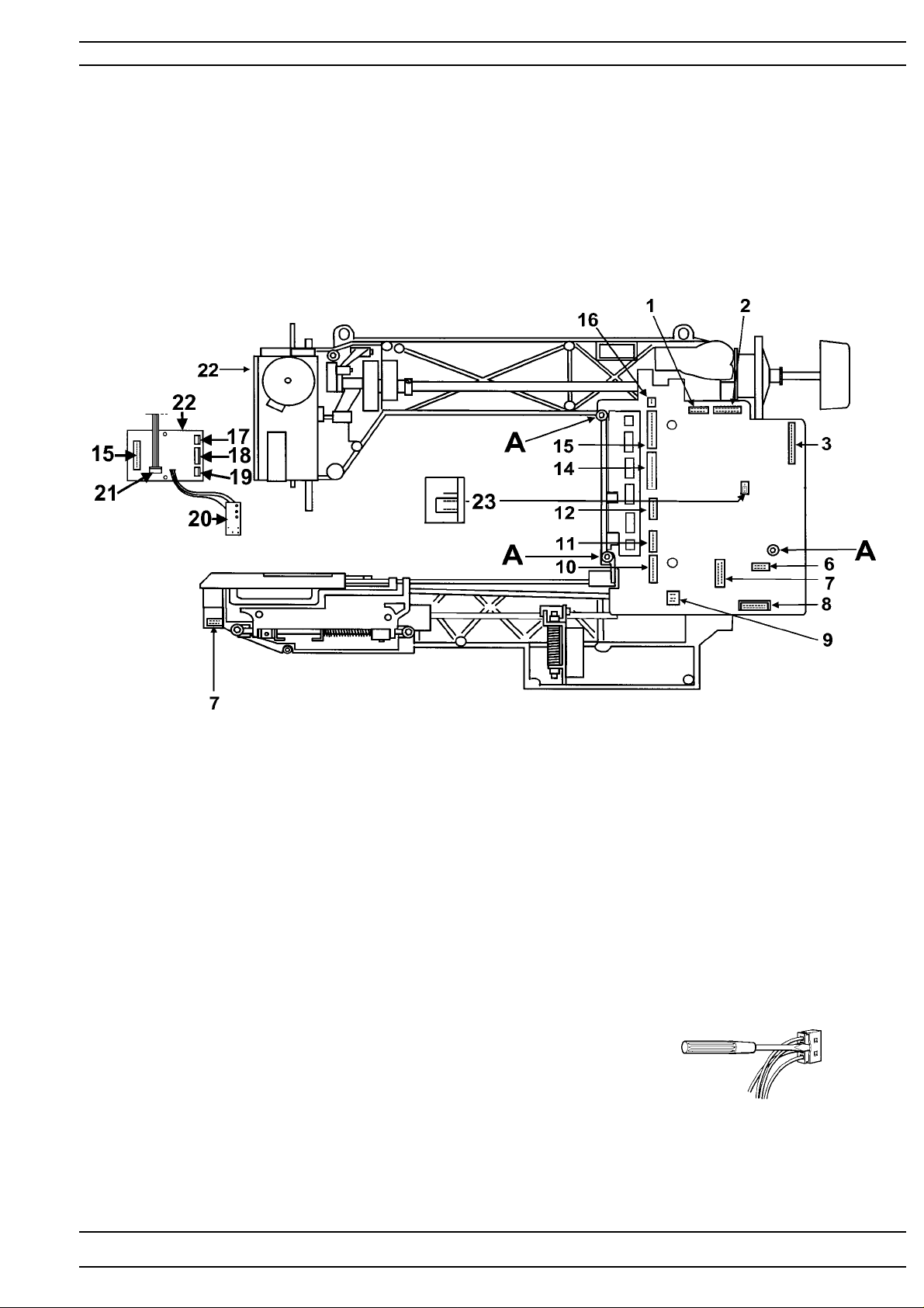
Circuit board - Circuit diagram - Designer II
Dismounting
1. Dismount rear cover .
2. Dismount front cover .
3. Loosen the 3 screws (A) holding the circuit board and the cooling plates
and lift out the board from the machine.
4. Loosen the cables from the circuit board according to below:
(1) Right push buttons assembly (12) Feeding step motor
(2) Left push button assembly
(3) Presentation Unit connector (14) Embroidery Unit
(15) Conecting Sewing head board-ciruit board
(16) Lamp - front cover
(6) Stop right board (17) Lamp - Sewing head
(7) Thread cutter assembly (18) Step motor of the pressar foot lifter
(8) Transformer (19) Stepmotor of the needle.
(9) Motor. Red cable down (20) Sensor of the pressarfoot lifter
(10) Thread tension (21) Pressar foot sensor
(1 1) Side feeding step motor (22) Sewing head card
(23) Switch jumper. Note the position
The contacts can be loosened by cautiously bending away the outer
covering with a thin screwdriver.
Note! If the Main PC board is changed
1. the memory must always be updated to the latest version.
2. the touch panel must be calibrated.
3. the upper tread tension must be set
4. the sewing heads pivot position must be set.
104 72 53-26
67
Page 68
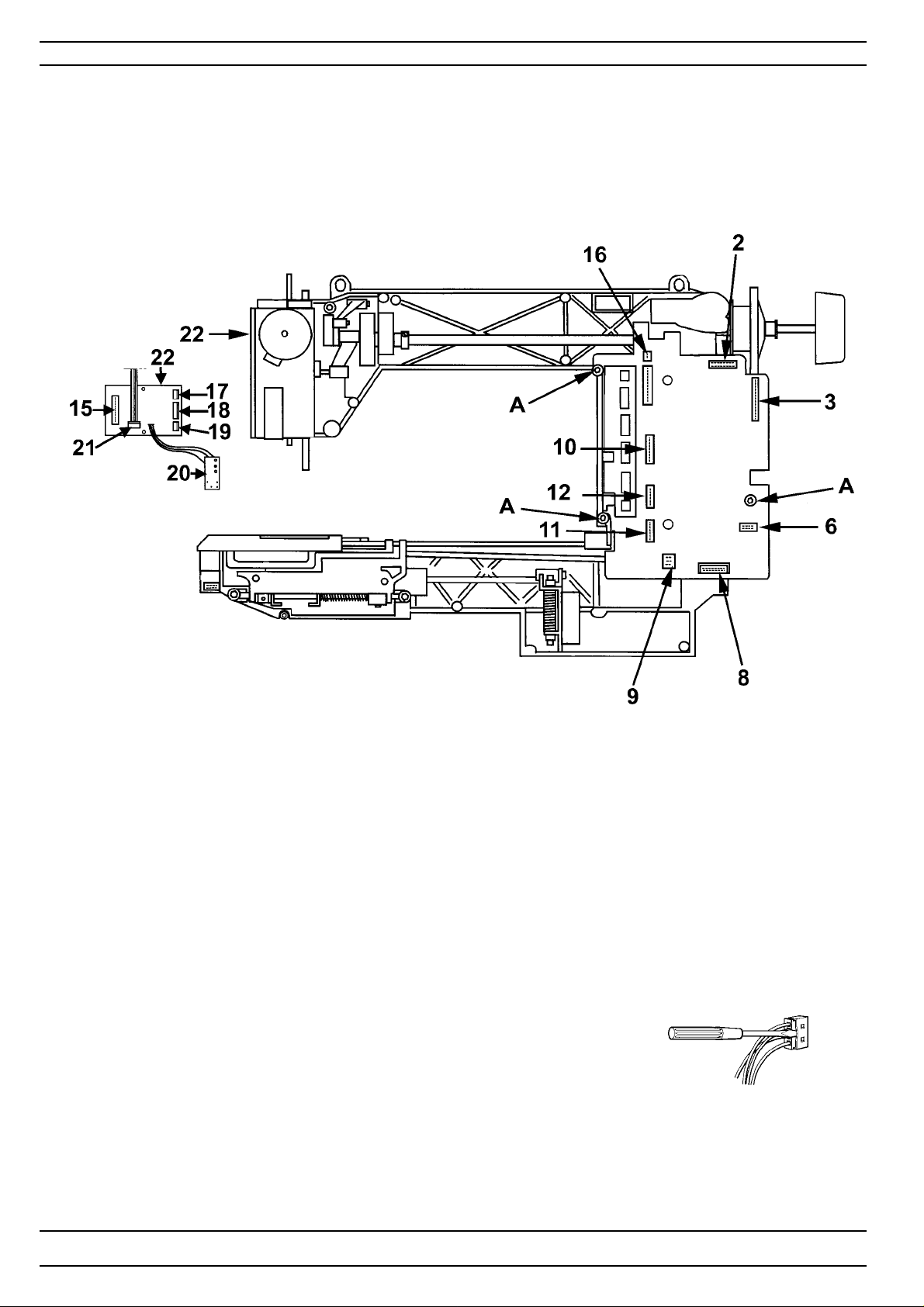
Dismantling and mounting
Circuit board - Circuit diagram - Quilt Designer
Dismounting
1. Dismount rear cover .
2. Dismount front cover .
3. Loosen the 3 screws (A) holding the circuit board and the cooling plates
and lift out the board from the machine.
4. Loosen the cables from the circuit board according to below:
(12) Feeding step motor
(2) Left push button assembly
(3) Presentation Unit connector
(15) Conecting Sewing head board-ciruit board
(16) Lamp - front cover
(6) Stop right board (17) Lamp - Sewing head
(18) Step motor of the pressar foot lifter
(8) Transformer (19) Stepmotor of the needle.
(9) Motor. Red cable down (20) Sensor of the pressarfoot lifter
(10) Thread tension (21) Pressar foot sensor
(1 1) Side feeding step motor (22) Sewing head card
The contacts can be loosened by cautiously bending away the outer
covering with a thin screwdriver.
Note! If the Main PC board is changed
1. the memory must always be updated to the latest version.
2. the touch panel must be calibrated.
3. the upper tread tension must be set
4. the sewing heads pivot position must be set
68
104 72 53-26
Page 69
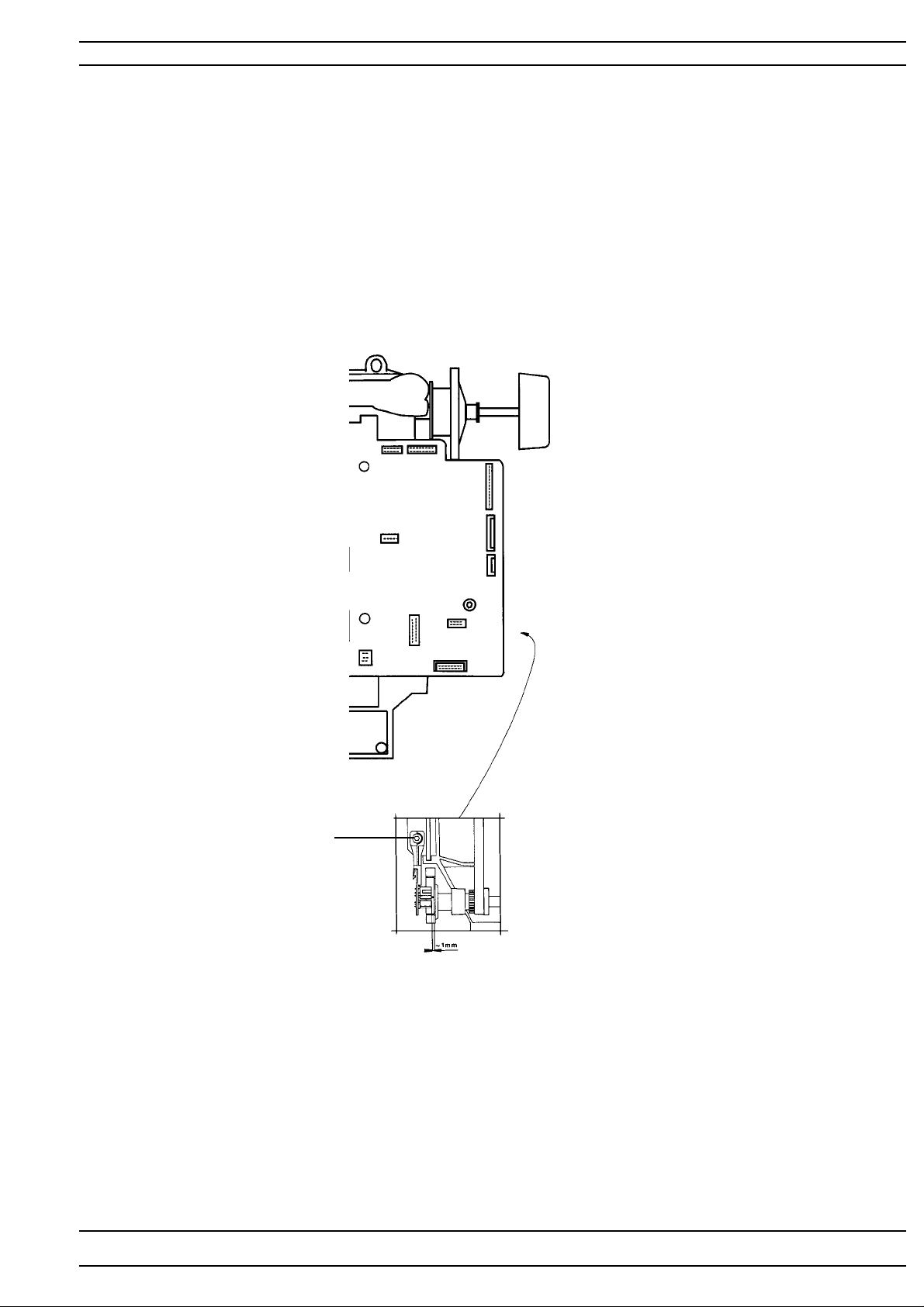
Dismantling and mounting
Stop right circuit board
Dismounting
1. Dismount rear cover .
2. Dismount front cover .
3. Disconnect the stop right board cable from the circuit board
3. Dismount the screw (A) thats holds the stop right circuit board.
4. Cautiously remove the circuit board from the support by bending its lower end
outwards and thereafter pulling it downwards .
A
NOTE! Check that the lower shaft sensor is mounted at a distance of approx. 1 mm from
the screen. ( see illustation.)
104 72 53-26
69
Page 70
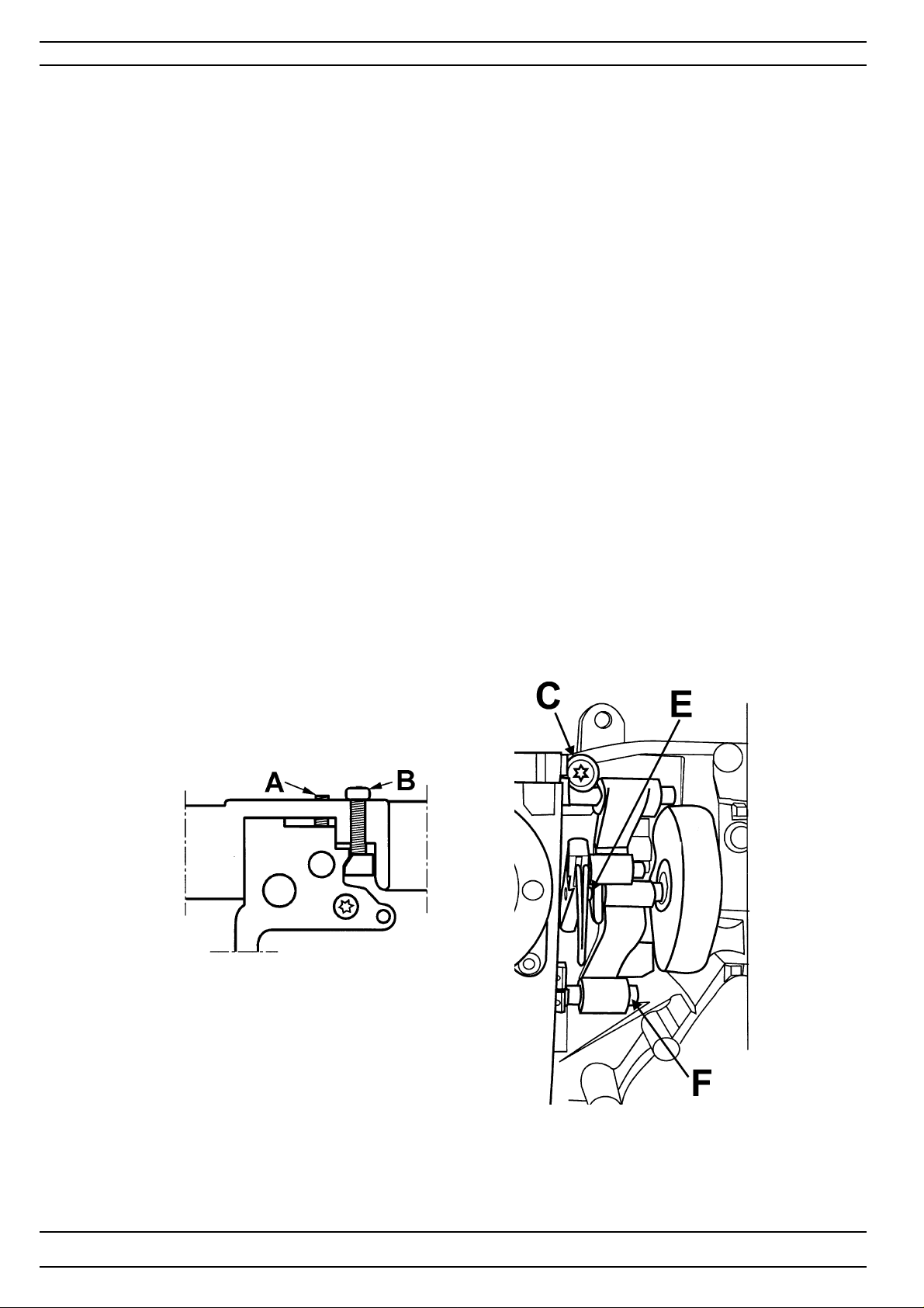
Dismantling and mounting
Sewing head
Dismounting
1. Dismount rear covers and front cover.
2. Dismount the cable from the main circuit board to the sewing head connection board.
3. Loosen the screw (A)
4. Loosen screw (B) and remove the block (D) by pushing the screw (B) down.
5. Remove screw (C).
6. Unhook the sewing head from the sewing machine arm.
7. Unhook the sewing head from the stud (E) of the thread take-up
lever and the connecting rod (F).
Mounting
1. Hook on the sewing head to the connecting rod (F) and the stud(E) of the thread take-up lever .
2. Place sewing head in the machine.
3. Tighten the screw (C).
4. Mount the block (D) together with the screw (B) in the machine and tighten
Set thereafter:
8. The gap between the needle and the hook
6. The centre position of the needle.
7. Setting of the needle in relation to the preeserfoot.
10. Needle height
19. Threading device.
22. Stitch length balance
29. Pivot position
70
104 72 53-26
Page 71
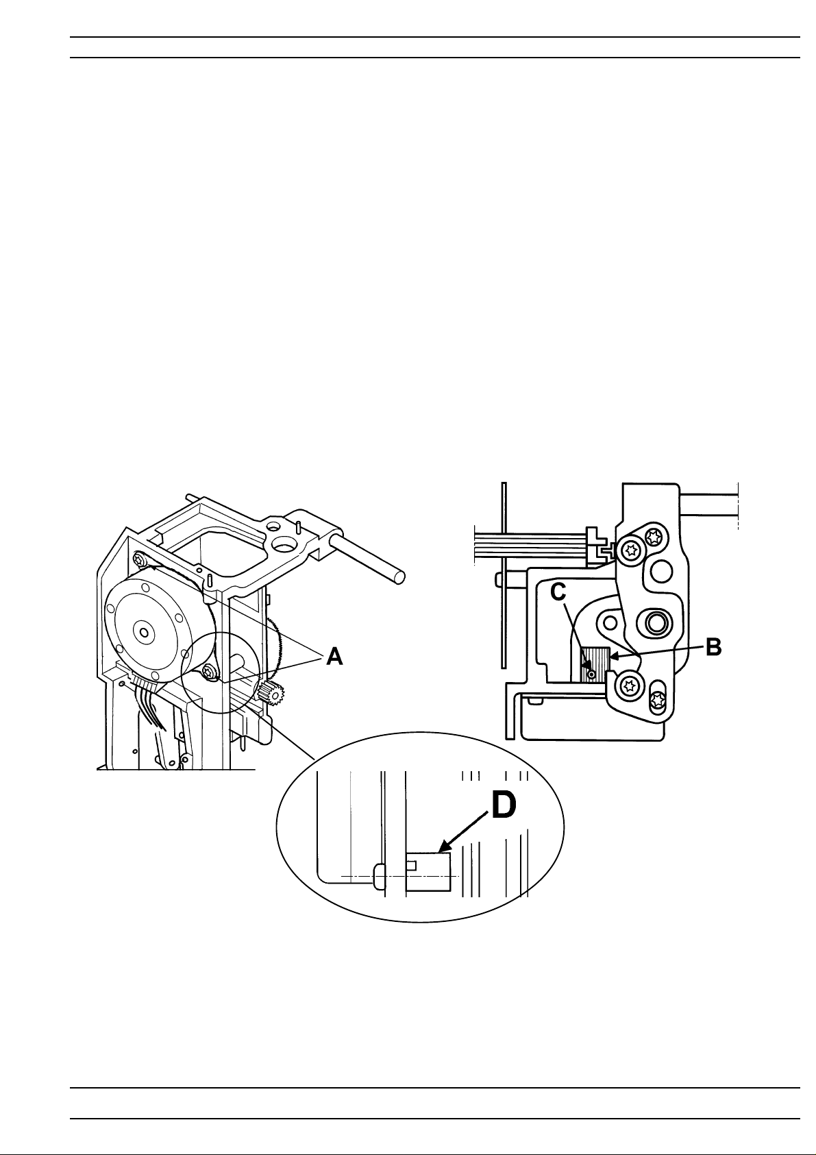
Dismantling and mounting
The step motor of the needle
Dismounting
1. Dismount rear covers .
2. Dismount front cover .
3. Dismount the step motor by removing the 2 screws (A) .
4. Dismount the step motor cable on the sewing head connection board.
Mounting
1. Attach the cable to the sewing head connection board.
2. Set the needle in it's center position.
3. Position the cogwheel (B) so that the screw (C) is pointing upwards.
4. Mount the callibration stop (D). Note the position.
5. Mount the step motor.
6. Position the step motor and tighten the screws (A).
Set thereafter:
6. The centre position of the needle.
104 72 53-26
71
Page 72
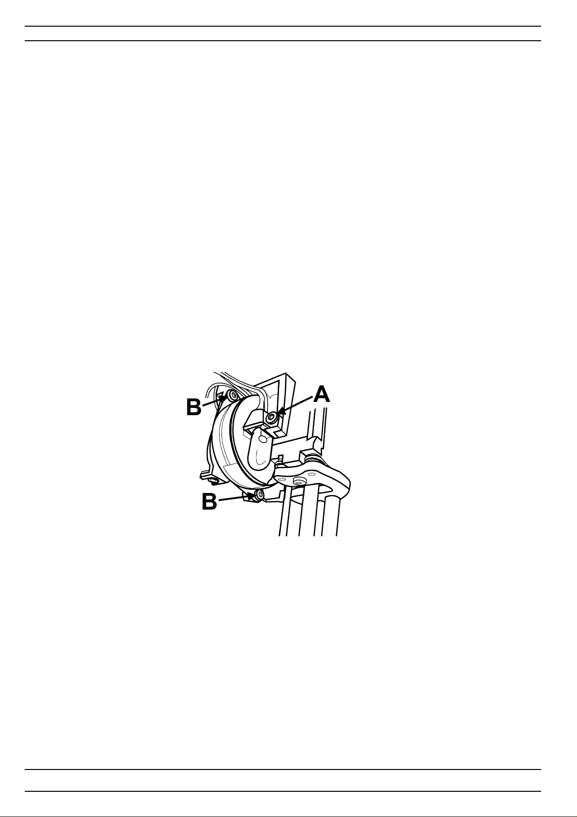
Dismantling and mounting
The step motor of the presserfoot lifter
Dismounting
1. Dismount rear covers .
2. Dismount front cover .
3. Dismount the lamp of the sewing head by removing the screw (A)
4. Dismount the cable from the sewing head connection board.
5. Dismount the step motor by removing the 2 screws (B) .
Mounting
1. Attach the cable to the sewing head connection board.
2. Mount the step motor. and tighten the screws (B).
3. Mount the lamp of the sewing head.
72
104 72 53-26
Page 73
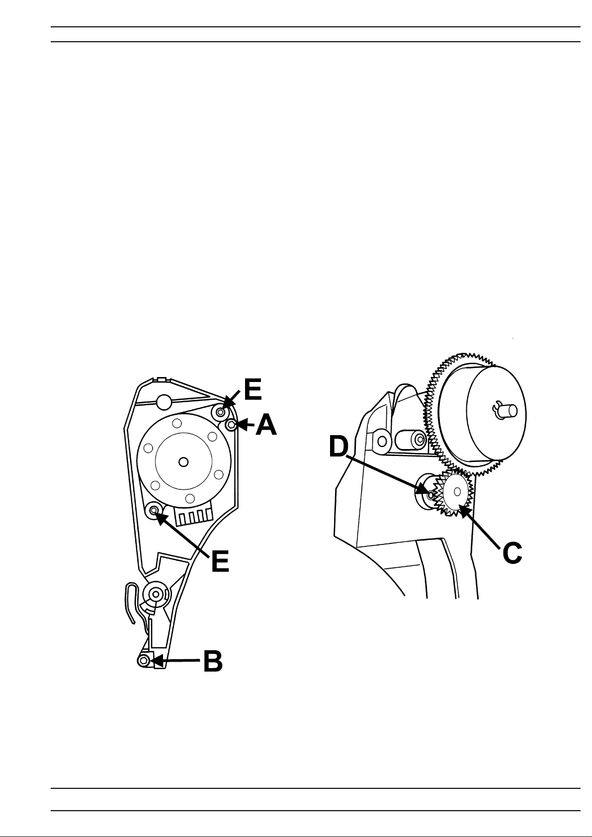
Dismantling and mounting
The thread tension compl.
Dismounting
1. Dismount rear covers.
2. Dismount the front cover.
3. Dismount the thread tension cover by taking a firm grip on the top of the cover
and then carefully pulling it away from the front cover.
4. Dismount the push button board by disconnecting it from the cable .
5. Dismount the cable holder from the cable on the inside of the front cover.
6. Dismount the thread tension by removing the 2 screws (A) and (B).
Note that the grounding cable is mounted on the screw (B)
7. Dismount the cogwheel (C) by removing the screw (D).
8. Dismount the step motor by removing the 2 screws (E).
Mount in reverse order
Set thereafter
23. Lower thread tension.
24. Upper thread tension - "Norm" Position
25. Upper thread tension - "Emb/Dec" Position
27. Thread take-up spring.
26. Thread sensor guard.
104 72 53-26
73
Page 74
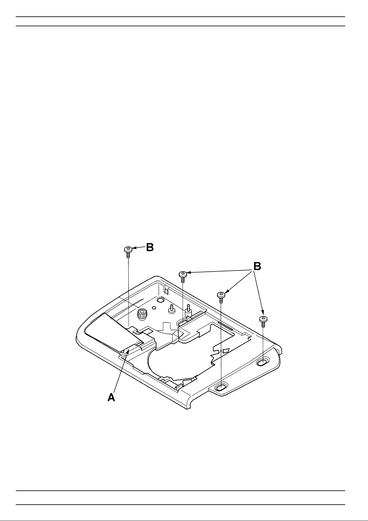
Dismantling and mounting
The hook cover compl, step motor house.
Dismounting
1. Dismount the rear covers and the front cover .
2. Move the presser bar to its highest position.
3. Remove the needle.
4. Dismount the presser foot holder.
5. Dismount the bobbin window, the stitch plate, the bobbin basket holder and the bobbin basket.
6. Snap away the thread cutter hatch by using a screwdriver at (A).
7. Dismount the 4 screws (B) on the hook cover and disconnect the step motor / lower thread indicator
cable from the main circuit board.
8. Dismount the hook cover by pulling it slightly backwards to the left.
Mount in reverse order
Set thereafter
13. Setting the stitchplate (hook cover )in relation to the needle in feeding direction.
14. The sideways setting of the stitchplate (hook cover ) in relation to the presserfoot.
15. The height of the hook.
17. Setting the feeding mechanism sideways.
74
104 72 53-26
Page 75
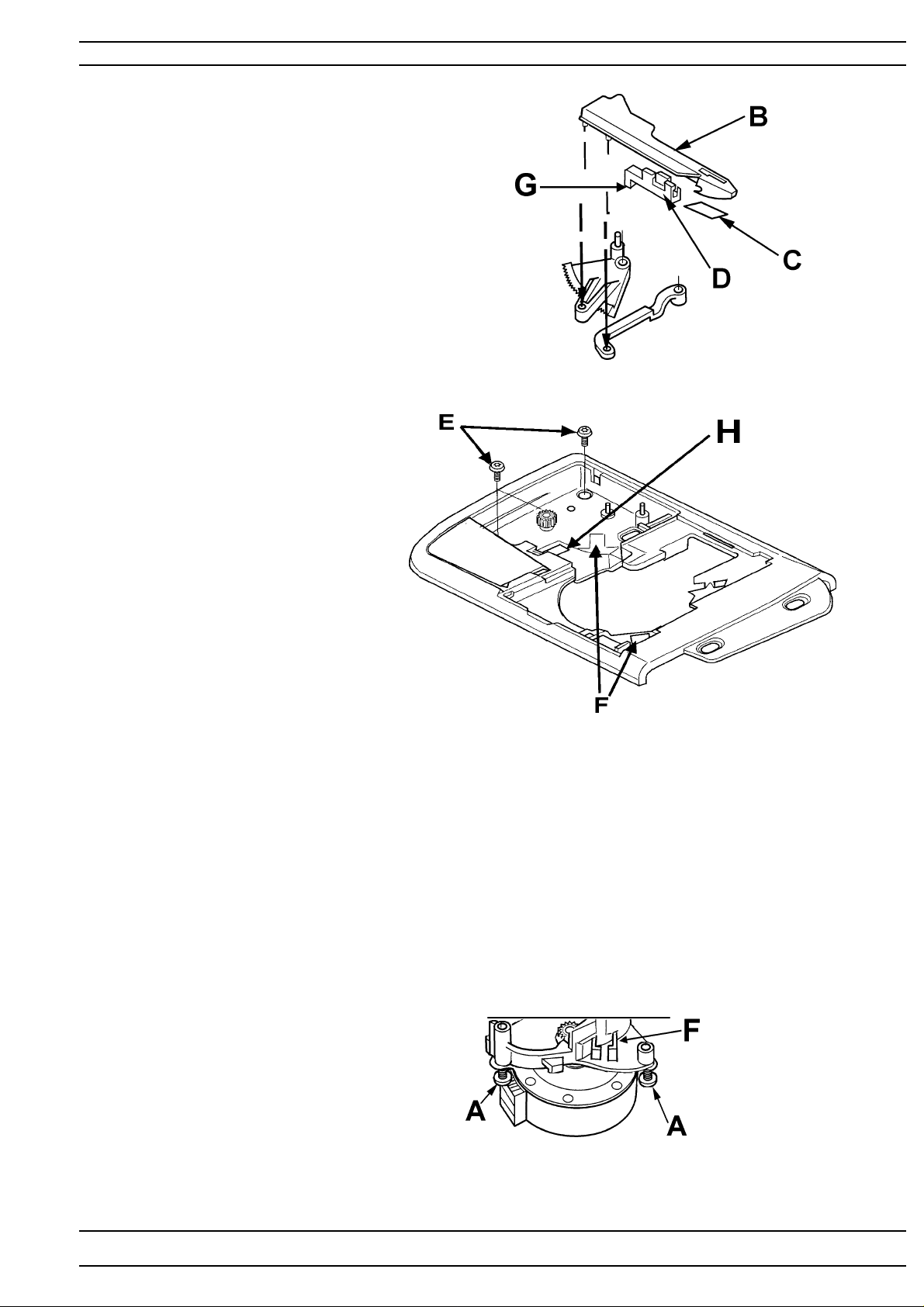
Dismantling and mounting
Parts of the hook cover compl.
- Designer I and Designer II
Changing the thread cutter knife
Dismounting
1. Dismount the stitchplate.
2. Snap away the thread cutter cover.
3. Dismount the thread cutter knife arm (B).
4. Dismount the thread cutter holder (D) .
5. Dismount the knife (C).
Mounting
Mounting in reversed order.
The pin (G) shall be in groove (H)
NOTE! When mounting the thread cutter knife arm check
that the thread brake lining isn't damaged.
The lower thread indicator
1. Dismount the hook cover.
2. Dismount the thread cutter step motor.
3. Snap away the thread cutter cover.
4. Dismount the thread cutter gearbox by removing the 2 screws (E).
5. Dismount the thread sensor complete. (F).
Mount in reverse order.
Note! Both diods on the thread
sensor should be pushed into
the hook cover.
The thread cutter step motor
Dismounting
1. Dismount rear covers and front cover
2. Dismount the hook cover complete.
3. Dismount the thread cutter step motor by
emoving the 2 screws (A).
4. Disconnect the cable from the step motor.
Mount in reverse order.
104 72 53-26
75
Page 76
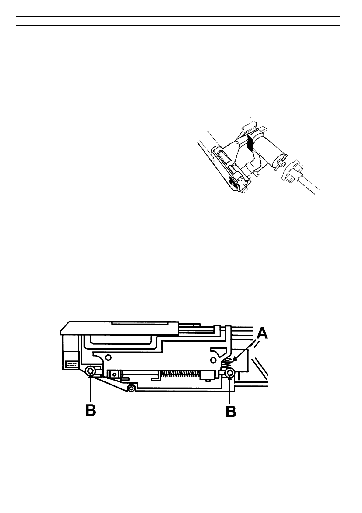
Dismantling and mounting
Feeding unit
Dismounting
1.Dismount rear and front covers.
2.Dismount the hook cover .
3.Dismount the needle and the presser foot holder and set the feeding eccentric straight backwards
(Needle in the highest position).
4.Unhook spring (A) from the feed carriage and disconnect the draw bar from the feed dog frame.
5.Dismount the 2 screws (B).
6 Disconnect the cross joint by pushing the feeding shaft to the right.
7.Lift out the complete feeding unit.
Mounting
1.Set feeding eccentric straight backwards.
2.Set the guide in the correct position see illustation.
3.Insert feeding unit and connect the cross joint.
4.Tighten screws (B).
5.Connect the draw bar and spring (A).
6.Mount hook cover, presser foot holder and needle.
Set there after
5.The setting of the feed unit sideways.
13.The setting of the stitch plate (hook cover) in relation to the
needle in the feeding direction
14.The sideways setting of the stitch plate (hook cover) in relation
to the presserfoot.
15.The height of the hook.
17.Setting the feeding mechanism sideways.
18.Feed dog height
20.Stitch length balance, basic setting
21.Pre-setting the feed dog step motor.
22.Stitch length balance, fine adjustment
76
104 72 53-26
Page 77
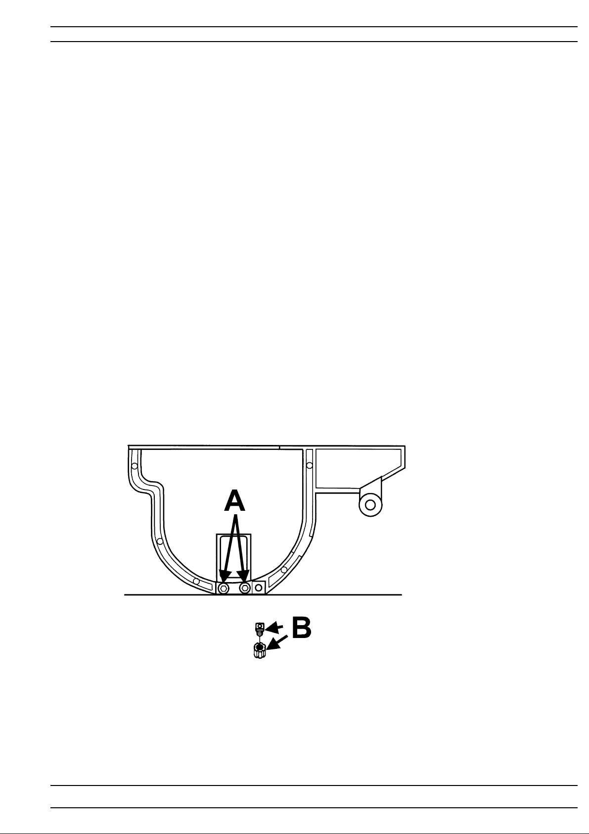
Dismantling and mounting
Feed dog.
Dismounting
1.Dismount the feeding unit.
2.Dismount the feed dog frame from the feed unit .
3.Dismount the feed dog by removing the 2 screws (A).
Mounting
1.Press the feed dog and the feed dog frame against a straight surface. See Fig 1.
2.Tighten the 2 screws (A).
3.Mount the feed dog frame on the feed unit
4.Mount the feed unit.
Set thereafter
5.The setting of the feed unit sideways.
13.The setting of the stitch plate (hook cover) in relation to the
needle in the feeding direction
14.The sideways setting of the stitch plate (hook cover) in relation
to the presserfoot.
18.Feed dog height
20.Stitch length balance, basic setting
21.Pre-setting the feed dog step motor.
22.Stitch length balance, fine adjustment
104 72 53-26
77
Page 78
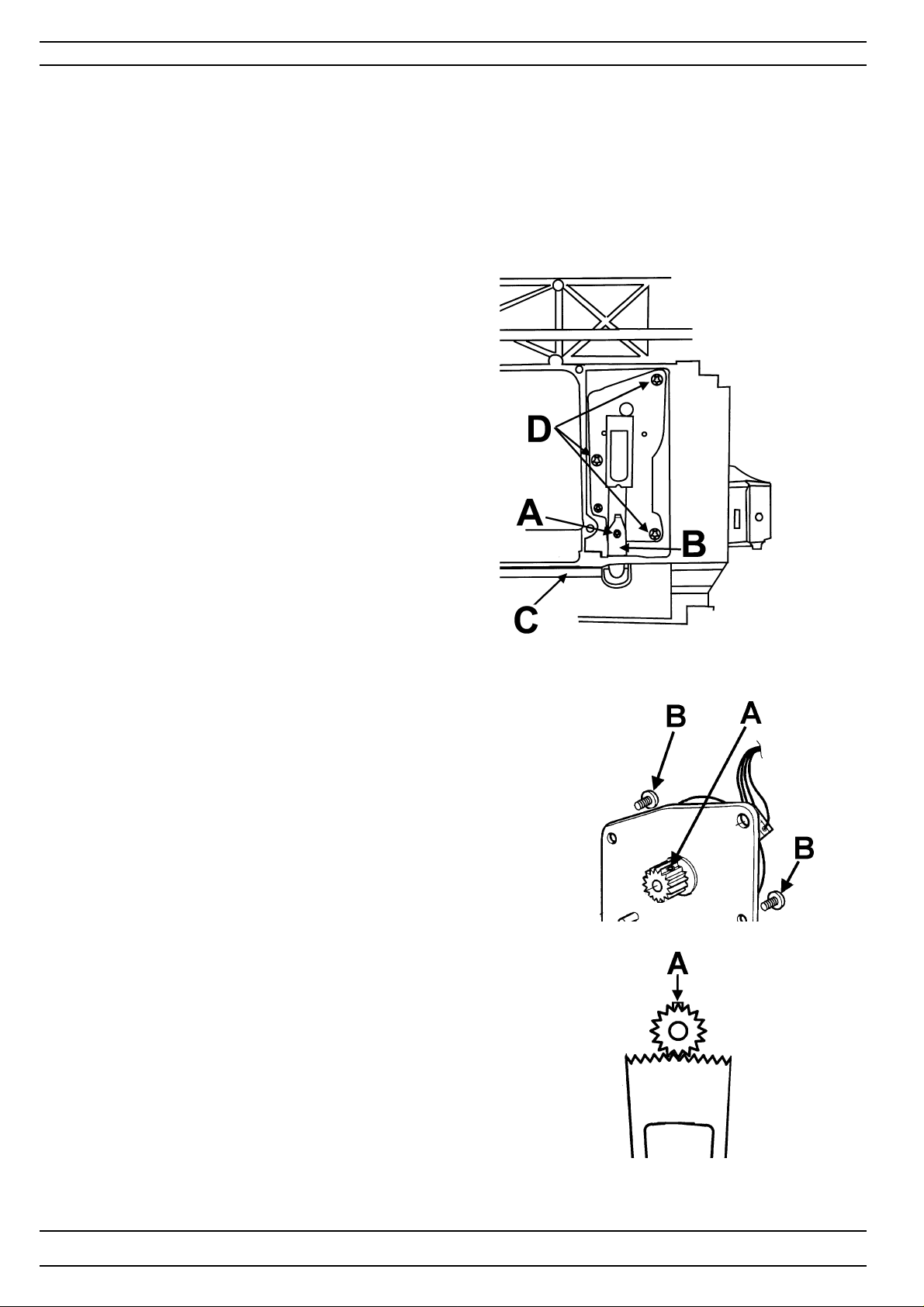
Dismantling and mounting
The side feeding mechanism complete
Dismounting
1. Dismount rear cover and front cover
2. Dismount the main circuit board
3. Disconnect the draw bar (C) from the side feeding mechanism by removing
the screw (A) and the clip (B).
4. Remove the 3 screws (D) and remove the side feeding mechanism.
Mount in the reverse order.
Set thereafter.
17. Setting the feeding mechanism sideways
22. The stitch length balance, fine adjustmemt.
The side feeding mechanism step motor
Dismounting
1. Dismount the side feeding mechanism .
2. Dismount the cogwheel by removing the screw (A)
3. Dismount the step motor by removing the 2 screws (B)
The step motor is connected to the circuit board according to
the wiring plan.
Mount in the reverse order.
Note! The screw (A) on the cog wheel shall be positioned so
it doesen't hit into the cog segment.
78
104 72 53-26
Page 79

Dismantling and mounting
The feeding unit step motor
Dismounting
1. Dismount rear cover and front cover.
2. Dismount the circuit board.
3. Dismount the base plate.
4. Unhook spring (A) at the end of the segment shaft.
5. Disconnect the draw bar from the side feeding mechanism.
5. Remove the screws (B) of the step motor frame, expose the cross joint (C)
between the step motor feeding shaft and the feeding unit by pushing
the shaft to the right.
6. Lift the step motor compl. out of the machine and remove its contact from
the circuit board.
Mounting
1. Position the step motor compl.
2. Connect the connection (C) between the segment shaft of the step motor
and the feeding unit.
Note! Location of the guide (see Fig 1 ). Do not turn 180 degrees wrong!.
3. Tighten screws (B) and connect contact to the circuit board.
4. Mount the spring holder and spring (A).
5. Mount the drawbar to the side feeding mechanism.
6. Mount the Base cover, main circuit board, front and rear covers
Set thereafter.
17. Setting the feeding mechanism sideways
20. Stitch length balance, basic setting
21. Pre-setting the feed dog step motor
22. Stitch length balance, fine adjustment
C
A
B
104 72 53-26
Fig 1
79
Page 80
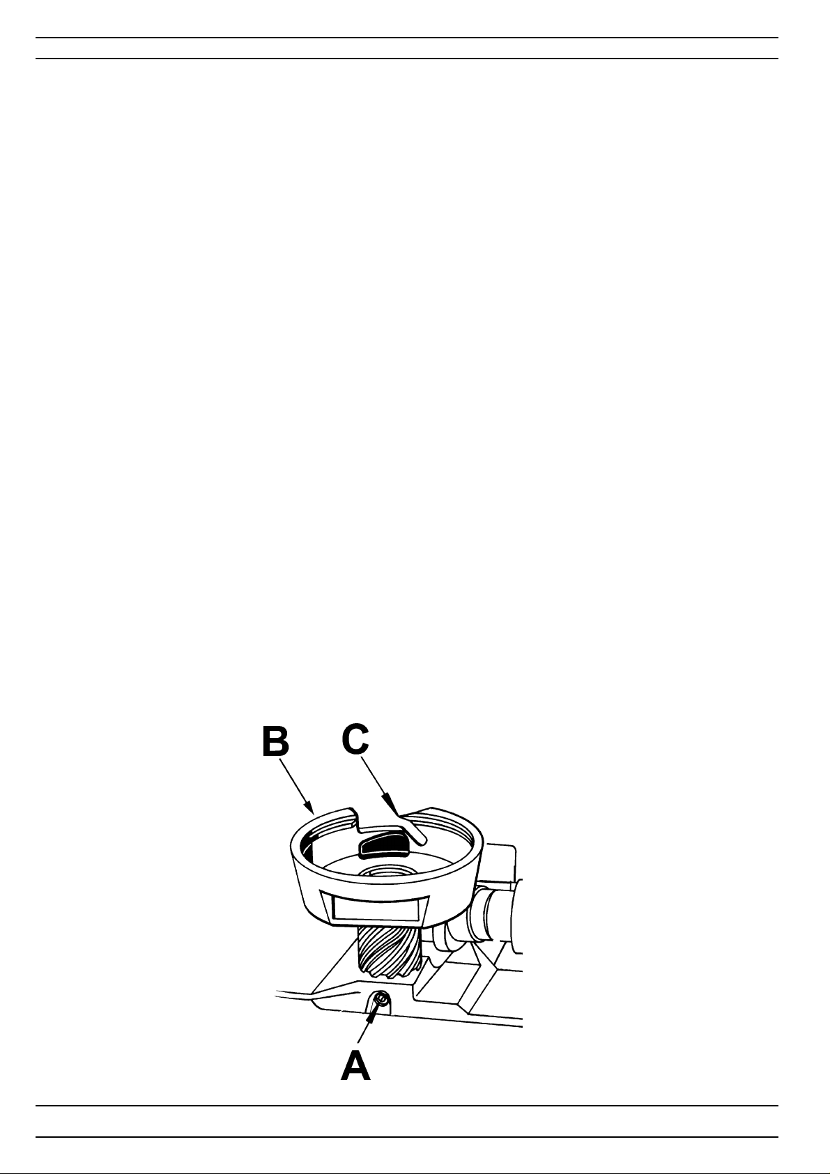
Dismantling and mounting
Hook compl.
Dismounting
1. Dismount rear cover and front cover .
2. Dismount the feeding unit .
3. Loosen the screw (A) and lift hook compl. (B).
Note! The hook can be dismounted without removing the feeding unit.
Mounting
1. Turn the hand wheel until the needle comes to its highest position.
2. Position washer, adjustment stud and dust shield onto the arm. W ith the adjustment
stud forward.
3. Place the hook so that the tip (C) points straight backwards.
4. Press the hook shaft downwards so that it is without play and tighten screw (A).
5. Mount the feeding unit.
Note! The position of the hook in relation to the lower shaft mustn’t be changed.
Set thereafter:
2.Setting of the hook in relation to the feeding eccentric.
1.Play of the hook gear.
5.Setting of the feeding unit sideways.
8.Gap between the needle and the hook.
9.Timing of the hook in relation to the needle.
10.Needle height.
13.The setting of the stitch plate (hook cover) in relation to the needle in the feeding direction.
14.The sideways setting of the stitch plate (hook cover) in relation
to the presserfoot.
15.The height of the hook.
18.Feed dog height.
22.Stitch length balance.
80
104 72 53-26
Page 81
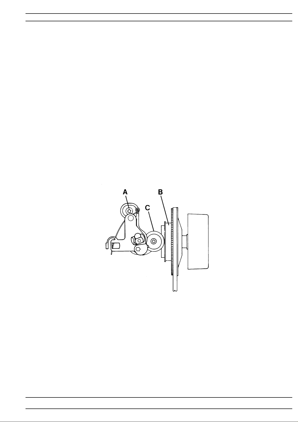
Dismantling and mounting
Bobbin winding device
Needle- and feeding movement should be disengaged when the ”bobbin
shaft with its rubber ring” is pushed against the ring (B), and engaged when
it is pushed back.
Dismounting
1. Dismount rear covers and front cover .
2. Dismount the screw (A).
Mounting
1. Keep the bobbin device in extended position.
2. Push ring (B) against the hand wheel.
3. Push the rubber ring (C) of the bobbin device against ring (B).
4. Tighten the screw .
5. Check.
Note! With the bobbin device in the extended position there should be a small
play when pushing the ring (B) against the hand wheel.
104 72 53-26
81
Page 82
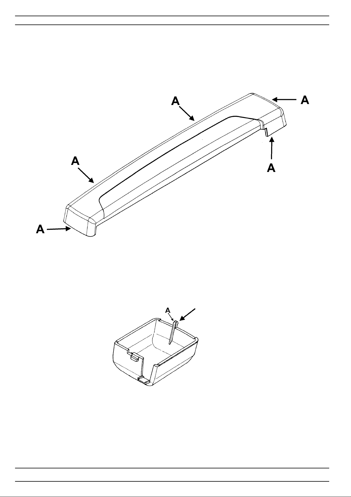
Embroidery Unit
Cover Y-slide
Dismounting
Cautiously bend the cover so that the 5 snaps (A) are exposed and lift the cover upwards.
Mounting
Place the cover over the plate and
press the snaps.
Step motor cover
Snap off the step motor cover by pushing in the snap (A) in the direction of the arrow .
82
104 72 53-26
Page 83
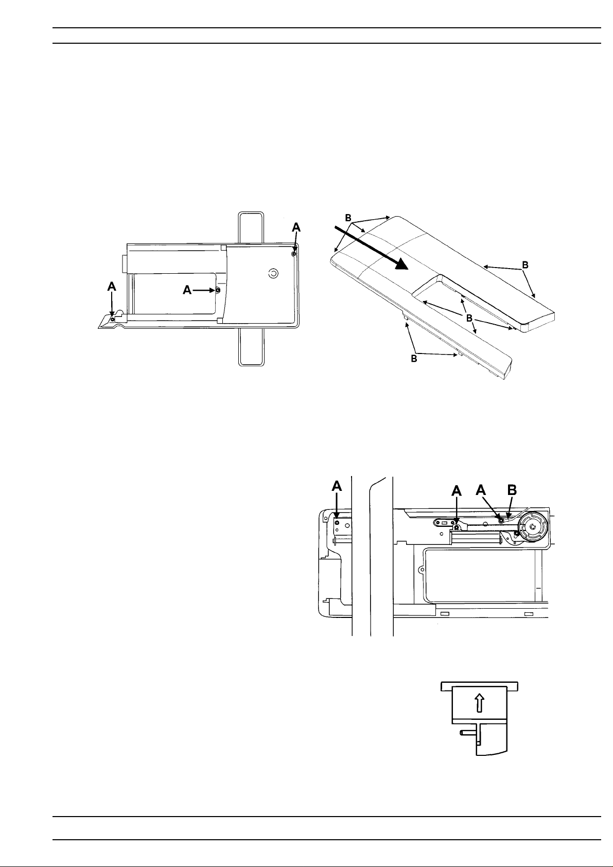
Embroidery Unit
Cover upper part
Dismounting
Move the Y-unit to its leftmost position
Remove the 3 screw's (A) underneath the lower cover.
Push the cover in the direction of the arrow to unhook the guides (B) from the embroidery unit.
Mounting in reversed order.
NOTE! Make sure that all guides (B) on the inside of the cover are correctly inserted.
Cover lower part
Dismounting
Remove the 3 screws (A) and grounding cable (B).
Lift out the embroidery and unhook the Y-unit from the guide rail.
Disconnect the cable to the step motor.
Detatch the connecting board and disconnect the cable.
Mounting in reversed order.
Locker switch
The locker switch contains a micro switch that shuts off the embroidery unit
when it is attached/detached from the machine.
Dismounting
Remove the upper cover
Push up the locker switch button and remove the micro switch.
104 72 53-26
83
Page 84
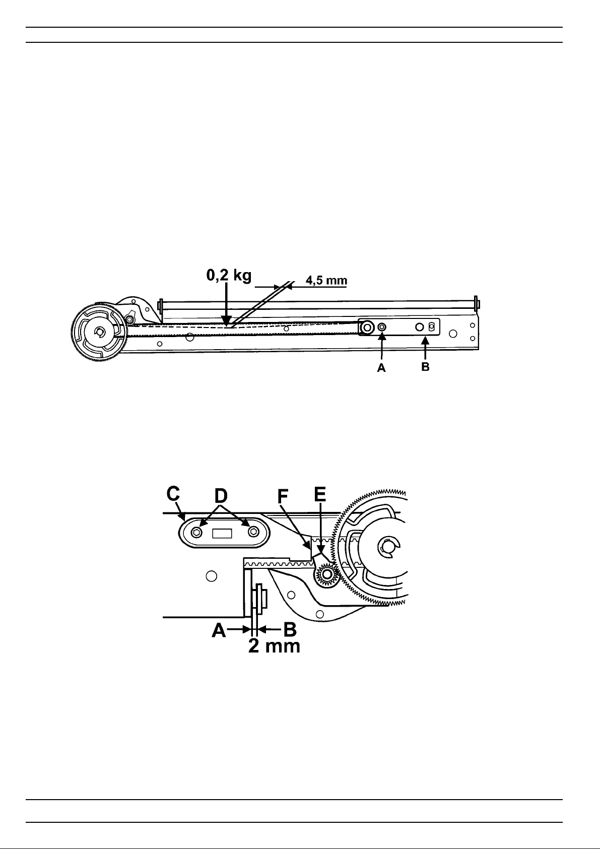
Embroidery Unit
Embroidery unit - X-unit
Belt tension
Check
The belt should be adjusted in such a way that it should be possible to
push in the belt approx. 4,5 mm with a force of 0,2 kg.
Adjustment
Adjust by loosening the screw (A) and move the plate (B) until a good
belt tension is obtained.
Calibration of the end position, X-unit.
Check
Move the X-unit to that the calibration stop (E) is against the frame (F).
The distance between (A) and (B) should now be 2 mm.
Adjustment
1. Remove the holder (C) by removing the screws (D).
2. Move the Y-unit so that the distance between (A) and (B) is 2 mm.
3. Turn the cog wheel so that the calibration stop (E) is against the frame (F).
4. Mount the holder (C) with one leg on each side of the belt.
5 Check
84
104 72 53-26
Page 85
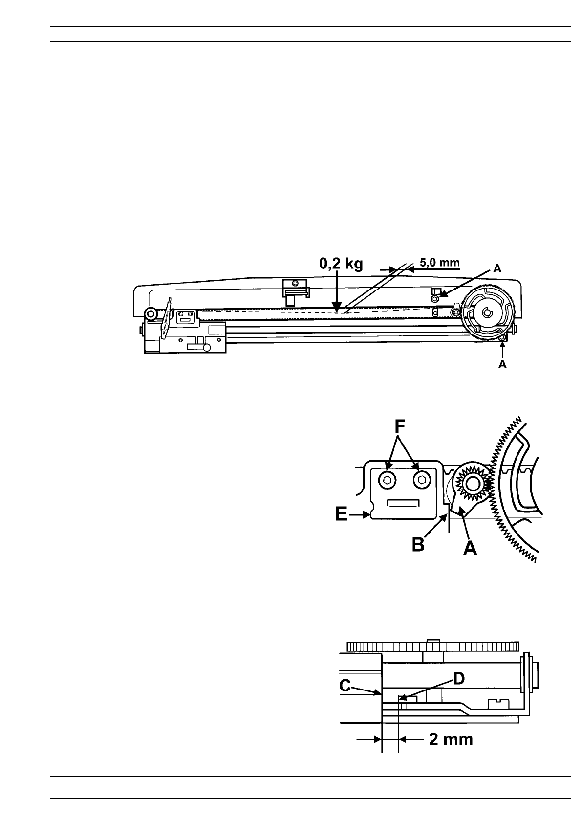
Embroidery Unit
Embroidery unit - Y-unit
Belt tension
Check
The belt should be adjusted in such a way that it should be possible to
push in the belt approx. 5 mm with a force of 0,2 kg.
Adjustment
Adjust by loosening the screw’s (A) and move the plate (B) until a good
belt tension is obtained.
Calibration of the end position, Y -unit.
Check
Move the Y-unit so that the calibration stop (A) is
against the hoop holder frame (B).
The distance between the hoop holder frame (C)
and frame stop (D) should be 2 mm.
Adjustment
1. Remove the holder (E) by removing the 2 screws (F).
2. Move the Y-unit so that the distance between (C)
and (D) is 2 mm.
3. Turn the cogwheel so that the calibration stop (A)
is against the frame(B).
4. Mount the holder (E) with one leg on each side of
the belt.
104 72 53-26
85
Page 86
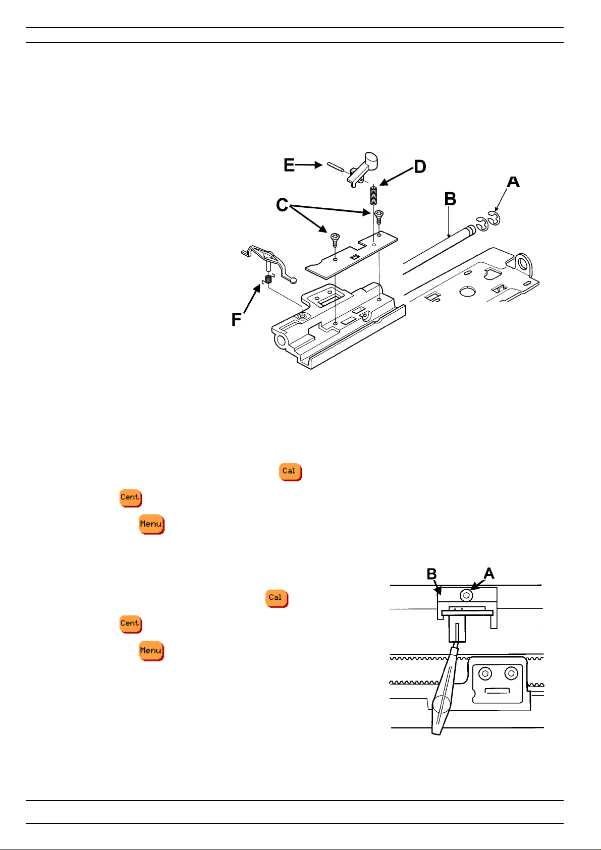
Embroidery Unit
Hoop holder
Dismounting
Remove locking washer (A), pull out the shaft (B) and remove the hoop holder .
Remove the two screws (C), pull out the spring (D) and remove the plate.
T o remove the button, push out the pin (E) from the backside.
T o remove the hoop sensor snap off the spring (F).
Mounting
Mount in reverse order.
NOTE ! After mounting
set calibration of the end position
The hoop sensor.
The embroidery unit has a sensor that indicates which hoop size that is inserted.
This is done by means of a photo-diode on the y-frame and a screen on the hoop holder.
Check
1. Mount the embroidery unit on the machine
2. Go to the service program, menu 1
3. Calibrate the embroidery unit by touching XY - , row 3.
4. T ouch XY - , row 3, the hoop now takes its center position.
5. T ouch Sensor- , row 3, the machine will now enter service menu 2 - sensor check.
6. The Hoop sensor square should now be activated=black, row 1 1.
Adjustment.
1. Go to the service program, menu 1
2. Calibrate the embroidery unit by touch XY - , row 3.
3. T ouch XY- , row 3, the hoop now takes its center position.
4. T ouch Sensor- , row 3, the machine will now enter
service menu 2 - sensor check.
5. Loosen the screw (A) and move the sensor holder (B) until
the hoop sensor square is activated=black, row 1 1.
6. Tighten the screw (A).
7. Re-check.
86
104 72 53-26
Page 87
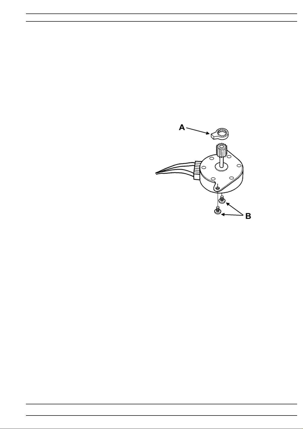
Embroidery Unit
Step motor, Y-unit
Dismounting
Dismount the Y -slide cover .
Dismount the step motor cover.
Dismount the upper cover.
Dismount the calibration stop (A) by pulling it up.
Dismount the cable from the connection board.
Dismount the step motor by removing the 2 screws (B).
Mounting in reversed order.
Set thereafter
Calibration of the end position, Y-unit.
The hoop sensor.
Step motor, X-unit
Dismounting
Dismount the upper cover.
Dismount the lower cover.
Dismount the calibration stop (A) by pulling it up.
Dismount the step motor cable.
Dismount the step motor by removing the 2 screws (B).
Mounting in reversed order.
Set thereafter
The calibration of the end position, X-unit.
104 72 53-26
87
Page 88

Fault finding diagram D I
Always update the flash memory to the latest version before doing any checking or adjustments,
even if the flash memory already is of the latest version!
The touch panel does not function.
1. Calibrate the touch panel.
2. Check the surface for damage.
3. Check that the cable is correctly inserted.
4. Try a new touch panel
5. Try a new main circuit board
The LCD has no background light
1. Check that the cables are correctly inserted. Try new cables.
2. Change the light tube transformer.
3. Try a new LCD.
4. Try a new main circuit board.
The floppy disk drive does not read or is not working at all.
1. Reset the machine.
2. Check with another floppy disk. If the machine reads that one, the first one was defective
3. Check that cables are correctly inserted. Try new cables.
4. If the machine does not read the second floppy disk try a new Floppy disk drive.
5. If the machine still does not read from the floppy disk try a new circuit board.
The floppy disk drive is reading but then stops and
The pop-up message “ No disk inserted ”, General disk fault” comes.
1. Check that it is an Husqvarna embroidery disk inserted.
2. Check the cables.
3. Try a new floppy disk drive.
4. Try a new circuit board
The buttons on the front panel does not function.
1. Check that none of the buttons on the machine are pressed in.
2. Check the contact area behind the buttons and the contact area on the push button boards.
3. Check that the guide boards are correctly assembled.
4. Check that cables are correctly inserted and not damaged.
5. Check the guide board for cracks in the lines and solders. Try a new push button board.
6. Try a new circuit board.
The LCD is not working at all or only partly.
(Shows wrong information, lines missing)
1. Check that the cable connections between LCD and circuit board are correctly inserted and not
damaged.
2. Try a new circuit board.
3. Try a new LCD.
The machine only runs at reduced speed.
If this occurs during service, check that the motor does not run in reverse.
1. Change motor.
2. Try a new circuit board.
The machine is completely dead. Motors and displays do not function.
1. Check the main cable.
2. Try a new transformer .
3. Try a new circuit board.
The machine does not work when the foot control is pressed, but works when pushing the start
button.
1. Check that the contact of the cord device of the cord is correctly pushed into the potentiometer .
2. Check by means of a new foot control (potentiometer, cord device).
3. Try a new transformer .
88
104 72 53-26
Page 89

Fault finding diagram
Fault finding diagram D II
Always update the flash memory to the latest version before doing any checking or adjustments,
even if the flash memory already is of the latest version!
The touch panel does not function.
1. Calibrate the touch panel.
2. Check the surface for damage.
3. Check that the cable is correctly inserted.
4. Try a new touch panel
5. Try a new LCDcircuit board
6. Try a new main circuit board.
The LCD has no background light
1. Check that the cables are correctly inserted.
2. Change the light module.
3. Try a new LCDcircuit board.
4. Try a new main circuit board.
The d-card drive does not read at all or is not reading correctly.
1. Reinsert the d-card and make sure that it is in correct position..
2.Reset the machine.
3. Check with another d-card, If the machine reads the new one the old was defective.
4. Check that cables are correctly inserted,also check that the two springs are correctly assembled.
5. If the machine does not read the second d-card try to change the memory connector board.
6. If the machine still does not read try a new circuit board.
The buttons on the front panel does not function.
1. Check that none of the buttons on the machine are pressed in.
2. Check the contact area behind the buttons and the contact area on the push button boards.
3. Check that the guide boards are correctly assembled.
4. Check that cables are correctly inserted and not damaged.
5. Check the guide board for cracks in the lines and solders. Try a new push button board.
6. Try a new circuit board.
The LCD is not working at all or only partly (wrong symbols or missing symbols)..
1. Check that the two cables from the LCD are corrctly pushed in to the connectors on the LCD circuit
board.
2. Try a new LCD.
3. Try a new LCD circuit board
The machine only runs at reduced speed.
If this occurs during service, check that the motor does not run in reverse.
1. Change motor.
2. Try a new circuit board.
The machine is completely dead. Motors and displays do not function.
1. Check the main cable.
2. Try a new transformer .
3. Try a new circuit board.
The machine does not work when the foot control is pressed, but works when pushing the start
button.
1. Check that the contact of the cord device of the cord is correctly pushed into the potentiometer .
2. Check by means of a new foot control (potentiometer, cord device).
3. Try a new transformer .
CContinuation
104 72 53-26
89
Page 90

Fault finding diagram
Fault finding diagram D I / DII
The machine does not start when neither foot control nor start button is pressed.
1. Check that the bobbin stop sensor is not activated.
2. Try a new motor.
3. Try a new circuit board.
The machine races when switched on or started.
1. Check that the start button does not stay pressed.
2. If the machine only races when the foot control is connected then check the foot control.
3. Try a new circuit board.
The zigzag movement of the machine does not work correctly.
1. Check that the twin needle isn’t activated.
2. Check in the service menu 2 that the arms shaft sensor is working.
If error - check first that the cable between sensor board and Main PC board is correctly inserted and not
damaged.
Still error , replace sensor board.
3. Check that the cable connection of the step motor to the circuit board is correctly inserted and not
damaged
4. Check the signals of the circuit board to the step motor.
If step motor is working – replace circuit board.
If step motor is not working - replace sewing head, complete.or step motor.
The feeding movement of the machine does not work correctly.
1.Check in the service menu 2 that the arm shaft sensor is working.
If error - check first that the cable between sensor board and Main PC board is correctly inserted and not
damaged.
Still error , replace sensor board.
2. Check that the cable connection of the step motor to the circuit board is correctly inserted and not
damaged
3. Check the signals of the circuit board to the step motor.
If step motor is working – replace circuit board.
If step motor is not working – replace step motor
The stitch length balance of the machine is not correct.
(Buttonholes, pattern stitches, letters)
1. Always use correct presser foot.
2. Check the pre-setting of the feeding step motor
3. Check that there is no friction in the feeding mechanism.
4. Adjust the stitch length balance.
The automatic thread tension does not work.
1. Check the cable connections between step motor and circuit board are correctly inserted and not
damaged.
2. Try a new step motor.
3. Try a new circuit board.
The machine does not alarm when the lower thread ends.
Before doing any service clean both diodes of the lower thread sensor and remove all fluff
1. Check the lower thread sensor in the service menu by rotating the hand wheel slowly
2. Check that cables to the circuit board are correctly inserted and not damaged.
3. Try a new lower thread sensor .
4. Try a new circuit board.
The thread cutter is not working
If the step motor is not working:
1. Check that the button is working.
90
104 72 53-26
Page 91

Fault finding diagram
Fault finding diagram D I / DII
2. Check that cables to the circuit board are correctly inserted and not damaged.
3. Try a new circuit board
4. Try a new step motor.
If the step motor is working but it is not cutting the thread:
1. Check that the thread cutter knife is positioned correctly .
2. Make sure the pickup is moving correctly .
3. Replace the knife.
The machine does not stop when the upper thread is finished or breaks.
Check the upper thread sensor in the service menu.
If OK:
1. Check the setting of the thread take-up spring and the thread tension.
2. Check the screens between the photo-diode of the upper thread guard so that it’s running smooth.
If not OK:
1. Check that the cable to the upper thread guard sensor board is correctly inserted and not damaged.
2. Try a new upper thread guard.
3. Try a new circuit board.
The machine stops and indicates that the upper thread is broken.
Check the upper thread sensor in the service menu.
If not OK:
1. Check that the sensor arm is correctly assembled on the spring
2. Check the setting of the thread take-up spring and the thread tension.
3. Check the screens between the photo-diode of the upper thread guard so that it’s running smooth.
If OK:
1. Check that the cable to the upper thread guard sensor board is correctly inserted and not damaged.
2. Try a new upper thread guard sensor board.
Try a new circuit board.
The presser foot lifter does not work.
Check in service menu that the presser foot sensors are working.
If OK:
1. Check if there is contact between the buttons and the push button board.
2. Check the cables from the step motor are correctly inserted and not damaged.
If not OK:
1. Try a new sensor or a complete sewing head.
2. Try a new sewing head slave board.
3. Try a new circuit board.
The buttonhole sensor does not work.
1. Make sure that the contact of the buttonhole sensor is correctly inserted and check its function by using
the service menu 2.
2. Try a new buttonhole sensor and check its function by using the service menu 2.
3. Check the cable from the contact of the buttonhole sensor to the slave board and the circuit board are
correctly inserted and not damaged.
4. Try a new sewing head slave board.
5. Try a new circuit board.
The side motion of the machine does not work at all.
1. Check the setting of the step motor of the side motion so that the screw does not get caught in the cog
segment.
2. Check the connection of the side feeding mechanism.
3. Check that the cable connection between the step motor and the circuit board are correctly inserted and
not damaged.
4. Try a new step motor.
5. Try a new circuit board.
104 72 53-26
91
Page 92

Fault finding diagram
Fault finding diagram D I / DII
The machine sews straight stitching only backwards.
If this occurs during service, check that the motor does not run in reverse.
1. Try a new circuit board.
The embroidery unit does not feed in all directions.
1. Check the calibration by using the service menu 1.
2. Check all cables of the embroidery unit are correctly inserted and not damaged.
3. Try a new motor.
4. Try a new circuit board.
The embroidery unit does not work at all.
1. Check the calibration by using the service menu 1.
2. Check that all cables in the embroidery unit are correctly inserted and not damaged.
3. Check the locker switch and cable.
4. Try a new circuit board.
5. Try a new step motors
The embroidery unit does not sew the pattern correctly
1. Check that there is no sluggishness or play in the embroidery unit.
2. Check the belt tension of the embroidery unit.
3. Check the calibration of the embroidery unit
4. Check so that the machine raises the presser foot to the correct height.
5. Check the thread tension of the machine.
The machine does not recognise the 240x150, 100x100 or150x360 embroidery hoops.
1. Check the sensor for hoop in the service menu 2.
2. Check the cable and its connections in the embroidery hoop.
3. Try a new sensor.
92
104 72 53-26
 Loading...