

Page 1

For Husqvarna Parts Call 606-678-9623 or 606-561-4983
6.5HP/19"
t
i
n
a
g
t
o
T
R
i
n
l
a
u
D
www.mymowerparts.com
e
s
Page 2

For Husqvarna Parts Call 606-678-9623 or 606-561-4983
Table of Contents
Page
1999 Changes for Tillers 2
Rear Tine Tiller Transmission Replacement 3 - 4
1999 Changes for Lawn Tractors 5 - 6
1999 Change for Garden Tractors 6
New Lawn Tractor Neutral Adjustment 7
Operator Presence System ‘C’ change 8
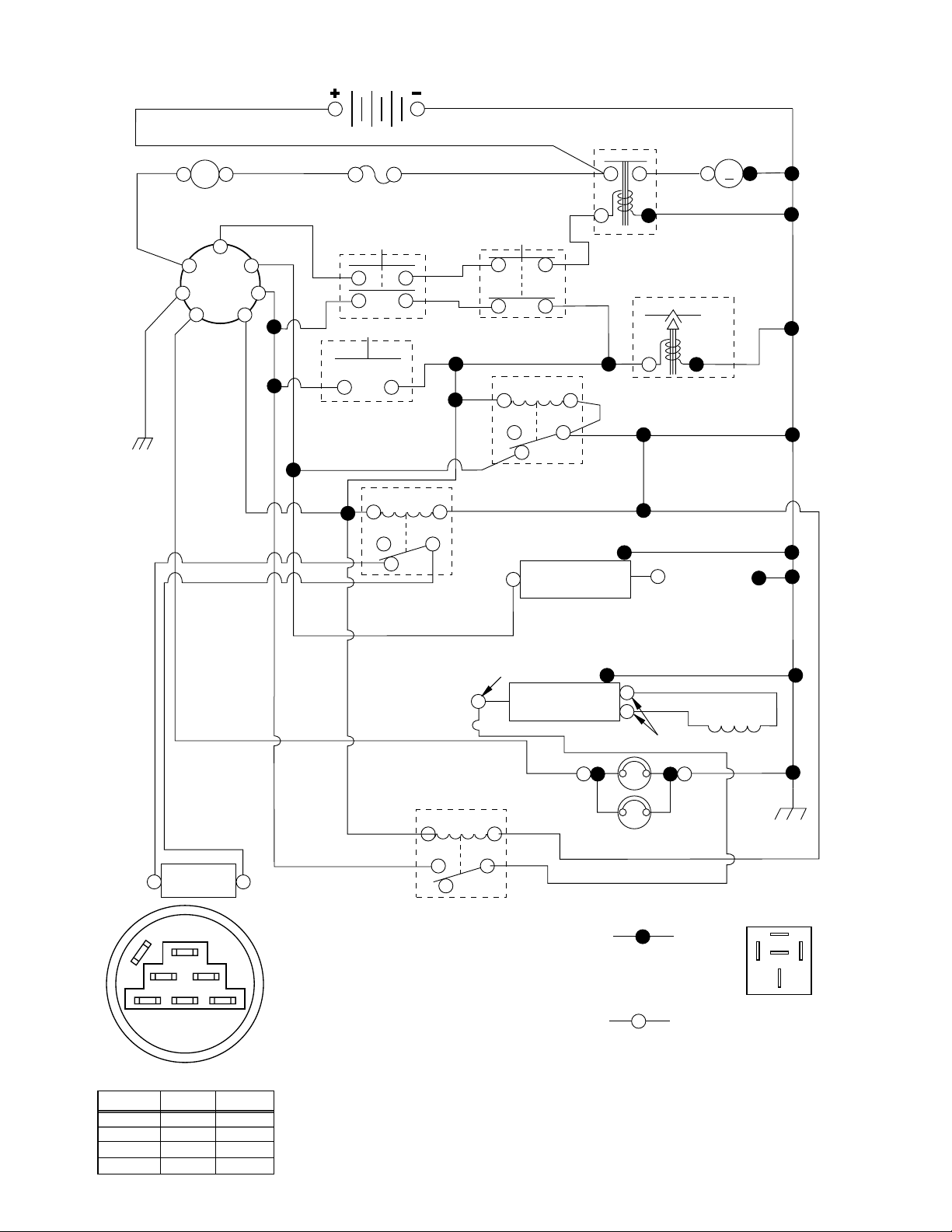
Operator Presence System ‘C’ Schematic Example 9
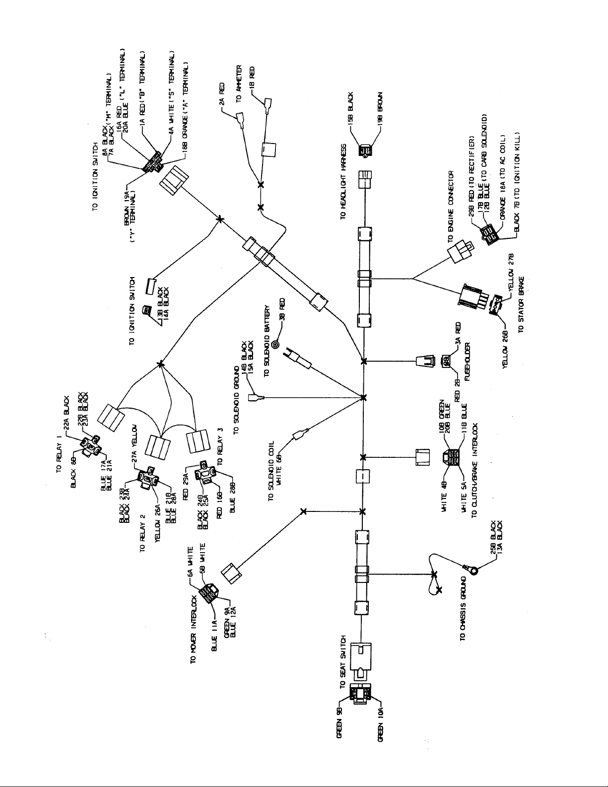
Operator Presence System ‘C’ Harness Print Example 10
1999 Changes for Tractor Electrical Systems 11
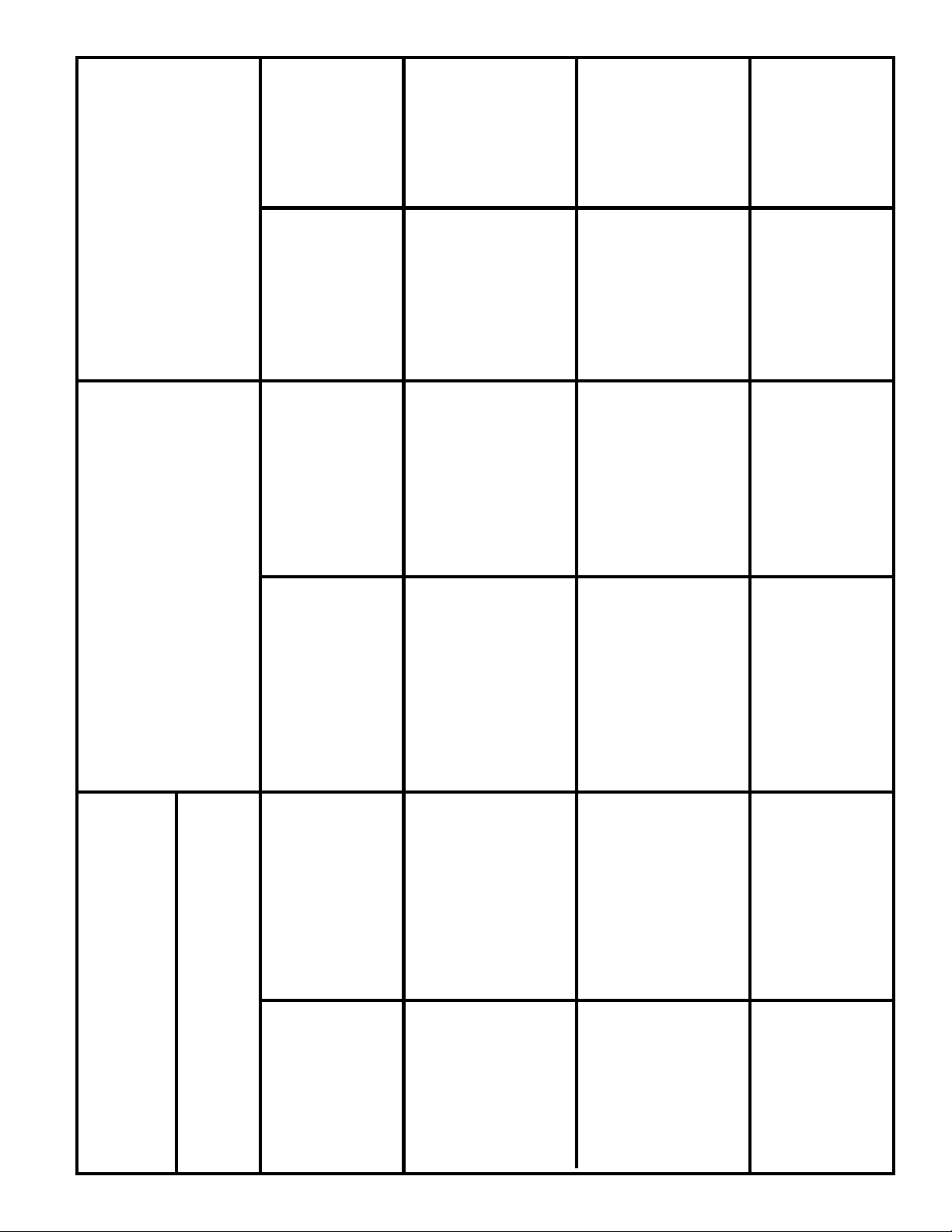
Electrical Parts Reference 12
1999 Changes for Tractor Mowers 13
Mower Blade Listing 14
New in Rotary Mowers for 1999 15
21” 10 Speed Rear Drive Gearbox Replacement 16 - 19
21” 10 Speed Rear Drive – Belt Replacement Procedure 20
Touch - Up Paints 21
Tire Sealants 22
Part No.168830
1
www.mymowerparts.com
Page 3

For Husqvarna Parts Call 606-678-9623 or 606-561-4983
1999 Changes for Tillers
New for 1999 is a DRT Tiller. DRT stands for Dual Rotation Tines. The tines can be
shifted for movement as Counter Rotating Tines or Standard Rotating Tines. CRT
operation is best for breaking ground and preparing a plantable seadbed. SRT
operation is best for cultivating and composting plant material into the ground. The
tines for CRT Tillers and DRT Tillers are very different. The DRT Tine assembly is
shown on the Right.
CRT Tines
DRT Depth Stakes
1986-1998 CRT Belt Guard & Hardware
DRT Tines
DRT tillers will have two rear stakes. The depth
stake used for counter rotating tines must be raised
when tines are in standard rotation; or the tines will
not contact the ground. When using the tiller with
counter rotating tines, the depth stake should be
adjusted down for the desired tilling depth, and the
drag stake fully raised. If the drag stake is down in
CRT mode, difficult handling characteristics may be
experienced.
1999 DRT Belt Cover & Inner Shield
1980-1998 Belt Guard & Hardware (FT)
www.mymowerparts.com
1999 Belt Cover & Inner Shield (FT)
2
Page 4

For Husqvarna Parts Call 606-678-9623 or 606-561-4983
Rear Tine Tiller Transmission Replacement
Teardown CRT Tiller:
1. Remove both front Counter Weights.
2. Remove right side Outer Shield and Side Shield.
3. Remove the right Tine Assembly.
4. Remove right Wheel Assembly.
5. Remove all bolts that hold right side of Tine Shield to the transmission.
6. Remove right side engine Bolts, remove engine Reinforcement Bracket, and
disconnect Throttle Cable from engine.
7. Remove the Nut and Lock Washer that holds Idler Arm Shaft on the transmission .
8. Remove control cable Clamp from the transmission and transfer to the new transmission.
9. Change to the left side of the tiller. Remove the Outer Shield and Side Shield.
10. Remove the left the Tine Assembly.
11. Remove left Wheel Assembly.
12. Remove one Bolt that holds the Latch Bracket Assembly to the transmission.
13. Remove the Bolt at the top of Depth Stake and remove the Depth Stake.
14. Remove all bolts holding Tine Shield on left side of the transmission.
15. Remove the Belt Guard.
16. Disconnect the Control Cable from the idler bracket. Remove the Idler Arm
Bracket with Pulley and Idler Arm Shaft as a complete Assembly.
17. Remove the Pulley from transmission.
18. Remove left side engine Bolts, remove Engine and Engine Reinforcement
Bracket from the transmission.
19. Remove Shift Indicator, Shift Rod and remove Handle Assembly from
transmission.
20. Remove the long Bolt that holds the top rear of belt guard to the transmission
and install on new transmission.
Instructions are from Standing at the operating position of the tiller .
On DRT models, remove both depth stakes at the same time.
3
www.mymowerparts.com
Page 5

For Husqvarna Parts Call 606-678-9623 or 606-561-4983
Rear Tine Tiller Transmission Replacement
Assemble Tiller
1. Install Engine and engine Reinforcement Brackets on transmission and
tighten all bolts.
2. Install Counter Weight onto transmission and tighten bolts.
3. Install Idler Bracket Assembly to the transmission and tighten.
4. Install Transmission Pulley and route V-Belt around transmission pulley and
engine pulley.
5. Install Handle Assembly, hook up Control Cable to idler bracket , install Shift
Indicator and Shift Rod to shift lever and hook up Throttle Control.
Adjust Control Cable Spring for 5/8” stretch.
6. Add top rear belt guard Bolt and Spacers, put long Spacer on first, then add
Pinch Guard, then the Short Spacer and Washer. Place the spacer and
washer onto the rear lower belt guard bolt.
7. Install Belt Guard add Flat Washer and Cap Nut to front and top back studs,
at bottom of belt guard use flat washer and regular nut.
8. Install Tine Shield and front Tines Shield Brackets as an assembly. Place
all bolts and nuts before tightening.
9. Install right and left Tine Assembles. Use recommended Shear Pins.
10. Install right and left inner Side Shields and tighten nuts.
11. Install right and left outer Side Shields.
12. Install both Wheel Assembles.
13. Lift up and slide Depth Stake into slot in transmission. Secure Depth Stake
with Bolt, Nut, and Rubber Tip. Adjust to lowest position.
On DRT models, install both depth stakes at the same time.
4
www.mymowerparts.com
Page 6

For Husqvarna Parts Call 606-678-9623 or 606-561-4983
1999 Changes for Lawn Tractors
1999 Tapered Pivot Bearing & Sleeve
The front axle Pivot Bearing has had a
taper added. This will keep the pivot
bearing tighter in the front axle. The
new part will automatically sub for the
old pivot bearing. More effort will be
needed to assemble the tapered pivot
bearing into the front axle.
167118
1997 Drive Belt Idler Pivot - 7 pieces
Hex Bolt
Spacer
Nut
3/8”X16
1988-1998 Transaxle Belt Guides on Chassis
74760624
Nylon
Liners
1999 Drive Belt Idler Pivot - 4 pieces
Carriage Bolt
72110626
165850
19133210
Nut
3/8”X16
1999 Transaxle Belt Guides on Peerless Transaxle
Belt
Guide
Belt
Guide
Belt
Guide
5
www.mymowerparts.com
Page 7

For Husqvarna Parts Call 606-678-9623 or 606-561-4983
1999 Changes for Lawn Tractors
1989-1998 Steering Shaft Support
Shaft Support
Screw
Steering Assembly 1989 - 1998
1999 Steering Shaft Support
160395
165957
1999 Steering Assembly
160395
Pittman
Shaft
Clip Ring
At the end of the pittman shaft, a bolt and washer replace the clip ring.
1999 Garden Tractor Change
A Garden Tractor Lift Shaft change
will make assembly easier. Previous models had a splined lift shaft end. One spline
was missing so the lift shaft and lift lever
would be aligned. During 1998 a double
‘D’ shaft end was introduced providing
alignment and easier assembly.
165852
74950612
19132012
Spline Shaft
6
www.mymowerparts.com
Page 8

For Husqvarna Parts Call 606-678-9623 or 606-561-4983
NEUTRAL ADJUSTMENT FOR AUTOMATIC DRIVE CONTROL LEVER
1. Place the tractor on a smooth paved level surface.
2. Loosen Adjustment Bolt in front of the right rear wheel, and lightly tighten using a 1/2" wrench.
3. Start Engine and move Lever until tractor does not move forward or backward.
Hold Control Lever in that position and do not move. Turn the engine off.
4. While holding the Control Lever to keep it from moving, loosen theAdjustment Bolt . Move the
Control Lever to the position indicated for Neutral on the fender. Tighten Adjustment Bolt
securely .
FINE TUNE THE NEUTRAL ADJUSTMENT ON AUTOMATIC DRIVE
1. Place the tractor on a smooth paved level surface.
2. Loosen the Adjustment Bolt using a 1/2" wrench. If the tractor is creeping forward, move the
Control Lever forward 1/4 to 1/2 inch. Move the Control Lever rearward 1/4 to 1/2 inch if the
tractor is creeping backwards. Tighten the Adjustment Bolt securely.
3. Start engine and test from both forward and reverse.
4. If tractor still creeps, repeat step # 2 until satisfied.
NOTE: If additional clearance is needed to get to adjustment bolt, move mower deck height to the
lowest position.
NEUTRAL ADJUSTMENT FOR GEAR DRIVE SHIFT LEVER
1. Place the tractor on a level surface.
2. With the engine off and the parking brake disengaged, push the tractor from behind while shifting
gears.When the tractor rear wheels move freely, the transaxle is in neutral. Leave in this position.
3. Loosen Adjustment Bolt in front of the right rear wheel,using a 1/2" wrench. Position the Lever
in the position indicated for Neutral.Tighten Adjustment Bolt securely.
NOTE: If additional clearance is needed to get to adjustment bolt, move mower deck height to the
lowest position.
7
www.mymowerparts.com
Page 9

For Husqvarna Parts Call 606-678-9623 or 606-561-4983
OPERATOR PRESENCE SYSTEM
The Operator Presence System is designed to protect the operator of the tractor.
This system will short the ignition system for the engine to die and the mower blades to stop.
When the operator is in the ‘safe’ position the tractor and mower will work.
Tractors have had an Operator Presence System since 1987. New ANSI standards went into
effect on July 1, 1997 that makes it mandatory for the engine and mower blade to stop in
five (5) seconds or less. For clarity in this discussion, we will label these systems with letters. System ‘A’ will
be used on tractors with a manual mower clutch unless that tractor has a
KOHLER Command single cylinder engine.
System ‘B’ will be used on most Source 917 tractors with an Electric Clutch for mower engagement and a
Magneto Ignition. This system will have one (1) relay in the operator presence circuit.
There have been changes to System ‘C’ during 1998. Below find a rewritten explanation for System
‘C’ along with a new schematic and new harness print for Ignition Harness # 163845. For the complete
explanation of all 5 Operator Presence Systems, see the 1998 FHP On-Site Manual number 163578.
OPERATOR PRESENCE SYSTEM ‘C’
System ‘C’ will be used on Source 917 tractors with a Kohler Command Single Cylinder engine and manual
mower engagement on a 42” Mower deck.
In this system electrical current flows from the Ignition Switch through either the Seat Switch (NO) or the
Clutch/Brake and Attachment Switches to energize two Operator Presence Relays. Operator Presence Relay
#1 when de-energized grounds the ignition to stop the engine. Operator Presence Relay #2 when de-energized connects to short-circuit the engine alternator stator. The shorted stator creates the maximum potential
opposition to the charging magnets. The increased drag of the charging system helps oppose the flywheel
momentum and stop the engine faster. This is a Stator Brake.
There is a Stator Brake with the 5 Amp charging system with two relays in the harness.
There is a different Stator Brake with the 15 Amp charging system with three relays in the harness. With the
15 Amp system, Relay #3 disconnects the charging system from the tractor. This directs all the current from
the alternator to the Stator Brake.
In this system the Seat Switch is Olive Green and normally open when the operator is off the seat. The
operator may actuate the Operator Presence Relay two ways:
● Both the Clutch/Brake and Attachment Interlock Switches are closed in the safe position,
● The operator is on the seat closing the Seat Switch.
When either of these conditions are met and the Ignition Switch is in the ‘Start’, ‘Run’, or the ‘Run and Lights’
position:
● Operator Presence Relay #1 is energized opening the contacts that otherwise would “kill” the ignition,
● Operator Presence Relay #2 is energized opening the contact that normally engages the “Stator Brake”,
● The Stator Brake, a magnetic field brake, is actuated.
● The Fuel Shut-off Solenoid is energized letting fuel into the carburetor. This circuit also supplies
current to the S.A.M. on Kohler Command Engines with this ignition system.
Operator Presence Relay # 3 disconnects the engine charging system from the tractor.
8
www.mymowerparts.com
Page 10
For Husqvarna Parts Call 606-678-9623 or 606-561-4983
Harness #163845 Operator Presence System ‘C‘
AMMETER
(OPTIONAL)
RED
BLACK
A
S
B
G
IGNITION
SWITCH
M
AY
RED
WHITE
L
ORANGE
BLACK
BATTERY
FUSE 30 AMP.
CLUTCH / BRAKE
(PEDAL UP)
BLUE
GREEN
SEAT SWITCH
(NOT OCCUPIED)
BLACK
85 86
87
YELLOW
YELLOW
PRESENCE RELAY #2
WHITE
BLUE
GREEN
30
87A
OPERATOR
BLACK
BLACK
REDRED
ATT'MENT CLUTCH
(CLUTCH OFF)
BLUE
85 86
BLUE
87
BLUE
PRESENCE RELAY #1
87A
OPERATOR
WHITE
BLUE
30
IGNITION
UNIT
SOLENOID
FUEL SHUT-OFF
M
STARTER
BLACK
FUEL
LINE
SOLENOID
SPARK
PLUG
GAP
(2 PLUGS ON
TWIN CYL. ENGINES)
BROWN
STATOR
BRAKE
A
G
Y
ML
IGNITION SWITCH
CIRCUITPOSITION
OFF
G + M + L
B + LRUN/LIGHT
B + LRUN
B + L + SSTART
S
B
“MAKE”
NONE
A + Y
NONE
NONE
OPERATOR
PRESENCE RELAY #3
BLUE
RED
85 86
87
87A
WIRING INSULATED CLIPS
NOTE: IF WIRING INSULATED
CLIPS WERE REMOVED FOR
SERVICING OF UNIT, THEY
SHOULD BE REPLACED TO
PROPERLY SECURE YOUR
WIRING.
9
CHARGING SYSTEM OUTPUT
15 AMP DC @ 3600 RPM
REGULATOR
BROWN
BLACK
30
YELLOW
ALTERNATOR
28 VOLTS AC @ 3600 RPM
(REGULATOR DISCONNECTED)
HEADLIGHTS
RED
NON-REMOVABLE
CONNECTIONS
REMOVABLE
CONNECTIONS
BLACK
87
87A
30
RELAY
8586
www.mymowerparts.com
Page 11
For Husqvarna Parts Call 606-678-9623 or 606-561-4983
Harness #163845 Operator Presence System ‘C‘
10
www.mymowerparts.com
Page 12
For Husqvarna Parts Call 606-678-9623 or 606-561-4983
1999 Changes for Tractor Electrical Systems
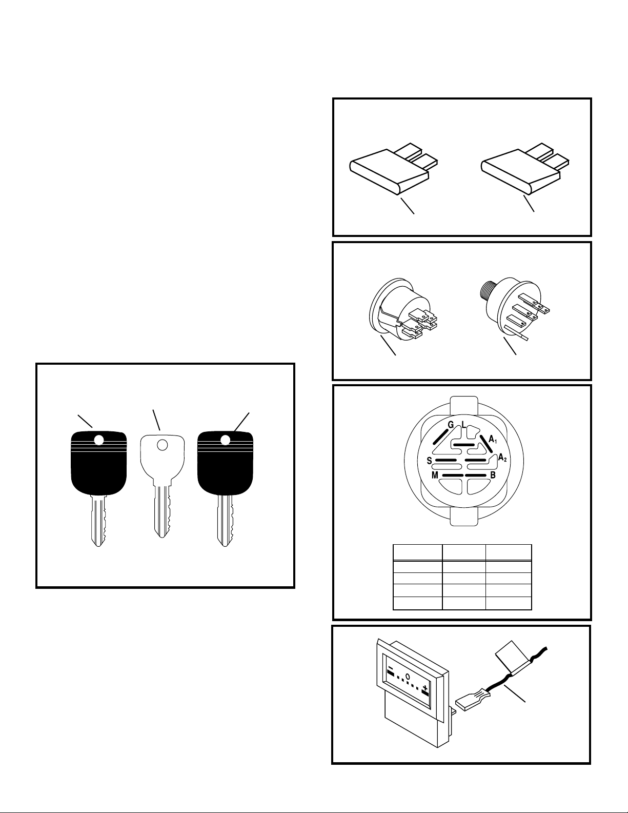
A 15 Amp Fuse is used on 1999
Lawn Tractors. Lawn Tractors made
before 1999 can use either the 15 Amp or
30 Amp fuse. All Garden Tractors should
use the 30 Amp fuse.
A new snap in ignition switch #
163968 came into use during 1998 production. It was first used with the new GT
Stealth aesthetic package. This ignition
switch will be added to other aesthetic
packages and on most FHP tractors by
the year 2000.
When the snap in ignition switch is
used the longer ignition key must be used.
15
15 Amp Fuse
30
30 Amp Fuse
Ignition Key
140401
Generic
140402
CRAFTSMAN
140403
Craftsman
FHP wire harnesses have had red tape
on the red wire from the battery. In 1999
this will change to a white tape with a red
( + ). This will make the wire easier to find
and will better explain the purpose of the
tape. If the wires to the ammeter are
reversed it will read in reverse (discharging when charging).
New Ignition Switch
IGNITION SWITCH
OFF
D.C. AMPERES
Old Ignition Switch
CIRCUITPOSITION
M+G+A1
B+A1RUN/LIGHT
B+A1RUN
B + S + A1START
“MAKE”
NONE
A2+L
NONE
NONE
(+)
Red
11
www.mymowerparts.com
Page 13
For Husqvarna Parts Call 606-678-9623 or 606-561-4983
Electrical parts reference, see manual 163578 page 60 for legends of ignition switches
Seat Switch
121305X
Jumper Kit 150834
NC Gray
Black/Gray
lnterlock Switch
NO / NO snap-in
161343
generic cover
Ignition Key
140401
(delta)
screws
Ignition Switch
std 365401
NO - Olive Green
Seat Switch
160784-
Terminal Connector Kit 148691
Hourmeter
110940X
(hourmeter)
Wire Loop
141940
lnterlock Switch
NO / NC snap-in
153664
Gray
lnterlock Switch
NO / NC screw
109553X
Gray
lnterlock Switch
NC / screw
109869X
Gray
bright finish
Craftman cover
generic cover
Ignition Key
140402
(delta)
Ignition Key
140403
(delta)
Ignition Key
122147X
(indak)
Ignition Switch
std 365402
5 terminals
4406R
(Battery Ignition)
Ignition Switch
5 terminals
2683R
Ignition Switch
7 terminals
140301-
Solenoid Kit146154
Solenoid 144673
140844-
Relay 109748X
122822X
www.mymowerparts.com
Jumper Wire
(ammeter)
Ammeter
lnterlock Switch
NO Screw
104445X
PTO Switch
154963
12
Craftman cover
(bulb 7152J)
Ignition Key
109310X
(indak)
Headlight Socket
Stealth Hood only
163996
5 terminals
158913-
7 terminals
snap - in
163968-
Ignition Switch
Ignition Switch
Page 14
For Husqvarna Parts Call 606-678-9623 or 606-561-4983
1999 Changes for Tractor Mowers
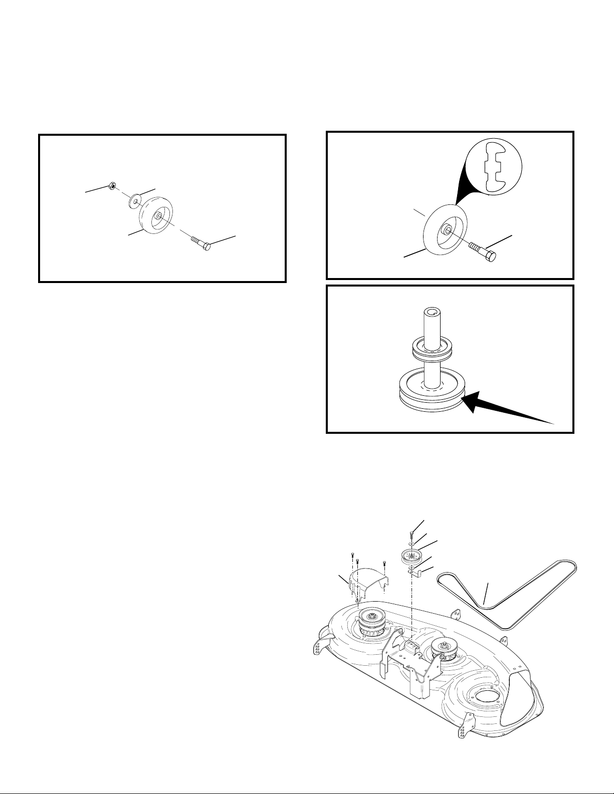
New Gauge wheels will allow tractors with twin blade mowers to be shipped with gauge
wheels assembled. The wider gauge wheels will continue to be used on three blade
mowers.
Guage Wheel
Washer
3/8 X 7/8
Locknut
3/8 X 16
133957
137644
The engine stack pulley has been
improved for 1999. The pulley for the
mower belt now has a different contour
to better allow for the range of belt
movement for the mower deck.
New Gauge Wheel
4898H
165746
New Double Lead Pulley
Primary V-Belt Kit for 46” Deck With Electric Clutch
Kit #166109
1. Remove the LH Deck Mandrel Cover, 145059 and the
current Primary Mower V-Belt, 139573 from the deck.
Discard the
v-belt.
2. Remove the primary Drive Idler Pulley, 156493 and
the Threadroll Screw, 17490628.
3. Install the Spacer Washer, 19132203, between the
Primary Drive Idler Pulley, 156493, and the Idler Belt
Keeper, 156086. Hold belt keeper in place as
Threadroll Screw, 17490628 is tightened to ensure
correct orientation of the belt keeper.
4. Route the new Primary Mower V-Belt, 148763, in the
same path as the old Primary Mower V-Belt, 139573.
5. Install the LH Deck Mandrel Cover, 145059 back on
the deck with the original hardware. Installation is
complete.
NOTE: 46” manual engagement mower deck uses primary belt #158818.
145059
17490628
19131616
156493
19132203
156086
148763
13
www.mymowerparts.com
Page 15

For Husqvarna Parts Call 606-678-9623 or 606-561-4983
* BLADE LISTING *
by RETAINER HOLE CHARACTERISTICS
PART DECK CONSTRUC- TYPE DECK HOLE(S) BLADE RETAIL
NUMBER SIZE TION TYPE BOLT(S) NUMBER
145106 20" REGULAR MULCH 3 1 71-33255
146749 20" PREMIUM MULCH 3 1 71-33271
701211 20" PREMIUM STANDARD 3 1 71-33270
850972 20" REGULAR STANDARD 3 1 71-33233
154208 20" ELECTRIC MULCH CAST DECK 31
156716 20" ELECTRIC MULCH REAR DISCHARGE 31
159267 21" REGULAR MULCH REAR DRIVE 3 1 71-33273
161541 21" REGULAR STANDARD REAR DRIVE 31
165833 21" REGULAR MULCH PUSH 3 1 71-33274
152202 22" REGULAR MULCH SIDE DISC EZ3 31
157101 22" REGULAR MULCH REAR DISCHARGE 3 1 71-33269
141 114 22" REGULAR MULCH 3 1 71-33256
141443 22" PREMIUM MULCH 3 1 71-33272
701213 22" PREMIUM STANDARD 3 1 71-33223
850973 22" REGULAR STANDARD 3 1 71-33234
25645 36" REGULAR STANDARD 1 1
138970 38" PREMIUM HI LIFT STAR 1 71-24651
138497 38" REGULAR HI LIFT STAR 1 71-24671
139774 38" PREMIUM MULCH STAR 1 71-24654
134148 38" REGULAR MULCH STAR 1 71-24692
121263X 38" REGULAR BAGGER 1 1 71-24673
25036 38" REGULAR STANDARD 1 1 71-24691
104418X 38" REGULAR CROSS/BAGGER 11
25741 38" REGULAR STANDARD 3 2
134998 38" REGULAR MULCH 1 1
138971 42" PREMIUM HI LIFT STAR 1 71-24652
138498 42" REGULAR HI LIFT STAR 1
139775 42" PREMIUM MULCH STAR 1 71-24655
134149 42" REGULAR MULCH STAR 1 71-24676
130652 44" PREMIUM STANDARD STAR 1 71-24678
25034 44" REGULAR STANDARD 1 1 71-24677
25742 44" REGULAR STANDARD 3 2
25321 42" REGULAR STANDARD 3 2
25322 48" REGULAR STANDARD 3 2
163819 46" PREMIUM MULCH STAR 1 71-24004
157033 46" PREMIUM HI LIFT STAR 1 71-24006
159705 46" PREMIUM BAHIA STAR 1
137380 50" PREMIUM STANDARD STAR 1 71-24005
156468 50" PREMIUM STANDARD-THICK STAR 1
121798X 50" REGULAR STANDARD 1 1
25743 50" REGULAR STANDARD 3 2
BLADE PART NUMBERS WITHIN SHADED AREAS ARE INTERCHANGABLE.
CONSTRUCTION - BLADES INDICATED AS PREMIUM ARE MADE OF BETTER STEEL WITH
A BETTER HEAT TREAT PROCESS TO RESIST SAND ABRASION
14
www.mymowerparts.com
Page 16
For Husqvarna Parts Call 606-678-9623 or 606-561-4983
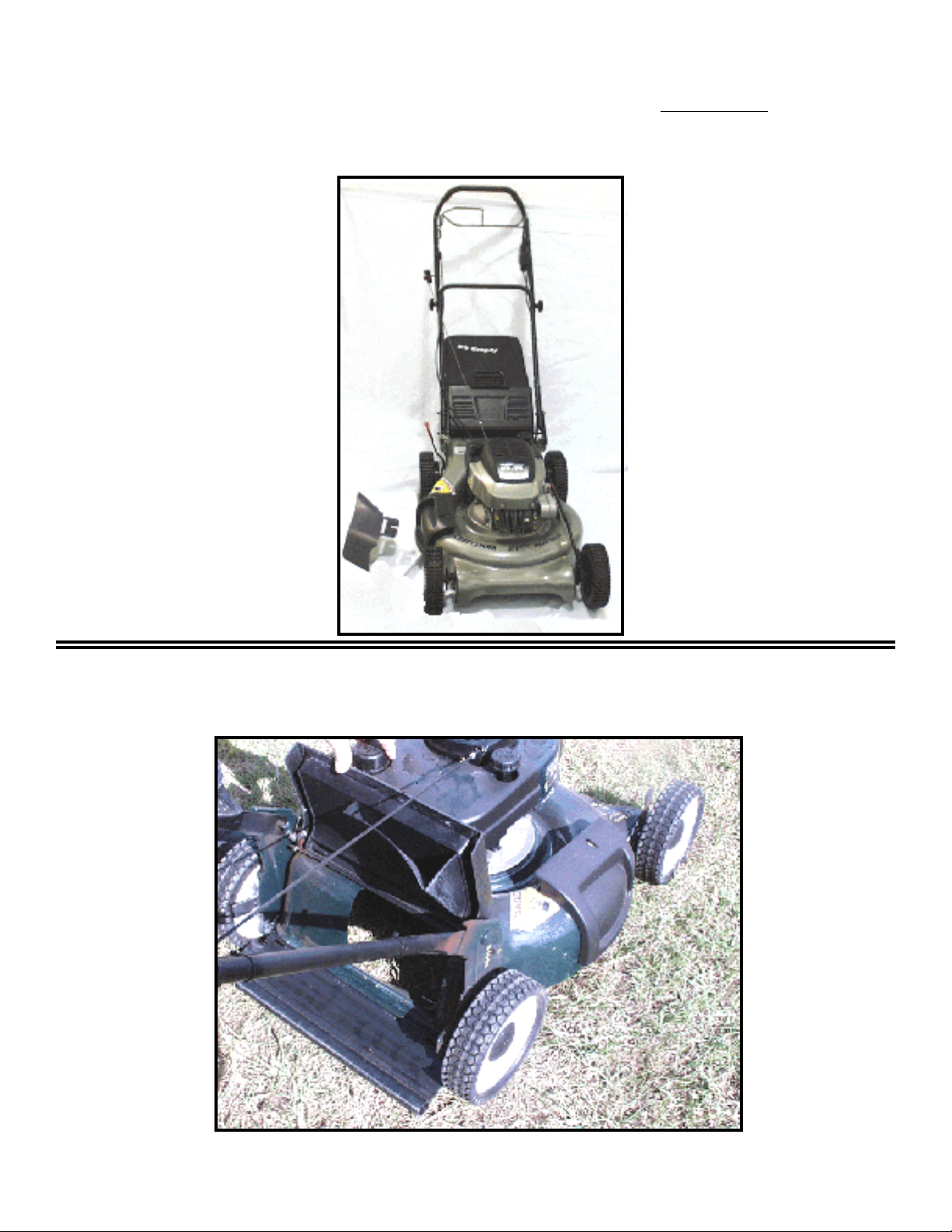
NEW for 1998 – on Rotary Mowers
NEW 21” Rear Drive Rear Bag / Mulcher with 10 Speeds
Also with redesigned Drive Bail / Also with models with Side Discharge Door
Ground speeds range from 1.9 to 2.7 m.p.h.
NEW 21” Dome Deck - Push Rear Bag / Mulcher
some models with Side Discharge Door
* Use 165833 Blade only with Push 21” Domed Deck
15
www.mymowerparts.com
Page 17
For Husqvarna Parts Call 606-678-9623 or 606-561-4983
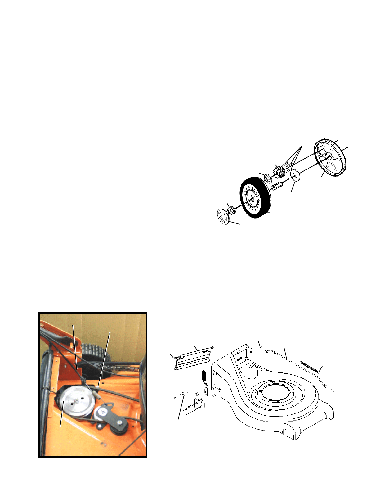
21” Rear Gear Drive Mower
Gearbox, Adjuster Assembly Tie Rod, or Adjustment Lever
Procedure for Teardown from Mower
1. Remove Fuel from engine.
2. Remove the rear Belt Cover.
3. Remove gearbox Pulley. Use screwdriver through pulley hole to keep pulley
from turning while the flange Nut is removed.
4. Remove Drive Cable from the Idler Bracket. Remove Screw holding transmission
bracket to the housing.
PAWL
5. Remove from each side:
Ý rear Wheel Covers,
PINION
E-RING
Ý rear Wheels.
Ý Clip Ring,
Ý Pinion,
Ý Pawls,
Ý large flat Washer,
FLANGE NUT
FLAT WASHER
WHEEL
DUST COVER
Ý Dust Cover.
HUBCAP
FIG. 1
6. Remove one Hinge Screw from right side to remove Rear Skirt.
7. Remove Spring from Connecting Rod. Remove the Connecting Rod.
8. Remove the Drive Assembly Retainer on both sides. The Gearbox, Rear Shaft Assembly, and
Selector Lever come out the bottom as an assembly.
DRIVE CABLE
SCREW
HINGE
SCREW
REAR SKIRT
RETAINING
SPRING
CONNECTING ROD
PULLEY
SPRING
DRIVE ASSEMBLY
RETAINER
FIG. 3
FIG. 2
16
www.mymowerparts.com
Page 18
For Husqvarna Parts Call 606-678-9623 or 606-561-4983
21” Rear Gear Drive Mower
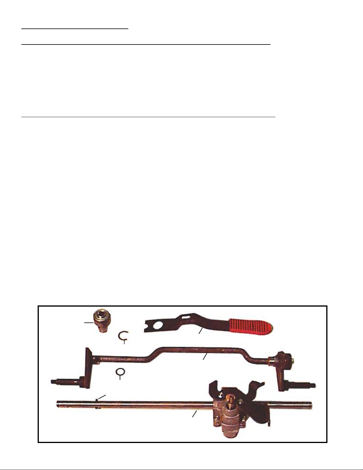
To Disassemble Gearbox, Adjuster Assembly, and Adjustment Lever
Ý Remove Roll Pin
Ý Remove Snap Ring holding bearing carrier to wheel adjustment assembly on the lever side.
Ý Slide off one Bearing Carrier.
Ý Slide Gearbox from rear Wheel Adjustment Assembly.
Ý Remove Height Adjustment Lever from gearbox shaft.
To Pre-Assemble Gearbox, Adjuster Assembly, and Adjustment Lever
1. If gearbox is replaced, install Gearbox Bracket from previous gearbox.
2. Position the rear Wheel Adjuster Assembly on the bench so that the cross rod is awayfrom you
and the ‘offset’ is on your right side.
3. Place adjustment Lever into the inside of the Wheel Adjustment Assembly bracket on your left
side. Locate the end of the adjustment Lever into cross rod.
The opening in the middle of the lever should be positioned to catch a tab
toward the center of the mower. Hold the Lever into the wheel adjuster
axle arm assembly while you start step 4.
4. Slide the washer onto long axle of the gearbox. Slide the long axle of the gearbox
into the wheel adjustment assembly bracket to your left. Slide the short shaft
into the wheel adjustment assembly bracket on your right. Slide a Bearing Carrier onto the
gearbox axle to your left. Work it through the bracket and adjustment Lever and secure with
a snap ring.
5. If the Bearing Carrier on the right side was disassembled, assemble into place now on the axle
and bracket on your right side. Secure this with a snap ring.
6. Put Washer next to bearing carrier and install Roll Pin in axle hole.
BEARING
RETAINER
SPRING SELECTOR
E-RING
REAR SHAFT ASSEMBLY
WASHER
ROLL PIN
GEAR BOX
FIG. 4
17
www.mymowerparts.com
Page 19
For Husqvarna Parts Call 606-678-9623 or 606-561-4983
21” Rear Gear Drive Mower
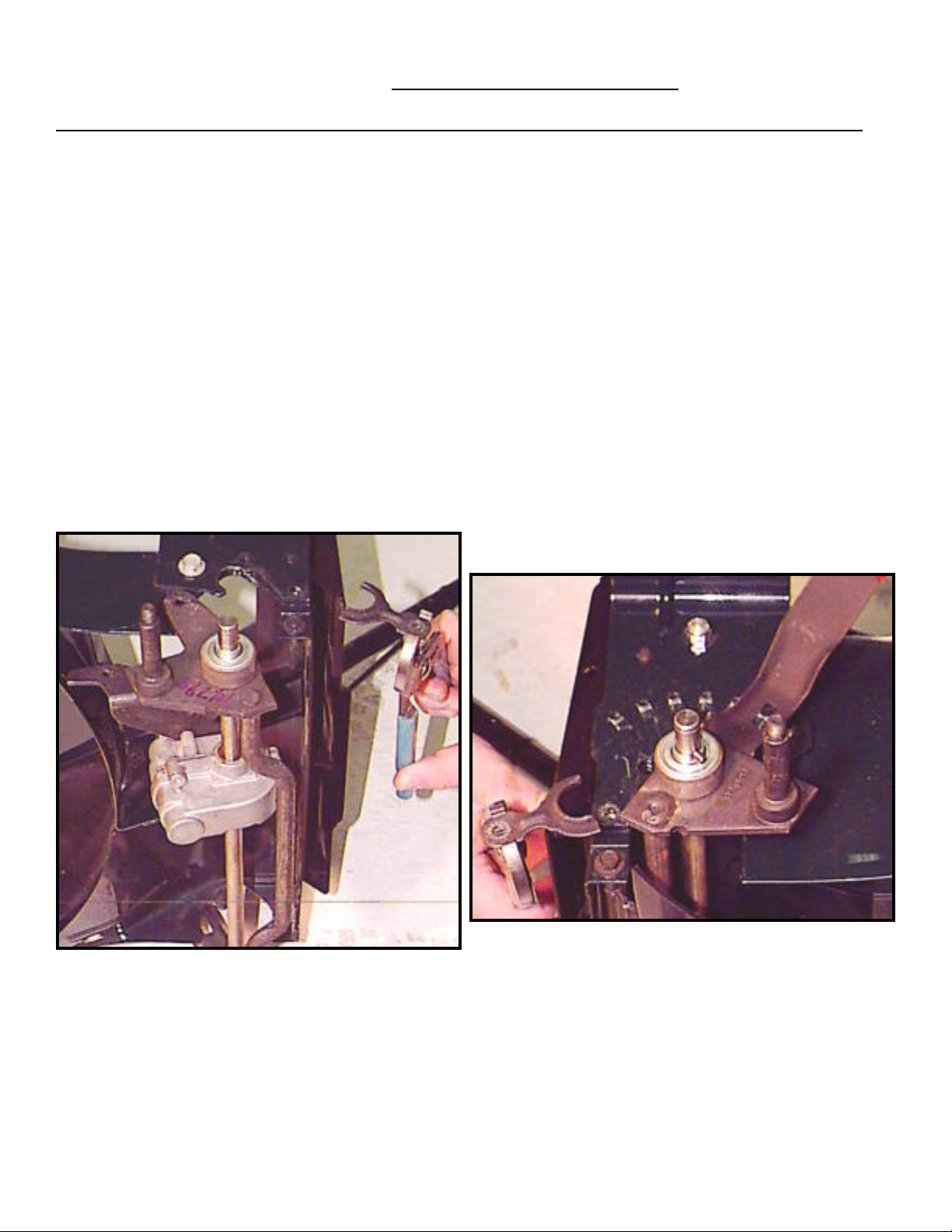
To Assemble Gearbox, Wheel Adjuster Assembly, and Spring Selector Lever
1. Place mower so that left side is up.
2. Place Gearbox/Rear Shaft Assembly into housing with Spring Selector Lever forward at the right
side (down). Put the left side bearing carrier into place first (at top) and secure with Drive
Assembly Retainer and the self tapping Screw. It may be necessary to shift the Bearing Support
upward into a ‘step’ that will set into the housing.
3. Install the connecting rod Spring from mower housing to the Hole in the Connecting Rod.
Install the Connecting Rod to front and rear shaft assemblies.
4. Install Dust Cover, Pinion *, Pawls, Snap Ring, large Flat Washer,
rear Wheel, Flange Nut and Wheel Cover.
5. Install Rear Skirt and change so the right side of mower is up.
FIG. 6
FIG. 5
6. Move Spring Selector Lever to second position from front position. Push bearing carrier into
place. There is a step in the bearing support that fits into the housing. Use axle pin to hold
assembly toward engine while installing Drive Assembly Retainer and screw.
18
www.mymowerparts.com
Page 20
For Husqvarna Parts Call 606-678-9623 or 606-561-4983
7. On the right side install the Dust Cover, Pinion *, Pawls, Snap Ring, E-Ring, large Flat Washer, rear
Wheel, Flange Nut, and Wheel Cover.
8. Place the mower flat on the ground.
9. Tighten all Nuts and Screws.
10. Install Screw holding gearbox bracket to housing. nstall Drive Cable.
11. Install Belt and Pulley onto the gearbox. Use screwdriver through hole in pulley
to keep pulley from moving while the Flange Nut is tightened to 15-20 Ft. Lbs.
12. Install the Belt Cover. Also install the mulcher plug or bagger.
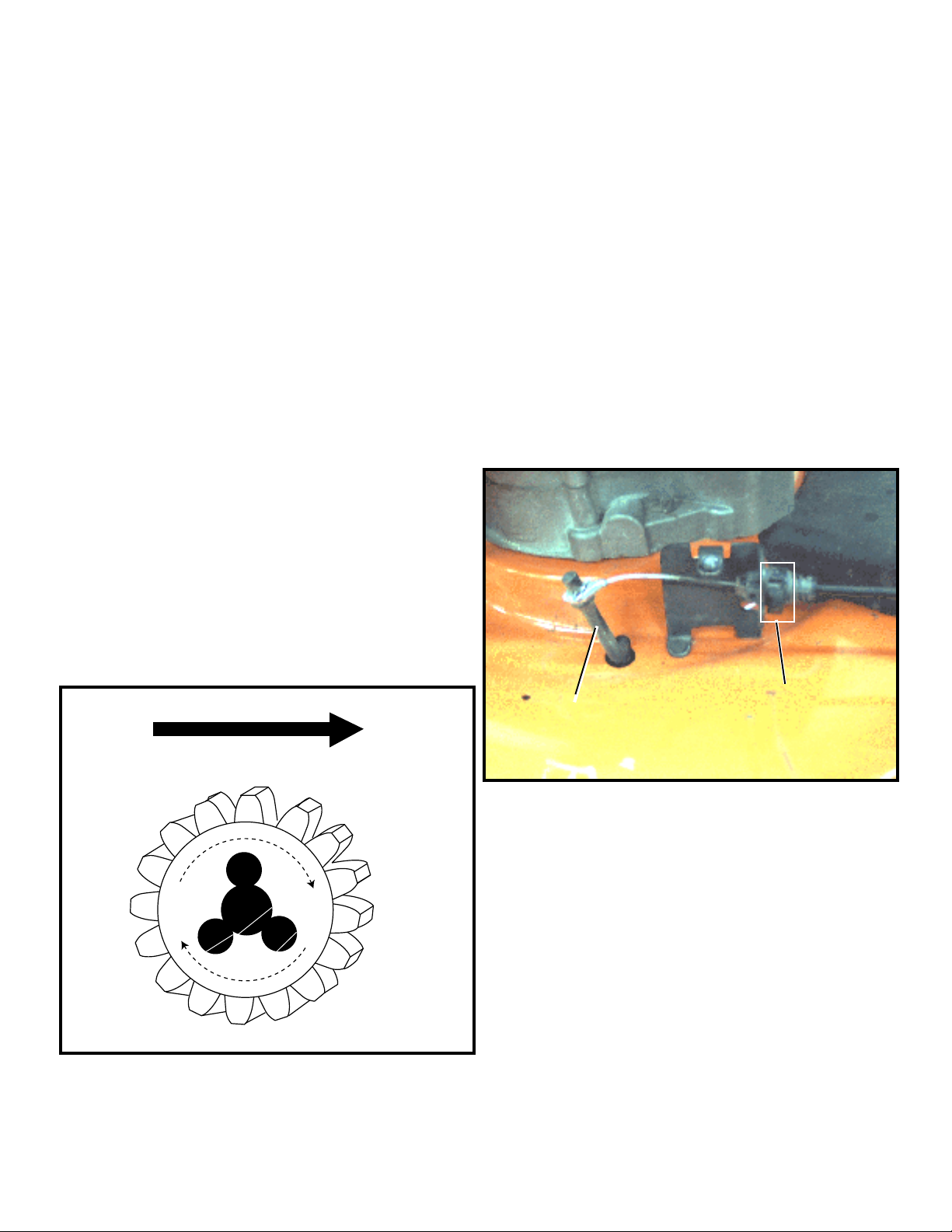
* The pinions on both sides are the same. It is critical
to assemble them in the correct position, see Fig 7.
There are arrows embossed on the pinion. The arrows
must point toward the front of the mower from the ‘up’
side. If the arrows point forward from the ‘down’ side,
remove the pinion and place the other side down.
Then install the three round Pawls and the E-Ring. DO
NOT USE oil or grease on the pinions or wheels. Use
WD40 or silicone lubricants only.
➡
Adjustment
Pivot Rod
FIG. 8
SPEED CABLE ADJUSTMENT
The speed cable must be adjusted during installation
to remove any slack. The slack would reduce the
range of speeds available. There is a Tab in the
cable where the conduit attaches to the mounting
bracket. Pull the tab out, push the Pivot Rod to the
farthest point forward, and push tab in to lock
adjustment in place .
Tab
FIG. 7
NOTE: Top arrow on pinion toward the front of the lawn mower .
www.mymowerparts.com
19
Page 21
For Husqvarna Parts Call 606-678-9623 or 606-561-4983
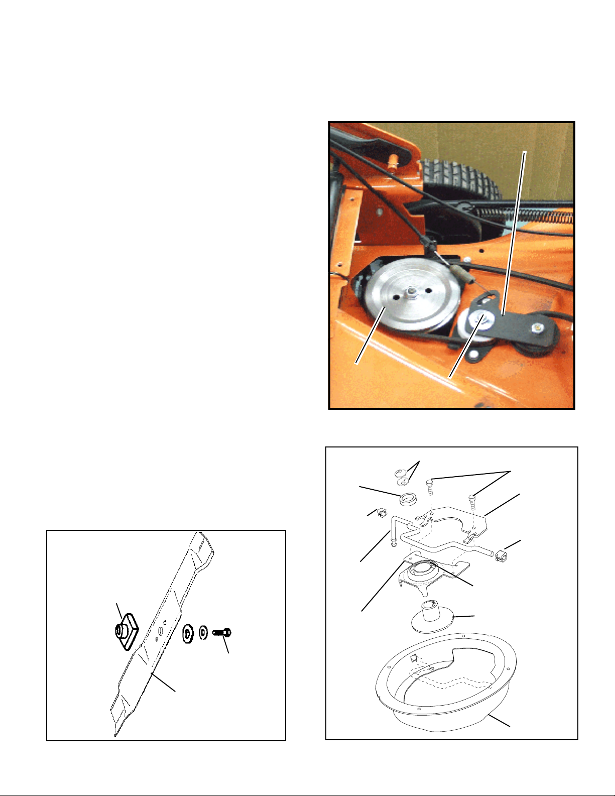
New - 21” Rear Drive Mower with 10 Speed Belt Replacement
Procedure
1. Remove the rear Belt Cover.
2. Remove the gearbox Pulley. Use a socket to
remove the pivot flange nut and the Idler
Bracket Assembly and place to the side.
3. Place mower on side with carburetor and
muffler up.
4. Remove the Blade, Blade Adapter Hardware,
and Blade Adapter. Remove the belt Cover.
Remove the belleville washers and spacer.
5. Remove the two screws holding the pivot rod
Clamp.
6. Remove the Bearing Support Assembly
(includes lower side of pulley).
7. Remove the belt.
8. Place new belt in pulley and pull through deck
toward gearbox.
9. Install the Bearing Support onto the crankshaft
with the pulley side toward the belt.
10. Install the pivot rod Clamp. Locate the clamp
into the pivot rod before installing screws.
11. Install the belt Cover.
12. Install the spacer, belleville washers, Blade
Adapter, Blade, hardened washer, lock washer,
and Grade 8 Blade Bolt. Torque the blade bolt
35 to 40 Ft. Lb.
Note: Two belleville washers should be
assembled with offset in opposite directions.
13. Place the mower upright. Install the belt and
pulley on transmission.
(Torque flange nut to 5 -10 Ft.Lb.)
14. Install engagement cable into idler bracket.
Install the idler bracket assembly onto belt and
deck. (Torque flange nut to 8 - 11 Ft.Lb.)
15. Replace the belt cover.
Pulley
Pivot Nut
FIG. 10
Belleville Washers
Spacer
Pivot Rod
Bushing
Idler
Bracket
Hex Bolt
Clamp
Pivot Rod
Bushing
BLADE
ADAPTER
FIG. 9
Pivot Rod
Bearing
Support
BLADE BOLT
BLADE
20
www.mymowerparts.com
Lower
Pulley
Upper
Pulley
Cover
Assembly
FIG. 11
Page 22
For Husqvarna Parts Call 606-678-9623 or 606-561-4983
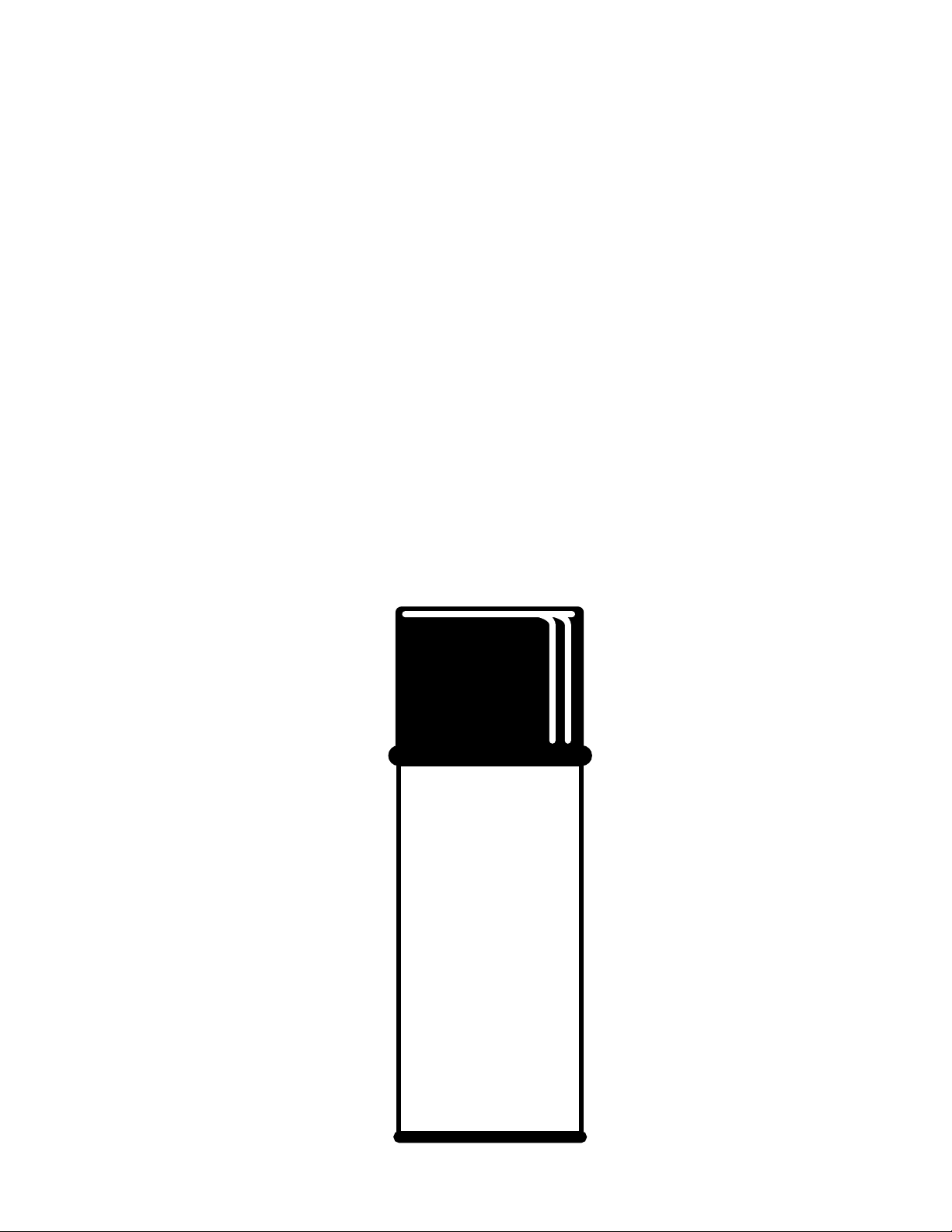
Touch - Up Paints for Lawn & Garden
PART NUMBER DESCRIPTION PAINT CODE
71 / 917 / 150020 POLO GREEN Spray Paint 558
71 / 917 / 150131 SATIN BLACK Spray Paint
71 / 917 / 130937 DOVER GRAY Spray Paint 459, 478
71 / 917 / 126967X NEW SEARS SILVER Spray Paint 417
71 / 917 / 136247 RED Spray Paint 505, 506, 394, 423
71 / 917 / 126965X ORANGE Spray Paint 412, 422
71 / 917 / 126966X GRAY Spray Paint 410, 418
71 / 917 / 144401 GREEN Spray Paint 550
71 / 917 / 126963X GREEN (New RALLY) Spray Paint 419
71 / 917 / 130939 GREEN ( POULAN ) Spray Paint 419
71 / 917 / 126964X YELLOW ( POULAN PRO ) Spray Paint 416, 421
71 / 917 / 130941 YELLOW Spray Paint 472, 473
71 / 917 / 136246 BLUE (Dark) Spray Paint 510, 511
71 / 917 / 108521X BRONZE ( Old Roper ) Spray Paint 388
71 / 917 / 126687X BRONZE ( New Roper ) Spray Paint 425
CUSTOM
SPRAY
POLO GREEN
NET WT. 12 0Z. (340g)
21
www.mymowerparts.com
Page 23
For Husqvarna Parts Call 606-678-9623 or 606-561-4983
TIRE SEALANTS for Lawn & Garden
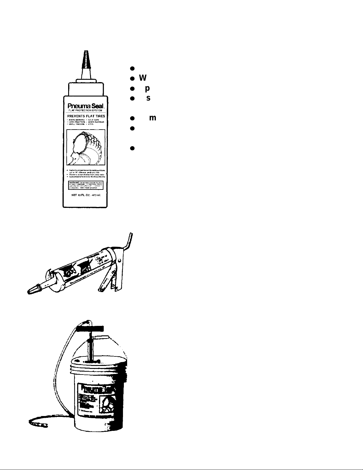
Pneumaseal tire sealant:
l
Seals tread punctures to 1/4”
l
Will not freeze to - 37 degrees C
l
Applications up to 35 mph
l
Installed quickly and easily through
tire valve stem
l
Eliminates slow leaks in the tread area
l
Will not affect paint on tire rim
or cause rust
l
16 oz. container comes with tool
to remove and install valve in stem
and tool to get sealant into tire
71 / 071 / 24225 Pneumaseal 16 oz. Bottle
Also Available:
92 / 192 / 144334 Pneumaseal 10 oz. Caulking Tube
92 / 192 / 144335 Pneumaseal 5 gallon pail
92 / 192 / 100035 Pump for Pneumaseal pail
22
www.mymowerparts.com
Page 24
For Husqvarna Parts Call 606-678-9623 or 606-561-4983
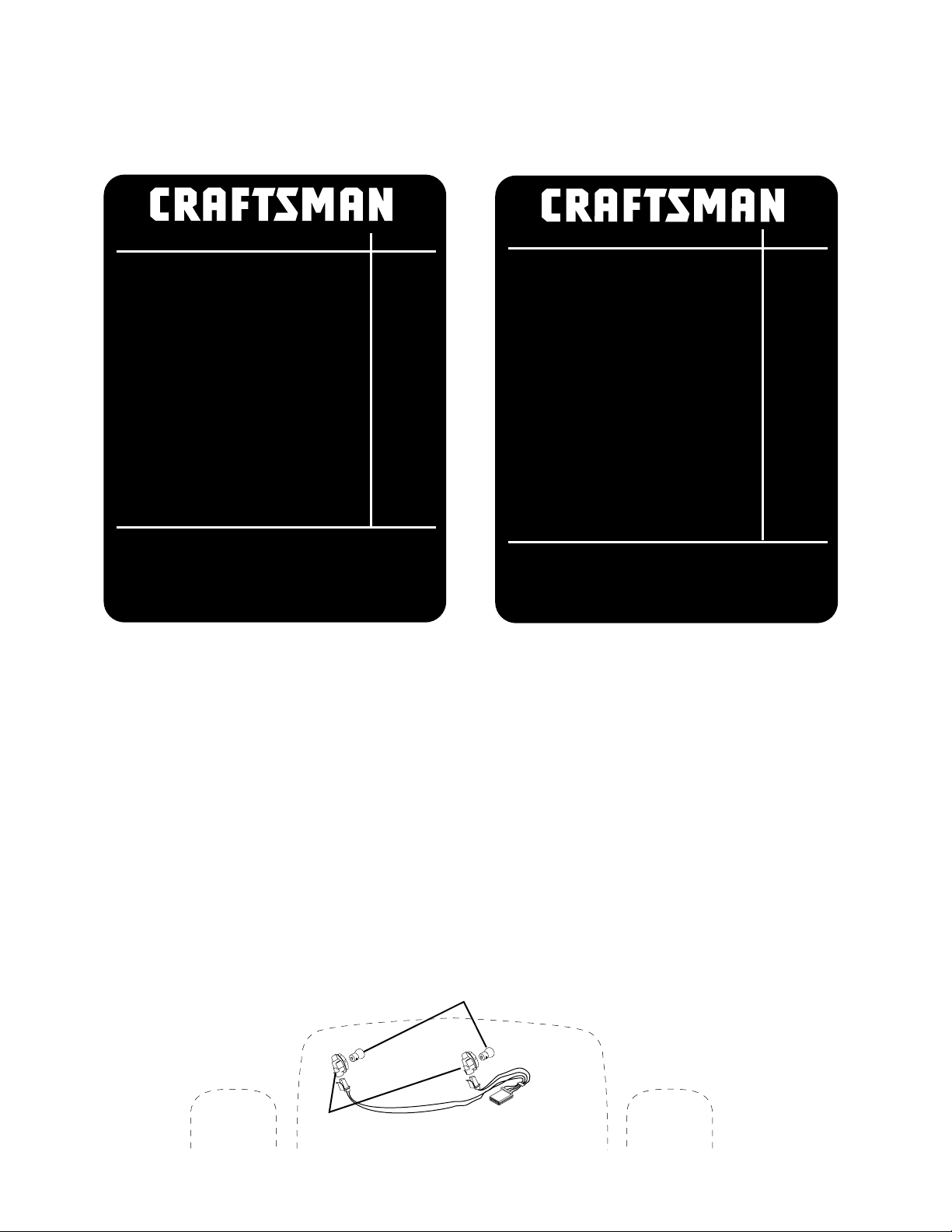
NEW for 1999 T ractors
9J
Description Part # Stock #
42" Blade (2) 24676134149
Ground Drive Belt 24102130801
Primary Mower Belt 24104144200
Air Filter 12-083-16
Pre-cleaner 12-083-11
Spark Plug 85871RC12YC
Oil Filter 52-050-02
Fuel Filter
Keys
Battery
Oil Capacity (oz) 64 oz
Parts available at most Sears Retail
Stores and Service Centers or call
1-800-366-PART if you want the part
sent directly to your home.
25-050-03
109310X
30 amp
24697
9R
Description Part # Stock #
46" Blade (3) 163819
Ground Drive Belt 140218
Primary Mower Belt 148763
Secondary Mwr Belt 24690144959
Air Filter 24-083-03
Pre-cleaner 24-083-05
Spark Plug 85871RC12YC
Oil Filter 52-050-02
Fuel Filter
Keys
Battery
Oil Capacity (oz) 64 oz
Parts available at most Sears Retail
Stores and Service Centers or call
1-800-366-PART if you want the part
sent directly to your home.
24-050-02
140403
35 amp
24606
24040
Some product lines of tractors in 1999 will have a decal under the hood to show the part
numbers of the most commonly used parts on that model.
TECHNICAL TRAINING AND SERVICE INFORMATION BOOKS
P ART NUMBER DESCRIPTION from F.H.P. 917 order from D92/192
163578 On-Site Service Manual (Tractors & Rear Tine Tillers)
163579 Shop Service Manual (Lawn Mowers & Front Tine Tillers)
163580 1998 Craftman & Wizzard Tractor , Mower , Tiller Accessories
163581 1998 Craftman & Wizzard Tractor Wiring Accessories
168830 1999 Service Update Book
SEARS STEALTH HOOD TRACTOR MANUALS IN 1998
OMITTED THE HEADLIGHT SOCKET 71/917/163996
4152J
163996
23
www.mymowerparts.com
Page 25

For Husqvarna Parts Call 606-678-9623 or 606-561-4983
NOTES
24
www.mymowerparts.com
Page 26

For Husqvarna Parts Call 606-678-9623 or 606-561-4983
Printed in U.S.A. 168830 12/22/98 VFH
www.mymowerparts.com
 Loading...