

Page 1

For Husqvarna Parts Call 606-678-9623 or 606-561-4983
www.mymowerparts.com
Page 2

For Husqvarna Parts Call 606-678-9623 or 606-561-4983
NOTES
2
www.mymowerparts.com
Page 3

For Husqvarna Parts Call 606-678-9623 or 606-561-4983
Table of Contents 3
Seat Pan changed for easier assembly 4
Oil Drain 4
Solenoid / Fuse / PTO Switch 5
Solenoid Diagnostic Procedure 6
Electrical Components Quick List 7
Hydro Gear 0510 Service Information 8
Hydro Gear 0510 Neutral Adjustment for Lever LT 9
Lever Controlled Automatic LT Neutral Adjustment 10
Foot Controlled Automatic LT Speed Adjustment 11
Quick Attach Bagger 11
Cruise Control for Foot Pedal Operated LT Automatic 12
New GT Automatic Belt Replacement Procedure 13
New GT Automatic Starting Procedure for Extreme Cold 13
Hydro Gear 3000 for Garden Tractors Service Information 14
Hydro Gear 3500 Return to Neutral Adjustment for Trans 15
GT Automatic Speed Lever Neutral Adjustment for Tractor 16
GT Muffler changes 16
Blade Listing 17
New Front Suspension for Mowers 18
New Mandrel for 48” Mower 18
New 48” H.D. Mower 19
KOHLER Liquid Cooled V-Twin 20-21
New 21” Front Drive Mower 22-24
Touch-Up Paints 25
New Weed Trimmer 26-27
21" Rear Drive Adjustments 28-29
42" Mower Cable Clutch Kit # 175067 30
3
www.mymowerparts.com
Page 4

For Husqvarna Parts Call 606-678-9623 or 606-561-4983
Quick Attach Tractor Seat
Tractors will now be shipped with a quick attach seat that will have a quick install feature for the seat shoulder bolt. The seat will have the shoulder bolt mounted from the
factory. The customer will place the shoulder bolt over the front end of the slot and
push down. The head of the shoulder bolt will go through and is retained. The seat
knob and washer is then installed.
Quick Release Tractor Engine Oil Drain Valve
148456 Oil Drain Tube
162295 Elbow
148315 Oil Drain
A quick release oil drain valve will be on many 2001 tractor engines. The drain is
released with a slight push and a counterclockwise turn. There is a yellow cap on end
that will retain oil if the valve is not properly closed. Customers will be supplied a 10”
clear PVC tube to help drain the oil into a container. The tube is a 3/8” I.D. clear PVC
and can be purchased in bulk locally.
The valve has special threads that do not require pipe dope or teflon tape that is
needed for the brass elbow used on some twin cylinder engines.
4
www.mymowerparts.com
Page 5

For Husqvarna Parts Call 606-678-9623 or 606-561-4983
New Solenoid # 171141
• Yellow Di-Chromate finish for improved corro-
sion resistance inside and out over previously
used zinc finish.
• Lowered Voltage contact surface pull in, as
low as 8.5 VDC.
• Coil Resistance is 3.8 to 4.3 Ohms. Previous
solenoids were 5.0 to 6.5 Ohms.
• The Solenoid Kit number will continue to be
146154.
FUSE change on Lawn Tractors
A 20 AMP fuse part number 175158 will now
be used on lawn tractors. Lawn tractors made
in 1999 and 2000 with a 15 AMP fuse can also
use the 20 AMP fuse.
GTs will still use the 30 AMP fuse.
Yellow
Di-Chromate
15
20
30
A 30 AMP FUSE SHOULD NEVER BE USED IN
PLACE OF A 15 OR 20 AMP FUSE.
PTO SWITCH CHANGE
The new PTO Switch will have 8 terminals instead of 7 terminals.
The switch with 8 terminals can be used for
product made before 2001.
Part numbers for the new and old switches are
on the page 5 electrical parts reference.
There will be a new 175567 snap-in Ignition
Switch for tractors without headlights.
CG
F
H
B
E
A
D
PTO SWITCH
OFF
CIRCUITPOSITION
C + G, B + H
C + F, B + E, A + DON
5
www.mymowerparts.com
Page 6

For Husqvarna Parts Call 606-678-9623 or 606-561-4983
Diagnosis of Starter Solenoids
• Remove the red cable from the engine starter motor before testing.
• Place digital meter selector on D.C. Voltage scale that includes 13 Volts.
Step # 1.
12.6
1. Place meter probes on battery terminals. If the
reading is 12.2 VDC or more, proceed to the next
step. If the reading is below 12.2 VDC, charge or
replace the battery with one that has at least
12.2 V DC.
Step # 2.
(-)
(+)
A
1. Connect negative (black) meter lead to the battery
negative (-) terminal.
2. Connect the positive (red) meter lead to the ‘hot’
terminal of the solenoid.
3. Note the voltage reading.
Step # 3.
1. Keep the meter selector in the same position and
the negative meter lead connected to the battery
negative terminal.
2. Connect the positive (red) meter lead to the end of
the cable normally connected to the starter motor.
3. Engage the parking brake and turn the ignition
switch to the “START” position.
4. Note the voltage reading.
5. If the voltage drop is more than 0.50 VDC between
the two noted readings, the solenoid or the starter
cable is suspect. Replace the solenoid.
6. Re-install the red cable to the starter motor.
If the solenoid checks acceptable and the starter
does not crank, check for clean tight battery
connections and check the grounds for the
battery and the engine.
A
12.4
(-)
B
B
(+)
6
www.mymowerparts.com
Page 7

For Husqvarna Parts Call 606-678-9623 or 606-561-4983
7
www.mymowerparts.com
Page 8

For Husqvarna Parts Call 606-678-9623 or 606-561-4983
The 0510 Automatic Transmission
from HYDRO-GEAR for Lawn Tractors
Oil should NOT be checked unless there is a complaint about the operation of the transmission.
There is a gold colored plug in the top of the transmission. Clean the underside of the frame and the
top of the transmission before checking the oil level. Contamination cannot be allowed to get into the
transmission. When the plug is removed, a 6 inch metal scale can be used to check the oil level.
When the transmission is cold, the oil level should be from .50 to 1.25 inches from the top of the
casting. 20W50 engine oil can be added to the level of the bottom thread for the oil plug. The oil
never needs to be changed for maintenance.
The 0510 transmission has an expansion tank. This allows for oil to expand into the tank
when the transmission is hot, and as the oil cools it is drawn back inside the transmission.
The expansion tank will be silver-gray in color and should not be opened.
If you are working on a tractor where the operator experiences transmission complaints:
• Check to see that the brake return spring is in position.
• Check the movement of the by pass valve and the freewheel control rod.
• Check the brake adjustments, if adjusted too tight, the transmission can overheat.
1-9/16"
Brake Rod Spring Adjustment Brake Disc / Puck Clearance
8
www.mymowerparts.com
Page 9

For Husqvarna Parts Call 606-678-9623 or 606-561-4983
NEUTRAL ADJUSTMENT FOR LAWN TRACTORS
WITH LEVER CONTROL
1. Place the tractor on a smooth paved level surface.
2. Loosen Adjustment Bolt in front of the right rear wheel, and lightly tighten using a 1/2"
wrench.
3. Start Engine and move Lever until tractor does not move forward or backward.
Hold Control Lever in that position and do not move. Turn the engine off.
4. While holding the Control Lever to keep it from moving, loosen theAdjustment Bolt . Move the
Control Lever to the position indicated for Neutral on the fender. Tighten Adjustment
Bolt securely.
FINE TUNE THE NEUTRAL ADJUSTMENT ON AUTOMATIC DRIVE
1. Place the tractor on a smooth paved level surface.
2. Loosen the Adjustment Bolt using a 1/2" wrench. If the tractor is creeping forward, move the
Control Lever forward 1/4 to 1/2 inch. Move the Control Lever rearward 1/4 to 1/2 inch if the
tractor is creeping backwards. Tighten the Adjustment Bolt securely.
3. Start engine and test from both forward and reverse.
4. If tractor still creeps, repeat step # 2 until satisfied.
NOTE: If additional clearance is needed to get to adjustment bolt, move mower deck height to
the lowest position.
9
www.mymowerparts.com
Page 10

For Husqvarna Parts Call 606-678-9623 or 606-561-4983
RETURN TO NEUTRAL ADJUSTMENT Lawn Tractor
Hydro Gear 0510 Automatic Transmission
with Footpedal Control
WARNING: Potential for Serious Injury
Certain procedures require the engine to be operated and the tractor is raised off the ground.
To prevent possible injury to the technician or bystander, insure the tractor is properly
secured.
The return to neutral mechanism on the transmission is designed to go to the neutral position after
the operator’s foot is removed from the foot pedals.
Use illustration at the bottom of page.
1. Confirm the freewheel rod at the back of the tractor is in the position for the transaxle to move the
tractor. Raise the rear tires of the tractor off the ground to allow free rotation.
2. Remove the tractor footpedal linkage from the transmission control arm. NOTE: It may be neces-
sary to remove the drawbar plate or the right rear wheel to remove the tractor footpedal
linkage.
3. Start the engine and raise the throttle to full speed.
4. Check for axle rotation. If the axles do not rotate, go to step 5. If the axles do rotate, go to
step 6.
5. Stop the engine. Reattach the footpedal linkage then recheck using steps 3 and 4. If the axles
do not turn, the adjustment is completed. Stop engine.
6. Note the direction of rear axle rotation of the right rear axle. Stop the engine. Loosen the adjusting puck screw until the puck can be rotated. Rotate the puck in the opposite direction of the
wheel rotation in 5 degree increments. Tighten the adjusting puck screw to 250 to 320 inch
pounds. Recheck using steps 3 and 4. Stop the engine. Continue to adjust the puck and test
until the rear axles do not rotate. Reattach the footpedal linkage then recheck using steps 3 and
4. If the axles do not turn, the adjustment is completed. Stop engine.
WARNING: Do not attempt to make
any adjustments with the engine running.
Use extreme caution while inspecting the
vehicle linkage.
www.mymowerparts.com
10
Page 11
For Husqvarna Parts Call 606-678-9623 or 606-561-4983
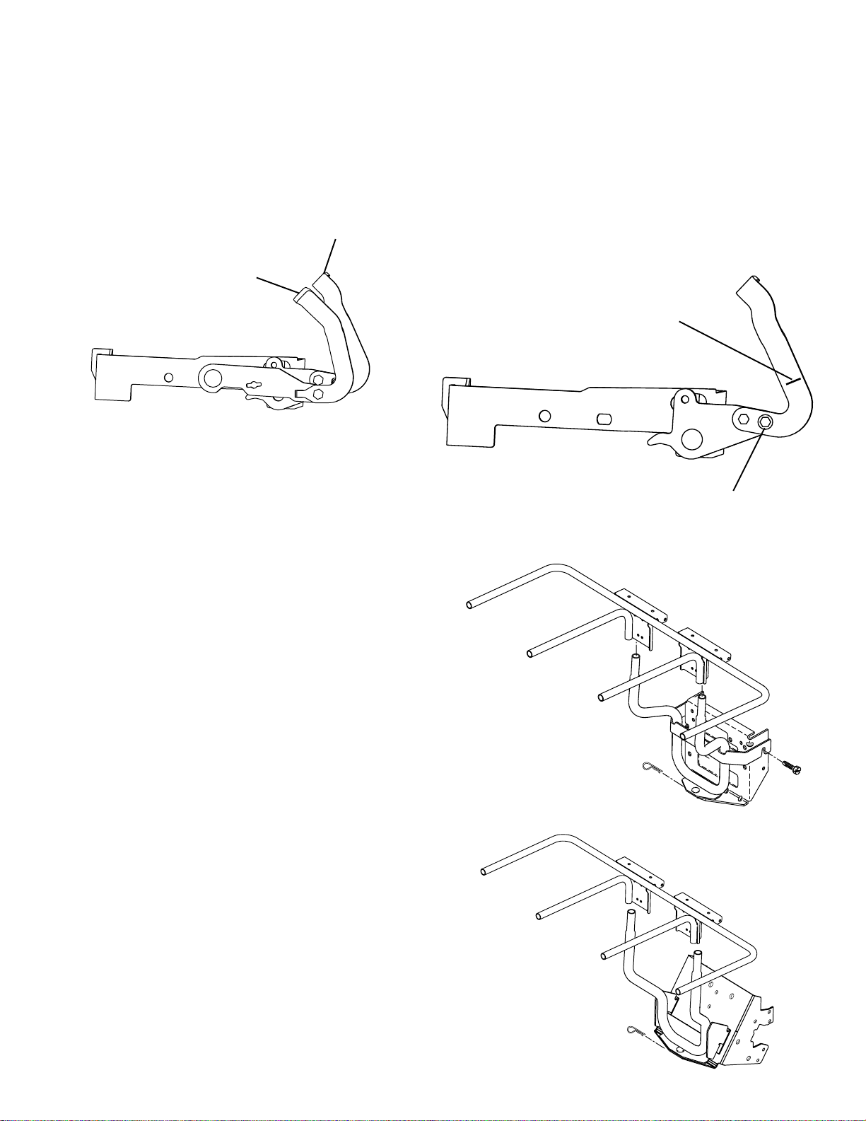
Forward Speed Adjustment for Footpedal Control
Lawn Tractors
Loosen indicated bolt under the footpad. Find the alignment mark in the metal at the base of the
forward foot pedal. Hold the pedal to align the mark with the edge of the footpad, and tighten the
bolt.
FORWARD
PEDAL
REVERSE
PEDAL
ALIGNMENT MARK
ADJUSTMENT BOLT
Three Bin Baggers with Quick Attach Improvements
Bagger Attachments with three bins
will have improvements to make
assembly easier.
The Bracket for lawn tractors will
have two shoulder bolts at the top
of each side of the drawbar plate.
The Bracket will fit over the shoulder
bolts and is secured with a Retainer Spring.
The Bracket for garden tractors will
fit into two slots in the angled
drawbar plate. A Retainer Spring
will secure the bracket.
LT Bagger Mounting Bracket
Brackets and chutes will be the
major differences between
baggers for 46” and 48” mowers.
www.mymowerparts.com
GT Bagger Bracket
11
Page 12
For Husqvarna Parts Call 606-678-9623 or 606-561-4983
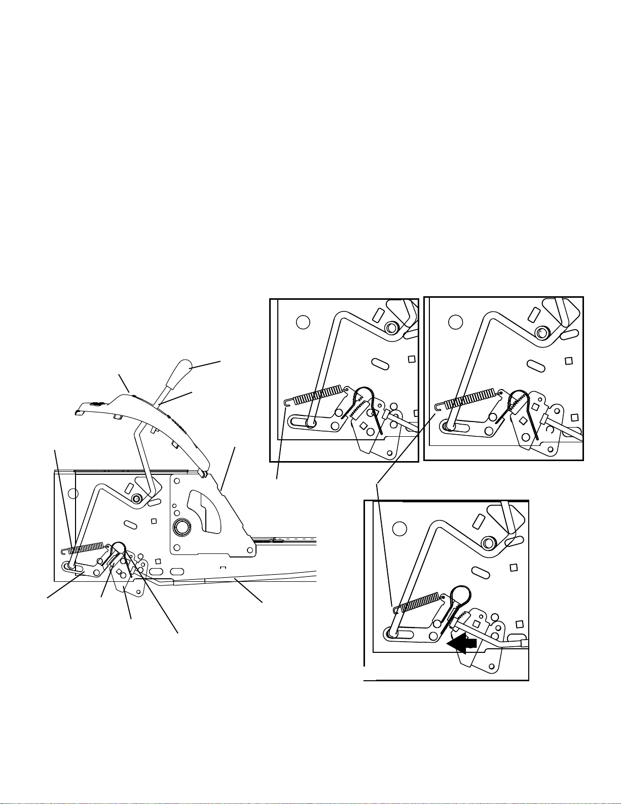
CRUISE CONTROL FOR FOOT PEDAL OPERATED
AUTOMATIC LT
There will be an actuating rod for the cruise control with a knob on the right fender. The operator
uses the forward foot pedal to get the desired forward speed; then pushes forward on the knob to
engage the cruise control. This causes the teeth of the Cruise Pawl to engage the Cruise Sector
Gear, which will hold the transmission Control Arm in the position for that speed.
The operator can disengage the Cruise Control manually by pulling backwards on the fender Cruise
Knob or by using the forward speed pedal to go faster. This pulls the teeth of the cruise pawl out of
the sector gear and the tractor will slow to neutral unless the operator pushes on the pedal.
The brake rod can also disengage the Cruise Control. There is a locknut on the end of the brake rod
that will push on the Cruise Disengage Actuator Spring. This will push the Cruise Pawl away from the
Cruise Sector Gear and the automatic transmission will go to neutral and the transmission will not be
able to fight the operation of the brake.
Disengaded
Engaged
Cruise
Spring
Pawl
Cruise
Console
Sector
Arm
Actuator Spring
Knob
Lever
Chassis
Attached toTransaxle
Brake Rod
Brake Disengaging Cruise Pawl
* There is a Damper Cylinder in the system to smooth the tractor speed changes when the cruise
control is disengaged. If the operator complains that the tractor jerks or is not smooth, this part may
need to be replaced. You should correct for any loose fitting parts in the system and re-test before
replacing the damper cylinder.
12
www.mymowerparts.com
Page 13
For Husqvarna Parts Call 606-678-9623 or 606-561-4983
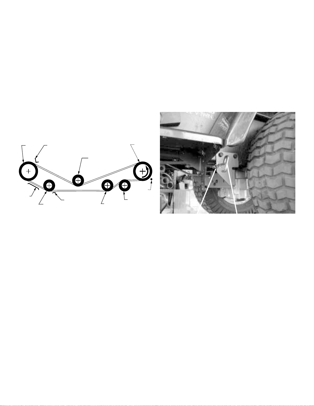
DRIVE BELT REPLACEMENT PROCEDURE
Garden Tractor with Hydro Gear 3000/3500 series
Automatic Transmission
• Remove the mower deck from the tractor.
• Remove the Retainer Spring from the Drive Belt Tension Handle located under the left footpad
near the rear tire.
• Remove the old belt from the idler pulleys, transaxle pulley, and then from the engine pulley.
• Start the new belt at the tractor front on the engine pulley, install on the transaxle pulley, and
last into the idlers. Check belt keeper positions.
• Replace the Retainer Spring in the engaged Drive Belt Tension Handle.
• Re-install the mower.
ENGINE
PULLEY
BELT
KEEPER
BELT
KEEPER
V-IDLER
BELT
KEEPER
FLAT IDLER
CLUTCHING
V-IDLER
TRANSAXLE
PULLEY
BELT
KEEPER
CLUTCHING
FLAT IDLER
Retainer Spring
Tension Handle
Drive Belt Routing Drive Belt Tension Handle
PROCEDURE TO START ENGINE IN EXTREME COLD
Garden Tractor with Hydro Gear 3000/3500 series Automatic
If the engine will not start and the outside temperature is extremely cold, the operator may need to
perform this procedure.
• Depress the foot pedal and engage the parking brake rod. The parking brake must remain
engaged until this procedure is completed.
• Locate the handle under the left side footpad near the rear tire.
• Remove the Retainer Spring from the Drive Belt Tension Handle to relieve tension on the drive
belt.
• Start the engine and allow it to warm for 3 minutes.
• Engage the Drive Belt Tension Handle and replace the Retainer Spring.
CAUTION: If the Drive Belt Tension Handle is left in the disengaged position, the tractor will not
move without tension on the drive belt.
13
www.mymowerparts.com
Page 14
For Husqvarna Parts Call 606-678-9623 or 606-561-4983
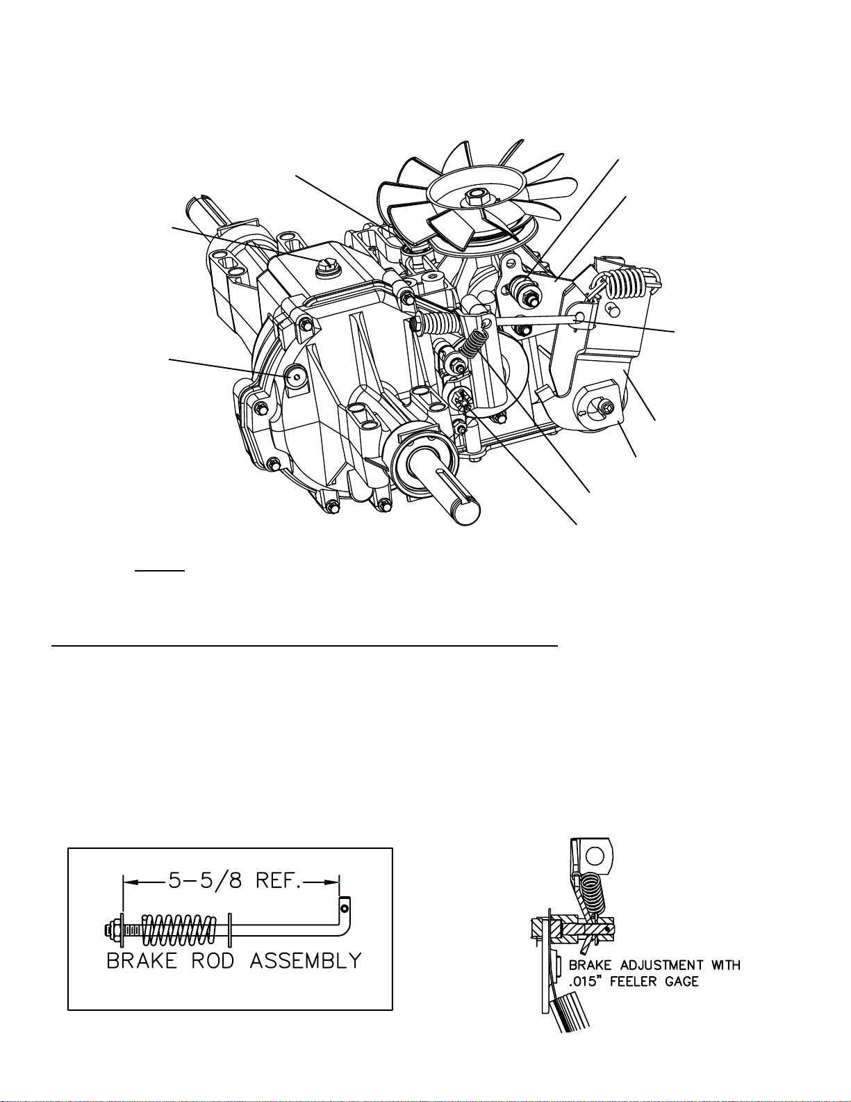
The 3000 / 3500 AUTOMATIC TRANSMISSION from
HYDRO-GEAR for GARDEN TRACTORS
Speed Control Level
By-Pass Level
Opening for Oil fill
& Breather Tube
Oil Level Plug
Adjustment
Control Arm
Brake Pull Rod
Return Actuating
Arm
Adjusting Puck
Brake Return Spring
Brake Adjusting Nut
Oil should NOT be checked unless there is a complaint about the operation of the transmission. There is a gold colored plug in the right rear of the transmission case . Clean
the underside of the frame and the top of the transmission before checking the oil level.
Contamination cannot be allowed to get into the transmission. Place the tractor on a
level surface and remove the drawbar plate. When the plug is removed, the oil should
come to the bottom of the opening. 20W50 engine oil can be added to the level of the
bottom of the oil plug. The oil never needs to be changed for maintenance.
If you are working on a tractor where the operator experiences transmission complaints:
• Check to see that the neutral return adjustments for the transmission and the tractor
are correct. ( Both are elsewhere on this manual.)
• Check the movement of the by pass valve and the freewheel control rod.
(This is not an adjustment)
www.mymowerparts.com
14
Page 15

For Husqvarna Parts Call 606-678-9623 or 606-561-4983
RETURN TO NEUTRAL ADJUSTMENT GT
Hydro Gear 3000/3500 Automatic Transmission
with Hand Control
WARNING: Potential for Serious Injury
Certain procedures require the engine to be operated and the tractor is raised off the
ground. To prevent possible injury to the technician or bystander, insure the tractor is
properly secured.
The return to neutral mechanism on the transmission is designed to go to the neutral position after
the operator’s foot fully depresses the foot pedal .
1. Confirm the freewheel rod at the back of the tractor is in the position for the transaxle to move the
tractor. Raise the rear tires of the tractor off the ground to allow free rotation.
2. Remove the tractor linkage from the hand control from the transmission control arm. NOTE: It
may be necessary to remove the drawbar plate or the right rear wheel to remove the
linkage.
3. Remove the cotter pin and the washer securing the brake pull rod to the return actuating arm.
Remove the rod from the return actuating arm.
4. Push the tractor foot pedal down and lock the parking brake rod. Start the engine and raise the
throttle to full speed.
5. Check for axle rotation. If the axles do not rotate, go to step 6. If the axles do rotate, go to step
7.
6. Stop the engine. Reattach the hand control linkage then recheck using steps 4 and 5. If the
axles do not turn, the adjustment is completed. Stop engine. Re-install the brake pull rod in the
return actuating arm using the washer and a new cotter pin.
7. Note the direction of rear axle rotation of the right rear axle. Stop the engine. Loosen the adjusting puck screw until the puck can be rotated. Rotate the puck in the opposite direction of the
wheel rotation in 5 degree increments. Tighten the adjusting puck screw to 250 to 320 inch
pounds. Recheck using steps 4 and 5. Stop the engine. Continue to adjust the puck and test
until the rear axles do not rotate.
8. Reattach the hand control linkage then recheck using steps 4 and 5. If the axles turn, perform the
Neutral Adjustment for the tractor Automatic Speed Lever on page 14. Stop engine.Re-install
the brake pull rod in the return actuating arm using the washer and a new cotter pin.
WARNING: Do not attempt to make any adjustments with the engine running. Use extreme
caution while inspecting the vehicle linkage.
www.mymowerparts.com
15
Page 16

For Husqvarna Parts Call 606-678-9623 or 606-561-4983
Neutral Adjustment for GT Automatic Speed Lever
Garden Tractor with Hydro Gear 3000 series Automatic
• Place the parking brake in the engaged
position.
• Loosen the position bolt on the automatic
lever assembly, under the right fender.
• Move the automatic speed lever into the
fender console neutral slot.
• Tighten the position bolt on the lever
assembly.
If this procedure does not solve the problem, it
will be necessary to do the neutral adjustment on
the Hydro Gear 3000 or 3500 transaxle, before
doing this procedure again.
FRONT MUFFLERS ON 2001 GARDEN TRACTORS
GARDEN TRACTORS BEFORE 2001 HAD
THE MUFFLER BESIDE THE ENGINE
2001 GARDEN TRACTORS HAVE THE MUFFLER IN
FRONT OF THE ENGINE
KOHLER Command Twin cylinder engines will
have an integral solenoid shift starter in 2001.
The solenoid will be on the engine, not on the
tractor
.
www.mymowerparts.com
16
Page 17

For Husqvarna Parts Call 606-678-9623 or 606-561-4983
* BLADE LISTING *
by RETAINER HOLE CHARACTERISTICS
PART DECK CONSTRUC- TYPE DECK HOLE(S) BLADE RETAIL
NUMBER SIZE TION TYPE BOLT(S) NUMBER
145106 20" REGULAR MULCH 3 1 71-33255
146749 20" PREMIUM MULCH 3 1 71-33271
701211 20" PREMIUM STANDARD 3 1 71-33270
850972 20" REGULAR STANDARD 3 1 71-33233
154208 20" ELECTRIC MULCH CAST DECK 3 1
156716 20" ELECTRIC MULCH REAR DISCHARGE 3
159267 21" REGULAR MULCH REAR DRIVE 3 1 71-33273
161541 21" REGULAR ST ANDARD REAR DRIVE 3 1
165833 21" REGULAR MULCH PUSH 3 1 71-33274
175064 21” REGULAR MULCH / BAG FRONT GEAR 3 1
176135 21” PREMIUM MULCH / BAG FRONT GEAR 3 1
175052 21” REGULAR MULCH ONLY FRONT GEAR 3 1
152202 22" REGULAR MULCH SIDE DISC EZ3 3
157101 22" REGULAR MULCH REAR DISCHARGE 3 3 71-33269
141114 22" REGULAR MULCH 3 1 71-33256
141443 22" PREMIUM MULCH 1 71-33272
701213 22" PREMIUM STANDARD 1 71-33223
850973 22" REGULAR STANDARD 3 1 71-33234
138970 38" PREMIUM HI LIFT STAR 1 71-24651
138497 38" REGULAR HI LIFT STAR 1 71-24671
139774 38" PREMIUM MULCH STAR 1 71-24654
134148 38" REGULAR MULCH STAR 1 71-24692
by RETAINER HOLE CHARACTERISTICS
* BLADE LISTING *
121263X 38" REGULAR BAGGER 1 71-24673
104418X 38" REGULAR CROSS / BAGGER 1
134998 38" REGULAR MULCH 1
170037 92 c.m. REGULAR 3 in One Left Star 5 1
170038 92 c.m. REGULAR 3 in One Right Star 6 1
170039 92 c.m. REGULAR Super Bagger Left Star 5 1
170040 92 c.m. REGULAR Super Bagger Left Star 6 1
168720 107 c.m. REGULAR 3 in One Left Star 5 1
168721 107 c.m. REGULAR 3 in One Right Star 6 1
138971 42" PREMIUM HI LIFT STAR 71-24652
138498 42" REGULAR HI LIFT STAR 1
139775 42" PREMIUM MULCH STAR 1 71-24655
134149 42" REGULAR MULCH STAR 1 71-24676
130652 44" PREMIUM STANDARD STAR 1 71-24678
25034 44" REGULAR STANDARD 1 1 71-24677
152443 46" PREMIUM MULCH STAR 1 71-24004
176084 46" PREMIUM 2 in One STAR 1 71-24015
159705 46" PREMIUM BAHIA STAR 1
173920 48” PREMIUM BAG/DISCHARGE STAR 1
173921 48” PREMIUM MULCH STAR 1
137380 50" PREMIUM STANDARD STAR 1 71-24005
156468 50" PREMIUM STANDARD-THICK STAR 1
BLADE PART NUMBERS WITHIN SHADED AREAS ARE INTERCHANGABLE.
CONSTRUCTION - BLADES INDICATED AS PREMIUM ARE MADE OF BETTER STEEL WITH
A BETTER HEAT TREAT PROCESS TO RESIST SAND ABRASION.
17
www.mymowerparts.com
Page 18
For Husqvarna Parts Call 606-678-9623 or 606-561-4983
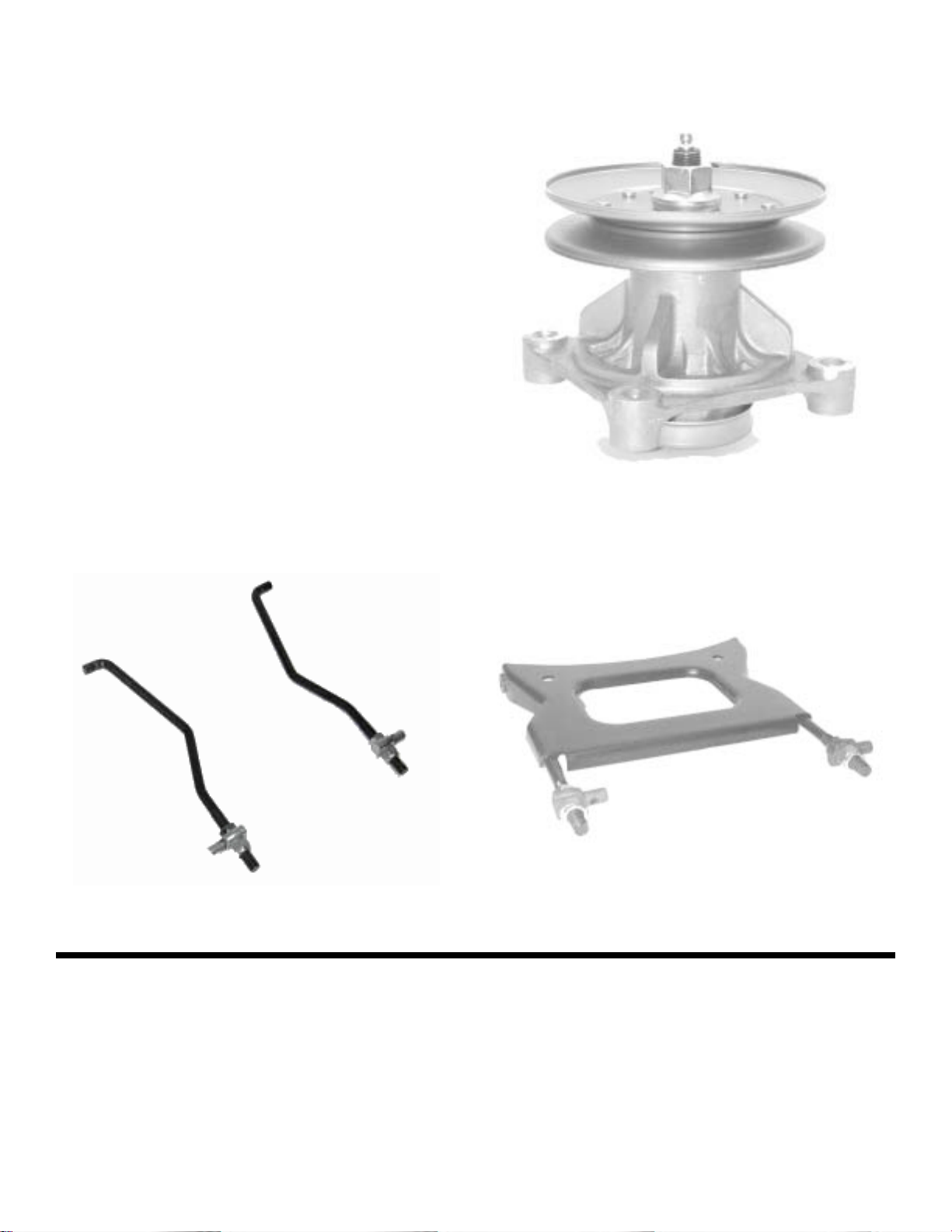
NEW Mandrel for NEW 48” Mower
Two Versions
• Greaseable Bearings
• Sealed Bearings
• Mounted at four points instead of
three on previous mandrels
• Dust Cup
• Blade easier to mount
• Repairable
• Larger 7/16” GR8 Blade Bolt
• Torque blade bolt to 40-50 FtLbs.
• Pulley Nut torqued 55 to 65 Ft.
Lbs.
New Front Mower Suspension for three blade Mowers
Mower Suspension Links
NEW GT Version Front Mower Suspension
176084 Blade for the 46” Mower will replace the 170698 Blade. It will be a thicker
.187” instead of .151”. The new blade will offer improved performance with longer life.
This blade is designed for the customer who does not want to mulch. It will give a
good quality of cut on a lawn or a rough yard without having to change blades.
18
www.mymowerparts.com
Page 19
For Husqvarna Parts Call 606-678-9623 or 606-561-4983
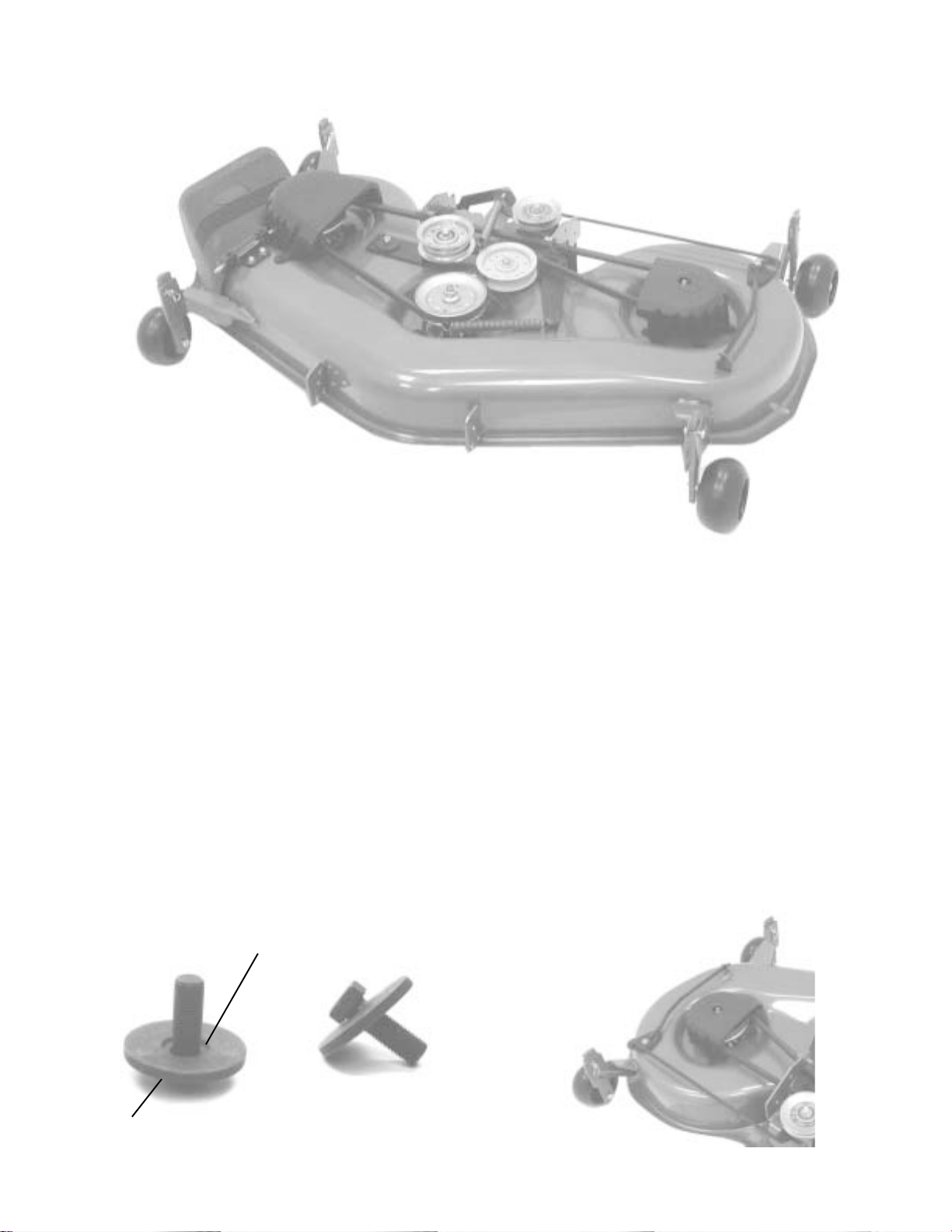
New 48” Heavy Duty Mower
• 10 gauge Heavy Duty Housing
• Heavier Lift Links
• New Front Mower Suspension
• Thicker Blades at .197” from .151”
• Shipped with 173920 Blade for bagging and discharging grass
• Mulching Kit with 173921 Blade optional
• Premium version will have lever to tension the drive belt
Recessed Groove
Belleville Washer
7/16” Bolt
Grade 8
Fine Thread
19
www.mymowerparts.com
Page 20
For Husqvarna Parts Call 606-678-9623 or 606-561-4983
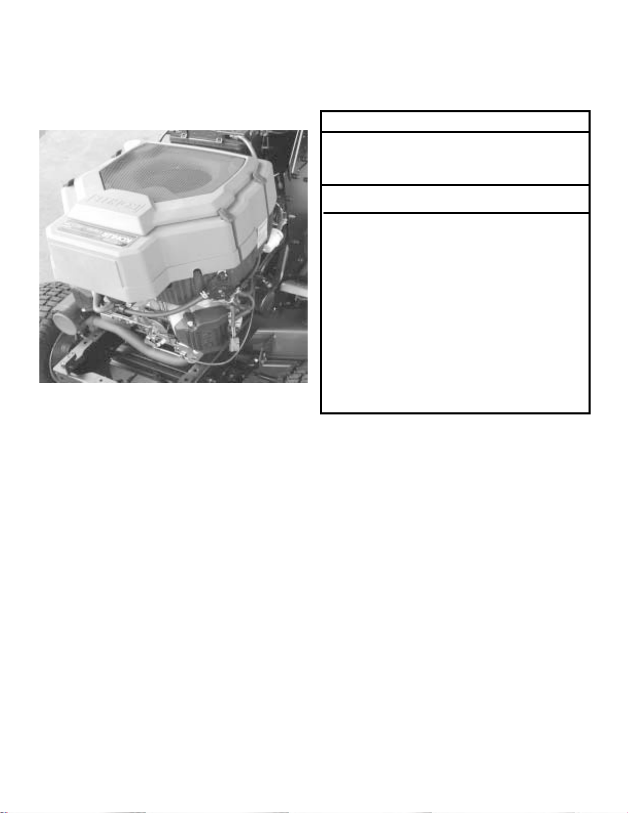
NEW KOHLER ENGINE - LIQUID COOLED TWIN
FEATURES
23 Horsepower V-Twin
Liquid Cooled
Solenoid Shift Starter
ENGINE REQUIREMENTS:
Regular Gasoline
SAE 10W30 Oil above 32degrees F
SAE 5W30 Oil below 32 degrees F
4 pints Engine Oil with new oil filter
3.5 pints Engine Oil w/o new filter
Ethelene Glycol Antifreeze
1.47 quarts Antifreeze Capacity
Antifreeze at 50% with water
Spark Plug Champion RC14YC
Spark Plug Gap 0.030” or 0.76mm
Spark Tester 25-455-01-S
Kohler Engine Service Manual # TP-2509
ENGINE OIL:
Select the SAE oil viscosity grade based on the
expected operation temperature.
Change the Oil every 50 hours of operation or
once a year.
Check the engine oil level before starting the
engine. Remove the dipstick and wipe oil with a
clean cloth. Do not thread the dipstick into the
tube before taking the reading.
ENGINE OIL FILTER:
Replace the engine oil filter once each season
or every other oil change (100 hours) if the oil is
changed more than once a year.
SPARK PLUGS:
Replace spark plugs once each season or
every 100 hours.
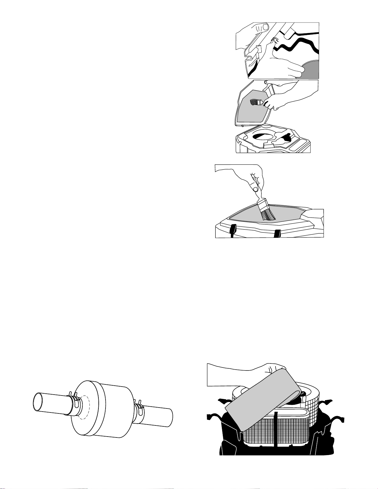
AIR FILTER:
Clean the engine pre-cleaner after every 25
hours of operation or at least once each season.
Use detergent and water to clean the precleaner. Squeeze it dry in a clean cloth. Work
clean engine oil into foam pre-cleaner and remove oil excess by squeezing in a clean dry
cloth.
Change the paper cartridge air filter once each
year or after every 100 hours of operation. DO
NOT wash the paper cartridge air filter.
DO NOT
filter as this will damage the paper element.
use pressurized air to ‘blow out’ the
20
www.mymowerparts.com
Page 21
For Husqvarna Parts Call 606-678-9623 or 606-561-4983
BLOWER HOUSING AND AIR SCREEN
The air screen must be kept clean to prevent
engine damage from overheating. Clean with
compressed air or a brush to remove dirt and
stubborn dried gum fibers. The blower housing
is easily removed after unhooking four retaining
straps.
AIR INTAKE / COOLING
To ensure proper air circulation, make sure the
air intake screen, radiator, cooling fins, and other
external surfaces of the engine are kept clean.
Every 100 hours of operation remove the upper
blower housing assembly. Clean the cooling fins
of the radiator, external surfaces, and the air
intake screen in the blower housing assembly.
The screen assembly may be separated to
permit more thorough cleaning. Make sure all
parts are re-installed before starting the engine.
This may be needed more often in dusty or dirty
conditions.
Cleaning should be done with compressed air
or a soft brush. To avoid damaging the cooling
fins, DO NOT use a pressure washer.
NOTE: Operating the engine with a blocked
intake screen, dirty or plugged radiator cooling
fins, or cooling shrouds removed, will cause
engine damage due to overheating.
IN LINE FUEL FILTER
The fuel filter should be replaced each season.
If the fuel filter becomes clogged, obstructing the
fuel flow to the carburetor, replacement is required.
RADIATOR COOLANT
The coolant should be changed every 1000
hours. See the engine service manual for complete procedure on changing the coolant. Mix
equal parts of ethylene glycol antifreeze and
distilled water for the proper coolant concentration.
The condition of the hoses, clamps, and associated parts should be inspected when exposed
during engine servicing.
NOTE: Properly dispose of old coolant according
to local regulations.
21
www.mymowerparts.com
Page 22
For Husqvarna Parts Call 606-678-9623 or 606-561-4983
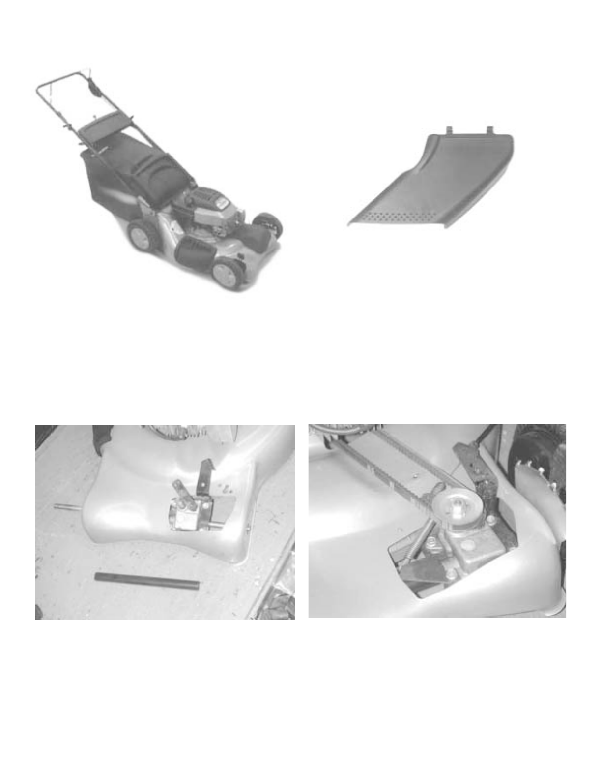
NEW 21” FRONT WHEEL GEAR DRIVE MOWER
• 21 inch cut
• Rear Discharge
• Side Discharge Deflector
• Mulcher Plug in rear door
• Welded Baffles
• Self Tapping screws
DRIVE SYSTEM COMPONENTS ARE LIKE 22’’ MODELS
BLADES for 21” Front Drive only
175064 REGULAR STEEL MULCH / BAG / DISCHARGE
176135 PREMIUM STEEL MULCH / BAG / DISCHARGE
175052 REGULAR STEEL MULCH only
22
www.mymowerparts.com
Page 23
For Husqvarna Parts Call 606-678-9623 or 606-561-4983
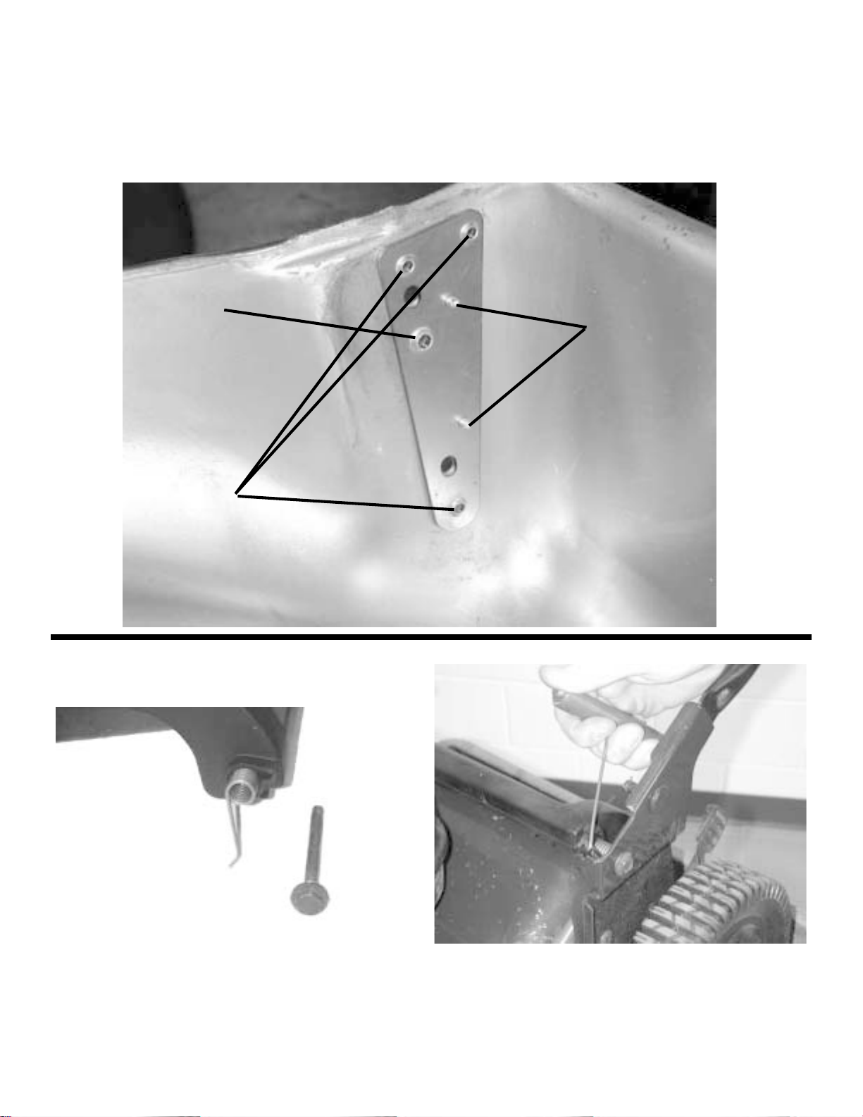
There will be extruded holes in reinforcing plates for self tapping screws used for the
Handle Brackets and the Rear Wheel Adjusters. The brackets will be pop riveted to
the housing to assist ease of assembly. Models with high wheels will use the wheel
adjuster bolt hole for another self tapping screw and additional support to the handle
bracket.
Extruded Holes
for wheel adjuster
bolt.
Pop Rivets
Extruded Hole for
Handle Bracket
Screws
• Rear door springs are easily replaceable
• A spring fits into each side of the rear door at the hinge.
• Install the bolt that holds the rear door to the handle brackets
• Use a hook to load the door springs against the handle bracket tabs.
23
www.mymowerparts.com
Page 24
For Husqvarna Parts Call 606-678-9623 or 606-561-4983
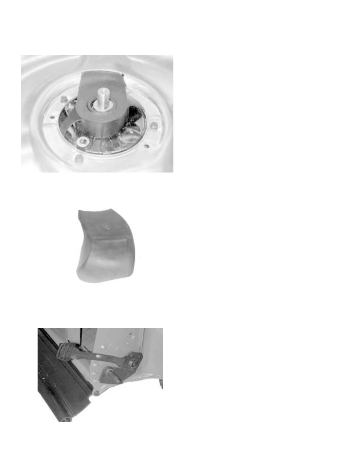
BELT COVER INSTALLATION
• Install the drive pulley .130” from
engine, place belt on pulley and
#1
through opening in deck
• Insert Belt Cover into opening in
deck for belt #1
#3
#2
• Insert right tab beween housing
and engine #2
• Push left leg of belt cover so that
it is under edge of housing #3
DRIVE COVER INSTALLATION
• Insert two tabs at end of cover
into housing belt opening
• Locating tabs on the front of the
Drive Cover will position over the
transmission opening
• Install screw to secure Drive
Cover
REAR WHEEL ADJUSTER IMPROVEMENTS
• Sector Plate formed into handle
brackets
• Belleville Washer eliminated with
form of selector lever
• Pal nut holds parts onto shoulder
bolt for easy assembly
• Recessed area in spacer washer
for pal nut
• Self tapping shoulder bolt eliminates nut inside housing
• Longer selector spring levers
24
www.mymowerparts.com
Page 25

For Husqvarna Parts Call 606-678-9623 or 606-561-4983
Touch - Up Paints for Lawn & Garden
PART No. DESCRIPTION PAINT CODE
177392 RED LTX, Spray Paint 615
175247 DESERT GOLD Spray Paint 612
175246 STORM GRAY Spray Paint 613
169696 ANTIQUE SAGE Spray Paint 598
169695 ANNIVERSARY RED Spray Paint 603
169694 FOREST GREEN Spray Paint 602
150131 SATIN BLACK Spray Paint
150020 POLO GREEN Spray Paint (SEARS) 558
144401 GREEN Spray Paint 550
136247 RED Spray Paint 505, 506, 394, 423
136246 BLUE (Dark) Spray Paint 510, 511
130939 GREEN ( POULAN ) Spray Paint 419
130937 DOVER GRAY Spray Paint 459, 478
161394 HIGH GLOSS BLACK Spray Paint 428
126967X NEW SEARS SILVER Spray Paint 417
126966X GRAY Spray Paint( Husqvarna/WA) 410, 418
126965X ORANGE Spray Paint Husqvarna) 412, 422
NOTE: The paint code can be matched to the end of the part number for painted parts needing touch-up.
25
www.mymowerparts.com
Page 26
For Husqvarna Parts Call 606-678-9623 or 606-561-4983
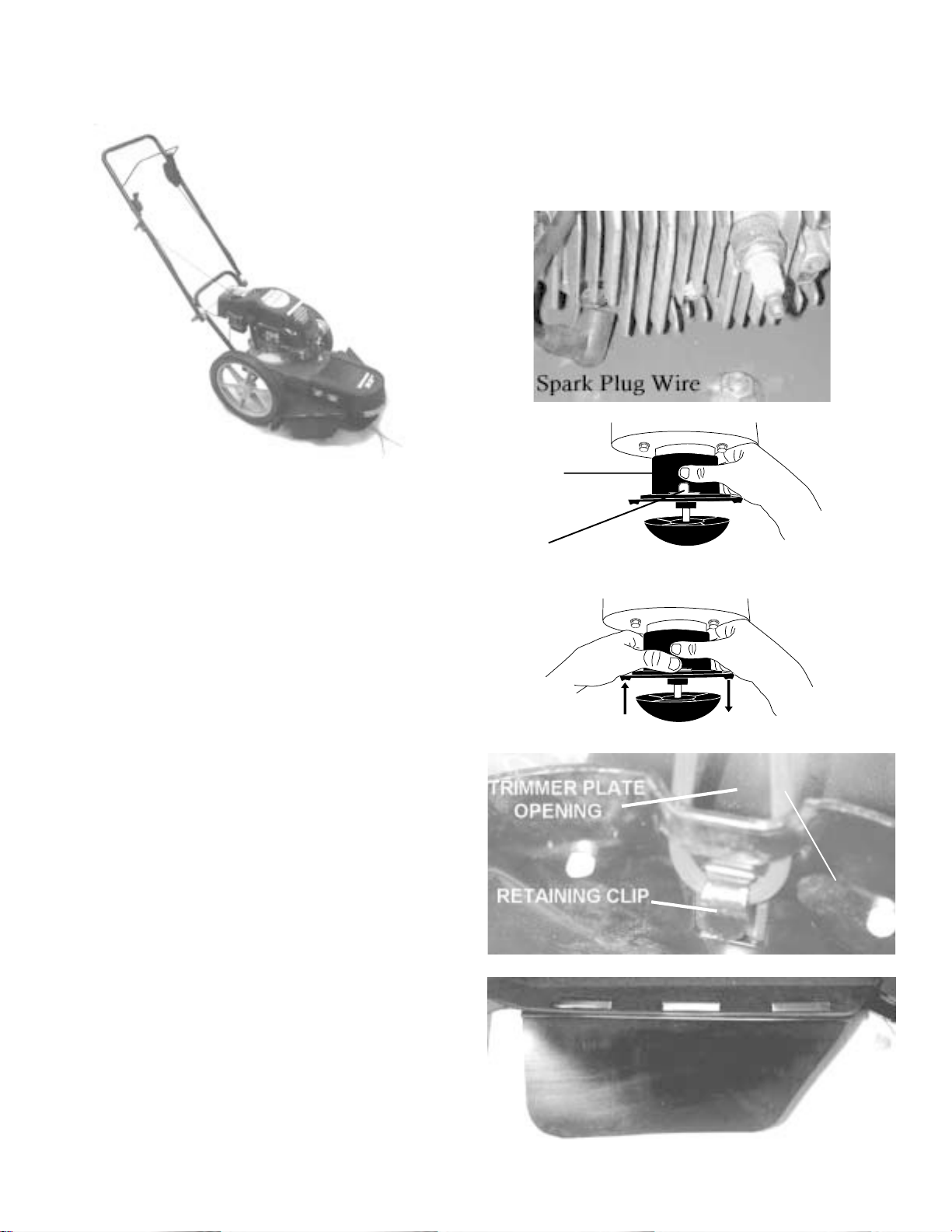
WEED TRIMMER from ELECTROLUX Home Products
While servicing a weed trimmer, remove the wire
from the spark plug and secure the wire in a
position where it cannot contact the spark plug.
Adjusting
Trimmer
There are two head assemblies used, one is
adjustable with from 1.5 to 3 inches of height and
the other is a fixed height. You will find a Locking
Plate Tab on the adjustable head. When the Tab
is depressed, the trimmer head can be moved to
the desired position.
Head
Locking
Plate Tab
Use .155 inch diameter Trimmer Line that is cut
to 18 ¾ inches in length before installing.
To install, fold the trimmer line in half. Push the
folded end through the opening in the trimmer
plate and over the retainer clip. Pull the trimmer
line into the retainer clip to lock it in place. It is
important that after trimmer lines are installed,
that the length is checked or an unbalanced
condition may occur. The length of all lines must
not vary by more than one inch.
There is a cover on the engine secured by one
knob for easy access. The screen inside the
cover as well as the engine air intake screen
should be cleaned during routine servicing.
There is a Skirt at the left front corner of the
Debris Shield. It should be replaced if damaged.
TRIMMER
LINE
SKIRT
26
www.mymowerparts.com
Page 27
For Husqvarna Parts Call 606-678-9623 or 606-561-4983
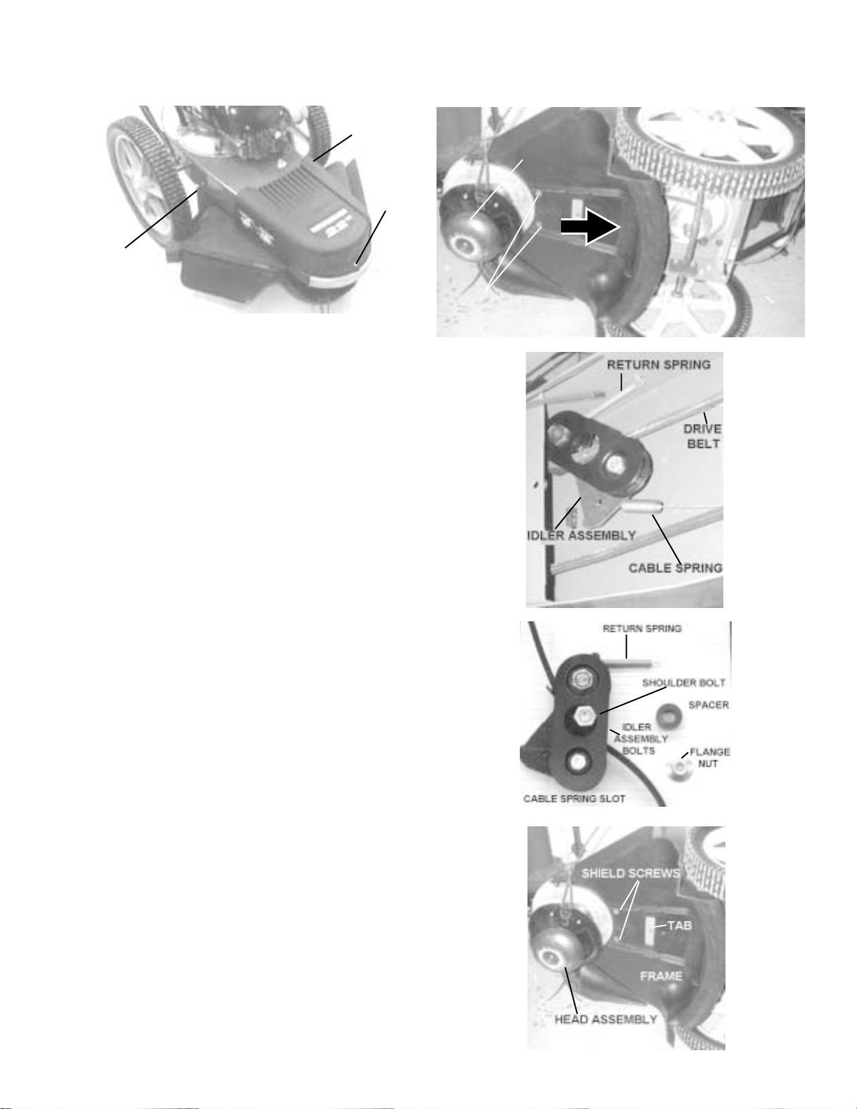
BELT REPLACEMENT PROCEDURE
SHIELD
SCREW
COVER
SCREW
SHIELD
SCREW
• Remove the spark plug wire and secure away from the
spark plug
• Remove the Cover Screw to access the belt at the
front pulley
• Remove the Screw on each side holding the Shield by
the wheels
• Place weed trimmer on side with air filter up.
• Remove the two Shield Screws on underside by the
head
• Pull Debris Shield toward the rear of the as shown by
arrow
• Remove Drive Belt from Engine Pulley and Pulley on
the Head Assembly.
• Remove the Return Spring from the chassis of the
weed trimmer
• Remove the Cable Spring from the idler bracket
• Remove shoulder bolt holding idler assembly and belt
to chassis. Move belt to get socket on the head of the
shoulder bolt. Hold Flange Nut of top of chassis while
loosening the shoulder bolt.
• Install new Drive Belt in Idler Assembly
• To reinstall Idler Assembly, place Shoulder Bolt
through Idler Assembly, Spacer, and Chassis. Loosely
attach Flange Nut on top of the chassis.
• Install the Return Spring into the notch in Chassis side
• Install the engagement cable Spring into the Idler
Assembly Bracket from the underside, so it is trapped
between the chassis and the bracket.
• Tighten the Flange Nut and Shoulder Bolt.
• Install the Drive Belt on the front Head Assembly Pulley
and then on the Engine Pulley.
• Install the Debris Shield. Line up the tab on the chassis
side and the front edge between chassis and the head
assembly and push forward until the screw holes line
up. Install the two Shield Screws on underside.
• Install Shield Screws either side of the chassis
• Install the Screw in the front Cover
• Replace the Wire on the Spark Plug
SHIELD
SCREWS
27
HEAD
ASSEMBLY
www.mymowerparts.com
Page 28
For Husqvarna Parts Call 606-678-9623 or 606-561-4983
21” Rear Wheel Gear Drive Adjustment and
Troubleshooting
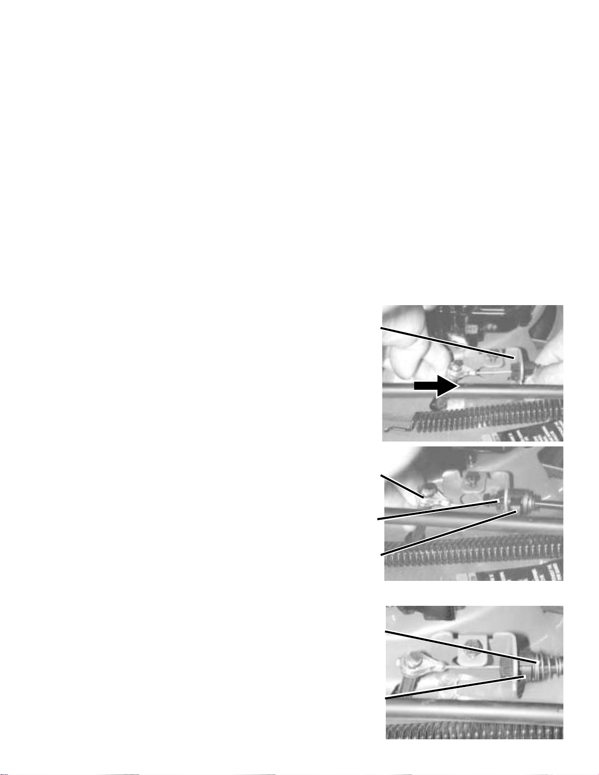
Anytime the Speed Cable is disassembled or the drive pulley under the deck is disturbed, the adjustment procedure should be performed.
CAUTION: Disconnect the Spark Plug Wire before working on the mower.
Procedure to Adjust Speed Control Cable and to Install the Speed Control Cable.
1. Move the lever on the speed control cable to the slowest position before installing onto the handle.
2. Install the Cable End over the end of the Pivot Rod at the side of the engine. Snap the cable
Fitting into the housing Bracket. Do NOT lock in the Adjustment Tab.
3. Set the Speed Lever to one notch below the fastest speed.
4. Hold down the engine control bail and pull starter rope through to rotate engine several revolutions
to seat the drive belt under the deck.
DANGER: The BLADE is turning when this step is performed. The mower must be upright; and
care must be taken to keep any object from coming in contact with the blade, especially hands and
feet
5. Pull all slack from the speed control fitting by
pushing lightly on the Pivot Rod, toward the
housing Bracket. Snap the Adjustment Tab into
place.
6. Return the speed lever to the low speed
position.
This is NOT CORRECT. If slack is found in the
cable, it is NOT properly adjusted. Repeat step
#5.
NOTE: The Adjustment Tab at the side of the
cable is not yet locked in place. The cable
fitting is locked into the housing bracket.
This shows the correct adjustment, with the
Adjustment Tab locked in and no slack in the
cable.
NOTE: The cable adjustment spring is not
necessarily collapsed after the adjustment.
Housing
Bracket
Cable End
Cable
Fitting
Adjustment
Tab
Adjustment
Spring
Tab
28
www.mymowerparts.com
Page 29
For Husqvarna Parts Call 606-678-9623 or 606-561-4983
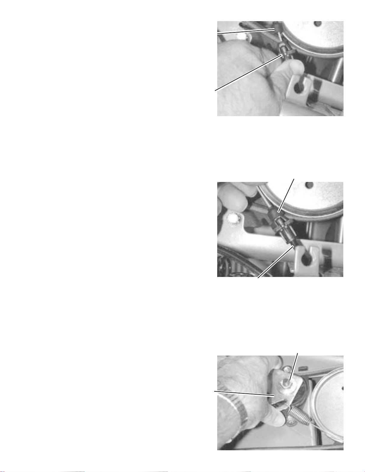
7. The fitting on the Speed Control Cable End,
should be securely attached to this bracket.
Inspect the Belt Keeper Bracket, speed control
Cable Holding Arm to see if it is at a 90 degree
upright position. If the angle is other than 90
degrees, adjust this arm.
8. The rubber boot should be in this position
to protect the cable from debris and moisture.
Also check the condition of the cables at the
middle of the handle. If the cables have been
damaged, they may not be able to move into the
proper position.
Boot
Brake
Gear Box
Pulley
Boot
9. Check the movement of the idler bracket. It
should travel from the deck tunnel to the engaged belt position. Check in both the fastest
and slowest speed positions. It may be necessary to loosen the flange nut slightly to get the
idler bracket to smoothly travel across the
needed range of movement.
10. It is difficult to tell if the speed has changed
as you move the speed lever, because the
speed differences are so small. It is best to
remove the cover over the idler pulleys while
evaluating the drive speeds. You should see a
different idler bracket position when you move
the speed lever.
Engagement
Cable
Flange Nut
Idler
Bracket
29
www.mymowerparts.com
Page 30
For Husqvarna Parts Call 606-678-9623 or 606-561-4983
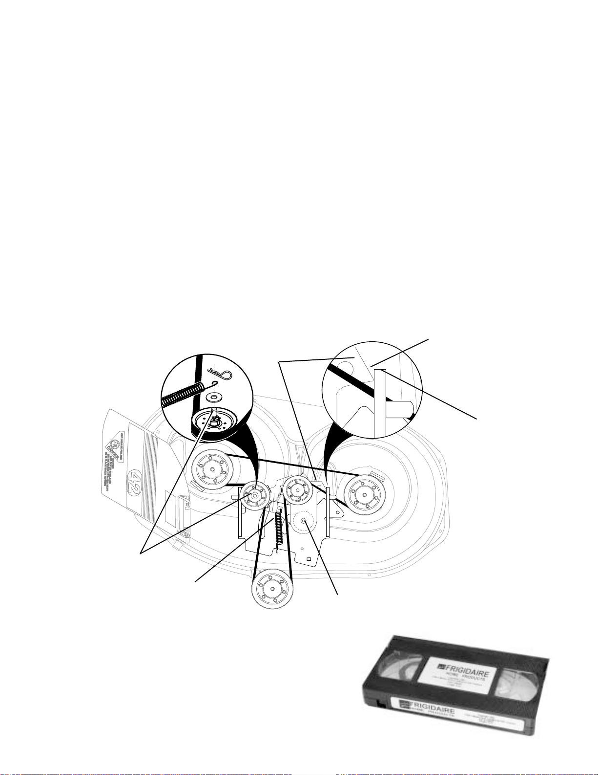
PROBLEM: REPEATED PROBLEM WITH MOWER CABLE CLUTCH FAILURE AT CABLE SPRING
SOLUTION: INSTALL 42” MOWER CABLE CLUTCH REPLACEMENT KIT #175067
CLUTCH CABLE REPLACEMENT
KIT NO. 175067 FOR 42 INCH MOVER
KIT CONTENTS:
(1) 169676 Clutch Cable
(1) 173443 Carriage Bolt (Special)
(1) 7192J Cable Tie
INSTALLATION INSTRUCTIONS
1. Remove the mower from tractor (See Tractor Owner's Manual for instructions).
2. Remove and discard clutch cable from tractor. Note the location of the cable tie.
3. Assemble new clutch cable to tractor. Secure cable to right side of chassis with the cable tie provided in kit.
REPLACE CLUTCHING IDLER CARRIAGE BOLT
4. Disconnect idler return spring from idler arm.
5. To access carriage bolt, remove nut and bolt "A" securing idler brackets to mower deck.
6. Remove and replace clutching idler carriage bolt "B" with carriage bolt supplied in kit.
7. Reassemble idler brackets to mower deck.
IMPORTANT: After tightening nut and bolt "A", the fixed idler bracket "C" must be tight and flush against mower hanger
bracket (Max. 1/16" clearance) and the clutching idler arm must move freely.
8. Reconnect idler return spring to idler arm.
9. Properly position belt on mower and install mower to tractor (See Tractor Owner's Manual for instructions).
FLUSH TO 1/16" MAX.
FIXED IDLER
BRACKET "C"
CLEARANCE
REPLACE
CLUTCHING IDLER
CARRIAGE BOLT "B"
IDLER RETURN
SPRING
AVAILABLE TECHNICAL INFORMATION
163578 MANUAL, Tractor and Rear Tine Tiller
163579 MANUAL, Mower and Front Tine Tiller
173699 MANUAL, 2000 Sears Product Accessories
174702 MANUAL, 2000 Sears Electrical Schematics
168695 VIDEO, FHP Mower Leveling
169287 VIDEO, FHP ‘Automatic’ Drive Servicing
MOWER HANGER
BRACKET
REMOVE
NUT AND BOLT "A"
30
www.mymowerparts.com
Page 31

For Husqvarna Parts Call 606-678-9623 or 606-561-4983
NOTES
31
www.mymowerparts.com
Page 32

For Husqvarna Parts Call 606-678-9623 or 606-561-4983
Printed in U.S.A. 177868 12/21/00 VFH
www.mymowerparts.com
 Loading...