

Page 1

For Husqvarna Parts Call 606-678-9623 or 606-561-4983
Husqvarna Chain Saws
Workshop Manual
101 88 55-26
www.mymowerparts.com
Page 2

For Husqvarna Parts Call 606-678-9623 or 606-561-4983
LIST OF CONTENTS
Introduction ..................................... 3
Safety regulations ........................... 5
Technical Data ................................. 6
Tools............................................... 14
Service data ................................... 20
Trouble shooting ........................... 40
Safety equipment .......................... 42
Starter............................................. 57
Electrical system........................... 61
Centrifugal clutch.......................... 67
Lubrication system ....................... 70
Carburettor..................................... 83
Air filter ........................................ 101
Tank unit....................................... 103
Anti-vibration system.................. 106
Piston cylinder............................. 108
Crankcase and crankshaft.......... 114
2 – English
www.mymowerparts.com
Page 3

For Husqvarna Parts Call 606-678-9623 or 606-561-4983
INTRODUCTION
General Updates
This workshop manual provides a detailed description of procedures for trouble shooting, repair
and testing of the chain saws. Safety precautions
that should be taken during repair are also
described.
This workshop manual applies to the engine
assembly in the following chain saws:
36
40
257
262XP
268
41
42
272XP
268K
45
51
272K
272S
55
61
281XP
288XP
242XP
246
254XP
394XP
3120XP
As production continues, changes will be introduced successively to the chain saw. If at any
time these changes influence service and/or
spares, special service announcements will be
sent out, which means that this manual will cease
to be current with time. In order to avoid problems, the manual should always be read together
with all service announcements that apply to the
specific model of chain saw.
Tools
For specific procedures special tools are required. In this workshop manual, all the service
tools required are listed. Use of the tools is
described in appropriate sections.
Always use Husqvarna original:
• Spare parts
• Service tools
• Accessories
Safety
Note!
The section dealing with safety should be
read and understood by all who carry out
repair or service work on the chain saw.
There are warning symbols on the chain saw. If a
warning symbol has been damaged or is missing,
it must be replaced immediately in order to
maximise safety when the saw is in use.
Target group
This workshop manual is written for personnel
that are assumed to have general knowledge of
service and repair of small engines.
The workshop manual should be read and understood by all personnel carrying out service and
repair work on the chain saw. The manual is also
suitable for use in the training of new employees.
Layout
The descriptive sections in this workshop manual
are set out in a number of flow diagrams. When
carrying out repairs on a specific chain saw,
follow the signs that apply to the saw in question.
Diagrams are not numbered as they are linked to
the actual text, either by lines or by being in the
same box.
Positional directives to components inside the
diagrams are designated with A, B, etc. and start
from A again in each new section.
www.mymowerparts.com
English – 3
Page 4

For Husqvarna Parts Call 606-678-9623 or 606-561-4983
INTRODUCTION
Use
This workshop manual can be used in two different
ways:
• Repair of a specific sub-assembly
• Dismantling and reassembly of the entire chain
saw
Repair of a specific sub-assembly
When a specific sub-assembly on the chain saw is
to be repaired, proceed as follows:
1. Refer to the page referring to the relevant subassembly.
2. Carry out the steps: Dismantling
Cleaning and inspection
Reassembly
Dismantling and reassembly of the entire
chain saw
When the entire chain saw is to be dismantled
and reassembled, proceed as follows:
1. Refer to page 57, which deals with the
Starter and carry out the instructions
under the heading Dismantling.
2. Work forwards through the manual and
carry out Dismantling instructions in the
order that the sections occur.
3. Return to the Starter on page 58 and
follow the instructions under Cleaning
and Inspection.
4. Work forward through the manual and
carry out Cleaning and Inspection in the
order that the sections occur.
5. Order or collect all the required spare
parts from the spare parts stores.
6. In order to Assemble the chain saw,
proceed as follows:
• Refer to pages 117-120 which deals with
the Crankcase and carry out the instructions under Assembly.
• Refer to pages 111-112 which deals with
the Piston and Cylinder and carry out
the instructions under Assembly.
• Refer to pages 107 which deals with the
Anti-vibration system and carry out the
instructions under Assembly.
• Refer to page 105 which deals with the
Tank unit and carry out the instructions
under Assembly.
Continue to work backwards through the
manual and carry out Assembly instructions
as the sections occur.
In order to improve understanding, some
sections begin with a Description of the
relevant sub-assembly.
4 – English
www.mymowerparts.com
Page 5

For Husqvarna Parts Call 606-678-9623 or 606-561-4983
SAFETY REGULATIONS
General Instructions
Workshops where chain saws are serviced
must be equipped with safety equipment
as set out in local directives.
No one should repair a chain saw without
first having read and understood the
contents of this workshop manual.
The following warning texts are to be found
in this manual in certain places. The
warning texts occur before the procedure
to which they refer.
WARNING!
!
The warning text indicates a risk
of personal injury if instructions
are not followed.
Special instructions
The fuel used in the chain saw poses the
following hazards:
1. The fluid and its fumes are poisonous.
2. Can cause eye and skin irritation.
3. Can cause breathing difficulties
4. Is highly inflammable.
The bar, chain and clutch cover (chain
brake) must be assembled before the
chain saw is started, otherwise the clutch
may come loose causing personal injury.
Wear ear muffs when testing the chain
saw.
Do not use the saw until it has been
adjusted so that the chain does not rotate
when idling.
Bear in mind the fire risk. The saw can
produce sparks that can cause a fire hazard..
NOTE!
The warning text indicates a risk of
damage to equipment if instructions
are not followed.
The chain saw is type approved with
regard to safety according to applicable
legal requirements when fitted with the
cutting equipment specified in the
Operator's Manual. Equipping the saw with
other equipment or accessories and spare
parts not approved by Husqvarna can
result in non compliance with these safety
requirements and liability for persons
carrying out such modifications.
After testing, do not touch the
silencer until it has cooled. Risk
1
the saw is fitted with a catalytic converter.
The coating on and in the catalytic element
is hazardous to touch. Use protective gloves
when working on the catalytic converter.
Inadequate chain lubrication can result in
the chain breaking, which can cause
serious or fatal injury.
tension before the cord pulley is removed.
tension, otherwise the spring can fly out
causing personal injury.
After repair, the chain brake must be
checked in accordance with the
instructions on page 47.
of burns. This especially applies if
Make sure that the starter recoil
spring does not fly out and cause
personal injury. Release the spring
When removing the pressure
spring for the chain brake, ensure
that the brake is in the 'on'
position which reduces the spring
When replacing the crankshaft bearings
note that the crankcase halves are hot.
Use protective gloves.
When using compressed air, the air jet
should never be pointed towards the body.
Air can be forced into the blood stream,
which can cause fatality.
www.mymowerparts.com
English – 5
Page 6

For Husqvarna Parts Call 606-678-9623 or 606-561-4983
TECHNICAL DATA
Displacement Bore Stroke Max. power at
cm
36 36 38.0 32.0 9000
40 40 40.0 32.0 9000
41 40 40.0 32.0 9000
42 42 42.0 30.0 9300
45 44 42.0 32.0 9000
51 51 45.0 32.0 9000
3
mm mm r/min
Spark plug gap Ignition system Air gap Carburettor
mm/inches mm/inches
36 0.5/ .02 PHELON 0.3/ .012 WALBRO WT 239
40 0.5/ .02 PHELON 0.3/ .012 ZAMA C1Q-EL1
41 0.5/ .02 PHELON 0.3/ .012 WALBRO WT 239
42 0.5/ .02 SEM AM 7 0.3/ .012 WALBRO HDA 98
45 0.5/ .02 PHELON 0.3/ .012 ZAMA C1Q-EL1
51 0.5/ .02 ELECTROLUX ET 0.3/ .012 WALBRO WT 170
Bar length Chain speed Chain pitch Drive link gauge
cm/inches m/s inches mm/inches
36 33-46/13-18 17.3/9000 rpm .325-3/8 1.3/ .050
40 33-46/13-18 17.4/8500 rpm .325 1.3/ .050
41 33-46/13-18 17.3/9000 rpm .325-3/8 1.3/ .050
42 28-46/11-18 17.9/9300 rpm .325 1.5/ .058 / 1.3/ .050
45 33-46/13-18 17.4/8500 rpm .325 1.3/ .050
51 33-51/13-20 17.4/9000 rpm .325-3/8 1.5/ .058 / 1.3/ .050
1)
From May 1996
6 – English
www.mymowerparts.com
1)
1)
Page 7

For Husqvarna Parts Call 606-678-9623 or 606-561-4983
TECHNICAL DATA
Idling speed Engagement speed Max. speed Spark plug
r/min r/min r/min Champion
36 3000 4500 13000 RCJ 7 Y
40 2500 3600 12500 RCJ 7 Y
41 3000 4500 13000 RCJ 7 Y
42 2700 3800 14500 RCJ 7 Y
45 2500 3600 12500 RCJ 7 Y
51 2500 3700 12500 RCJ 7 Y
Fuel tank volume Oil pump capacity Oil tank volume Automatic oil pump
Litres cm
36 0.4 7 0.2 Yes
40 0.5 8 0.25 Yes
41 0.4 7 0.2 Yes
42 0.5 3-7 0.27 Yes
45 0.5 8 0.25 Yes
51 0.6 10 0.3 Yes
Weight without bar and chain Weight with bar and chain Handle heater
kg kg/lbs Watt/ r/min
36 4.6 5.3 (13") No
40 4.7 5.4 (13") No
41 4.6 5.3 (13") No
3
/min at 8.500 rpm Litres
42 4.7 5.5 (13") No
45 4.7 5.4 (13") No
51 5.2 6.2 (15") No
www.mymowerparts.com
English – 7
Page 8

For Husqvarna Parts Call 606-678-9623 or 606-561-4983
TECHNICAL DATA
Displacement Bore Stroke Max. power at
cm
55 53 46.0 32.0 9000
61 62 48.0 34.0 8300
242XP 42 42.0 30.0 9900
246 46 44.0 30.0 9000
254XP 54 45.0 34.0 9300
257 57 46.0 34.0 9000
3
mm mm r/min
Spark plug gap Ignition system Air gap Carburettor
mm/inches mm/inches
55 0.5/ .02 ELECTROLUX ET 0.3/ .012 WALBRO WT 170
61 0.5/ .02 ELECTROLUX ET 0.3/ .012 TILLOTSON HS 254
242XP 0.5/ .02 SEM AM 7 0.3/ .012 WALBRO HDA 98
246 0.5/ .02 SEM AM 7 0.3/ .012 WALBRO HDA 98
254XP 0.5/ .02 ELECTROLUX ET 0.3/ .012 WALBRO HDA 35B
257 0.5/ .02 ELECTROLUX ET 0.3/ .012 WALBRO HDA 120
Bar length Chain speed Chain pitch Drive link gauge
cm/inches m/s inches mm/inches
55 38-51/15-20 17.4/9000 rpm .325-3/8 1.5/ .058 / 1.3/ .050
61 38-51/15-20 18.4/8300 rpm 3/8 1.5/ .058
242XP 28-46/11-18 19.1/9900 rpm .325 1.5/ .058 / 1.3/ .050
1)
1)
246 28-46/11-18 17.3/9000 rpm .325 1.5/ .058 / 1.3/ .050
254XP 33-51/13-20 17.3/9300 rpm .325-3/8 1.5/ .058
257 33-51/13-20 17.3/9000 rpm .325-3/8 1.5/ .058
1) From May 1996
8 – English
www.mymowerparts.com
1)
Page 9

For Husqvarna Parts Call 606-678-9623 or 606-561-4983
TECHNICAL DATA
Idling speed Engagement speed Max. speed Spark plug
r/min r/min r/min Champion
55 2500 3700 12500 RCJ 7 Y
61 2500 3700 12000 RCJ 7 Y
242XP 2700 3900 15500 RCJ 7 Y
246 2700 3900 15000 RCJ 7 Y
254XP 2700 3700 13800 RCJ 7 Y
257 2700 3700 13500 RCJ 7 Y
Fuel tank volume Oil pump capacity Oil tank volume Automatic oil pump
3
Litres cm
55 0.6 10 0.3 Yes
61 0.75 4/8/12/17 0.45 Yes
242XP 0.5 3-7 0.27 Yes
246 0.5 3-7 0.27 Yes
254XP 0.6 3-10 0.3 Yes
257 0.6 3-10 0.3 Yes
Weight without bar and chain Weight with bar and chain Handle heater
kg kg/lbs Watt/ r/min
55 5.2 6.2 (15") No
61 6.1 7.1 (15") No
242XP 4.7 5.5 (13") 65/10.000
/min at 8.500 rpm Litres
246 4.7 5.5 (13") No
254XP 5.4 6.3 (13") 65/10000
257 5.6 6.6 (13") 65/10000
www.mymowerparts.com
English – 9
Page 10

For Husqvarna Parts Call 606-678-9623 or 606-561-4983
TECHNICAL DATA
Displacemennt Bore Stroke Max. power at
cm
262XP 62 48.0 34.0 9600
268 67 50.0 34.0 9000
272XP 72 52.0 34.0 9300
268K 67 50.0 34.0 9000
272K 72 52.0 34.0 9300
272S 72 52.0 34.0 9300
3
mm mm r/min
Spark plug gap Ignition system Air gap Carburettor
mm/inches mm/inches
262XP 0.5/ .02 ELECTROLUX ET 0.3/ .012 WALBRO HDA 120
268 0.5/ .02 ELECTROLUX ET 0.3/ .012 TILLOTSON HS 260
272XP 0.5/ .02 ELECTROLUX ET 0.3/ .012 TILLOTSON HS 260
268K 0.5/ .02 ELECTROLUX ET 0.3/ .012 TILLOTSON HS 255
272K 0.5/ .02 ELECTROLUX ET 0.3/ .012 TILLOTSON HS 255
272S 0.5/ .02 ELECTROLUX ET 0.3/ .012 TILLOTSON HS 255
Bar length Chain speed Chain pitch Drive link gauge
cm/inches m/s inches mm/inches
262XP 33-51/13-20 18.5/9600 rpm .325-3/8 1.5/ .058
268 38-51/15-20 18.4/9000 rpm 3/8 1.5/ .058
272XP 38-51/15-20 20.0/9300 rpm 3/8 1.5/ .058
268K - - - 272K - - - 272S - - - -
10 – English
www.mymowerparts.com
Page 11

For Husqvarna Parts Call 606-678-9623 or 606-561-4983
TECHNICAL DATA
Idling speed Engagement speed Max. speed Spark plug
r/min r/min r/min Champion
262XP 2700 3400 13500 RCJ 7 Y
268 2500 3500 12500 RCJ 7 Y
272XP 2500 3500 13500 RCJ 7 Y
268K 2500 3500 10000 RCJ 7 Y
272K 2500 3500 10000 RCJ 7 Y
272S 2500 3500 10000 RCJ 7 Y
Fuel tank volume Oil pump capacity Oil tank volume Automatic oil pump
3
Litres cm
262XP 0.6 6.5-13.5 0.3 Yes
268 0.75 4/9/13/17 0.45 Yes
272XP 0.75 5/9/14/19 0.45 Yes
268K 0.75 - - 272K 0.75 - - 272S 0.75 - - -
Weight without chain and bar Weight with chain and bar Handle heater
kg kg/lbs Watt/ r/min
262XP 5.8 6.8 (13") 65/10000
268 6.2 7.2 (15") 65/10000
272XP 6.3 7.3 (15") 65/10000
/min at 8.500 rpm Litres
268K 9.5 - 272K 9.6 - 272S 21.0 (including carriage) - -
www.mymowerparts.com
English – 11
Page 12

For Husqvarna Parts Call 606-678-9623 or 606-561-4983
TECHNICAL DATA
Displacement Bore Stroke Max. power at
cm
281XP 81 52.0 38.0 9000
288XP 87 54.0 38.0 9300
394XP 94 56.0 38.0 8800
3120XP 119 60.0 42.0 9000
3
mm mm r/min
Spark plug gap Ignition system Air gap Carburettor
mm/inches mm/inches
281XP 0.5/ .02 SEM AM 7 0.3/ .012 TILLOTSON HS 228
288XP 0.5/ .02 SEM AM 7 0.3/ .012 TILLOTSON HS 228
394XP 0.5/ .02 SEM AM 44 0.3/ .012 WALBRO WJ 39
3120XP 0.5/ .02 SEM AM 37 0.3/ .012 WALBRO WG 6
Bar length Chain speed Chain pitch Drive link gauge
cm/inches m/s inches mm/inches
281XP 38-71/15-28 20.0/9000 rpm 3/8 1.5/ .058
288XP 38-71/15-28 20.7/9300 rpm 3/8 1.5/ .058
394XP 46-91/18-36 19.6/8800 rpm 3/8-.404 1.5/ .058 - 1.6/.063
3120XP 60-107/24-42 20.1/9000 rpm .404 1.6/ .063
12 – English
www.mymowerparts.com
Page 13

For Husqvarna Parts Call 606-678-9623 or 606-561-4983
TECHNICAL DATA
Idling speed Engagement speed Max. speed Spark plug
r/min r/min r/min Champion
281XP 2500 3200 12500 RCJ 6 Y
288XP 2500 3200 12500 RCJ 6 Y
394XP 2500 3400 12500 RCJ 6 Y
3120XP 2500 3300 11500-12500 RCJ 7 Y
Fuel tank volume Oil pump capacity Oil tank volume Automatic oil pump
3
Litres cm
281XP 0.9 9/12/15/18 0.5 Yes
288XP 0.9 9/12/15/18 0.5 Yes
394XP 0.9 14-21 0.5 Yes
3120XP 1.25 8-51 0.7 Yes
Weight without bar and chain Weight with bar chain Handle heater
kg kg/lbs Watt/ r/min
281XP 7.5 8.7 (18") 56/7200
288XP 7.5 8.7 (18") 56/7200
/min at 8.500 rpm Litres
394XP 7.9 9.2 (18") 65/10000
3120XP 10.4 12.3 (28") No
www.mymowerparts.com
English – 13
Page 14

For Husqvarna Parts Call 606-678-9623 or 606-561-4983
TOOLS
Tools for all chain saws
502 50 57-01 3/16"
502 50 16-01 6 mm
502 50 64-01 5 mm
502 50 18-01 4 mm
502 50 19-01 3 mm
502 50 88-01 5 mm
502 50 87-01 4 mm
502 50 86-01 3 mm
502 71 13-01
502 50 22-01 8 mm
502 50 23-01 10 mm
502 51 34-02 (0,3 mm)
compl 502 50 70-01
502 51 91-01 (0,5 mm)
502 50 06-01
502 50 37-01
502 70 09-01
504 98 26-01
(36, 41, 40, 45)
502 50 83-01
14 – English
502 51 02-01
502 71 14-01
www.mymowerparts.com
Page 15

For Husqvarna Parts Call 606-678-9623 or 606-561-4983
TOOLS
Tools for saws 36 and 41 Tools for saws 40, 45, 51 and 55
3 mm; 4 mm; 5 mm
8 mm; 10 mm
530 03 11-12
502 51 94-01
502 51 00-02
502 50 33-01
530 03 11-36
4 mm
8 mm
40 > 910 1116
45 > 925 1168
50 > 925 0856
502 50 99-01
(55)
502 51 61-01
(51, 55)
505 26 79-12
502 50 33-01
502 50 26-01
(55)
502 51 94-01
505 38 18-17
(40. 45)
504 90 90-01
502 50 30-09
40 > 910 1116
45 > 925 1168
504 90 29-02
502 50 79-01 (55)
compl 502 50 38-01
502 54 03-01
(40, 45, 55)
502 50 46-01
(55)
www.mymowerparts.com
English – 15
Page 16
For Husqvarna Parts Call 606-678-9623 or 606-561-4983
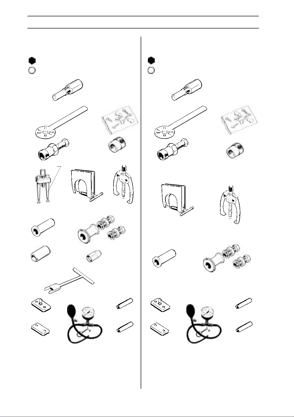
TOOLS
Tools for saws 42, 242 and 246 Tools for saws 254, 257 and 262
3 mm; 4 mm
8 mm
*compl 502 51 49-02
502 50 26-01*
502 70 03-01
502 50 33-01
502 51 49-01*
*502 51 54-01
502 50 99-01
3 mm; 4 mm
8 mm
502 50 33-01
*compl 502 51
49-02
502 51 49-01*
*502 51 54-01
502 50 26-01*
502 50 99-01
compl 502 50 31-01
502 50 82-01
502 51 32-01
502 50 72-01
502 50 71-01
502 51 61-01
502 50 30-07
502 51 50-01
502 51 00-02
compl 502 50 38-01
504 90 90-01
502 50 45-01
502 50 46-01
502 51 61-01
502 50 79-01
502 50 72-01
502 50 71-01
504 90 90-01
502 50 30-10
compl 502 50 38-01
502 50 45-01
502 50 46-01
16 – English
www.mymowerparts.com
Page 17
For Husqvarna Parts Call 606-678-9623 or 606-561-4983
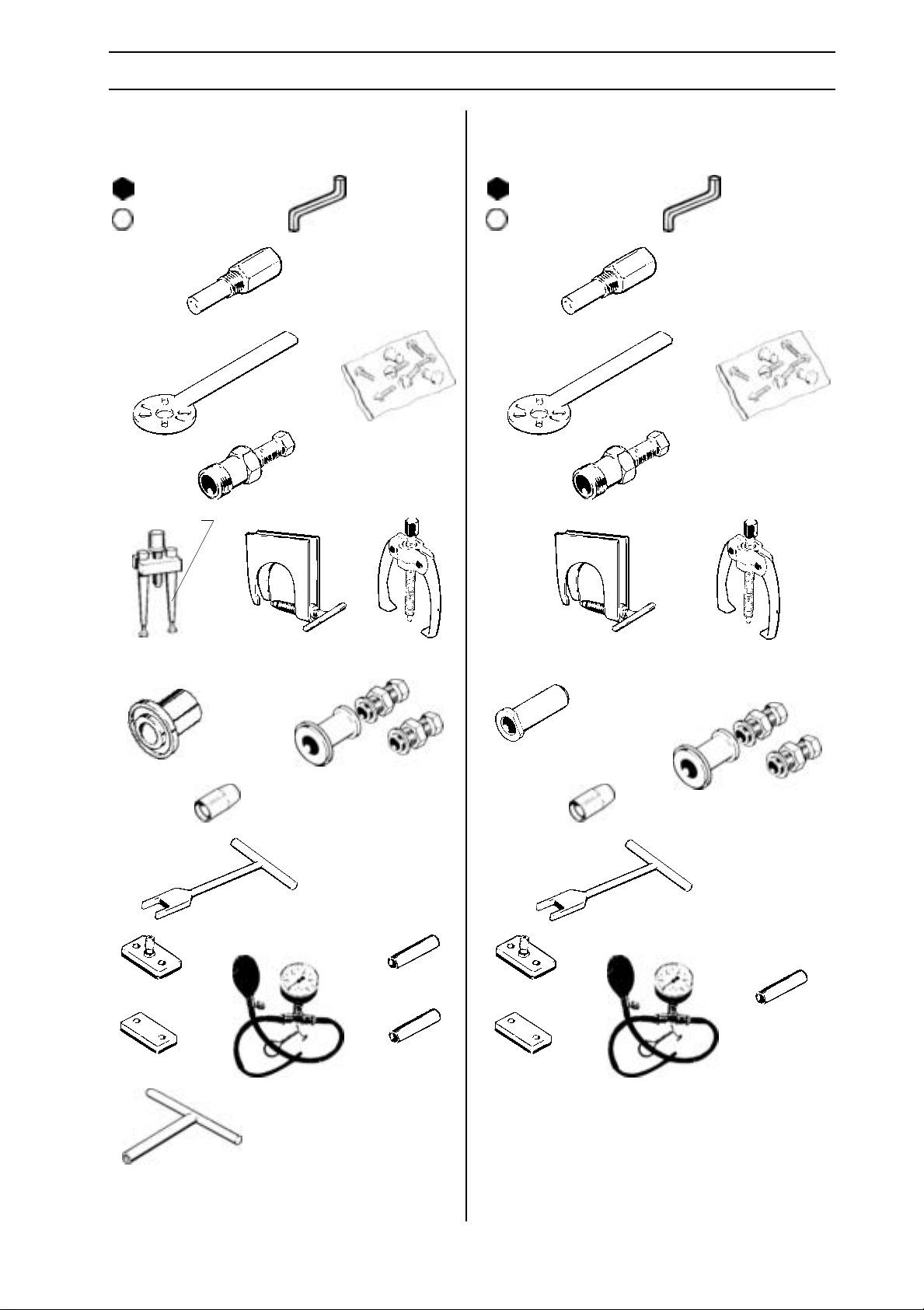
TOOLS
Tools for saws 61, 268 and 272
3 mm; 4 mm; 3/16"
8 mm
502 50 33-01
*compl 502 51 49-02 *compl 502 51 49-02
502 51 49-01*
502 50 26-01*
502 70 03-01
502 71 36-01 (4 mm)
*502 51 54-01
Tools for saws 281 and 288
3 mm; 4 mm; 3/16"
8 mm
502 51 49-01*
502 71 36-01 (4 mm)
502 50 33-01
*502 51 54-01
502 50 26-01*
compl 502 50 31-01
502 51 69-01
(268)
502 50 47-01
502 50 48-01
502 51 61-01
502 50 53-01 502 50 52-01
502 50 66-02
502 50 67-01
502 51 00-02
compl 502 50 38-01
504 90 90-01
502 50 30-04
502 50 45-01
502 50 46-01
502 51 61-01
502 50 82-01
502 50 66-02
compl 502 50 38-01
502 50 47-01
502 50 81-01
504 90 90-01
502 50 30-08
502 50 46-01
502 50 20-01
English – 17
www.mymowerparts.com
Page 18

For Husqvarna Parts Call 606-678-9623 or 606-561-4983
TOOLS
Tools for saws 394 and 3120
3 mm; 4 mm; 5 mm; 3/16"
8 mm; 10 mm
502 50 33-01
*compl 502 51 49-02
502 51 49-01*
*502 51 54-01
502 50 82-01
502 50 52-01
502 50 26-01*
504 90 90-01
502 50 30-08
502 50 66-02
compl 502 50 38-01
502 52 01-01 (394)
502 71 38-01 (3120)
502 71 39-01 (394)
18 – English
502 52 04-01
(394)
502 71 40-01
(3120)
www.mymowerparts.com
Page 19

For Husqvarna Parts Call 606-678-9623 or 606-561-4983
TOOLS
List of tools
Order number Designation
502 50 06-01 Pliers
502 50 16-01 Allen key
502 50 18-01 Allen key
502 50 19-01 Allen key
502 50 20-01 Assembly tool
502 50 22-01 Socket
502 50 23-01 Socket
502 50 26-01 Puller
502 50 30-04 Assembly tool
502 50 30-08 Assembly tool
502 50 30-09 Assembly tool
502 50 30-10 Assembly tool
502 50 31-01 Puller
502 50 33-01 Piston stop
502 50 37-01 Vacuum gauge
502 50 38-01 Pressure gauge
502 50 45-01 Extended socket
502 50 46-01 Extended socket
502 50 47-01 Cover plate
502 50 48-01 Cover plate
Order number Designation
502 51 49-01 Puller
502 51 49-02 Puller
502 51 50-01 Socket
502 51 54-01 Bolt set
502 51 61-01 Dismantling tool, crankcase
502 51 69-01 Assembly mandrel
502 51 69-01 Feeler gauges
502 51 94-01 Assembly mandrel
502 52 01-01 Cover plate
502 52 04-01 Spacer
502 54 03-01 Spacer
502 70 09-01 Pump blower
502 71 13-01 Test spark plug
502 71 14-01 Tachometer
502 71 36-01 Allen key
502 71 38-01 Cover plate
502 71 39-01 Cover plate
502 71 40-01 Spacer
504 90 29-02 Cover plate
504 90 90-01 Puller
502 50 52-01 Assembly socket
502 50 57-01 Allen key
502 50 64-01 Allen key
502 50 66-02 U-key
502 50 67-01 U-key
502 50 70-01 Assembly tool, piston
502 50 71-01 Cover plate
502 50 72-01 Cover plate
502 50 79-01 Assembly mandrel
502 50 81-01 Cover plate
502 50 82-01 Assembly mandrel
502 50 83-01 Hook, tank valve
502 50 86-01 Allen key
502 50 87-01 Allen key
502 50 88-01 Allen key
502 50 99-01 Puller sleeve
502 51 00-02 U-key
502 51 02-01 Assembly fixture
502 51 32-01 Assembly sleeve
502 51 34-02 Feeler gauge
504 98 26-01 Silicone rubber
505 26 79-12 Assembly mandrel
505 38 18-17 Puller
www.mymowerparts.com
English – 19
Page 20

For Husqvarna Parts Call 606-678-9623 or 606-561-4983
SERVICE DATA
Saws 36 and 41
●
5
15
10
●
▲
4
●
■
6
▲
●
Character key
Numbers by components that are bolted
refer to the tightening torque in Nm.
▲ = Lubricate using two-stroke oil.
■ = Lubricate using saw chain oil.
● = Lubricate using grease.
= Locking fluid (Loctite).
20 – English
www.mymowerparts.com
Page 21
For Husqvarna Parts Call 606-678-9623 or 606-561-4983
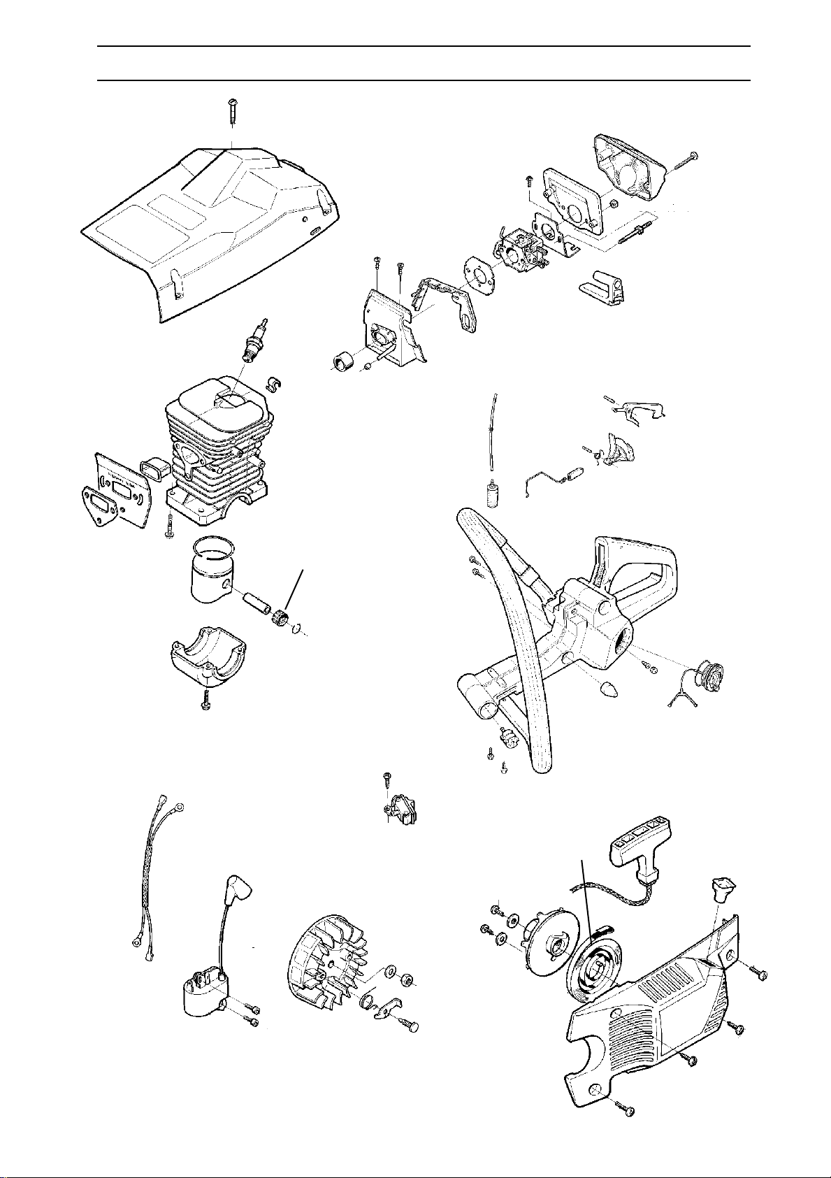
SERVICE DATA
6
15
▲
4
4
●
4
28
3
www.mymowerparts.com
English – 21
Page 22

For Husqvarna Parts Call 606-678-9623 or 606-561-4983
SERVICE DATA
●
5
Saws 42, 242 and 246
8-10
7-8
242
4-5
15
42 246
42 246
242
●
10
4
8
5
●
▲
▲
■
Character key
Numbers by components that are bolted
refer to the tightening torque in Nm.
▲ = Lubricate using two-stroke oil.
■ = Lubricate using saw chain oil.
● = Lubricate using grease.
= Locking fluid (Loctite).
22 – English
www.mymowerparts.com
3
●
●
Page 23

For Husqvarna Parts Call 606-678-9623 or 606-561-4983
SERVICE DATA
2
3
13
9
2
20
▲
▲
2
●
2
4
4
28
6
9
2
English – 23
www.mymowerparts.com
Page 24

For Husqvarna Parts Call 606-678-9623 or 606-561-4983
SERVICE DATA
3-4
●
2-3
25-35
Saws 40 and 45
7-8
●
■
●
2-3
▲
▲
●
2-3
Character key
Numbers by components that are bolted
refer to the tightening torque in Nm.
▲ = Lubricate using two-stroke oil.
■ = Lubricate using saw chain oil.
● = Lubricate using grease.
= Locking fluid (Loctite).
24 – English
www.mymowerparts.com
2-3
10-12
Page 25

For Husqvarna Parts Call 606-678-9623 or 606-561-4983
SERVICE DATA
20
2-3
3-4
2-3
2-3
2-3
▲
3-4
25-30
2-3
8-10
2-3
2-3
2-3
●
2-3
www.mymowerparts.com
English – 25
Page 26

For Husqvarna Parts Call 606-678-9623 or 606-561-4983
SERVICE DATA
4-5
●
Saws 51 and 55
7-8
15
30-40
6-8
■
▲
▲
●
3-4
3-4
●
8-10
1,5-2
Character key
Numbers by components that are bolted
refer to the tightening torque in Nm.
▲ = Lubricate using two-stroke oil.
■ = Lubricate using saw chain oil.
● = Lubricate using grease.
= Locking fluid (Loctite).
26 – English
www.mymowerparts.com
3-4
●
●
Page 27

For Husqvarna Parts Call 606-678-9623 or 606-561-4983
SERVICE DATA
3-4
3-4
3-4
15
8-10
12-14
▲
25
1-2
3-5
●
3-4
www.mymowerparts.com
3-4
English – 27
Page 28

For Husqvarna Parts Call 606-678-9623 or 606-561-4983
SERVICE DATA
5
15
●
Saws 254 and 257
254
10
5
257
5
10
35
●
Character key
Numbers by components that are bolted
refer to the tightening torque in Nm.
▲ = Lubricate using two-stroke oil.
■ = Lubricate using saw chain oil.
● = Lubricate using grease.
= Locking fluid (Loctite).
4
■
8
●
3
▲
▲
●
●
5
3
28 – English
www.mymowerparts.com
Page 29
For Husqvarna Parts Call 606-678-9623 or 606-561-4983
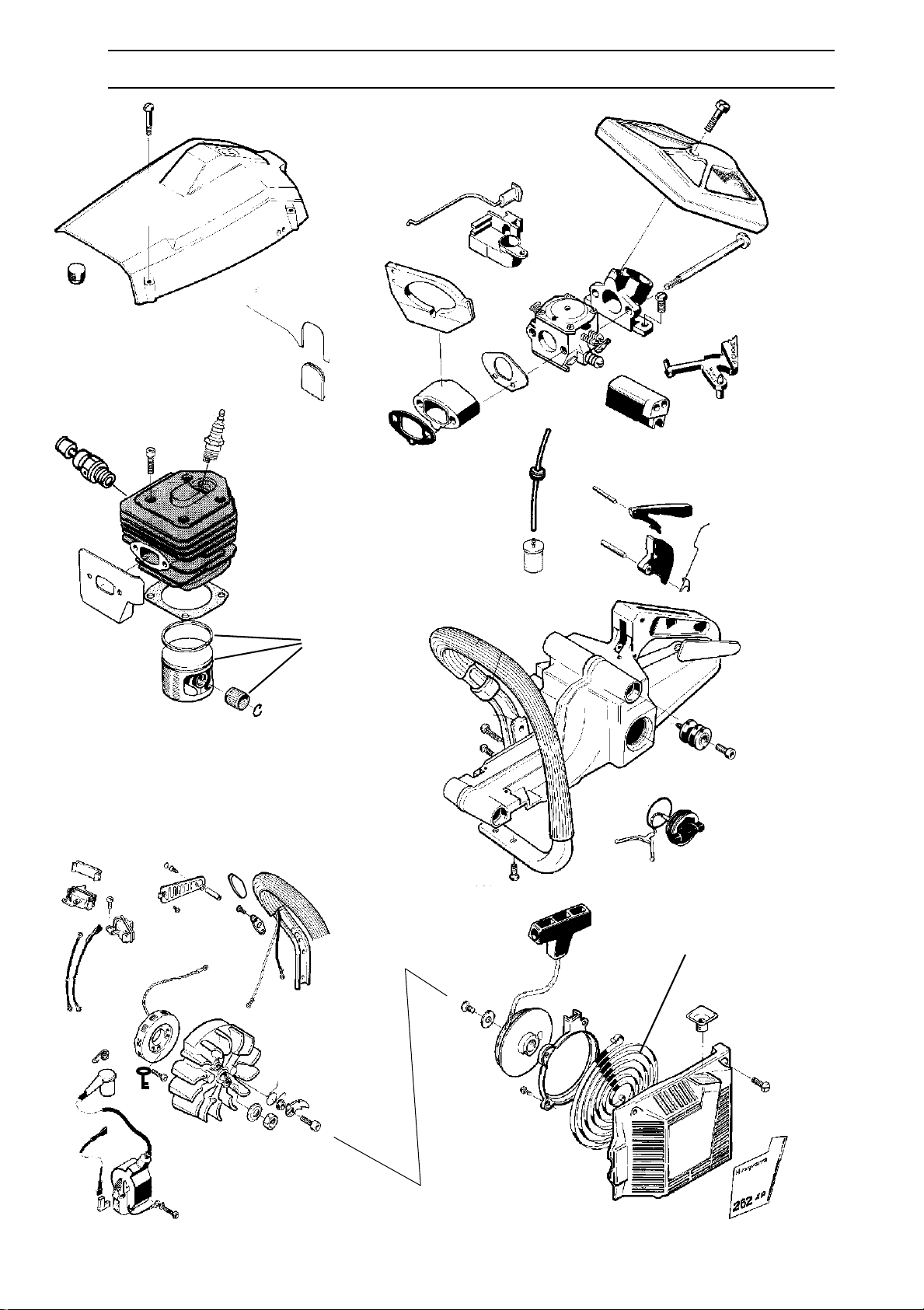
SERVICE DATA
3
4
13
10
20
▲
5
254
4
4
●
2
3
9
28
5
English – 29
www.mymowerparts.com
Page 30

For Husqvarna Parts Call 606-678-9623 or 606-561-4983
SERVICE DATA
15
●
5
Saw 262
4
6
10
35
●
Character key
Numbers by components that are bolted
refer to the tightening torque in Nm.
▲ = Lubricate using two-stroke oil.
■ = Lubricate using saw chain oil.
● = Lubricate using grease.
= Locking fluid (Loctite).
4
■
8
●
4
▲
▲
●
●
4
3
30 – English
www.mymowerparts.com
Page 31
For Husqvarna Parts Call 606-678-9623 or 606-561-4983
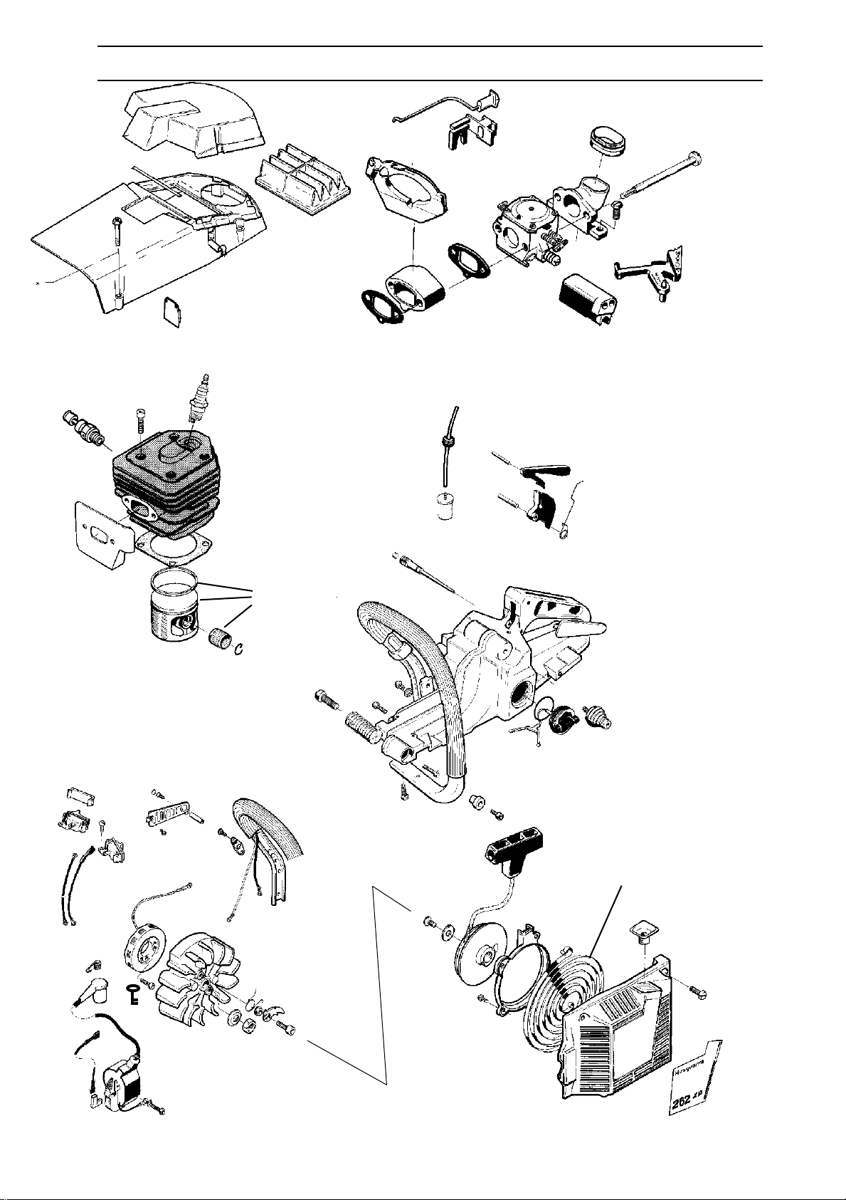
SERVICE DATA
2
4
13
9
20
▲
5
5
4
4
●
2
3
4
9
28
5
English – 31
www.mymowerparts.com
Page 32
For Husqvarna Parts Call 606-678-9623 or 606-561-4983
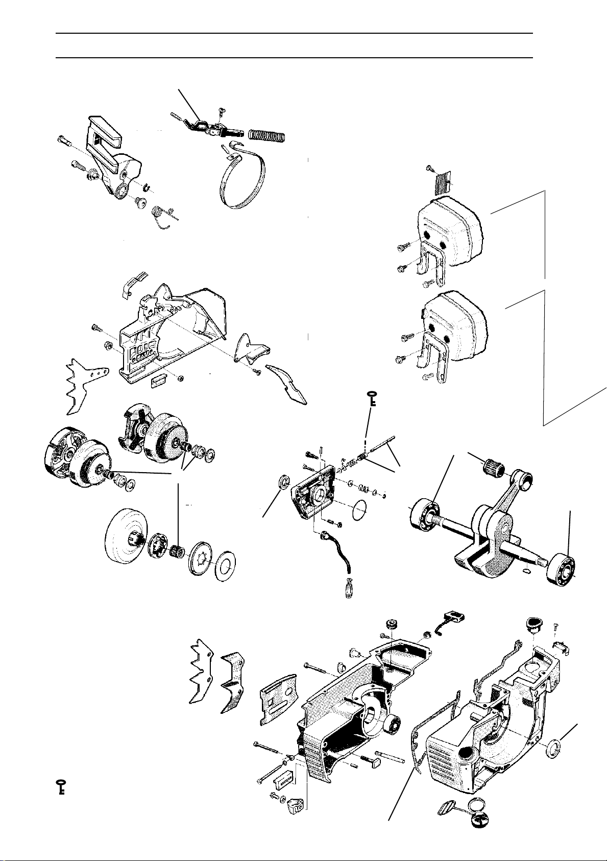
SERVICE DATA
●
5
15
Saws 61, 268 and 272
2
10
6
6
10
6
35
268 272
35
61
●
5
■
●
4
8
▲
▲
1
Character key
Numbers by components that are
bolted refer to the tightening torque in Nm.
▲ = Lubricate using two-stroke oil.
■ = Lubricate using saw chain oil.
● = Lubricate using grease.
= Locking fluid (Loctite).
32 – English
www.mymowerparts.com
●
3
●
Page 33
For Husqvarna Parts Call 606-678-9623 or 606-561-4983
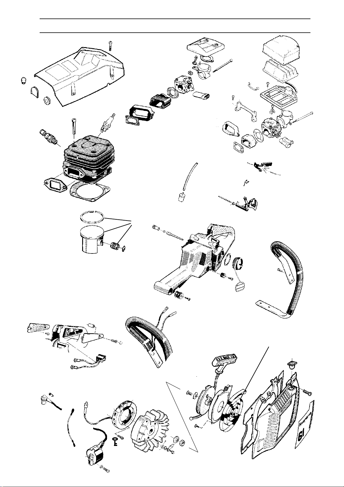
SERVICE DATA
3
1
3
61
1
3
1
15
10
268 272
14
3
272
▲
5
4
6
6
4
●
4
3
3
28
9
4
www.mymowerparts.com
English – 33
Page 34
For Husqvarna Parts Call 606-678-9623 or 606-561-4983
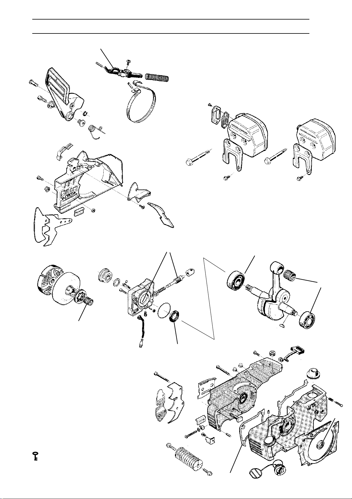
SERVICE DATA
5
15
●
4
Saws 281 and 288
13
6
35
5
●
Character key
Numbers by components that are bolted
refer to the tightening torque in Nm.
▲ = Lubricate using two-stroke oil.
■ = Lubricate using saw chain oil.
● = Lubricate using grease.
= Locking fluid (Loctite).
■
●
8
6
▲
▲
●
34 – English
●
www.mymowerparts.com
Page 35
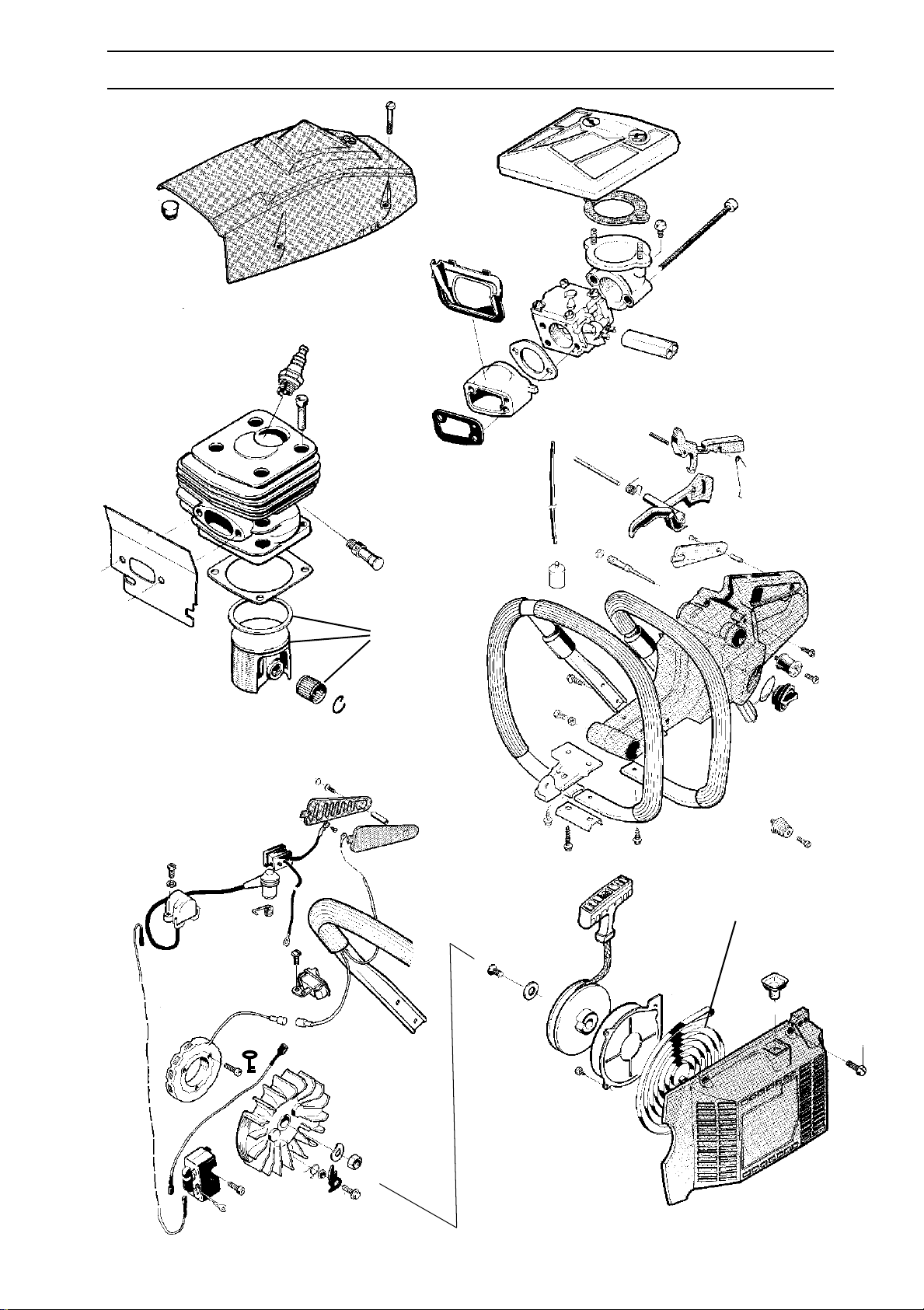
For Husqvarna Parts Call 606-678-9623 or 606-561-4983
SERVICE DATA
4
3
6
20
11
17
▲
7
7
1
3
4
7
6
●
3
35
7
9
English – 35
4
www.mymowerparts.com
Page 36
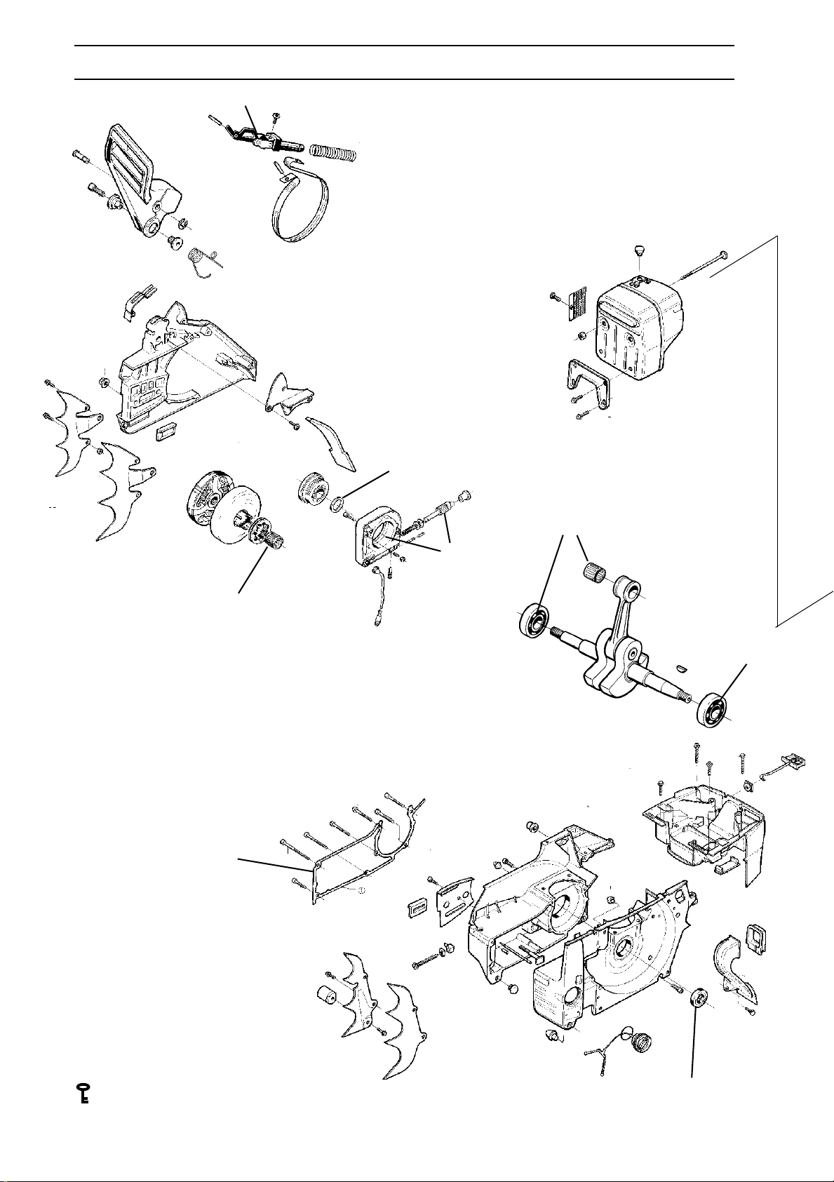
For Husqvarna Parts Call 606-678-9623 or 606-561-4983
SERVICE DATA
●
Saw 394
5
10-12
15
6-8
●
2-4
■
●
7-9
●
▲
▲
Character key
Numbers by components that are
bolted refer to the tightening torque
in Nm.
▲ = Lubricate using two-stroke oil.
■ = Lubricate using saw chain oil.
● = Lubricate using grease.
= Locking fluid (Loctite).
36 – English
www.mymowerparts.com
●
Page 37
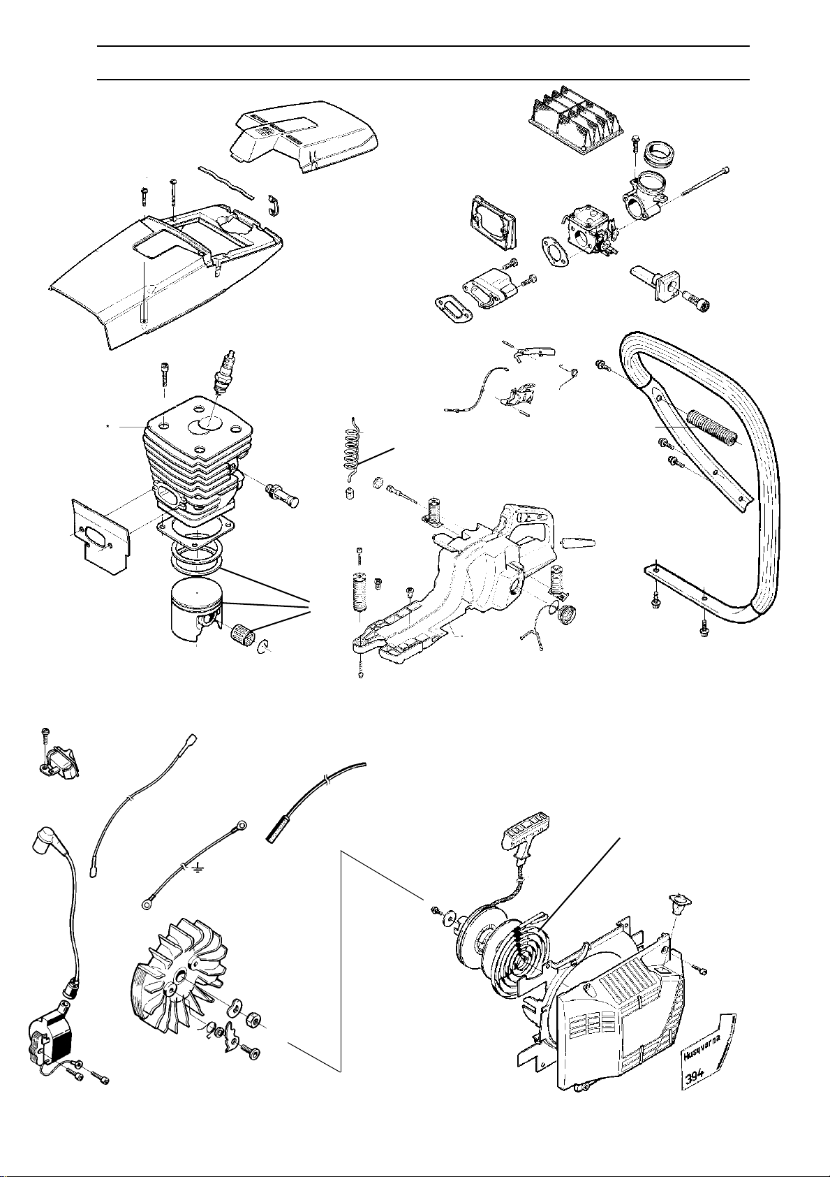
For Husqvarna Parts Call 606-678-9623 or 606-561-4983
SERVICE DATA
5-6
10-12
20-22,5
12-14
▲
3-5
6
▲
3-5
5-6
2-3
●
4-5
30-40
English – 37
www.mymowerparts.com
Page 38
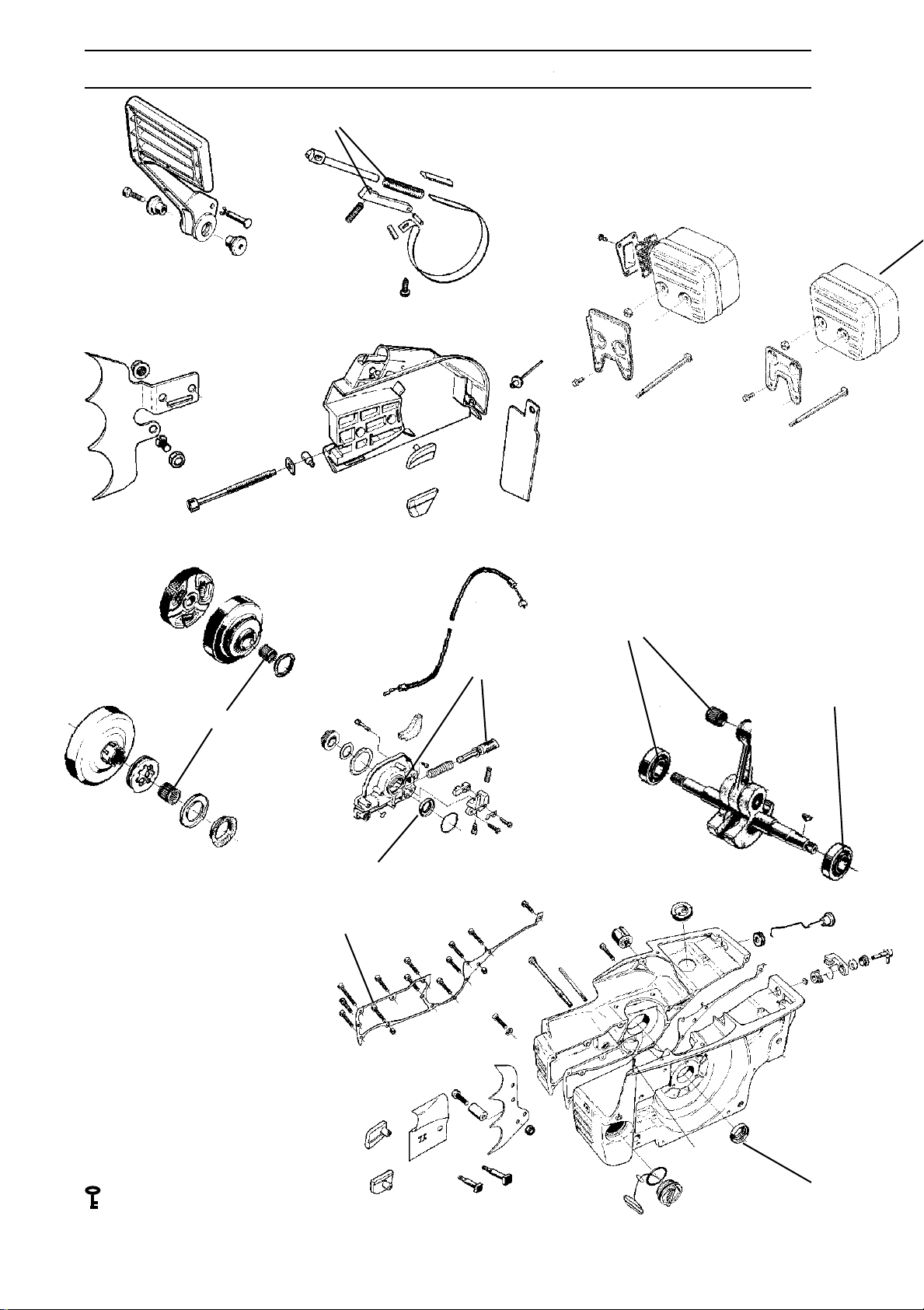
For Husqvarna Parts Call 606-678-9623 or 606-561-4983
SERVICE DATA
●
5
15
5
38
Saw 3120
4
12
●
5
●
Character key
Numbers by components that are bolted
refer to the tightening torque in Nm.
▲ = Lubricate using two-stroke oil.
■ = Lubricate using saw chain oil.
● = Lubricate using grease.
= Locking fluid (Loctite).
▲
■
▲
3
1
●
8
7
5
5
7
8
●
38 – English
www.mymowerparts.com
Page 39
For Husqvarna Parts Call 606-678-9623 or 606-561-4983
SERVICE DATA
3
5
7
17
12
20
▲
▲
5
6
3
5
10
12
8
●
40
4
9
4
4
English – 39
www.mymowerparts.com
Page 40

For Husqvarna Parts Call 606-678-9623 or 606-561-4983
TROUBLE SHOOTING
Trouble shooting schematic
Faults that can develop on the chain saw are
divided into four groups as follows. In each category, possible malfunctions are shown on the left,
with a list of possible faults on the right. The most
probable fault is given first and so on.
Starting
Difficult starting
Carburettor
leaking fuel
Flooding when
the engine is not
running
Adjust L-screw
Air filter blocked
Choke not working correctly
Worn choke shaft
Worn choke plate
Fuel filter blocked
Fuel line blocked
Piston ring seized
Blocked impulse channel
Loose or faulty fuel pipe
Hole in diaphragm
Worn needle valve/needle
Control system sticking
Control system set too high
Leak in control system (air or
fuel)
Loose cover on carburettor
pump side
Worn needle valve
Control system set too high
Control system sticking
Idling (low rpm) (cont.)
Idles when L-screw
closed
Idling uneven
Worn needle valve/needle
Leaking control diaphragm/
cover plate
Control system sticking
Worn throttle lever
Faulty diffuser jet
Fuel filter blocked
Fuel line blocked
Leaking manifold
Loose carburettor mounting
Worn throttle valve shaft
Loose throttle valve screw
Worn throttle valve
Control system sticking
Leak in throttle system (air or
fuel)
Control diaphragm centre knob
is worn
Hole in diaphragm
Leaking control diaphragm/
cover plate
Crankcase leaking
Idling (low rpm)
Will not idle
Idling too rich
Adjust L-screw
Leaking manifold (intermediate)
Loose carburettor mounting
Loose or faulty fuel pipe
Fuel filter blocked
Fuel line blocked
Fuel tank breather blocked
Throttle shaft and lever stiff
Throttle cable sticking
Defective throttle return spring
Bent throttle lever shaft stop
Faulty diffuser jet
Adjust L-screw
Worn needle valve/needle
Control system set too high
Worn throttle lever
Leaking control diaphragm/
cover plate
Control system sticking
L-screw requires
constant adjustment
Too much fuel at idling
Fuel line blocked
Control system set too high
Control system sticking
Control system (air or fuel)
Leaking control diaphragm/
cover plate
Faulty diffuser jet
Crankcase leaking
Control system set too high
Control system sticking
Control system damaged
Worn needle valve
Leaking control diaphragm/
cover plate
Control system incorrectly
assembled
40 – English
www.mymowerparts.com
Page 41

For Husqvarna Parts Call 606-678-9623 or 606-561-4983
TROUBLE SHOOTING
High rpm
Will not run at full
throttle
Low power
Will not
”four-stroke”
Adjust H-screw
Blocked air filter
Blocked fuel tankbreather
Blocked fuel filter
Fuel line blocked
Loose or damaged fuel line
Impulse channel leaking
Impulse channel blocked
Loose cover on carburettor
pump side
Faulty pump diaphragm
Leaking manifold
Loose carburettor mounting
Control system set too low
Control system damaged
Control system incorrectly
assembled
Leaking control diaphragm/cover
Control system sticking
Blocked silencer
Adjust H-screw
Blocked fuel tankbreather
Blocked fuel filter
Impulse channel leaking
Impulse channel blocked
Loose cover on carburettor
pump side
Faulty pump diaphragm
Blocked air filter
Control system sticking
Leak in throttle system (air or
fuel)
Control system incorrectly
assembled
Loose diaphragm
Hole in diaphragm
Leaking control diaphragm/cover
Blocked fuel tank breather
Blocked fuel filter
Fuel line blocked
Loose or damaged fuel line
Impulse channel leaking
Impulse channel blocked
Loose cover on carburettor
pump side
Faulty pump diaphragm
Leaking manifold
Loose carburettor mounting
bolts
Control system set too low
Leak in throttle system (air or
fuel)
Control system incorrectly
assembled
Loose diaphragm
Hole in diaphragm
Leaking control diaphragm/cover
Acceleration and retardation
Does not accelerate
Motor stalls when
throttle released
Over rich acceleration
Adjust L-screw
Adjust H-screw
Blocked air filter
Blocked fuel tankbreather
Blocked fuel filter
Fuel line blocked
Loose or damaged fuel line
Impulse channel blocked
Loose cover on carburettor
pump side
Faulty pump diaphragm
Leaking manifold
Loose carburettor mounting
Throttle set too low
Control system incorrectly
assembled
Control system sticking
Faulty diffuser jet
Blocked silencer
Adjust L-screw
Adjust H-screw
Faulty pump diaphragm
Control system set too high
Control system sticking
Faulty diffuser jet
Adjust L-screw
Adjust H-screw
Blocked air filter
Faulty pump diaphragm
Faulty diffuser jet
Trouble shooting methods
In addition to faults given in the above schematic,
trouble shooting can be carried out on a specific
component or sub-system of the chain saw. The
different testing procedures are described in
respective sections and are as follows:
1. Pressure testing the carburettor.
See page 100.
2. Pressure testing the crankcase and cylinder.
See page 114.
3. Pressure testing the decompression valve.
See page 114.
4. Checking the operation of the chain brake.
See page 47.
www.mymowerparts.com
English – 41
Page 42
For Husqvarna Parts Call 606-678-9623 or 606-561-4983
SAFETY EQUIPMENT
Chain brake
A
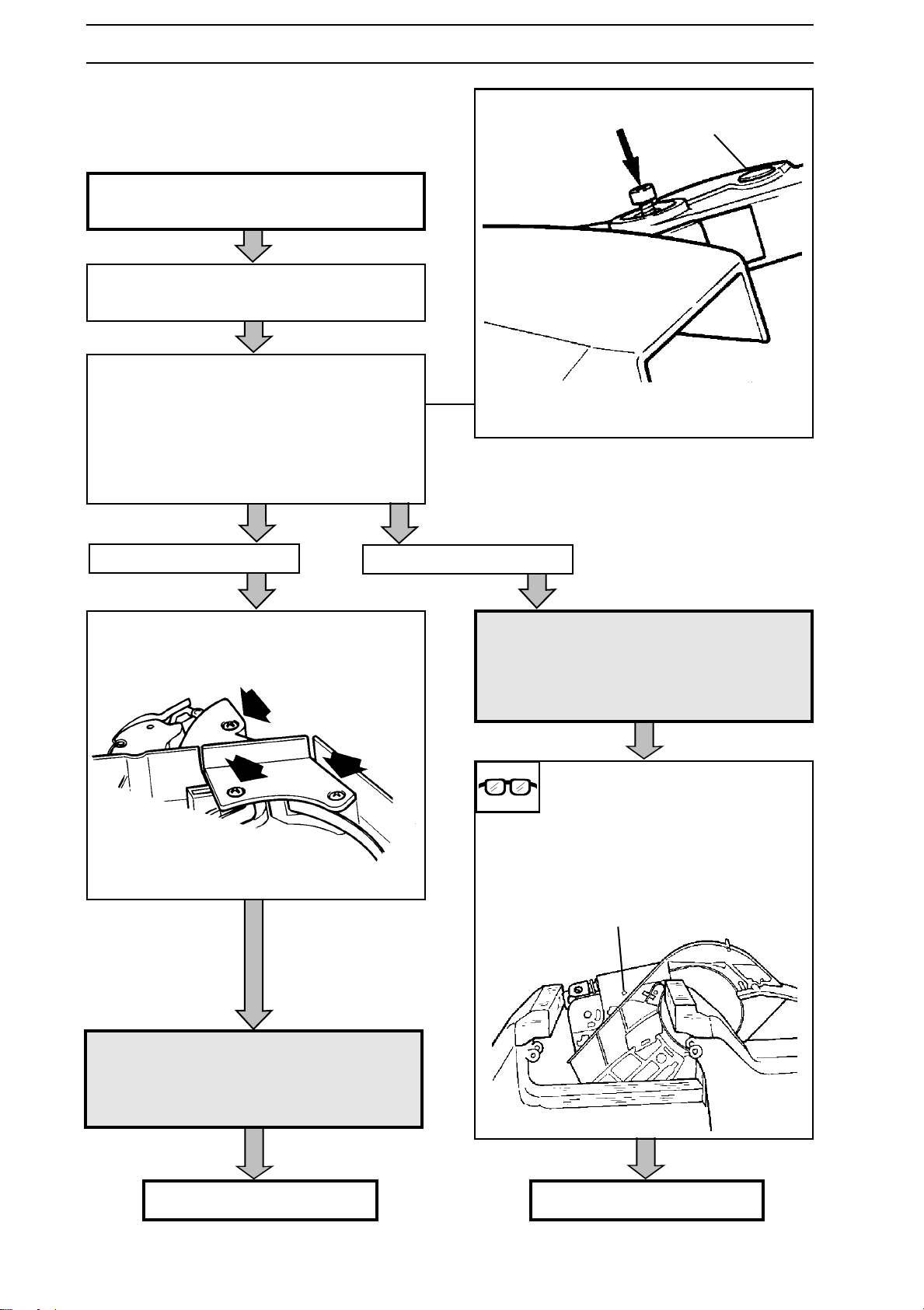
Dismantling
Dismantle the clutch cover and clean. See
the operating instructions.
Slide the hand guard forwards so that the
brake is actuated.
Loosen the screw on the hand guard and
screw back 2 turns.
Gently hit the screw so that the threaded part
of the bushing can be removed.
Dismantle the other part of the bushing by
means of a punch.
Remove the cylindrical pin A.
All saws except 3120
Remove the cover on the chain brake spring.
The cover has 4 or 5 screws.
3120
WARNING!
!
Place the clutch cover in a vice with the jaws
positioned as shown below and release the
tubular pin B.
Carefully knock out the tubular pin B.
If the clutch cover slides out of
the vice's grip the spring can fly
out with immense force resulting
in personal injury!
Wear protective glasses!
B
!
42 – English
WARNING!
If the brake is not 'on', the spring
can fly out resulting in personal
injury.
Wear protective glasses!
Continues on next page.
www.mymowerparts.com
3120 continues on next page.
Page 43
For Husqvarna Parts Call 606-678-9623 or 606-561-4983
SAFETY EQUIPMENT
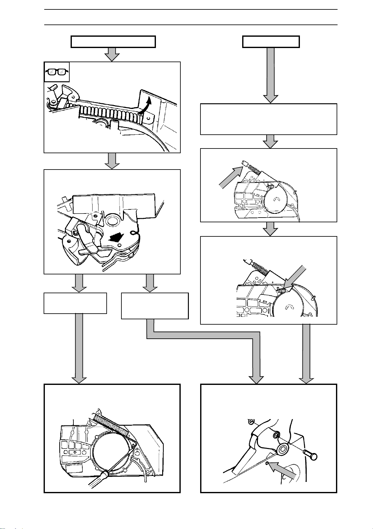
All saws except 3120
Slide up the back edge of the
spring with a screwdriver.
Use a punch to knock out the pin holding the
knee link.
3120
Carefully unscrew the vice so that the pressure rod and the ratchet move out of the
clutch cover.
Dismantle the pressure rod from the brake
band.
36, 41, 61, 268,
272, 281 and 288
Lift up the band's fixed end using a screwdriver and remove the loose parts.
40, 42, 45, 51,
242, 246, 55, 254,
257, 262 and 394
Remove the screw that holds the fixed end of
the band.
Knock out the band's fixed end using a
punch through the hole in the clutch cover
and remove the loose parts.
www.mymowerparts.com
English – 43
Page 44
For Husqvarna Parts Call 606-678-9623 or 606-561-4983
SAFETY EQUIPMENT
Cleaning and Inspection
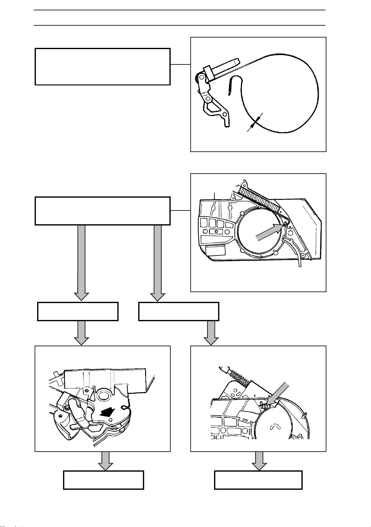
Clean and inspect all parts.
The thickness of the brake band must not be
under 0.8 mm at any point.
Min. 0.8 mm
Assembly
Fit the band's fixed end into position on the
clutch cover.
All saws except 3120
Grease the knee link and knock in the tubular
pin that holds the knee link.
3120
Fit the screw that holds the band's fixed end.
44 – English
Continues on next page.
www.mymowerparts.com
3120 continues on next page.
Page 45
For Husqvarna Parts Call 606-678-9623 or 606-561-4983
SAFETY EQUIPMENT
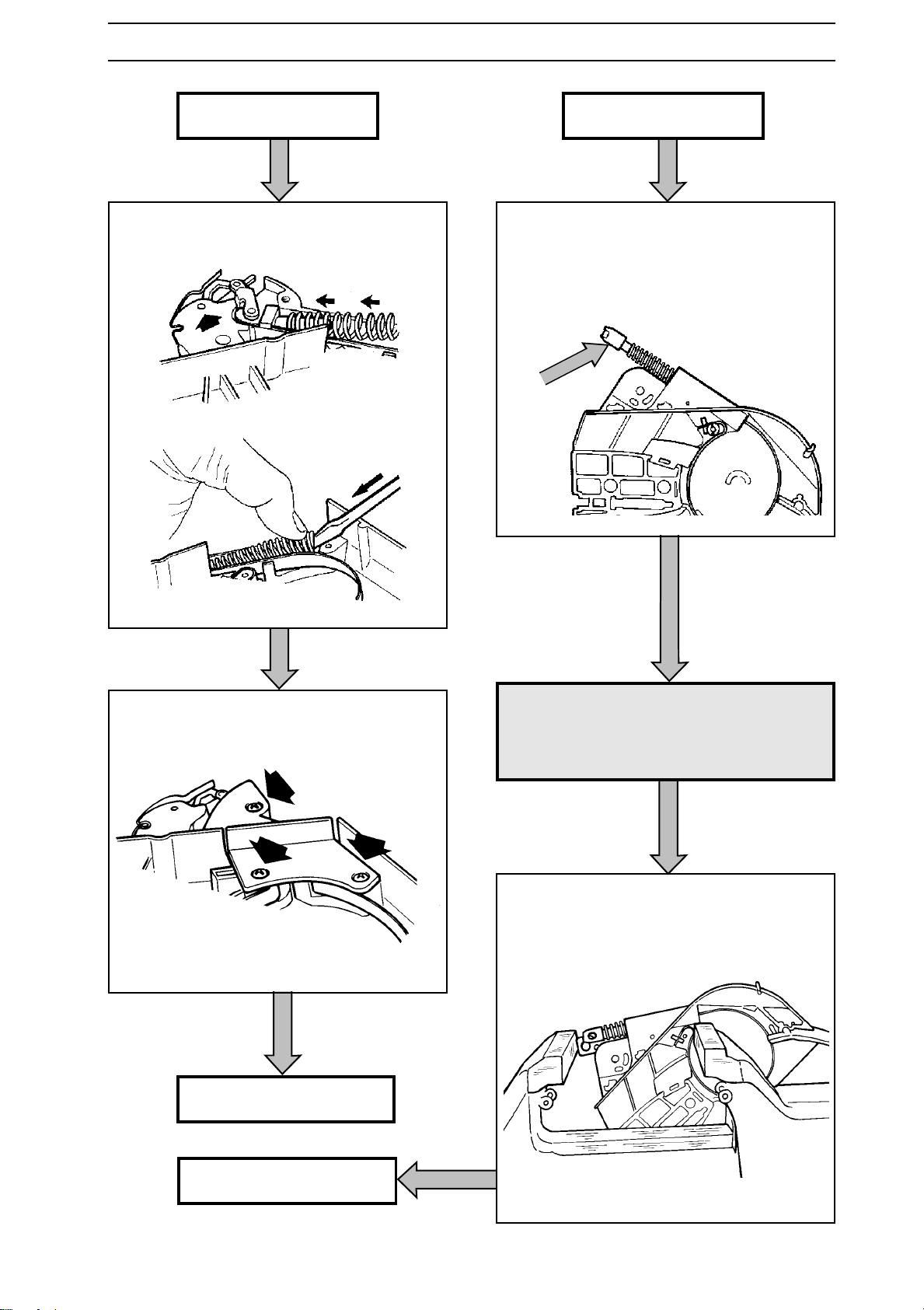
All saws except 3120
Slide the spring over the knee link's stud and
press down the opposite end of the spring into
its recess.
3120
Fit the spring and screw onto the pressure
rod on the brake band.
Note! Plastic sleeve.
Bottom the screw onto the pressure rod
thread and back off 4-5 turns.
Fit the cover over the spring.
Continues on next page.
WARNING!
!
Grease and fit the ratchet. Set the unit in a
vice, positioned in the jaws as shown below.
If the clutch cover slides out of
the vice's grip the spring can fly
out with immense force resulting
in personal injury!
3120 continues on next page.
www.mymowerparts.com
English – 45
Page 46
For Husqvarna Parts Call 606-678-9623 or 606-561-4983
SAFETY EQUIPMENT
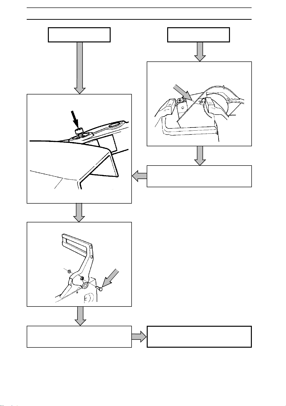
All saws except 3120
Fit the hand guard, the two bushings and the
screw.
3120
Carefully tighten the vice until the hole for the
tubular pin and the ratchet align.
Fit the cylindrical pin.
Carefully knock in the pin.
Pull back the hand guard so that the brake is
not actuated.
46 – English
www.mymowerparts.com
Check the chain brake as described on the
next page.
Page 47
For Husqvarna Parts Call 606-678-9623 or 606-561-4983
SAFETY EQUIPMENT
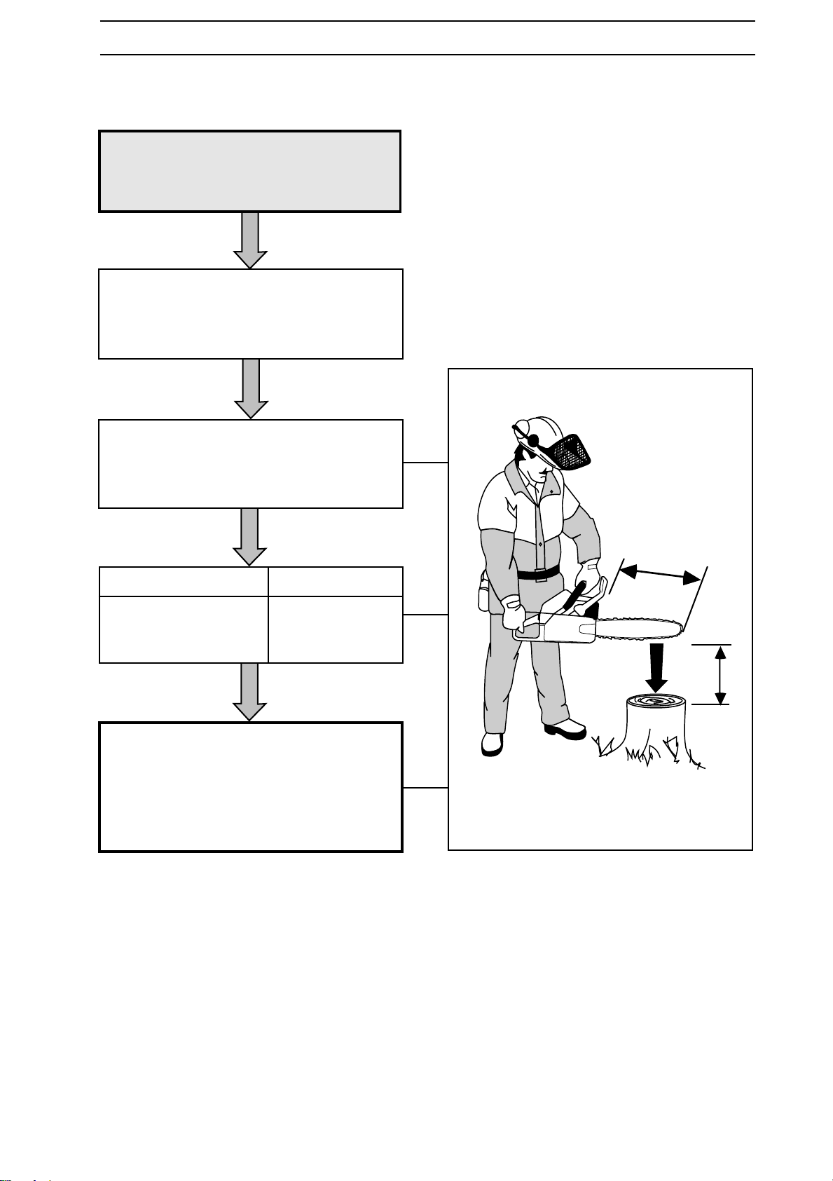
Checking brake operation
WARNING!
!
The engine should not be running
during the test.
Test that the chain brake comes on as
follows:
After repair, the chain brake
must be checked as set out in
the following instructions.
Hold the chain saw above a firm surface.
The distance between the bar and the
surface are shown in the table below.
Bar length, L Height, H
15-20 inches 50 cm
21-28 inches 70 cm
29-32 inches 80 cm
Release the front handle and let the chain
saw rotate around the rear handle.
When the bar nose hits the surface the
chain brake should trip.
L
H
www.mymowerparts.com
English – 47
Page 48
For Husqvarna Parts Call 606-678-9623 or 606-561-4983
SAFETY EQUIPMENT
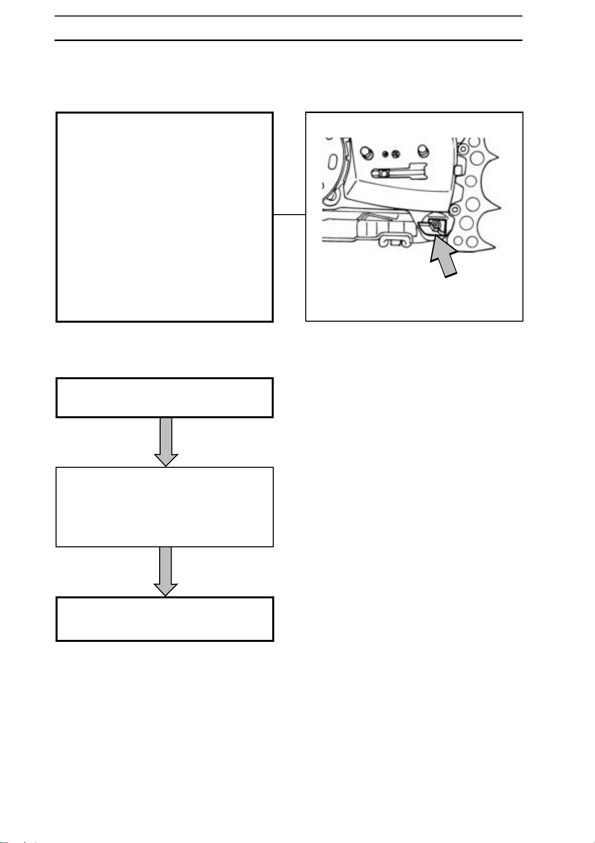
Chain catcher
Description
The chain catcher is intented to catch the
chain if it should break.
The chain catcher has a different design and
is secured differently on the chain saws
described in this manual.
The following designs are used:
• Aluminium angle.
• Plastic angle.
• Fixed roller.
• Rotating roller.
The following securing methods are used:
• Using screws on the crankcase.
• Using screws on the spike.
• Using nuts on the spike.
Replacing
Dismantle the chain and bar. See the operating instructions
Check the chain catcher and replace if broken or badly damaged.
The tightening torque is stated in the service
data
Reassemble the chain and bar. See the
operating instructions
48 – English
www.mymowerparts.com
Page 49
For Husqvarna Parts Call 606-678-9623 or 606-561-4983
SAFETY EQUIPMENT
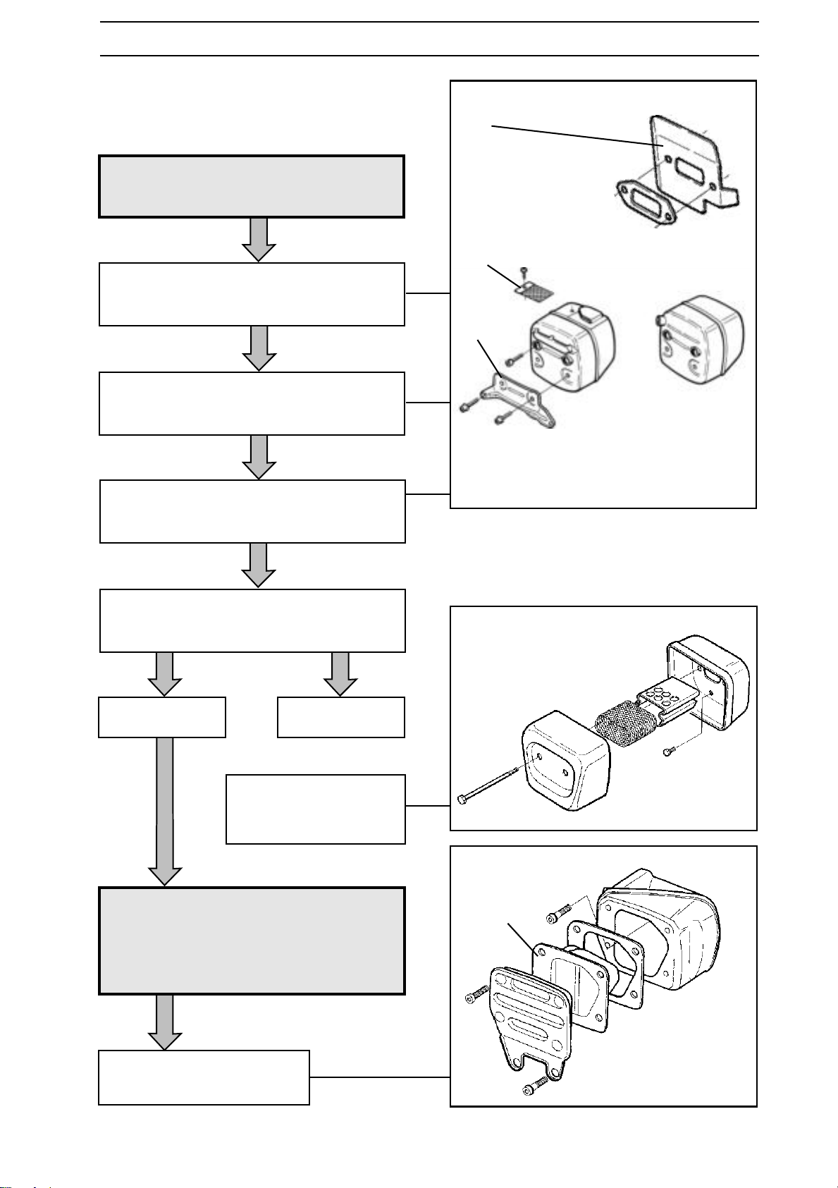
Muffler
Dismantling
WARNING!
!
If the saw is equipped with muffler mounting
(A), unscrew this from the crankcase and
muffler.
Unscrew the muffler from the cylinder
(M5 or M6 bolts, M5 or M6 nuts).
Remove the muffler, gasket and cooling plate
(B) if the saw is so equipped.
Do not touch the muffler until it
has cooled. Risk of burns!
B
C
A
If the saw is equipped with a spark arrester
(C), remove this.
Saw 242 Cat
WARNING!
!
The coating on and in the catalytic
converter element (A) is hazardous
to your health if touched. Wear
protective gloves when working on
a catalytic converter
Dismantle the muffler
as shown in the figure
to the right.
Saws 36 and 41
1
A
Dismantle the muffler as shown
in the figure to the right.
www.mymowerparts.com
English – 49
Page 50
For Husqvarna Parts Call 606-678-9623 or 606-561-4983
SAFETY EQUIPMENT
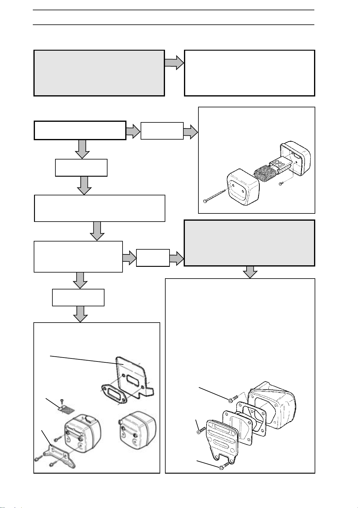
Cleaning and Inspection
WARNING!
!
The coating on and in the catalytic
converter element (A) is hazardous
to your health if touched. Wear
protective gloves when working on
a catalytic converter
Assembly
Clean all contact surfaces.
Other saws
If the saw is equipped with a spark arrester
(C), fit this.
Fit the cooling plate (B) if
fitted, gasket and muffler on
the cylinder.
Saws 36 and 41
242 Cat
Clean all parts and check the following:
• That the muffler and muffler mountings are
not cracked or otherwise damaged.
• That the gaskets are OK.
Assemble the muffler and fit to the
cylinder. Tightening torque, see page
20.
WARNING!
The coating on and in the cata-
!
lytic converter element (A) is
hazardous to your health if
touched. Wear protective gloves
when working on a catalytic
converter
Other saws
Tighten all bolts using the tightening
torque set out in the "Service data".
B
C
A
1
See "Service data" regarding tightening torques.
1. Secure the muffler on the cylinder using the two
2. Assemble the muffler components using the four
3. Secure the muffler to the crankcase using the two
Only specially treated bolts may be used on
the catalytic converter (high temperature).
See spare parts catalogue.
bolts (D).
bolts (E).
bolts (F) and Loctite.
D
E
F
50 – English
www.mymowerparts.com
Page 51
For Husqvarna Parts Call 606-678-9623 or 606-561-4983
SAFETY EQUIPMENT
Stop switch
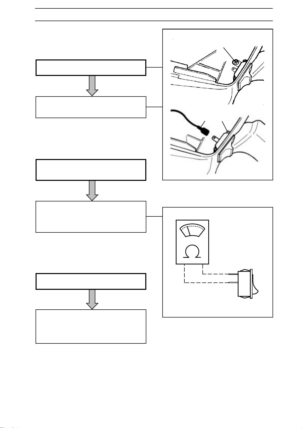
A
Dismantling
Remove the earth screw (A) and cable (B).
Press the switch's securing tabs (C) towards
each other and push out the switch.
BC
Cleaning and Inspection
Clean the switch and check its resistance as
follows:
Connect an ohm meter as shown in the fig.
The resistance should be:
In the stop position less than 0.1 ohm.
In the run position more than 1000 ohm.
Assembly
Press the switch into the socket on the tank unit.
Fit the earth screw (A) and cable (B).
Note! On some models the earth cable should
be connected to the earth screw.
www.mymowerparts.com
English – 51
Page 52
For Husqvarna Parts Call 606-678-9623 or 606-561-4983
SAFETY EQUIPMENT
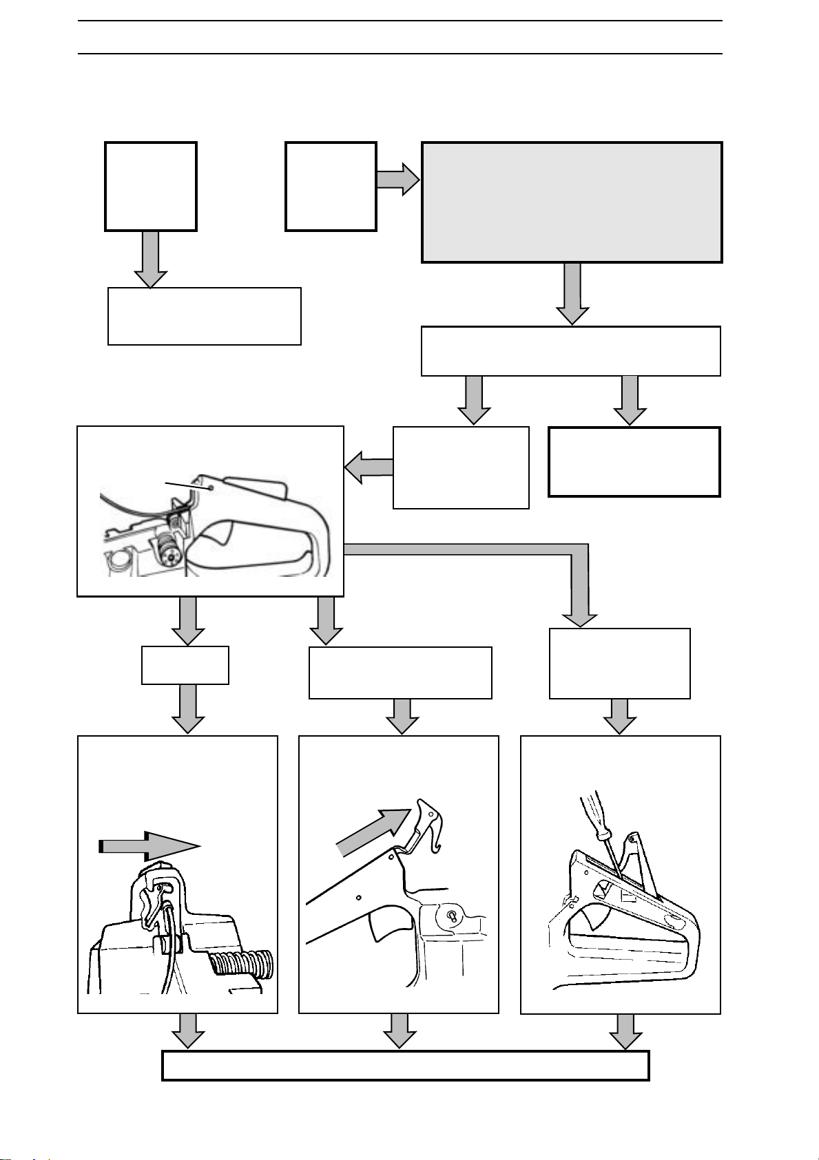
Throttle lock
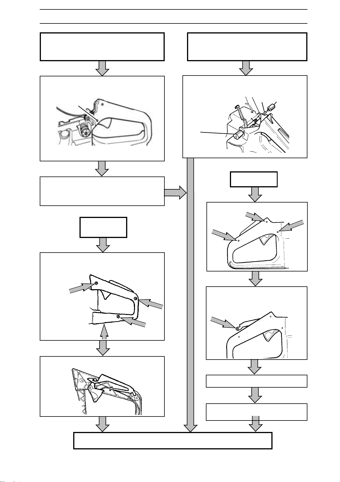
Dismantling
WARNING!
Saws 40, 45.
See continuation on next page.
Other saws.
!
Remove the tank unit from the engine
assembly. See page 103.
The fuel used in the chain saw
poses the following hazards:
1. The liquid and its vapours
are poisonous.
2. Can cause skin irritation.
3. Is highly inflammable.
Dismantle the throttle lock pin (A)
using a punch.
A
Saw 394
Turn the throttle lock as
shown in the figure, and lift
it out with the spring from
the cut-out in the handle.
Saws 61, 268, 268K,
272XP , 272K, 272S,
281XP, 288XP and
394.
Saws 61, 268, 272XP , 272K,
272S, 281XP and 288XP.
Slide the throttle lock and
remove it forwards as
shown in the figure.
Saw 3120.
See continuation on next
page.
Saws 36, 41, 42, 55,
242XP, 246, 51,
254XP, 257 and
262XP.
Carefully prise up the lock
from the slot and remove.
52 – English
Continues on next page.
www.mymowerparts.com
Page 53
For Husqvarna Parts Call 606-678-9623 or 606-561-4983
SAFETY EQUIPMENT
Saws 61, 268, 268K, 272XP , 272K, 272S,
281XP, 288XP and 394.
Dismantle the throttle pin (B) by using a
punch.
B
Dismantle the throttle. On saw 394, also
remove the throttle cable.
Saws 36, 41, 42, 55, 242XP , 246, 51, 254XP ,
257 and 262XP.
Remove the rubber element (A). Slide out
the throttle pin (B) and lift out the throttle arm
and spring.
A
Saw 3120
BA
Saws 40 and 45
Remove the three screws in the side of the
handle as well as the screw holding the
spring under the handle.
Lift out the throttle lock and the throttle.
Remove the three pins with a punch.
Press the throttle lock down and move
it and the trigger forwards until the
back edge of the lock appears.
Lift out the trigger lock.
Lift out the throttle with cable from
the front.
Remove the springs where appropriate.
www.mymowerparts.com
English – 53
Page 54
For Husqvarna Parts Call 606-678-9623 or 606-561-4983
SAFETY EQUIPMENT
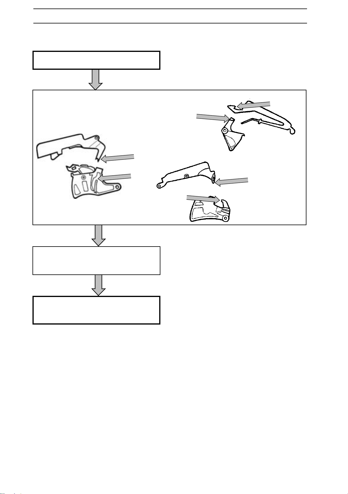
Cleaning and inspection
Clean all parts.
Check that the lock's activation
mechanism is not worn. For examples of
the activation mechanism, see the figure.
Check that the springs, where fitted, are
OK and have the correct tension.
On those saws fitted with a throttle cable, check
that the cable and lever are OK and run freely.
54 – English
www.mymowerparts.com
Page 55
For Husqvarna Parts Call 606-678-9623 or 606-561-4983
SAFETY EQUIPMENT
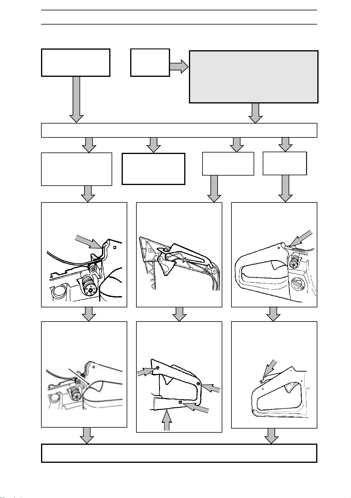
Assembly
Saws 36, 40, 41, 45, 42,
242XP, 246, 51, 55,
254XP , 257 and 262XP.
Saws 36, 41, 42, 242XP ,
246, 51, 55, 254XP , 257,
262XP and 394.
On saw 394, fit the cable
to the trigger. Insert them
into the handle from the
front.
Other saws.
!
Fit springs in appropriate cases.
Saws 61, 268, 268K,
272XP , 272K, 272S,
281XP and 288XP.
See next page.
Fit the cable to the trigger
and install the throttle lock
and trigger.
WARNING!
The fuel used in the chain saw
poses the following hazards:
1. The liquid and its vapours
are poisonous.
2. Can cause skin irritation.
3. Is highly inflammable.
Saws 40, 45.
Fit the trigger with the cable
from the front.
Saw 3120.
Fit the pin (B) and spring
(when used).
B
All saws except 40 and 45 continue on the next page.
www.mymowerparts.com
Fit the side of the handle
using three screws on the
side and one underneath,
which holds the spring.
Fit the spring and slide the
throttle lock forwards from
above so that its rear edge
can be slid in under the edge
of the handle.
English – 55
Page 56
For Husqvarna Parts Call 606-678-9623 or 606-561-4983
SAFETY EQUIPMENT
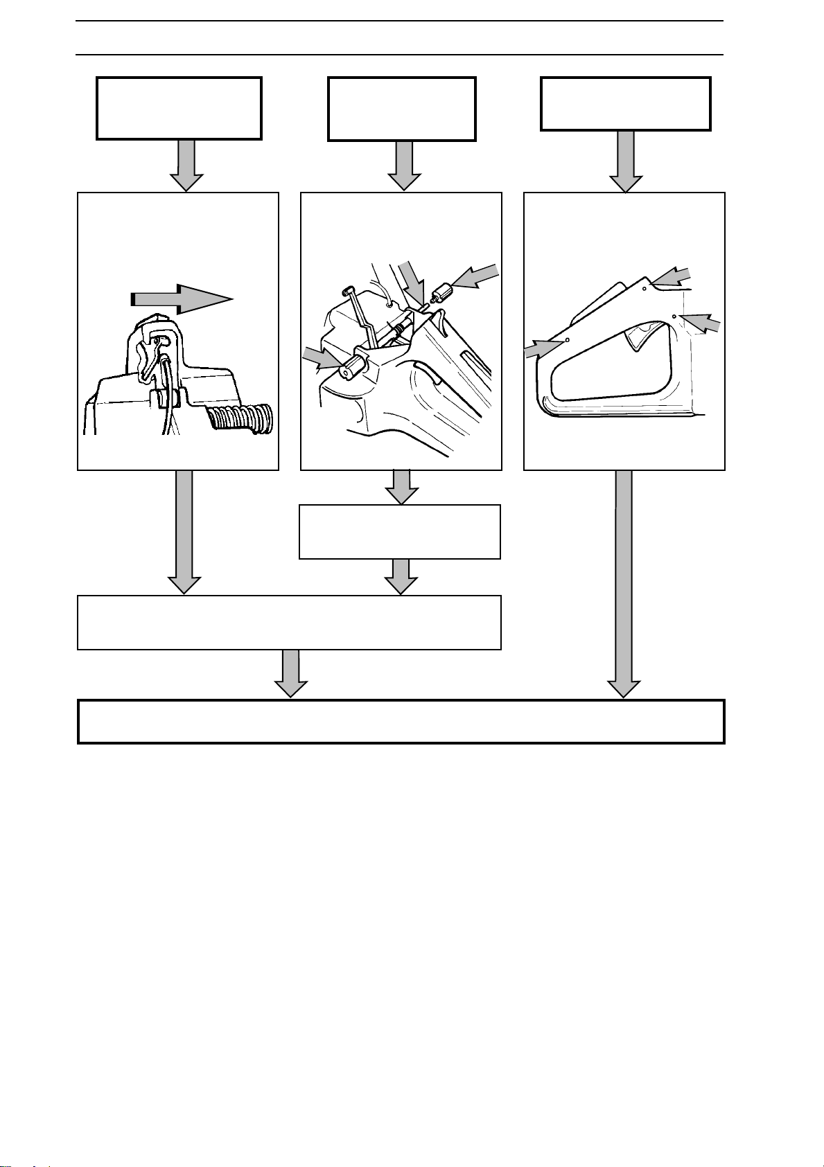
Saws 36, 41, 42, 242XP ,
246, 51, 55, 254XP , 257,
262XP and 394.
Fit the throttle lock and
spring. On saw 394, twist
as shown in the figure
when fitting.
Saws 61, 268, 268K,
272XP , 272K, 272S,
281XP and 288XP.
Fit the throttle arm and
spring. Fit the pin and the
two rubber dampers.
Saw 3120.
Fit the three pins that hold
the cable bracket, throttle
lock and trigger.
Fit the throttle lock from the
front.
Fit the throttle lock pin.
Fit the tank unit. See page 105.
56 – English
www.mymowerparts.com
Page 57
For Husqvarna Parts Call 606-678-9623 or 606-561-4983
STARTER
Dismantling
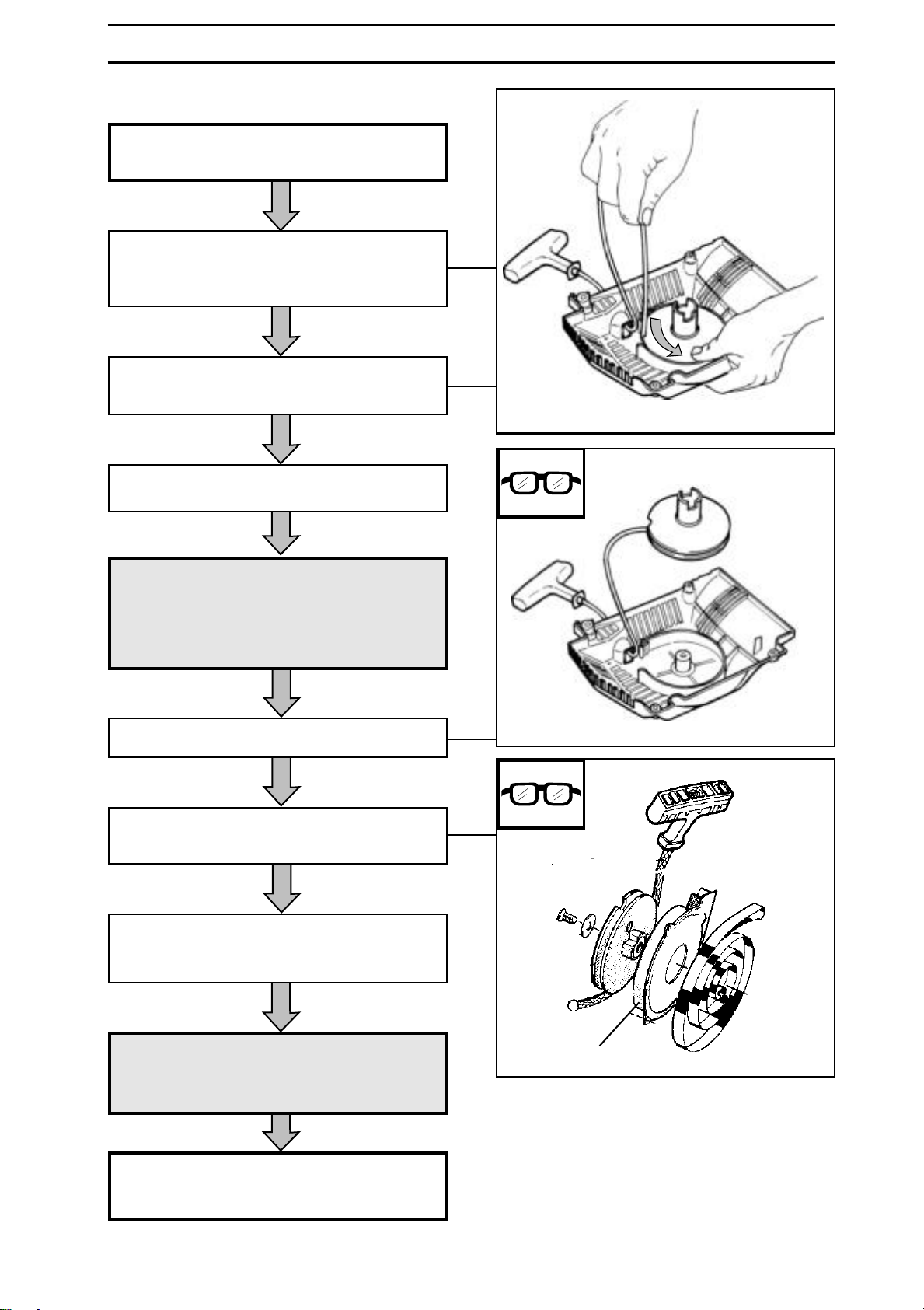
Dismantle the starter
See the operating instructions.
Pull out the cord 20-30 cm andinsert it into
the cut-out in the starter pulley rim.
Some saws have several long cut-outs.
Rotate the starter pulley anticlockwise until
the spring-tension on the starter pulley ceases.
Dismantle the starter pulley's centre bolt and
washer.
WARNING!
If the spring tension is released
!
Lift out the starter pulley carefully.
If the starter has a cord guide (A), remove
this
If the cord is to be replaced, cut it off and pull
out the bits from the handle and starter pulley
using a pair of long nosed pliers.
when lifting the starter pulley, the
spring can fly out and cause personal injury!
Wear protective glasses!
WARNING!
!
If the spring is to be replaced, remove the old
spring from the starter pulley. Some saws
have a protective plate over the spring.
Ensure that the spring does not
fly out and cause personal injury!
Wear protective glasses!
www.mymowerparts.com
A
English – 57
Page 58
For Husqvarna Parts Call 606-678-9623 or 606-561-4983
STARTER
Cleaning and Inspection
WARNING!
!
Ensure that the spring does not
fly out and cause personal injury!
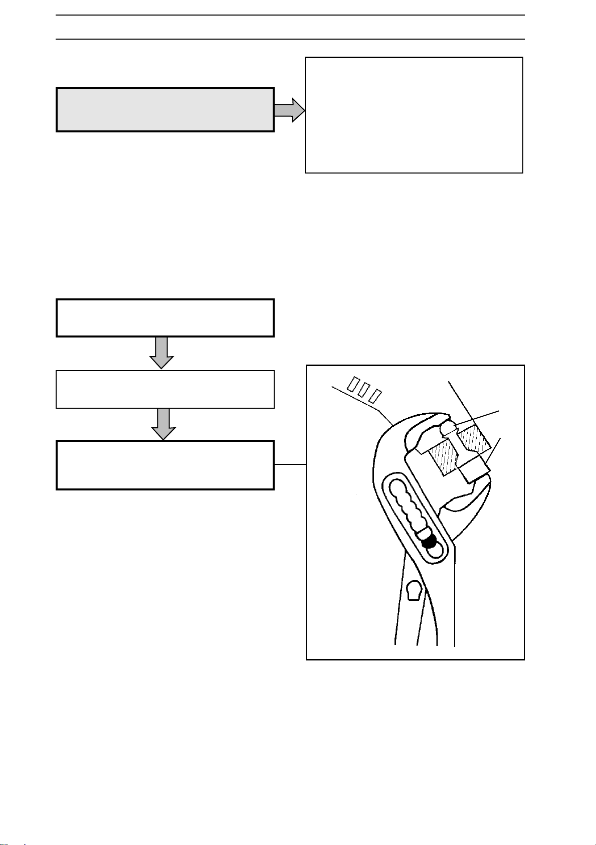
Changing the ferrule
Remove the parts of the old ferrule.
Clean all parts and check the following:
The starter cord.
The dogs in the starter pulley.
That the pawls on the flywheel are OK, and
spring back towards the centre and move freely.
Fit the new ferrule in the starter housing.
Use a wrench, spacer (A) and ball (B).
Splay out the ferrule on the inside as
shown in the figure.
B
A
58 – English
www.mymowerparts.com
Page 59
For Husqvarna Parts Call 606-678-9623 or 606-561-4983
STARTER
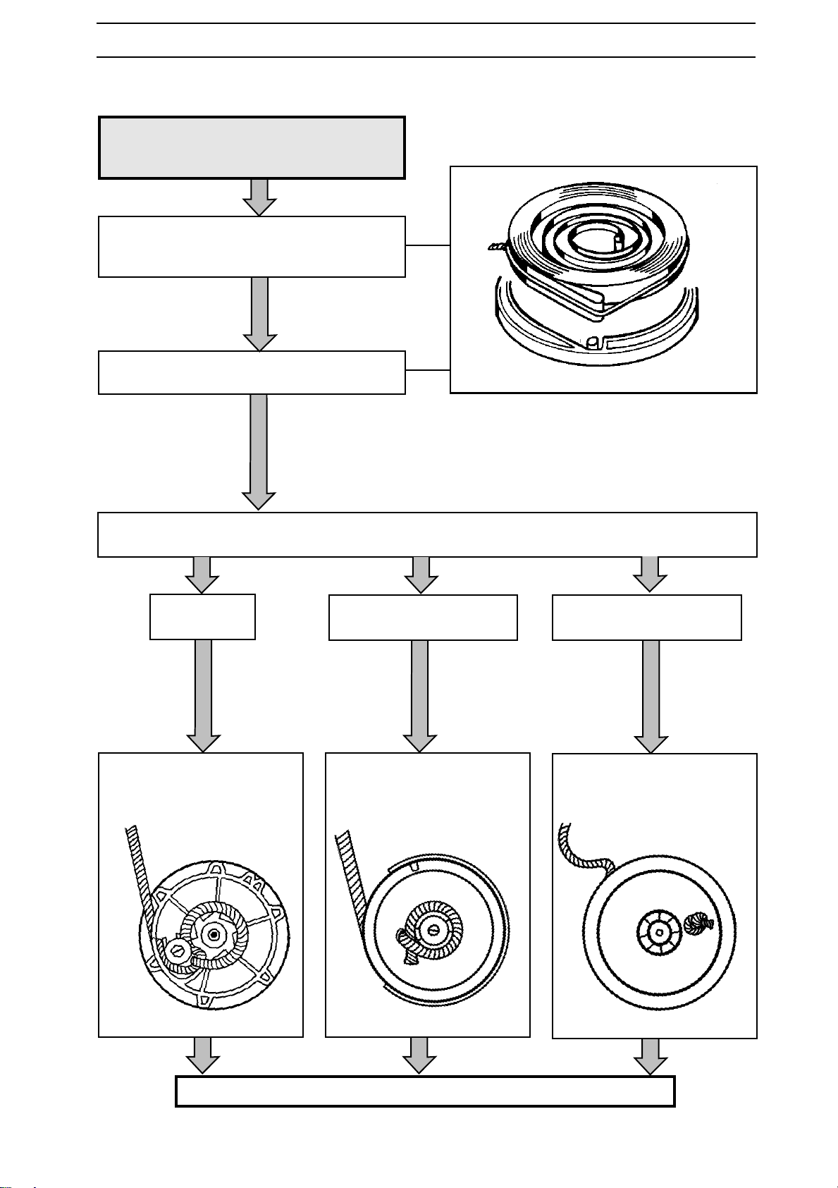
Assembly
WARNING!
!
If a new spring is to be fitted, position in its
security/holder so that the eye is over the
stud in the starter cover.
Slide in the spring and remove the security/
holder.
Ensure that the spring does not
fly out and cause personal injury!
If a new cord is to be fitted, put the free end in the hole on the starter pulley . Grip the end using long
nosed pliers and pull the cord through.
36 and 41.
Screw the cord to the starter
pulley .
61, 268, 272, 281 and 288.
Secure the cord on the
starter pulley.
42, 242, 246, 51, 55, 254,
257,262, 394 and 3120.
Knot the cord on the starter
pulley .
Continues on next page.
www.mymowerparts.com
English – 59
Page 60
For Husqvarna Parts Call 606-678-9623 or 606-561-4983
STARTER
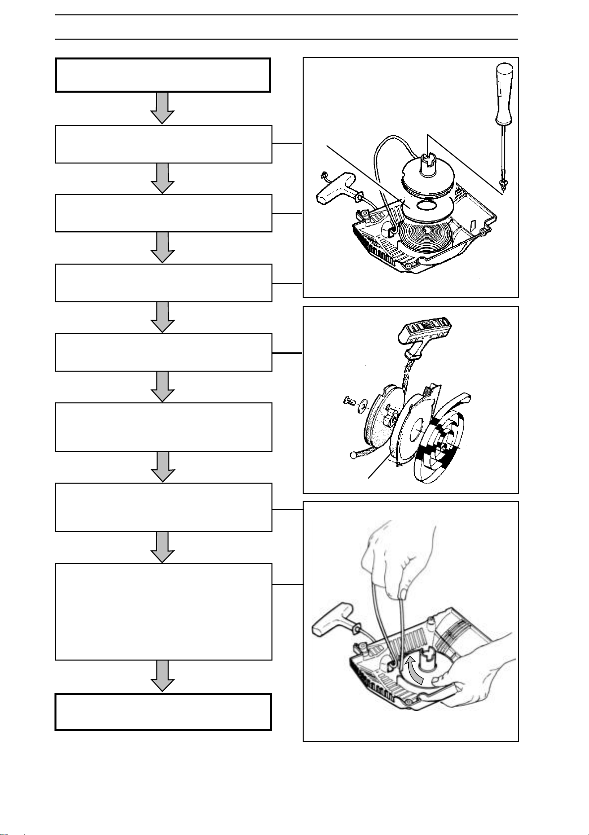
Grease the return spring and starter pulley
bearing.
If the starter unit has a cover plate (B) over
the spring, fit the plate.
Fit the starter pulley. Rotate back and forth
until the starter pulley catches in the spring.
Fit the starter pulley washer and bolt and
tighten the bolt to 4 Nm.
If the starter has a cord guide (A), fit this.
Pull out the cord through the hole in the cover
and fit the handle, secure with a double knot.
B
Pull out the cord 20-30 cm and insert it into
the cut-out on the starter pulley rim. Some
saws have several long cut-outs.
Rotate the starter pulley clockwise until the
cord is correctly tensioned.
Check the cord tension
A. Pull out the cord completely and hold the
pulley with your thumb.
B. In this position it should be possible to turn
the starter pulley a further 1/2 - 3/4 turn.
Fit the starter on the crankcase. Tighten the
bolts to 4 Nm.
A
60 – English
www.mymowerparts.com
Page 61
For Husqvarna Parts Call 606-678-9623 or 606-561-4983
ELECTRICAL SYSTEM
Ignition system
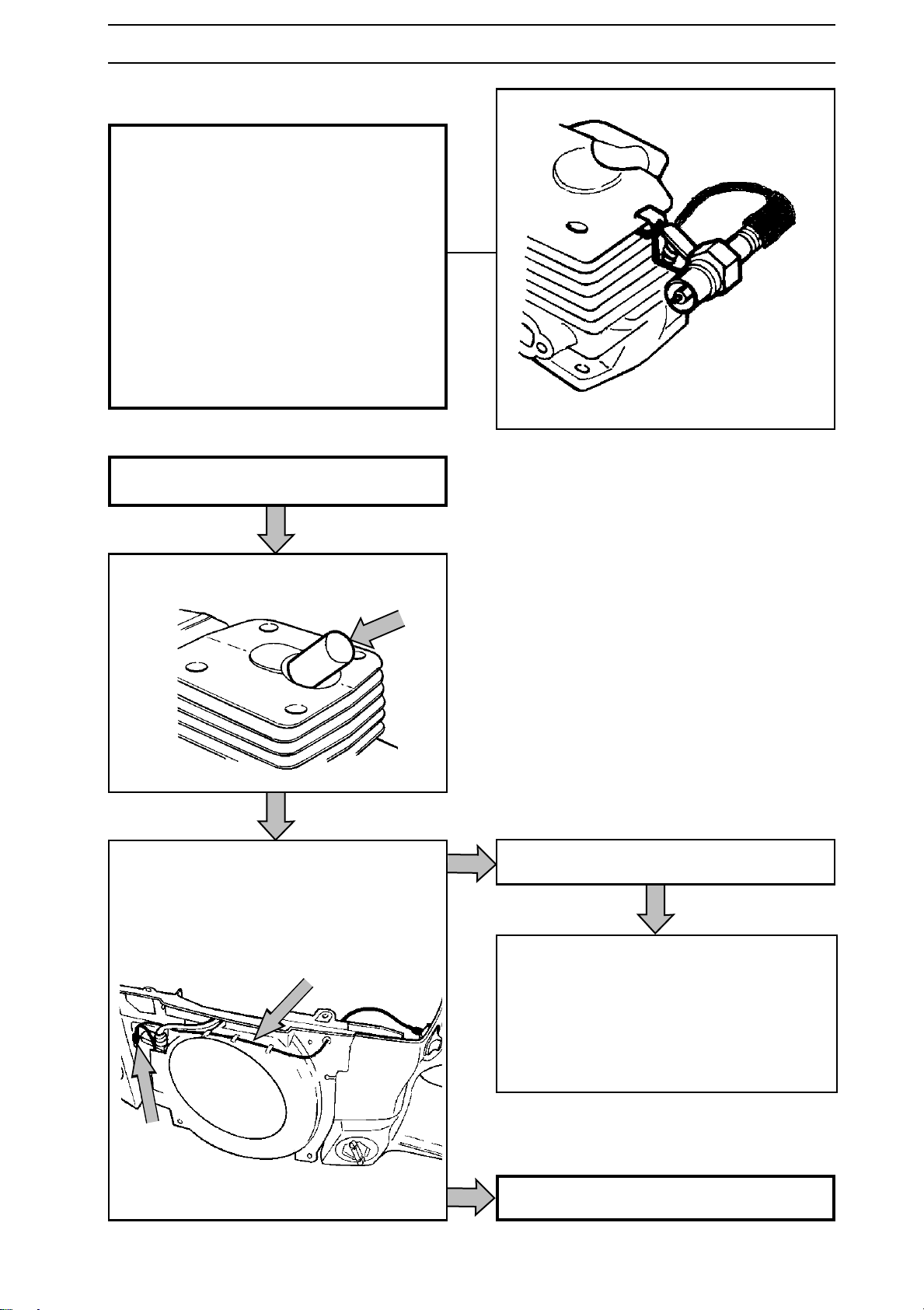
In the event of a fault in the ignition system
the ignition module should be checked before
dismantling the ignition system.
Check the ignition module as follows:
• Connect test spark plug 502 71 13-01 to the
HT lead and clamp the test spark plug to the
cylinder.
• Turn the engine over using the starter.
• If the test spark plug sparks the ignition
module is OK.
Dismantling
Remove the cylinder cover and the starter unit.
Remove the spark plug and fit the piston stop.
Loosen the cable that runs to the stop
switch from the ignition module.
Saws 36 and 41.
Release the cables from the guide rail and
remove the guide rail.
www.mymowerparts.com
• Loosen the flywheel nut and unscrew it 1
turn
• Tap the nut quickly with a hammer so that
the flywheel comes loose
• Remove the nut and flywheel.
Other saws, see next page.
English – 61
Page 62
For Husqvarna Parts Call 606-678-9623 or 606-561-4983
ELECTRICAL SYSTEM
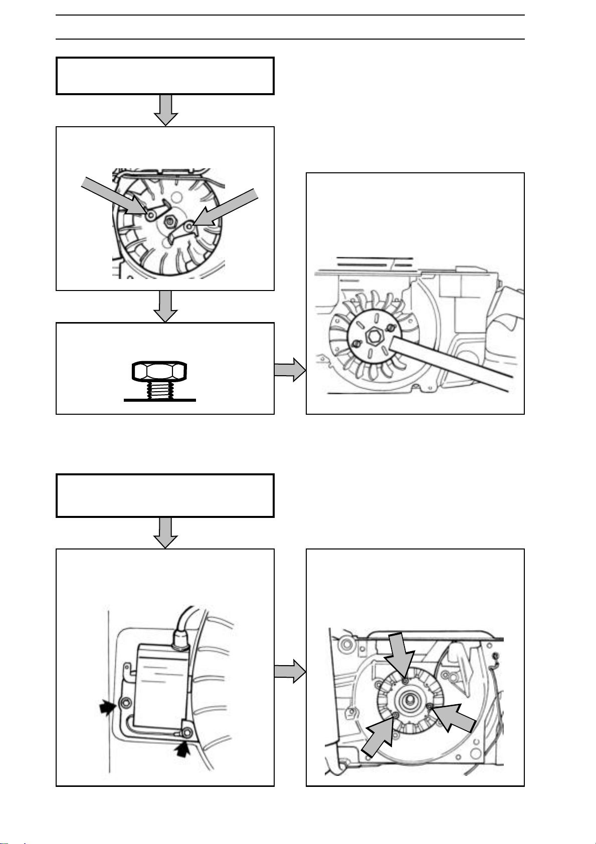
All saws except 36 and 41.
Unscrew the two pawls and springs
located on the flywheel.
Fit puller 502 51 49-02 and loosen the
flywheel.
Remove the puller, nut and flywheel.
Loosen the flywheel nut and undo until it
aligns with the end of the shaft.
Continuation all saws
Remove the ignition coil.
The generator can be unscrewed if the saw is
fitted with a handle heating system.
Remove all parts so that the cable can be
released. See applicable sections.
62 – English
www.mymowerparts.com
Page 63
For Husqvarna Parts Call 606-678-9623 or 606-561-4983
ELECTRICAL SYSTEM
Cleaning and Inspection
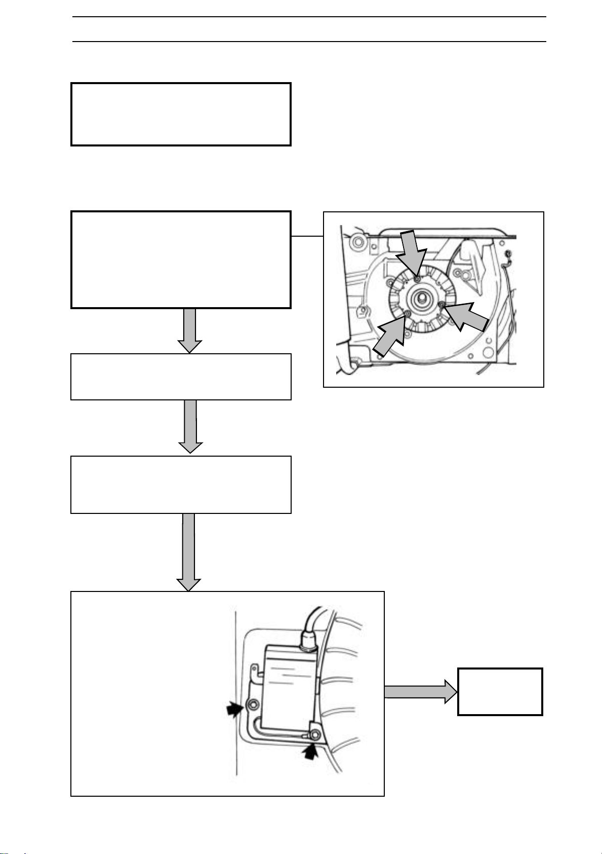
Clean all parts, especially the flywheel and
shaft taper.
Check that the flywheel is not cracked or
damaged in any other way.
Assembly
Fit the generator if the saw is fitted with
handle heating.
Tighten the bolts to 4 Nm and lock using
Loctite.
Fit the cable to the actual contact on the
saw. Adjust the length of the cable by
knotting it.
Place the flywheel on the crankshaft. Rotate
gently until the flywheel's key mates in the
keyway on the shaft
• Replace the flywheel washer and nut.
Tightening torque, see "Service data".
• Remove the piston stop.
• Fit the ignition module
without tightening the
screws.
• Turn the flywheel so that its
magnet is beside the
ignition module.
Continue
assembly on
next page.
www.mymowerparts.com
English – 63
Page 64
For Husqvarna Parts Call 606-678-9623 or 606-561-4983
ELECTRICAL SYSTEM
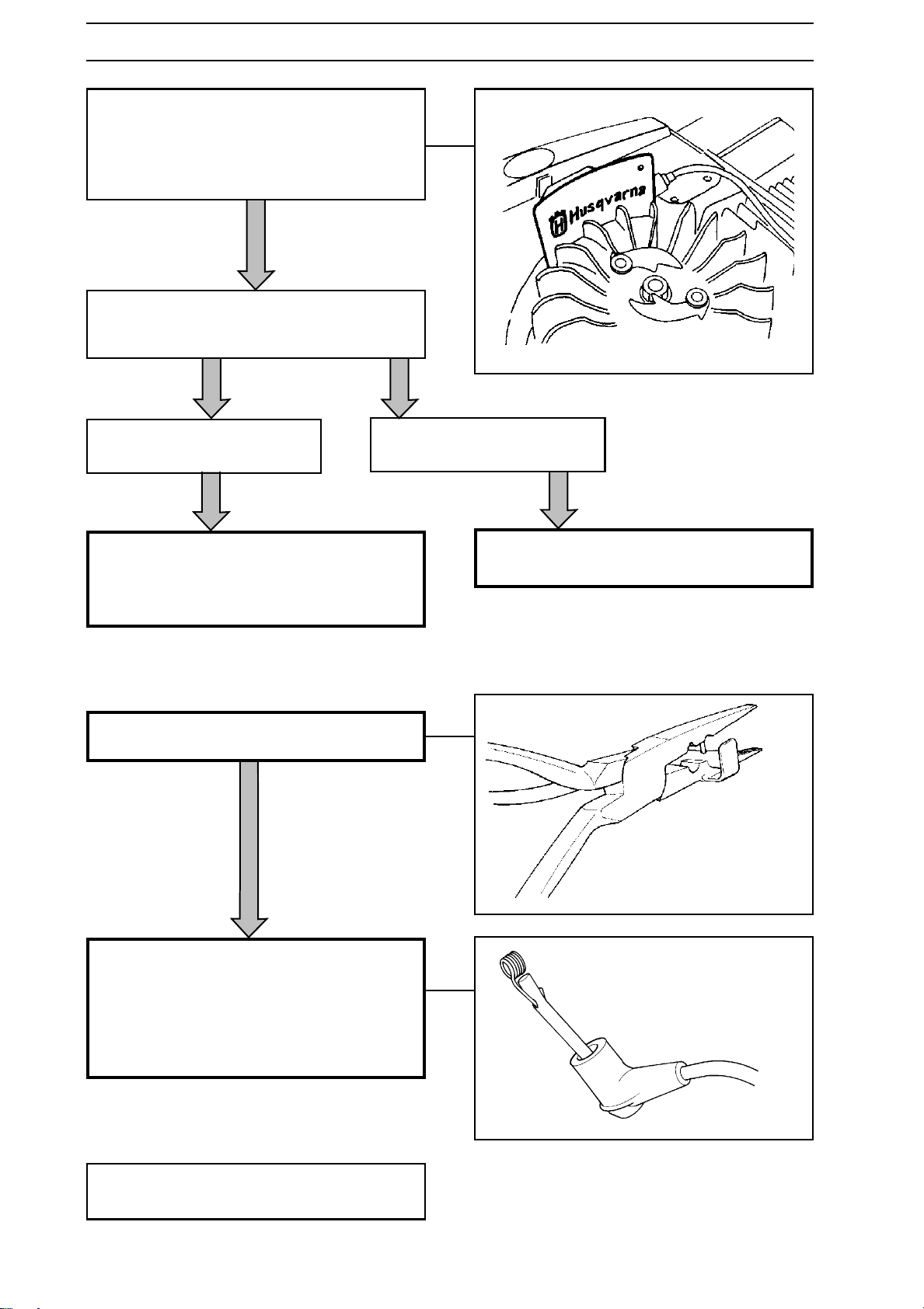
• Insert feeler gauge 502 51 34-02
(0.3 mm) between the ignition module
and the flywheel's magnet.
• Push the ignition module towards the
flywheel and tighten the bolts to 4 Nm.
Fit the guide rail, insert the cables and fit
the cable to the ignition module.
Saws 42, 242, 246, 281 and 288.
Fit the ignition coil, which is located next to
the carburettor and connect the cables.
Fit the starter and cylinder cover.
Fitting the spark plug cover
Make a hole in the HT cable using pliers
502 50 06-01.
Other saws.
Fit the starter and cylinder cover.
Push the HT cable through the spark plug
cover and fit the contact spring using the
pliers.
Slide the spark plug cover over the contact
spring.
Stop switch
The stop switch is described in the section
"Safety equipment". See page 51.
64 – English
www.mymowerparts.com
Page 65
For Husqvarna Parts Call 606-678-9623 or 606-561-4983
ELECTRICAL SYSTEM
Handle heating
Description
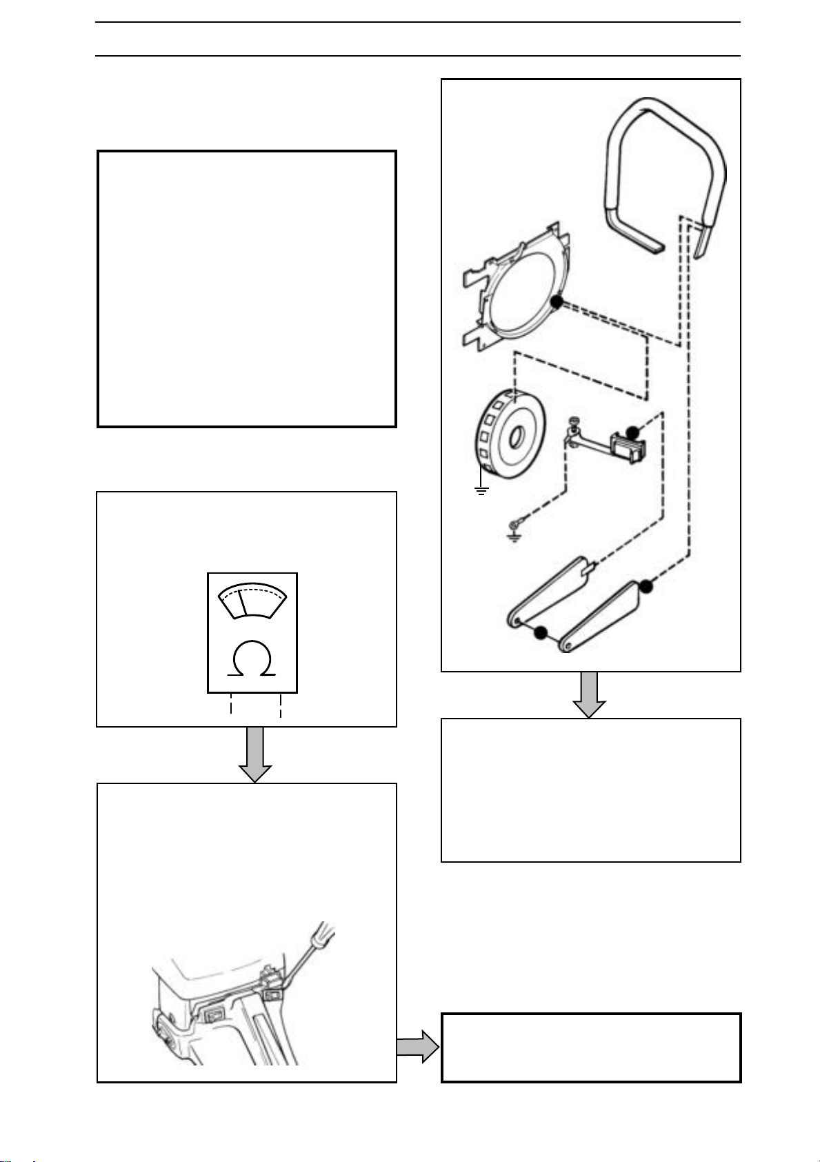
Some saws are equipped with an electric
handle heating. This consists of the following
parts:
• Generator.
• Power switch.
• Heater loop in the tank unit.
• Handle loop with heater loop.
(One or two loops).
The above components are connected in
series, which means that if there is a fault in
one, all components stop working.
The wiring diagram is shown in the figure to
the right. The order of components can vary
from saw to saw.
B
E
Trouble shooting
Trouble shooting can take place with most
components connected to the saw. An
ohm meter is required for trouble shooting.
Before trouble shooting individual
components remove the power switch and
disconnect one of the switch's cables.
Remove other components as necessary.
E.g. the cylinder cover. See the operating
instructions.
A1
A2
C
D
Measurement points:
A1 and A2 Earth. E.g. the cylinder
A1 - B Measurement of the generator
B - C Measurement of the handle loop
C - D Measurement of the heater loops
in the rear handle
D - A2 Measurement of the power switch
Trouble shooting individual components, see
next page.
www.mymowerparts.com
English – 65
Page 66
For Husqvarna Parts Call 606-678-9623 or 606-561-4983
ELECTRICAL SYSTEM
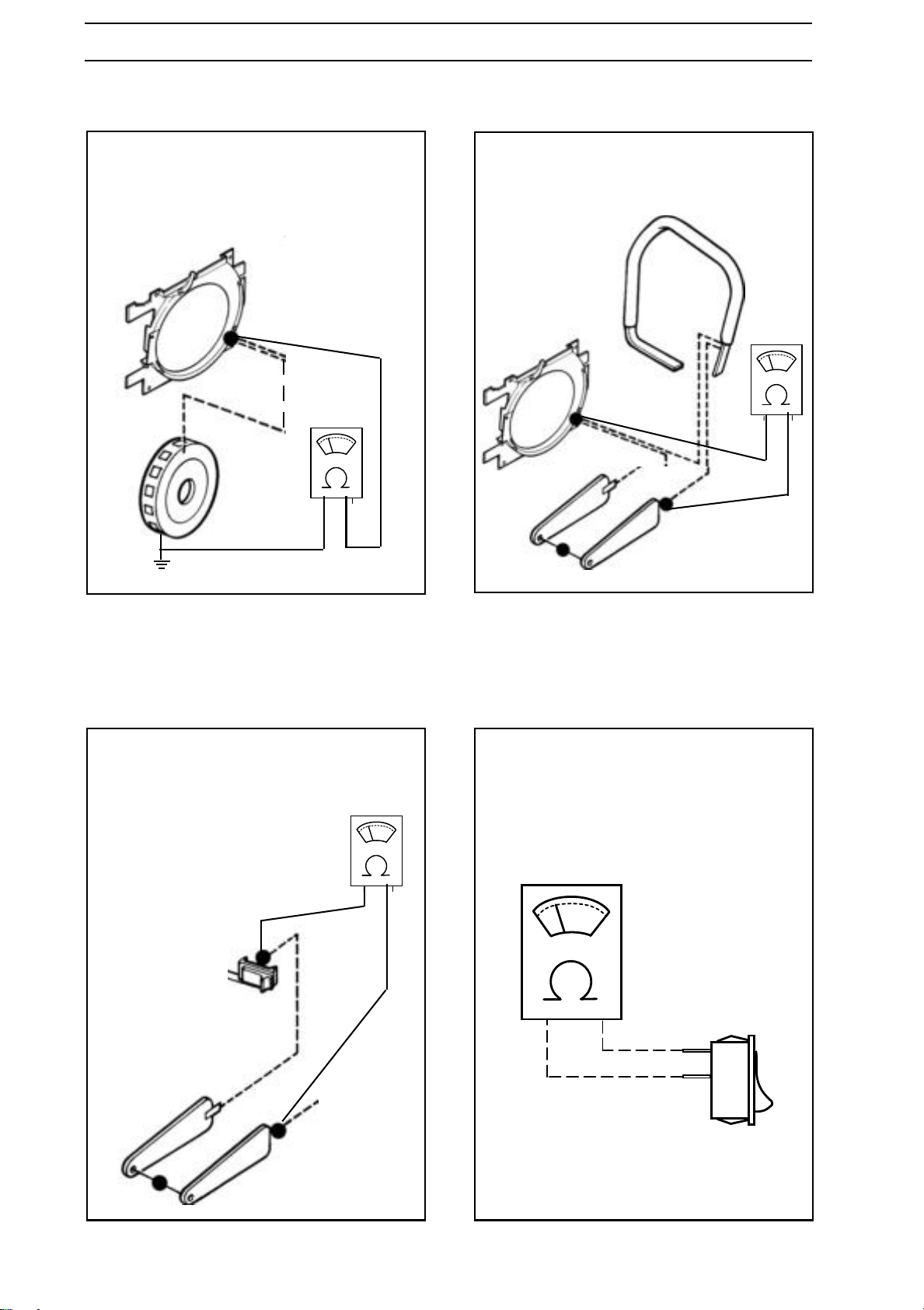
Checking the generator
Connect the ohm meter to the cylinder
(point A1) and point B. The ohm meter
should read 0.9-1.3 ohm.
Replace a generator that has higher or
lower values.
B
Check the handle loop
Connect the ohm meter to points B and C.
The ohm meter should read 3-4 ohm.
Replace the handle loop that has a higher
value.
B
C
A1
Checking the heat loops in the rear handles
Connect the ohm meter to points C and D.
The ohm meter should read 0.7-2.5 ohm.
Replace a heat loops that has higher
values.
D
Checking the power switch
Connect the ohm meter across the switch.
The ohm meter should read more than
1000 ohm with the switch in position "0".
The ohm meter should read, at the highest,
0.1 ohm with the switch in position "1".
66 – English
C
www.mymowerparts.com
Page 67
For Husqvarna Parts Call 606-678-9623 or 606-561-4983
CENTRIFUGAL CLUTCH
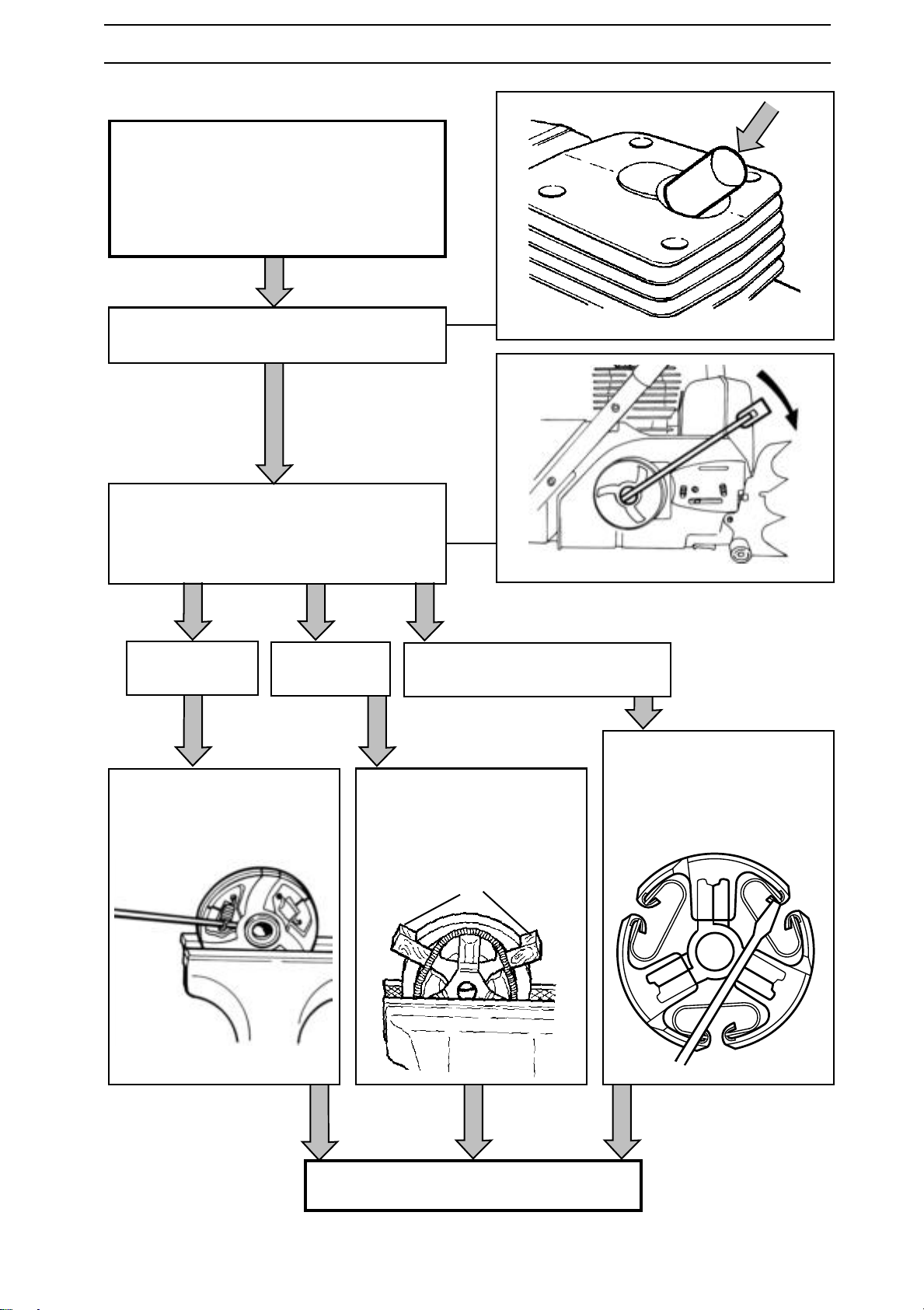
Dismantling
Remove the bar and chain. See the operating instructions.
On 268K and 272K, remove the cutting
attachment. See the operating instructions.
On 272S, remove the grinder attachment.
See the operating instructions.
Remove the spark plug and insert the piston
stop.
Use a spanner and remove the clutch. On
saws 36 and 41 use the service tool no. 530
03 11-12.
Note! Left-hand thread.
Saws with three
coil springs.
Remove the springs using a
screwdriver.
Then remove the clutch
shoes.
Saws with one
long spring.
Remove the spring by first
lifting a shoe using a suitable
spacer (A).
Then remove the clutch
shoes.
Saws with three C-springs.
Prise out the spring heels
using a screwdriver. Remove
the springs from the other
side using circlip pliers. Then
remove the clutch shoes.
A
Remove the clutch drum and needle bearing.
www.mymowerparts.com
English – 67
Page 68
For Husqvarna Parts Call 606-678-9623 or 606-561-4983
CENTRIFUGAL CLUTCH
Cleaning and Inspection
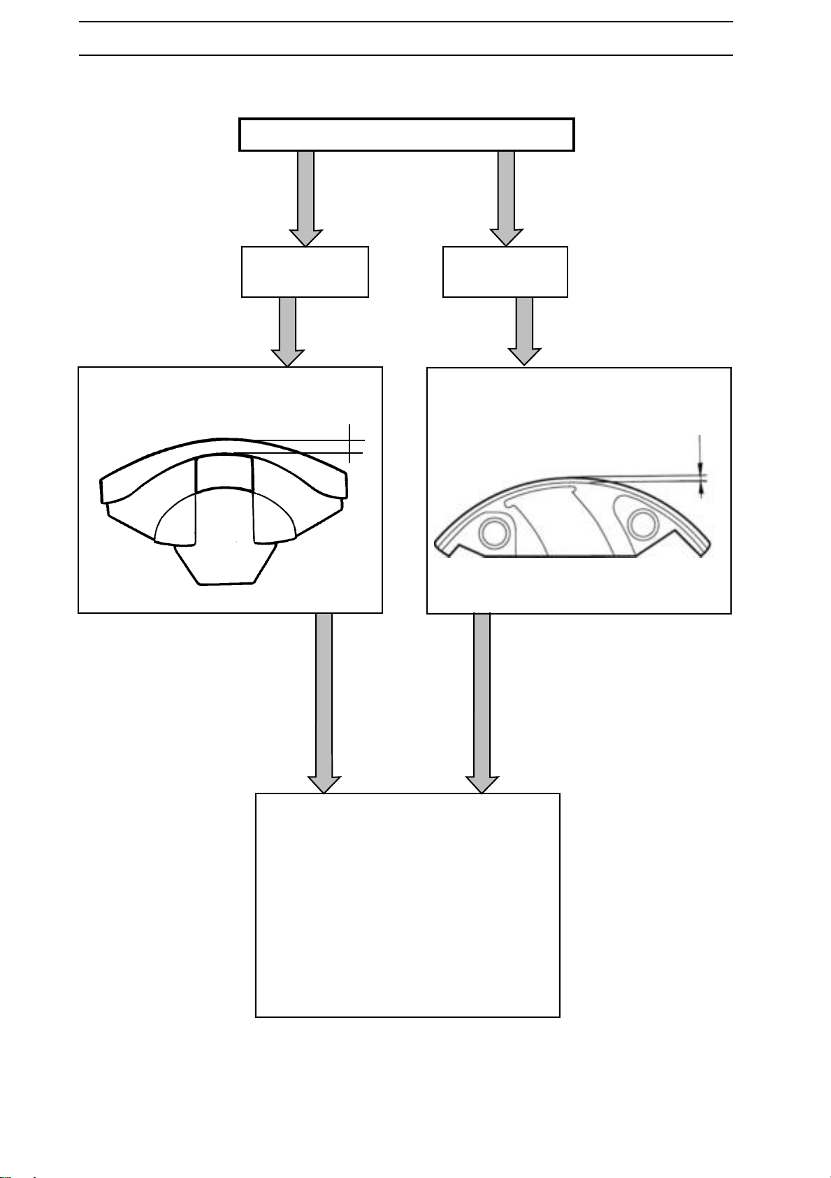
Clean all parts and inspect the following:
Clutch shoes
without chamfers.
That measurement A is not below 1 mm.
A
Clutch shoes
with chamfers.
That measurement B is not under 1 mm.
B
68 – English
Check that there is no play between the
clutch shoe and clutch hub
Check for wear on the chain sprocket.
Check the condition of the needle bearing
and the bearing surface on the crankshaft.
That the clutch drum friction surface and
bearing surface are undamaged.
www.mymowerparts.com
Page 69
For Husqvarna Parts Call 606-678-9623 or 606-561-4983
CENTRIFUGAL CLUTCH
Assembly
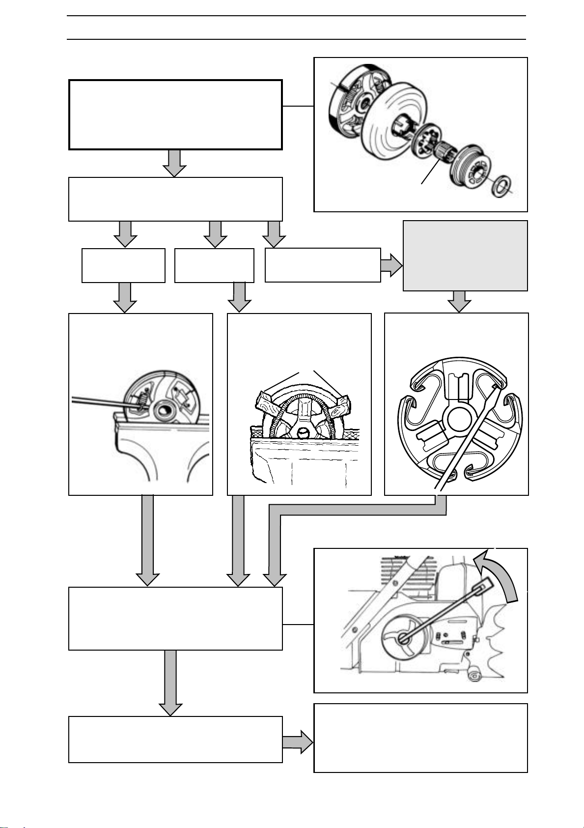
Grease the needle bearing (C) and fit onto
the crankshaft. Then fit the clutch drum.
NOTE! The bearing can also be greased
later through the hole on the crankshaft.
T o prevent imbalance all clutch shoes should
be replaced at the same time.
Saws with three
coil springs.
Locate the clutch shoes on
the hub and fit the springs
with the help of pliers.
Saws with one
long spring.
Locate the clutch shoes on the
hub. Lift a shoe using a suitable spacer (A) and fit the
spring.
Saws with three C-springs.
A
C
NOTE! The clutch
springs should not be
opened out more than
necessary. Risk of
deformation.
Locate the clutch shoes on the
hub and fit the springs with the
help of circlip pliers.
Using a spanner secure the clutch centre.
On saws 36 and 41 use service tool no.
530 03 11-12.
Note! Left-hand thread.
Remove the piston stop and fit the spark
plug.
www.mymowerparts.com
Fit the chain and bar. See the operating instructions. On 268K and 272K, fit the cutting attachment.
See the operating instructions.
English – 69
Page 70
For Husqvarna Parts Call 606-678-9623 or 606-561-4983
LUBRICATION SYSTEM
Dismantling
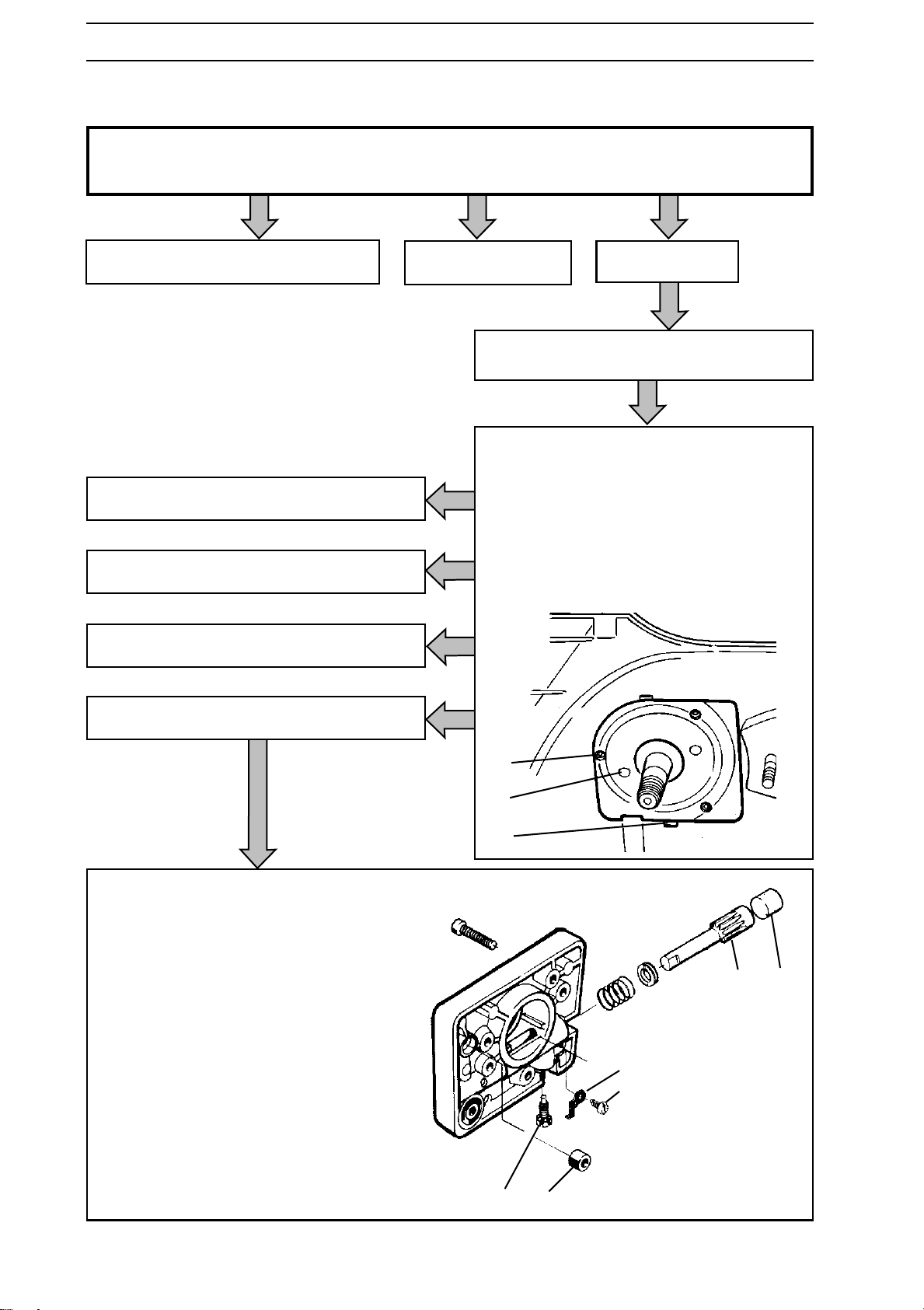
Dismantle the following parts: • Starter. See the operating instructions
• Centrifugal clutch. See page 67.
Saws 36, 40, 41, 45, 51 and 55. See page 72
Saws 61, 268, 272XP. See next page.
Saws 281XP and 288 XP. See next page.
Saw 394. See page 72.
Saw 3120. See page 72
Remove the pump drive and washer.
Undo the three bolts (A) and remove the
oil pump. Some pumps have to be
removed by using extractor screws. M5
screws should be inserted into the 2
threaded holes in the pump body and
tightened equally to lift the pump and
thrust washer. Other pumps have a cut-out
(C) for a screwdriver to prise off the pump.
Both types are shown below.
Other saws.
Saws 42, 242XP, 246, 254XP, 262XP and 257.
Dismantle the oil pump as follows:
1. Unscrew screw (A) and remove locking
clip (B).
2. Undo screw (C).
3. Lever out the pump piston (D) and
plastic plug (E) using a screwdriver.
4. Remove the seal (F).
A
B
C
DE
B
A
70 – English
CF
www.mymowerparts.com
Page 71
For Husqvarna Parts Call 606-678-9623 or 606-561-4983
LUBRICATION SYSTEM
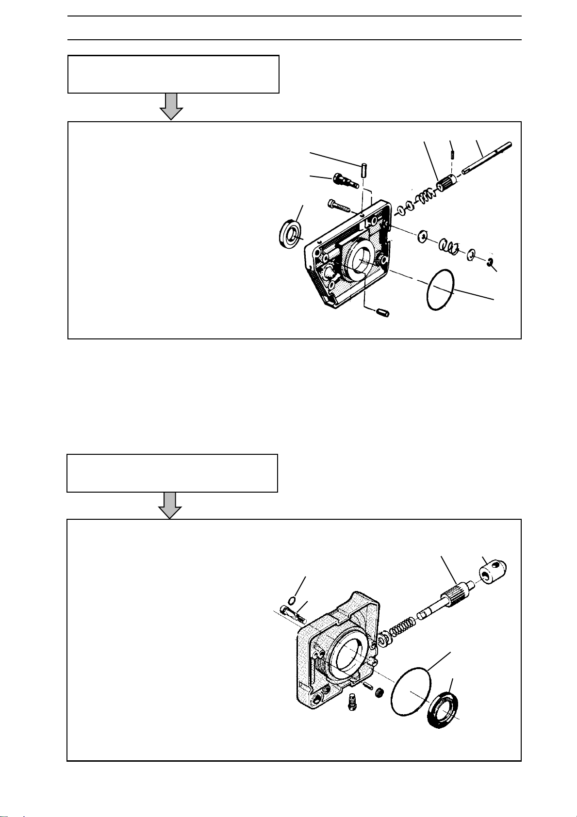
Saws 61, 268, 272XP.
Dismantle the oil pump as follows:
1. Remove the lock washer (A), washer,
spring and adjuster screw (B).
2. Remove the locking lacquer and undo
screw (C).
3. Knock the edge of the pump housing
against a piece of wood so that the
pump piston (D) slides out of the
housing.
4. Remove the pinion (E) with washers
and springs.
5. Remove the pin (F).
6. Remove the seal (G).
7. If necessary remove the O-ring (H).
E C D
F
B
G
A
H
Saws 281XP and 288 XP.
Dismantle the oil pump as follows:
1. Undo the adjuster screw (A).
2. Remove the plug (B) with pump piston
(C) and spring with washers.
3. Dismantle the O-ring (D). Replace if
necessary.
4. If necessary, replace the seal (E).
5. If necessary, replace the O-ring (F).
CB
F
A
D
E
www.mymowerparts.com
English – 71
Page 72
For Husqvarna Parts Call 606-678-9623 or 606-561-4983
LUBRICATION SYSTEM
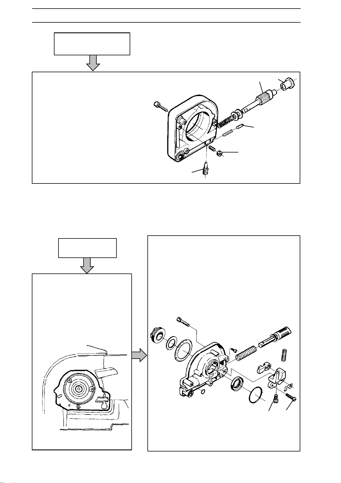
Saw 394.
Dismantle the oil pump as follows:
1. Dismantle the screw (A) so that the
spring and latch pin (B) can be
removed.
2. Lever out the pump piston (C) with the
plastic plug (D) using a screwdriver.
3. Remove the seal (E).
Saw 3120.
CD
B
E
A
Dismantle the oil pump as follows:
Undo the three bolts that hold
the oil pump and lift up the pump
by the cut-out for the adjuster
screw. Lift off the pump and
loosen the wire for manual oil
supply.
1. Undo the screws (A) and remove the parts as
shown in the figure below.
2. Undo screw (B). NOTE! Left-hand thread.
BA
72 – English
www.mymowerparts.com
Page 73
For Husqvarna Parts Call 606-678-9623 or 606-561-4983
LUBRICATION SYSTEM
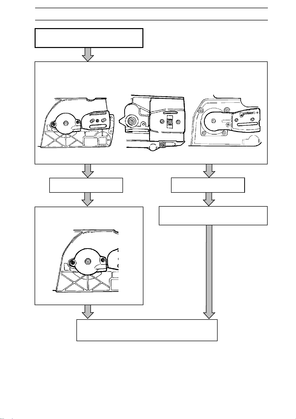
Saws 36, 40, 41, 45, 51 and 55.
Dismantle the chain guide plates as shown
in respective diagrams below.
36/41 40/45 51/55
Saws 36, 40, 41 and 45.
Undo the two bolts and lift off the pump
and the upper seal.
Saws 51 and 55.
Lift off the pump and the upper seal.
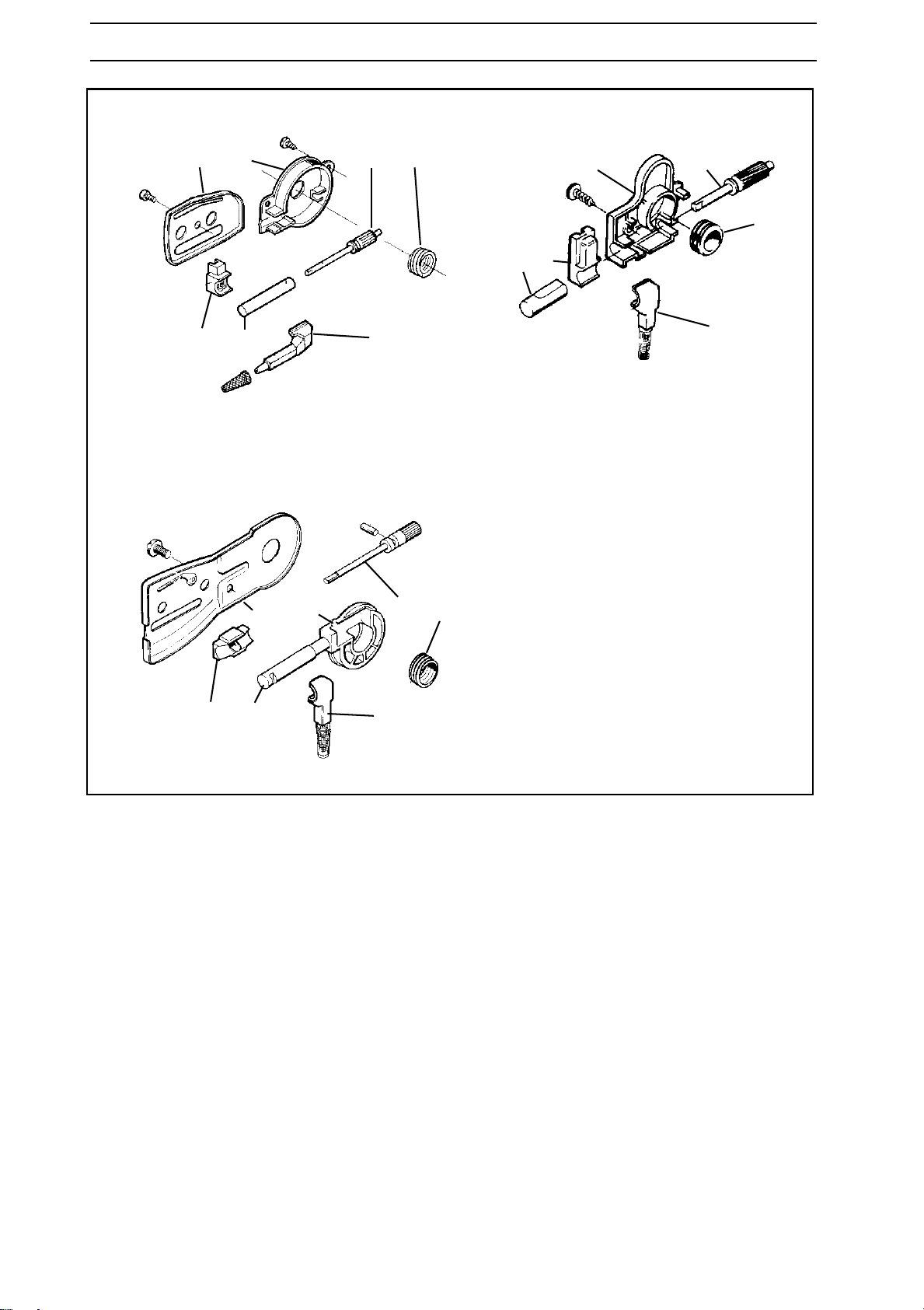
Take the pump apart as shown in the exploded view on
the next page.
www.mymowerparts.com
English – 73
Page 74
For Husqvarna Parts Call 606-678-9623 or 606-561-4983
LUBRICATION SYSTEM
36/41
D E F G
CB A
D E F G
E F
G
B C
A
40/45
A. Lower seal.
B. Pump cylinder.
C. Upper seal.
D. Chain guide plate.
E. Pump housing.
F. Pump piston.
G. Worm gear.
50/51
CB A
74 – English
www.mymowerparts.com
Page 75
For Husqvarna Parts Call 606-678-9623 or 606-561-4983
LUBRICATION SYSTEM
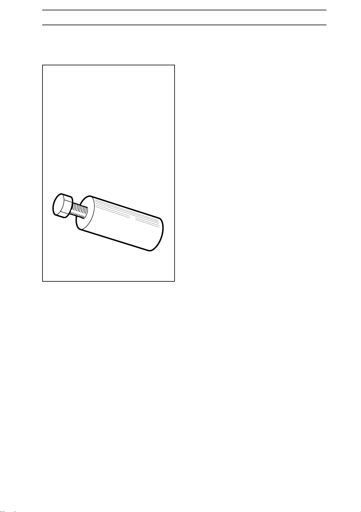
Dismantling the oil pump's
worm gear
On some saws the worm gear for the oil
pump is pressed on the crankshaft.
Remove the worm gear by using the
service tool for the saw in question. See
"Tools".
First screw the tool onto the entire worm
gear
Turn the screw until the worm gear is
removed.
www.mymowerparts.com
English – 75
Page 76
For Husqvarna Parts Call 606-678-9623 or 606-561-4983
LUBRICATION SYSTEM
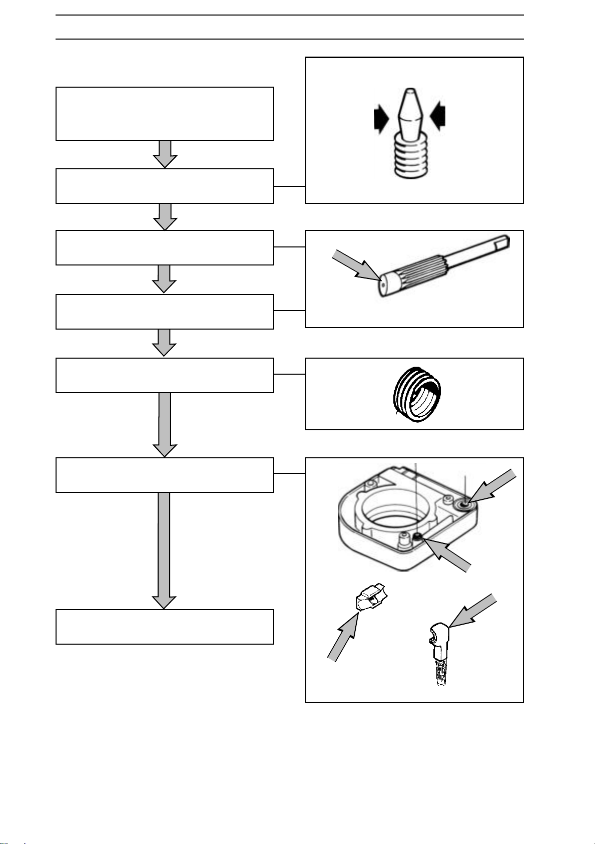
Cleaning and Inspection
Clean all parts and check the following
when appropriate to the saw in question.
That the taper on the adjuster screw
shows no signs of wear.
That the pump piston's eccentric face does
not show signs of wear.
That the pump piston's pinion gear is undamaged.
That the worm gear on the oil pump drive
is undamaged.
That all seals are undamaged.
The oil pipe is not blocked and the filter
screen is clean.
76 – English
www.mymowerparts.com
Page 77
For Husqvarna Parts Call 606-678-9623 or 606-561-4983
LUBRICATION SYSTEM
Assembling the worm gear
On those saws where the oil pump worm
gear is pressed on the crankshaft.
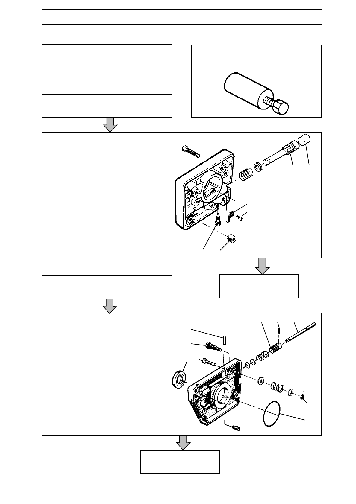
Assembling the oil pump
Saws 42, 242XP, 246, 254XP, 262XP and 257.
Fit the oil pump as follows:
1. Apply SAE 30 oil to all moving parts.
2. Insert the pump piston (D) with
washers and spring.
3. Press in the pump piston a little more
and screw in the adjuster screw (C).
4. Insert the plastic plug (E).
5. Refit screw (A) and locking clip (B).
6. Fit the seal (F).
Screw the worm gear into the dismantling
tool and press the worm gear onto the
crankshaft until it bottoms against the
collar.
DE
B
A
Saws 61, 268, 272XP.
Fit the oil pump as follows:
1. Apply SAE 30 oil to all moving parts.
2. Fit the seal (G) if necessary.
3. Press in pin (F).
4. Locate the pinion (E) with washers and
spring.
5. Insert the pump piston (D) through the
pinion, spring and washers in the pump
housing.
6. Fit screw (C). The screw should be
locked using Loctite or locking lacquer.
7. Fit the adjuster screw (I) with washers,
spring and locking clip (A).
8. Fit the O-ring (H).
CF
F
B
I
G
See continuation, page 80.
E C D
A
H
See continuation, page 80.
www.mymowerparts.com
English – 77
Page 78
For Husqvarna Parts Call 606-678-9623 or 606-561-4983
LUBRICATION SYSTEM
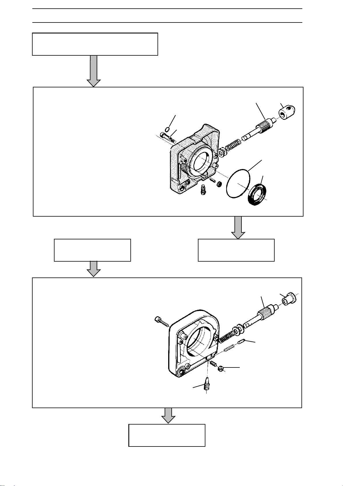
Saws 281XP and 288 XP.
Fit the oil pump as follows:
1. Apply SAE 30 oil to all moving parts
2. Fit the seal (E) if necessary.
3. Fit the plug (B) and spring with washers
on the pump piston (C) and fit the unit
in the pump housing.
4. Fit the adjuster screw (A) in the pump
housing, and through the hole in plug
(B).
5. Fit the O-rings (D) and (F).
Saw 394.
CB
F
A
D
E
See continuation, page 80.
Fit the oil pump as follows:
1. Apply SAE 30 oil to all moving parts.
2. Fit the pump piston (C) with washers
and spring in the pump housing.
3. Fit the latch pin (B), press in the pump
piston (C) a little more and fit the
adjuster screw (A).
4. Fit the seal (E).
5. Fit the plug (D).
See continuation, page 80.
CD
B
E
A
78 – English
www.mymowerparts.com
Page 79
For Husqvarna Parts Call 606-678-9623 or 606-561-4983
LUBRICATION SYSTEM
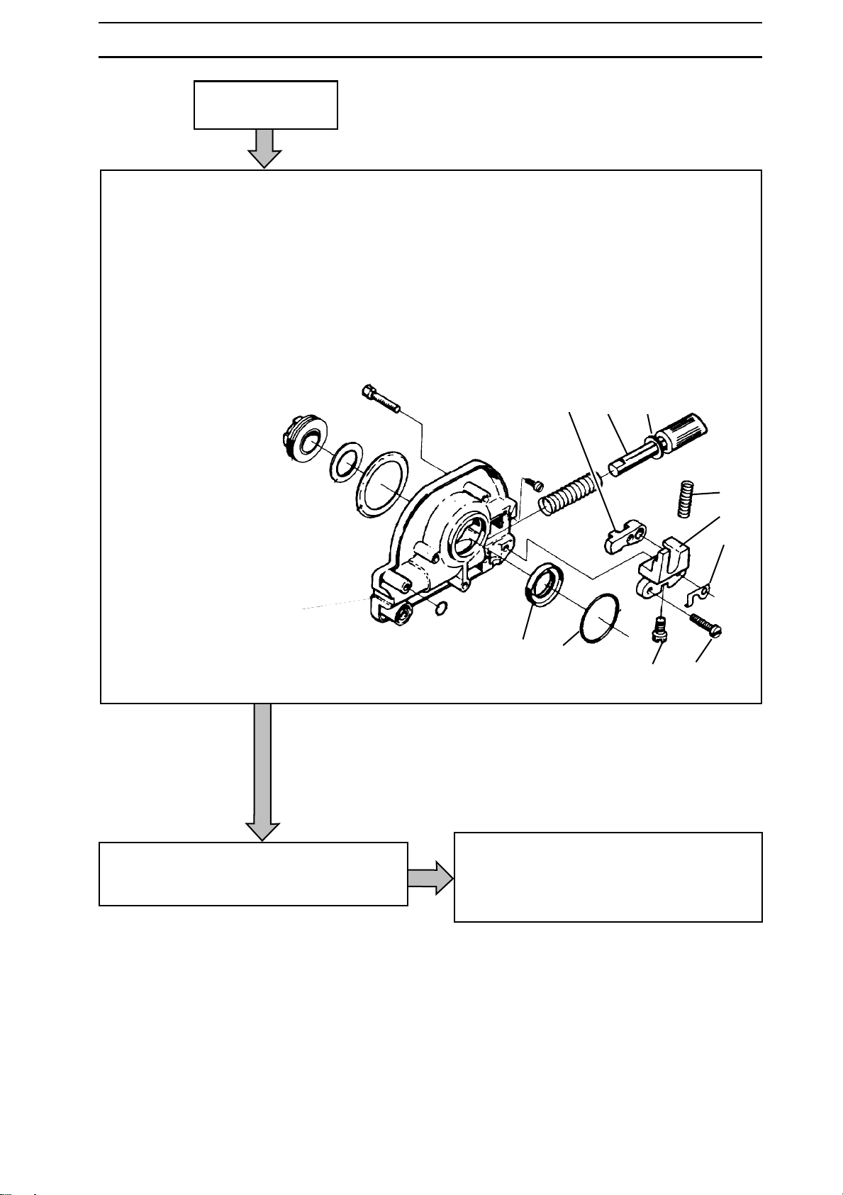
Saw 3120.
Fit the oil pump as follows:
1. Apply SAE 30 oil to all moving parts
2. Fit the seal (C).
3. Fit the pump piston (D) with spring.
Press in the piston and hold it in
position with a screwdriver from the
pump housing's inside in slot (E).
4. Fit screw (B) so that it is positioned
approx. one turn from the bottom.
NOTE! Left-hand thread
5. Fit lever arm (F).
6. Fit units (B-F-G) with spring (H) and
screw in position using screws (A) and
latch (J).
7. Remove the screwdriver.
8. Fit a new O-rings (K) and (L).
FDE
H
G
J
Fit the wire for manual oil supply.
CK
BA
See continuation on next page.
www.mymowerparts.com
English – 79
Page 80
For Husqvarna Parts Call 606-678-9623 or 606-561-4983
LUBRICATION SYSTEM
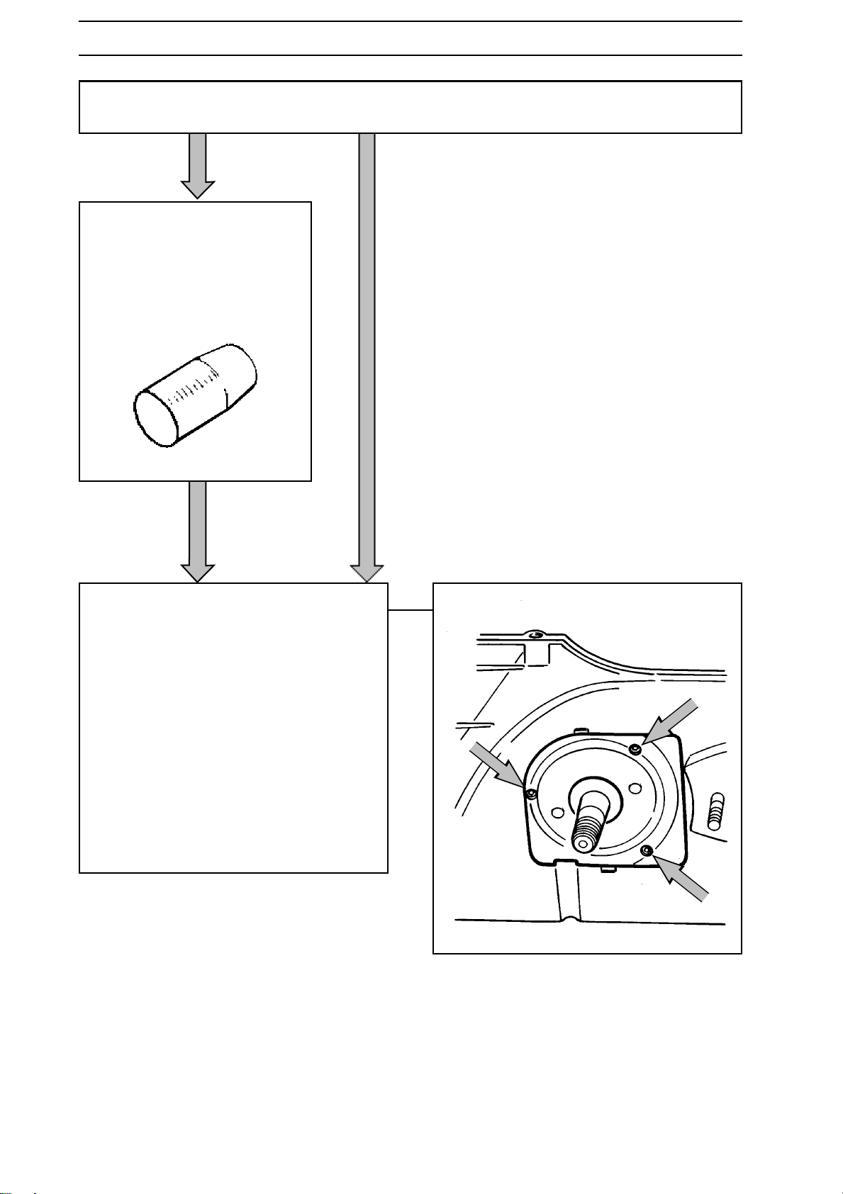
Saws 42, 61, 242, 246, 254, 257, 262, 268, 272, 281, 288, 394 and 3120.
Saws 61, 268, 272, 281 and 288
Use the tapered sleeve which
is placed on the shaft when
fitting the oil pump. Otherwise
the seals will be damaged.
1. Lubricate the pinion gear with grease.
2. Fit the oil pump on the saw by
tightening the three bolts.
3. If the tapered sleeve has been used,
remove it.
4. Fit the centrifugal clutch.
See page 69.
5. Fit the bar and chain.
6.
Adjust the oil pump for the correct oil flow.
See the operating instructions.
80 – English
www.mymowerparts.com
Page 81
For Husqvarna Parts Call 606-678-9623 or 606-561-4983
LUBRICATION SYSTEM
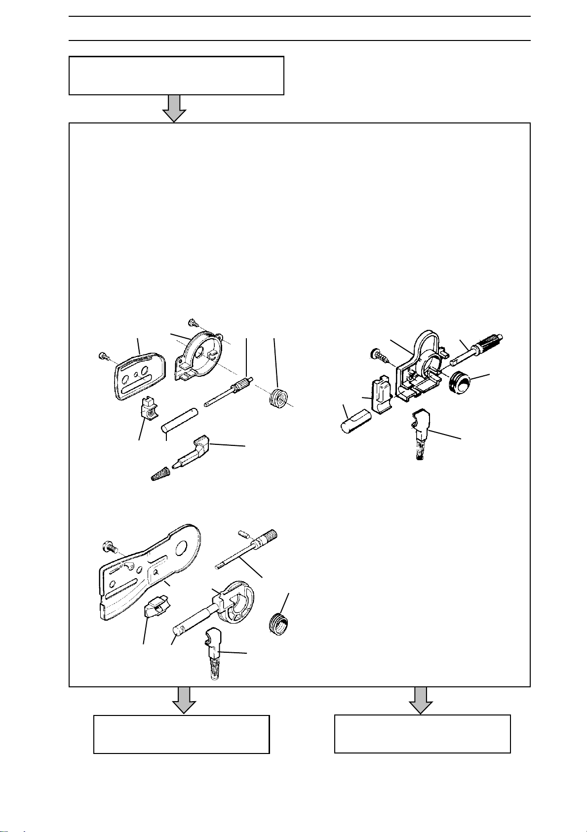
Saws 36, 40, 41, 45, 51 and 55.
Fit the oil pump as follows:
1. Apply SAE 30 oil to all moving parts.
2. Fit the worm gear (G) on the
crankshaft, if necessary
3. Fit the pump piston (F) in the pump
cylinder (B).
4. Fill the pump recess with grease.
5. Fit the unit in the pump housing (E).
Ensure the pump cylinder's cut-out
aligns in the pump housing.
6. Fit the lower seal (A) on the crankcase.
D E F G
CB A
36/41
A. Lower seal.
B. Pump cylinder.
C. Upper seal.
D. Chain guide plate.
E. Pump housing.
F. Pump piston.
G. Worm gear
E F
G
B C
A
40/45
D E F G
CB A
50/51
Saws 36, 40, 41 and 45, see
continuation on the next page.
Saws 51 and 55, see continuation
on the next page.
English – 81
www.mymowerparts.com
Page 82
For Husqvarna Parts Call 606-678-9623 or 606-561-4983
LUBRICATION SYSTEM
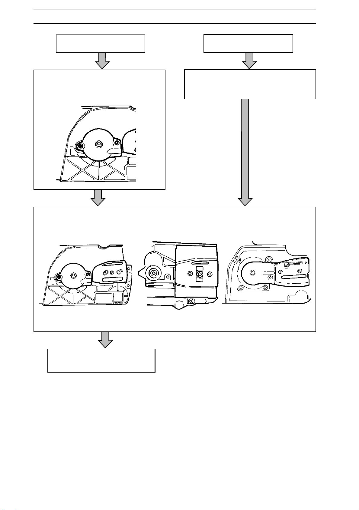
Saws 36, 40, 41 and 45.
Fit the oil pump in the crankcase, tighten
the two bolts and fit the upper seal.
Fit the chain guide plates according to
respective diagrams below.
Saws 51 and 55.
Fit the oil pump in the crankcase and fit
the upper seal.
82 – English
36/41 40/45 51/55
Fit the bar and chain.
www.mymowerparts.com
Page 83
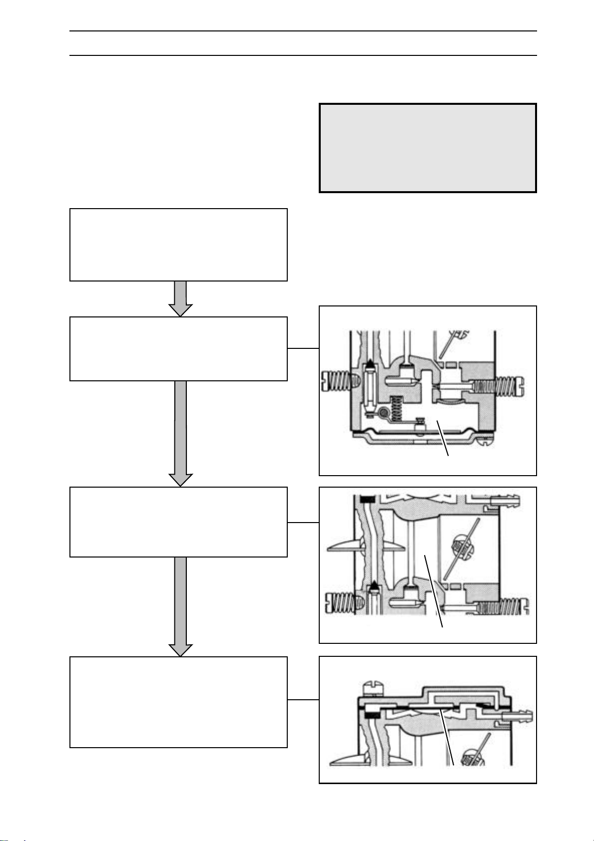
For Husqvarna Parts Call 606-678-9623 or 606-561-4983
CARBURETTOR
Description
The diagrams in this description do not
correspond with the carburettor fitted on
the chain saws. They serve only to show
the principles of design and operation.
Design
The carburettor consists of three sub-systems:
• Metering unit, A.
• Mixing venturi, B.
• Pump unit, C.
The metering unit (A) contains the jets and
fuel control functions. It is here the correct
amount of fuel for the given engine speed
and power is metered.
!
WARNING!
The fuel used in the chain saw poses
the following hazards:
1. The liquid and its vapours are
poisonous.
2. Can cause skin irritation.
3. Is highly inflammable.
The mixing venturi (B) houses the choke,
throttle valve and diffuser jets. Here air is
mixed with the fuel to give a fuel/air
mixture that can be ignited by the ignition
spark.
In the pump unit (C), fuel is pumped from the
fuel tank to the metering unit. One side of the
pump diaphragm is connected to the crankcase
and pulses in time with the pressure changes in
the crankcase. The other side of the diaphragm
pumps the fuel.
A
B
www.mymowerparts.com
C
English – 83
Page 84
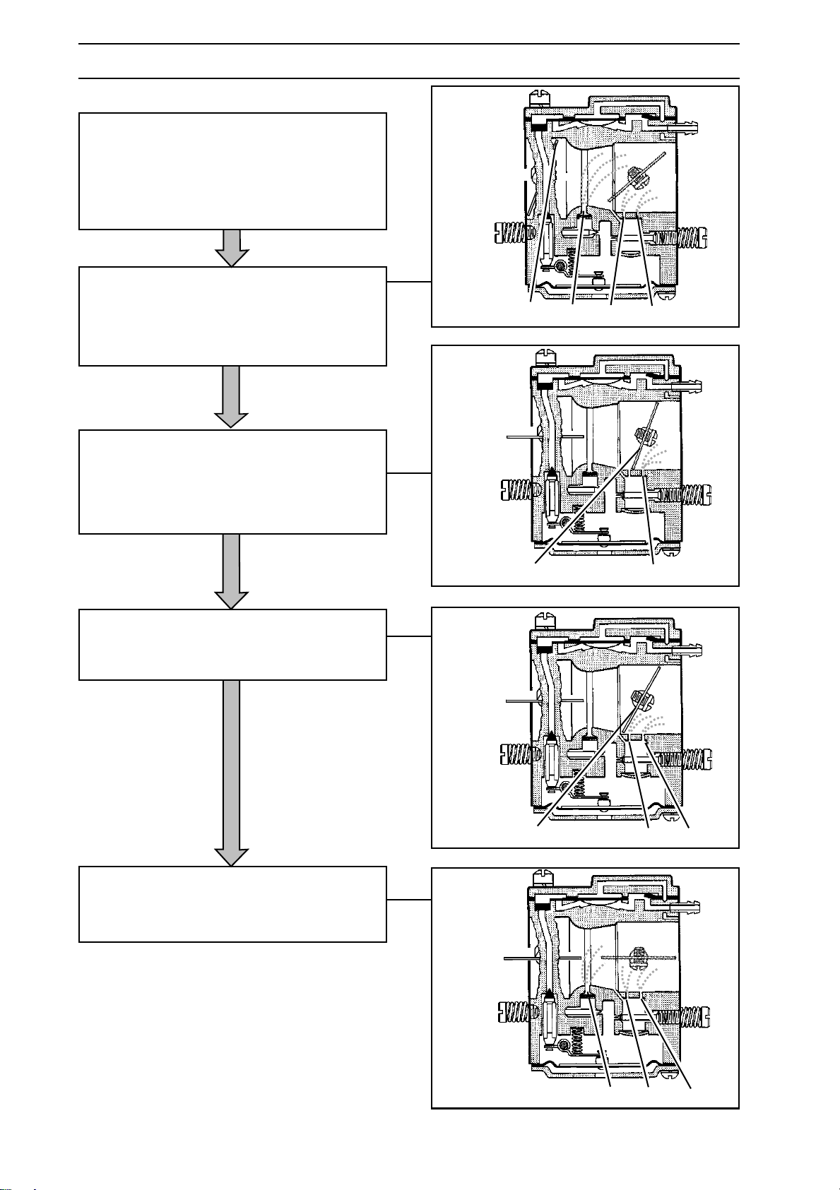
For Husqvarna Parts Call 606-678-9623 or 606-561-4983
CARBURETTOR
Operation
The carburettor operates differently in the
following modes:
• Cold start
• Idling
• Part throttle
• Full throttle
In the cold start mode the choke valve (D)
is fully closed. This increases the vacuum
in the carburettor and fuel is easier to suck
from all the diffuser jets (E, F and G). The
throttle valve (H) is partly open.
DEFG
In the idling mode (H) the throttle valve is
closed. Air is sucked in through an
aperture in the throttle valve and a small
amount of fuel is supplied through the
diffuser jet (G).
In the part throttle mode the throttle valve
(H) is partially open. Fuel is supplied
through the diffuser jets (F and G).
HG
HFG
In the full throttle mode both valves are
open and fuel is supplied through all three
diffuser jets (E, F and G).
84 – English
www.mymowerparts.com
EFG
Page 85
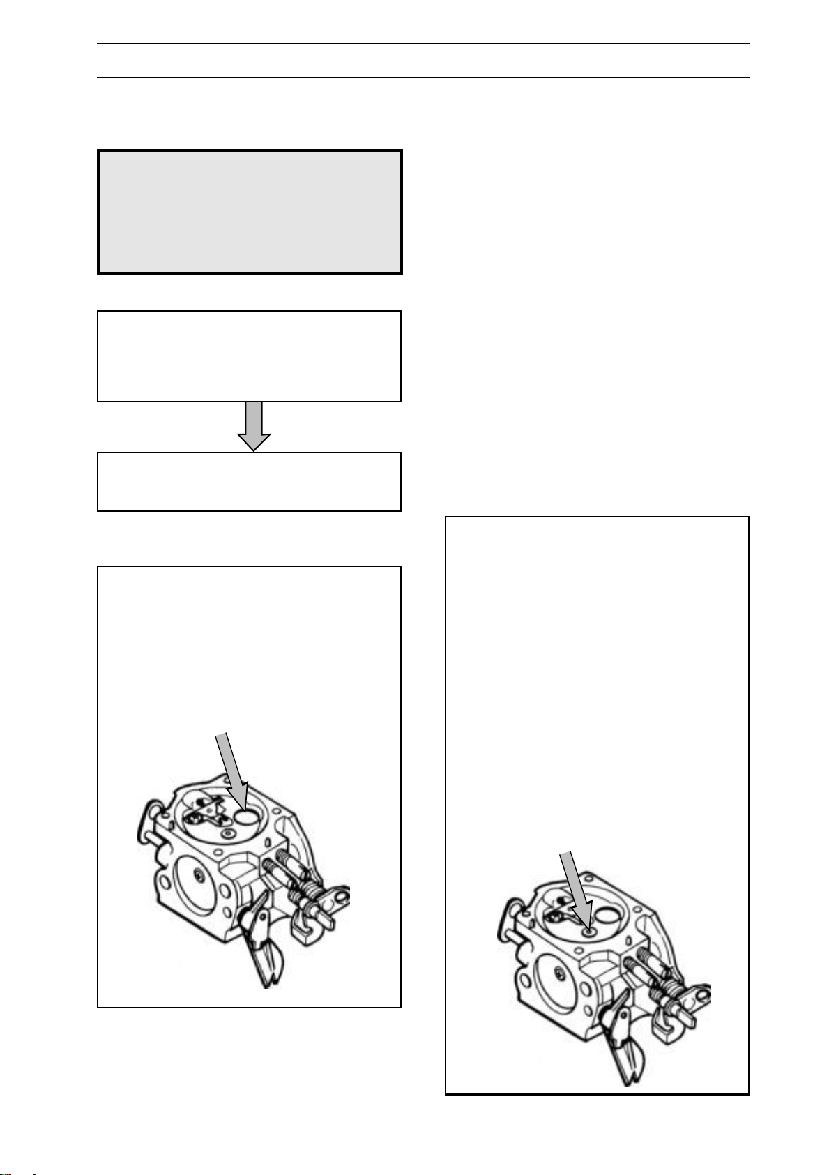
For Husqvarna Parts Call 606-678-9623 or 606-561-4983
CARBURETTOR
Dismantling
WARNING!
!
Dismantle all parts necessary and remove
the carburettor from the saw. On some
models the cylinder needs to be loosened
and lifted to be able to remove the
carburettor.
The fuel used in the chain saw
poses the following hazards:
1. The liquid and its vapours are
poisonous.
2. Can cause skin irritation.
3. Is highly inflammable.
See the carburettor in question on the next
four pages and the instructions below.
Plugs
When cleaning the carburettor the plugs
must be removed. Remove as follows:
1. Drill a hole in the plug.
2. Insert a screwdriver or punch in the hole
and prise up the plug.
”Semi fixed jet”/”fixed jet”
Some carburettors have an extra jet (semi
fixed jet). The jet is of brass and is located
in the metering unit and is used to give a
fuel supplement. On average 10% of the
fuel passes through the jet.
Below or next to the jet is a screen which
needs to be cleaned.
Dismantle the jet and/or screen in one of
the following ways:
1. Knock the unit into the venturi using a
punch and take the unit apart. (some
Tillotson models).
2. Dismantle the lock washer over the jet
and lift off the jet and screen.
www.mymowerparts.com
English – 85
Page 86
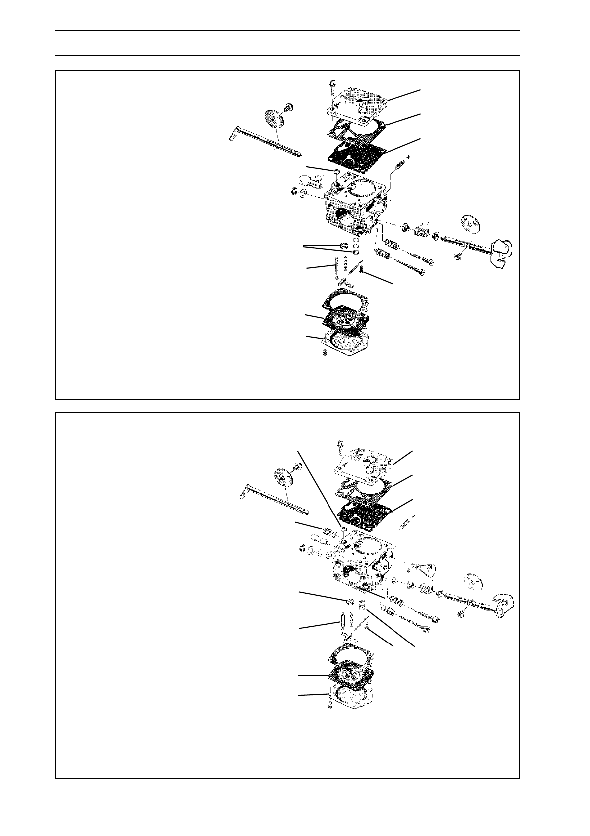
For Husqvarna Parts Call 606-678-9623 or 606-561-4983
CARBURETTOR
Tillotson HS 228 B
1. Remove the cover (A) over the metering
unit and carefully remove the control
diaphragm (B) with the gasket.
2. Undo the screw (H) and take out
the needle valve (C) with lever arm,
shaft and spring.
3. Remove the cover (E) over the pump unit
and carefully remove the gasket (F) and
the pump diaphragm (G).
4. Using a needle or the like carefully remove
the fuel screen (D).
5. Unscrew the high and low speed jet
screws.
6. Remove the plugs (J).
See page 85.
7. If necessary remove the throttle and choke
valves as well as the shafts, lever arms
and springs.
E
F
G
D
J
C
H
B
A
Tillotson HS 255 B
1. Remove the cover (A) over the metering
unit and carefully remove the control
diaphragm (B) with the gasket.
2. Undo the screw (H) and take out
the needle valve (C) with lever
arm, shaft and spring.
3. Remove the cover (E) over the pump unit
and carefully remove the gasket (F) and
the pump diaphragm (G).
4. Using a needle or the like carefully
remove the fuel screen (D).
5. Unscrew the high and low speed jet
screws.
6. Remove the plugs (J). See page 85.
7. If necessary remove the throttle and
choke valves as well as the shafts, lever
arms and springs.
D
I
J
C
B
A
E
F
G
H
H K
8. Remove the speed governor (I). (Only
272K, 268K and 272S).
9.
Remove the ”semi fixed jet” (K). See page 85.
86 – English
www.mymowerparts.com
Page 87
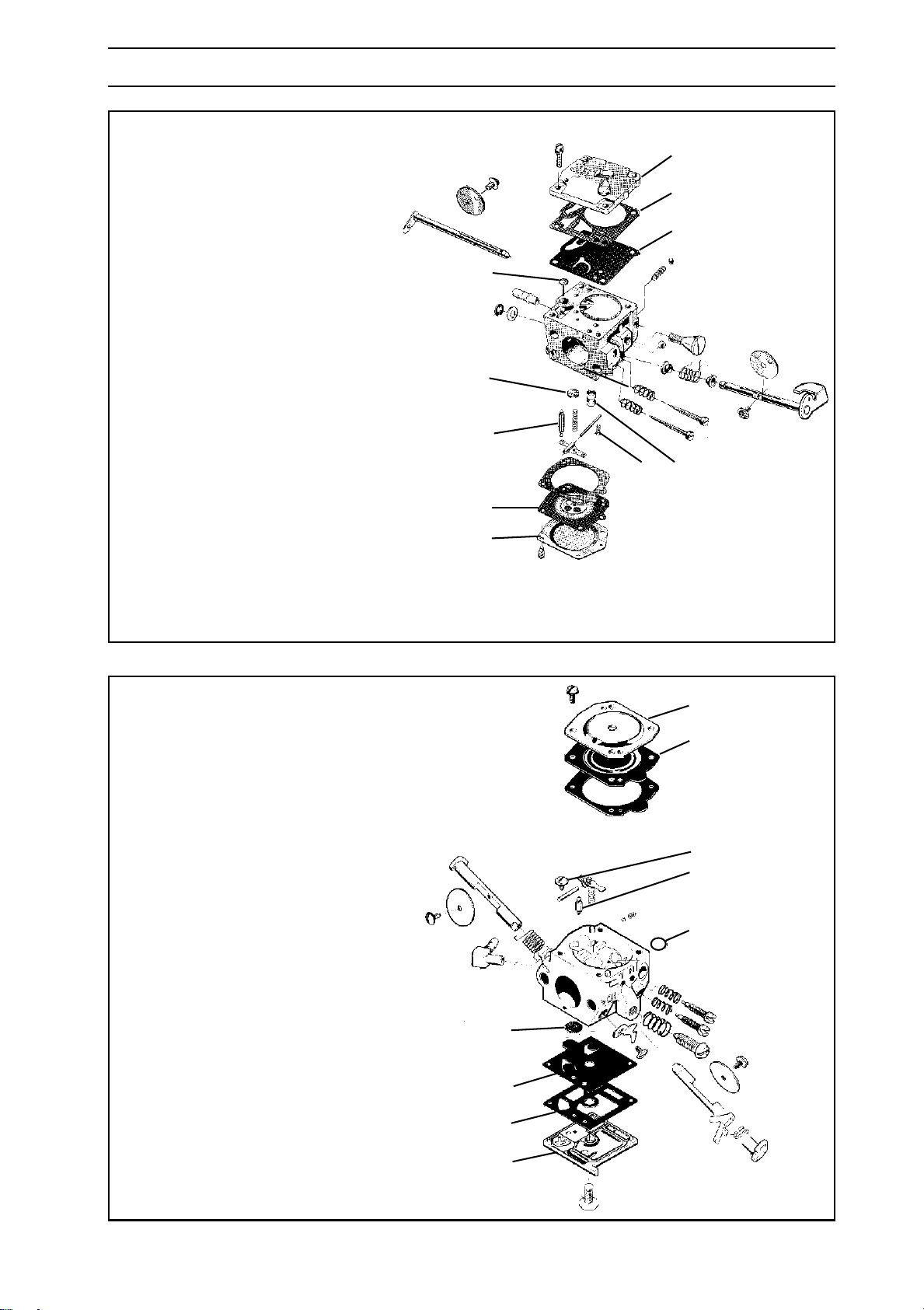
For Husqvarna Parts Call 606-678-9623 or 606-561-4983
CARBURETTOR
Tillotson HS 260 A
1. Remove the cover (A) over the metering
unit and carefully remove the control
diaphragm (B) with the gasket.
2. Undo the screw (H) and take out the
needle valve (C) with lever arm, shaft and
spring.
3. Remove the cover (E) over the pump unit
and carefully remove the gasket (F) and
the pump diaphragm (G).
4. Using a needle or the like carefully remove
the fuel screen (D).
5. Unscrew the high and low speed jet
screws.
6. Remove the plugs (J). See page 85.
7. If necessary remove the throttle and choke
valves as well as the shafts, lever arms
and springs.
E
F
G
D
J
H
C
H K
B
A
8.
Remove the ”semi fixed jet” (K). See page 85.
Walbro HDA and HD
1. Remove the cover (A) over the metering
unit and carefully remove the control
diaphragm (B) with the gasket.
2. Undo the screw (H) and take out the
needle valve (C) with lever arm, shaft and
spring.
3. Remove the cover (E) over the pump
unit and carefully remove the gasket (F)
and the pump diaphragm (G).
4. Using a needle or the like carefully remove
the fuel screen (D).
5. Unscrew the high and low speed jet
screws.
6. Remove the plug (J). See page 85.
7. If necessary remove the throttle and choke
valves as well as the shafts, lever arms and
springs.
A
B
H
C
J
D
G
F
E
www.mymowerparts.com
English – 87
Page 88
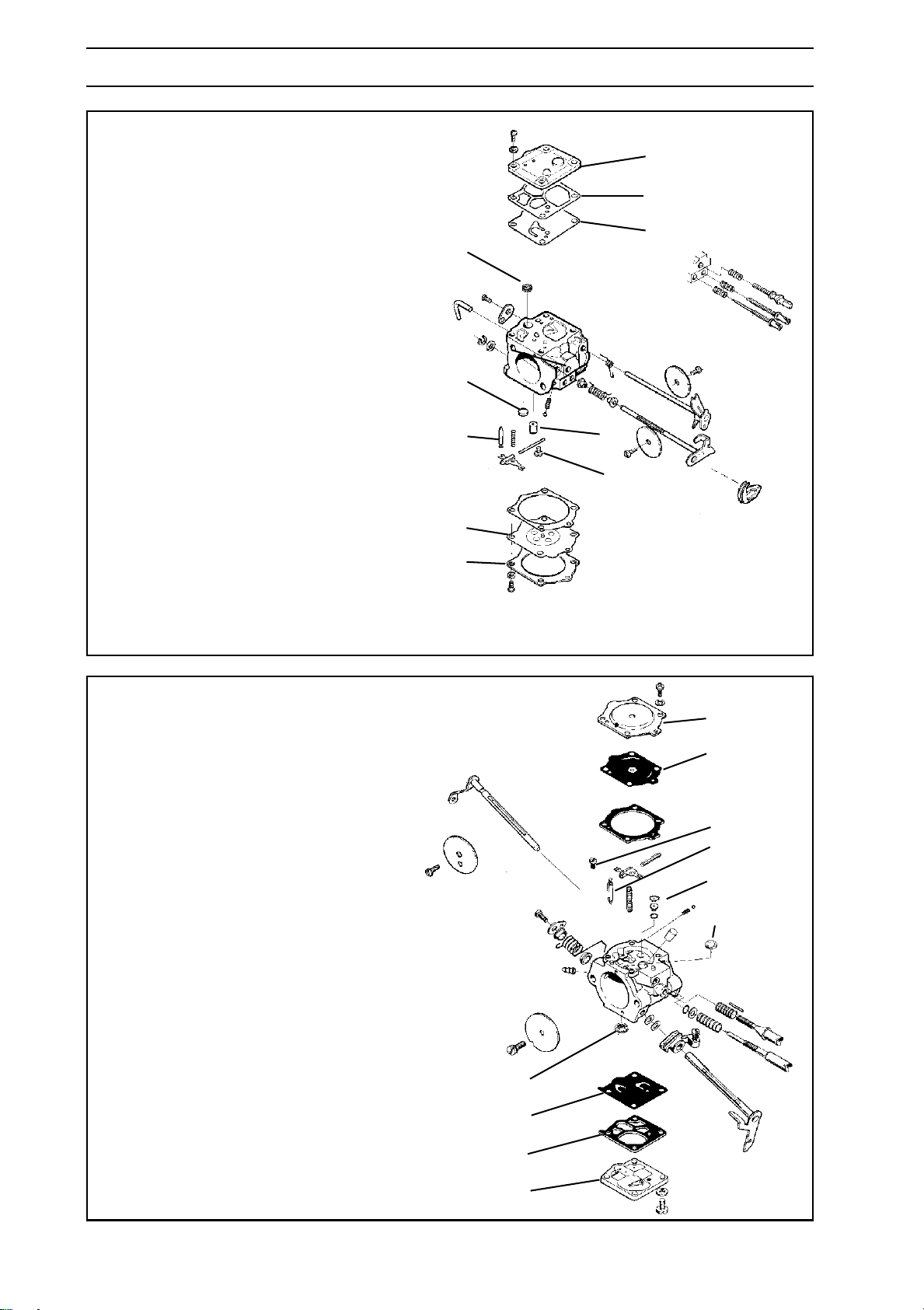
For Husqvarna Parts Call 606-678-9623 or 606-561-4983
CARBURETTOR
Walbro WJ
1. Remove the cover (A) over the metering
unit and carefully remove the control
diaphragm (B) with the gasket.
2. Undo the screw (H) and take out the
needle valve (C) with lever arm, shaft and
spring.
3. Remove the cover (E) over the pump unit
and carefully remove the gasket (F) and
the pump diaphragm (G).
4. Using a needle or the like carefully remove
the fuel screen (D).
5. Unscrew the high and low speed jet
screws.
6. Remove the plug (J). See page 85.
7. If necessary remove the throttle and choke
valves as well as the shafts, lever arms
and springs.
E
F
G
D
J
CK
H
B
A
8.
Remove the ”semi fixed jet” (K). See page 85.
Walbro WG
1. Remove the cover (A) over the metering
unit and carefully remove the control
diaphragm (B) with the gasket.
2. Undo the screw (H) and take out the
needle valve (C) with lever arm, shaft and
spring.
3. Remove the cover (E) over the pump unit
and carefully remove the gasket (F) and
the pump diaphragm (G).
4. Using a needle or the like carefully remove
the fuel screen (D).
5. Unscrew the low speed jet screws.
6. Remove the plugs (J). See page 85.
7. If necessary remove the throttle and choke
valves as well as the shafts, lever arms
and springs.
8.
Remove the ”semi fixed jet” (K). See page 85.
A
B
H
C
K
J
D
G
F
E
88 – English
www.mymowerparts.com
Page 89
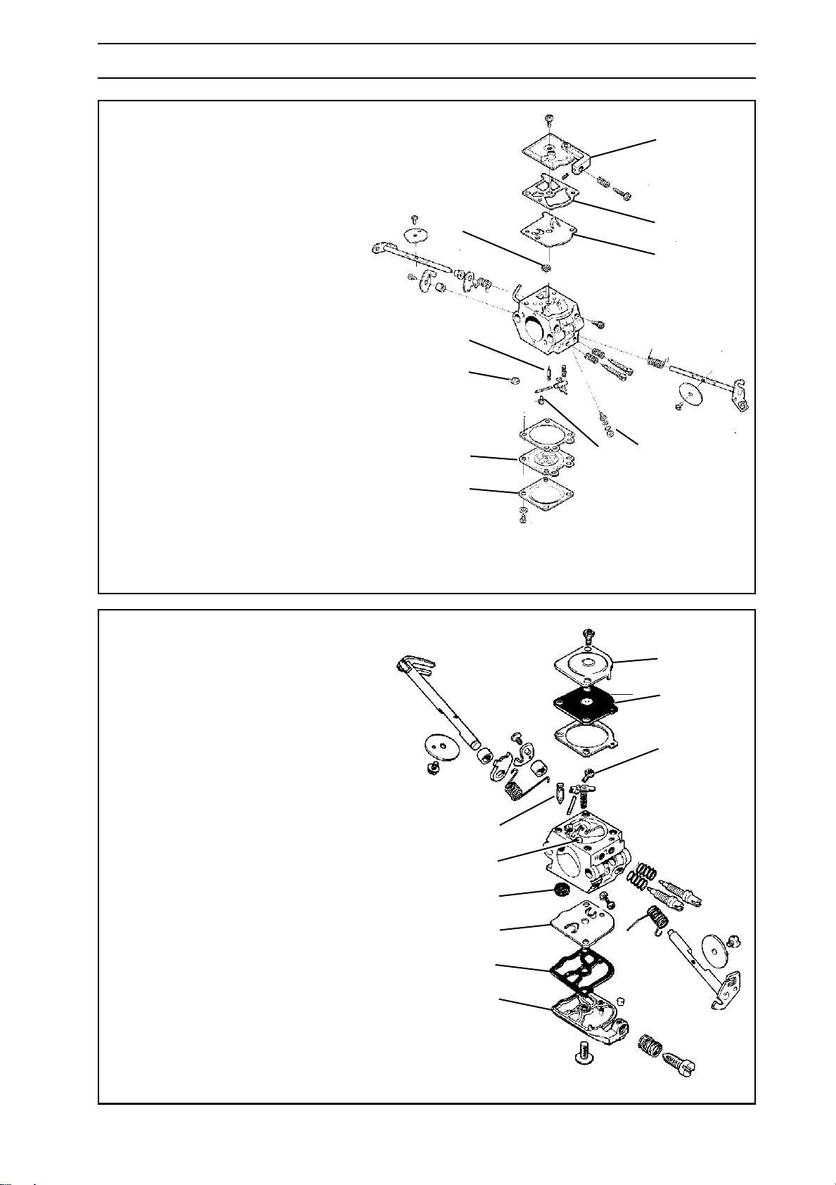
For Husqvarna Parts Call 606-678-9623 or 606-561-4983
CARBURETTOR
Walbro WT
1. Remove the cover (A) over the metering
unit and carefully remove the control
diaphragm (B) with the gasket.
E
2. Undo the screw (H) and take out the
needle valve (C) with lever arm, shaft
and spring.
3. Remove the cover (E) over the pump
unit and carefully remove the gasket (F)
and the pump diaphragm (G).
4. Using a needle or the like carefully remove
the fuel screen (D).
5. Unscrew the high and low speed jet
screws.
6. Remove the plug (J). See page 85.
7. If necessary remove the throttle and choke
valves as well as the shafts, lever arms
and springs.
8.
Remove the ”semi fixed jet” with diffuser
jet (K). See page 85.
D
C
J
BH K
A
F
G
ZAMA C1Q-EL1
1. Remove the cover (A) over the metering
unit and carefully remove the control
diaphragm (B) with the gasket.
2. Undo the screw (H) and take out the
needle valve (C) with lever arm, shaft and
spring.
3. Remove the cover (E) over the pump unit
and carefully remove the gasket (F) and
the pump diaphragm (G).
4. Using a needle or the like carefully remove
the fuel screen (D).
5. Unscrew the high and low speed jet
screws.
6. If necessary remove the throttle and
choke valves as well as the shafts, lever
arms and springs.
A
B
H
C
K
D
G
F
E
www.mymowerparts.com
English – 89
Page 90
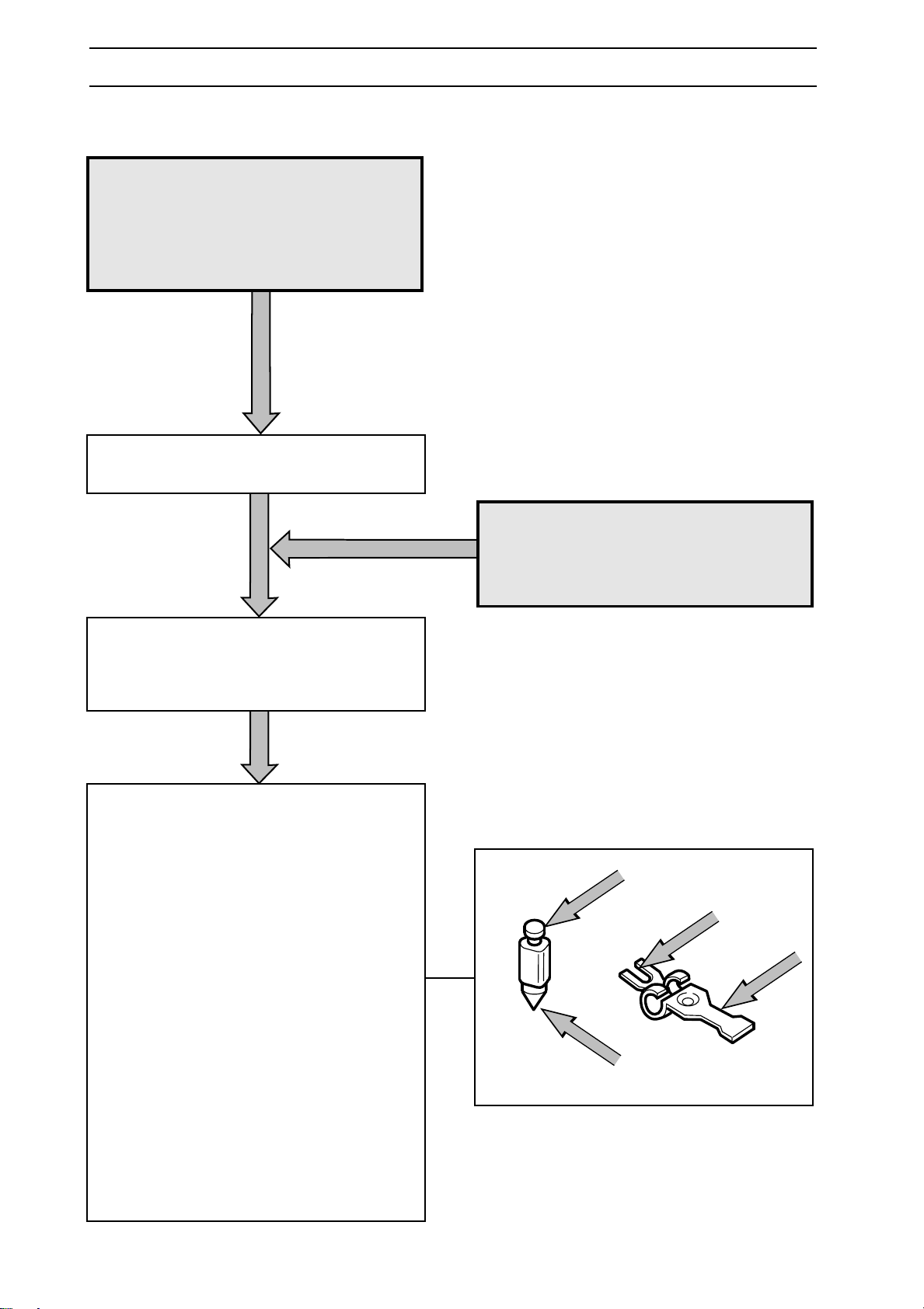
For Husqvarna Parts Call 606-678-9623 or 606-561-4983
CARBURETTOR
Cleaning and Inspection
WARNING!
!
Clean all components in petrol. Wear
gloves or skin protection cream.
The fuel used in the chain saw
poses the following hazards:
1. The liquid and its vapours are
poisonous.
2. Can cause skin irritation.
3. Is highly inflammable.
Use compressed air to dry the petrol on the
components. Direct the air through all
channels in the carburettor housing and
ensure that they are not blocked.
Refer to the carburettor diagram in
question on the previous pages and check
the following:
1. That the gasket and pump and control
diaphragms are undamaged.
2. That there is no play on the throttle and
choke valve shafts.
!
WARNING!
Never direct the compressed air
jet towards the body. Air can be
forced into the blood stream and
can cause fatality.
3. That the needle valve and its lever are
not worn.
4. That the fuel screen is undamaged
5. That the tips of the high and low speed
jet screws are not damaged.
6. On Tillotson HS 255 B, that the speed
governor (I) is clean.
7. That the air intake manifold is not cracked.
90 – English
www.mymowerparts.com
Page 91
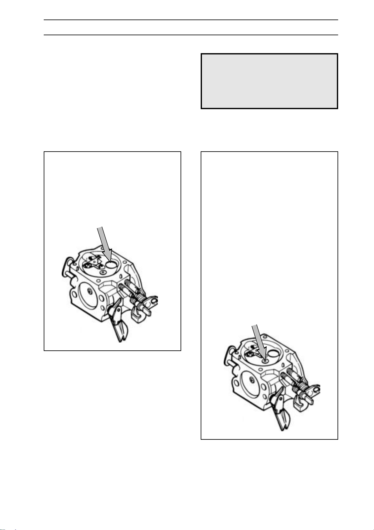
For Husqvarna Parts Call 606-678-9623 or 606-561-4983
CARBURETTOR
Assembly
Refer to the carburettor in question on the
next eight pages. A pressure test, see
page 100, should be carried out after
assembling and before the carburettor is
refitted to the saw.
Plugs
When cleaning the carburettor the plugs
must be removed.
Reassemble as follows:
1. Place the plug in the hole with the
convex side facing upwards.
2. Expand the plug by using a punch on
the top side.
WARNING!
!
”Semi fixed jet”/”fixed jet”
Some carburettors have an extra jet (semi
fixed jet). The jet is of brass and is located
in the metering unit and is used to give a
fuel supplement. On average 10% of the
fuel passes through the jet.
Below or next to the jet is a screen which
needs to be cleaned.
Reassemble the jet and/or screen in one
of the following ways:
The fuel used in the chain saw
poses the following hazards:
1. The fluid and its vapours are
poisonous.
2. Can cause skin irritation.
3. Is highly inflammable.
1. Put together the unit and fit it in the
carburettor by means of a punch (Some
Tillotson models).
2. Fit the jet with screen and lock washer.
www.mymowerparts.com
English – 91
Page 92
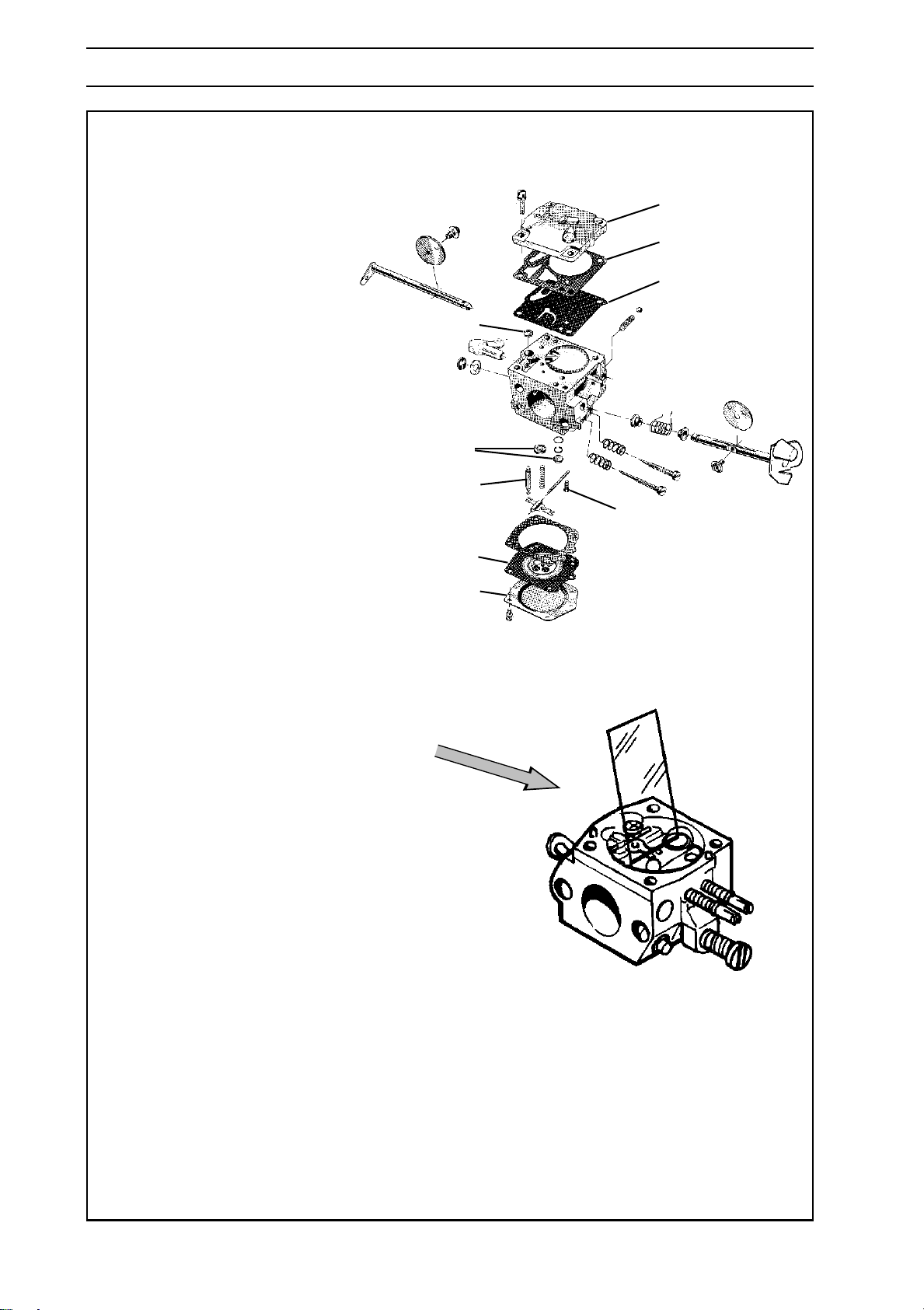
For Husqvarna Parts Call 606-678-9623 or 606-561-4983
CARBURETTOR
Tillotson HS 228 B
Maintain a high level of cleanliness when
reassembling the carburettor. Even small
particles of dirt can cause operating
problems.
1. If the throttle and choke valves, shafts,
lever arms and springs have been
dismantled these must be reassembled.
Lubricate the shaft bearings using a
light oil.
2. Fit the plugs (J). See page 91.
3. Fit the high and low jet screws and
springs. NOTE! Do not tighten the
screws against the seats. This can
damage the seats and needle tips.
4. Fit the fuel screen (D) by using the
handle of a small screwdriver.
5. Fit the pump diaphragm (G), gasket
(F) and cover (E) on the pump unit.
E
F
G
D
J
C
H
B
A
6. Fit the needle valve (C) with lever arm,
shaft and spring and tighten screw (H).
7. Check, using or a ruler or the like, that
the lever arm is level with the chamber
floor. See the figure to the lower right.
The lever arm can be bent if necessary
to achieve the correct settings.
8. Fit the control diaphragm (B) with
gasket and cover (A) on the metering
unit.
9. Carry out a pressure test.
See page 100
.
92 – English
www.mymowerparts.com
Page 93
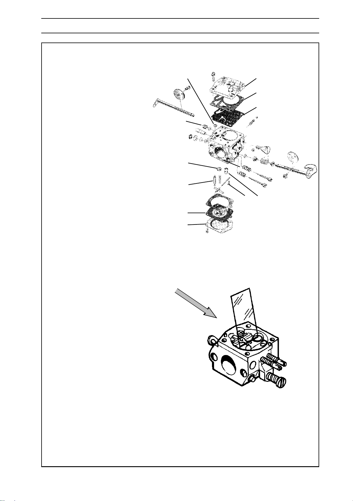
For Husqvarna Parts Call 606-678-9623 or 606-561-4983
CARBURETTOR
Tillotson HS 255 B
Maintain a high level of cleanliness when
reassembling the carburettor. Even small
particles of dirt can cause operating problems.
1. If the throttle and choke valves, shafts,
lever arms and springs have been
dismantled these must be reassembled.
Lubricate the shaft bearings using a light
oil.
2. Fit the plugs (J). See page 91.
3. Fit the ”semi fixed jet” (K). See page 91.
4. Fit the high and low jet screws and springs.
NOTE! Do not tighten the screws against
the seats. This can damage the seats and
needle tips.
5. Fit the fuel screen (D) by using the handle
of a small screwdriver.
6. Fit the pump diaphragm (G), gasket
(F) and cover (E) on the pump unit.
D
I
J
C
B
A
E
F
G
H
H K
7. Fit the needle valve (C) with lever arm,
shaft and spring and tighten screw (H).
8. Check, using or a ruler or the like, that the
lever arm is level with the chamber floor.
See the figure to the lower right. The lever
arm can be bent if necessary to achieve
the correct settings.
9. Fit the speed governor (I). Lock with
Loctite or locking lacquer. (Only applies to
272K, 268K and 272S).
10. Fit the control diaphragm (B) with gasket
and cover (A) on the metering unit.
11. Carry out a pressure test.
See page 100.
www.mymowerparts.com
English – 93
Page 94
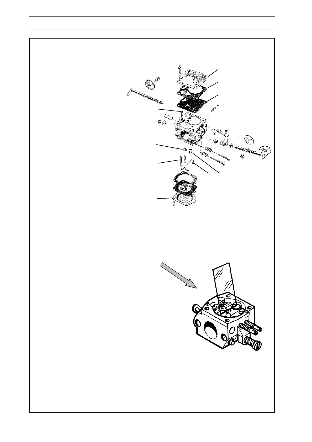
For Husqvarna Parts Call 606-678-9623 or 606-561-4983
CARBURETTOR
Tillotson HS 260 A
Maintain a high level of cleanliness when
reassembling the carburettor. Even small
particles of dirt can cause operating
problems.
1. If the throttle and choke valves, shafts,
lever arms and springs have been
dismantled these must be reassembled.
Lubricate the shaft bearings using a light
oil.
2. Fit the plugs (J). See page 91.
3. Fit the ”semi fixed jet” (K). See page 91.
4. Fit the high and low jet screws and
springs. NOTE! Do not tighten the screws
against the seats. This can damage the
seats and needle tips.
5. Fit the fuel screen (D) by using the handle
of a small screwdriver.
6. Fit the pump diaphragm (G), gasket
(F) and cover (E) on the pump unit.
E
F
G
D
J
H
C
H K
B
A
7. Fit the needle valve (C) with lever arm,
shaft and spring and tighten screw (H).
8. Check, using or a ruler or the like, that the
lever arm is level with the chamber floor.
See the figure to the lower right. The lever
arm can be bent if necessary to achieve
the correct settings.
9. Fit the control diaphragm (B) with gasket
and cover (A) on the metering unit.
10. Carry out a pressure test. See page 100.
94 – English
www.mymowerparts.com
Page 95
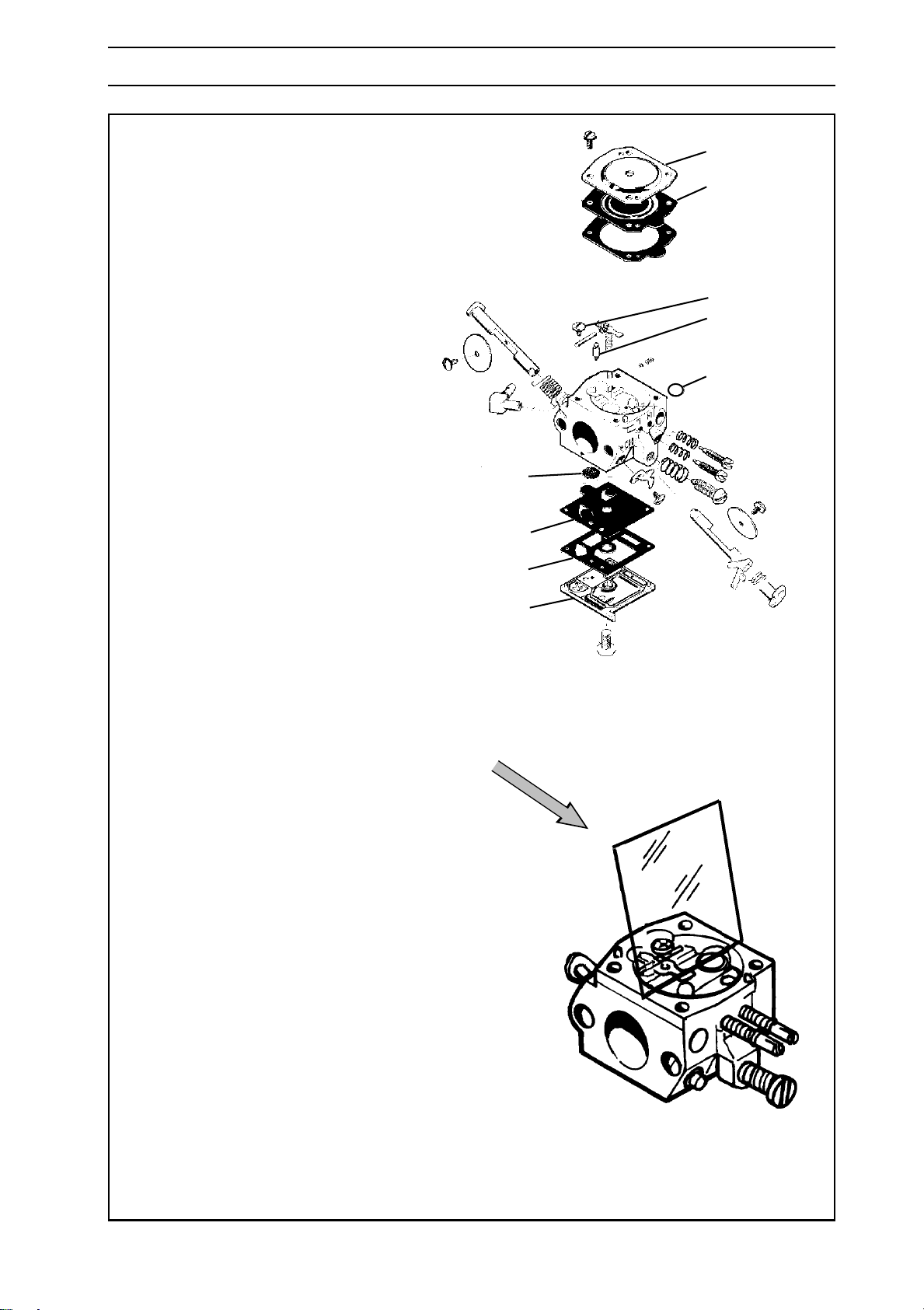
For Husqvarna Parts Call 606-678-9623 or 606-561-4983
CARBURETTOR
Walbro HDA och HD
Maintain a high level of cleanliness when
reassembling the carburettor. Even small
particles of dirt can cause operating problems.
1. If the throttle and choke valves, shafts,
lever arms and springs have been
dismantled these must be reassembled.
Lubricate the shaft bearings using a
light oil.
2. Fit the plugs (J). See page 91.
3. Fit the high and low jet screws and springs.
NOTE! Do not tighten the screws against
the seats. This can damage the seats and
needle tips.
4. Fit the fuel screen (D) by using the handle
of a small screwdriver.
A
B
H
C
J
D
G
F
5. Fit the pump diaphragm (G), gasket
(F) and cover (E) on the pump unit.
6. Fit the needle valve (C) with lever arm,
shaft and spring and tighten screw (H).
7. Check, using or a ruler or the like, that the
lever arm is level with the chamber floor.
See the figure to the lower right. The lever
arm can be bent if necessary to achieve
the correct settings.
8. Fit the control diaphragm (B) with gasket
and cover (A) on the metering unit.
9. Carry out a pressure test. See page 100
.
E
www.mymowerparts.com
English – 95
Page 96
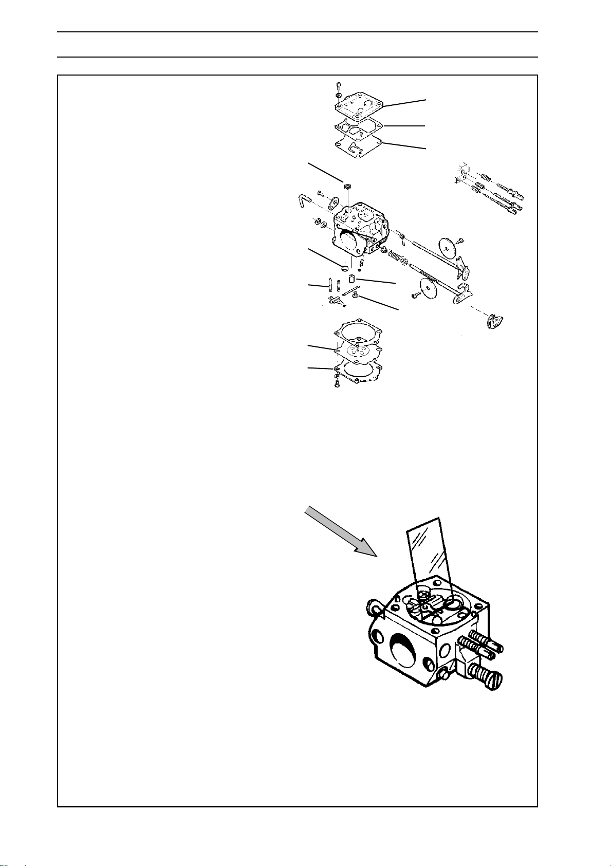
For Husqvarna Parts Call 606-678-9623 or 606-561-4983
CARBURETTOR
Walbro WJ
Maintain a high level of cleanliness when
reassembling the carburettor. Even small
particles of dirt can cause operating problems.
1. If the throttle and choke valves, shafts, lever
arms and springs have been dismantled
these must be reassembled. Lubricate the
shaft bearings using a light oil.
2. Fit the plugs (J). See page 91.
3. Fit the ”semi fixed jet” (K). See page 91.
4. Fit the high and low jet screws and springs.
NOTE! Do not tighten the screws against
the seats. This can damage the seats and
needle tips.
5. Fit the fuel screen (D) by using the handle
of a small screwdriver.
E
F
G
D
J
CK
H
B
A
6. Fit the pump diaphragm (G), gasket
(F) and cover (E) on the pump unit.
7. Fit the needle valve (C) with lever arm, shaft
and spring and tighten screw (H).
8. Check, using or a ruler or the like, that the
lever arm is level with the chamber floor.
See the figure to the lower right. The lever
arm can be bent if necessary to achieve the
correct settings.
9. Fit the control diaphragm (B) with gasket
and cover (A) on the metering unit.
10. Carry out a pressure test. See page 100.
96 – English
www.mymowerparts.com
Page 97
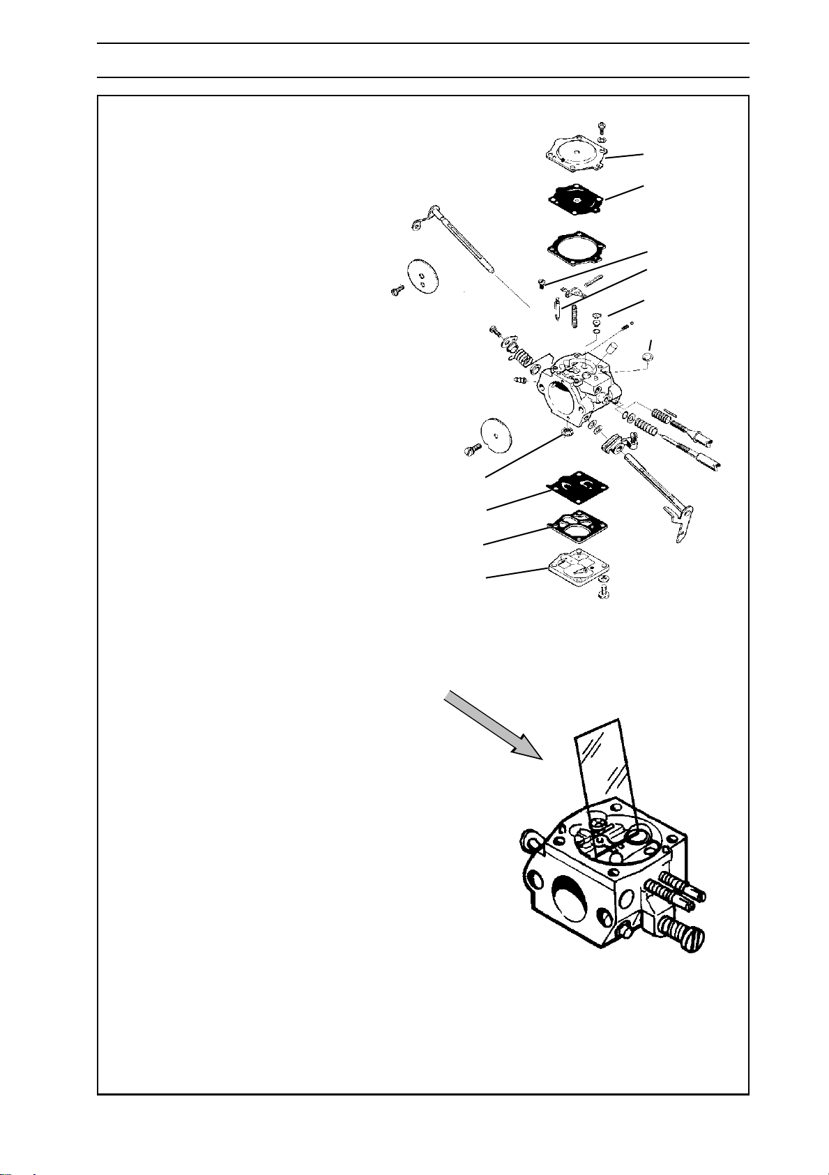
For Husqvarna Parts Call 606-678-9623 or 606-561-4983
CARBURETTOR
Walbro WG
A
Maintain a high level of cleanliness when
reassembling the carburettor. Even small
particles of dirt can cause operating problems.
1. If the throttle and choke valves, shafts,
lever arms and springs have been
dismantled these must be reassembled.
Lubricate the shaft bearings using a light oil.
2. Fit the plugs (J). See page 91.
3. Fit the ”fixed jet” (K). See page 91.
4. Fit the high and low jet screws and springs.
NOTE! Do not tighten the screws against
the seats. This can damage the seats and
needle tips.
5. Fit the fuel screen (D) by using the handle
of a small screwdriver.
6. Fit the pump diaphragm (G), gasket
(F) and cover (E) on the pump unit.
7. Fit the needle valve (C) with lever arm, shaft
and spring and tighten screw (H).
B
H
C
K
J
D
G
F
E
8. Check, using or a ruler or the like, that the
lever arm is level with the chamber floor.
See the figure to the lower right. The lever
arm can be bent if necessary to achieve the
correct settings.
9. Fit the control diaphragm (B) with gasket
and cover (A) on the metering unit.
10.
Carry out a pressure test. See page 100.
www.mymowerparts.com
English – 97
Page 98
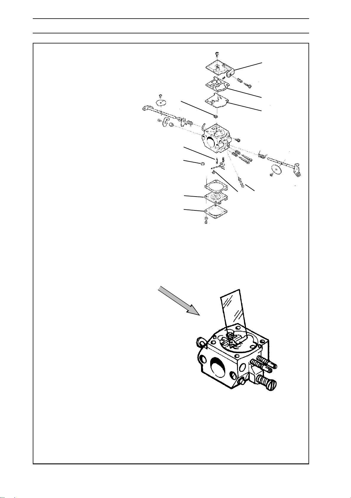
For Husqvarna Parts Call 606-678-9623 or 606-561-4983
CARBURETTOR
Walbro WT
E
Maintain a high level of cleanliness when
reassembling the carburettor. Even small
particles of dirt can cause operating
problems.
1. If the throttle and choke valves, shafts,
lever arms and springs have been
dismantled these must be reassembled.
Lubricate the shaft bearings using a light oil.
2. Fit the plugs (J). See page 91.
3. Fit the ”semi fixed jet” (K). See page 91.
D
C
J
F
G
4. Fit the high and low jet screws and springs.
NOTE! Do not tighten the screws against
the seats. This can damage the seats and
needle tips.
5. Fit the fuel screen (D) by using the handle of
a small screwdriver.
6. Fit the pump diaphragm (G), gasket
(F) and cover (E) on the pump unit.
7. Fit the needle valve (C) with lever arm, shaft
and spring and tighten screw (H).
8. Check, using or a ruler or the like, that the
lever arm is level with the chamber floor.
See the figure to the lower right. The lever
arm can be bent if necessary to achieve the
correct settings.
9. Fit the control diaphragm (B) with gasket
and cover (A) on the metering unit.
Carry out a pressure test. See page 100.
10.
BH K
A
98 – English
www.mymowerparts.com
Page 99
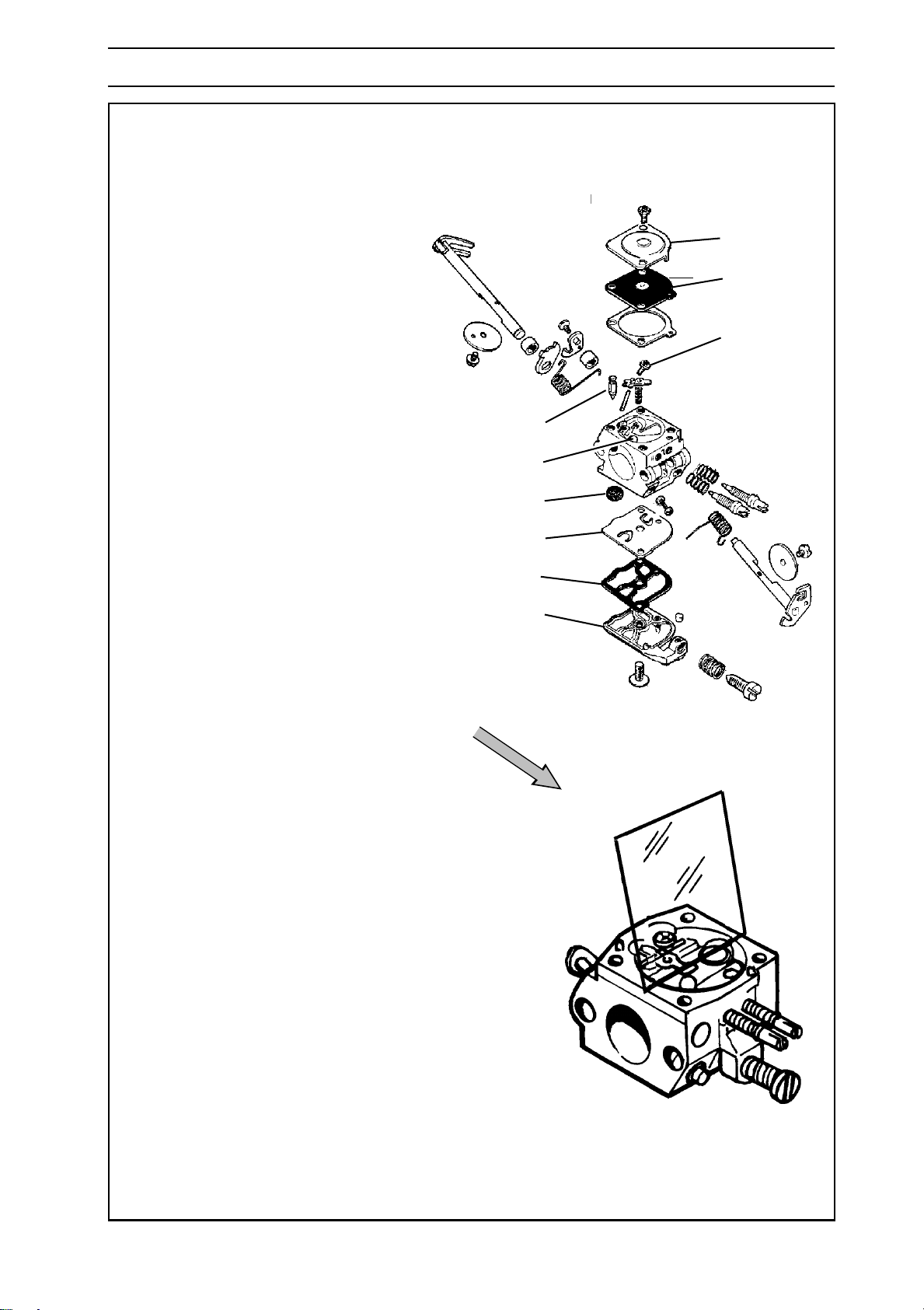
For Husqvarna Parts Call 606-678-9623 or 606-561-4983
CARBURETTOR
ZAMA C1Q-EL1
Maintain a high level of cleanliness when
reassembling the carburettor. Even small
particles of dirt can cause operating
problems.
1. If the throttle and choke valves, shafts,
lever arms and springs have been
dismantled these must be reassembled.
Lubricate the shaft bearings using a light
oil.
2. Fit the high and low jet screws and springs.
NOTE! Do not tighten the screws against
the seats. This can damage the seats and
needle tips.
C
K
A
B
H
3. Fit the fuel screen (D) by using the handle
of a small screwdriver.
4. Fit the pump diaphragm (G), gasket
(F) and cover (E) on the pump unit.
5. Fit the needle valve (C) with lever arm,
shaft and spring and tighten screw (H).
6. Check, using or a ruler or the like, that the
lever arm is level with the chamber floor.
See the figure to the lower right. The lever
arm can be bent if necessary to achieve
the correct settings.
7. Fit the control diaphragm (B) with gasket
and cover (A) on the metering unit.
8.
Carry out a pressure test. See page 100.
D
G
F
E
www.mymowerparts.com
English – 99
Page 100
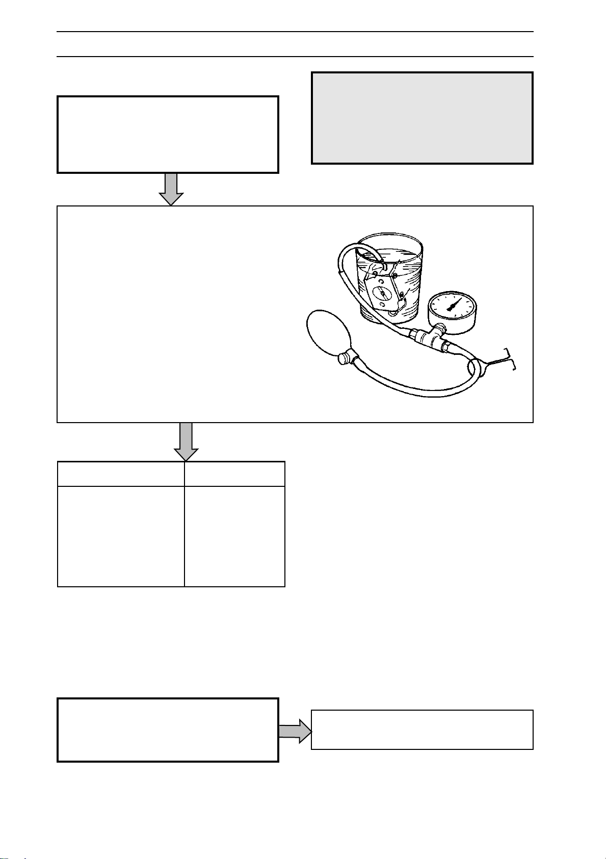
For Husqvarna Parts Call 606-678-9623 or 606-561-4983
CARBURETTOR
Pressure testing
WARNING!
The fuel used in the chain saw
poses the following hazards:
1. The liquid and its vapours are
poisonous.
2. Can cause skin irritation.
3. Is highly inflammable.
Pressure testing should be carried out with the
carburettor fully assembled. Testing should
always be carried out after the carburettor has
been repaired, but a test can also be made for
trouble shooting before dismantling.
Make the test as follows:
1. Set the high and low speed jet screws
one turn open from the bottom.
2. Connect pressure tester 502 50 38-01
to the carburettor’s fuel intake.
!
3. Lower the carburettor into a beaker of
water.
4. Pump up the pressure to 50 kPa (0.5
bar) and clamp the pump tube with the
spring clip.
5. There should be no leakage. If a
leakage occurs refer to the table below.
Leakage on Fault with
Diffuser jets Needle valve
Leakage on the Pump diaphragm
pulse tube
Ventilation hole Control diaphragm
above the metering unit
Refitting onto chain saw
Fit the carburettor to the chain saw and
refit any other parts removed.
For tightening torques, see the ”Service
data” for the saw in question.
100 – English
www.mymowerparts.com
Carburettor adjustment. See the operating
instructions for the saw in question.
 Loading...