

Page 1

For Husqvarna Parts Call 606-678-9623 or 606-561-4983
Assembly & Set-Up
Instructions
Rider 15 Pro
Rider 16 H
www.mymowerparts.com
Page 2

For Husqvarna Parts Call 606-678-9623 or 606-561-4983
HARDW
ARE LIST
QTY. DESCRIPTION PART NO. NOTE
1 Draw Ring (Hitch) 506 88 99-01
2 Bolt (Hitch) 725 24 93-71
2 Nuts & Bolts (battery terminal) Pre-packed in plastic bag.
1 Pack of Filler Plugs (battery) Pre-packed in plastic bag (6 per/bag).
1 Warranty Card
1 Owners Manual
2 Key 506 50 46-01 Rear wheels.
2 Retaining ring 735 31 21-00
2 Spacer 506 59 62-02 L= 18 mm (.7 inches) for hydrostatic
2 Washer 506 50 48-03
For hydrostatic.
2 Washer 506 50 48-01
2 Retaining ring 735 31 22-00
2 Washer 506 50 48-05 Front wheels.
2 Hub cap 506 92 30-01 Rear wheels.
2 Hub cap 506 95 58-01 Front wheels.
2 Ignition Key 506 91 74-01
Front wheels.
2
www.mymowerparts.com
Page 3

For Husqvarna Parts Call 606-678-9623 or 606-561-4983
SERVICE JOURNAL
Pre-delivery setup
Work done
1. Top up battery with acid and recharge for four hours.
2. Fit steering wheel, seat and any optional equipment.
3. Fit cutting unit.
4. Adjust cutting unit:
Adjust lift springs. Effective weight of cutting unit should
12–15 kg ( 26-33 lbs).
be
Adjust cutting unit so that rear edge is about 2–4 mm
(.08 -.16 in)
Adjust cutting unit height setting so that cutting height limit
is 5 mm ( .2 in) above the frame of the unit at the lowest
cutting
5. Check that engine has correct amount of oil.
6. Check and adjust tire pressure to 60 kPa (9 PSI).
7. Connect battery.
higher than front edge.
height.
Date / Signature
8. Fill with fuel and start engine.
9. Check that machine does not move in neutral.
10. Check:
Forward drive.
Reverse drive.
Operation of blades.
Seat safety switch.
Lift lever safety switch.
Parking brake safety switch.
11. Check engine revs 3,000–3,100 rpm.
12. Tell customer about:
Need and benefits of following the service schedule.
Need and benefits of having machine serviced every 300
hours.
Servicing and the influence of this journal on the secondhand value of the machine.
Pre-delivery service carried out.
No outstanding problems.
Certified:
Range of applications for BioClip.
13. Complete proof of sale, etc.
www.mymowerparts.com
3
Page 4
For Husqvarna Parts Call 606-678-9623 or 606-561-4983
MAINTENANCE
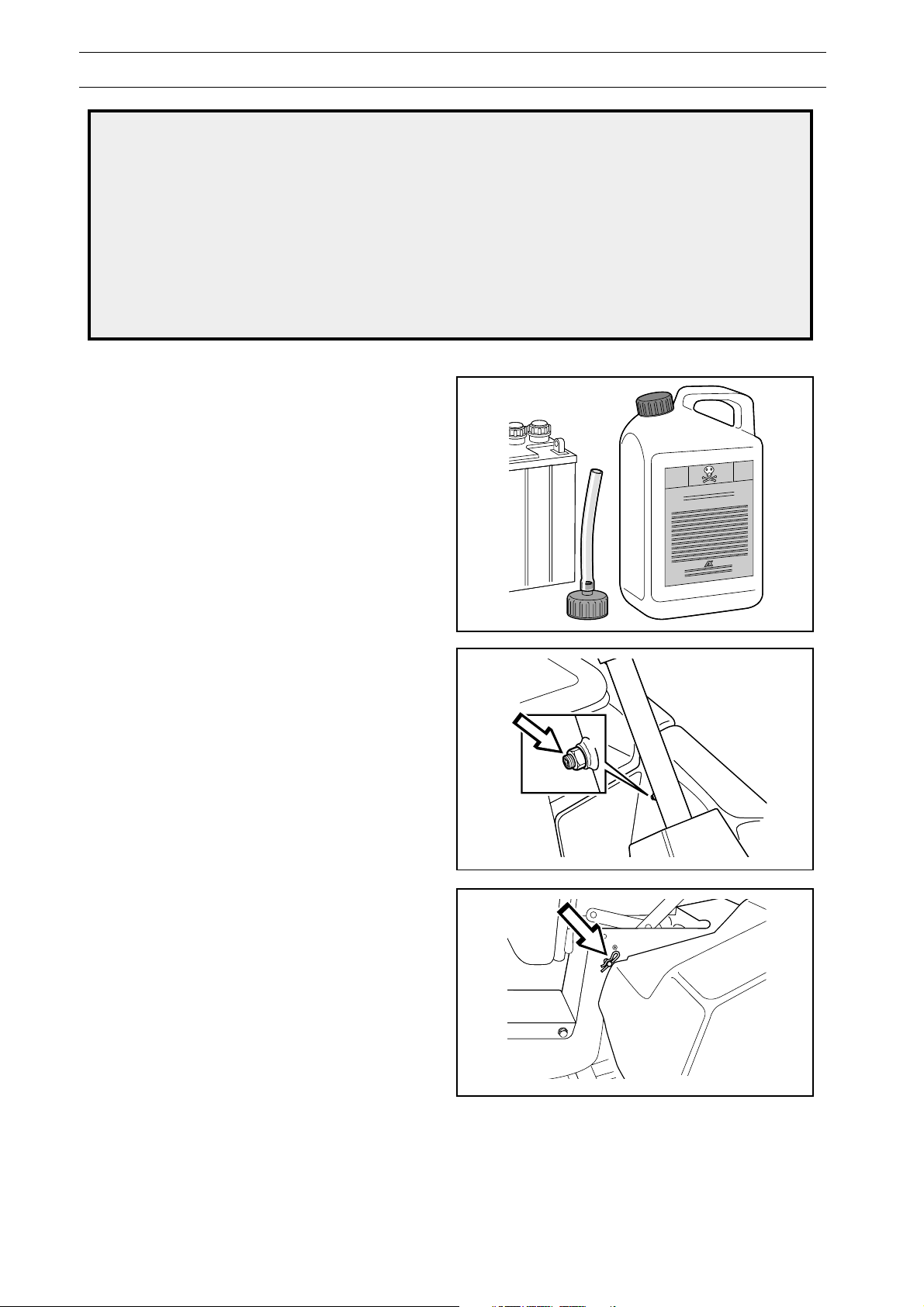
WARNING!
The battery acid is highly corrosive. Use rubber gloves and protective glasses.
Avoid breathing in the acid fumes.
!
External: Rinse thoroughly with water.
Internal: Drink large quantities of water or milk. Contact a doctor as soon as possible.
Eyes: Rinse thoroughly with water. Contact a doctor as soon as possible.
The battery gives off explosive gas. Sparks, flames, and cigarettes must absolutely not be in
the near vicinity of the battery.
Filling battery acid
The battery is delivered dry from the factory.
• Slowly fill the battery acid (not included) up to
the mark on the battery.
Measures for contact with acid
• Wait 20 minutes and fill, as is required, with
more battery acid.
• Charge the battery (12V, 6A) for one hour.
• Check the level of acid and fill, as is required,
with distilled water up to the correct level.
Fastening steering wheel
• Fasten the steering wheel with steering column
on the steering shaft.
• Tighten the socket head cap screw, make sure
that it sits in its groove on the steering shaft.
• Securely lock the socket head cap screw with
the locking nut.
Fastening seat
Insert the seat pin through the hole in the frame and
seat attachment and fasten spring pin.
4
www.mymowerparts.com
Page 5
For Husqvarna Parts Call 606-678-9623 or 606-561-4983
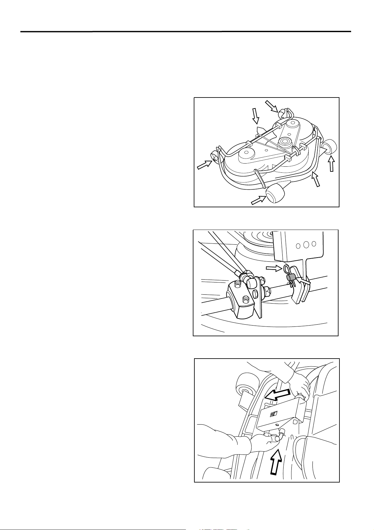
Installation of the Cutting Deck
Fitting the cutting unit
1. Position the Rider on a flat surface and apply
the parking brake. Check that the
lever for adjusting the cutting height is at the
lowest setting.
Make sure the two rear support wheels are fitted to
cutting unit (1).
the
*NOTE: Be sure to remove these two rear support
wheels (1) before operating unit. These wheels are
to be stored and only installed when servicing the
mower deck. These wheels allow you to "Flip Up"
the cutting deck for easy service access.
1
3
(The two front mounted deck wheels (4) are
permanently mounted to the deck frame and function
as gauge wheels)
2.
Hold the frame of the cutting unit (2) and slide
the unit underneath the rider mower, making
sure that the tongue on the cutting unit (3)
engages correctly.
Insert the bolt (1) and secure it with a
3.
locking pin (2).
1
4
2
4
2
1
4. Press down the frame (1) and insert the pin (2).
Fit the
cutting unit.
5. Hook up the height adjustment strut.
6. Fit the front cover.
7. Fit the spring that tensions the belt tensioning
pulley.
drive belt around the drive wheels of the
www.mymowerparts.com
1
2
5
Page 6
For Husqvarna Parts Call 606-678-9623 or 606-561-4983
MAINTENANCE
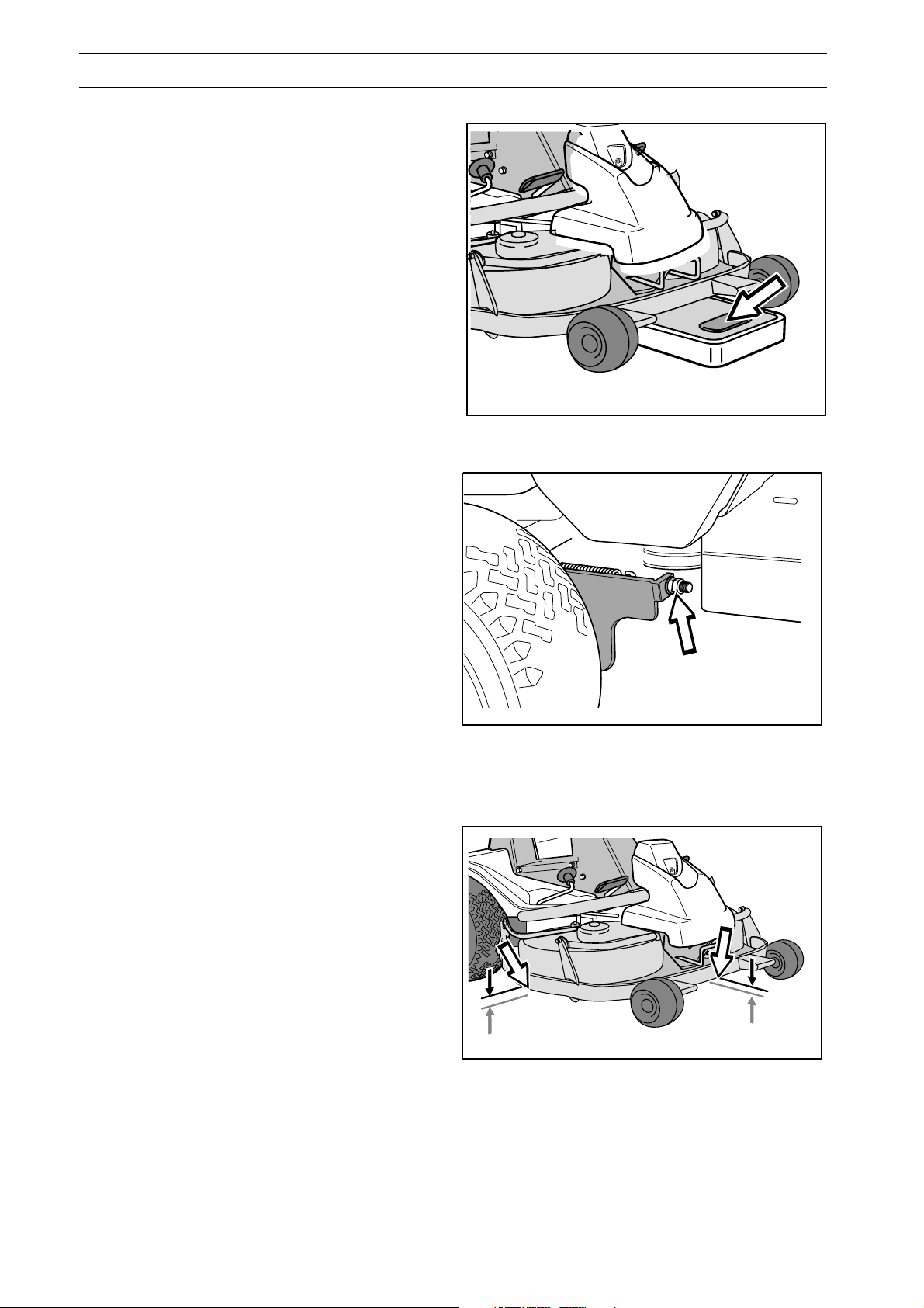
Checking and adjustment of the
cutting unit’s ground pressure
To achieve the best cutting results the cutting unit
should follow the underlying surface without
pressing too hard against it.
The pressure is adjusted with a screw on each
side of the machine.
1. Place a set of bathroom scales under the
cutting unit’s frame (front edge) so that it rests
on the scales. If necessary a block can be
placed between the frame and scales so that
the support wheels do not bear any weight.
2. Adjust the unit’s ground pressure by screwing
in or out the adjusting screws located behind
the front wheels on both sides.
The ground pressure should be between 12
and 15 kg (26-33 lbs).
Checking the cutting unit’s
rake angle (pitch)
Check the pitch of the cutting unit as follows:
1. Place the machine on a level surface.
2. Measure the distance between the ground and
the front and rear edges of the cutting unit
hood. The cutting unit should slope forwards
slightly so that the rear edge is 2-4 mm
(.08 -.16 in) higher
than the front edge.
6
www.mymowerparts.com
Page 7
For Husqvarna Parts Call 606-678-9623 or 606-561-4983
MAINTENANCE
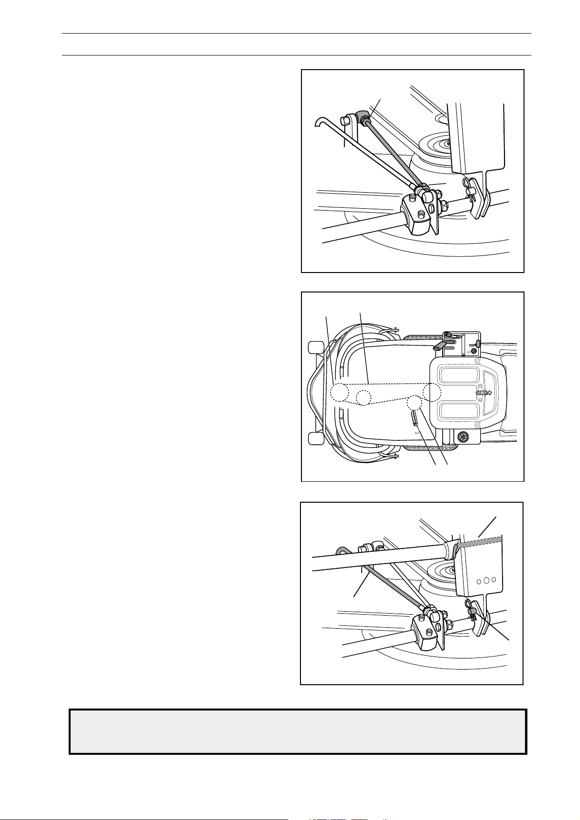
Adjusting the rake angle (pitch)
of the
1. Remove the front hood and right-hand fender.
2. Undo the nuts on the lift strut (1).
cutting unit
1
3. Unscrew the strut (counterclockwise) to lo
rear edge of the hood.
the
Screw the strut in (clockwise) to raise the rear
edge of the hood.
4. Tighten the nuts after adjustment.
5. On completion of the adjustment, the unit
rake angle (pitch) should be re-checked.
6. Fit the right-hand fender and the front hood.
wer
’
s
Removing the cutting unit
1. Apply the parking brake.
2. Adjust the cutting height to its lowest setting.
3. Remove the front hood.
4. Fit the two service suppor
5. Relieve the tensioning wheel (2) by disconnecting the spring (1).
6. Lift the drive belt (3) off the cutting unit drive
pulley (4).
t wheels.
1
4
3
7. Pull out the pin (2) and hang the drive belt on
the pin.
8. Put your foot on the front edge of the cutting
unit. Raise the front edge of the cutting unit
slightly and unhook the lift strut (1).
9. Remove the bolt (3) and pull out the cutting
unit.
Fitting of the cutting unit takes place in the reverse
order to removal.
During fitting: make sure that the tongue on the
cutting unit engages in the correct position.
WARNING!
!
up the belt can go off and cause personal injury.
Wear protective glasses when dismantling the cutting unit. The spring which tensions
1
2
2
1
3
7
www.mymowerparts.com
Page 8
For Husqvarna Parts Call 606-678-9623 or 606-561-4983
MAINTENANCE
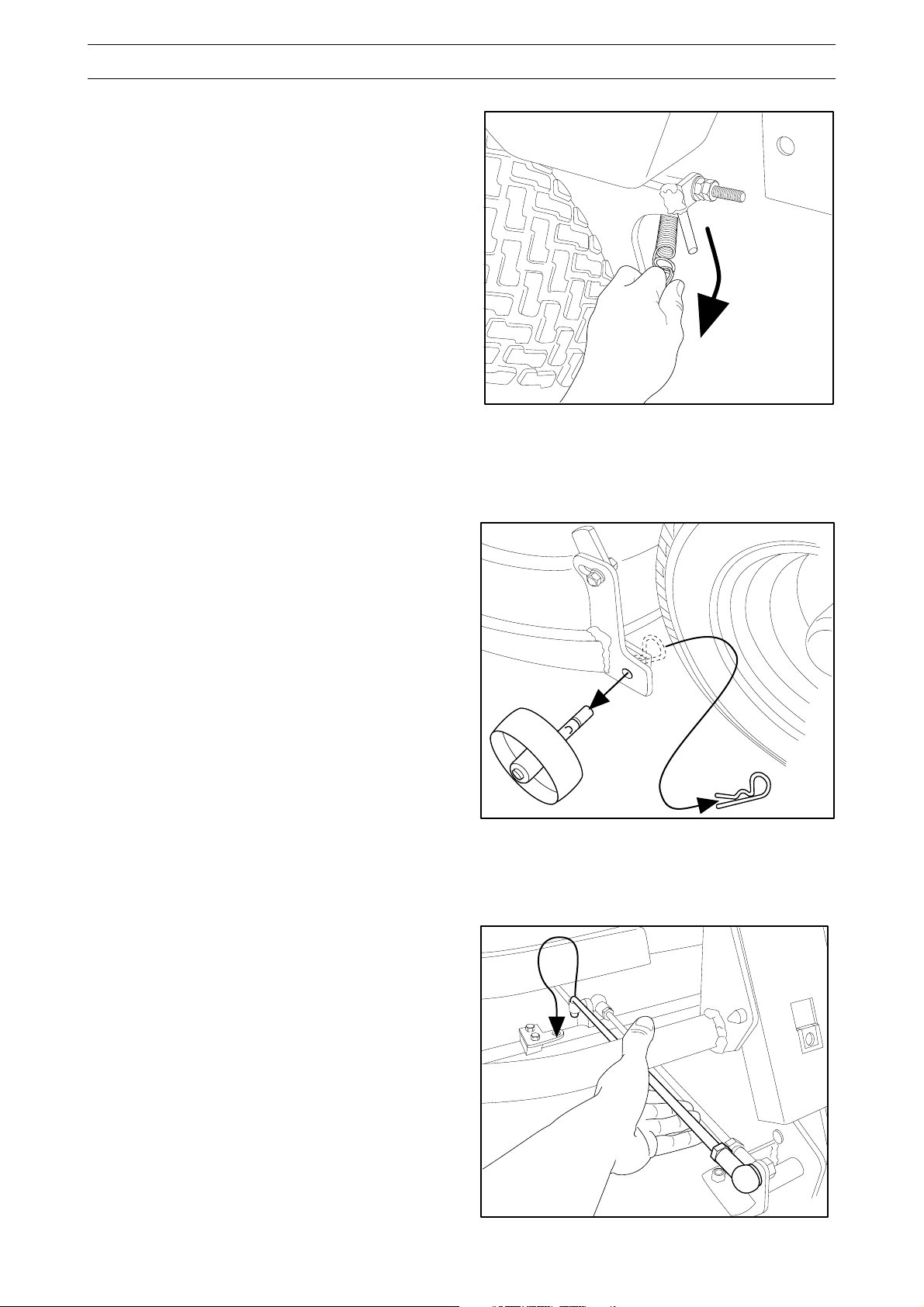
Service position for cutting unit
The cutting head can be placed in the service
position to provide easy access for cleaning, repairs
and servicing. In the service position the cutting unit
is raised and locked in the vertical position.
Placing in service position
1. Apply the parking brake (see operator's manual).
Adjust the
2. Disengage the spring from the drive belt
tensioning wheel.
cutting unit to the lowest cutting height.
3. Fit the support wheels (1) and lock with the
locking pin (2).
4. Remove the front hood and pull
out the pin.
5. Place a foot on the edge of the cutting unit near
the wheel and raise the front edge of the unit to
make it easier to remove the lift strut. Engage
the strut in the holder.
1
2
8
www.mymowerparts.com
Page 9
For Husqvarna Parts Call 606-678-9623 or 606-561-4983
MAINTENANCE
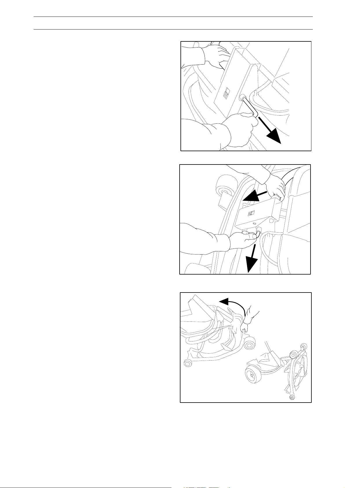
6. Pull out the pin. Lift off the drive belt and lay it on
the pin. Take care not to get your hand trapped.
7. Push down the frame (1) and insert the pin (2).
8. Grasp the front edge of the cutting unit, pull out
and raise into the service position.
1
2
1
Restoring from service position
To restore the machine from the service position,
reverse the sequence "Placing in Service Position".
www.mymowerparts.com
2
9
Page 10
For Husqvarna Parts Call 606-678-9623 or 606-561-4983
WHEEL ASSEMBLY
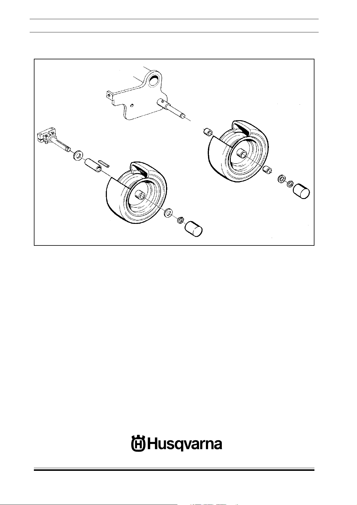
Assemble the wheels
Front
Rear
Assemble the wheels in the sequence as shown above.
www.mymowerparts.com
 Loading...