

Page 1

For Husqvarna Parts Call 606-678-9623 or 606-561-4983
We set the wheels in motion.
310-2400
Integrated Zero-Turn Transaxle
Service and Repair Manual
BLN-51134
March 2001
www.mymowerparts.com
Page 2

For Husqvarna Parts Call 606-678-9623 or 606-561-4983
Table of Contents
Section Page
Foreword ........................................................................................................................................ 1
Section 1 Description and Operation .......................................................................................... 2
Introduction ........................................................................................................................................................ 2
General Description ............................................................................................................................................ 2
Hydraulic Schematic ........................................................................................................................................... 3
External Features 310-2400L ............................................................................................................................. 4
External Features 310-2400R ............................................................................................................................. 5
Technical Specifications ..................................................................................................................................... 6
Product Identification .......................................................................................................................................... 6
Section 2 Safety .............................................................................................................................7
Personal Safety .................................................................................................................................................. 7
Tool Safety ......................................................................................................................................................... 7
Work Area Safety ............................................................................................................................................... 7
Servicing Safety ................................................................................................................................................. 7
Section 3 Troubleshooting ........................................................................................................... 8
Section 4 Service and Maintenance ............................................................................................. 9
External Maintenance ......................................................................................................................................... 9
Service and Maintenance Procedures ................................................................................................................ 9
Fluids ............................................................................................................................................................... 10
Purging Procedures .......................................................................................................................................... 11
Return to Neutral Setting .................................................................................................................................. 12
Brake Maintenance .......................................................................................................................................... 13
Friction Pack Adjustment .................................................................................................................................. 13
Section 5 Repair .......................................................................................................................... 14
How To Use This Section ................................................................................................................................. 14
General Instructions ......................................................................................................................................... 14
Transaxle Removal .......................................................................................................................................... 14
Limited Disassembly ........................................................................................................................................ 14
Tools and Torques ........................................................................................................................................... 15
Back Cover ...................................................................................................................................................... 16
Brakes ........................................................................................................................................................17-18
Brake Shaft & Bevel Gear ................................................................................................................................ 19
Axle Shaft & Spur Gear ............................................................................................................................... 20-21
Lower Housing and Filter .................................................................................................................................. 22
Motor Shaft & Bevel Gear ................................................................................................................................. 23
Center Section, Cylinder Blocks and Bypass ...............................................................................................24-25
Input Shaft & Trunnion Arm ......................................................................................................................... 26-27
Transaxle Installation ....................................................................................................................................... 28
Assembly After a Complete Teardown .............................................................................................................. 28
Sealant Application ..................................................................................................................... 29
Parts List ................................................................................................................................. 30-31
Glossary of Terms ..................................................................................................................32-33
www.mymowerparts.com
Page 3

For Husqvarna Parts Call 606-678-9623 or 606-561-4983
FOREWORD
Headquartered in Sullivan, Illinois, Hydro-Gear
is a world leader in the design, manufacture,
and service of quality hydrostatic transaxles for
the lawn and garden industry. The mission of
our company is to be recognized by our
customers and the industry as a world-class
supplier and the quality leader in everything we
do.
This Service and Repair Manual is designed to
provide information useful in servicing the
Hydro-Gear 310-2400, referred to as the
Integrated Zero Turn (IZT).
Also included is a glossary of terms that are
frequently used throughout the industry and in
Hydro-Gear service publications. Understanding terminology is very important!
It is necessary, and good shop practice, that
your service area be equipped with proper tools
and the mechanics to be supplied with the
latest information available. All repair
procedures illustrated in this guide are
suggested, but preferred methods of repair.
Some repair procedures require that the IZT be
removed from the vehicle.
This is not a certification, test or study guide for
a certification test. If a technician is interested
in certification they should contact an agent
representing the ESA (Engine Service Association) (610) 363-3844 or their Hydro-Gear Distributor. Many distributors will be hosting
certification testing. These study guides will
cover most of the products and manufacturers
in our industry.
For more information about Hydro-Gear or our
products, please contact your Central Service
Distributor, or call our Customer Service
Department at (217) 728-2581.
310-2400 IZT
1
www.mymowerparts.com
Page 4

For Husqvarna Parts Call 606-678-9623 or 606-561-4983
SECTION 1. DESCRIPTION AND OPERATION
INTRODUCTION
The purpose of this manual is to provide
information useful in servicing the Hydro-Gear
Integrated Zero Turn (IZT) transaxle. This manual includes the IZT’s general description, hydraulic schematic, technical specifications, servicing and troubleshooting procedures.
The transaxle normally will not require servicing
during the life of the vehicle in which it is
installed. Should other servicing be required,
the exterior of the transaxle will need to be
thoroughly cleaned before beginning most
procedures.
GENERAL DESCRIPTION
The 310-2400 is a self contained unit designed
for the transfer and control of power. It provides
an infinitely variable speed range between zero
and maximum in both forward and reverse
modes of operation.
This transaxle uses a variable displacement
pump with a maximum displacement of 10cc
per revolution, and motor with a fixed displacement of 21cc per revolution. The variable displacement pump features a cradle mounted
swashplate with a direct-proportional displacement control. Reversing the direction of the
swashplate reverses the flow of oil from the
pump and thus reverses the direction of the
motor output rotation. The pump and motor are
of the axial piston design and utilize spherical
nosed pistons which are held against a thrust
race by internal compression springs.
The 310-2400 has a self contained fluid supply
and an internal filter. The fluid is forced through
the filter by a positive “head” on the fluid in the
housing/expansion tank with an assist by the
negative pressure created in the pump pistons
as they operate.
The check valves in the center section are used
to control the makeup flow of the fluid to the low
pressure side of the loop.
A bypass is utilized in the 310-2400 to permit
moving the vehicle for a short distance at a
maximum of 2 m.p.h. (3.2 Km/h) without starting the engine.
WARNING
Actuating the bypass will result in the
loss of hydrostatic braking capacity.
The machine must be stationary on a
level surface and in neutral when
actuating the bypass.
The 310-2400 is configured for both floating
disc and cog style parking brakes.
Figure 1. 310-2400 Hydraulic Schematic
2
310-2400 IZT
www.mymowerparts.com
Page 5

For Husqvarna Parts Call 606-678-9623 or 606-561-4983
CYLINDER BLOCK
ASSEMBLY
FIXED
SWASHPLATE
FIXED
DISPLACEMENT
21cc MOTOR
MOTOR
SHAFT
INPUT
SHAFT
VARIABLE
SWASHPLATE
CYLINDER
BLOCK
ASSEMBLY
VARIABLE
DISPLACEMENT
10cc PUMP
CHECK VALVE
CHECK VALVE
BYPASS
ACTUATOR
TRANSAXLE
HOUSING
RESERVOIR
FILTER
Figure 2. 310-2400 Hydraulic Flow Illustration
HYDRAULIC SCHEMATIC
Figure 2 provides an illustration of the hydraulic
oil circuit. The oil supply for the hydraulic
system of the 310-2400 IZT is also utilized for
lubricating the components of the final drive
assembly.
The input shaft and pump cylinder block are
turned in one direction only by the engine/drive
belt/pulley combination. Output of the oil flow is
controlled by the direction and amount that the
variable swashplate is angled. As the pump
pistons compress they force the oil to flow
through one of two passageways (forward or
reverse) in the center section to the motor
cylinder block and motor shaft. Since the motor
has a fixed displacement angle it is forced to
turn with the flow of oil. As the angle of the
pump swashplate is increased the amount of oil
being pumped will increase and cause a higher
speed output of the motor. Reversing the angle
of the swashplate will reverse the direction of
oil flow.
designed into the product for lubrication
purposes (around pistons, under the rotating
cylinder blocks, etc.). This “lost” fluid returns to
the transaxle housing, then is pulled back into
one of the check valves depending upon the
direction of vehicle operation. All of this oil
must pass through an internal filter.
The motor cylinder block mounts onto a splined
motor shaft which drives the gear train.
The bypass feature in the 310-2400 has a
mechanical lever which lifts the motor block off
of the center section running surface, allowing
any oil flowing from the pump block to be
discharged into the housing without turning the
motor.
During the operation of the transaxle, fluid is
“lost” from the hydraulic loop through leak paths
310-2400 IZT
www.mymowerparts.com
3
Page 6

For Husqvarna Parts Call 606-678-9623 or 606-561-4983
EXTERNAL FEATURES 310-2400L
Back Cover
Back Cover
Axle Shaft
Disc Brake Assembly
Fill Port
Input Shaft
Hub
Assembly
Bypass
Actuator
Cog Brake Assembly
4
Seal Plug
www.mymowerparts.com
Lower Cover
Control Arm
Assembly
310-2400 IZT
Page 7

For Husqvarna Parts Call 606-678-9623 or 606-561-4983
EXTERNAL FEATURES 310-2400R
Back Cover
Back Cover
Axle Shaft
Hub
Assembly
Bypass
Actuator
Input Shaft
Disc Brake Assembly
Fill Port
310-2400 IZT
Control Arm
Assembly
Lower Cover
www.mymowerparts.com
Seal Plug
Cog Brake Assembly
5
Page 8

For Husqvarna Parts Call 606-678-9623 or 606-561-4983
TECHNICAL SPECIFICATIONS
Technical specifications for the 310-2400 IZT are listed in Table 1.
Overall Transaxle Reduction
19.2:1
Input Speeds
Maximum: 3000 RPM
Minimum: 1800 RPM
Tire Diameter
18 in; 45.7cm with 325 lbs; 147.4 kg
maximum weight on tires
Table 1. 310-2400 Technical Specifications
Axle Shaft Options
Type: Keyed / Double “D”
Diameter: 0.984 inch; 25.0 mm
Type: Flanged
Diameter: Hub
Brake Type
Disc, Parking
Cog, Parking
Weight of Unit
30 lb; 14 kg
PRODUCT IDENTIFICATION
The model and configuration of the 310-2400 IZT can be determined from the label shown in
Figure 3.
H Y D R O - G E A R
H Y D R O - G E A R
SULLIVAN, IL. U.S.A.
SULLIVAN, IL. U.S.A.
I IIII III IIII II II
I IIII III IIII II II
Model
Model
Number
Number
Year Built
Year Built
Date
Date
(Julian - day of year)
(Julian - day of year)
13054 318-2400
13054 318-2400
I II IIII IIII II I III I II IIII
I II IIII IIII II I III I II IIII
0 319 Z1401 Made in U.S.A.
0 319 Z1401 Made in U.S.A.
Type of Product and Build Information
Type of Product and Build Information
318-2400L
Serial Number
Serial Number
(unique number for that model - for that day)
(unique number for that model - for that day)
Figure 3. 310-2400 Configuration Label
Hydro-Gear
Hydro-Gear
Ref. Number
Ref. Number
6
310-2400 IZT
www.mymowerparts.com
Page 9

For Husqvarna Parts Call 606-678-9623 or 606-561-4983
SECTION 2. SAFETY
This symbol points out important safety
instructions which, if not followed, could
endanger the personal safety and/or property of
yourself and others. Read and follow all
instructions in this manual before attempting
maintenance on your transaxle. When you see
this symbol - HEED ITS WARNING.
WARNING
POTENTIAL FOR SERIOUS INJURY
Inattention to proper safety, operation, or
maintenance procedures could result in personal injury, or damage to the equipment.
Before servicing or repairing the 310-2400
IZT, fully read and understand the safety
precautions described in this section.
Wear appropriate clothing. Loose or hanging
clothing or jewelry can be hazardous. Use the
appropriate safety equipment, such as eye and
hearing protection, and safety-toe and slipproof shoes.
Never use compressed air to clean debris from
yourself or your clothing.
TOOL SAFETY
Use the proper tools and equipment for the
task.
Inspect each tool before use and replace any
tool that may be damaged or defective.
WORK AREA SAFETY
Keep the work area neat and orderly. Be sure
it is well lit, that extra tools are put away, trash
and refuse are in the proper containers, and dirt
or debris have been removed from the working
areas of the machine.
PERSONAL SAFETY
Certain safety precautions must be observed
while servicing or repairing the 310-2400 IZT.
This section addresses some of these
precautions but must not be considered an allinclusive source on safety information. This
section is to be used in conjunction with all
other safety material which may apply, such as:
1) Other manuals pertaining to this machine,
2) Local and shop safety rules and codes,
3) Governmental safety laws and regulations.
Be sure that you know and understand the
equipment and the hazards associated with it.
Do not place speed above safety.
Notify your supervisor whenever you feel there
is any hazard involving the equipment or the
performance of your job.
Never allow untrained or unauthorized personnel to service or repair the equipment.
The floor should be clean and dry, and all extension cords or similar trip hazards should be
removed.
SERVICING SAFETY
Certain procedures may require the vehicle to
be disabled in order to prevent possible injury
to the servicing technician and/or bystanders.
The loss of hydrostatic drive line power may result in the loss of hydrostatic braking capability.
Proper brake maintenance is very important
should this condition develop.
Some cleaning solvents are flammable. Use
only approved cleaning materials. Do not use
explosive or flammable liquids to clean the
equipment.
To avoid possible fire do not use cleaning solvents in an area where a source of ignition may
be present.
Discard used cleaning material in the appropriate containers.
310-2400 IZT
7
www.mymowerparts.com
Page 10
For Husqvarna Parts Call 606-678-9623 or 606-561-4983
SECTION 3. TROUBLESHOOTING
WARNING
Do not attempt any servicing or adjustments with the engine running.
Use extreme caution while inspecting the
drive belt assembly, and all vehicle linkage!
Follow all safety procedures outlined in
the vehicle owner’s manual!
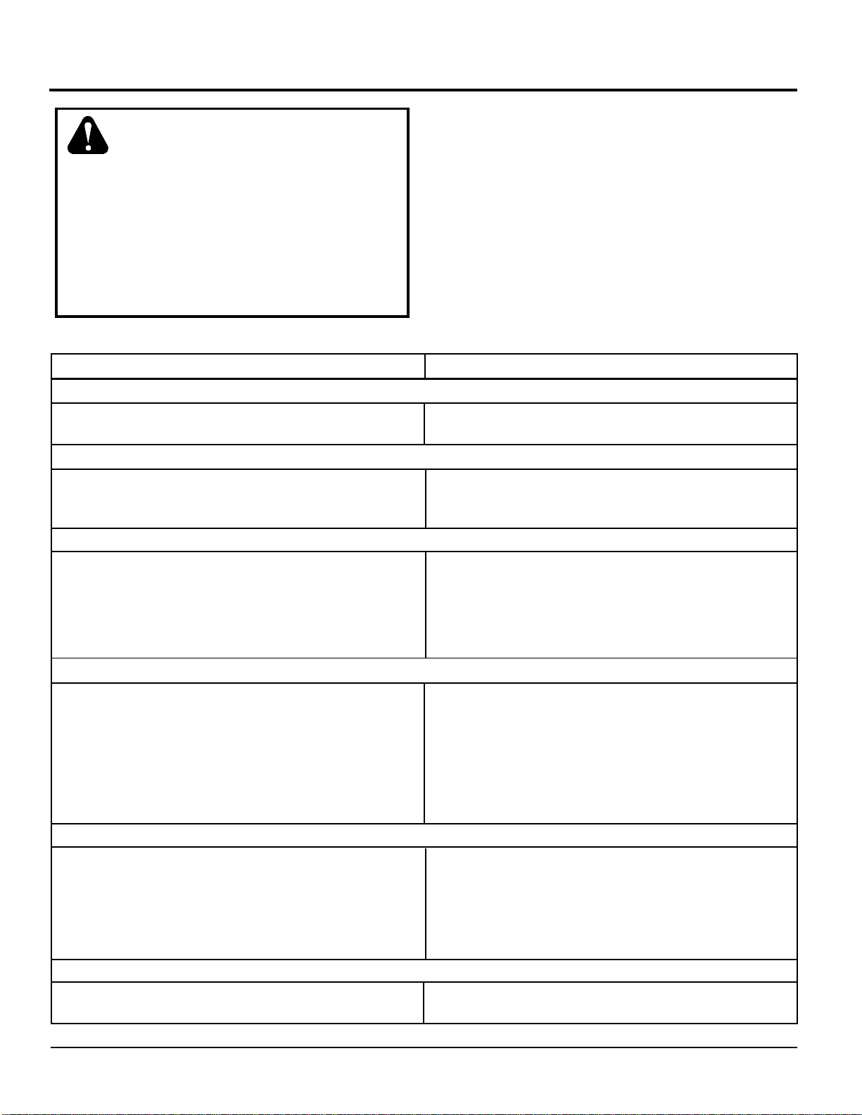
Table 2. 310-2400 Troubleshooting Checklist
UNIT OPERATES IN ONE DIRECTION ONLY
Control linkage bent or out of adjustment
Drive belt slipping or pulley damaged
VEHICLE DOES NOT DRIVE/TRACK STRAIGHT
Vehicle tires improperly inflated
Control linkage bent, loose or out of adjustment
Bypass partially engaged
In many cases problems with the 310-2400 IZT
are not related to a defective transaxle, but are
caused by slipping drive belts, partially
engaged bypass valves, and loose or
damaged control linkages. Be sure to perform
all operational checks and adjustments outlined
in Section 4, Service and Maintenance before
assuming the unit is malfunctioning. Table 2
below provides a troubleshooting check list to
help determine the cause of operational problems.
Corrective Action Possible Cause
Repair or replace linkage, Page 9
Repair or replace drive belt or pulley, Page 9
Refer to vehicle manufacturer suggested pressure
Repair, adjust or replace vehicle linkage
Adjust bypass linkage
Oil level low or contaminated oil
Excessive loading
Brake setting incorrect
Loose parts
Bypass assembly sticking
Air trapped in hydraulic system
Engine speed low
Control linkage bent or out of adjustment
Brake setting incorrect
Drive belt slipping or pulley damaged
Oil level low or contaminated oil
Excessive loading
Bypass assembly sticking
Air trapped in hydraulic system
Debris buildup around transaxle
Brake setting incorrect
Cooling fan damaged
Oil level low or contaminated oil
Excessive loading
Air trapped in hydraulic system
UNIT IS NOISY
Fill to proper level or change oil, Page 10
Reduce vehicle loading, Page 9
Adjust brake to proper setting, Page 13
Repair or replace loose parts
Repair or replace valve or linkage
Purge hydraulic system, Page 11
UNIT HAS NO/LOW POWER
Adjust to correct setting
Repair or replace linkage, Page 9
Adjust brake to proper setting, Page 13
Repair or replace drive belt or pulley, Page 9
Fill to proper level or change oil, Page 10
Reduce vehicle loading, Page 9
Repair or replace valve or linkage
Purge hydraulic system, Page 11
UNIT OPERATING HOT
Clean off debris, Page 9
Adjust brake to proper setting, Page 13
Repair or replace cooling fan
Fill to proper level or change oil, Page 10
Reduce vehicle loading, Page 9
Purge hydraulic system, Page 11
Damaged seals, housing, or gaskets
Air trapped in hydraulic system
8
TRANSAXLE LEAKS OIL
Replace damaged component
Purge hydraulic system, Page 11
310-2400 IZT
www.mymowerparts.com
Page 11

For Husqvarna Parts Call 606-678-9623 or 606-561-4983
SECTION 4. SERVICE AND MAINTENANCE
NOTE: Any servicing dealer attempting
a warranty repair must have prior
approval before conducting maintenance
of a Hydro-Gear product unless the
servicing dealer is a current Authorized
Hydro-Gear Service Center.
EXTERNAL MAINTENANCE
Regular external maintenance of the 310-2400
IZT should include the following:
1. Check the vehicle operator’s manual for
the recommended load ratings. Insure
the current application does not exceed
load rating.
2. Check oil level in accordance with Figure 4
Page 10.
3. Inspect the vehicle drive belt, idler pulley(s),
and idler spring(s). Insure that no belt
slippage can occur. Slippage can cause low
input speed to the transmission.
SERVICE AND MAINTENANCE
PROCEDURES
All the service and maintenance procedures
presented on the following pages can be
performed while the 310-2400 is mounted on
the vehicle. Any repair procedures as
mentioned in the repair section of this manual
must be performed after the unit has been
removed from the vehicle.
4. Inspect the transmission cooling fan for
broken or distorted blades and remove any
obstructions (grass clippings, leaves, dirt,
etc.).
5. Inspect the axle parking brake and vehicle
linkage to insure proper actuation and
adjustment of the parking brake.
6. Inspect the vehicle control linkage to the
directional control arm on transaxle. Also,
insure the control arm is securely fastened
to the trunnion arm of the transaxle.
7. Inspect the bypass mechanism on the
transaxle and vehicle linkage to insure it
actuates and releases fully.
310-2400 IZT
9
www.mymowerparts.com
Page 12
For Husqvarna Parts Call 606-678-9623 or 606-561-4983
FLUIDS
The fluids used in Hydro-Gear products have
been carefully selected, and only equivalent, or
better products should be substituted.
Typically, an engine oil with a minimum rating
of 55 SUS at 212°F (100° C) and an API classification of SL is recommended. A 20W-50 engine oil has been selected for use by the factory and is recommended for normal operating
temperatures.
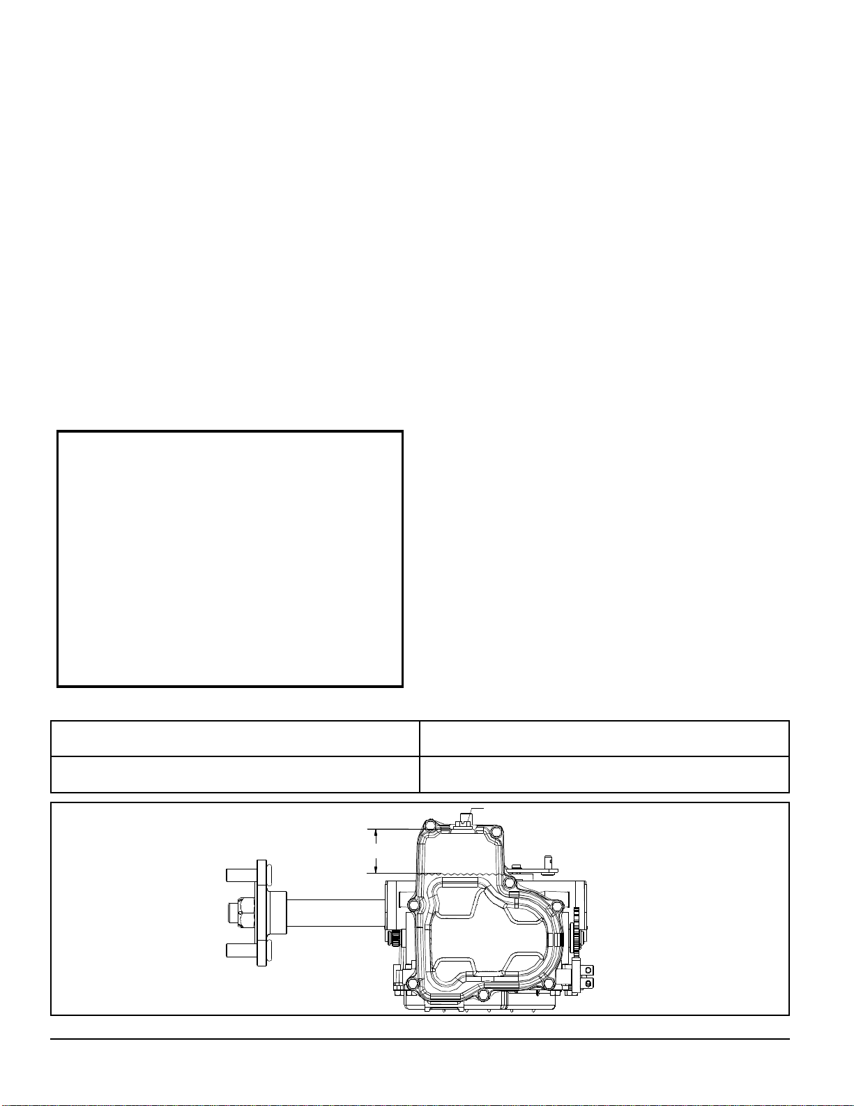
FLUID VOLUME AND LEVEL
Fluid volume information is provided in Table 3.
Certain situations may require additional fluid to
be added or even replaced. Refer to Figure 4
for the proper fill port location.
CAUTION
Do not overfill.
If you overfill the transaxle while the unit
is “cold”, it may overflow as it reaches
normal operating temperatures. The oil
level should not be above the
manufacturer’s suggestions outlined in
this manual. This will allow the space
needed for the oil to expand as it warms
up.
Recheck the fluid level once the unit has been
operated for approximately 1 minute.
Purging may be required. Refer to the purging
procedures on page 11.
FLUID CHANGE
This transaxle is factory filled, sealed and does
not require oil maintenance. However, in the
event of oil contamination or degradation, oil
addition or change may alleviate certain performance problems.
It is essential that the unit exterior be free of
debris prior to fluid maintenance. The transaxle must be removed from the vehicle for oil
drainage from the top.
10
Table 3. Fluid Volumes for the 310-2400 IZT
Fluid Description Volume
20W-50 engine oil 79 fl. oz. (2336 ml.)
FILL PORT
1?" (48.0 mm)
OIL
LEVEL
Figure 4. 310-2400 Fluid Level and Fill Port
www.mymowerparts.com
310-2400 IZT
Page 13

For Husqvarna Parts Call 606-678-9623 or 606-561-4983
PURGING PROCEDURES
Due to the effects air has on efficiency in
hydrostatic drive applications, it is critical that it
be purged from the system.
These purge procedures should be implemented any time a hydrostatic system has
been opened to facilitate maintenance or any
additional oil has been added to the system.
Air creates inefficiency because its compression and expansion rate is higher than that of
the oil normally approved for use in hydrostatic
drive systems.
The resulting symptoms in hydrostatic systems
may be:
1. Noisy operation.
2. Lack of power or drive after short term
operation.
3. High operation temperature and excessive
expansion of oil.
Before starting, make sure the transaxle/
transmission is at the proper oil level. If it is
not, fill to the specifications outlined on page
10, Figure 4.
The following procedures should be performed
with the vehicle drive wheels off the ground,
then repeated under normal operating conditions.
1. With the bypass valve open and the engine
running, slowly move the directional control
in both forward and reverse directions 5 to 6
times, as air is purged from the unit, the oil
level will drop.
2. With the bypass valve closed and the
engine running, slowly move the directional
control in both forward and reverse
directions (5 to 6 times). Check the oil level,
and add oil as required after stopping
engine.
3. It may be necessary to repeat Steps 1 and 2
until all the air is completely purged from the
system. When the transaxle moves forward
and reverse at normal speed purging is
complete.
310-2400 IZT
11
www.mymowerparts.com
Page 14
For Husqvarna Parts Call 606-678-9623 or 606-561-4983
RETURN TO NEUTRAL SETTING
WARNING
POTENTIAL FOR SERIOUS INJURY
Certain procedures require the vehicle
engine to be operated and the vehicle
to be raised off the ground. To prevent
possible injury to the servicing technician and/or bystanders, insure the
vehicle is properly secured.
The return to neutral mechanism on the transmission is designed to set the directional control into a neutral position when the operator removes their hands from the control. Follow the
procedures below to properly adjust the return
to neutral mechanism on the transaxle:
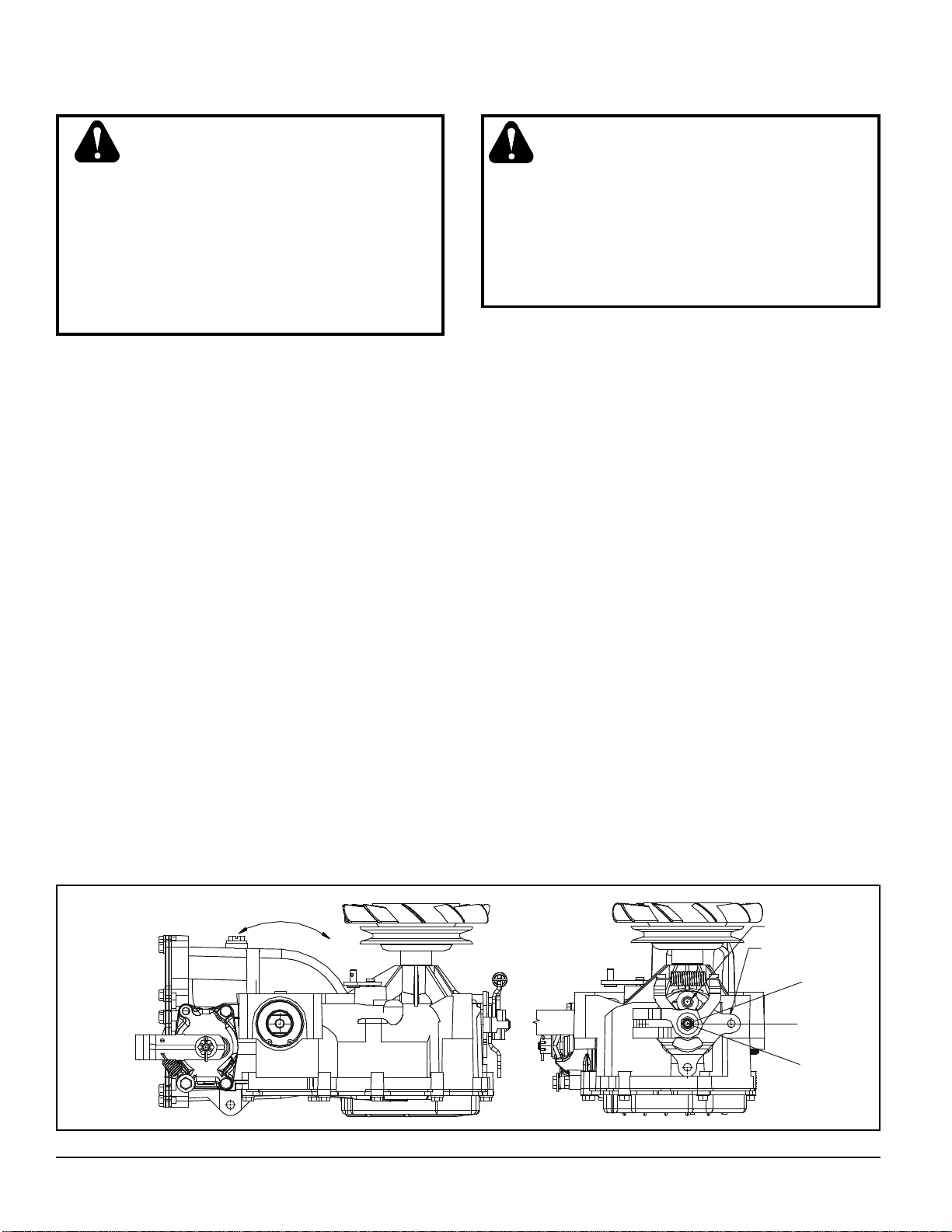
1. Confirm the transaxle is in the operating mode (bypass disengaged). Raise the
vehicle’s drive tires off the ground to allow
free rotation.
NOTE: It may be necessary to remove
the drive tire from the axle hub to access
the linkage control and the transaxle
return arm.
2. Remove the Original Equipment Manufacturer’s (OEM’s) control linkage at the return
arm. Refer to Figure 7.
3. Start the engine and increase the throttle to
full engine speed.
WARNING
Do not attempt any adjustments with the
engine running. Use extreme caution while
inspecting all vehicle linkage!
Follow all safety procedures outlined in the
vehicle owner’s manual.
4. Check for axle rotation. If the axles do not
rotate, go to Step 5. If the axles rotate, go to
Step 6.
5. Stop the vehicle’s engine. Reattach and adjust the OEM linkage to the return arm according to the OEM manual. Recheck according to Step 3 and 4. Stop the vehicle
engine. Refer to Figure 7.
6. Note the axle directional movement. Stop
the vehicle engine. Loosen the lock down
screw until the return arm can be rotated.
Refer to Figure 7 below to make adjustment. In general, rotate the return arm in
the direction opposite of axle rotation. If the
axle is rotating in the “B” direction, rotate
the return arm in the “A” direction, and viceversa. Continue until axle rotation stops.
Tighten the lock down screw. Refer to Table
3 Required Torque Values, Page 6. Recheck according to steps 3 and 4. Stop the
vehicle engine. Reattach and adjust the
OEM linkage according to the OEM manual.
Recheck according to steps 3 and 4. Refer
to Figure 7.
12
AXLE ROTATION “B”
AXLE ROTATION “A”
Figure 7. Return to Neutral Control
www.mymowerparts.com
LOCK DOWN SCREW
RETURN ARM
AXLE ROTATION “A”
AXLE ROTATION “B”
310-2400 IZT
Page 15
For Husqvarna Parts Call 606-678-9623 or 606-561-4983
COG BRAKE MAINTENANCE
1. Check the brake arm teeth for damage or
excessive wear. Replace if necessary.
2. Check for excessive looseness at brake arm
pivot point.
DISC BRAKE MAINTENANCE
1. Remove the brake return spring, and then
the cotter pin securing the brake castle nut.
2. Insert a 0.020" (0.5 mm) feeler gage between the brake rotor and outer brake friction stator, and then set the brake by tightening or loosening the castle nut.
3. Install a new cotter pin to secure the castle
nut, and then install the brake arm bias
spring.
BRAKE MAINTENANCE
FRICTION PACK ADJUSTMENT
The friction pack dampens or holds the operator control lever in its desired position.
Adjustment for the amount of drag or holding
force can be made by turning the friction pack
nut in or out.
Adjustments should be made in no more than
1/4 turn increments.
Over-tightening will result in difficulty or inability
of the operator to move the control lever.
Note: The factory setting for the friction pack is
assembly of the nut to 100 in-lbs (11 Nm)
torque. The friction pack nut is then backed off
per vehicle manufacturer’s specifications.
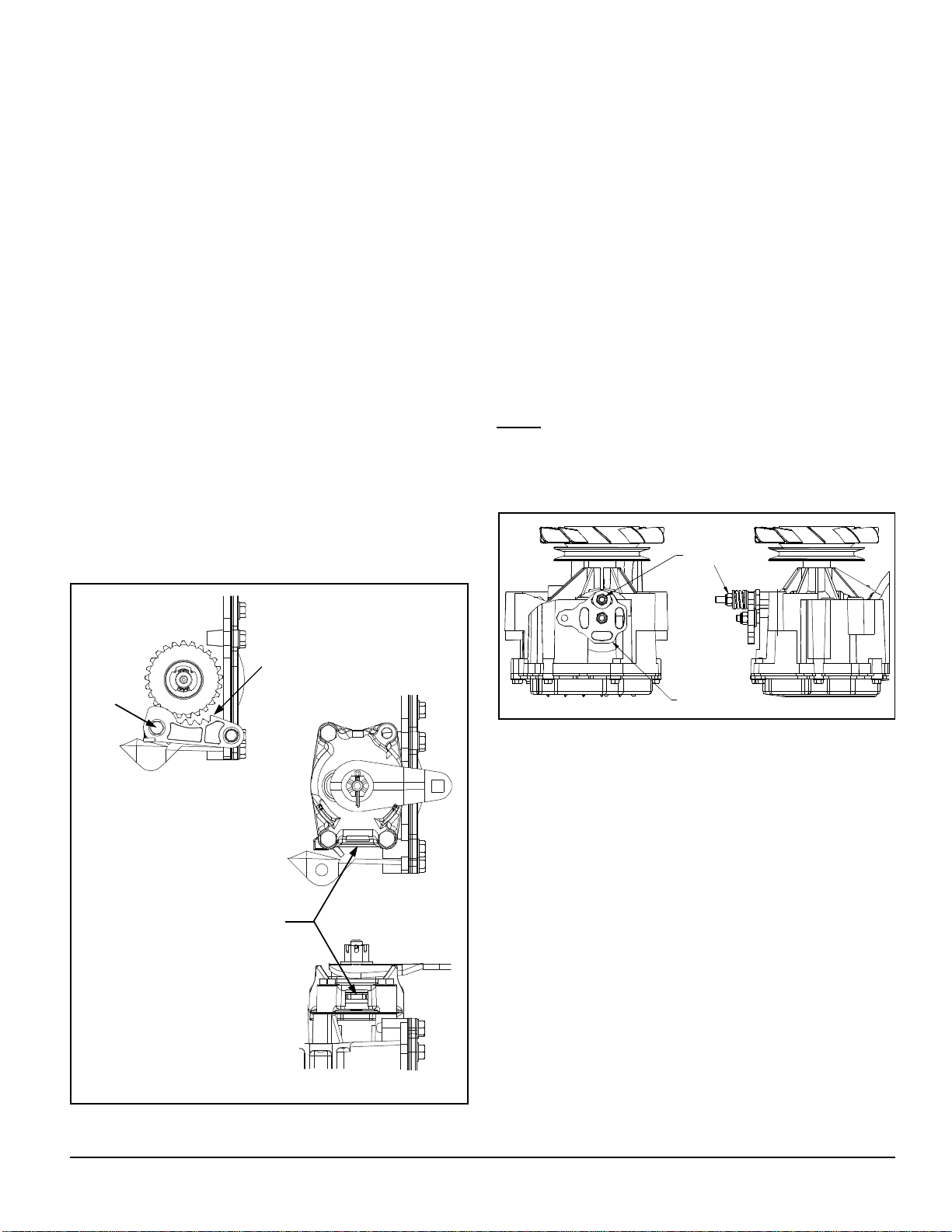
FRICTION PACK
ADJUSTING NUT
PIVOT
COG PARKING BRAKE
BRAKE SETTING LOCATION
BRAKE ARM TEETH
CONTROL ARM
Figure 6. Friction Pack
DISC PARKING BRAKE
310-2400 IZT
Figure 5. Brake Options
13
www.mymowerparts.com
Page 16
For Husqvarna Parts Call 606-678-9623 or 606-561-4983
SECTION 5. REPAIR
HOW TO USE THIS SECTION
Each subassembly illustrated in this section is
illustrated by an exploded view showing the
parts involved. The item reference numbers
in each illustration are for assembly
instructions only. See pages 32 and 33 for
part names and descriptions. A complete exploded view and item list of the transaxle is provided at the end of this section.
Many of the parts and subassemblies of this
transaxle can be removed and serviced independently of other components. Where some
components and assemblies must be removed
before a given assembly can be serviced, that
information is given at the beginning of the
disassembly instructions.
GENERAL INSTRUCTIONS
Cleanliness is a primary means of assuring
satisfactory life on repaired units. Thoroughly
clean all exposed surfaces prior to any type of
maintenance. Cleaning of all parts by using a
solvent wash and air drying is usually
adequate. As with any precision equipment, all
parts must be kept free of foreign material and
chemicals.
Protect all exposed sealing surfaces and open
cavities from damage and foreign material. The
external surfaces should be cleaned before
beginning any repairs.
Upon removal, it is recommended that all seals,
O-rings, and gaskets be replaced. During
installation lightly lubricate all seals, O-rings,
gaskets with a clean petroleum jelly prior to
assembly. Also protect the inner diameter of
seals by covering the shaft with a cellophane
(plastic wrap, etc.) material.
Parts requiring replacement must be replaced
from the appropriate kits identified in the Items
Listing, found at the end of this manual. Use
only original Hydro-Gear replacement parts
found listed in BLN-50937 (microfiche) or
BLN-51427 (CD).
TRANSAXLE REMOVAL
It is necessary to remove the 310-2400 from
the vehicle before performing the repair
procedures presented in this section. Use the
following procedure to prepare the unit for
removal from the vehicle.
1. With the vehicle wheels on the ground,
loosen the ¾-16 hex nut (108, Figure 12)
Page 21, if so equipped. Use an air impact
wrench and a 1-1/8” socket to loosen the
nut.
2. Lift the vehicle wheels off the ground and
remove the nut completely.
3. Remove the wheel from the hub.
4. Using a wheel or gear puller, remove the
hub from the shaft.
CAUTION
USE CARE IN REMOVING THE HUB TO
PREVENT CRACKING.
LIMITED DISASSEMBLY
The following procedures are presented in the
order in which they must be performed to
completely disassemble the unit. Do not
disassemble the unit any farther than is
necessary to accomplish the required repairs.
Each disassembly procedure is followed by a
corresponding assembly procedure.
Reassembly is accomplished by performing the
“Assembly” portions of the procedures. If the
unit has been completely disassembled, a summary of the assembly procedures, in the order
in which they should occur, is given on page
28.
14
310-2400 IZT
www.mymowerparts.com
Page 17

For Husqvarna Parts Call 606-678-9623 or 606-561-4983
TOOLS AND TORQUES
Table 4. Required Tools
Miscellaneous
310-2400 Service & Repair Manual
Flat Blade Screw Driver
Torque Wrench
Air Impact Wrench
Rubber Mallet
Pliers
Needle Nose
Large External Snap Ring
Small External Snap Ring
Large Internal Snap Ring
Sockets
3/8"
1/2"
7/16"
9/16"
E-8 Torx Head
Wrenches
1/2"
Table 5. Required Torque Values
Operation U.S. Torque Metric Torque Item Description
Wheel Hub Nut 200-295 ft-lbs 271-400 Nm 108 Nut, Hex 3/4-16
Fan/Pulley Nut 360-520 in-lbs 41-59 Nm 49 Nut, Hex Lock 1/2-20
Back Cover Screws 110-150 in-lbs 12-17 Nm 50 Screw, 1/4-20
Friction Pack Stud 50-120 in-lbs 6-14 Nm 36 Stud, 5/16-24
Control Arm Nut 180-240 in-lbs 20-27 Nm 35 Nut, 5/16-24
Control Bolt 192-252 in-lbs 22-28 Nm 76/121 Nut/Bolt, 5/16-18
Brake Yolk Screw 80-120 in-lbs 9-14 Nm 123/211 Screw, 1/4-28
Cog Brake Arm Screw 110-150 in-lbs 12-17 Nm 123 Screw, Hex 1/4-20
Check Plug Assembly 200-360 in-lbs 23-41 Nm 45 Check Plug Assembly
Lower Housing Screw 110-150 in-lbs 12-17 Nm 50 Screw, 1/4-20
Center Section Screw 525-700 in-lbs 59-79 Nm 44 Screw, 3/8-24
Lock Down Screw 210-270 in-lbs 24-30 Nm 208 Screw, 5/16-24 (Lock-Down)
310-2400 IZT
15
www.mymowerparts.com
Page 18
For Husqvarna Parts Call 606-678-9623 or 606-561-4983
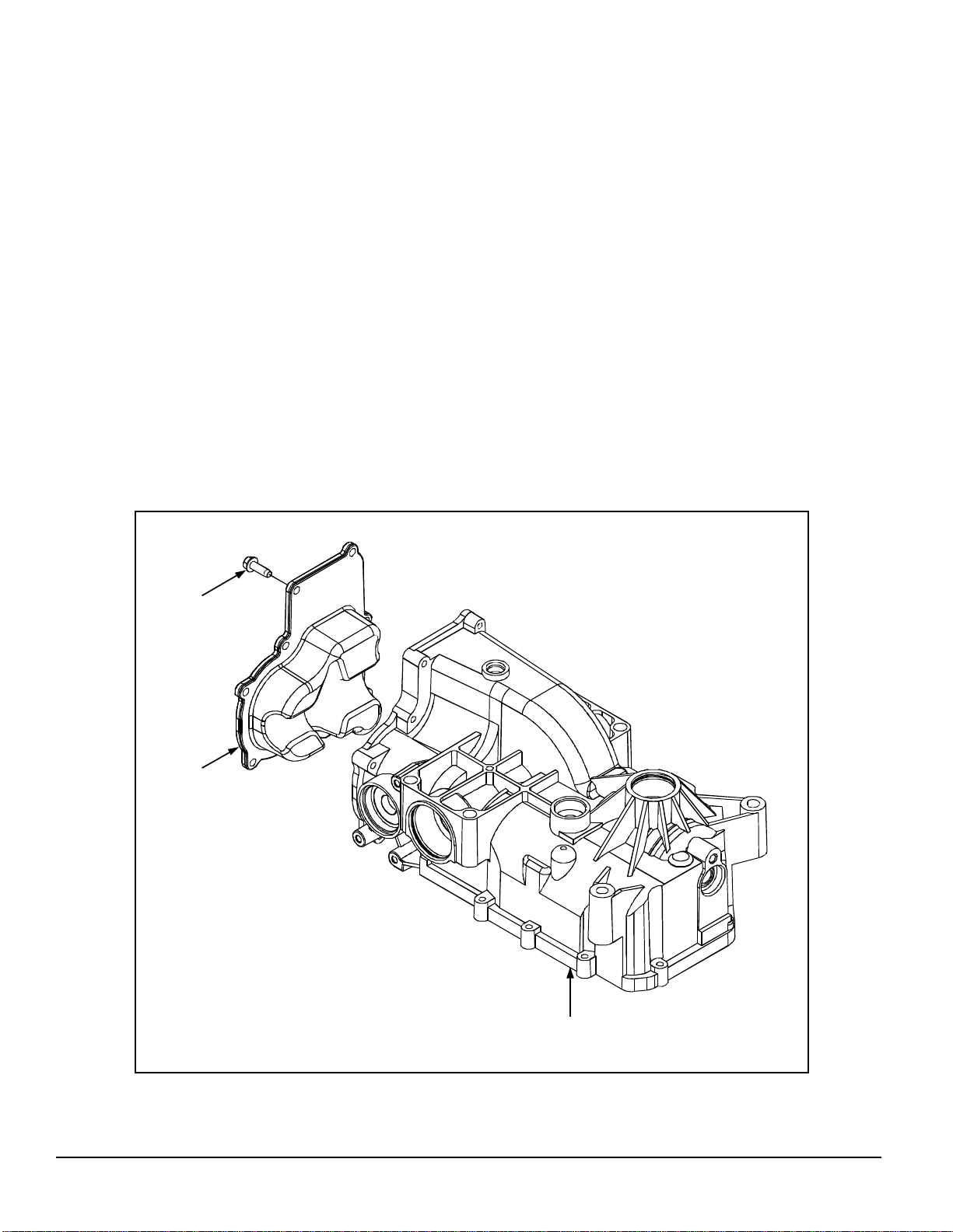
BACK COVER
Refer to Figure 8.
DISASSEMBLY
1. Remove the eight screws (50) from the back
cover (13), and discard.
2. Remove the back cover (13). Take care not
to damage the casting surfaces.
3. Clean off the sealant from the mating
surfaces of the back cover (13) and the
main housing assembly (1).
INSPECTION
1. Inspect the back cover (13) for excessive
wear or damage.
ASSEMBLY
1. Apply sealant to the back cover (1). Refer to
page 29.
2. Place the back cover (13) onto the main
housing assembly (1).
3. Install the eight replacement screws (50) to
secure the back cover (13) to the main
housing assembly (1). Tighten the eight
screws (50) to the torque value listed in
Table 5.
50
13
1
16
Figure 8. Back Cover Assembly
310-2400 IZT
www.mymowerparts.com
Page 19
For Husqvarna Parts Call 606-678-9623 or 606-561-4983
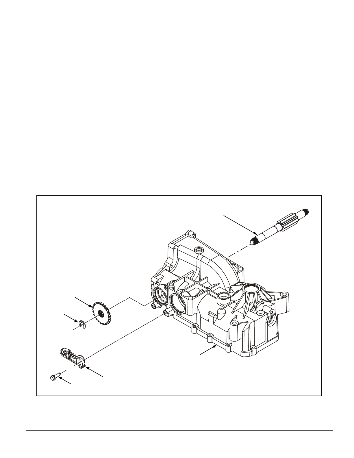
BRAKES
(Cog Brake)
Refer to Figure 9.
DISASSEMBLY
1. Remove the external retaining ring (63).
2. Remove the brake bolt (123), brake arm
(70) and brake disc (73). Note the orienta-
tion of the hub on the brake disc.
INSPECTION
1. Inspect the brake disc (73) for damaged
splines or gear teeth.
2. Inspect the brake arm (70) for damaged
teeth.
ASSEMBLY
1. Insert the brake shaft (55) into the main
housing (1). Slide the brake disc (73) onto
the brake shaft (55). Note the orientation of
the brake disc. The hub on the brake disc
should face inward on R.H. units and outward on L.H. units.
2. Install the brake arm (70) and brake bolt
(123) onto the main housing (1). Tighten the
brake bolt (123) to the torque value listed in
Table 5.
3. Install an external retaining ring (63) onto
the brake shaft (55).
55
310-2400 IZT
73
63
1
70
123
Figure 9. Cog Brake Assembly
17
www.mymowerparts.com
Page 20
For Husqvarna Parts Call 606-678-9623 or 606-561-4983
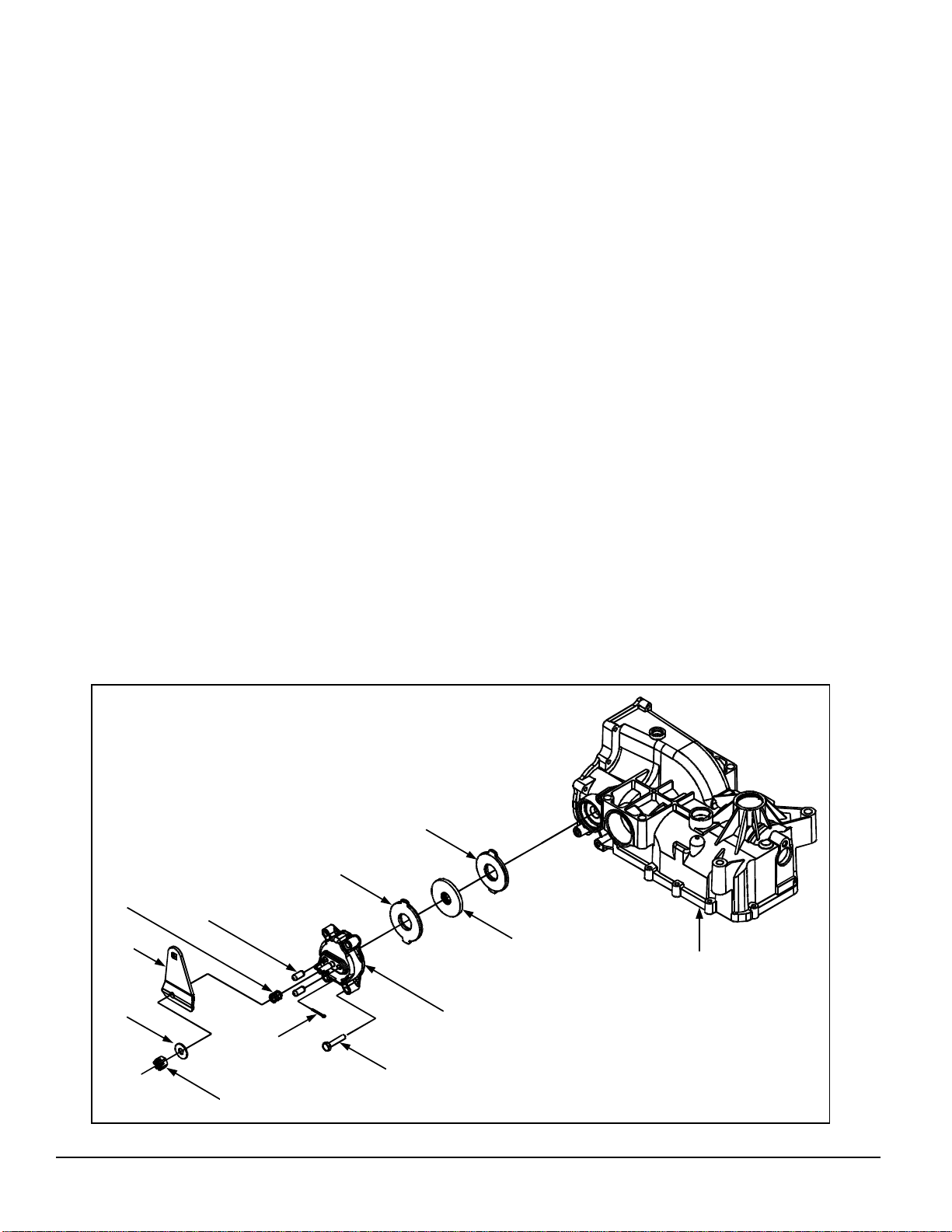
BRAKES
(Disc Brake)
Refer to Figure 10.
DISASSEMBLY
1. Remove the cotter pin (128) and slotted hex
nut (133). Discard the cotter pin.
2. Remove the washer (19), brake arm (70),
compression spring (130) and brake
actuating pins (129).
3. Remove the three brake yoke screws (123).
Remove the brake yoke (131).
4. Remove the stators (127) and rotor (73).
INSPECTION
1. Inspect the brake components for excessive
wear. Replace if necessary.
ASSEMBLY
1. Slide the stators (127) and rotor (73) onto
the brake shaft (55, Figure 11). Pay close
attention to the stack up of the stators and
rotor.
2. Install the brake yoke (131) with the three
brake yoke screws (123) onto the main
housing (1). Refer to Table 5 for the
required torque.
3. Install the brake actuating pins (129) and
compression spring (130) onto the brake
yoke (131).
4. Install the brake arm (70), washer (19) and
slotted hex nut (133) onto the brake yoke
(131). Do not tighten the slotted hex nut
(133) at this time.
5. Insert a .020" (0.5 mm) feeler gage between
the brake rotor (73) and outer stator (127).
Adjust the brake by tightening or loosening
the slotted hex nut (133).
130
70
19
6. Install a new cotter pin (128) to secure the
slotted hex nut (133).
127
127
129
73
1
131
128
123
18
133
Figure 10. Disc Brake Assembly
310-2400 IZT
www.mymowerparts.com
Page 21
For Husqvarna Parts Call 606-678-9623 or 606-561-4983
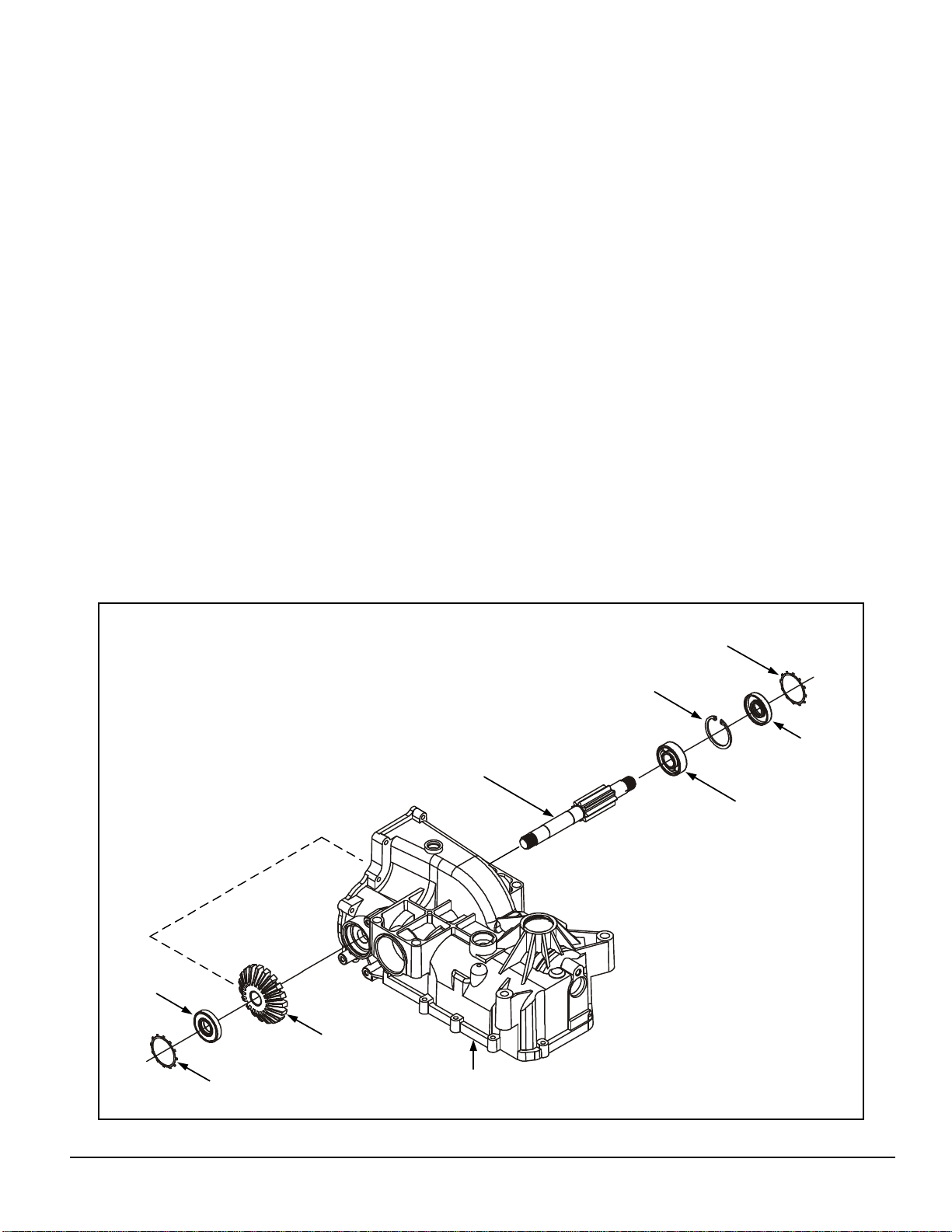
BRAKE SHAFT & BEVEL GEAR
Refer to Figure 11.
DISASSEMBLY
1. Remove the back cover. See page 16.
2. Remove the brake. See pages 17-18.
3. Remove the brake shaft lip seals (58) and
retaining rings (126). Discard the lip seals
(58).
4. Remove the retaining ring (67) from the
outside of the ball bearing (26).
5. Remove the brake shaft (55) and ball
bearing (26) from the 19 tooth bevel gear
(52). It may be necessary to tap lightly on
the brake shaft (55) to remove the bearing
(26).
6. Remove the 19 tooth bevel gear (52).
INSPECTION
1. Inspect the brake shaft (55), ball bearing
(26) and bevel gear (52) for wear or damage.
ASSEMBLY
1. Insert the brake shaft (55) and ball bearing
(26) into the main housing (1) allowing the
brake shaft (55) to pass through the 19
tooth bevel gear (52).
2. Install the retaining ring (67).
3. Install the brake shaft lip seals (58) and
retaining rings (126).
4. Install the brake. See pages 17-18.
5. Install the back cover. See page 16.
58
126
126
67
58
55
26
52
1
310-2400 IZT
Figure 11. Brake Shaft & Bevel Gear Assembly
19
www.mymowerparts.com
Page 22

For Husqvarna Parts Call 606-678-9623 or 606-561-4983
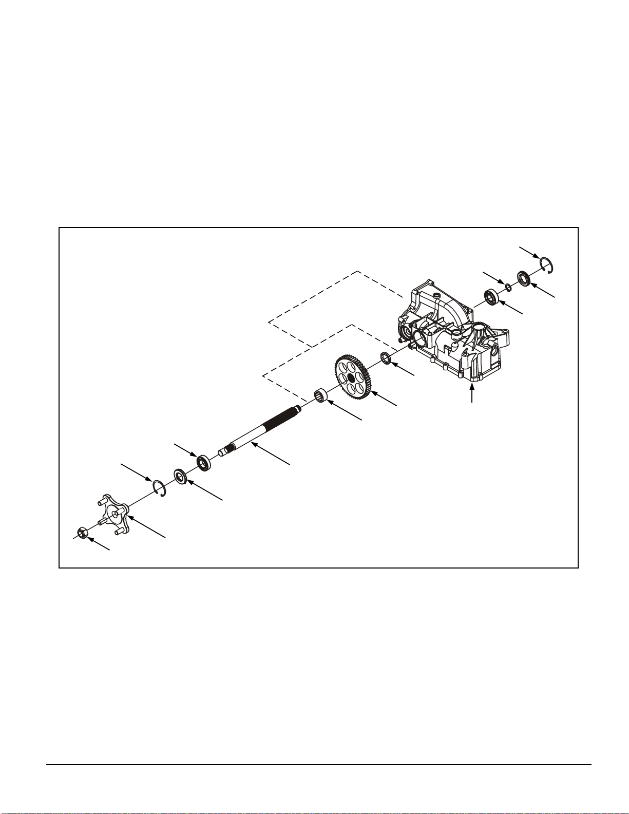
AXLE SHAFT & SPUR GEAR
Refer to Figure 12.
DISASSEMBLY
1. Remove the back cover. See page 16.
2. Remove the brake. See page 17-18.
3. Remove the brake shaft and bevel gears.
See page 19.
4. Remove the hub assembly (107), if not
already removed.
Note: The orientation of the hub and axle
to the main housing is critical in reassembly.
5. Remove the retaining ring (68) from the
outside of the axle shaft seal (66).
6. Remove the axle shaft seal (66) and
discard.
7. Remove the retaining ring (68) from the
outside of the side seal plug (60).
8. Remove the side seal plug (60) by lightly
tapping on the end of the axle shaft (56)
with a plastic or rubber mallet. Discard the
side seal plug (60).
ASSEMBLY
1. Place the spur gear (53) and axle bushings
(81&82), per noted orientation, into the main
housing (1).
2. Insert the axle shaft bearing (64) and axle
shaft (56) into the main housing (1).
(A clean screwdriver may be used to help
align the gear and bushings during
installation).
3. Place the axle retaining ring (62) onto the
end of the axle shaft (56).
4. Using a rubber or plastic mallet, lightly tap a
new side seal plug (60) into the main
housing (1). Install the seal plug retaining
ring (68).
5. Slide the axle shaft bearing (65) onto the
hub end of the axle shaft (56).
6. Slide the axle seal (66) onto the axle shaft
(56). Remember to protect the seal (66)
during installation by covering the axle shaft
(56) with cellophane. Remove the cellophane once the seal (66) is installed.
7. Install the retaining ring (68).
9. Remove the axle shaft retaining ring (62)
from the axle shaft (56).
10. Remove the axle shaft (56) from the main
housing assembly (1). Remove the ball
bearings (64 & 65) from the axle shaft (56).
Note the orientation of the axle shaft
bushings (81 & 82). This is important for
reassembly. Remove the two axle shaft
bushings (81 & 82) and spur gear (53) from
the inside of the main housing (1).
INSPECTION
1. Inspect the ball bearings (64 & 65) and axle
shaft (56) for wear or damage.
2. Inspect the spur gear (53) for wear or
damage.
20
8. Install the hub assembly (107) and nut (108)
with the bolt threads facing away from the
transaxle.
9. Install the brake shaft and bevel gear. See
page 19.
10. Install the brake. See pages 17-18.
11. Install the back cover. See page 16.
310-2400 IZT
www.mymowerparts.com
Page 23
For Husqvarna Parts Call 606-678-9623 or 606-561-4983
AXLE SHAFT & SPUR GEAR
68
62
60
64
68
108
65
107
81
53
82
56
66
Figure 12. Axle Shaft & Spur Gear Assembly
1
310-2400 IZT
21
www.mymowerparts.com
Page 24
For Husqvarna Parts Call 606-678-9623 or 606-561-4983
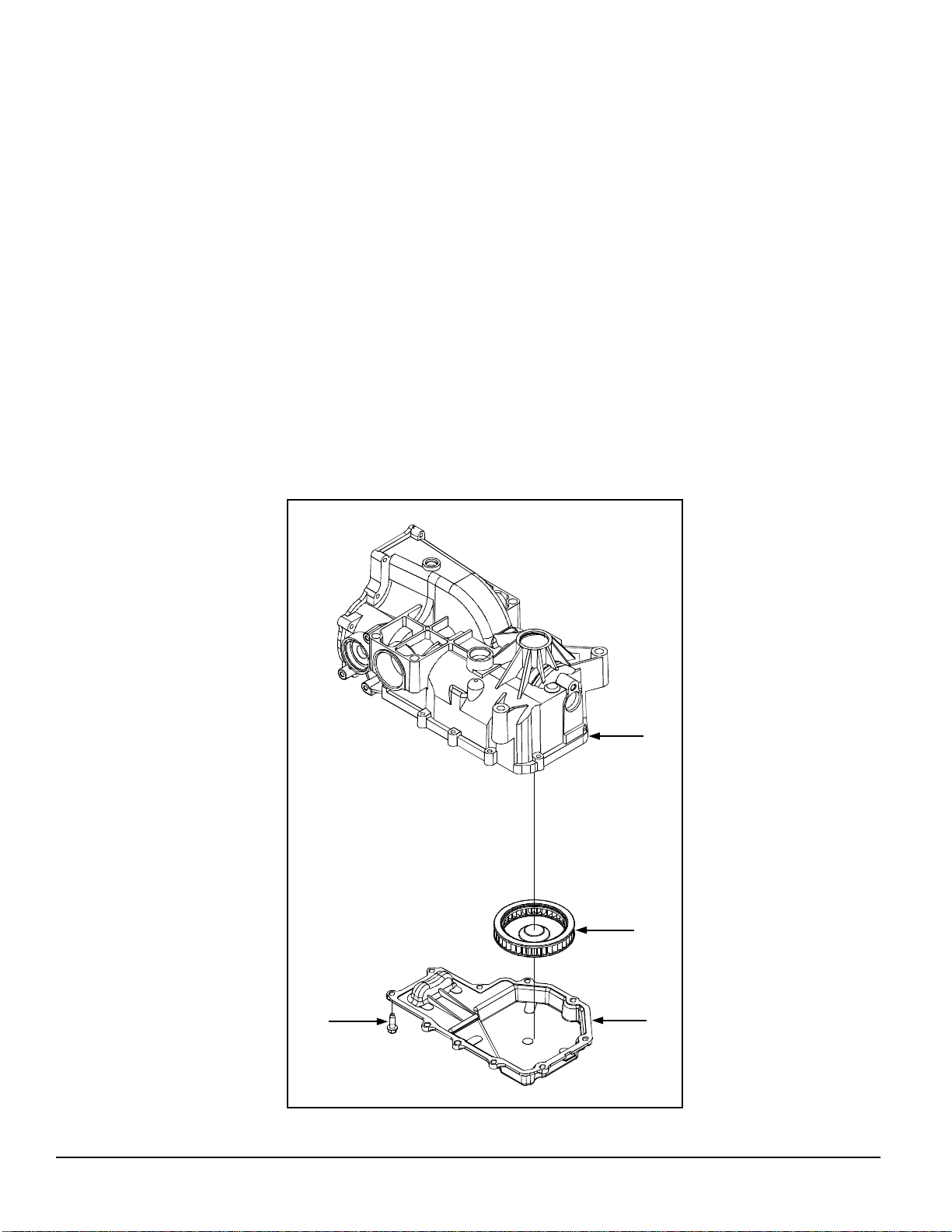
LOWER HOUSING & FILTER
Refer to Figure 13.
DISASSEMBLY
1. Remove the ten screws (50) holding the
lower housing (2) to the main housing (1),
and discard.
2. Remove the lower housing (2) and old
sealant. Take care not to damage the
casting surfaces.
3. Remove and discard the internal filter (46).
INSPECTION
1. Inspect the lower housing (2) for excessive
wear or damage.
ASSEMBLY
1. Install a new filter (46).
2. Apply sealant to the lower housing (2)
where the lower housing (2) mates with the
main housing (1). Refer to page 29.
3. Place the lower housing (2) on the main
housing (1).
4. Install the ten replacement screws (50) that
hold the lower housing (2) to the main housing (1).
5. Torque the ten screws (50) to the value
listed in Table 5.
22
50
1
46
2
Figure 13. Lower Housing & Filter
310-2400 IZT
www.mymowerparts.com
Page 25
For Husqvarna Parts Call 606-678-9623 or 606-561-4983
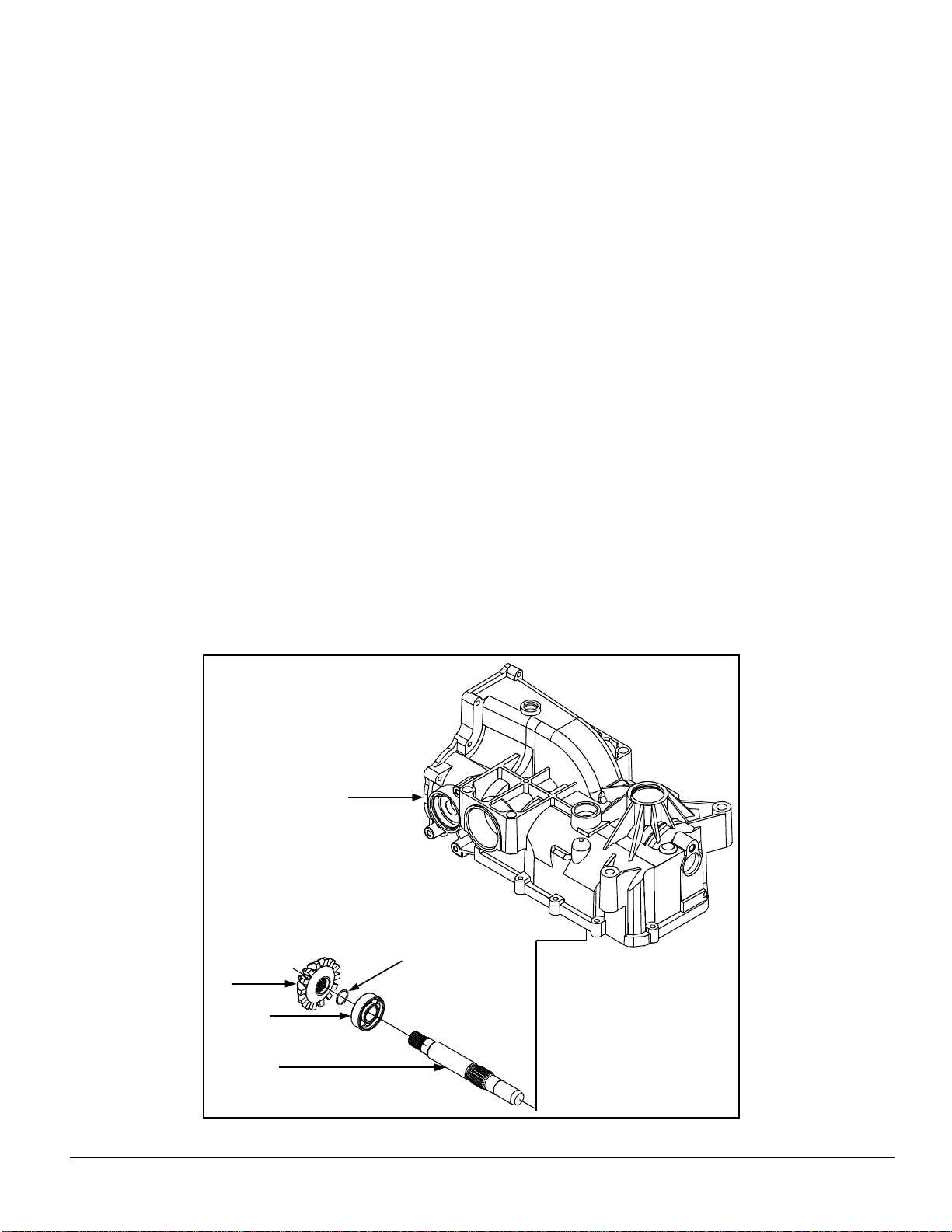
MOTOR SHAFT & BEVEL GEAR
Refer to Figure 14.
DISASSEMBLY
1. Remove the back cover. See page 16.
2. Remove the brake. See pages 17 & 18.
3. Remove the brake shaft & bevel gear.
See page 19.
4. Remove the axle shaft & spur gear.
See pages 20 & 21.
5. Remove the 14 tooth bevel gear (51) from
the motor shaft (54).
6. Remove the motor shaft (54), wire retaining
ring (27) and bearing assembly (26) from
the main housing (1). Note: The bearing
(26) does not fit flush with the housing.
This is important for reassembly.
INSPECTION
ASSEMBLY
1. Install the motor shaft (54), bearing assembly (26) and wire retaining ring (27). Note:
The splines must be aligned when inserting the motor shaft (54).
2. Install the 14 tooth bevel gear (51) on the
end of the motor shaft (54).
3. Install the axle shaft and spur gear. See
pages 20 and 21.
4. Install the brake shaft and bevel gear. See
page 19.
5. Install the brake. See pages 17 and 18.
6. Install the back cover. See page 16.
1. Inspect the gear (51), shaft (54) and bearing
(26) for wear or damage.
1
27
51
26
310-2400 IZT
54
Figure 14. Motor Shaft & Bevel Gear Assembly
23
www.mymowerparts.com
Page 26

For Husqvarna Parts Call 606-678-9623 or 606-561-4983
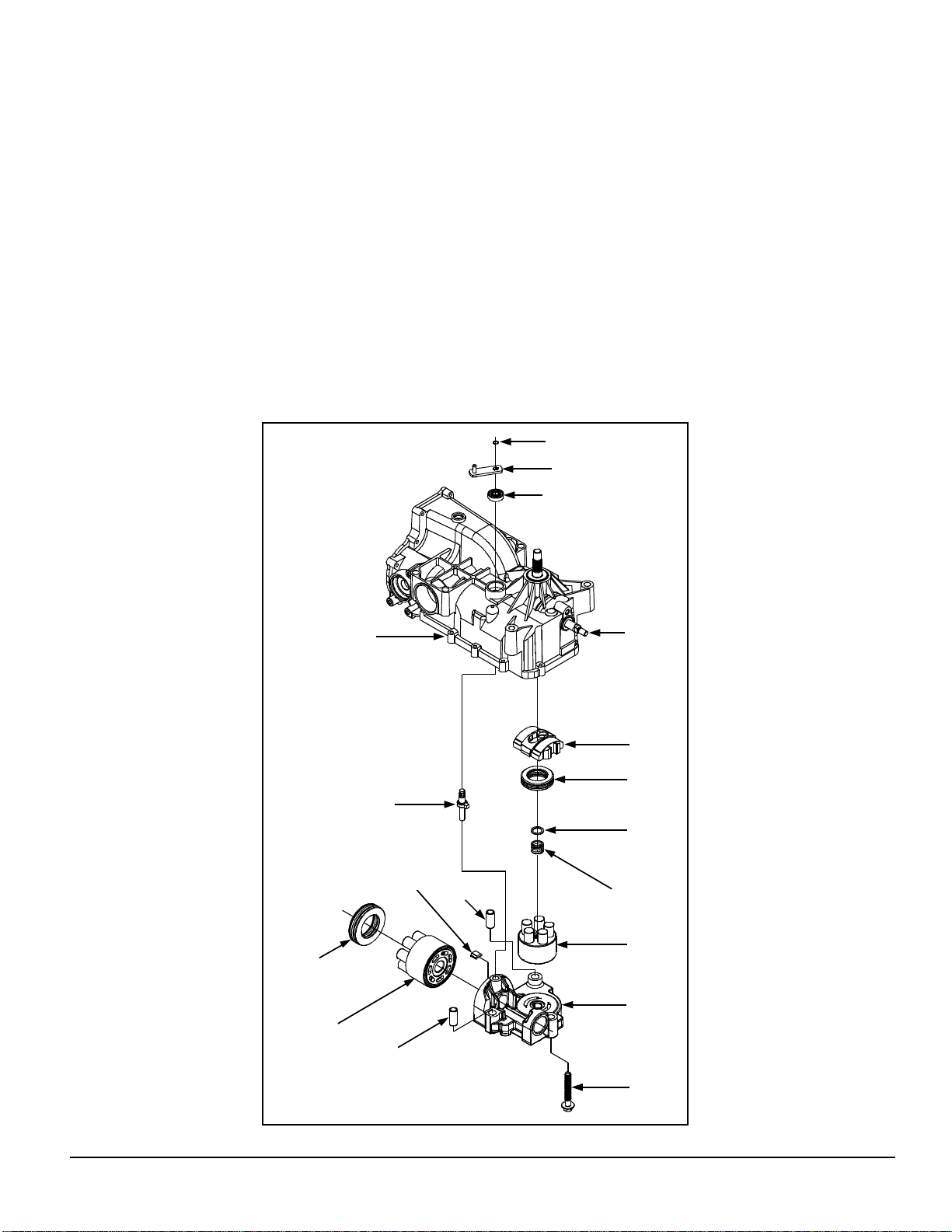
CENTER SECTION, CYLINDER BLOCKS AND BYPASS
Refer to Figure 15.
DISASSEMBLY
1. Remove the back cover. See page 16.
2. Remove the brake assembly. See pages 17
and 18.
3. Remove the brake shaft and bevel gear.
See page 19.
4. Remove the axle shaft and spur gear. See
pages 20 and 21.
5. Remove the lower housing and filter. See
page 22.
6. Remove the motor shaft and bevel gear.
See page 23.
7. Remove the three screws (44) holding the
center section (3) to the upper housing (1).
Lift to remove the center section (3) and
motor cylinder block assembly (21). Remove the two pins (43).
INSPECTION
1. Check the pistons in the motor and pump
blocks for free movement.
2. Remove and inspect the pistons, springs
and seats for wear or damage.
3. Inspect the piston bores in the cylinder
blocks for wear or damage.
4. Check the running surface of the motor and
pump cylinder blocks for damage. This surface must be smooth in the three sealing
areas. Reassemble the motor and pump
cylinder block assemblies and set aside.
5. Inspect the bushing in the center section
and the by-pass plate (38).
6. Check the motor and pump cylinder block
running surfaces on the center section (3).
This surface should be smooth. Drag a
fingernail across it to detect scratches or
smearing.
8. Remove the motor cylinder block assembly
(21).
9. Remove the motor block thrust bearing assembly (25). Note: The thick race is lo-
cated nearest to the pistons when assembled properly.
10. Remove the pump block assembly (15).
11. Remove the pump block spring (14),
washer (24) and swashplate assembly
(10).
12. Remove the thrust bearing assembly (11).
Note: The thick race is located nearest
to the pistons when assembled properly.
13. Remove the slot guide (30, Fig. 16).
14. Remove the bypass arm retaining ring (42),
bypass arm (41) and bypass lip seal (40).
Discard the lip seal.
7. Inspect the thrust bearing assemblies (11
and 25) for wear or damage.
ASSEMBLY
1. Install a new bypass lip seal (40). Install the
bypass arm (41) and retaining ring (42) onto
the bypass actuator (39).
2. Install the slot guide (30, Fig. 16).
3. Install the swashplate assembly (10)
(including the thrust bearing assembly).
Note: Install the thrust bearing assembly
(11) with the thick race towards the pistons.
4. Actuate the trunnion arm (31) and swashplate (10) to verify free movement.
5. Install the pump block washer (24) and
spring (14).
6. Install the pump block assembly (15).
7. Center the by-pass actuator (39) in the
housing pocket.
24
310-2400 IZT
www.mymowerparts.com
Page 27
For Husqvarna Parts Call 606-678-9623 or 606-561-4983
CENTER SECTION, CYLINDER BLOCKS AND BYPASS
8. Install the two pins (43).
9. Install the by-pass plate (38) into the center
section (3). Install the center section (3) and
motor cylinder block assembly (21).
10.Install the three screws (44) that hold the
center section (3) in place.
11.Install the thrust bearing assembly (25).
Note: Install the thrust bearing assembly
with the thick race towards the pistons.
12. Install the motor shaft and bevel gear. See
page 23.
13. Install the filter and lower housing. See
page 22.
14. Install the axle shaft and spur gear. See
pages 20 and 21.
15. Install the brake shaft and bevel gear. See
page 19.
16. Install the brake. See pages 17 and 18.
17. Install the back cover. See page 16.
42
41
40
25
21
1
39
43
38
43
31
10
11
24
14
15
3
310-2400 IZT
44
Figure 15. Center Section, Cylinder Blocks and Bypass
25
www.mymowerparts.com
Page 28

For Husqvarna Parts Call 606-678-9623 or 606-561-4983
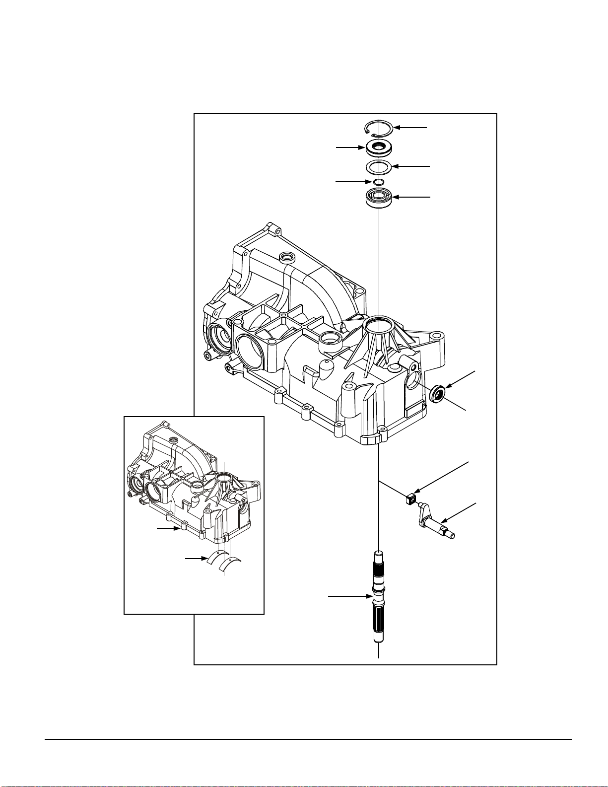
INPUT SHAFT & TRUNNION ARM
Refer to Figure 16.
DISASSEMBLY
1. Remove the back cover. See page 16.
2. Remove the brakes. See pages 17 and 18.
3. Remove the brake shaft and bevel gear.
See page 19.
4. Remove the axle shaft and spur gear. See
pages 20 and 21.
5. Remove the lower housing and filter. See
page 22.
6. Remove the motor shaft and bevel gear.
See page 23.
7. Remove the center section and cylinder
block assemblies. See pages 24 and 25.
8. Remove the input shaft retaining ring (7).
ASSEMBLY
1. Install the trunni on arm (31) if removed and
install a new trunnion seal (33).
2. Install the slot guide (30).
3. Install the input shaft (12), bearing assembly (8) and wire retaining ring (6), if removed.
4. Install the spacer (5).
5. Install a new input shaft lip seal (4). Remember to protect the seal during installation by covering the shaft with cellophane.
6. Install the input shaft retaining ring (7).
7. Install the center section and cylinder block
assemblies. See pages 24 and 25.
8. Install the motor shaft and bevel gear. See
page 23.
9. Remove and discard the lip seal (4).
10. Remove the spacer (5).
11. Remove the input shaft (12) and bearing
(8).
12. Remove the slot guide (30).
13. Rotate the trunnion arm (31) to check for
free movement.
14. Remove the trunnion shaft seal (33) if
necessary and remove the trunnion arm
(31).
INSPECTION
1. Inspect the input shaft (12) and bearing (8)
for wear or damage.
2. Inspect the slot guide (30).
3. Inspect the trunnion arm (31) for wear or
damage.
9. Install the lower housing and filter. See
page 22.
10. Install the axle shaft and spur gear. See
pages 20 and 21.
11. Install the brake shaft and bevel gear. See
page 19.
12. Install the brakes. See pages 17 and 18.
13. Install the back cover. See page 16.
4. Inspect the non-removable cradle bearings
(9) in the main housing (1) for excessive
wear.
26
www.mymowerparts.com
310-2400 IZT
Page 29
For Husqvarna Parts Call 606-678-9623 or 606-561-4983
INPUT SHAFT & TRUNNION ARM
7
4
5
6
8
1
9
Note: Cradle bearings are non-
removable. Shown removed for
illustration purposes only.
33
30
31
12
310-2400 IZT
Figure 16. Input Shaft and Trunnion Arm Assembly
27
www.mymowerparts.com
Page 30

For Husqvarna Parts Call 606-678-9623 or 606-561-4983
TRANSAXLE INSTALLATION
Use the following procedure to complete the installation of the transaxle on the vehicle.
1. Install and secure the transaxle on the
vehicle according to the instructions in the
vehicle owner’s manual.
2. Install the hub assembly (107, page 21) if
not already done. Install the ¾-16 hex nut
(108, page 21).
3. With the vehicle raised, install the wheel on
the hub, and snug the wheel lug nuts.
4. Lower the vehicle wheels to the ground and
torque the ¾-16 hex nut to 200-295 ft.-lbs.
(271-400 Nm).
5. Tighten the wheel lug nuts per the vehicle
owner’s manual.
ASSEMBLY AFTER A COMPLETE
TEARDOWN
If the unit has been torn down completely, the
following summary identifies the assembly procedures necessary to completely assemble the
unit. Each assembly procedure is located by a
page reference.
The part reference numbers provided in each
assembly procedure are keyed to the individual
exploded views, and are also keyed to the
complete unit exploded view on page 30.
1. Install the input shaft and trunnion arm. See
page 26.
2. Install the center section, motor and pump
cylinder blocks. See page 24.
3. Install the motor shaft and bevel gear. See
page 23.
4. Install the filter and lower housing. See
page 22.
5. Install the axle shaft and spur gear. See
page 20-21.
6. Install the brake shaft and bevel gear. See
page 19.
7. Install the brake. See pages 17 and 18.
8. Install the back cover. See page 16.
9. Fill the transaxle with 79 fluid ounces
(2336 ml.) of new 20w50 motor oil. This
should put the oil level approximately
1?" (48 mm) from the top of the housing.
This should be checked at the fill port.
10. Install the transaxle onto the vehicle.
11. Perform the purge procedures listed on
page 11.
12. Perform the return to neutral procedure on
page 12.
28
310-2400 IZT
www.mymowerparts.com
Page 31
For Husqvarna Parts Call 606-678-9623 or 606-561-4983
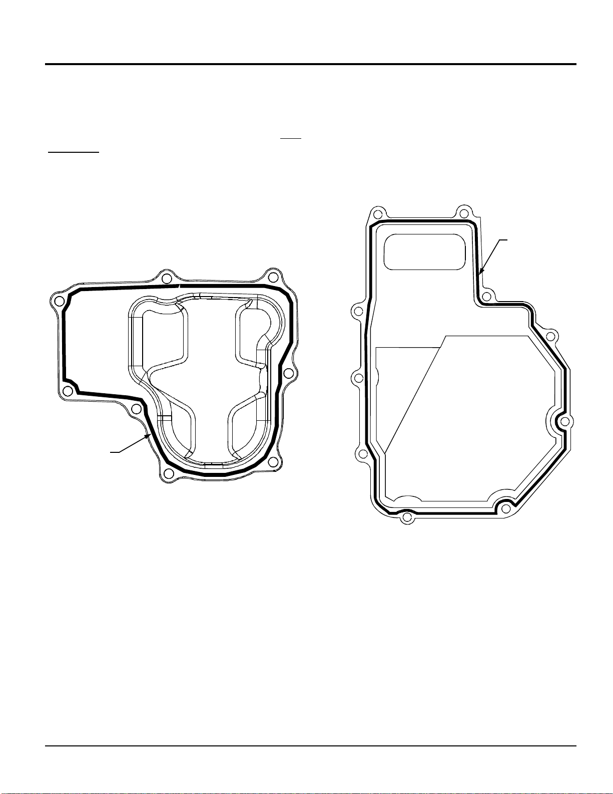
SEALANT APPLICATION
NOTE: Prior to applying the new sealant, the
old sealant must be removed from all surfaces.
A small bead of the sealant around the outer
part of the housing face will be sufficient. Use
sparingly.
The illustrations below indicate the correct
areas.
Sealant Path
Sealant Path
Back Cover Sealant Path
Lower Housing Sealant Path
310-2400 IZT
29
www.mymowerparts.com
Page 32
30
www.mymowerparts.com
50 (8X)
100
55
52
58
126
25
THICK RACE
TOWARD PISTONS
42
41
40
99
13
THICK RACE
TOWARD PISTONS
51
27
26
54
21
11
43
310-2400 IZT
100
137
1
39
38
10
43
12
24
14
15
6
8
5
30
3
49
135
136
120
7
4
31
46
127
67
26
33
121
44 (3X)
2
58
73
126
36
127
76
213
214
129
131
37
211
212
35
133
70
19
130
129
123
128
34
37
71
63
73
64
62
60
68
19
122
119
19
80—20W-50 OIL
INCLUDES ITEMS 4, 7, 33, 40, 42,
50, 58, 60, 62, 66, 67, 68 AND 126
134—SEAL KIT
215
35
82
19
105
208
209
123
53
215
56
81
207
19
216
35
56
107
65
66
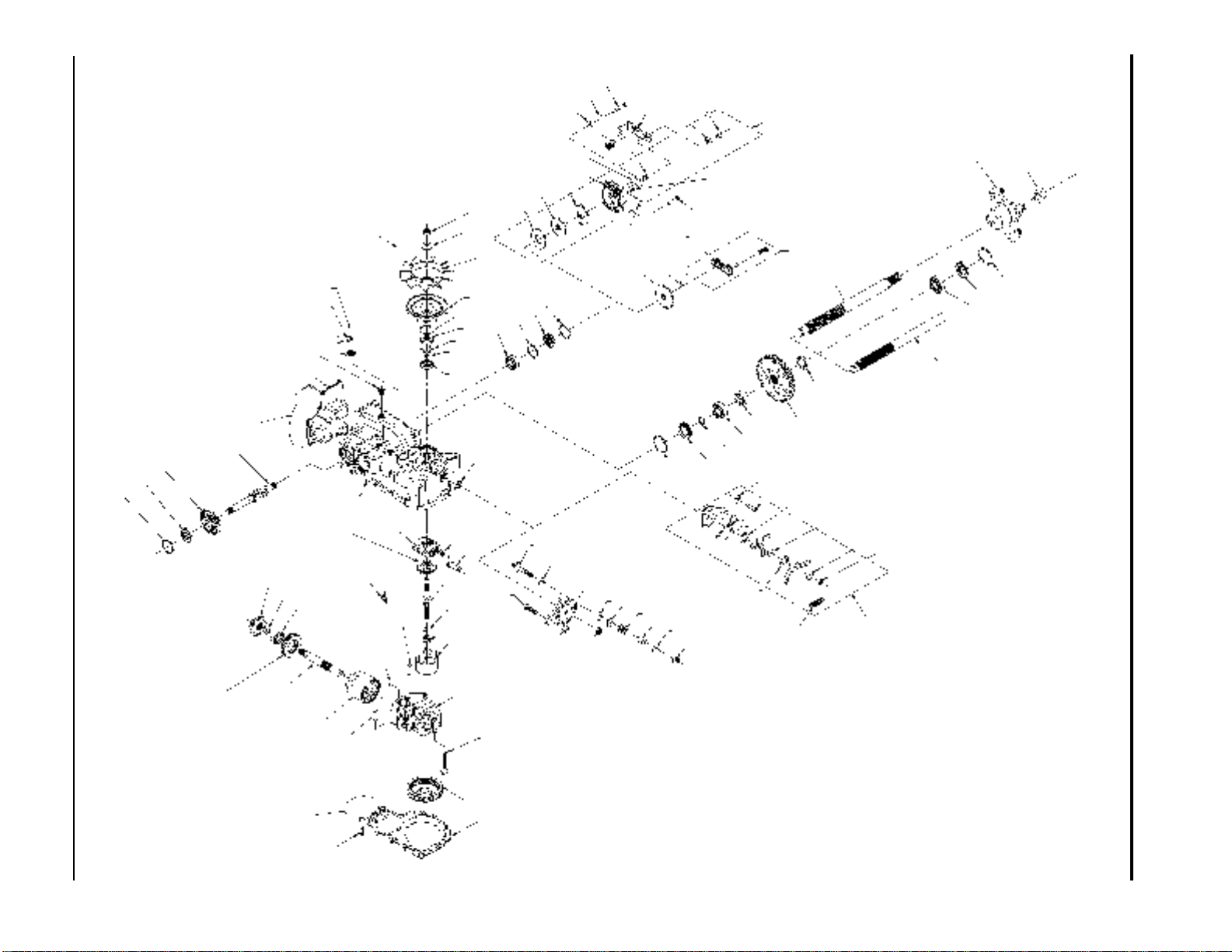
310-2400 EXPLODED VIEW
For Husqvarna Parts Call 606-678-9623 or 606-561-4983
108
68
50 (10X)
Page 33
For Husqvarna Parts Call 606-678-9623 or 606-561-4983
ITEMS LIST
No. DESCRIPTION No. DESCRIPTION
1 Kit, Housing-Main
Housing, Main
Cradle Bearing
Lip Seal
Trunnion Bushing
2 Lower Housing
3 Center Section Assembly Kit
Bypass Plate
Check Plug Assembly
Center Section
Bushing
Screw
4 Lip Seal
5 Spacer
6 Wire Retaining Ring
7 Retaining Ring
8 Ball Bearing
9 Cradle Bearing
10 Variable Swashplate
11 Thrust Bearing 30 X 52 X 13
12 Input Shaft
13 Cover-Back
14 Spring, Block
15 10cc Cylinder Block Assy
10cc Cylinder Block
10cc Piston Spring
Piston Seat Washer
10cc Piston
19 Washer
21 21cc Cylinder Block Assy
21cc Cylinder Block
21cc Piston Spring
Piston Seat Washer
21cc Piston
24 Washer, Block Thrust
25 Thrust Bearing 42 X 68 X 16
26 Ball Bearing
27 Wire Retaining Ring
30 Slot Guide
31 Trunnion Arm
33 Lip Seal
34 RTN Control Arm
Standard Control Arm
35 RTN Hex Lock Nut, 5/16-24 UNJF (Nylon Insert)
Standard Control Arm Nut
36 Stud-Long 5/16-24
37 Friction Puck
38 Bypass Plate
39 Bypass Actuator
40 Lip Seal
41 Bypass Arm
42 Retaining Ring
43 Pin
44 Screw
46 Filter
49 Hex Lock Nut 1/2-20 (Nylon Insert)
50 Screw, 1/4-20 X .75 Long
51 14T Bevel Gear
52 19T Bevel Gear
53 53T Spur Gear
54 Motor Shaft
55 Brake Shaft
56 Shaft, Axle 25mm X 14 (D,D)
Axle Shaft
58 Seal, Lip 17 X 40 X 7
60 Seal Plug - Side
62 Retaining Ring - Axle
63 Retaining Ring Kit
64 Bearing-Ball 20 X 47 X 14 (6204)
65 Bearing-Ball 20 X 47 X 12 (6205)
66 Seal
67 Retaining Ring
68 Retaining Ring-Axle
70 Arm, Brake
71 RH, Brake Arm Service Assy
Brake Arm
Clevis Pin
Bushing 0.255 X 0.381 X 0.330
Hex Washer Head Screw, 1/4-20 X 7/8
73 Disc Brake Yoke Brake Rotor
Cog Brake Arm Brake Disc
310-2400 IZT
76 Hex Nut 5/16-18
80 20W-50 Oil
81 Axle Bushing
82 Axle Bushing
99 Plastic Plug
100 Sealant
105 Kit, Brake
Washer
Rotor, Brake
Stator, Brake Friction
Cotter Pin 3/32 X 3/4
Brake Actuating Pin
Compression Spring Anti Drag
Kit, Yoke-Brake
107 Hub Assembly
Hub
Lug Bolt
108 Nut, Hex 3/4-18
110 Fitting O-Ring Assembly
Pastic Hose Fitting
O-Ring
111 Cap Vent Assembly
Cap-Poppet Valve
Plastic Vent
119 Spacer
120 Pulley, 4.5
121 Bolt 5/16-18 X 1-1/4
122 Helical Comp. Spring
123 Disc Brake Yoke Screw, 1/4-28 X 1.38 W/Patch
Cog Brake Arm Hex Washer Head Screw, 1/4-20 X 7/8
126 Ring Retaining
127 Stator, Brake Friction
128 Cotter Pin 3/32 X 3/4
129 Brake Actuating Pin
130 Compression Spring Brake Anti Drag
131 Kit, Yoke-Brake
Sq Hd Bolt 5/16-24 Ribbed
Yoke, Brake
133 Slotted Hex Nut 5/16-24
134 Kit, Seal
Seal, Lip 15 X35 X 7
Ring, Retaining
Seal, Lip 12 X 25 X 7
Seal, Lip 10 X 25 X 7
Ring, Retaining
Seal, Lip 17 X 40 X 7
Seal, Lip 1.85 X 32
Ring, Retaining
Ring, Retaining .440 External
Seal, Lip .98 X 1.85 X .276
Ring, Retaining
Ring, Retaining
Ring, Retaining
Seal, Lip 17 X 40 X 5
Screw, 1/4-20 X .75 Long
135 Washer, .531 X 1.250 X .092 (Bellevile)
136 Fan, 6”, 10 Blade
137 Kit, Fan-Pulley
Washer, .531 X 1.250 X .092 (Belleville)
Fan, 6”, 10 Blade
Hex Lock Nut 1/2-20 (Nylon Insert)
Pulley, 4.5
207 Spacer, RTN
208 Screw, 5/16-24 X .75 (Patch)
209 Spring, Extension
211 Screw, Hex Head 1/4-28 X 1.75 W/Patch
212 Spring, Brake Arm Bias
213 Washer, Flat .28 X .73 X .063
214 Brake Assy. Spacer
215 Washer, Nylon
216 RTN, Kit
Washer
Hex Lock Nut, 5/16-24 UNJF (Nylon Insert)
Spacer, RTN
Screw, 5/16-24 X .75 (Patch)
Spring, Extension
Washer, Nylon
Control Arm
Arm, RTN Scissor, Outer
Arm, RTN Scissor, Inner
Arm, Return
31
www.mymowerparts.com
Page 34

For Husqvarna Parts Call 606-678-9623 or 606-561-4983
GLOSSARY OF TERMS
Axial Piston: Type of design for hydraulic motors and pumps in which the pistons are arranged
parallel with the spindle (input or output shaft).
Bantam Duty: A descriptive term relating to the product capacity (meaning: light duty).
Bypass Valve: A valve whose primary function is to open a path for the fluid to bypass the motor
or pump. Also referred to occasionally as the freewheel valve or dump valve.
Case Drain Line (Return Line): A line returning fluid from the component housing to the
reservoir.
Cavitation: A concentrated gaseous condition within the fluid causing the rapid implosion of a
gaseous bubble.
Center Section: A device which acts as the valve body and manifold of the transmission.
Charge Pump: A device which supplies replenishing fluid to the fluid power system (closed loop).
Charge Pressure: The pressure at which replenishing fluid is forced into a fluid power system.
Charge Relief Valve: A pressure control valve whose primary function is to limit pressure in the
charge circuit.
Check Valve: A valve whose primary function is to restrict flow in one direction.
Closed Loop: A sealed and uninterrupted circulating path for fluid flow from the pump to the motor
and back.
Decay Rate: The ratio of pressure decay over time.
End Cap: See “Center Section”
Entrained Air: A mechanical mixture of air bubbles having a tendency to separate from the liquid
phase.
Gerotor: A positive displacement pump frequently used as a charge pump.
Hydraulic Motor: A device which converts hydraulic fluid power into mechanical force and motion
by transfer of flow under pressure.
Hydraulic Pump: A device which converts mechanical force and motion into hydraulic fluid power
by producing flow.
Hydrostatic Pump: See “Hydraulic Pump”
32
310-2400 IZT
www.mymowerparts.com
Page 35

For Husqvarna Parts Call 606-678-9623 or 606-561-4983
GLOSSARY OF TERMS
Hydrostatic Transaxle: A multi-component assembly including a gear case and a hydrostatic
transmission.
Hydrostatic Transmission: The combination of a hydraulic pump and motor in one housing to
form a device for the control and transference of power.
Inlet Line: A supply line to the pump.
Integrated Hydrostatic Transaxle (IHT): The combination of a hydrostatic transmission and gear
case in one housing to form a complete transaxle.
Manifold: A conductor which provides multiple connection ports.
Neutral: Typically described as a condition in which fluid flow and system pressure is below that
which is required to turn the output shaft of the motor.
Pressure Decay: A falling pressure.
Priming: The filling of the charge circuit and closed loop of the fluid power system during start up,
frequently achieved by pressurizing the fluid in the inlet line.
Purging: The act of replacing air with fluid in a fluid power system by forcing fluid into all of the
components and allowing the air a path of escape.
Rated Flow: The maximum flow that the power supply system is capable of maintaining at a spe-
cific operating pressure.
Scoring: Scratches in the direction of motion of mechanical parts caused by abrasive contami-
nants.
Swash Plate: A mechanical device used to control the displacement of the pump pistons in a fluid
power system.
System Charge Check Valve: A valve controlling the replenishing flow of fluid from a charge cir-
cuit to the closed loop in a fluid power system.
System Pressure: The pressure which overcomes the total resistance in a system, including all
losses.
Valve: A device which controls fluid flow direction, pressure, or flow rate.
Variable Displacement Pump: A pump in which the displacement per cycle can be varied.
Volumetric Displacement: The volume for one revolution.
310-2400 IZT
33
www.mymowerparts.com
Page 36

For Husqvarna Parts Call 606-678-9623 or 606-561-4983
© 2001 HYDRO-GEAR
Printed in U.S.A.
34
310-2400 IZT
www.mymowerparts.com
 Loading...