

Page 1

For Husqvarna Parts Call 606-678-9623 or 606-561-4983
357XP/359
www.mymowerparts.com
Workshop Man ual
101 91 17-26
Page 2

For Husqvarna Parts Call 606-678-9623 or 606-561-4983
Workshop manual
Husqvarna 357XP/G and 359/G
Contents
Introduction ...........................................................2
Safety regulations ................................................. 3
General instructions ...........................................3
Special instructions ............................................3
Special tools .......................................................... 4
Technical data .......................................................6
Construction and function ...................................8
Carburettor.........................................................8
Troubleshooting..................................................10
Repair instructions ............................................. 12
Chain brake......................................................12
Silencer ............................................................14
Chain catcher...................................................14
Stop switch.......................................................15
Stop switch – resistance measurement ........... 15
Choke control...................................................16
Throttle trigger..................................................17
Hand grip heater .............................................. 18
Starter assembly ..............................................20
Starter cord ...................................................... 21
Recoil spring .................................................... 21
Ignition module – testing ..................................22
Ignition module and flywheel............................22
Generator.........................................................23
Centrifugal clutch ............................................. 25
Oil pump...........................................................27
Carburettor.......................................................29
Carburettor – pressure testing ......................... 32
Carburettor – adjustment ................................. 36
Fuel tank .......................................................... 37
Fuel filter .......................................................... 38
Fuel hose ......................................................... 38
Piston and cylinder...........................................40
Decompression valve – pressure testing .........41
Cylinder – pressure testing .............................. 43
Crankcase and crankshaft ............................... 43
Crankshaft bearings.........................................44
Repairing damaged threads.............................46
Guide bar bolts.................................................46
Appendix A, Carburettor – EPA models ........... 47
www.mymowerparts.com
English – 1
Page 3

For Husqvarna Parts Call 606-678-9623 or 606-561-4983
Introduction
Arrangement of the manual
This workshop manual can be used in two different
ways.
• To repair a specific sub-assembly on a chainsaw.
• To dismantle and reassemble a complete
chainsaw.
Repairing a specific sub-assembly
If a specific sub-assembly on the chainsaw needs
to be repaired:
1. Look up the page referring to the relevant subassembly.
2. Follow the instructions under the headings:
Removal/Dismantling
Cleaning and inspection
Refitting/Reassembly
Dismantling and reassembling the entire
chainsaw
If the entire chainsaw is to be dismantled, follow
the instructions under the heading “Removal/
Dismantling”.
Troubleshooting
These pages describe the most common faults that
affect a chainsaw. They are divided into four
different groups with the most likely faults described first.
Repair instructions
The section that describes how to repair the
chainsaw consists of detailed, step-by-step instructions. It explains in detail the special tools, lubricants and bolt torques that are needed when
working on each component.
This workshop manual covers the following
chainsaw models:
357XP/G
359/G
Work through the manual and follow the instructions given in each section under the heading
“Removal/Dismantling”.
Then follow all the “Cleaning and inspection”
instructions in each section.
Working from the back of the manual, follow all the
instructions under the headings “Refitting/
Reassembly” in reverse order.
Each of the sections covering removal/dismantling
and refitting/reassembly include the relevant
lubrication instructions and bolt torques for each
stage of repair.
Construction and function
This chapter gives a simple description of the
chainsaw carburettor and its various parts.
2 – English
www.mymowerparts.com
Page 4

For Husqvarna Parts Call 606-678-9623 or 606-561-4983
Safety regulations
General instructions
This workshop manual gives detailed instructions
on how to troubleshoot, repair and test a chainsaw.
This section also describes the various safety
precautions that should be taken when carrying out
repairs.
The workshop manual has been written for personnel who are assumed to have general experience
of repairing and servicing chainsaws.
Workshops where chainsaws are repaired must be
equipped with safety equipment that meets local
regulations.
No-one should carry out repairs on a chainsaw
until they have read and understood the contents
of this workshop manual.
Chainsaws are type-approved to meet the relevant
safety legislation, but this only applies when the
saw is fitted with the cutting equipment specified in
the user’s manual. The fitting of any other equipment, or of accessories or parts that are not
approved by Jonsered, could mean that the saw no
longer meets these safety requirements and the
person who carried out the work may be held
responsible for its non-conformance.
Special instructions
The fuel that is used in a chainsaw poses the
following hazards:
• The fuel and its fumes are toxic.
• May cause irritation to skin or eyes.
• May cause breathing difficulties.
• Highly flammable.
When using compressed air the air jet should
never be pointed at the body. Air can be forced into
the bloodstream and cause fatal injury.
Wear ear protection when testing saws.
After testing a saw do not touch the silencer until it
has cooled down. The silencer gets very hot and
you may burn yourself. Wear protective gloves
when working on the silencer.
The guide bar, chain and clutch cover (chain brake)
must be fitted before the saw is started. If not, the
clutch may come loose and cause injury.
Poor chain lubrication can result in failure of the
chain, which could cause serious or fatal injury.
In this workshop manual the following boxes
indicate where caution should be taken.
WARNING!
The warning text warns of the risk
of personal injury if the instructions are not followed.
NOTE!
The warning text warns of the risk of
material damage if the instructions are
not followed.
Take care to ensure that the spring inside the
starter assembly does not fly out and cause injury.
Wear eye protection. If the spring is under compression when the pulley is removed it could fly out
and cause injury.
Before removing the tensioning spring from the
chain brake, ensure that the brake is in the on
position, otherwise the spring may fly out and
cause injury.
After repair, the chain brake must be checked as
described in the section “Chain brake – operating
test”.
Always consider the fire risk. A chainsaw can
produce sparks that could start a fire.
Inspect the chain catcher and replace it if it is
damaged.
www.mymowerparts.com
English – 3
Page 5
For Husqvarna Parts Call 606-678-9623 or 606-561-4983
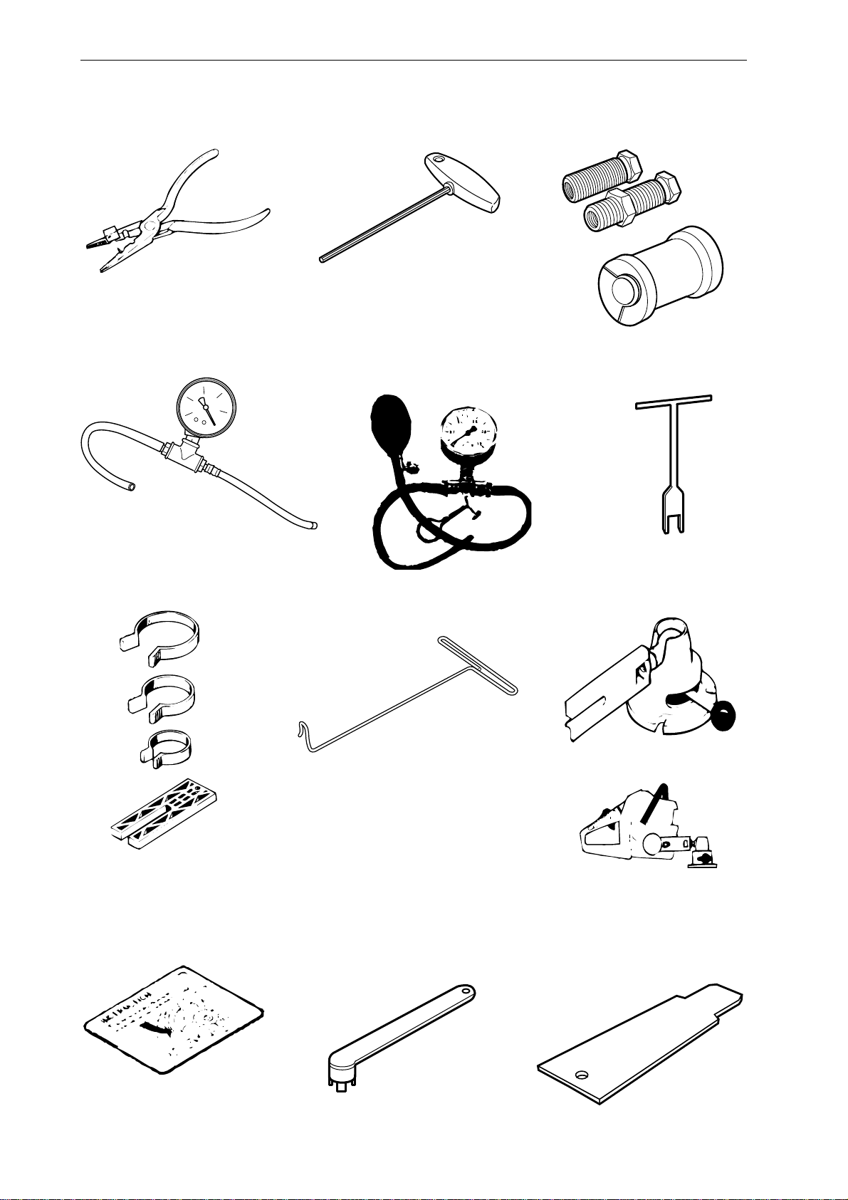
Special tools
1
4
2
5
3
6
7
8
1110
9
12
4 – English
www.mymowerparts.com
Page 6

For Husqvarna Parts Call 606-678-9623 or 606-561-4983
Special tools
13
14
16 17
15
18
Item Description Used for Order no.
1 Assembly pliers Fitting spark plug guard 502 50 06-01
2 Allen key For M5 bolts 502 50 18-01
3 Crankshaft tool Fitting crankshaft seal 502 50 30-16
4 V acuum gauge Vacuum test 502 50 37-01
5 Pressure gauge Pressurisation during testing 502 50 38-01
6 Fork Fitting clutch spring 502 50 67-01
7 Piston fitting kit Fitting piston 502 50 70-01
8 Fuel filter hook Withdrawing the fuel 502 50 83-01
9 Clamp stand Clamping the saw 502 51 02-01
10 Feeler gauge Adjusting ignition module 502 51 34-02
11 Clutch tool Centrifugal clutch 502 52 22-02
12 Cover plate Sealing during pressure testing 502 54 11-02
13 Piston stop Locking crankshaft 502 54 15-01
14 Stop plate Locating intake gaiter 502 54 17-01
15 Test plug Checking ignition module 502 71 13-01
16 Rev counter Adjusting carburettor 502 71 14-01
17 Pressure tester Connection to cylinder 503 84 40-02
18 Puller Frame bearing 504 90 90-02
www.mymowerparts.com
English – 5
Page 7

For Husqvarna Parts Call 606-678-9623 or 606-561-4983
Technical data
Displacement Cylinder bore Stroke Max power/speed
cm3/cubic inches Ø mm/Ø inches mm/inches kW/hp/rpm
357XP: 57 / 3,5 46,0 / 1,81 34,0 / 1,34 3,2 / 9 600
359: 59 / 3,6 47,0 / 1,85 34,0 / 1,34 2,9 / 9 000
Spark plug gap Ignition system Air gap Carburettor type
mm/inches mm/inches
357XP: 0,5 / 0,02 FHP ET 0,3 / 0,012 Walbro HDA 174
(EPA) Walbro HDA 175
359: 0,5 / 0,02 FHP ET 0,3 / 0,012 Walbro HDA 174
(EPA) Walbro HDA 175
Effective cutting length Chain speed at Chain pitch Drive link
cm/inches max power – revs mm/inches mm/inches
m/s – rpm
357XP: 33-61 / 13-24 21,4 / 9 600 8,25 / 0,325/ 9,52/3/8 1,5 / 0,058
359: 31-58 / 13-24 20,1 / 9 000 8,25 / 0,325/ 9,52/3/8 1,5 / 0,058
6 – English
www.mymowerparts.com
Page 8

For Husqvarna Parts Call 606-678-9623 or 606-561-4983
Technical data
rpm
Idling speed Engagement speed Max. speed Spark plug
rpm rpm rpm
357XP: 2 700 3 800 14 000 Bosch RCJ 7Y, NGK BPMR 7A
359: 2 700 3 800 13 500 Bosch RCJ 7Y, NGK BPMR 7A
GAS
Fuel tank capacity Oil pump capacity at Oil tank capacity Automatic oil pump
Litres/US pints 8,500 rpm, Litres/US pints
ml/min
357XP: 0,68 / 1,44 5 - 15 0,38 / 0,80 Yes
359: 0,68 / 1,44 5 - 15 0,38 / 0,80 Yes
Weight without bar and chain Weight with bar and chain Heated hand grips
kg / lbs kg / lbs
OIL
357XP: 5,5 / 12,1 6,3 / 13,9 357XPG: 5,6 / 12,4 6,4 / 14,1 Yes
359: 5,5 / 12,1 6,3 / 13,9 359G: 5,6 / 12,4 6,4 / 14,1 Yes
www.mymowerparts.com
English – 7
Page 9
For Husqvarna Parts Call 606-678-9623 or 606-561-4983
Construction and function
Carburettor
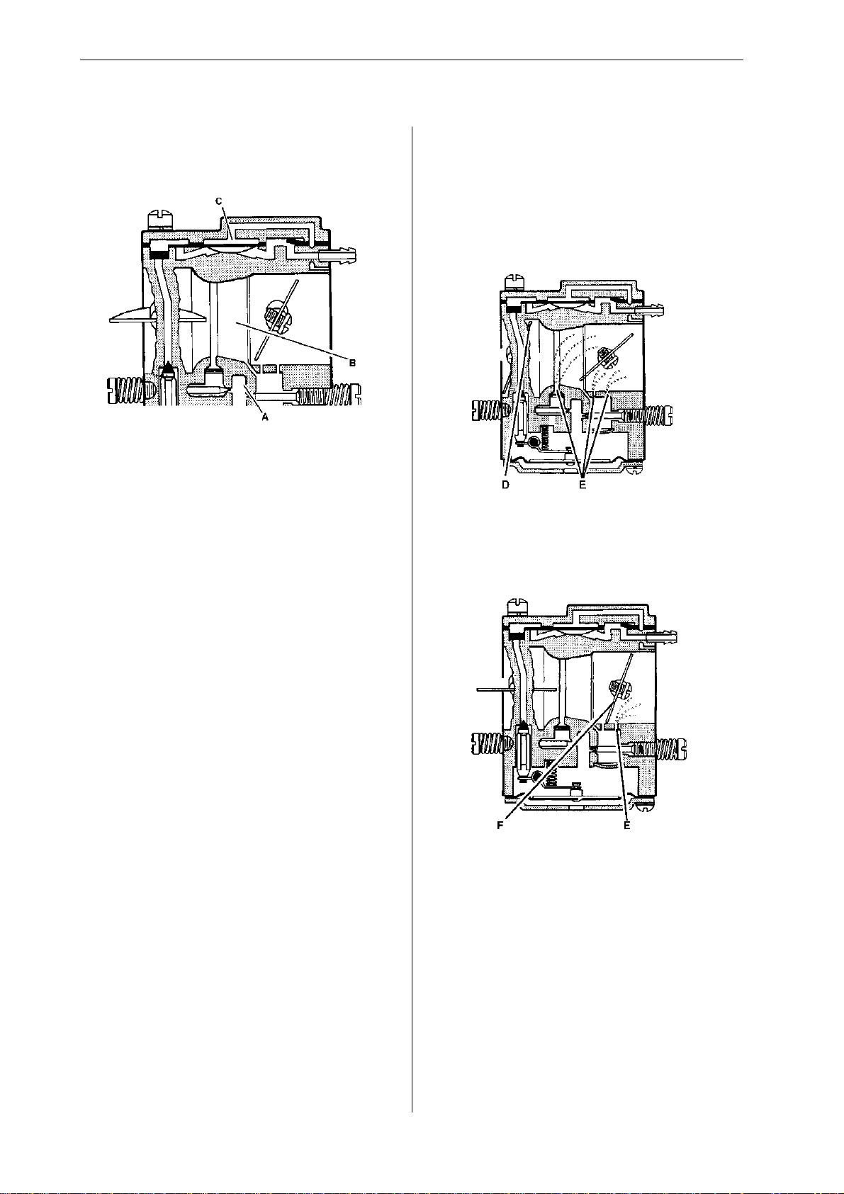
The carburettor consists of three sub-systems:
• The metering unit (A) which contains the jets
and the fuel control mechanism. This measures
out the right amount of fuel to suit the speed of
the saw and the power demand.
• The mixing unit (B) consists of the choke,
diffuser jets and throttle valve. This is where the
air and fuel are mixed to create a flammable
mixture.
The carburettor works in different ways depending
on the setting:
• Cold start mode
• Idling mode
• Part throttle mode
• Full throttle mode
In the cold start mode the choke valve (D) is
completely closed. This increases the vacuum in
the carburettor so that fuel is sucked through the
diffuser jets faster (E).
• The pump unit (C) pumps fuel from the tank to
the metering system inside the carburettor. One
side of the pump diaphragm is connected to the
crankcase and pulses as a result of pressure
changes in the crankcase. The other side of the
diaphragm sucks in the fuel.
In idling mode the throttle valve (F) is closed. Air is
sucked through an aperture in the throttle valve
and a small amount of fuel is supplied through the
diffuser jet (E).
8 – English
www.mymowerparts.com
Page 10
For Husqvarna Parts Call 606-678-9623 or 606-561-4983
Construction and function
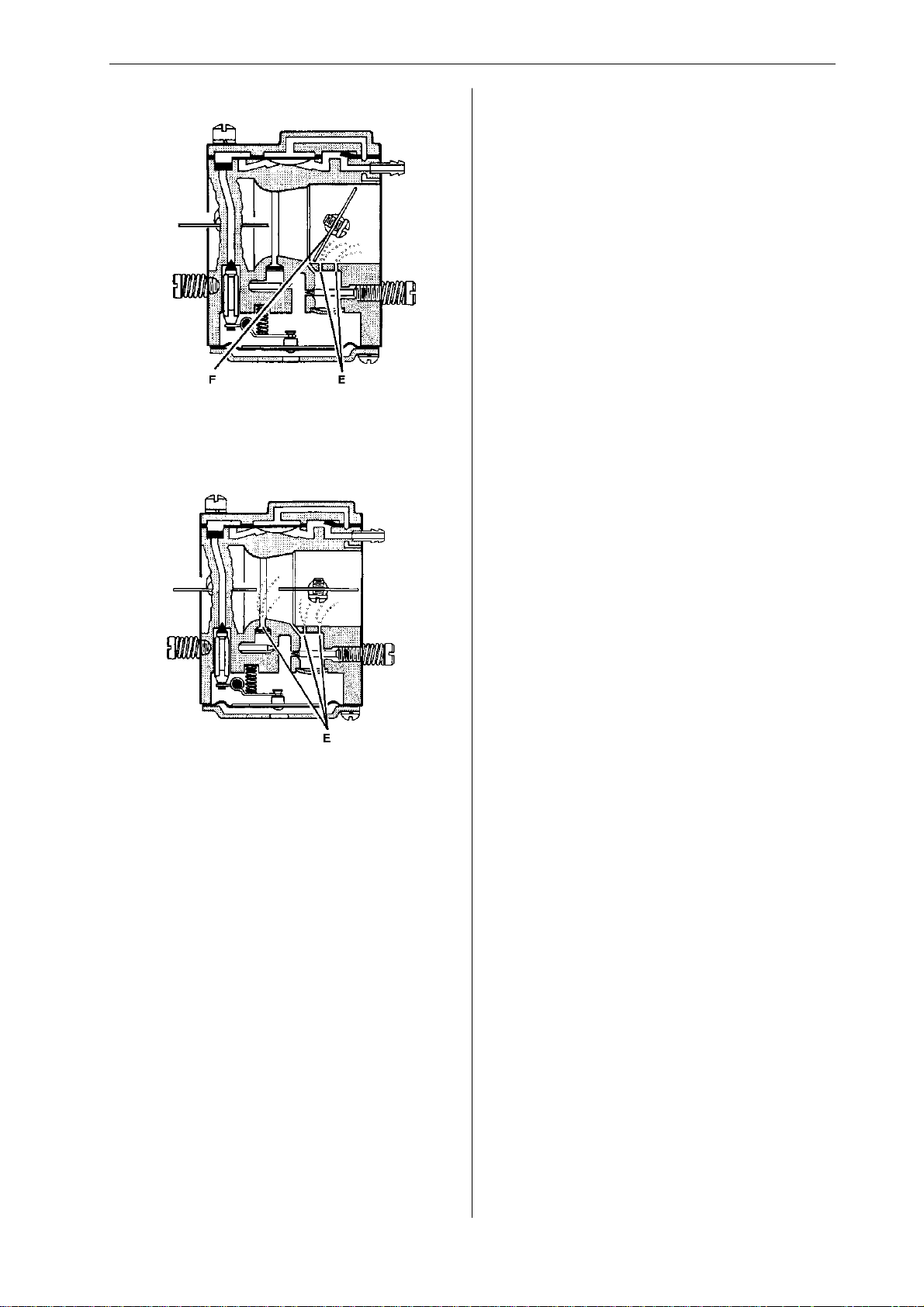
In part throttle mode the throttle valve (F) is partially open. Fuel is supplied through the diffuser jets
(E).
In full throttle mode both valves are open and fuel
is supplied through all the diffuser jets (E).
www.mymowerparts.com
English – 9
Page 11

For Husqvarna Parts Call 606-678-9623 or 606-561-4983
Troubleshooting
The various faults that can affect a chainsaw are divided into four groups. In each group the likely symptoms are given on the left and possible causes are listed on the right. The most likely faults are given first,
and so on.
Starting
Difficulty starting
Carburettor
leaking fuel
Flooding when
engine not
running
Idling (low rpm)
Will not idle
Idling too rich
Adjust L screw
Air filter blocked
Choke not working
Worn choke pivot
Worn choke valve
Fuel filter blocked
Fuel line blocked
Piston ring seized
Blocked impulse channel
Loose or faulty fuel pipe
Hole in diaphragm
Worn needle valve
Needle valve assemb ly stic king
Needle valve set too high
Leak in metering system (air
or fuel)
Loose cover on carburettor
pump side
Worn needle valve
Needle valve set too high
Needle valve assemb ly stic king
Adjust L screw
Leaking air intake hose (rubber)
Loose carburettor mounting bolts
Loose or faulty fuel hose
Fuel filter blocked
Fuel line blocked
Fuel tank vent blocked
Throttle valve pivot stiff
Throttle pushrod sticking
Defective throttle return spring
Bent throttle stop
Faulty diffuser jet
Adjust L screw
Worn needle valve
Needle valve set too high
Worn needle valve lever
Leaking control diaphragm/cover
plate
Needle valve assembly sticking
Idling (low rpm) (cont.)
Idles when L
screw closed
Idling uneven
L screw requires
constant
adjustment
Too much fuel at
idling
Worn needle valve
Leaking control diaphragm/
cover plate
Needle valve assemb ly sticking
Worn needle valve lever
Faulty diffuser jet
Fuel filter blocked
Fuel line blocked
Leaking air intake hose (rubber)
Loose carburettor mounting
bolts
Worn throttle valve pivot
Loose throttle valve screw
Worn throttle valve
Needle valve assembly
sticking
Leak in metering system (air
or fuel)
Metering system centre knob
is worn
Hole in diaphragm
Leaking control diaphragm/
cover plate
Crankcase leaking
Fuel line blocked
Needle valve set too high
Needle valve assemb ly sticking
Leak in metering system (air
or fuel)
Leaking control diaphragm/
cover plate
Faulty diffuser jets
Crankcase leaking
Needle valve set too high
Needle valve assemb ly sticking
Metering system damaged
Worn needle valve
Leaking control diaphragm/
cover plate
Metering system incorrectly
assembled
10 – English
www.mymowerparts.com
Page 12

For Husqvarna Parts Call 606-678-9623 or 606-561-4983
Troubleshooting
High rpm
Will not run
at full throttle
Low power
Will not
“four-stroke”
Adjust H screw
Blocked air filter
Blocked fuel tank vent
Blocked fuel filter
Fuel line blocked
Loose or damaged fuel hose
Impulse channel leaking
Impulse channel blocked
Loose cover on carburettor pump
side
Faulty pump diaphragm
Leaking air intake hose (rubber)
Loose carburettor mounting bolts
Needle valve set too low
Metering system damaged
Metering system incorrectly
assembled
Leaking control diaphragm/cover
plate
Needle valve assembly sticking
Blocked silencer
Adjust H screw
Blocked fuel tank vent
Blocked fuel filter
Impulse channel leaking
Impulse channel blocked
Loose cover on carburettor pump
side
Faulty pump diaphragm
Blocked air filter
Needle valve assembly sticking
Leak in metering system (air or fuel)
Metering system incorrectly
assembled
Loose diaphragm rivet
Hole in diaphragm
Leaking control diaphragm/cover
plate
Blocked fuel tank vent
Blocked fuel filter
Fuel line blocked
Loose or damaged fuel hose
Impulse channel leaking
Impulse channel blocked
Loose cover on carburettor pump
side
Faulty pump diaphragm
Leaking air intake hose (rubber)
Loose carburettor mounting bolts
Needle valve set too low
Leak in metering system (air or fuel)
Metering unit incorrectly
assembled
Loose diaphragm rivet
Hole in diaphragm
Leaking control diaphragm/cover
plate
Acceleration and retardation
Does not
accelerate
Engine stalls
when throttle
released
Over rich
acceleration
Adjust L screw
Adjust H screw
Blocked air filter
Blocked fuel tank vent
Blocked fuel filter
Fuel line blocked
Loose or damaged fuel hose
Impulse channel blocked
Loose cover on carburettor
pump side
Faulty pump diaphragm
Leaking air intake hose (rubber)
Loose carburettor mounting
bolts
Needle valve set too low
Metering system incorrectly
assembled
Needle valve assembly sticking
Faulty diffuser jets
Blocked silencer
Adjust L screw
Adjust H screw
Faulty pump diaphragm
Needle valve set too high
Needle valve assembly sticking
Faulty diffuser jets
Adjust L screw
Adjust H screw
Blocked air filter
Faulty pump diaphragm
Faulty diffuser jets
Troubleshooting methods
In addition to the faults described in the above
table, trouble shooting can be carried out on
specific components or sub-systems of the
chainsaw. The various procedures are
described in the relevant sections, as follows:
• Checking the operation of
the chain brake Page 13
• Measuring the resistance of
the stop plate Page 15
• Pressure testing the carburettor Page 32
• Pressure testing the decompression
valve Page 41
• Pressure testing the cylinder Page 43
www.mymowerparts.com
English – 11
Page 13

For Husqvarna Parts Call 606-678-9623 or 606-561-4983
Repair instructions
Chain brake – dismantling
3
1
Disengage the brake by pushing the kickback
guard backwards. Unscrew the guide bar bolts and
remove the clutch cover, chain and guide bar.
2
WARNING!
Make sure the spring does not fly
out and cause injury. Wear eye
protection.
Remove the screws and carefully remove the cover
from the chain brake spring.
4
Grip the clutch cover carefully in a vice. Release
the brake spring by using the kickback guard from
the saw as a tool. Engage it with the brake mechanism and turn anticlockwise to activate the brake.
Place one hand over the brake spring and insert a
small screwdriver between the rear end of the
spring and the clutch cover. Carefully prise the
spring upwards to release it and slide it onto the
screwdriver shaft. Release the locking washer from
the elbow joint and lift it off.
Cleaning and inspection
• Clean and inspect all parts carefully. If there are
any cracks or other defects replace the damaged
parts with new ones. Always use original parts.
• Measure the thickness of the chain brake band.
It must be no less than 0.6 mm at any point.
• Lubricate the elbow joint with grease.
min 0,6 mm
12 – English
www.mymowerparts.com
Page 14

For Husqvarna Parts Call 606-678-9623 or 606-561-4983
Repair instructions
Chain brake – reassembly
1
Bolt the elbow joint to the brake band and tighten
to a torque of 1–1.5 Nm.
Locate the elbow joint and connected brake band
in their recesses in the clutch cover. Lubricate the
recess for the spring with grease.
2
WARNING!
Make sure the spring does not fly
out and cause injury. Wear eye
protection.
4
Tension the brake spring by using the kickback
guard from the saw as a tool. Engage it with the
brake mechanism and turn clockwise to release
the brake.
5
Turn the chain tensioner anticlockwise as far as it
will go.
Refit:
• guide bar
Grip the clutch cover in a vice. Compress the
spring with special tool 502 50 67-01 and push it
down with your thumb.
3
• chain
• clutch cover
NOTE!
After completing the repair the chain
brake must be tested as described below.
Operating test:
The engine must not be running during the test.
Guide bar length Height
38cm/15" 50 cm/20"
• Hold the chainsaw over a firm surface. The
height of the guide bar above the surface is
given in the table above.
• Let go of the front handle and let the chainsaw
fall towards the surface.
• When the guide bar hits the surface the chain
brake must engage.
Fit the cover over the chain brake spring, tightening
the screws to a torque of 1–1.5 Nm.
www.mymowerparts.com
English – 13
Page 15
For Husqvarna Parts Call 606-678-9623 or 606-561-4983
Repair instructions
Silencer – removal
WARNING!
Do not touch the silencer until it
has cooled down, otherwise you
may burn yourself.
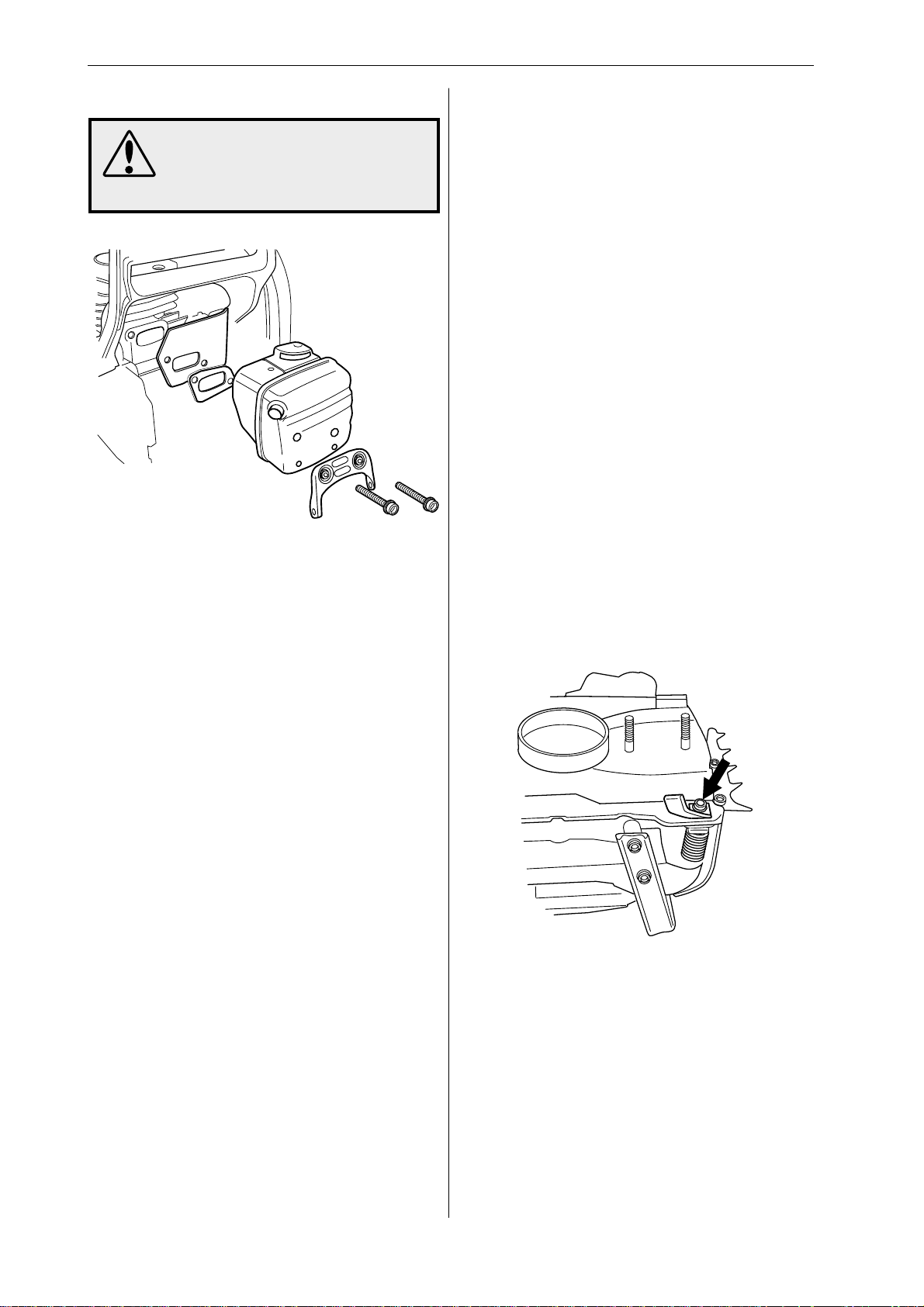
1
Remove the cylinder cover, silencer support,
silencer, gasket and cooling plate.
In order to remove the silencer support you must
first remove the top screw from the bark rest and
partially undo the bottom screw.
2
If the saw is fitted with a spark arrestor mesh this
must also be removed.
Silencer – refitting
1
If the saw is equipped with a spark arrestor mesh
this should be fitted first.
2
Refit
• cooling plate
• gasket
• silencer, tighten bolts to a torque of 12–14 Nm
• silencer support, tighten bolts to a torque of 8–
10 Nm
• bark rest, tighten bolts to a torque of 8–10 Nm
• cylinder cover
3
Run the saw for at least 1 minute, then retighten
the silencer bolts to 8–10 Nm.
Chain catcher – replacement
If the chain catcher is worn it must be replaced with
a new one.
1
Release the brake by pushing the kickback guard
backwards. Undo the guide bar bolts and remove
the clutch cover, chain and guide bar.
2
Cleaning and inspection
Clean and inspect all parts carefully. If there are
any cracks or other defects replace the damaged
parts with new ones.
The spark arrestor mesh is best cleaned with a
wire brush. If the mesh is damaged it must be
replaced.
If the mesh is blocked the saw will overheat and
this will cause damage to cylinder and piston.
Never use the saw with a silencer that is in poor
condition. Always use original parts.
Remove the chain catcher and replace it with a
new one, tightening the bolts to 4–5 Nm. Check
that the vibration damping spring locates correctly
against the crankcase when you bolt the new chain
catcher in position.
3
Turn the chain tensioner anticlockwise as far as it
will go.
Refit:
• guide bar
• chain
14 – English
• clutch cover
www.mymowerparts.com
Page 16
For Husqvarna Parts Call 606-678-9623 or 606-561-4983
Repair instructions
Stop switch – removal
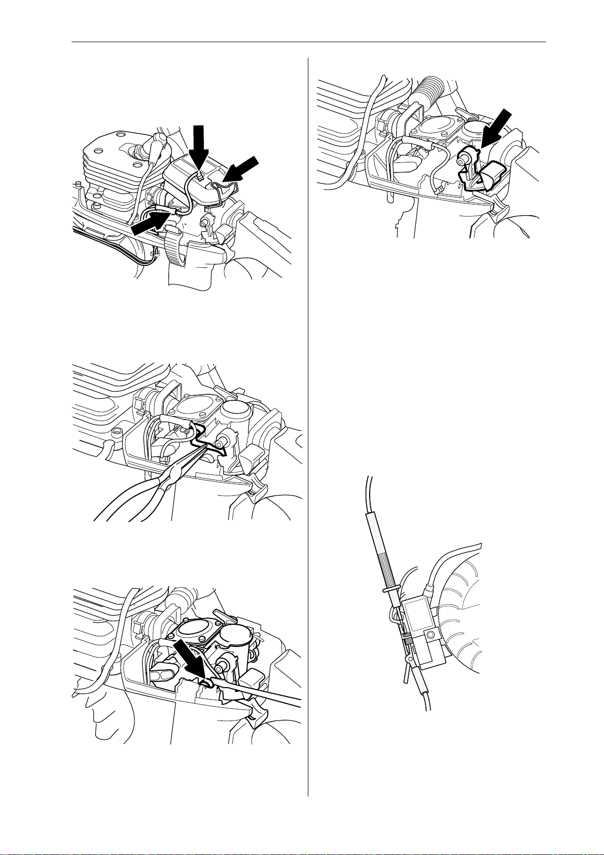
1
Remove the cylinder cover.
2
Release the clip and remove the air filter. Disconnect both leads from the stop plate and stop
switch.
3
5
Carefully prise the stop switch’s upper mounting off
the air filter holder while lifting the switch to release
it from the lower mounting.
Cleaning and inspection
Remove the stop plate by carefully sliding it over
the lug on the front mounting.
4
Clean and inspect all parts carefully. If there are
any cracks or other defects replace the damaged
parts with new ones. Always use original parts.
Stop switch – resistance measurement
Remove the cylinder cover and starter assembly.
Clean the mating surfaces and check the resistance as follows:
Carefully prise the carburettor assembly off the lefthand rubber mounting using a small screwdriver.
www.mymowerparts.com
Measure the resistance by connecting a multimeter
to the ignition coil. NOTE! The switch must be in
the “on” position to give the correct reading.
The resistance must not be higher than 0.2 ohm
when the switch is in the on position.
English – 15
Page 17
For Husqvarna Parts Call 606-678-9623 or 606-561-4983
Repair instructions
Stop switch – refitting
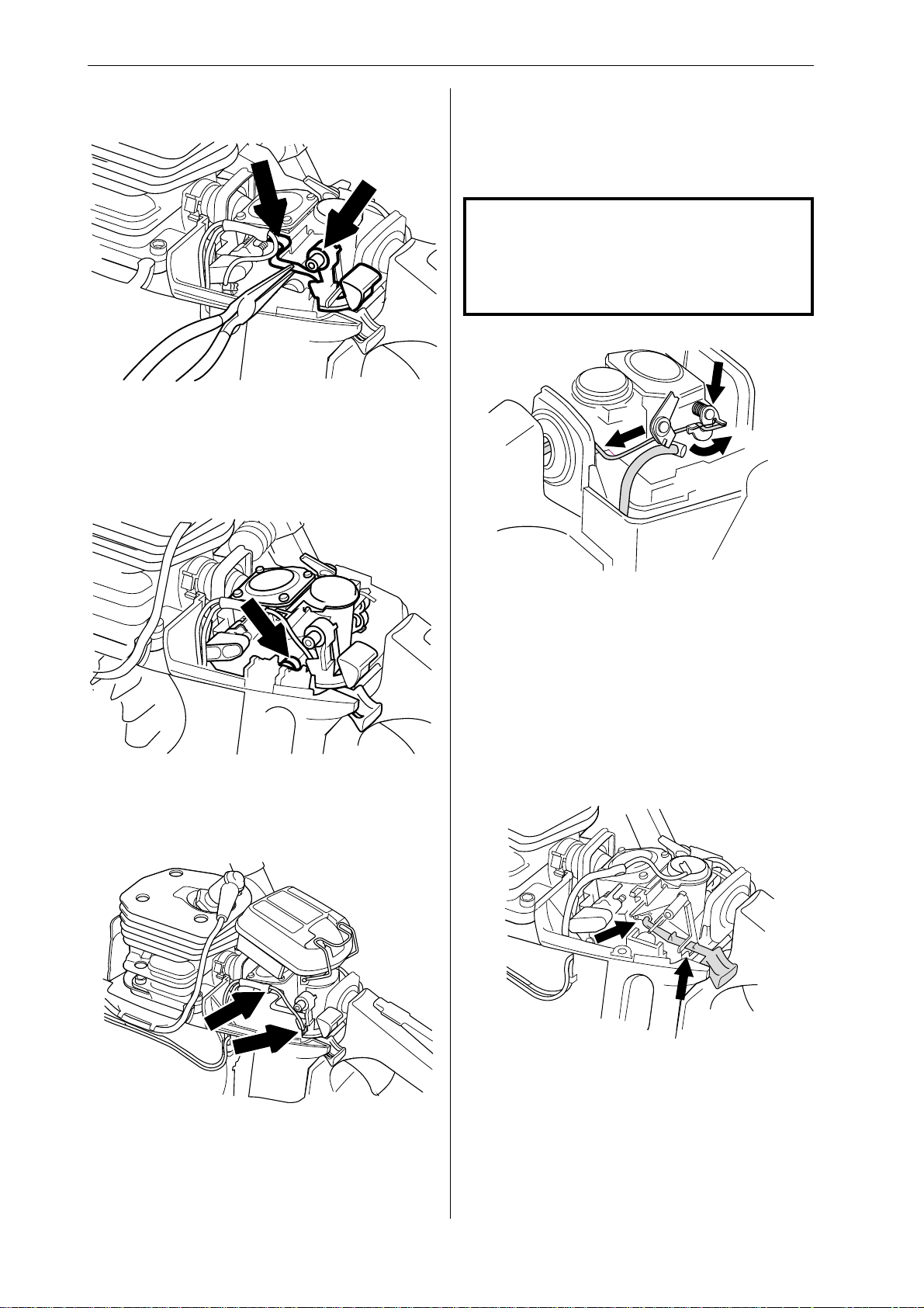
1
Carefully press the new stop switch into place .
Check that the switch’s upper mounting clips over
the air filter holder.
2
Choke control – removal
1
Remove the cylinder cover, air filter and stop
switch. Disconnect the fuel hose from the carburettor.
NOTE!
Do not use knurled pliers to disconnect or
reconnect the fuel hose. This could damage the hose and lead to leakage or fracture.
2
A
C
B
Push the carburettor gently back into the left-hand
rubber mounting.
3
Disconnect the pushrod from the carburettor by first
carefully prising up the spring over the end of the
rod, where it connects to the throttle lever (A). Then
press the throttle lever forwards (B) while pressing
the throttle pushrod backwards (C) and lifting it off
the lever. Withdraw the throttle pushrod from the
tank and lift it upwards without pulling it through the
rubber inlet manifold. Carefully release the carburettor assembly from the right-hand rubber mounting and lift it upwards.
3
Reconnect the lead to the stop plate and stop
switch.
Refit the air filter and secure it with the clip.
4
Refit the cylinder cover.
16 – English
www.mymowerparts.com
Compress the clip that holds the choke control to
the carburettor while pulling it out at the same time.
Disconnect the choke control from the air filter
holder.
Page 18
For Husqvarna Parts Call 606-678-9623 or 606-561-4983
Repair instructions
Choke control – refitting
First reattach the choke control to the air filter , then
press it onto the carburettor so that the clips engage.
Then refit:
• stop switch
• carburettor into its rubber mountings
• throttle pushrod into the fuel tank and connect to
throttle lever.
• lift the spring arm over the throttle pushrod
• fuel hose to the carburettor
• air filter and cylinder cover
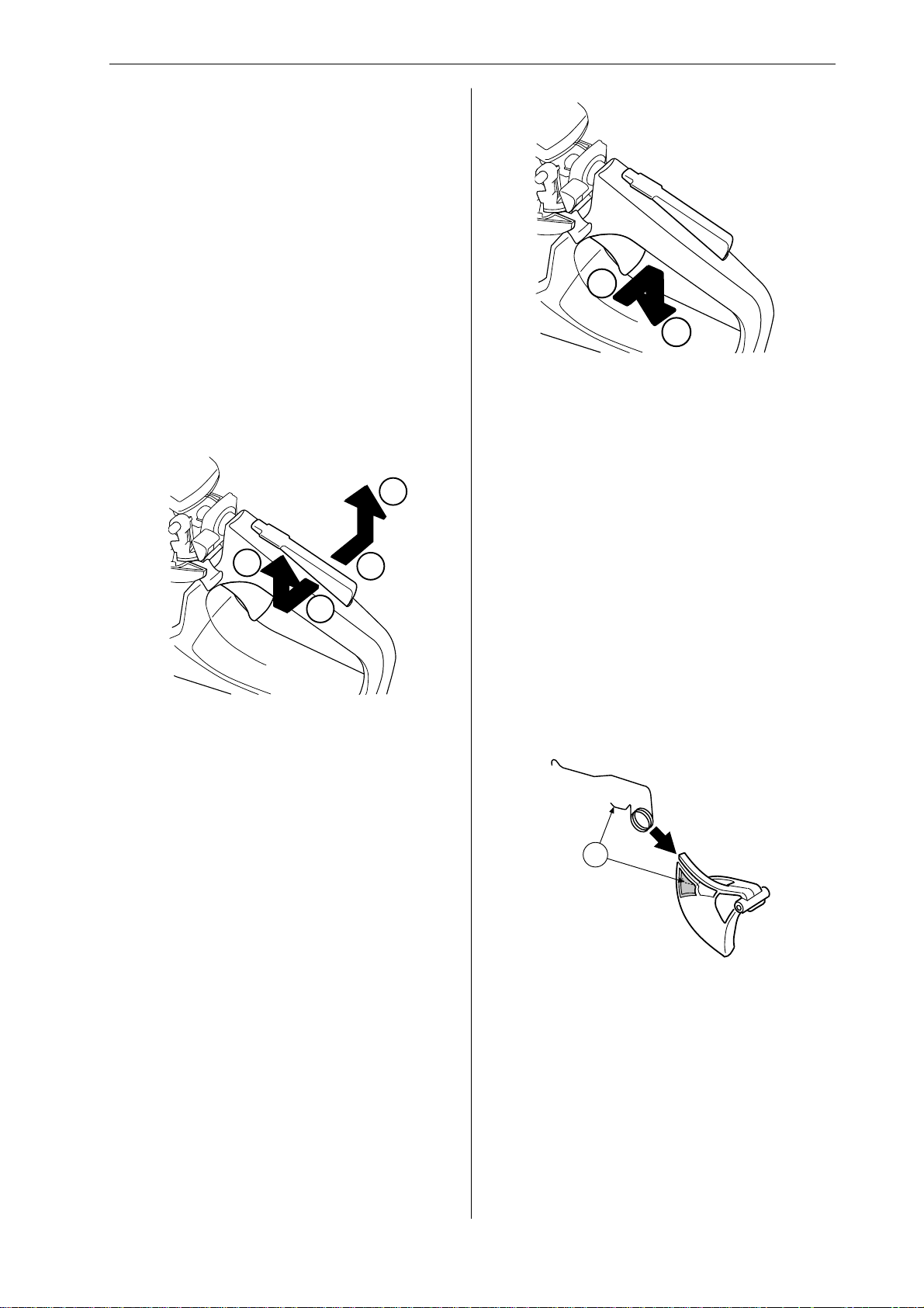
Throttle lock, throttle trigger and return
spring – removal
1
2
4
1
3
3
1
2
Remove the throttle trigger by first pressing it
towards the clutch side of the saw until it clicks,
then towards the flywheel side until it clicks again.
Remove it from the tank and lift out the return
spring.
Cleaning and inspection
• Clean and inspect all parts carefully. If there are
any cracks or other defects replace the damaged
parts with new ones. Alw ays use original parts.
• Lubricate the throttle lock with oil.
• Check that the spring is not broken and has not
lost its tension.
Remove the throttle lock by pressing it to the right
and pulling upwards at the same time until you
hear a click. Then repeat by pressing it to the left
(3) and pulling upwards (4). When both of the lugs
on the lock have cleared the tank pull the lock
backwards.
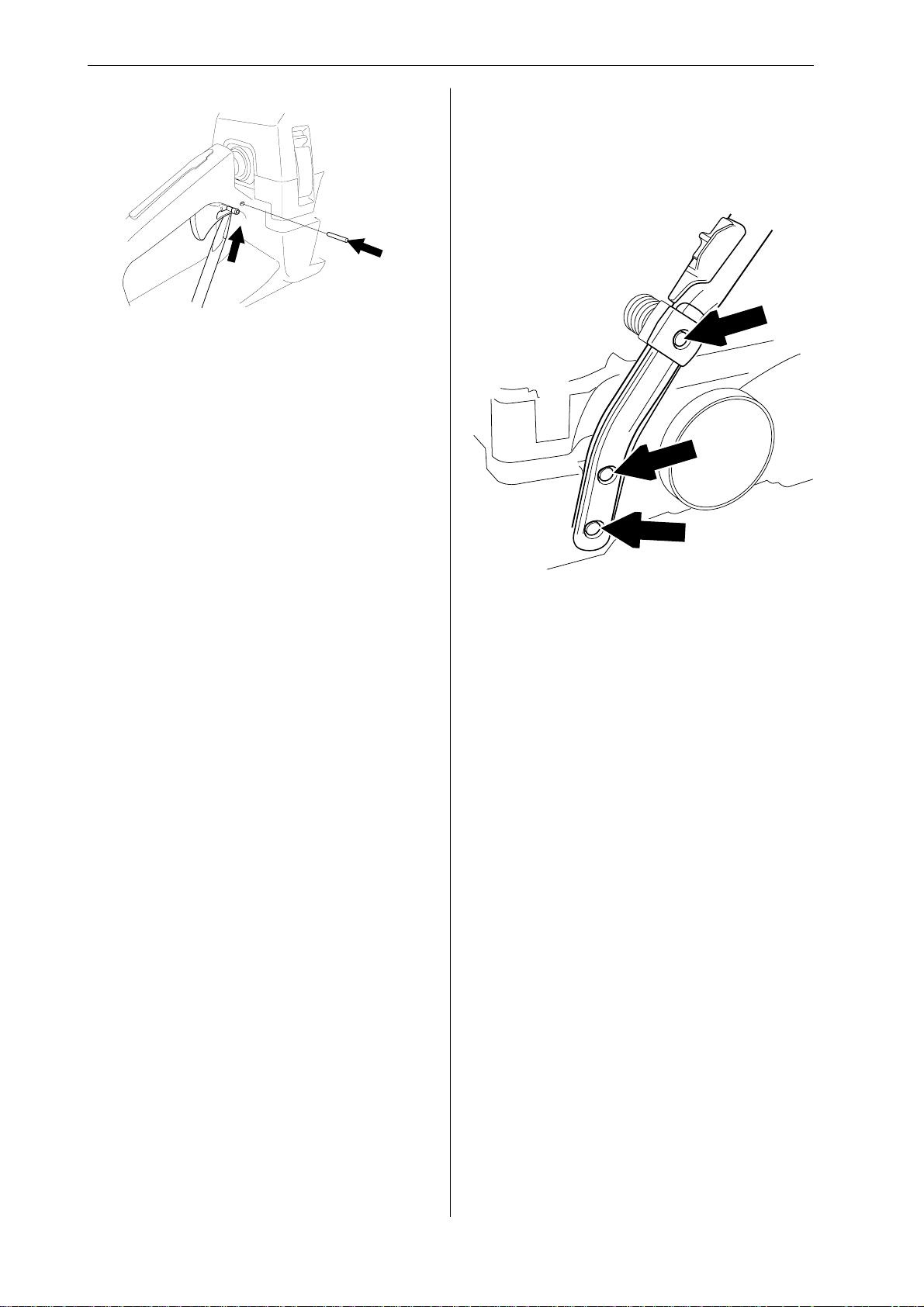
2
Drive out the steel pin using a 2.5 mm/0.1" diameter drift. Push it out from the flywheel side of the
saw.
Throttle lock, throttle trigger and return
spring – refitting
1
A
Refit the return spring to the throttle trigger as
shown. Make sure the spring is correctly positioned
by engaging one end in the slot in the throttle
trigger (A).
Press the coil of the return spring into the handle
and press the short end of the spring (A) into the
recess in the throttle trigger.
www.mymowerparts.com
English – 17
Page 19
For Husqvarna Parts Call 606-678-9623 or 606-561-4983
Repair instructions
2
First insert the rear edge of the throttle trigger into
the tank. Then push/clip the front edge into the two
clips on the tank with the aid of a combination tool,
for example. Drive in the steel pin from the clutch
side. Use a 2.5 mm/0.1" diameter drift.
3
Then press down the return spring while pressing
the throttle lock forwards/upwards into the retaining
clip in the fuel tank until you hear a click. Release
the return spring in the throttle lock, then press the
lock down onto the tank.
Hand grip heater on model 357XP/G
and 359/G – removal
No heating or heating only in front hand grip
• Front hand grip – troubleshooting
1
4
Check the operation of the throttle lock by trying to
press the throttle trigger without pressing down the
throttle lock. Also check that the throttle lock and
throttle trigger return freely to their original positions when released.
Remove the three bolts that secure the co v er over the
front hand grip. Disconnect the leads from the switch
and generator and measure the resistance of the
hand grip heater, which should be 3–4 ohm. Replace
the front hand grip if the resistance is higher.
2
Reconnect the leads and secure the cover back in
place over the front hand grip.
18 – English
www.mymowerparts.com
Page 20

For Husqvarna Parts Call 606-678-9623 or 606-561-4983
Repair instructions
• Generator – troubleshooting
1
Remove the cylinder cover and cover from the
front hand grip. Disconnect the black lead from the
generator and connect a multimeter between it and
a clean area on the cylinder. The multimeter should
show a resistance of 0.9–1.3 ohm. If higher or
lower, replace the generator, see ”Replacing the
generator”.
2
Reconnect the lead and refit the hand grip cover
and cylinder cover.
• Switch – troubleshooting
1
Carefully free the switch and frame from the front
hand grip using a screwdriver.
2
Disconnect the leads from the switch and connect
a multimeter to it. The meter should read over
1000 ohm when the switch is in the “0” position.
The meter should read no higher than 0.1 ohm with
the switch in the “1” position. Replace the meter if
the readings are outside these limits.
Rear hand grip heater not working
Heater element and rear hand grip –
removal
1
Remove the cylinder cover, hand grip cover, hand
grip and right-hand stop.
Then remove:
• throttle lock, throttle trigger and return spring,
see ”Throttle lock, throttle trigger and return
spring - removal”
• fuel hose and throttle pushrod from the carburettor
Unbolt the rear tank mounting from the crankcase,
i.e. the rear vibration damping spring, and both
stops. Lower the tank as far as it will go to allow
access to the heater lead where it is secured to the
tank.
Refit:
• fuel tank with both stops (3-4Nm) and the rear
vibration damping spring (4-5Nm)
• throttle lock, throttle trigger and return spring,
see ”Throttle lock, throttle trigger and return
spring - removal”.
• fuel hose and throttle pushrod to the carburettor
(check that the hose is not trapped between the
tank and crankcase, measurement 43 mm (1.69
inches))
• Rear hand grip heater – troubleshooting
1
Remove the cylinder cover, air filter and cover from
the rear hand grip.
2
Remove the throttle pushrod, see “Carburettor –
removal”.
3
Remove the bolt from the plate at the base of the
carburettor to release the lead for the heater
element.
4
Disconnect the red lead from the heater element
and connect a multimeter between it and the black
earth lead that is bolted to the bottom of the
carburettor on the clutch side of the saw. The meter
should read 0.7–1.2 ohm. If the reading is higher
replace the heater element.
• hand grip cover, air filter and cylinder cover
Heater element and rear hand grip –
removal
1
Screw the heater element into place using the two
screws and feed the leads through the rear hand
grip. Secure the red lead in the clip on the tank and
connect it. Feed the black lead through crankcase
and secure/earth it to the base of the carburettor
using the bolt at the front on the clutch side of the
saw. Tighten to a torque of 3–4 Nm.
2
Refit:
• fuel tank with both stops (3-4Nm) and the rear
vibration damping spring (4-5Nm)
• throttle lock, throttle trigger and return spring,
see ”Throttle lock, throttle trigger and return
spring - removal”.
• fuel hose and throttle pushrod to the carburettor
(check that the hose is not trapped between the
tank and crankcase, measurement 43 mm (1.69
inches))
• hand grip cover, air filter and cylinder cover
www.mymowerparts.com
English – 19
Page 21
For Husqvarna Parts Call 606-678-9623 or 606-561-4983
Repair instructions
Hand grip heater on model 357XP/G
and 359/G – refitting
1
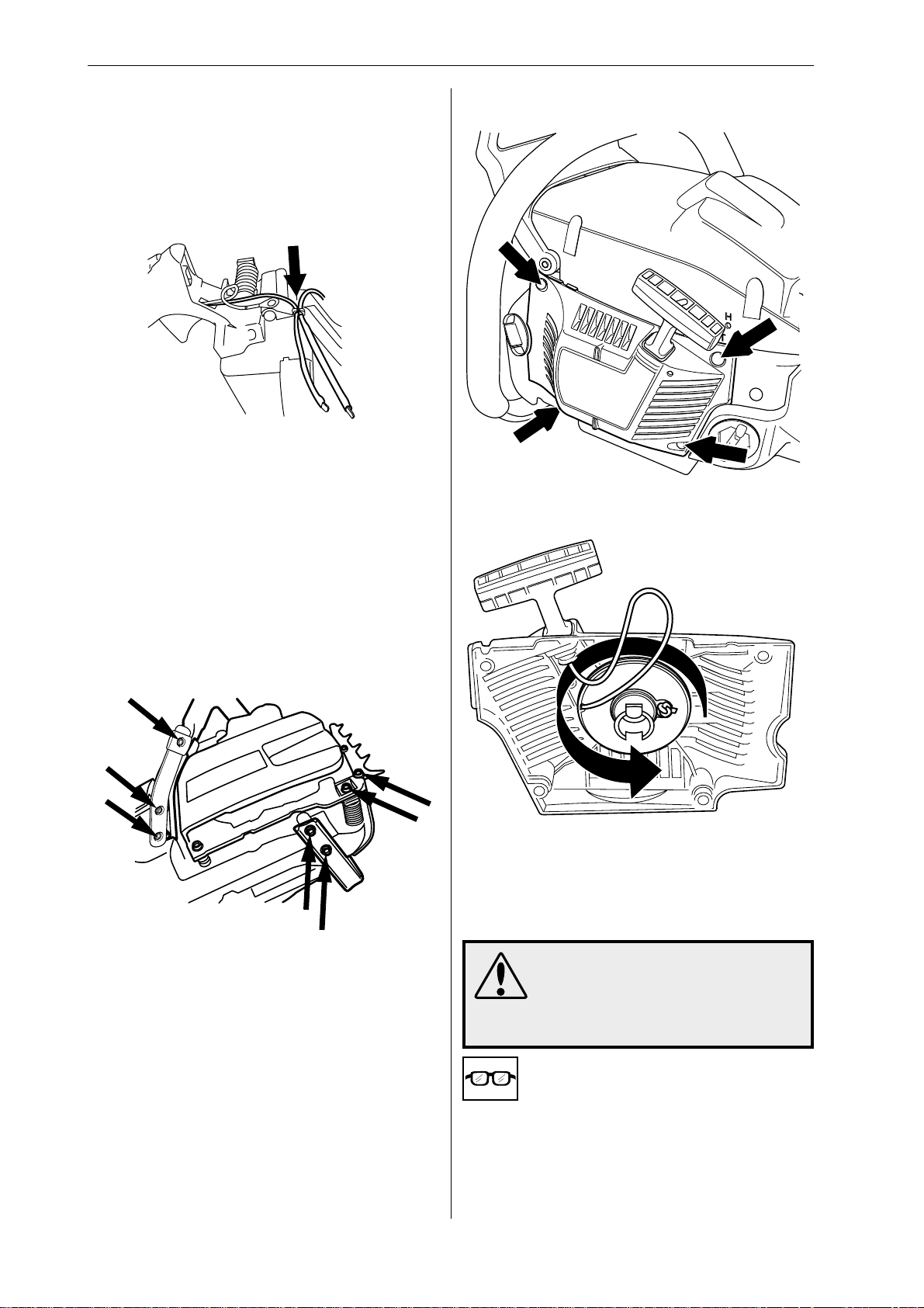
Feed the leads into the rear hand grip and insert
the heater element in the hand grip. Screw in the
two bolts through the right side of the hand grip to
secure the heater.
2
Press the black lead into the base of the carburettor and connect it with the bolt.
Tighten to a torque of 3–4 Nm.
3
Run the red lead to the front hand grip and connect
it.
Starter assembly – removal
1
Undo the four bolts that fasten the starter assembly
to the crankcase and lift off the starter assembly.
2
4
Refit the throttle trigger and throttle lock and check
that they work correctly, see ”Throttle lock, throttle
trigger and return spring - removal”.
5
Bolt the vibration damping springs that hold the
tank unit back in place and refit the cover over the
front hand grip.
Tighten to a torque of 4–5 Nm.
Pull out about 30 cm of the cord and fasten it in the
notch in the pulley rim. Release the tension in the
return spring by letting the pulley wind backwards
slowly.
3
WARNING!
If the recoil spring is still under
tension when the pulley is removed it can fly out and cause injury. Wear eye protection.
20 – English
Remove the bolt from the centre of the pulley and
lift off the pulley.
www.mymowerparts.com
Page 22
For Husqvarna Parts Call 606-678-9623 or 606-561-4983
Repair instructions
Cleaning and inspection
Clean the parts and check the following:
• The starter cord.
• The teeth on the pulley, lubricate with oil.
• That the pawls on the flywheel are undamaged,
i.e. that they spring back towards the centre and
move freely.
• Lubricate the return spring with light oil.
Replacing a broken or worn starter cord
1
Cleaning and inspection:
• Clean and inspect all parts carefully. If there are
any cracks or other defects replace the damaged parts with new ones. Lubricate the return
spring with light oil.
Tensioning the recoil spring
1
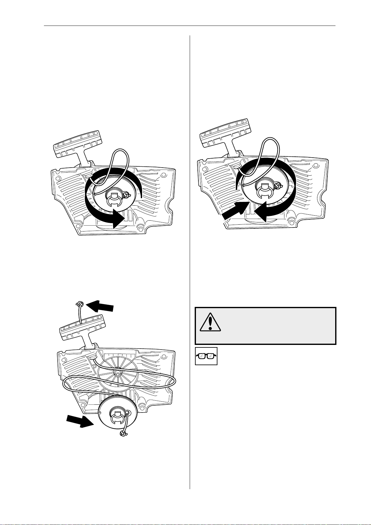
Before replacing a worn starter cord the tension in the
recoil spring must be released. Pull the starter cord out
through the notch in the pulley rim and wind the pulley
anti-clockwise to release the tension in the spring.
2
Remove the bolt from the centre of the pulley and
lift off the pulley.
3
Fasten the starter cord in the notch in the pulley
rim and wind the pulley about 2 turns clockwise.
Check that the pulley is free to rotate at least
another half turn when the starter cord is fully
extended.
Replacing a worn recoil spring
WARNING!
Make sure the recoil spring does
not fly out and cause injury. Wear
eye protection.
1
Remove the bolt from the centre of the pulley and
lift off the pulley and spring.
2
Remove the broken recoil spring.
Fit a new cord through the hole in the pulley and tie
a knot to secure it. Feed the other end of the cord
through the hole in the starter housing and through
the starter handle, then tie a double knot in the
end. Wind about 3 turns of the starter cord onto the
pulley. Fit the bolt through the centre of the pulley
and tighten to a torque of 2–3 Nm.
www.mymowerparts.com
English – 21
Page 23
For Husqvarna Parts Call 606-678-9623 or 606-561-4983
Repair instructions
3
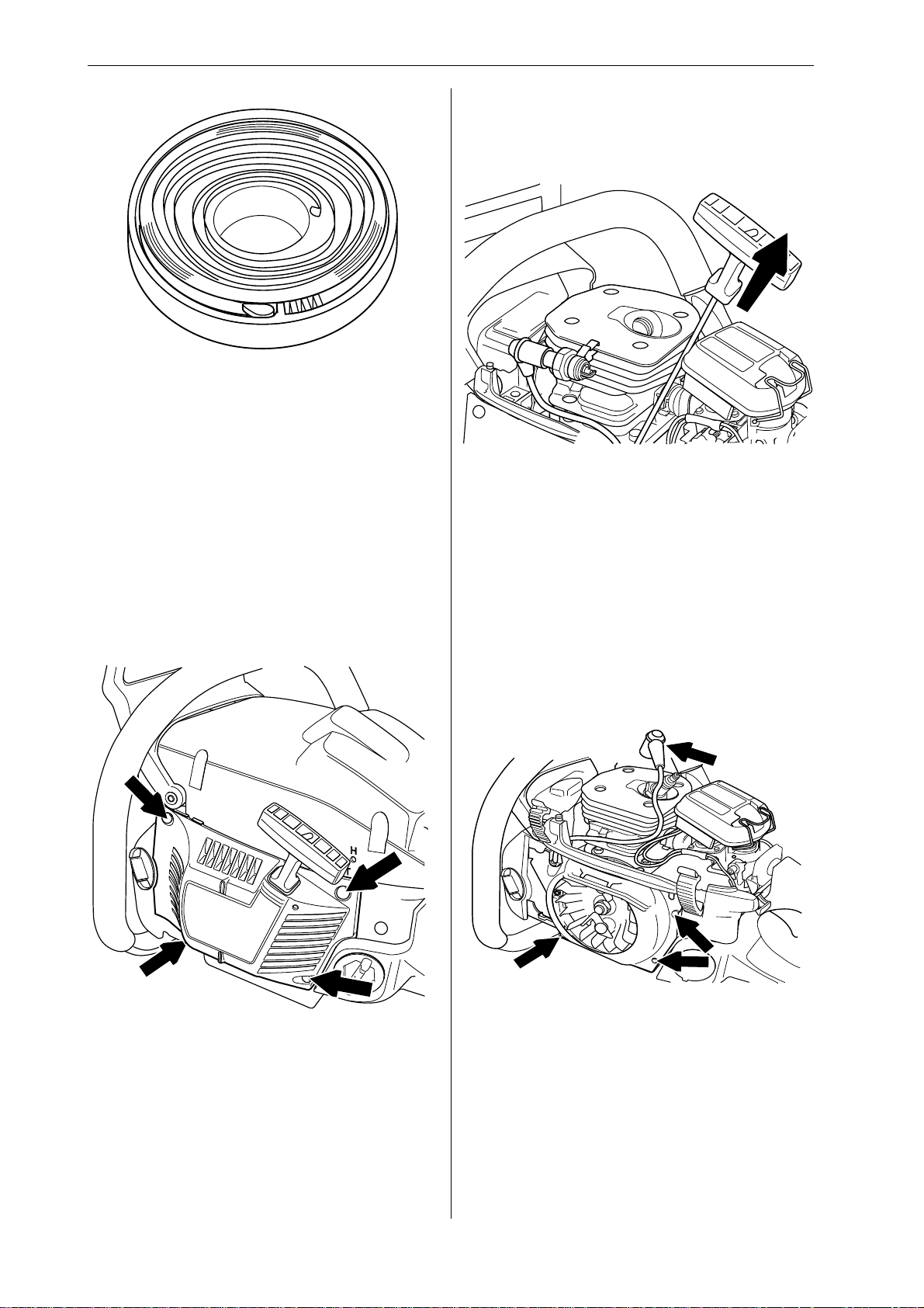
Fit a new recoil spring. Lubricate the recoil spring
with light oil.
4
Fit the bolt through the centre of the pulley and
tighten to a torque of 2–3 Nm.
Tension the recoil spring, see ”Tensioning the recoil
spring”.
Ignition module – testing
If there is a fault in the ignition system the ignition
module must be tested before the ignition system
is removed.
Test the ignition module as follows:
• Connect a test spark plug 502 71 13-01 to the
ignition lead and clip the test spark plug onto the
cylinder.
Starter assembly – refitting
1
Position the starter assembly on the crankcase and
tighten the bolts to a torque of 2.5–3.5 Nm.
• Turn the engine over using the starter cord.
• If the test spark plug produces a spark the
ignition module is OK.
Ignition module/flywheel – removal
1
Remove the cylinder cover. Disconnect the HT
lead, remove the spark plug and fit piston stop
502 54 15-01 in its place. Take off the starter
assembly, release the leads from the cable guide
and remove it.
22 – English
www.mymowerparts.com
Page 24
For Husqvarna Parts Call 606-678-9623 or 606-561-4983
Repair instructions
2
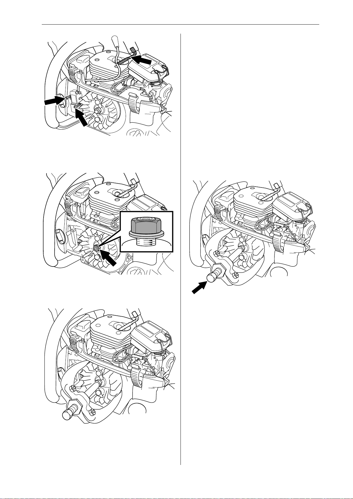
If replacing the ignition module, disconnect its leads
and unscrew it. The ignition module can be left in
place if you are simply removing the flywheel.
3
Cleaning and inspection
• Clean all parts, especially the tapers on the
flywheel and shaft.
• Check that the flywheel is not cracked or damaged in any other way.
Replacing the generator, model 357XP/G
and 359/G
1
Remove the cylinder cover. Disconnect the HT lead,
remove the spark plug and fit piston stop 502 54 1501 in its place. Take off the starter assembly, release
the leads from the cable guide and remove it.
Remove the cov er from the hand g rip.
2
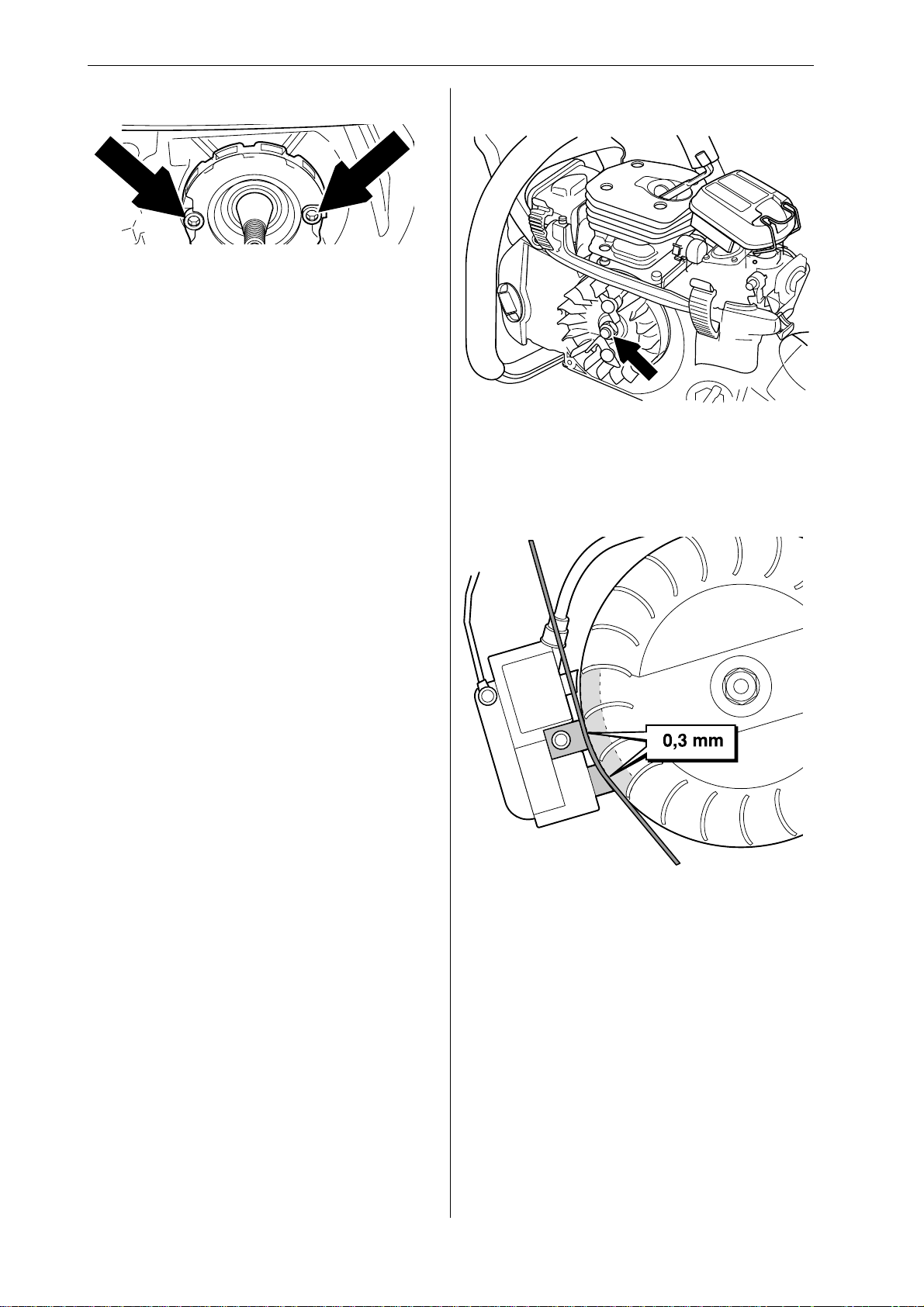
Loosen the flywheel nut using a suitable socket and
unscrew it until it is flush with the end of the shaft.
4
Position puller 504 90 90-02 over the magnets and
counterweight on the flywheel. Tighten 2–3 turns
and tap the head of the puller with a metal mallet to
release the flywheel. Remove the puller, nut and
washer. Lift off the flywheel.
Loosen the flywheel nut using a suitable socket
and unscrew it until it is flush with the end of the
shaft.
Position puller 504 90 90-02 over the magnets and
counterweight on the flywheel. Tighten 2–3 turns
and tap the head of the puller with a metal mallet to
release the flywheel. Remove the puller, nut and
washer. Lift off the flywheel.
www.mymowerparts.com
English – 23
Page 25
For Husqvarna Parts Call 606-678-9623 or 606-561-4983
Repair instructions
3
Unscrew the two bolts from the generator but leave
the generator in place.
4
Remove the fuel hose and throttle pushrod from
the carburettor.
Unbolt the rear tank mounting from the crankcase,
i.e. the rear vibration damping spring, and both
stops. Lower the tank as far as it will go to allow
access to the heater lead where it is connected to
the tank.
5
Disconnect the generator lead from the hand grip
and unclip it from the tank. Remove the generator
and lead.
Ignition module and flywheel – refitting
1
Place the flywheel on the crankshaft. Turn the
flywheel so that the key lines up with the k eyway in
the shaft.
Fit the washer and nut on the shaft and tighten to a
torque of 25-30 Nm.
2
Generator – refitting
1
Feed the generator lead through the holes in the
crankcase and hand grip. Bolt the generator in
position, tightening the bolts to a torque of 5 Nm.
Clip the lead to the tank.
NOTE! The lead connector must be positioned to
the right of the clip. Connect the lead to the connector on the hand grip and refit the cover.
2
Refit:
• fuel tank with both stops and rear vibration
damping spring
• fuel hose to carburettor, hose length between
tank and crankcase: 43 mm (1.69 inches) and
between crankcase and carburettor: 53 mm
(2.09 inches)
• throttle pushrod to carburettor
• flywheel with nut and washer
• cable guide, leads and starter assembly
Remove the piston stop and reconnect the HT lead
and cylinder cover.
To refit the ignition module proceed as follows:
Turn the flywheel so that the magnets are in line
with the ignition module. Fit the ignition module with
the plastic feeler gauge (502 51 34-01) held in
position at the same time, without tightening the
bolts. Connect the black earth lead to the front
screw on the ignition module. Adjust the gap
between the ignition module and magnet to 0.3 +/-
0.1 mm. The gap must be measured at either of the
two lowest pegs on the ignition module. Tighten the
bolts to 8-10 Nm. Connect the blue lead to the
ignition module.
24 – English
www.mymowerparts.com
Page 26
For Husqvarna Parts Call 606-678-9623 or 606-561-4983
Repair instructions
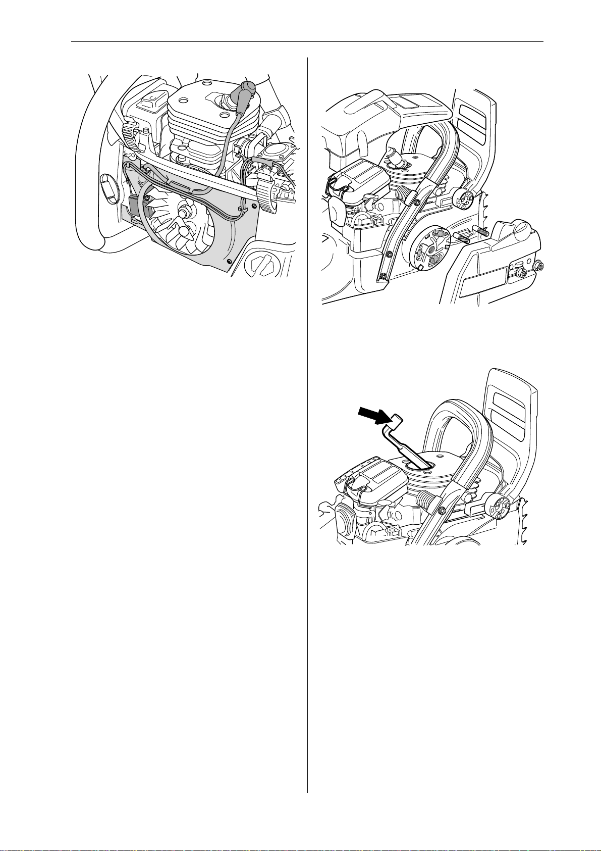
3
Then refit:
• cable guide and press the leads into position
• HT lead
• starter assembly, tighten to a torque of 2.5–3.5
Nm
• cylinder cover
Centrifugal clutch – removal
1
Remove the cylinder cover. Disengage the chain
brake by pushing the kickback guard backwards.
Undo the guide bar bolts and remove the clutch
cover, chain and guide bar.
2
Disconnect the HT lead. Remove the spark plug
and fit piston stop 502 54 15-01 in its place.
www.mymowerparts.com
English – 25
Page 27
For Husqvarna Parts Call 606-678-9623 or 606-561-4983
Repair instructions
3
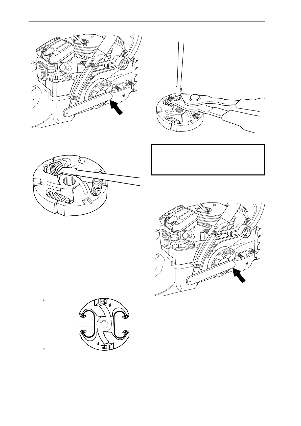
Unbolt the clutch by turning the nut clockwise using
tool 502 52 22-02.
4
Centrifugal clutch – refitting
1
NOTE!
Handle the clutch springs carefully. If they
are opened up too much they could
damage the saw.
Carefully prise out the clutch springs with a screwdriver.
Inspection and cleaning
• Clean and inspect all parts carefully. If there are
any cracks or other defects replace the damaged parts with new ones. Always use original
parts.
Insert the clutch springs in the shoes using circlip
pliers and a screwdriver.
2
Fit the clutch and tighten anticlockwise as far as it
will go. Then tighten to a torque of at least 20 Nm
using tool 502 52 22-02.
3
Remove the piston stop . Fit the spark plug, tightening
it to a torque of 15 Nm, then connect the HT lead.
• Check the thickness of the clutch shoes by using
vernier callipers to measure the diameter of the
clutch. If the diameter is less than 65 mm the
clutch assembly must be replaced.
26 – English
www.mymowerparts.com
Then refit:
• cylinder cover
• guide bar
• chain
• clutch cover
Page 28
For Husqvarna Parts Call 606-678-9623 or 606-561-4983
Repair instructions
Oil pump – removal
1
Empty and clean the oil tank.
2
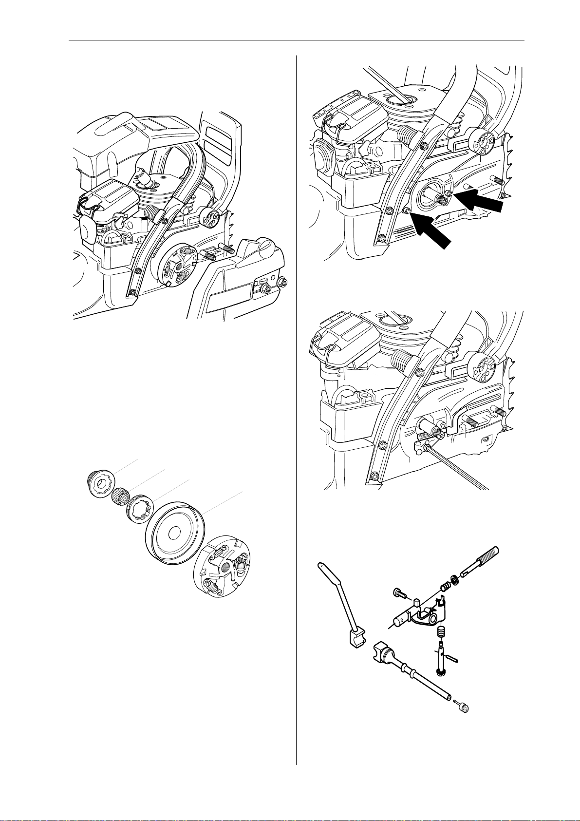
Remove the cylinder cover. Disengage the chain
brake by pushing the kickback guard backwards.
Undo the guide bar bolts and remove the clutch
cover, chain and guide bar. Disconnect the HT
lead. Remove the spark plug and fit piston stop
502 54 15-01 in its place. Unbolt the clutch using
tool 502 52 22-02 and a suitable socket or combination spanner. Turn the nut clockwise to remove it.
4
Remove the chain guide plate.
5
3
D
C
B
A
Unbolt and remove the clutch drum (A), chain
sprocket (B), needle bearing (C) and pump drive
wheel (D).
Unbolt the oil pump from the crankcase.
6
C
A
B
Remove the oil hose and filter (A).
www.mymowerparts.com
English – 27
Page 29
For Husqvarna Parts Call 606-678-9623 or 606-561-4983
Repair instructions
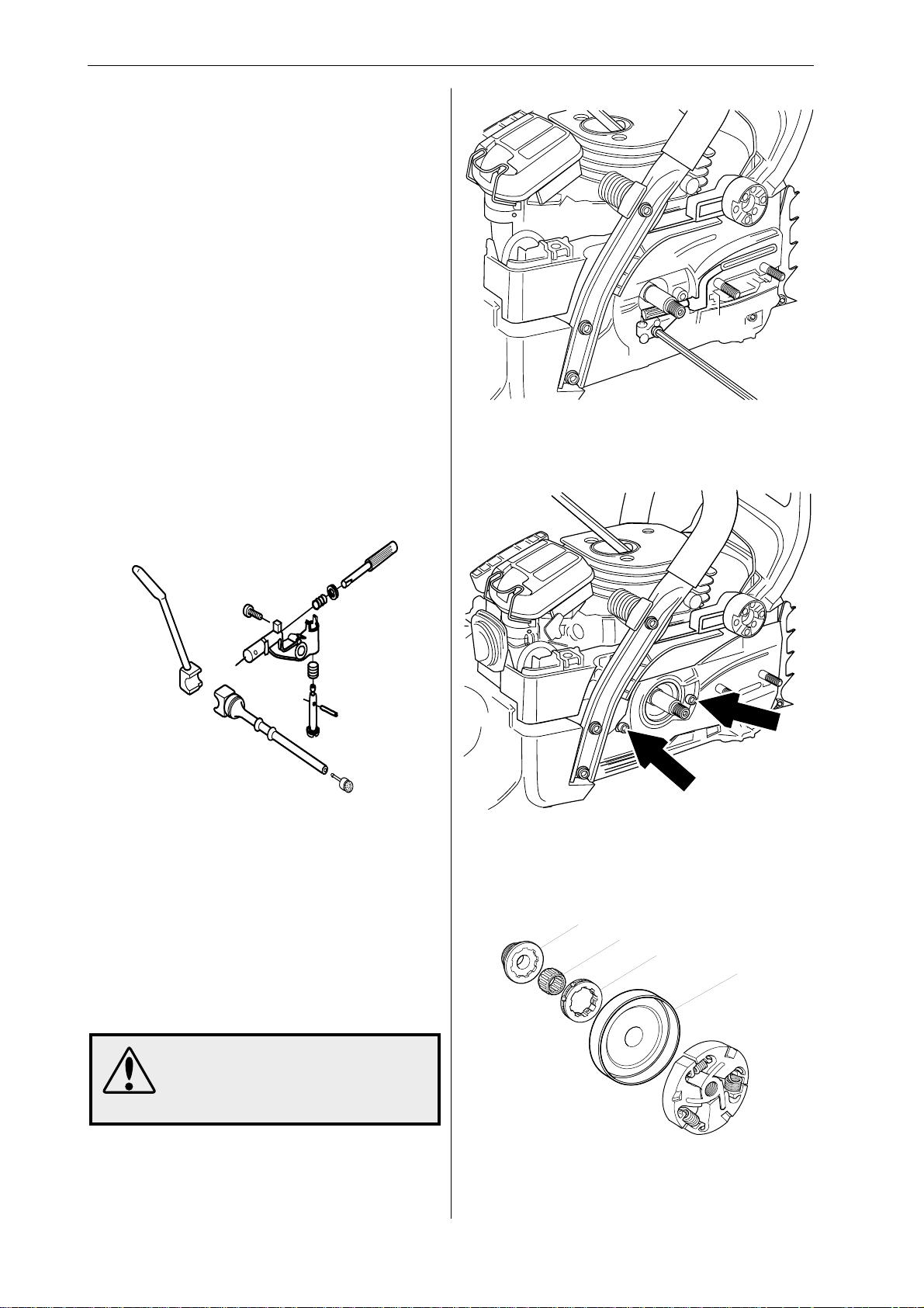
7
Remove the pin (B) from the adjuster screw, using
a small drift to press it out.
8
Press in the pump piston (C) so that the adjuster
screw (D) can be removed. Remove the pump
piston.
Cleaning and inspection
• Clean and inspect all parts carefully. If there are
any cracks or other defects replace the damaged parts with new ones. Always use original
parts.
• Lubricate all moving parts with grease
Oil pump –refitting
1
C
4
Refit the oil pump, tightening the bolts to a torque
of 3–4 Nm.
5
A
B
Lubricate the pump piston (C) with grease and fit
the pump piston and washers.
2
Press down the pump piston (C). Fit the adjuster
screw and spring so that the pin (B) can be
pressed into position.
3
Reconnect the oil hose and filter (A).
WARNING!
Poor chain lubrication can result
in failure of the chain, which could
cause serious or fatal injury.
Fit the chain guard plate, tightening the bolts to a
torque of 2–3 Nm.
6
D
C
B
A
28 – English
Lubricate the needle bearing with grease. Fit the
pump drive wheel (D), needle bearing (C), chain
sprocket (B), if fitted, and clutch drum (A).
www.mymowerparts.com
Page 30
For Husqvarna Parts Call 606-678-9623 or 606-561-4983
Repair instructions
7
Fit the clutch and tighten anticlockwise as far as it
will go. Then tighten to a torque of at least 20 Nm
using tool 502 52 22-02.
8
Remove the piston stop. Fit the spark plug, tightening it to a torque of 15 Nm, then connect the HT
lead. Then refit the cylinder cover, guide bar, chain
and clutch cover.
9
Refill the tank with oil. For more information see
the user instructions for this model for the recommended grade of oil.
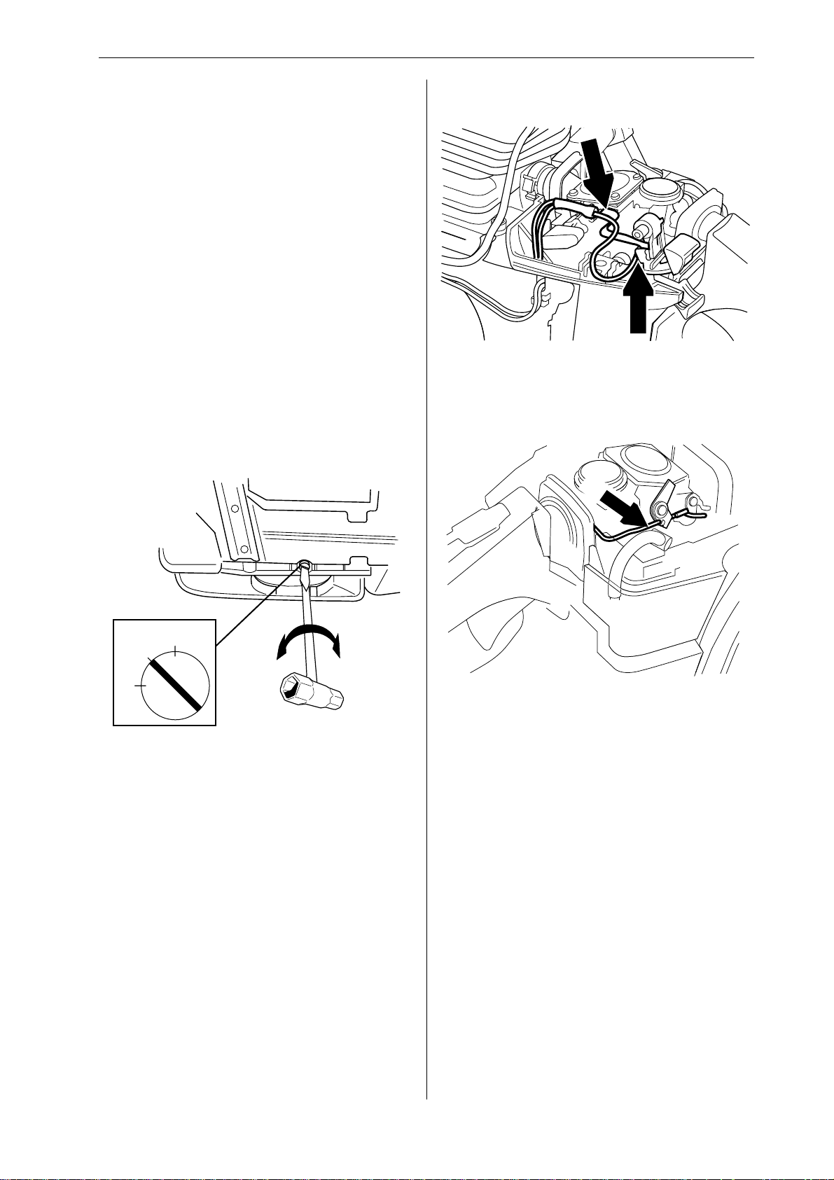
Adjustable oil pump – adjustment
Use a screwdriver or adjustable spanner to turn the
adjuster screw on the pump. Turning the screw
clockwise decreases the oil flow and turning it anticlockwise increases the oil flow.
Carburettor – removal
1
Remove the cylinder cover and air filter. Disconnect
the leads from the stop switch.
2
1
2
3
Recommended setting:
13–15" bar Min. setting
15–18" bar Midway setting
18–20" bar Max. setting
+
–
Disconnect the throttle pushrod from the carburettor by first carefully prising up the spring over the
end of the rod where it connects to the throttle
lever. Then press the throttle lever forwards while
pressing the throttle pushrod backwards and lifting
it off the lever. Withdraw the throttle pushrod from
the tank and lift it upwards without pulling it through
the rubber inlet manifold. Carefully release the
carburettor assembly from its rubber mountings.
www.mymowerparts.com
English – 29
Page 31
For Husqvarna Parts Call 606-678-9623 or 606-561-4983
Repair instructions
3
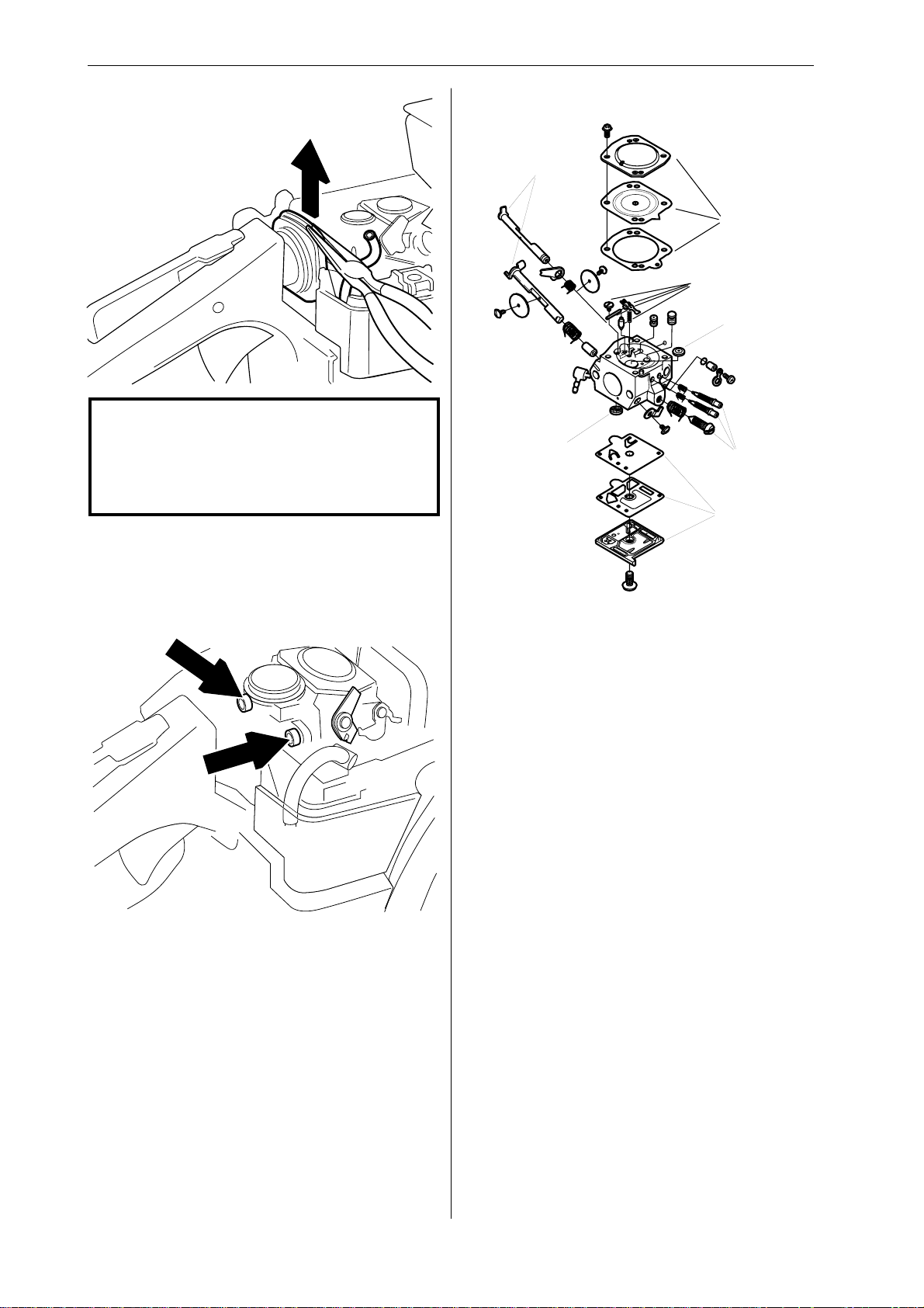
NOTE!
Do not use knurled pliers to disconnect or
reconnect the fuel hose. This could damage the hose and lead to leakage or
fracture.
Disconnect the fuel hose from the carburettor.
Remove the rubber inlet manifold, using pliers to
lift it upwards.
Carburettor – dismantling
7
1
2
6
4
5
3
4
Undo and remove the carburettor bolts. Lift off the
carburettor.
The item numbers in the diagram refer to the steps
below (1–7).
1
Remove the cover from the metering unit and
carefully remove the metering diaphragm and
gasket.
2
Undo the screw and take out the needle valve,
together with the lever arm, spindle and spring.
3
Remove the cover from the pump unit and carefully
remove the gasket and pump diaphragm.
4
Remove the fuel filter.
5
Remove the high, low and idling jet screws. (HDA
159A high and low jet screws are protected by
plastic caps which can be prised off with a screwdriver. Only on EPA, see appendix A.)
30 – English
6
Remove the plug by first drilling a hole in it and
then prising it out with a screwdriver or the like.
7
If necessary remove the throttle and choke valves,
and remove the spindles together with the lever
arms and springs.
www.mymowerparts.com
Page 32
For Husqvarna Parts Call 606-678-9623 or 606-561-4983
Repair instructions
Cleaning and inspection
Clean all the carburettor components in petrol. Use
an airline to dry off the petrol from all components.
Blow through all the channels in the carburettor
body and check that they are not blocked.
Check that:
• The gasket, pump diaphragm and metering
diaphragm are undamaged.
• There is no play in the throttle and choke valves.
• The needle valve and its lever arm are not worn.
• The fuel filter is undamaged.
• The tips of the high and low speed jet screws
are not damaged.
• The air intake duct is not cracked.
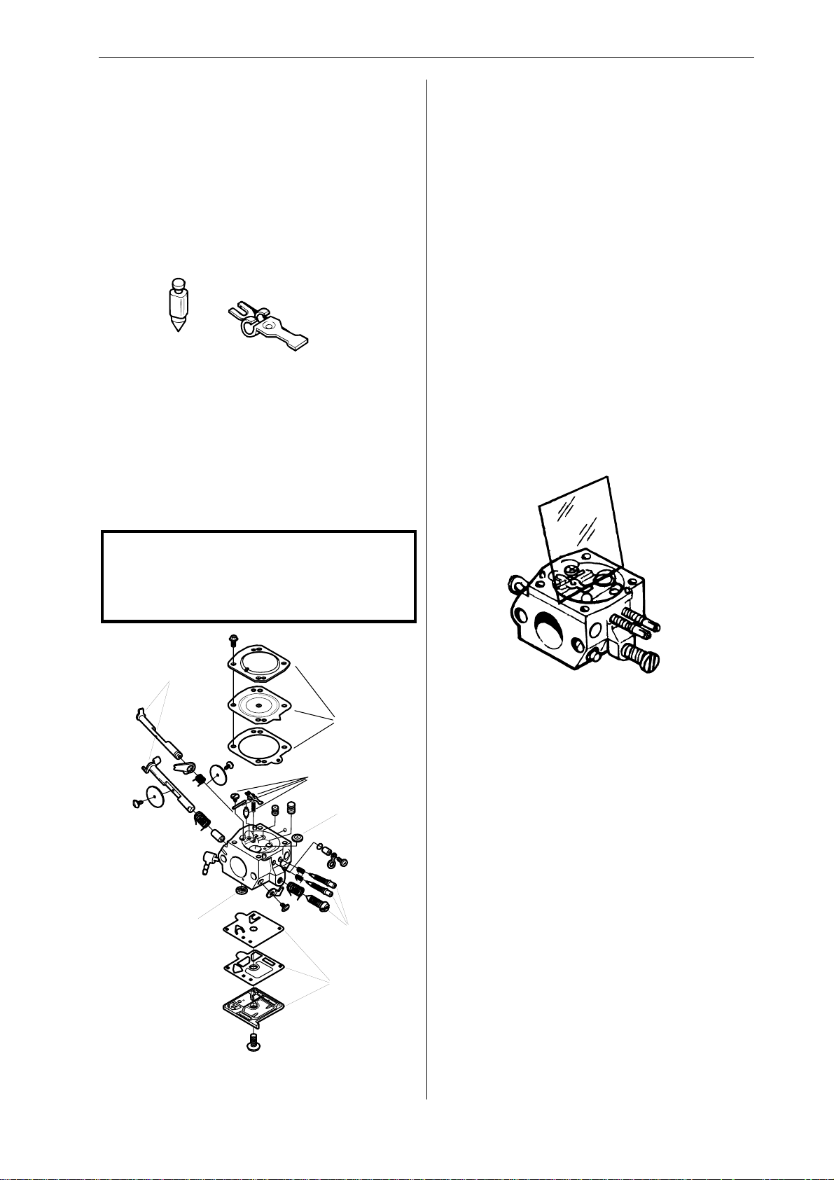
1
If the throttle and choke butterflies and their
spindles were removed, these must be refitted.
Lubricate the spindle bearings with light oil.
2
Insert the plug in the hole with the convex side
upwards and expand it by pressing downwards
with a drift.
3
Refit the high and low speed jet screws and
springs, plus the idling screw. Fit the plastic caps
over the high and low speed screws.
4
Fit the fuel filter, using the handle of a small screwdriver.
5
Fit the pump diaphragm, gasket and cover to the
pump unit.
6
Carburettor – reassembly
NOTE!
Cleanliness is very important when reas-
sembling the carburettor. Tiny particles of
dirt can cause operating problems.
7
1
2
6
Fit the needle valve with lever arm, spindle and
spring and tighten the screw.
Use a rule to check that the lever arm is level with
the cover face. If necessary, the lever arm can be
bent slightly.
7
Fit the metering diaphragm with its gasket and refit
the cover to the metering unit.
8
Carry out pressure testing.
4
5
3
The item numbers in the diagram refer to the steps
below (1–8).
www.mymowerparts.com
English – 31
Page 33
For Husqvarna Parts Call 606-678-9623 or 606-561-4983
Repair instructions
Carburettor – pressure testing
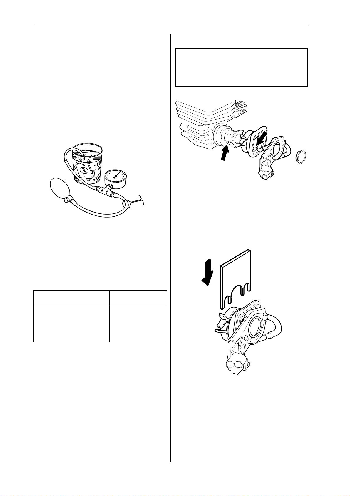
Pressure testing should be carried out with the
carburettor fully assembled. Testing should always
be carried out after the carburettor has been
repaired, but can also be performed for troubleshooting before dismantling.
Carry out the test as follows:
• Screw in the high and low speed jet screws and
back them off one turn.
• Connect pressure tester 502 50 38-01 to the
carburettor fuel inlet.
• Lower the carburettor into a beaker of water.
• Pump up the pressure to 50 kPa (0.5 bar) and
clamp the pump tube.
Carburettor – refitting
NOTE!
Cleanliness is very important when reas-
sembling the carburettor. Tiny particles of
dirt can cause operating problems.
1
Align the inlet manifold with the cut-out in the
carburettor flange and make sure the inlet manifold
is correctly seated. It is especially important to
ensure that the impulse tube is correctly seated in
the impulse channel on the cylinder. In order to
check this the cylinder must be removed, see
“Piston and cylinder – removal and fitting”.
Fit the support ring in the inlet manifold.
2
• There should be no leakage. If leakage occurs,
refer to the table below.
Leakage Fault lies in
Diffuser jets Needle valve
In impulse tube Pump diaphragm
Ventilation hole above
metering unit Control diaphragm
Fit stop plate 502 54 17-01 between the carburettor flange and the insulating plate.
32 – English
www.mymowerparts.com
Page 34
For Husqvarna Parts Call 606-678-9623 or 606-561-4983
Repair instructions
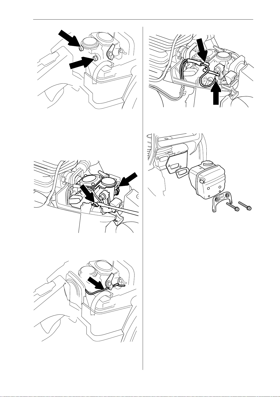
3
Fit the carburettor. Screw in the carburettor bolts
directly from behind, without lifting the carburettor
assembly. Tighten to a torque of 1–1.5 Nm. It is
important to hold the carburettor flange while
tightening the bolts to prevent the inlet manifold
from moving.
4
6
Connect the leads to the stop switch.
7
Push the rear carburettor mounting into its rubber
bushing using a small screwdriver. Remove stop
plate 502 54 17-01.
5
Connect the fuel hose to the carburettor. Refit the
throttle pushrod at the same time as the rubber
inlet manifold, press in the throttle pushrod so that
it engages in the carburettor and fit the spring.
Then refit:
• cooling plate
• gasket
• silencer, tighten bolts to a torque of 12–14 Nm
• silencer support, tighten bolts to a torque of 8–
10 Nm
• bark rest, tighten bolts to a torque of 8–10 Nm
• HT lead
• air filter
• cylinder cover
8
After pressure testing, re-tighten the silencer bolts
to a torque of 8–10 Nm.
www.mymowerparts.com
English – 33
Page 35
For Husqvarna Parts Call 606-678-9623 or 606-561-4983
Repair instructions
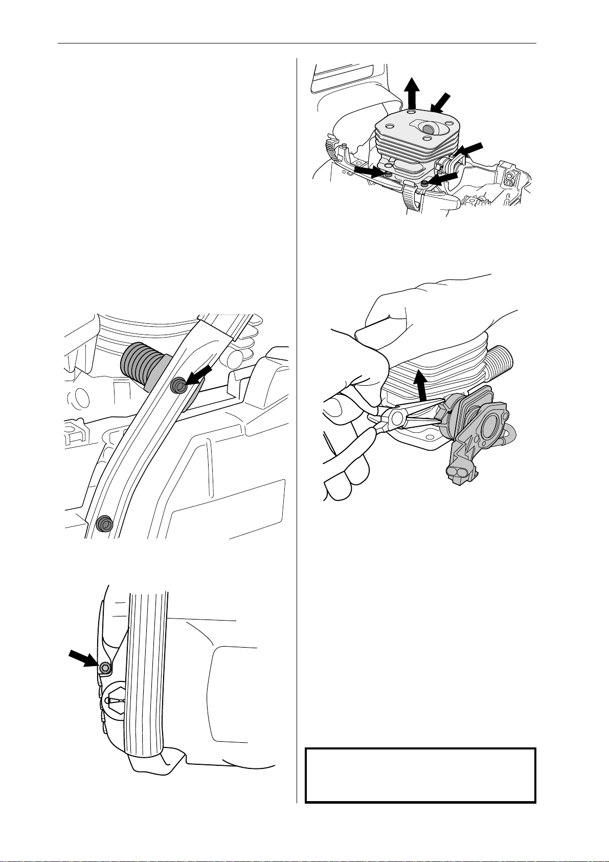
Air intake system – removal
The air intake system comprises:
• inlet manifold
• insulating plate with clip
• carburettor flange
• impulse hose
• support ring
1
Remove:
• cylinder cover
• air filter
• carburettor
• HT lead
2
4
Unscrew the four cylinder bolts. Lift up the cylinder
so that the intake system insulating plate is free of
the crankcase.
5
Unbolt the vibration damping spring between the
cylinder and hand grip.
3
Unscrew and remove the bolts from the silencer
support.
Free the insulating plate from the cylinder by
releasing the clamp using pliers. Remove the
complete air intake system.
6
Remove:
• support ring
• carburettor flange from the inlet manifold
• insulating plate
Cleaning and inspection
Clean and inspect all parts carefully. If there are
any cracks or other defects replace the damaged
parts with new ones. Alw ays use original parts.
NOTE! When replacing the impulse hose it must
not be lubricated with oil or grease.
NOTE!
When you replace the impulse hose do
not lubricate it with grease or oil.
34 – English
www.mymowerparts.com
Page 36
For Husqvarna Parts Call 606-678-9623 or 606-561-4983
Repair instructions
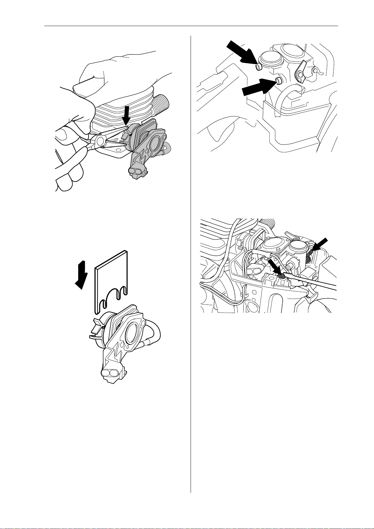
Air intake system – refitting
1
First fit the inlet manifold onto the cylinder. Then fit
the insulating plate and secure it to the cylinder
with the clamp. Check carefully that the impulse
tube is correctly seated in the impulse channel. Fit
the carburettor flange to the inlet manifold.
3
Refit the carburettor. Screw in the carburettor bolts
directly from behind without lifting the carburettor
assembly, tightening to a torque of 1–1.5 Nm. It is
important to hold the carburettor flange securely
when tightening the bolts to prevent the inlet
manifold from moving.
4
2
Position tool 502 54 17-01 between the carburettor
flange and the insulating plate.
Push down the rear carburettor mounting into the
rubber bushings using a small screwdriver. Remove tool 502 54 17-01.
5
Refit:
• cylinder, see ”Piston and cylinder - refitting”
• silencer support, tighten bolts to a torque of 8–
10 Nm
• bark rest, tighten bolts to a torque of 8–10 Nm
• air filter
• HT lead
• cylinder cover
6
After the test run retighten the silencer bolts to a
torque of 8–10 Nm
www.mymowerparts.com
English – 35
Page 37
For Husqvarna Parts Call 606-678-9623 or 606-561-4983
Repair instructions
Carburettor – adjustment
For instructions on adjusting the EPA carburettor
see appendix A.
Adjusting the carburettor involves adjusting the
engine to the local conditions e.g. climate, altitude,
fuel and type of two-stroke oil.
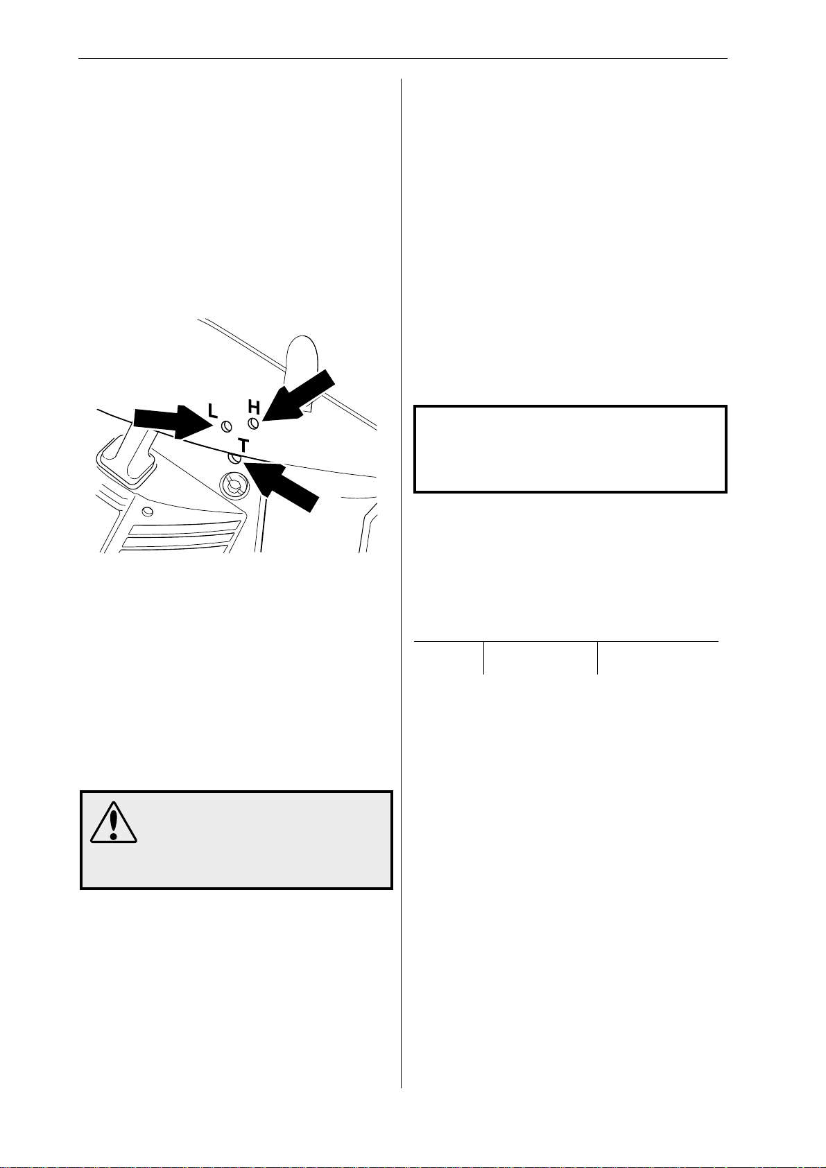
The carburettor is equipped with three adjustment
options.
L = Low speed jet
H = High speed jet
T = Idling adjustment screw
Basic settings and running in
During testing at the factory the carburettor is
adjusted to the basic factory settings.
The factory settings are H = 1 turn and L = 1 turn.
To ensure that engine components receive
adequate lubrication (running in) the carburettor should be set to a somewhat richer fuel
mixture for the chainsaw’s first 3-4 running
hours. This is done by adjusting the maximum
speed to 6-700 rpm less than the recommended
maximum speed.
If it is not possible to check the maximum speed
with a tachometer then the H jet should not be set
to a weaker mixture than the basic factory setting.
The recommended maximum speed must not
be exceeded.
NOTE!
If the chain turns at idling speed, the T
screw should be turned anti-clockwise
until the chain stops.
The L and H jets adjust the fuel flow to match the
airflow that the throttle valv e opening allo ws.
Turning them clockwise makes the fuel/air mixture
weaker (less fuel in relation to the amount of air)
and turning them anti-clockwise makes the fuel/air
mixture richer. A weak mixture increases the
engine speed and a rich mixture decreases the
engine speed.
The T screw controls the throttle position when
idling. Turning the T screw clockwise gives faster
idling; turning it anti-clockwise lowers idling speed.
WARNING!
The guide bar, chain and clutch
cover must be fitted before the
saw is started, otherwise the
clutch may fly off and cause injury.
Fine adjustment
Once the chainsaw is “run in” the carburettor
should be readjusted. First adjust the L jet screw,
then the idling screw T and finally the H jet screw.
The recommended engine speeds are as follows:
Model Max revs Idle revs
357XP/G 14 000 rpm 2 700 rpm
359/G 13 500 rpm 2 700 rpm
Basic requirements
• Before making any adjustments the air filter
should be clean and the cylinder cover should
be in place. If the carburettor is adjusted with a
dirty air filter, the mixture will be too weak next
time the air filter is cleaned. This can cause
serious engine damage.
• Carefully screw in the L and H jets fully, then
back them off 1 turn. The carburettor now has
the settings H = 1 and L = 1.
• Start the chainsaw and allow it to warm up for 10
minutes.
36 – English
• Place the saw on a flat surface so that the guide
bar is pointing away from you and the guide bar
and chain are not touching the surface.
Low speed jet L
• Find the highest idling speed by slowly screwing
the L screw in and then out again.
• When the highest speed has been found, screw
out the L screw 1/8 - 1/4 turn.
www.mymowerparts.com
Page 38
For Husqvarna Parts Call 606-678-9623 or 606-561-4983
Repair instructions
Fine adjustment of idling speed T
• The idling speed is adjusted using the screw
marked T .
• If adjustment is necessary, screw in the idling
screw T until the chain starts to turn. Then screw
it out until the chain stops moving.
• The idling speed is correctly set when the
engine runs smoothly in all positions and there
is a clear margin to the speed at which the chain
starts to move.
High speed jet H
• The high speed jet H influences the saw power
output and engine speed. If the H jet is set too
weak the saw will over-rev, which could cause
engine damage.
• Run the saw at full throttle for about 10 seconds.
H=1.
• Then screw out the H screw 1/4 turn. H=1 1/4.
• Run the saw again at full throttle for about 10
seconds and listen to the difference in the engine
note. Repeat this procedure again with the H
screw screwed out another 1/4 turn. H=1 1/2.
• You have now run the saw at settings H ± 0, H =
+1/4 and H = +1/2 from the factory setting. At full
throttle the engine will sound different at each
setting.
• The H screw is correctly adjusted when the saw
“burbles” a little at full throttle without any load.
• If there is a lot of smoke from the silencer and
the saw does not run smoothly then the setting
is too rich.
• Screw in the H screw to the setting that sounds
right.
Fuel tank – removal
WARNING!
The fuel used in chainsaws is
harmful if inhaled, may cause
skin irritation and is highly flammable.
1
Empty the fuel tank.
2
Remove the following:
• cylinder cover
• air filter
• clutch cover
• chain and guide bar
• starter assembly
• cable guide
3
Disconnect the fuel hose from the carburettor.
4
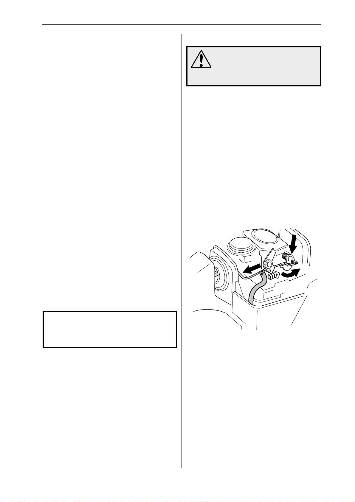
A
C
B
NOTE!
For optimum adjustment, a tachometer
should be used. The recommended
maximum speed should not be exceeded.
Carburettor – correct adjustment
• When the carburettor is correctly adjusted the
saw should accelerate without hesitation and the
engine will burble a little at full throttle without
any load.
• The chain must not turn when idling.
• If the L screw is set too weak this can make the
saw difficult to start and cause poor acceleration.
• If the H screw is set too weak the saw will
produce less power, poor acceleration and there
is a risk of engine damage.
• If either the L or H screws are set too rich it will
cause acceleration problems or too low working
speed.
Disconnect the pushrod from the carburettor by
first carefully prising up the spring over the end of
the rod, where it connects to the throttle lever (A).
Then press the throttle lever forwards (B) while
pressing the throttle pushrod backwards (C) and
lifting it off the lever. Withdraw the throttle pushrod
from the tank and lift it upwards without pulling it
through the rubber inlet manifold.
English – 37
www.mymowerparts.com
Page 39
For Husqvarna Parts Call 606-678-9623 or 606-561-4983
Repair instructions
5
Cleaning and inspection
Carefully check that:
• there are no leaks from the fuel tank
• there are no leaks from the tank filler cap
• the fuel hose is undamaged and free from wear
• the fuel filter is not clogged
• the tank vent is not blocked or leaking
• the vibration damping springs and stops are not
damaged
Replacing the fuel filter
NOTE!
Do not use knurled pliers to disconnect or
reconnect the fuel hose. This could
damage the hose and lead to leakage or
fracture.
1
First remove the old fuel filter from the tank unit
using special tool 502 50 83-01.
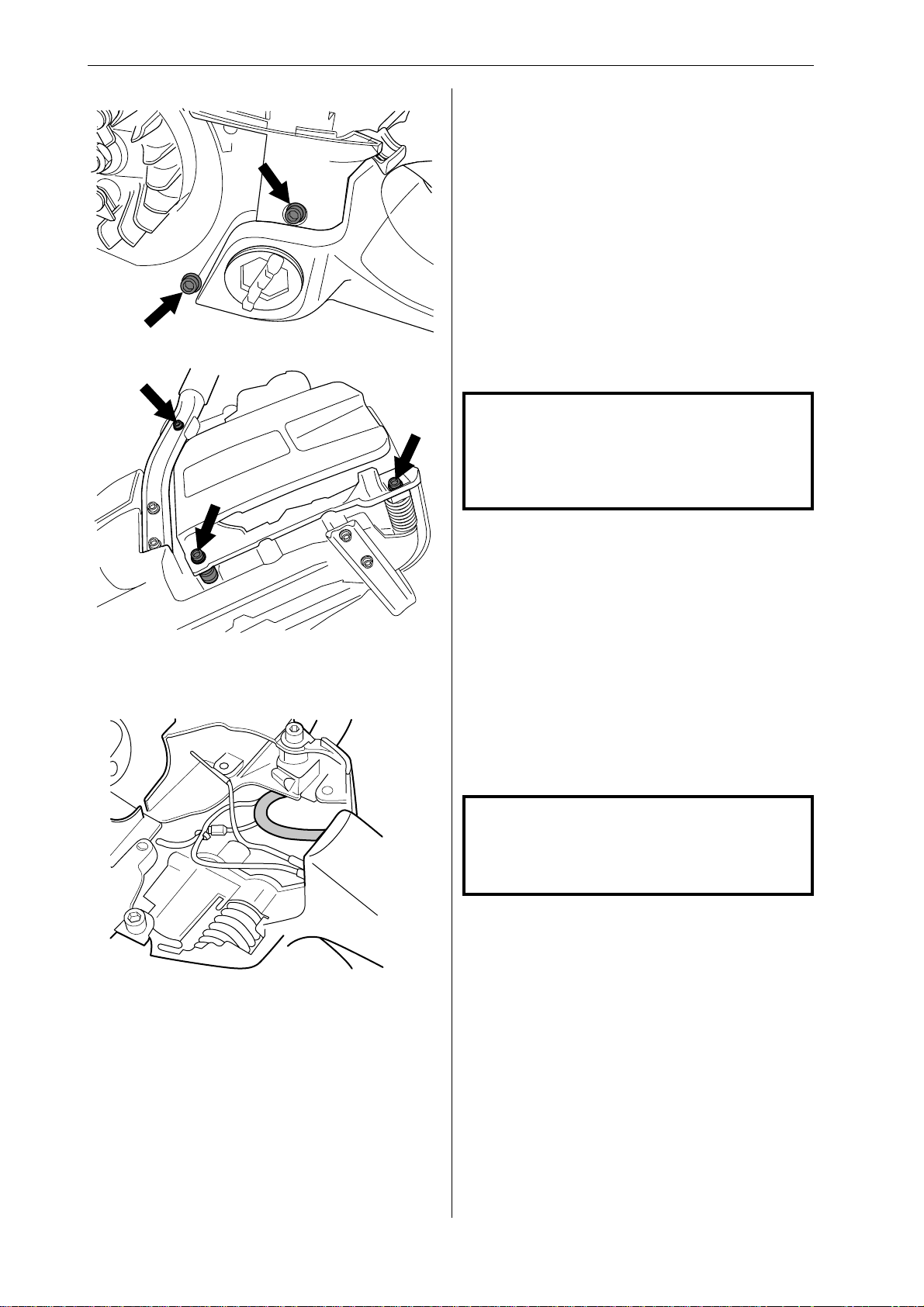
Unscrew the two stops and three vibration damping springs from the sides of the saw.
6
Disconnect and remove the fuel hose from the
crankcase.
2
Pull the fuel hose out of the tank and pull off the
filter.
3
Fit the new fuel filter and feed the fuel hose back
into position.
Replacing the fuel hose
NOTE!
Do not use knurled pliers to disconnect or
reconnect the fuel hose. This could
damage the hose.
1
Before replacing the fuel hose, measure the length
of hose between the crankcase and carburettor
and between the tank and crankcase. The correct
hose length between the tank and crankcase is 43
mm (1.69 inches). The correct hose length between the crankcase and carburettor is 53 mm
(2.09 inches).
38 – English
2
Remove the fuel hose from the fuel tank using tool
502 50 83-01. Trim off 5 mm (0.20 inches) from the
mitred end of the hose. Fit the fuel filter and
reinsert the hose in the tank.
www.mymowerparts.com
Page 40
For Husqvarna Parts Call 606-678-9623 or 606-561-4983
Repair instructions
Tank vent – testing
1
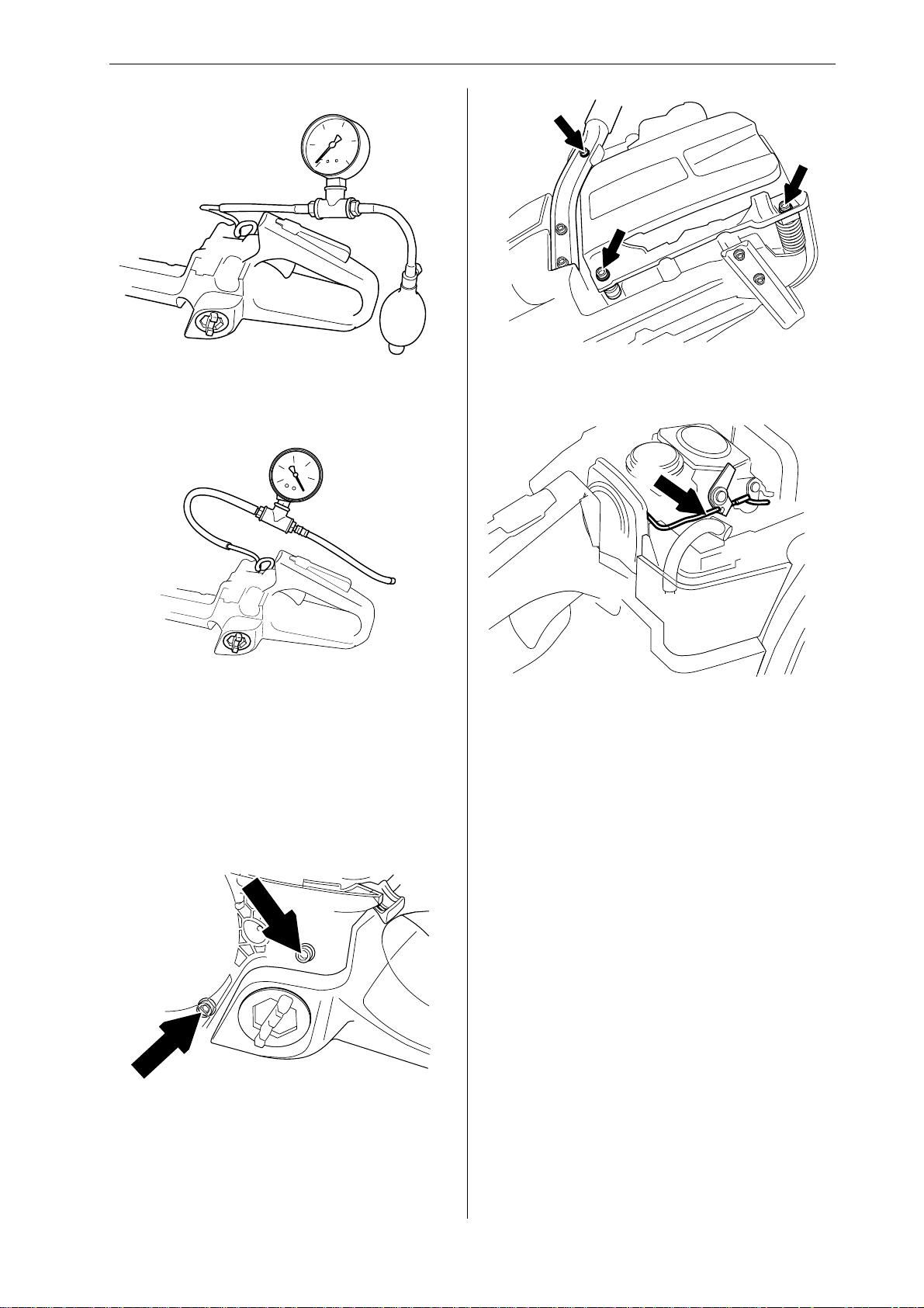
Connect pressure gauge 502 50 38-01 to the fuel
hose. Pump the pressure up to 50 kPa (0.5 bar).
The pressure should drop to 20 kPa (0.2 bar)
within 60 seconds.
2
3
Fit the throttle pushrod in the tank and connect it to
the carburettor. Refit the spring.
4
Use gauge 502 50 37-01 to measure vacuum.
Readings should be as follows: the vacuum
should increase from 30 to 15 within 30 seconds.
If readings are outside this range the vyon plugs
must be replaced.
Fuel tank – refitting
1
Insert the fuel hose into the carburettor chamber.
Refit the fuel tank.
2
Bolt the front vibration damping spring into position, followed by both stops and the remaining two
vibration damping springs. Tighten to a torque of
2–3 Nm. Check that both vibration damping
springs and the stops are correctly seated on the
crankcase. Incorrect fitting may result in higher
vibration levels.
Connect the fuel hose to the carburettor . Check that
the hose is not twisted and is not too long so that it
gets trapped between the crankcase and tank. The
correct hose length between the tank and crankcase
is 43 mm (1.69 inches). The correct hose length
between the crankcase and carburettor is 53 mm
(2.09 inches) excluding the mitred section.
5
Connect the fuel hose to the carburettor.
6
Then refit:
• cable guide
• starter assembly (2.5–3 Nm)
• chain and guide bar
• clutch cover
• air filter
• cylinder cover
www.mymowerparts.com
English – 39
Page 41
For Husqvarna Parts Call 606-678-9623 or 606-561-4983
Repair instructions
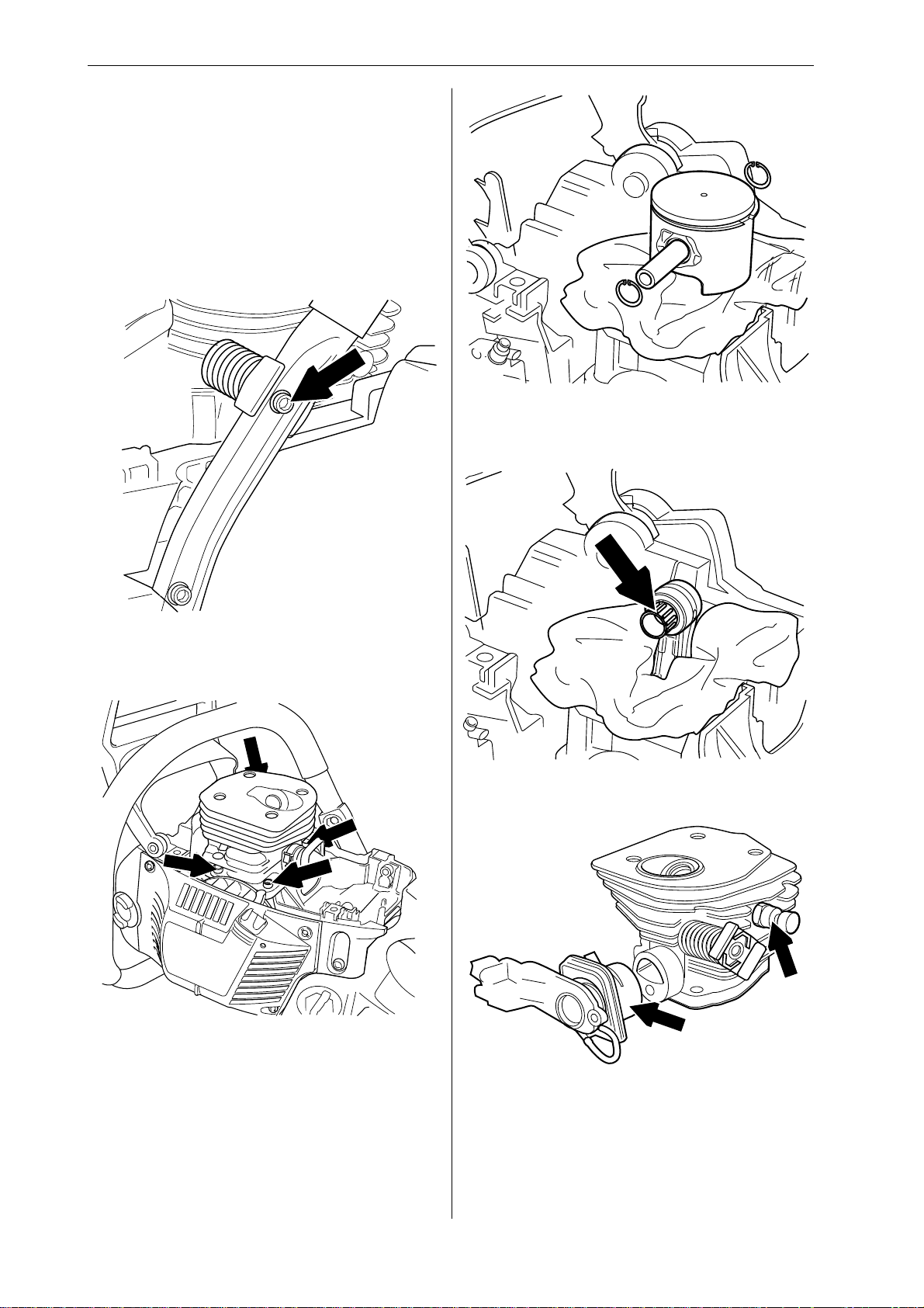
Piston and cylinder – removal
1
Remove:
• cylinder cover
• carburettor, see ”Carburettor - removal”
• silencer
• spark plug.
2
5
Remove the circlips from the ends of the gudgeon
pin and press it out. Then lift off the piston.
6
Unbolt the vibration damping spring from the hand
grip.
3
Undo the four cylinder bolts and lift the cylinder off
carefully.
4
Cover the opening in the crankcase.
Remove the bearing from the little end of the
connecting rod.
7
If replacing the cylinder:
Unscrew the decompression valve. Remove the air
intake system, see ”Air intake system - removal”.
40 – English
www.mymowerparts.com
Page 42
For Husqvarna Parts Call 606-678-9623 or 606-561-4983
Repair instructions
Cleaning and inspection
Clean all the components, scraping off all traces of
old gasket and carbon from the following places:
• Piston crown
• Top of the cylinder bore
• Cylinder exhaust port
• Decompression valve channel
• Cylinder base and/or crankcase
Check the following:
• The surface coating of the cylinder is not worn
through, especially in the upper part of the
cylinder.
• The cylinder is free from score marks and areas
of wear.
• The piston is free from score marks. Small
scratches can be polished out with fine emery
paper.
• The piston ring is not burnt into its groove.
2
Pump up the pressure to 80 kPa (0.8 bar).
3
Wait 30 seconds.
4
The pressure should not be less than 60 kPa
(0.6 bar).
Piston and cylinder – refitting
1
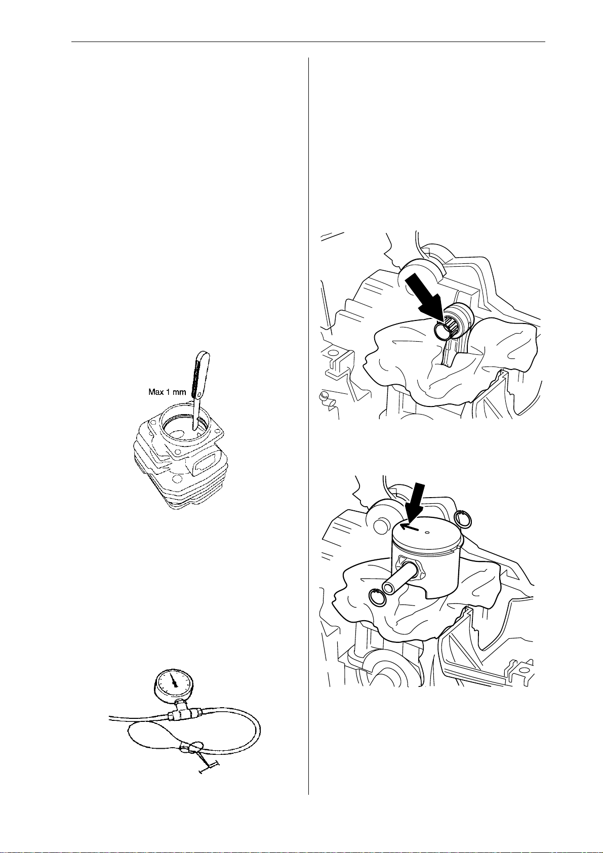
• Measure piston ring wear. This should not
exceed 1 mm. Use the piston to push down the
piston ring.
• The needle roller bearing is undamaged.
• The inlet manifold is undamaged.
• Pressure test the decompression valve.
• Also refer to Jonsered’s Analysis guide for piston
failures, art. no. 108 07 01-01.
Decompression valve – pressure
testing
1
Lubricate the little end bearing with two-stroke oil
and insert it in the connecting rod.
2
Fit the piston with the arrow pointing towards the
exhaust port. Push in the gudgeon pin and fit the
circlips. If replacing the cylinder, fit the decompression valve, tightening to a torque of 12–14 Nm.
Connect tool 502 50 38-01 to the decompression
valve.
www.mymowerparts.com
English – 41
Page 43
For Husqvarna Parts Call 606-678-9623 or 606-561-4983
Repair instructions
3
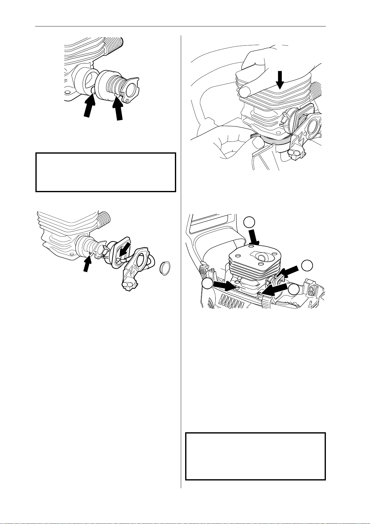
Fit the inlet manifold 503 86 63-01 to the cylinder.
Check that the impulse tube is correctly seated in
the impulse channel.
NOTE!
It is very important that there are no leaks
in the inlet system, otherwise the engine
may seize.
4
6
Fit a new cylinder base gasket. Compress the
piston ring with tool 502 50 70-01 and lower the
cylinder over it carefully.
7
Press the insulating plate 503 86 62-01 onto the
cylinder. Check that the impulse tube connected to
the insulating plate is seated correctly in the inlet
manifold and lock the clamp over the manifold.
5
Lubricate the piston ring and piston with two-stroke
oil.
1
4
3
2
Fit the cylinder bolts, tightening them in diagonal
pairs to a torque of 8–10 Nm.
8
Pressure test the cylinder.
9
Refit:
• spark plug, tighten to a torque of 15 Nm
• carburettor, see ”Carburettor - refitting”.
42 – English
• silencer, tighten to a torque of 8–10 Nm
• cylinder cover
NOTE!
If a new piston or cylinder has been fitted
the saw must be run for the first 3–4
hours with carburettor adjusted to the
factory settings.
www.mymowerparts.com
Page 44
For Husqvarna Parts Call 606-678-9623 or 606-561-4983
Repair instructions
Cylinder – pressure testing Crankcase and crankshaft –
dismantling
1
Remove the following:
• guide bar and chain
• clutch cover
• cylinder cover
• starter assembly, see ”Starter assembly removal”
• ignition system, see ”Ignition module/flywheel removal”
• generator, see ”Replacing the generator”
• centrifugal clutch, see ”Centrifugal clutch removal”
• oil pump, see ”Oil pump - removal”
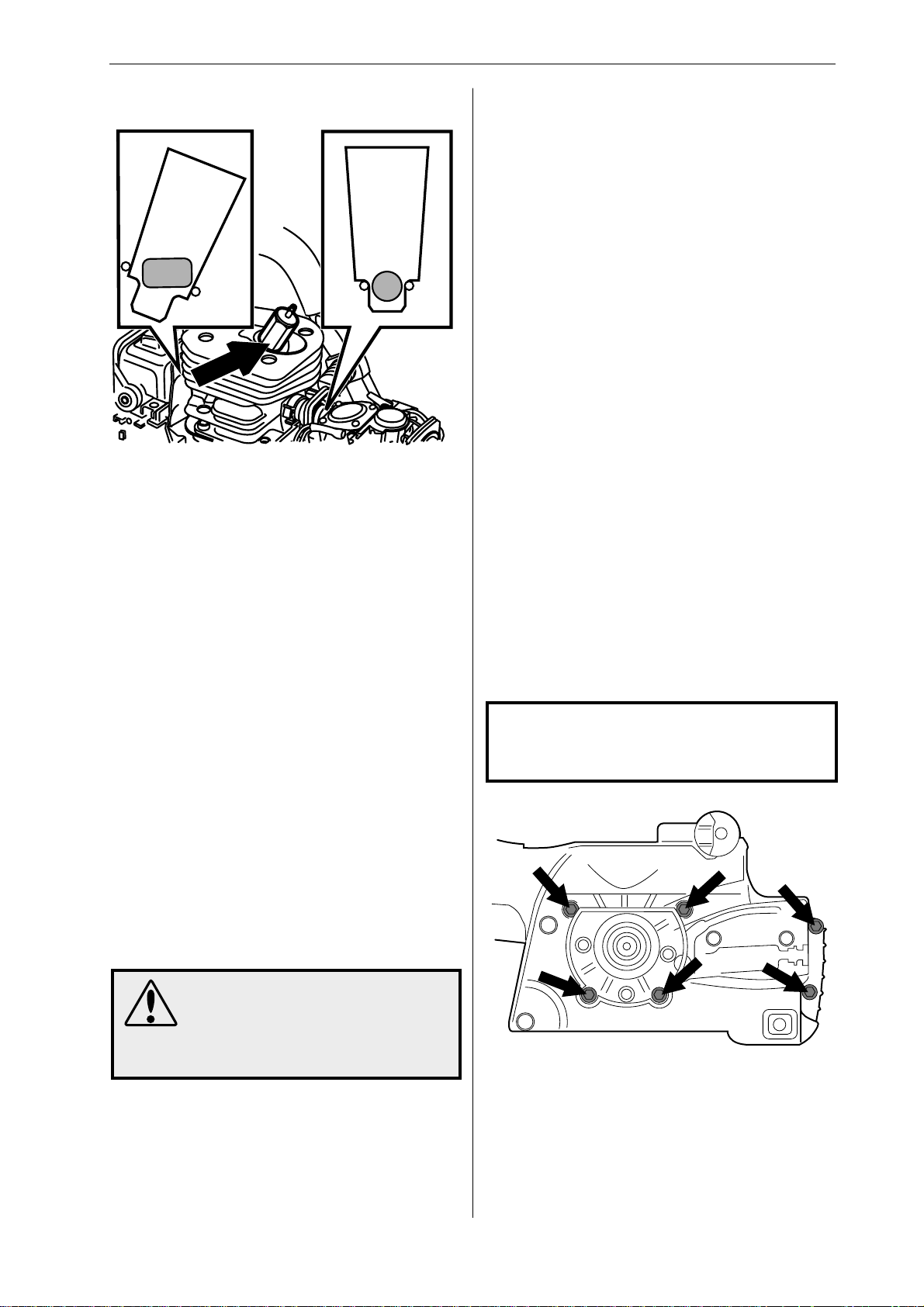
• Loosen the carburettor bolts so that the carburettor can be moved back about 4 mm. Insert
cover plate 502 54 11-02 between the carburettor and the carburettor flange. Tighten the
carburettor bolts to a torque of 1–1.5 Nm.
• Loosen the silencer bolts so that the silencer
can be moved back about 4 mm. Insert cover
plate 502 54 11-02 between the silencer and the
exhaust flange on the cylinder flange. Tighten
the silencer bolts to a torque of 8–10 Nm.
• Unscrew and remove the spark plug. Screw in
pressure test nipple 503 84 40-02. Connect tool
502 50 38-01 to the nipple. The decompression
valve must be closed. For instructions on testing
the decompression valve see ”Decompression
valve - pressure testing”.
• Pump up the pressure to 80 kPa (0.8 bar).
• Wait 30 seconds.
• The pressure should not be less than 60 kPa
(0.6 bar).
• Remove the cover plates from the silencer and
carburettor, tighten the bolts to the specified
torque. Remove the pressure test nipple 503 84
40-02 and refit the spark plug.
• bark rest
• chain tensioner
• throttle pushrod
• carburettor, see ”Carburettor - removal”
• carburettor base
• silencer, see ”Silencer - removal”
• piston and cylinder, see ”Piston and cylinder removal”
• fuel tank, see ”Fuel tank - removal”
NOTE!
Take care to prevent dirt or foreign parti-
cles getting into the bearings.
2
WARNING!
After pressure testing the cylinder, check that the inlet manifold
is seated correctly, otherwise the
saw may be damaged.
www.mymowerparts.com
Unscrew the 6 bolts that hold the crankcase
together.
English – 43
Page 45
For Husqvarna Parts Call 606-678-9623 or 606-561-4983
Repair instructions
3
WARNING!
Take care not to burn yourself
when the crankcase is hot. Wear
protective gloves.
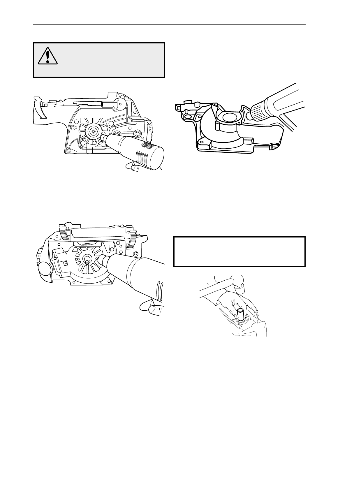
Split the crankcase by heating the flywheel side of
the crankcase with a hot air gun and tapping gently
on the crankshaft. Avoid heating the frame bearing
and crankshaft.
4
Crankshaft bearings – replacement
If the crankshaft bearings are to be replaced they
must be pulled off the crankshaft using puller 504
90 90-02. The new bearings must be shrunk-fit into
the crankcase using a hot air gun. Heat the crankcase half to around 130°C and fit the new bearing.
The new bearings must be shrunk-fit into the
crankcase using a hot air gun.
Cleaning and inspection
Clean and inspect all parts carefully.
Sealing ring – replacement
Remove the sealing ring from the crankcase using
a small screwdriver.
Free the crankshaft by heating the clutch side of
the crankcase.
NOTE!
Take care to avoid damaging the crank-
case.
To fit the sealing ring use the sleeve that is supplied with 502 50 30-16.
The end with the half moon is used for the sealing
ring on the clutch side, which must be fitted flush
with the surface of the crankcase.
The other end of the sleeve is used to fit the
sealing ring on the flywheel side and ensures that
the sleeve is fitted at the correct depth, 1.8 mm.
Lubricate the sealing rings with oil.
44 – English
www.mymowerparts.com
Page 46
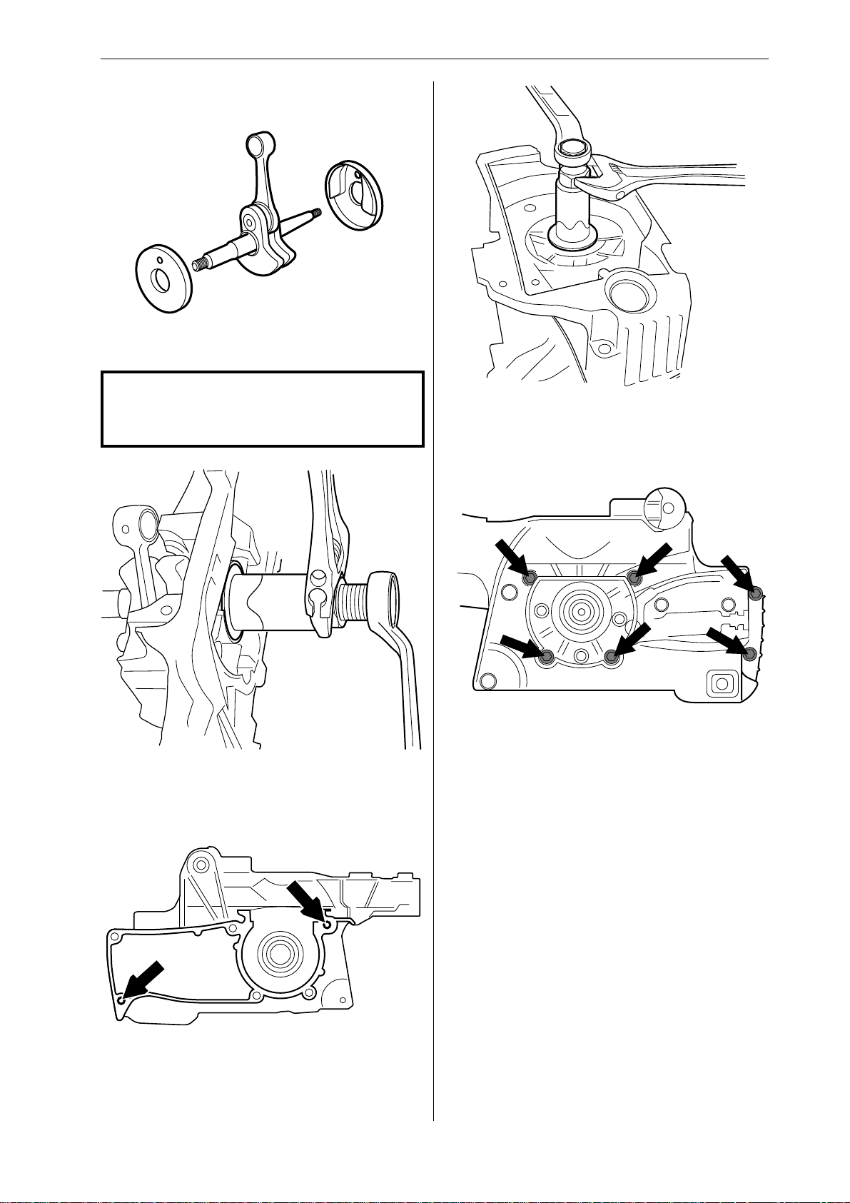
For Husqvarna Parts Call 606-678-9623 or 606-561-4983
Repair instructions
Crankcase and crankshaft –
reassembly
1
357 only:
Fit the cups on the crankshaft.
NOTE!
It is important that the cups are fitted over
the counterweights.
2
4
Place the flywheel side of the crankcase over the
crankshaft and pull the two crankcase halves
together using assembly tools 502 70 84-01 and
502 50 30-16.
5
Hold the clutch side of the crankcase in a vice. Pull
the crankshaft into its bearing using assembly tools
502 50 30-16.
3
Check that the guide pins are in place. Fit a new
gasket to the mating surface of the clutch side of
the crankcase.
Fit and tighten the six crankcase bolts to a torque
of 8–10 Nm. Check that the crankshaft rotates
freely.
www.mymowerparts.com
English – 45
Page 47
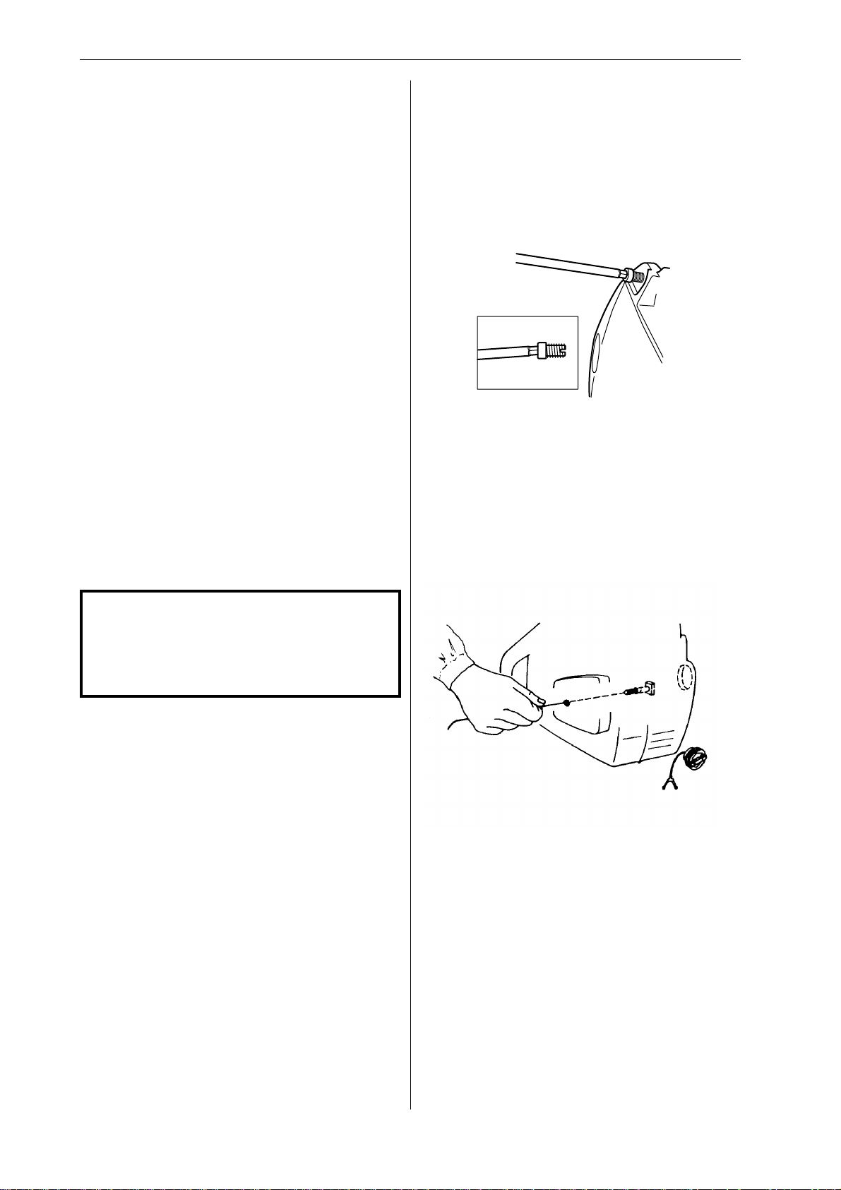
For Husqvarna Parts Call 606-678-9623 or 606-561-4983
Repair instructions
Refit the following parts:
• bark rest, 8-10 Nm
• oil pump, 3-4 Nm, see ”Oil pump - refitting”
• chain tensioner
• centrifugal clutch, min 20 Nm, see ”Centrifugal
clutch - refitting”
• fuel tank, see ”Fuel tank - refitting”
• piston and cylinder, see ”Piston and cylinder refitting”
• generator, see ”Replacing the generator”
• carburettor base, 3-4 Nm
• carburettor, 1-1,5 Nm, see ”Carburettor - refitting”
• throttle pushrod
• silencer, 12-14 Nm, see ”Silencer - refitting”
• ignition system, 8-10 Nm, see ”Ignition module
and flywheel - refitting
• starter assembly, 2,5-3,5 Nm, see ”Starter
assembly - refitting
• cylinder cover
• clutch cover
Repairing damaged threads
A repair kit, 503 27 33-01, is available for repairing
damaged threads.
First drill out the hole using:
6.1 mm drill bit for magnesium crankcase
Then screw in the thread insert using a suitable
bolt and spanner.
Guide bar bolts – replacement
1
Drain the oil tank.
2
Knock through the old guide bar bolt so that it falls
into the oil tank.
• guide bar and chain
NOTE!
If a new crankshaft has been fitted the
saw must be run in for 3-4 hours with the
carburettor adjusted to the factory
settings.
3
Remove the bolt from the oil tank.
4
Fasten a steel wire to the thread of the new bolt,
feed the steel wire into the oil tank and out through
the bolt hole in the crankcase.
5
Pull the steel wire until the bolt comes out through
its hole.
6
Pull through the bolt with its nut. Place a spacer
between the nut and crankcase.
46 – English
7
Check that the square shoulder of the bolt is
correctly seated in the recess in the crankcase.
8
Refill with chain oil.
www.mymowerparts.com
Page 48

For Husqvarna Parts Call 606-678-9623 or 606-561-4983
Appendix A
Carburettor – EPA models
Basic adjustment for EPA carburettors
After replacing the carburettor or high speed and/or
low speed needle on an EPA (The US Environmental Protection Agency) certified product a basic
adjustment must be carried out as described below
in order to meet the EPA-requirements. This to
achieve as low emissions as possible. This instruction is made for USA only.
On EPA carburettors both the H and L-needles are
fitted with caps to prevent the chain saw operator
from changing the adjustment above EPA standard. The caps can be removed to achieve richer or
leaner adjustments. To set the needles correctly an
adjustment sleeve
them in maximum allowed setting. When correctly
set the caps must be fixed on the needles. The
adjustment sleeve then can be removed.
NOTE! Before making any adjustments the
following must be done.
• Mount, for this model, approved bar & chain
combination for a 16" bar (see Technical data in
the Operator's manual).
• The chain should not be tensioned more than
that it remains ~0.2 inches to the bar.
• Mount a new air filter.
is fitted over the caps to lock
6. Adjust the H-needle to a top speed of "B" rpm.
Model 357XP B= 14 500
Model 359 B= 13 000
7. Check that the H-cap is still adjusted to its
richest setting. (Turned counterclockwise to
stop). NOTE! The H-needle must not rotate!
8. Gently knock the H-cap into position. Use a 5
mm/0.2 inch mandrel (for ex. the locking pin for
the bevel gear ref.no. 502 02 61-03).
This is a basic carburettor adjustment. Further fine
adjustments, within the limits the caps allow, may
be necessary to achieve optimum performance.
See the Operator´s manual.
Replacement of the L-needle
1. Take off the cap from the L-needle e.g. a pair of
cutting pliers and unscrew the needle.
2. Screw the new L-needle to the bottom and then
turn it counterclockwise 1 1/2 turns.
3. Press a new L-cap on the L-needle to the first
stop, which means that the cap is not fixed to
the needle, it should rotate independently.
4. Adjust the L-cap to the richest position (turned
counterclockwise to stop) without turning the
needle.
Replacement of the H-needle or complete carburettor
1. Screw the new H-needle to the bottom and turn
it counterclockwise "3/4" turns.
2. Check that:
• The H-cap is adjusted to its richest setting.
(Turned counterclockwise to stop.)
• The cap is not fixed to the needle, it should
rotate independently. Adjust the L-cap to a
center position ( 1/4 turn counterclockwise =
minimum, 1/4 turn clockwise = maximum).
3. Start the engine. If necessary, adjust the idling
speed with the T-screw until the chain stops.
4. Adjust the H-needle to give a top speed of "A"
rpm.
Model 357XP A= 13 500
Model 359 A= 12 500
Use a narrow blade screwdriver (Ref.no. 531 00
48-63) and insert it through the hole in the cap.
(max. blade width 2 mm/0.08 inch).
5. Let the engine run at 13 000 rpm ~1 minute,
until warm.
5. Let the engine run at ~"C" rpm app. 1 minute
until warm and then let it run on idle.
Model 357XP C= 13 500
Model 359 C= 12 500
6. Adjust the idle speed to 2 700 rpm.
7. Adjust the L-needle until the highest possible
idling speed is achieved and then run the Lneedle 1/2 turn counterclockwise. Use a narrow
blade screw-driver w. ref.no. 531 00 48-63 and
insert through the hole in the cap (max. blade
width 2 mm/0.08 inch).
NOTE! If the chain rotates, turn the idling
speed screw (T) counterclockwise until the
chain stops.
8. Check that the L-cap is still adjusted to its
richest position. (Turned counterclockwise to
stop). NOTE! The L-needle must not rotate!
9. Gently knock the L-cap into position. Use a 5
mm/0.2 inch mandrel (for ex. the locking pin for
the bevel gear ref.no. 502 02 61-03).
This is a basic carburettor adjustment. Further fine
adjustments, within the limits the caps allow, may
be necessary to achieve optimum performance.
See the Operator´s manual.
www.mymowerparts.com
English – 47
Page 49

Page 50

For Husqvarna Parts Call 606-678-9623 or 606-561-4983
Husqvarna
Printed in U.S.A.
www.mymowerparts.com
 Loading...