

Page 1

For Husqvarna Parts Call 606-678-9623 or 606-561-4983
Workshop manual
Rider 11, Rider 13,
Rider 11 Bio, Rider 13 Bio,
Rider 16
www.mymowerparts.com
English
Page 2

For Husqvarna Parts Call 606-678-9623 or 606-561-4983
www.mymowerparts.com
Svenska – 31
Page 3

For Husqvarna Parts Call 606-678-9623 or 606-561-4983
Workshop manual
Rider 11, Rider 13
Rider 11 Bio, Rider 13 Bio
Rider 16
Contents
Safety regulations ............................................... 2
General instructions ......................................... 2
Special instructions .......................................... 2
Special tools ........................................................3
Technical data ..................................................... 4
Tightening moments.........................................4
Play .................................................................. 4
Mowing deck .................................................... 5
Control points ................................................... 5
Delivery and dealer service ................................ 7
Maintenance schedule ..................................... 9
Delivery measures ............................................ 10
To our dealer .................................................. 10
Packaging and unpacking .............................. 10
Parts enclosed in packaging .......................... 10
Battery ............................................................ 11
Steering wheel ............................................... 12
Tow plate ........................................................ 12
Oil levels ........................................................ 12
Wheels ........................................................... 13
Checking and adjusting of the mowing
deck’s ground pressure and parallelism ........ 13
Test running ................................................... 14
Speed regulator ............................................. 15
Administration ................................................ 15
Design and function.......................................... 16
General .......................................................... 16
Serial number ................................................. 17
Engine ............................................................ 18
Steering .......................................................... 19
Driving ............................................................ 20
Mowing deck .................................................. 20
Reparation instructions .................................... 23
Removing engine ........................................... 23
Replacing engine ........................................... 25
Fuel tank ........................................................ 27
Changing engine oil ....................................... 28
Checking and adjusting steering wires .......... 28
Replacing steering wires ................................ 29
Removal/installation of steering axle ............. 29
Removal/installation of wire wheel ................. 30
Checking and adjusting brake wire ................ 31
Checking and adjusting gear control .............. 32
Checking and adjusting freewheel clutch ....... 32
Checking and adjusting throttle control .......... 33
Replacing articulated steering bearing ........... 33
Removal of swing axle ................................... 35
Replacing bushings ........................................ 35
Installation of swing axle ................................ 36
Removal/installation of gear box .................... 37
Removal/installation of hydrostatic
transmission ................................................... 37
Replacing hydrostat. trans. axle seals ........... 38
Input axle .................................................. 38
Outgoing axles ..........................................39
Replacing hydrostatic transmission wire ........ 40
Bleeding hydrostatic transmission oil system 44
Adjustment of transmission neutral position .. 44
Transmission maintenance ............................ 45
Oil change ................................................. 45
Removal of belt .............................................. 46
Checking and adjusting cutting unit ground
pressure ......................................................... 47
Checking and adjusting parallelism of the
mowing deck .................................................. 47
Adjusting cutting height area .......................... 49
Adjusting cutting height .................................. 49
Removing the cutting unit .............................. 50
To leave the service position .......................... 51
Dismantling the cutting unit ............................ 52
Replacing cutting unit belts ............................ 53
Replacing belt on BioClip 103 and
Combi 103................................................. 53
Replacing belt on BioClip 90 ..................... 54
Belt replacement on mowing deck with
side- or rear discharge BioClip 112 and
Combi 112 ................................................. 54
Replacing breakpin ........................................ 55
Removal of blades with bearings ................... 55
Grinding and balancing of blades .................. 57
Electrical system ............................................... 58
Circuit diagram Rider 11 ................................ 58
Circuit diagram Rider 13 and Rider 13 Bio .... 59
Circuit diagram Rider 16 ................................ 60
Inspection of safety system ............................ 61
Troubleshooting chart
www.mymowerparts.com
English – 1
Page 4

For Husqvarna Parts Call 606-678-9623 or 606-561-4983
Safety regulations
General instructions
The workshop handbook is written for personnel who
are assumed to have general ride-on mower reparation and service know-how.
The workshop where the ride-on mower is repaired
should be equipped with safety devices in
accordance with local regulations.
No-one should attempt to repair the ride-on mower
without having first read and understood the contents
of this handbook.
The machine is tested and approved only with the
equipment originally provided or recommended by
the manufacturer.
The below-mentioned boxes are included in this
workshop handbook, as is appropriate.
WARNING!
The warning box indicates a
risk of injury to persons if the
instructions are not followed.
Special instructions
The fuel used in the ride-on mower has the
following hazardous characteristics:
• Toxic fluid and fumes
• Can cause eye and skin complaints
• Can cause breathing difficulties
• Highly flammable
When using compressed air, do not direct the
compressed air stream towards your, or anybody
else's, body. Air can be forced into the blood
stream, thereby constituting a danger to life .
Use eye protection when working with tensioned
springs.
Use hearing protectors when test driving.
After test driving, do not touch the silencer before it
has cooled down. Risk of burn injuries. This
especially applies if the ride-on mower is equipped
with a catalytic converter. If consumed, the lining on
and in the catalytic converter element is dangerous
to health. Use protective gloves when working with
the catalytic converter/silencer.
IMPORTANT INFORMATION
This box indicates a risk of damage to the
material if the instructions are not
followed.
The blades are sharp and can cause cutting
injuries. Always use protective gloves when you are
handling the blades.
Use protective glasses when working with the
mowing deck. If the belt's tension spring comes off
and flies upwards, this can cause injury to persons.
Use eye protection when working with the battery
with the plugs removed. Be extra careful when
handling battery acid. Spilling acid on the skin can
cause severe burn injuries. If acid is spilt on the
skin, rinse immediately with water. If acid gets into
the eyes, this can cause blindness, contact a
doctor.
Be careful with the maintenance of the battery.
Explosive gas is formed in the battery. Never
handle the battery when smoking or in the vicinity of
naked flames or sparks. Otherwise, the battery can
explode and cause severe injuries.
IMPORTANT INFORMATION
Waste oil and old filters shall be handled
as hazardous waste.
2 – English
www.mymowerparts.com
Page 5

For Husqvarna Parts Call 606-678-9623 or 606-561-4983
Special tools
The following special tools are used when working on the ride-on mower.
Special tools for the engine and transmission are specified in resp. Workshop Manuals.
506 66 48-01 Puller for engine pulley.
506 79 06-01 Ball-ended Allen key 3/8" to unscrew the engine pulley socket head cap screw (Briggs &
Stratton).
506 89 92-01 Counter-hold for engine belt pulley.
506 89 93-01 Tool for the articulation spring.
535 41 32-01 Set of drifts for bushings on the swing axle.
www.mymowerparts.com
English – 3
Page 6

For Husqvarna Parts Call 606-678-9623 or 606-561-4983
Technical data
Dimensions: Rider 11 Rider 13
Length 2 090 mm/6,85 ft 2 000 mm/6,56 ft
Width 880 mm/2,89 ft 900 mm/2,95 ft
Height (over steering wheel) 1 070 mm/3,52 ft 1 060 m/3,48 ft
Weight 197 kg/433 lb 190 kg/419 lb
Track front 720 mm/2,36 ft 625 mm/2,05 ft
Track rear 620 mm/2,04 ft 625 mm/2,05 ft
Wheel base 860 mm/2,81 ft 860 mm/2,81 ft
Tyre size 16 x 6.50 x 8 16 x 6.50 x 8
Air pressure 60 kPa/8,5 PSI 60 kPa/8,5 PSI
Max. gradient 15° 15°
Engine: Rider 11 Rider 13
Manufacture Briggs & Stratton Briggs & Stratton
Model 28N707 286707
Power 7,7/10,5 kW/hp 9,2/12,5 kW/hp
Displacement 362 cm
Fuel min. 85 octane unleaded min. 85 octane unleaded
Tank capacity 7 litres/7,4 USqt 7 litres/7,4 USqt
Oil SAE 30 or SAE 10W/30 SAE 30 or SAE 10W/30
class SF-CC class SF-CC
Oil capacity 1,4 litres/1,5 USqt 1,4 litres/1,5 USqt
3
465 cm
3
Gearbox: Rider 11 Rider 13
Manufacture Peerless MST 205 Tuff Torq K46
Oil SAE 10W/30 class SF-CC
Oil capacity 2,2 litres/2,35 USqt
Gears, forwards 5
Gears, reverse 1
Electrical system Rider 11 Rider 13
Type 12 V, negative earth 12 V, negative earth
Battery 12 V, 24 Ah 12 V, 24 Ah
Main fuse Flat pin yoke 15 A Flat pin yoke 15 A
Spark plug Champion CJ8 or J8 Champion CJ8 or J8
Spark plug gap 0,75 mm/0,030" 0,75 mm/0,030"
Tightening moments
Carrier steering 5–10 Nm 3,5-7 lbft
Pulley steering wire 20–30 Nm 14-21 lbft
Belt wheel 35–40 Nm 25-28 lbft
Blades 45–50 Nm 32-36 lbft
Blade bearings 20–25 Nm 14-18 lbft
Belt tensioner wheel 15–25 Nm 10-18 lbft
Holder screws, engine 20–25 Nm 14-18 lbft
Holder screws, gear box 20–25 Nm 14-18 lbft
Engine pulley 70–80 Nm 50-56 lbft
Play
Clutch wire R 11: 8–10 mm
(5/16" - 3/8")
Brake control lever against stop
bolt R 11: 0–1 mm
(0 - 0.040")
Brake control lever R 11: 7–9 mm
(1/4" - 3/8")
Brake wires R13, R16: 1 mm
(0.040")
Wires, hydrostatic transmission
pedals R13, R16: 0 mm
4 – English
www.mymowerparts.com
Page 7

For Husqvarna Parts Call 606-678-9623 or 606-561-4983
Technical data
Dimensions: Rider 16
Length 2 000 mm/6,56 ft
Width 900 mm/2,95 ft
Height (over steering wheel) 1 060 mm/3,48 ft
Weight 208 kg/459 lb
Track front 625 mm/2,05 ft
Track rear 625 mm/2,05 ft
Wheel base 860 mm/2,81 ft
Tyre size 16 x 6.50 x 8
Air pressure 60 kPa/8,5 PSI
Max. gradient 15°
Engine: Rider 16
Manufacture Briggs & Stratton
Model - 2002 28N707
Model 2003 - 282H070110E1
Power 11,4/15,5 kW/hp
Displacement 465 cm3/28,42 cu inch
Fuel min 85 octane unleaded
Tank capacity 7 litres/7,4 USqt
Oil mineral-2002 SAE 30 or 10W/30 class CD-CF
Oil synthetic 2003 - SAE 5W/30 or 10W/30 class SJ-CF
Oil mineral 2003 - or SAE 30 class SF-CC
Oil capacity 1,4 litres/1,5 USqt
Gearbox: Rider 16
Manufacture Tuff Torq K 46
Oil SAE 10W/30 class SF-CC
Oil capacity 2,2 litres/2,35 USqt
Electrical system Rider 16
Type 12 V, negative earth
Battery 12 V, 24 Ah
Main fuse Flat pin yoke 15 A
Spark plug - 2002 Champion CJ8 or J8
Spark plug 2003 - Champion QC12YC
Spark plug gap 0,75 mm/0,030"
Mowing deck: Rear ejector 85 Rear ejector 97 Side ejector 97 Bio 90 Bio 103
Cutting width 850 mm 970 mm 970 mm 900 mm 1 030 mm
Cutting height 40-90 mm 40-90 mm 40-80 mm 45-95 mm 45-95 mm
Blade length 304 mm 350 mm 350 mm 480 mm 410 mm
Noise level 100 dB(A) 100 dB(A) 100 dB(A) 100 dB(A) 100 dB(A)
Weight 29,0 kg 48,0 kg 45,0 kg 39,0 kg 47,0 kg
Overall width 950 mm 1 075 mm 1 300 mm 1 000 mm 1 115 mm
Mowing deck: BioClip 112 Combi 103 Combi 112
Cutting width 1 200 mm 1 030 mm 1 220 mm
Cutting height 40-90 mm 45-95 mm 40-90 mm
Blade length 420 mm 410 mm 420 mm
Noise level 100 dB(A) 100 dB(A) 100 dB(A)
Weight 50,0 kg 47,0 kg 52,0 kg
Overall width 1 230 mm 1 115 mm 1 230 mm
www.mymowerparts.com
English – 5
Page 8

For Husqvarna Parts Call 606-678-9623 or 606-561-4983
Technical data
Control points
Mowing deck parallelism with cutting height in pos. 1: ± 2 mm ± 0,079"
Cutting height control in pos. 1: Rider 11 = 37 ± 2 mm 1,46" ± 0,079"
Bio = 45 ± 2 mm 1,77" ± 0,079"
Other = 40 ± 2 mm 1,57" ± 0,079"
Synchronous transmission belt tension Bio 103 version 1,
Combi 103: Automatic adjustment
Synchronous transmission belt tension Bio 103 version 2 at
10 N force, impression: 7 mm 1/4"
Synchronous transmission belt tension Bio 90 at 7 N force,
impression: 8 mm 5/16"
Dist. between support plate and drive belt: 3–6 mm 1/8" - 1/4"
Distance belt tensioner control lever
and belt guide, disengaged unit: 17 ± 5 mm 7/16" ± 3/16"
6 – English
www.mymowerparts.com
Page 9

For Husqvarna Parts Call 606-678-9623 or 606-561-4983
Delivery and dealer service
Pre-delivery service
1. Top up battery with acid and recharge for four hours.
2. Fit the steering wheel, tow plate, and where appropriate other parts.
3. Adjust cutting unit:
Adjust lift springs (effective weight of cutting unit should be
12–15 kg (26,5-33 lb), or set to maximum lift if brush is to be fitted). (Only applies to BioClip and
Combi.)
Adjust cutting unit so that rear edge is about 2–4 mm (1/8") higher than front edge.
Adjust cutting unit height setting so that cutting height limit is 5 mm (3/16") above the frame of the unit
at the lowest cutting height.
4. Check that engine has correct amount of oil.
5. Check that the right amount of oil is in the transmission. (Not Rider 11)
6. Check and adjust tyre pressure (60 kPa/0,6 bar/8,5 PSI).
7. Connect battery.
8. Fill with fuel and start engine.
9. Check that machine does not move in neutral. (Not Rider 11)
10. Check:
Forward drive.
Reverse drive.
Operation of blades.
Seat safety switch.
Lift lever safety switch.
11. Check engine revs 2 900 - 3 100 rpm.
Rider 16, 2003- model, 2 800-3 000 rpm.
12. Tell customer about:
Need and benefits of following the service schedule.
Need and benefits of having machine serviced every 300 hours.
The effects of maintenance on the machine’s second-hand value.
Applications for BioClip and Combi.
13. Complete proof of sale, etc.
After first 5 hours
1. Change engine oil.
www.mymowerparts.com
English – 7
Page 10

For Husqvarna Parts Call 606-678-9623 or 606-561-4983
Delivery and dealer service
Dealer service
25 hours service
1. Change the engine oil on the side-valve engine
(With high load and temperature on the
overhead-valve engine).
2. Clean/replace the airfilter’s pre-filter or oil-foam
element, if fitted. (More frequent intervals in
dusty operating conditions.)
3. Clean/replace the air filter’s filter cartridge (25
hours, 100 hours if pre-filter is fitted).
(More frequent intervals in dusty operating
conditions.)
4. Check the tyre pressures.
5. Check the mower deck (visual inspection)
6. Lubricate the belt tensioner.
7. Lubricate joints and axles.
8. Adjust the brake (Rider 11).
9. Check the V-belts.
100 hours service
1. Carry out 25 hours service as above.
2. Carry out 50 hours service as above.
3. Replace the pre-filter and filter cartridge in the
air filter.
4. Replace the fuel filter in the pipe.
5. Clean/replace the spark plug.
300 hours service
1. Inspect the machine. Reach agreement with the
customer about which additional work should be
carried out.
2. Carry out 25 hours service as above.
3. Carry out 50 hours service as above.
4. Carry out 100 hours service as above.
5. Check the valve clearance on the engine.
10. Clean the engine’s cooling air intake.
11. Check/clean the hydrostatic transmission
gear’s cooling fins.
50 hours service
1. Carry out 25 hours service as above.
2. Change engine oil.
3. Check the oil level in the transmission.
(Rider 13, 16).
4. Check/adjust the parking brake.
(Rider 13, 16).
5. Check/adjust the throttle wire.
6. Clean the cooling fins on the engine and
transmission.
7. Check/adjust the settings on the mowing deck.
8. Inspect the flame guard/spark arrester.
(extra equipment)
At least once a season
1. Change the engine oil (25/50 hours).
2. Replace the pre-filter in the air filter.
3. Replace the filter cartridge in the air filter.
4. Check/adjust the settings on the mowing deck.
5. Adjust the parking brake.
6. Inspect the flame guard/spark arrester (extra
equipment).
7. Clean/replace the spark plug.
8. Replace the fuel filter in the pipe.
9. Clean the cooling fins on the engine and transmission.
10. Check the valve clearance on the engine.
11. 300 hours service should be carried out by an
authorised service workshop.
8 – English
www.mymowerparts.com
Page 11

For Husqvarna Parts Call 606-678-9623 or 606-561-4983
Delivery and dealer service
Maintenance schedule
The following is a list of the maintenance which should be conducted on the machine. Most of the points that
are not covered by this workshop manual are covered by the operator’s manual.
Maintenance
Page
Daily
maintenance
before
starting
Maintenance interval in
hours
25
50
100
Check the oil level in the engine 12 ●
Check the engine’s cooling air intake - ▼
Check the fuel pump’s air filter - ▼
Check the steering wires 29 ●
Check the brakes 31 ●
Check the battery 11 ●
Check the safety system 61 ●
Check the screws and nuts - ❍
Check if there is any fuel or oil leakage - ❍
Clean around the silencer
Change the engine oil side-valve engine
1)
Change the engine oil overhead-valve engine
Clean the air filter’s pre-filter
2)
28 ●
1)
28 ●
- ▼
1)
1)
1)
●
Check the mower deck 47 ●
Check the tyre pressures (60 kPa) 13 ●
Lubricate the belt tensioner
Lubricate joints and axles
3)
3)
- ▼
- ▼
Adjust the brakes, Rider 11 31 ●
Check the V-belts - ❍
Check the transmission’s cooling fins,
Rider 13 and Rider 16 - ❍
Check the transmission’s oil level,
Rider 13 and Rider 16 44 ●
Adjust the brakes, Rider 13 and Rider 16 31 ●
Check and adjust the throttle wire 26 ●
Clean the cooling fins on the engine and transmission
Replace the air filter’s pre-filter and paper filter
2)
2,4)
- ❍
- ▼
Replace the fuel filter - ▼
Replace the spark plug 8 ▼
1)
First change after 5 hours. Replace after every 25 hours with heavy loads and high temperatures. 2) Cleaning and replacing should be
carried out more frequently in dusty conditions. 3) The machine should be lubricated twice a week if used daily. 4) Carried out by
authorised service workshop.
● = Described in this Workshop Manual.
❍ = Not described in this Workshop Manual.
▼ = Described in the Operating Instructions.
WARNING!
No service procedures must be conducted on the engine or cutting unit unless:
• The engine is switched off.
• The ignition key is removed.
• The parking brake is applied.
• The cutting unit is disengaged.
• The ignition cables are removed
from the plugs.
English – 9
www.mymowerparts.com
Page 12

For Husqvarna Parts Call 606-678-9623 or 606-561-4983
Delivery measures
To our dealer
Well-performed delivery service is the first step to a
functioning aftermarket. A functioning aftermarket is
in everybody’s interest:
• The customer is satisfied with their Rider. He/she
knows where to go to get help if problems occur.
• You have a regular customer, who recommends
you and your company to other potential
customers.
• In this way we build our trademark together, and
take joint responsibility for our products and
customers.
Make sure the paper work is in good order.
Fill in the warranty and delivery documents etc. and
make sure that the customer gets the right
Operating Instructions for their machine.
Keep a customer register so that in future you can
see which machines customers have, including all
the serial numbers. This register will benefit you
when ordering spare parts and for future marketing.
In conjunction with the delivery you should also
give the customer the information required to
ensure the safe handling and care of their machine.
Pay special attention to informing the customer
about:
Packaging and unpacking
On delivery from the factory the Rider is normally
packed in special packaging. This consists of a
wooden bottom board with a top part consisting of
heavy-duty cardboard held together by plastic film.
WARNING!
Handle the transport box
carefully. Keep the goods as level
as possible. Use long forks when
lifting from the short side.
The bottom board is provided with pallet feet and
the goods can be handled with a normal fork-lift
truck from the long side. To keep the goods as level
as possible, two men should help the truck driver.
Lift the machine and drive the truck carefully.
Undo the plastic film and lift off the cardboard
sections. The Rider is placed on the bottom board,
braked and secured with wooden blocks.
Check that there is no transport damage after
removing the packaging. Report any damage to the
transport company in accordance with the standard
routines.
The packaging should not be returned.
• Safety instructions.
• Controls. Emphasise that one does not push in
the reversing lock on Rider 11 when engaging
the neutral position (start lock function).
• Checking of oil levels. Replenishing of oil, and
which type of oil is required.
• First oil change after the running-in period.
• The need for, and advantages of, following the
service schedule and regularly handing in their
Rider for service.
• Which fuel should be used.
• Mowing tips to get good results. Applications for
BioClip.
• Which accessories are available for the type of
Rider in question.
• Warranty regulations.
• Your company, and who the customer can turn to
if problems occur.
Lifting from the short side requires long pallet forks,
see diagram.
Parts enclosed in packaging, Rider
The following parts are enclosed in the transport box:
Number Part
1 Steering wheel with steering column tube
1 Socket head cap screw steering column
tube
1 Lock nut steering column tube
2 Support rollers (BioClip)
6 Battery plugs
1 Operating Instructions
1 Operating and Maintenance
Instructions Briggs & Stratton
4 Wheels (certain markets)
10 – English
www.mymowerparts.com
Page 13

For Husqvarna Parts Call 606-678-9623 or 606-561-4983
Delivery measures
Battery
WARNING!
Measures for contact with acid
External: Rinse thoroughly with water.
Internal: Drink large quantities of water or
milk. Contact a doctor as soon as
possible.
Eyes: Rinse thoroughly with water.
Contact a doctor as soon asap.
The battery gives off explosive gas. Sparks,
naked flames and cigarettes must absolutely
not be in the near vicinity of the battery.
The battery is delivered dry-charged from the
factory. The cells are fitted with sealing film. The
battery plugs are packed in a plastic bag.
• Fill the battery cells slowly with battery acid to
the max. level mark on the battery container.
• Wait 20 minutes and top up with battery acid if
necessary.
• Charge the battery with 12 V max. 6 A for 4
hours.
• Check the electrolyte level and top up if
necessary with distilled water to the top level
marks on the battery container.
Put the battery in position.
Connect the battery with the screws and nuts fitted
on the battery. Brace the screws when fitting to
avoid exposing the terminals to strain.
• Black cable is connected to -.
• Red cable is connected to +.
Make sure the cables do not rub against the
material.
Fit the cover over the battery and tighten the strap.
www.mymowerparts.com
English – 11
Page 14
For Husqvarna Parts Call 606-678-9623 or 606-561-4983
Delivery measures
Steering wheel
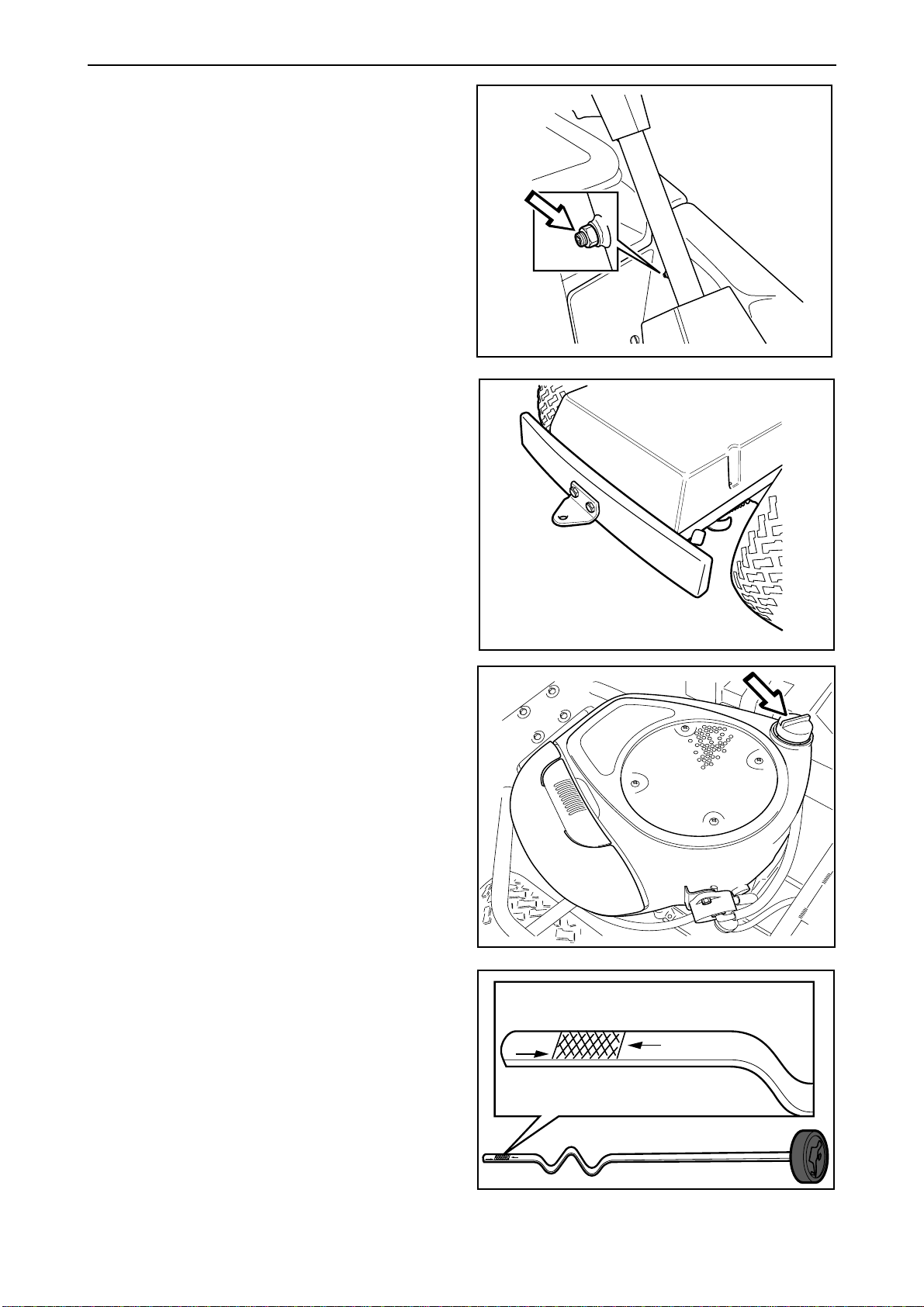
• Fit the steering wheel with the steering column
tube on the steering shaft.
• Screw in the socket head cap screw so that it
goes in the slot on the steering shaft. Work on
the steering wheel and tighten the socket head
cap screw so that it bottoms in the slot.
• Fit the lock nut on the socket head cap screw.
Tow plate
The tow plate is fitted the “wrong way round” at the
factory for transport reasons. Fit the tow plate on
the rear bumper as shown in the diagram.
Check the oil level in the engine
Check the oil level in the engine when the Rider
stands horizontal with the engine switched off.
Lift up the engine cover.
Loosen the dipstick and pull it out. Wipe the
dipstick and replace it.
The dipstick should be screwed fully down.
Loosen the dipstick and pull it out again. Check the
oil level.
The oil level should lie between the markings on
the dipstick. If the level is close to the “ADD” mark,
top up with oil to the “FULL” mark on the dipstick.
The oil is poured in the same hole the dipstick fits
in.
Fill the oil slowly. Tighten the dipstick correctly
before starting the engine. Start and run the engine
at idling speed for approx. 30 seconds. Turn off the
engine. Wait 30 seconds and check oil level. If
necessary fill so that the oil comes up to the
”FULL” mark on the dipstick.
Use engine oil SAE 30 or SAE 10W/30, class SFCC on all machines up to 2002 models as well as
later models of Rider 11 and 13 with side-valve
engines.
Rider 16, 2003 model
ADD
FULL
From 2003 Rider 16 models use first and foremost
synthetic engine oil class SJ-CF 5W/30 or 10W/30,
otherwise SAE30, class SF-CC.
The engine takes a total of 1.4 litres/1,5 USqt of oil.
12 – English
www.mymowerparts.com
ADD
FULL
Page 15

RIDER 850
For Husqvarna Parts Call 606-678-9623 or 606-561-4983
Delivery measures
Checking the oil level in the
transmission
(Not Rider 11)
Remove the transmission cover. Loosen both
screws (one on each side) and lift off the
transmission cover.
Check that there is oil in the transmission’s oil tank.
Fill if necessary with engine oil SAE 10W/30 (class
SF–CC).
IMPORTANT INFORMATION
Check and top up with oil after each test
drive. The oil level will drop if there are
air pockets in the transmission.
Wheels
Fit the wheels (certain markets). The tyre pressures
should be 60 kPa (0,6 kp/cm2 /8,5 PSI) on all the
wheels.
To improve the driving capacity the pressure in the
back tyres can be reduced to 40 kPa
(0,4 kp/cm2 /5,6 PSI).
Maximum permitted pressure is 100 kPa
(1,0 kp/cm2 /14 PSI).
IMPORTANT INFORMATION
Different pressures in the front tyres will
cause the blades to cut the grass at
different heights.
Checking and adjusting of the mowing
deck’s ground pressure and parallelism
Carried out after checking the tyre pressures. See
respective sections in this Workshop Manual.
www.mymowerparts.com
English – 13
Page 16

For Husqvarna Parts Call 606-678-9623 or 606-561-4983
Delivery measures
Test running
Fill up with petrol. The engine should be run on the
lowest 85 octane unleaded petrol (no oil admixture).
It can be beneficial to use environmentally adapted
alkylate petrol. Do not use petrol that contains
methanol.
WARNING!
Petrol is highly inflammable.
Observe caution and fill up with
petrol outdoors.
WARNING!
Never run the engine indoors, or
in enclosed or poorly ventilated
areas. Engine exhaust fumes
contain poisonous carbon monoxide.
Start the engine.
Check that the machine is in neutral and standing
on level ground when the parking brake is released.
(Not Rider 11)
Check the function of the parking brake.
Check driving forwards (1) and backwards (2).
Check that the starter does not function when any
of the hydrostatic transmission pedals are activated
(Rider 13, 16) or when the gear stick is not in
neutral (Rider 11).
Check that the engine stops when getting up from
the seat when any of the hydrostatic transmission
pedals are activated (Rider 13, 16) or when the
gear stick is not in neutral (Rider 11).
Check that the starter does not function when the
mowing unit is in its lower position.
2
1
14 – English
www.mymowerparts.com
Page 17

For Husqvarna Parts Call 606-678-9623 or 606-561-4983
Delivery measures
Check the function of the mowing deck and that
there is no abnormal noise.
The mowing height can be regulated in 9 different
positions with the lever.
Deck with rear ejector, 40-90 mm,
mowing height
(1 9/16" - 3 9/16")
BioClip- and Combi- deck, 45-95 mm,
mowing height
(1 3/4" - 3 3/4")
Speed regulator
Check that the engine’s maximum speed is
regulated at:
Rider 11 2 900 - 3 100 rpm
Rider 13 2 900 - 3 100 rpm
Rider 16 2 900 - 3 100 rpm
Rider 16 2003 - 2 800 - 3 000 rpm
Administration
Fill in the sales certificate and customer register
etc.
Do not forget to enter the manufacturing number on
page 3 of the operator’s manual and to verify the
delivery service in the service log.
www.mymowerparts.com
English – 15
Page 18

RIDER
850
RIDER
850
For Husqvarna Parts Call 606-678-9623 or 606-561-4983
Design and function
General
Husqvarna Riders is a series of ride-on mowers
with a large capacity. It is available in several sizes,
from the smallest Rider 11 to the largest Rider
ProFlex 21.
This manual deals with the slightly smaller
machines, the larger Pro-and ProFlex machines
can be found in a separate manual. All Riders have
articulated steering in order to easily cut around
trees and other obstacles. Moreover, they all have
front-mounted mowing decks for controlled cutting
R
R
IDER
IDER
850
850
0
0
5
5
8
8
R
R
E
E
ID
ID
R
R
and for best possible cutting results.
Husqvarna Riders can, moreover, be equipped
with various accessories such as moss rake and
dozer blade which make them flexible working
tools throughout the year.
Rider 11 and Rider 11 Bio can be delivered with a
manual gearbox, while the other models are only
available with hydrostatic transmission.
Rider 11 and Rider 13 have a mowing deck with
rear ejection. They can also be ordered with a Bio
deck, in which case they are called the Rider 11 Bio
or Rider 13 Bio.
Rider 16 is available with different mowing decks.
Bak 97 (rear ejection)
Sido 97 (side ejection)
BioClip 90
Combi 103 or Combi 112.
Earlier versions even BioClip 103 or BioClip 112
16 – English
www.mymowerparts.com
Page 19

For Husqvarna Parts Call 606-678-9623 or 606-561-4983
Design and function
Serial number
The serial number can be found on the printed
plate attached to the front, left-hand side under the
seat. Stated on the plate, from the top are:
• The machines type designation.
• The manufacturer’s type number.
• The machine’s serial number.
State the type designation and serial number when
ordering spare parts.
On older machines the engine’s manufacturing
number is punched on a plate that is riveted to the
fan cover. On newer engines in Rider 16 the data is
punched on the cover.
The plate states:
• Model.
• Type.
• Code.
Please state these when ordering spare parts.
The transmission’s serial number is stated on the
barcode decal located on the front of the housing
on the left-hand drive axle:
• The type designation is stated above the
barcode and starts with the letter “K”.
• The serial number is stated above the barcode
and has the prefix “s/n”.
Older engines all versions
Newer engines Rider 16 (2003-)
• The manufacturer’s type number is stated under
the barcode and has the prefix “p/n”.
State the type designation and serial number when
ordering spare parts.
www.mymowerparts.com
English – 17
Page 20

For Husqvarna Parts Call 606-678-9623 or 606-561-4983
Design and function
Engine
These Husqvarna Riders have single-cylinder, aircooled engines from Briggs & Stratton.
More intricate engine repairs are not described in
this workshop handbook, these can instead be
read in Briggs & Stratton's own handbooks which
contain detailed information about adjusting and
repairing the engines. The handbooks can be
ordered from an authorized service workshop.
The order numbers for the respective Rider models
are found in the table below. Please state these
when ordering manuals:
Model B & S model no.
Rider 11 28B707
Rider 13 286707
Rider 16 -2002 28N707
Rider 16 2003- 282H070110
Rider 11 and Rider 13 are fitted with a single
cylinder side-valve engine of 10.5 resp. 12.5 hp
with splash lubrication. Rider 16 is fitted with a
single cylinder overhead-valve engine of 15.5 hp. A
new overhead-valve engine with AVS (Anti Vibration System) has been introduced from 2003
models.
Side-valve engine Rider 11 and 13
It is important that only original spare parts are
used when repairing the engines. If other parts are
used, the guarantee shall no longer be valid.
Overhead-valve engine Rider 16 (2003-)
18 – English
www.mymowerparts.com
Page 21
For Husqvarna Parts Call 606-678-9623 or 606-561-4983
Design and function
Steering
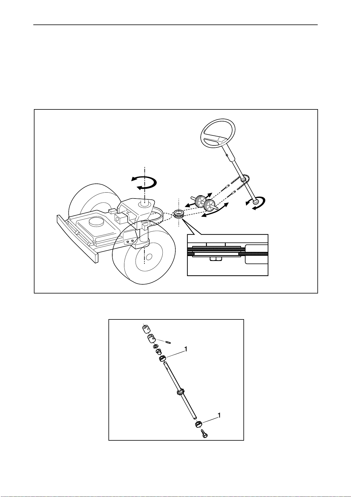
All the ride-on mowers in the Rider series have
articulated steering. The steering force from the
steering wheel is transferred to the rear section via
wires and a chain. This ensures that the ride-on
mower is easy to manoeuvre, as well as having
high-precision steering. A Rider easily cuts around
all obstacles that may be found on the lawn.
Thanks to the articulated steering, the turning
radius is extremely small, the uncut circle when the
steering wheel is fully turned is just 20-30 cm
(8"-12")depending on which model is chosen.
Outline diagram of the articulated steering function.
Rider machines have a sliding bearing (1) on the
steering column.
www.mymowerparts.com
English – 19
Page 22

For Husqvarna Parts Call 606-678-9623 or 606-561-4983
Design and function
Driving
Rider 11 has a manual gear box with five forward
gears, neutral and one reverse gear. This gear box
is an "inline" type, which means that you can
change from neutral to fifth gear without having to
go through all the other gears.
Manual gear box on Rider 11 and Rider 11 Bio.
Rider 13 and Rider 16 are equipped with
hydrostatic transmission which provides the driver
complete control. Continuously variable speed
control, forwards and reverse, is by means of a
pedal.
Hydrostatic transmission on Rider 13 and Rider 16.
Mowing deck
The entire Rider series is equipped with frontmounted mowing decks to ensure effective cutting
even in confined areas.
Rider 11 and Rider 13 have a mowing deck with
rear ejection and a cutting width of 850 mm (34").
Rider 11 Bio and Rider 13 Bio have a Bio deck with
a cutting width of 900 mm (36").
20 – English
www.mymowerparts.com
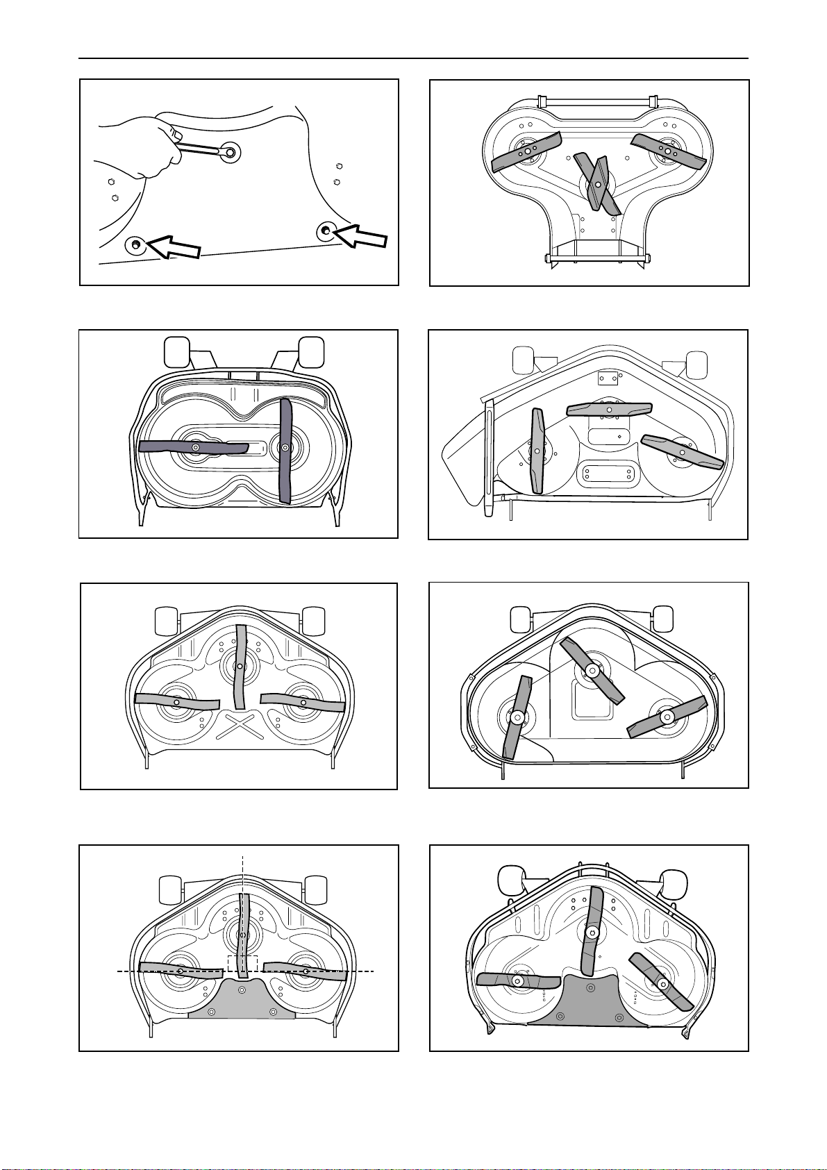
Rider 16 can be fitted with mowing decks with
either side or rear ejection where both have mowing
widths of 970 mm (38"), BioClip unit with mowing
width 900 mm (36") alternatively 1030 mm (41") or
Combi unit 1030 mm (41") alternatively 1120 mm
(44").
The Combi unit works as a BioClip unit when a
BioClip plug is fitted, but can be modified for rear
ejection by removing the BioClip plug.
Page 23
For Husqvarna Parts Call 606-678-9623 or 606-561-4983
Design and function
Removing the BioClip plug
BioClip 900 mm (36")
Mowing deck with rear ejection, 850 mm (34").
Mowing deck with side ejection, 970 mm (38").
BioClip 1030 mm (41")
90°
Combi 1030 mm (41").
Mowing deck with rear ejection, 970 mm (38").
90°
Combi 1120 mm (44").
English – 21
www.mymowerparts.com
Page 24
For Husqvarna Parts Call 606-678-9623 or 606-561-4983
Design and function
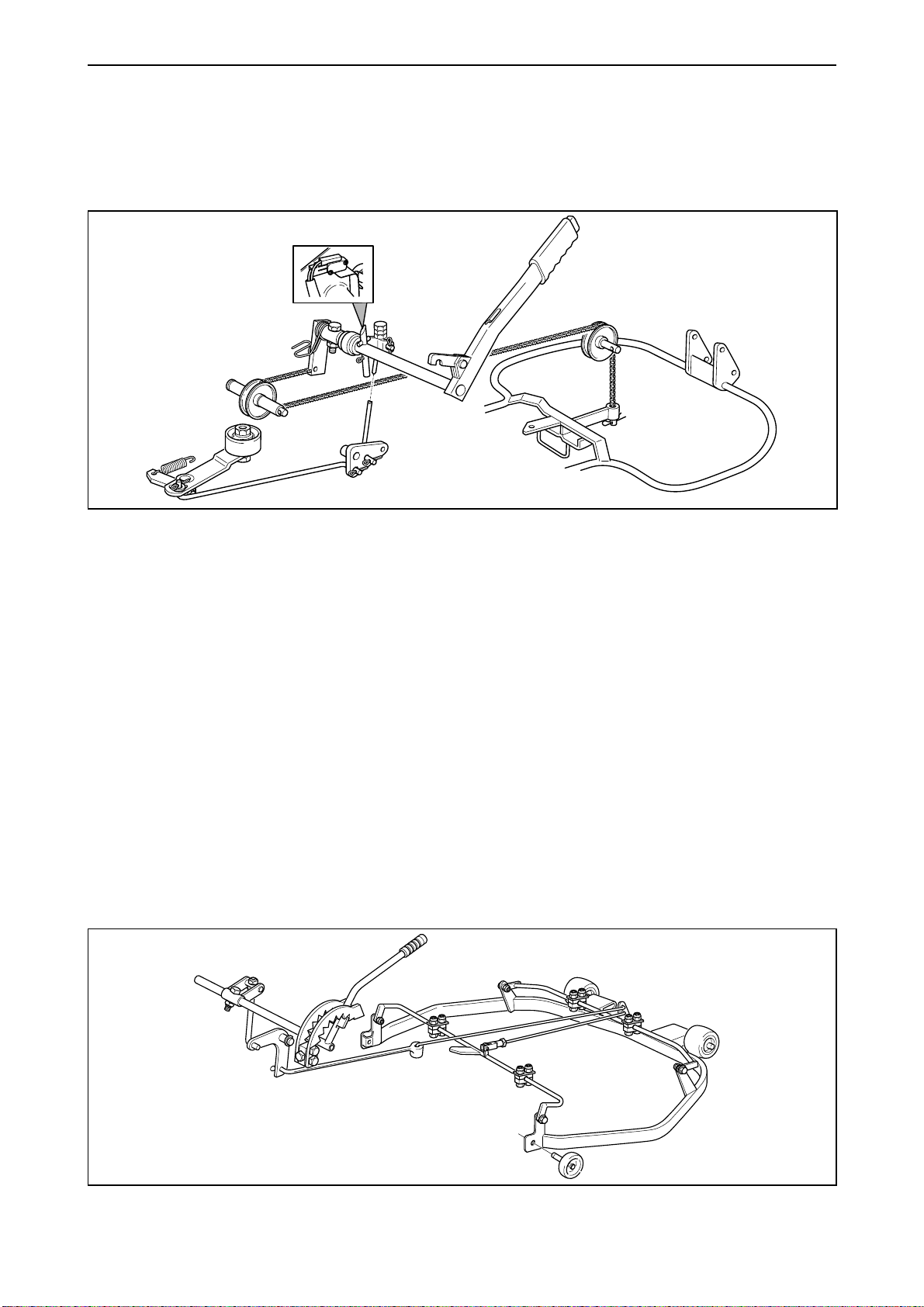
The mowing deck is raised and lowered using the
mechanical lifting lever, which actuates a shaft that
rotates.
When the shaft rotates, the chain that is secured in
an arm on the inner end of the shaft raises or
lowers the tool frame.
The attachment’s lifting device
When lowering the unit, the two connecting rods,
via the three-point link, will alter the belt adjuster so
that the drive belt is tensioned and the blades begin
to rotate.
When the attachment is raised the microswitch in
the safety circuit is actuated.
The mowing deck is rear suspended with the lug on
the rear transverse axle in a U-bracket on the tool
frame. The front of the tool frame is linked to a
bracket on the attachment. The front rollers are
supported against the ground, for example, when
turning when the attachment tends to lean. The
rollers on the rear section of the protective frame
are used when removing and fitting the mowing
deck or moving it to the service position.
Otherwise, when dismantling, the rear of the
attachment would fall directly to the ground when
the lug on the rear axle releases its grip.
The mowing height is adjusted using the lever,
which has a catch for the different mowing height
positions. The setting for the mowing height range
is located on the same axle, see ”Adjustment of the
mowing height range”. Two connecting rods via a
toggle joint actuate the protective frame around the
mowing deck and raise or lower the mowing deck’s
cover within the mowing height range.
There are two struts on the top of the cutting unit
cover. The upper one is coupled between the
horizontal connecting rod and the tongue of the
forward perpendicular shaft on the top of the
mowing deck cover. When the shaft is rotated, it will
raise or lower the cutting unit cover in relation to the
protective frame. The lower strut (parallel strut) is
connected between the front and rear transverse
axles, so that even the rear axle rotates in the same
way as the front axle. There is an adjuster on the
parallel strut to adjust the mowing deck cover’s
parallelism with the ground. See ”Checking and
adjusting the mowing deck’s the parallelism”.
Mowing height manoeuvring
22 – English
www.mymowerparts.com
Page 25
For Husqvarna Parts Call 606-678-9623 or 606-561-4983
Reparation instructions
Removing engine
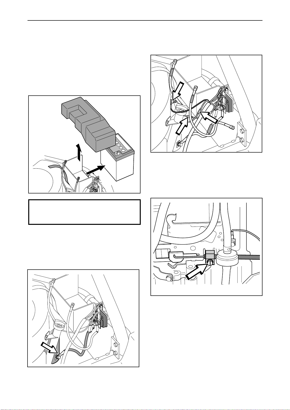
The figures under ”Dismantling” show Rider 11, 13
and Rider 16 in older designs (R16 up to the 2002
model), for a more recent Rider 16 design (2003-)
see ”Assembling the engine”. The text applies to all
versions.
1
3
Mark up and remove the engine's electrical
connections.
Newer engines, pull the connector apart.
IMPORTANT INFORMATION
Hold the bolts so that the poles are not
put under strain.
Remove the battery's fixing belt. Remove the safety
guard and remove the cable connections. Then, lift
out the battery.
2
4
Remove the clamp holding the throttle and choke
wire. Unhook the wire at its at its attachment.
Remove the cable which leads from the starter
relay to the start motor.
www.mymowerparts.com
English – 23
Page 26
For Husqvarna Parts Call 606-678-9623 or 606-561-4983
Reparation instructions
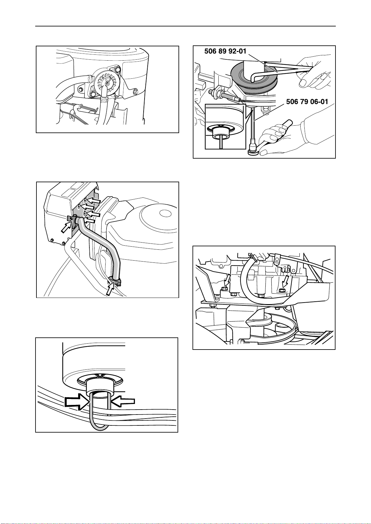
5
Remove the fuel line hose clamp from the fuel
pump and pull the fuel line downwards.
Tie the hose higher than the fuel tank level.
6
8
Insert tool no. 506 79 06-01 into the centre of the
engine pulley. Unscrew and remove the socket
head cap screw which holds the pulley and the
engine axle together. Use tool no. 506 89 92-01 as
a holder-on. Remove the pulley from the engine
axle.
Release the exhaust pipe clamps, and then remove
the exhaust pipe.
7
9
Remove the engine attachments, two on each side
of the engine, and remove the engine from the
mower.
Watch where the battery’s negative cable is
connected. Disconnect it from the engine if
necessary.
Lift the engine out of the mower, take care of the
key and spacer tube, located on the engine shaft.
Clamp together the wire holder under the engine
pulley with a pair of flat pliers and pull the wire
holder downwards.
24 – English
www.mymowerparts.com
Page 27
For Husqvarna Parts Call 606-678-9623 or 606-561-4983
Reparation instructions
Replacing engine
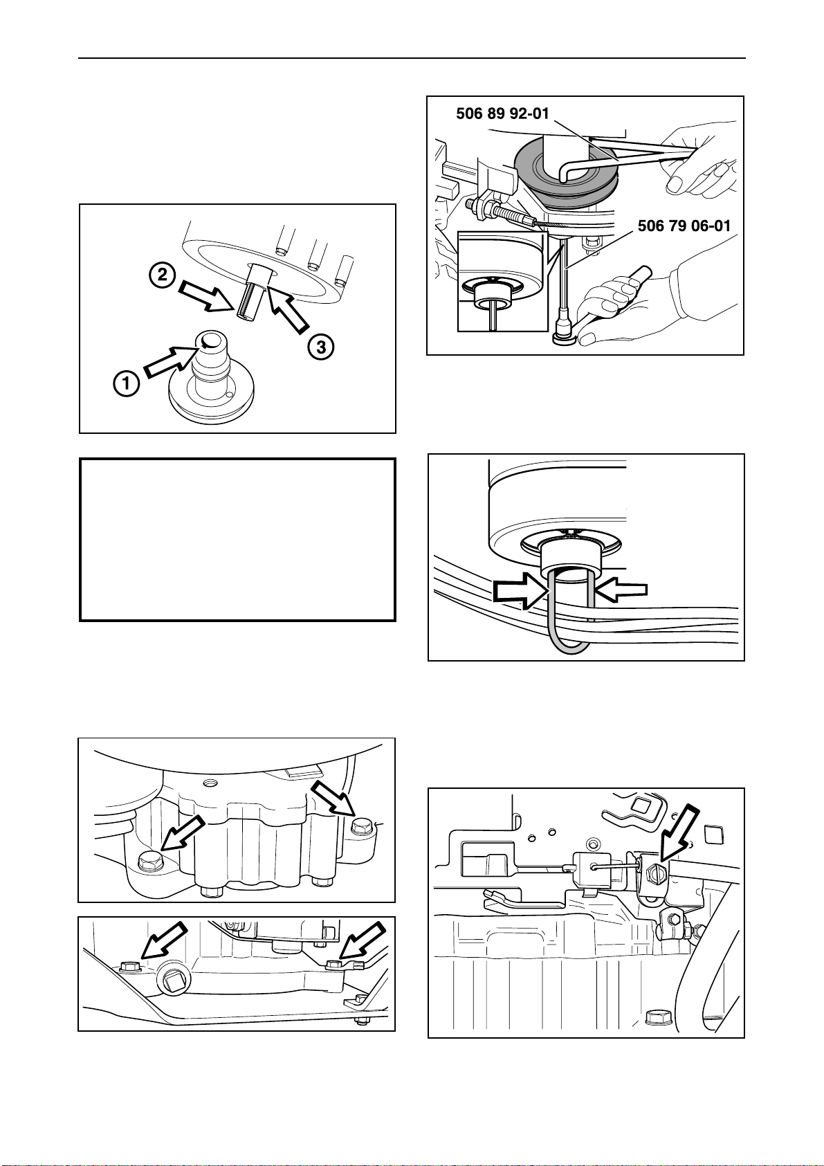
The figures under ”Assembling” show the newer
Rider 16 model (2003-). For
older designs (R16 up to the 2002 model), and
Rider 11 and 13 see ”Dismantling
the engine”. The text applies to all versions.
IMPORTANT INFORMATION
2
Position the pulley with tool no. 506 79 06-01 and
tighten it with moment (70-80 Nm/50-56 lbft). Use
tool no. 506 89 92-01 as a holder-on.
3
When installing the engine, it is important
that the pulley groove (1) is in a position
so the outgoing axle key (2) fits into the
groove (see diagram). Also check that
both spacing collars (3) and the key (2)
are firmly attached on the engine axle.
Grease the engine axle.
1
Position the wires in the wire holder, clamp the
holder together and, from below, lead it up through
the centre of the belt tensioner until it hooks over
the tensioner's upper edge.
4
Lower the engine and tighten the engine
attachments (two on each side of the engine) with
moment (20-25 Nm/14-18 lbft).
www.mymowerparts.com
Hook on the throttle wire at the carburettor and fit
the wire clamp without tightening it.
English – 25
Page 28
For Husqvarna Parts Call 606-678-9623 or 606-561-4983
Reparation instructions
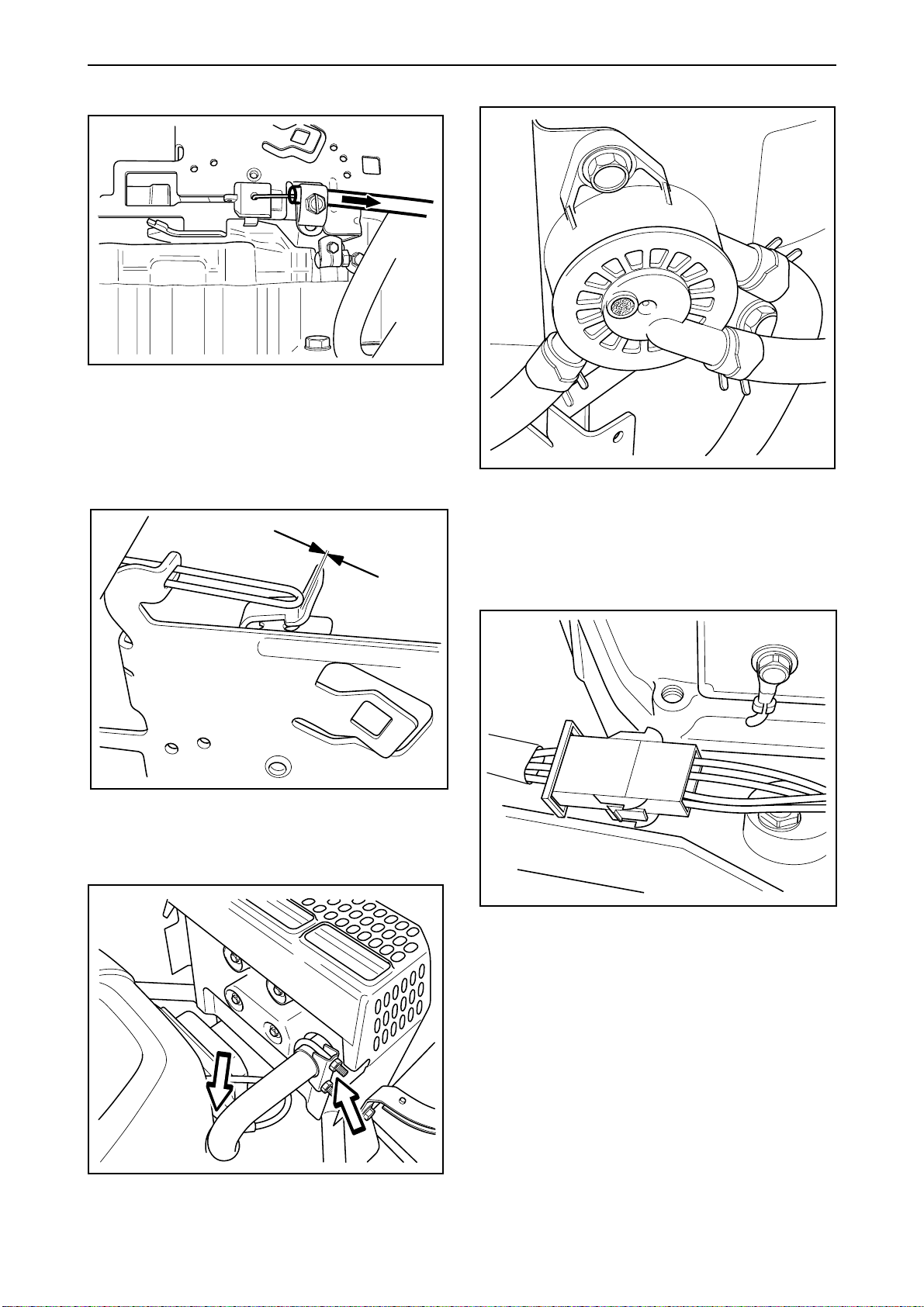
5
Push the throttle control to full choke position. Pull
the wire’s outer casing as far to the right as
possible and tighten the clamping screw. Pull back
the throttle control to the full throttle position and
check that the choke is no longer actuated.
7
Press the fuel line securely on the fuel pump and fit
the hose clamp.
Choke not actuated.
6
8
Attach the engine's electrical connections.
Fit the exhaust pipe and tighten the retaining
screws and clamps.
26 – English
www.mymowerparts.com
Page 29
For Husqvarna Parts Call 606-678-9623 or 606-561-4983
Reparation instructions
9
Tightly screw the cable from the start motor to the
starter relay.
10
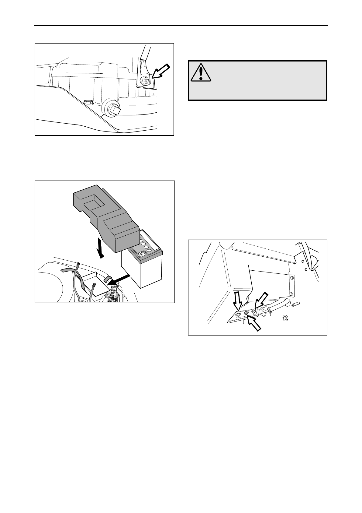
Fuel tank
Removal
WARNING!
Petrol is highly flammable and
environmentally hazardous.
Exercise caution to avoid fire and
spillage.
1. Place an appropriate container to catch the
petrol. The tank holds approx. 7 litres / 7.4
USqt.
2. Empty the petrol tank by removing the hose
from the connector under the tank.
If you do not wish to empty the tank, you can
pinch the hose with lockable welding pliers and
then remove the hose and hose clamp from the
fuel filter’s lower connector. You must then be
sure to keep the hose opening higher than the
fuel level in the tank.
3. Remove the three screws that fix the tank to the
bracket. Lower the tank and pull out the hose
through the frame of the machine (if it has been
loosened by the fuel filter).
Lift the battery into place and fasten the cable
connections and safety guard. Tighten the catching
belt.
Fitting
1. It is easier to work if you empty the tank before
fitting. Pull the tube into place, pull it under the
corner of the crank house, and attach it to the
fuel filter with the hose clamp. Make sure that
the hose cannot be chafed or rubbed.
2. Position the tank in the bracket, and secure with
the bolts.
3. Fit the fuel hose and the hose clamp to the
connector under the tank as required. Fill with
petrol and check that there are no leaks.
www.mymowerparts.com
English – 27
Page 30
For Husqvarna Parts Call 606-678-9623 or 606-561-4983
Reparation instructions
Changing the oil
The engine oil should be replaced after the first five
hours of running time, see service chart. Thereafter
it should be replaced every 50 hours of running
time (25 hours in harsh operating conditions).
WARNING!
Engine oil can be very hot if it is
drained off directly after the
engine is stopped. Therefore
allow the engine to cool down
first.
IMPORTANT INFORMATION
Spent engine oil is hazardous to health
and must not be poured out on the ground or in the nature, but should be
handed in to a designated place for
recycling.
Avoid skin contact and wash any spillage
with soap and water.
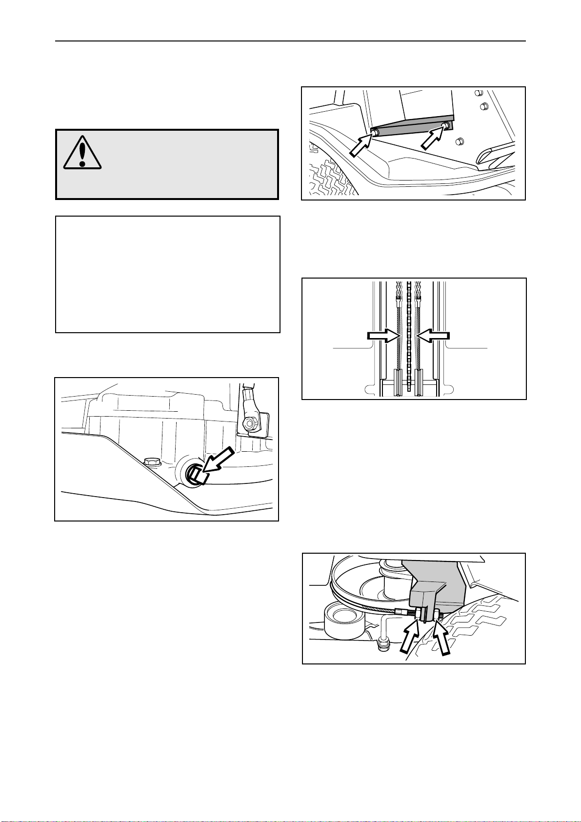
Checking and adjusting steering wires
1
Remove the frame plate by releasing the screws
(two on either side).
2
Drain plug on Rider 16
Tip! When draining the engine oil use a folded
piece of cardboard to funnel the oil into the container.
Place a container under the drain plug on the left
side of the engine.
Remove the dipstick and drain plug. Let the oil
drain into the container.
Refit the drain plug and tighten it.
Fill with oil up to the “FULL” mark on the dipstick.
Pour the oil into the same hole the dipstick goes in.
Filling procedure, see ”Delivery measures\Checking
the engine’s oil level”. Use engine oil as set out in
the ”Specifications” chapter.
Run the engine until warm, then check that there
are no oil leaks from the drain plug.
Ensure that the cables are properly situated under
the steering cable pulleys in the frame tunnel.
The tension is checked by squeezing together the
wires (as shown in the diagram). Without having to
apply too much force, the wires should be able to
be squeezed to half the distance between them.
Change the cable if it has a damaged strand
causing loose threads to protrude.
3
Hold the wire so it does not twist.
Stretch the wires by tightening the adjuster nuts
(one wire on each side of the ride-on mower). Do
not overtension them, they should only be tightened up to the steering rim. Stretch both wires
equally so that the steering wheel position is not
changed.
Check the wire tension as set out in point 2 after
you have made the adjustment.
28 – English
www.mymowerparts.com
Page 31
For Husqvarna Parts Call 606-678-9623 or 606-561-4983
Reparation instructions
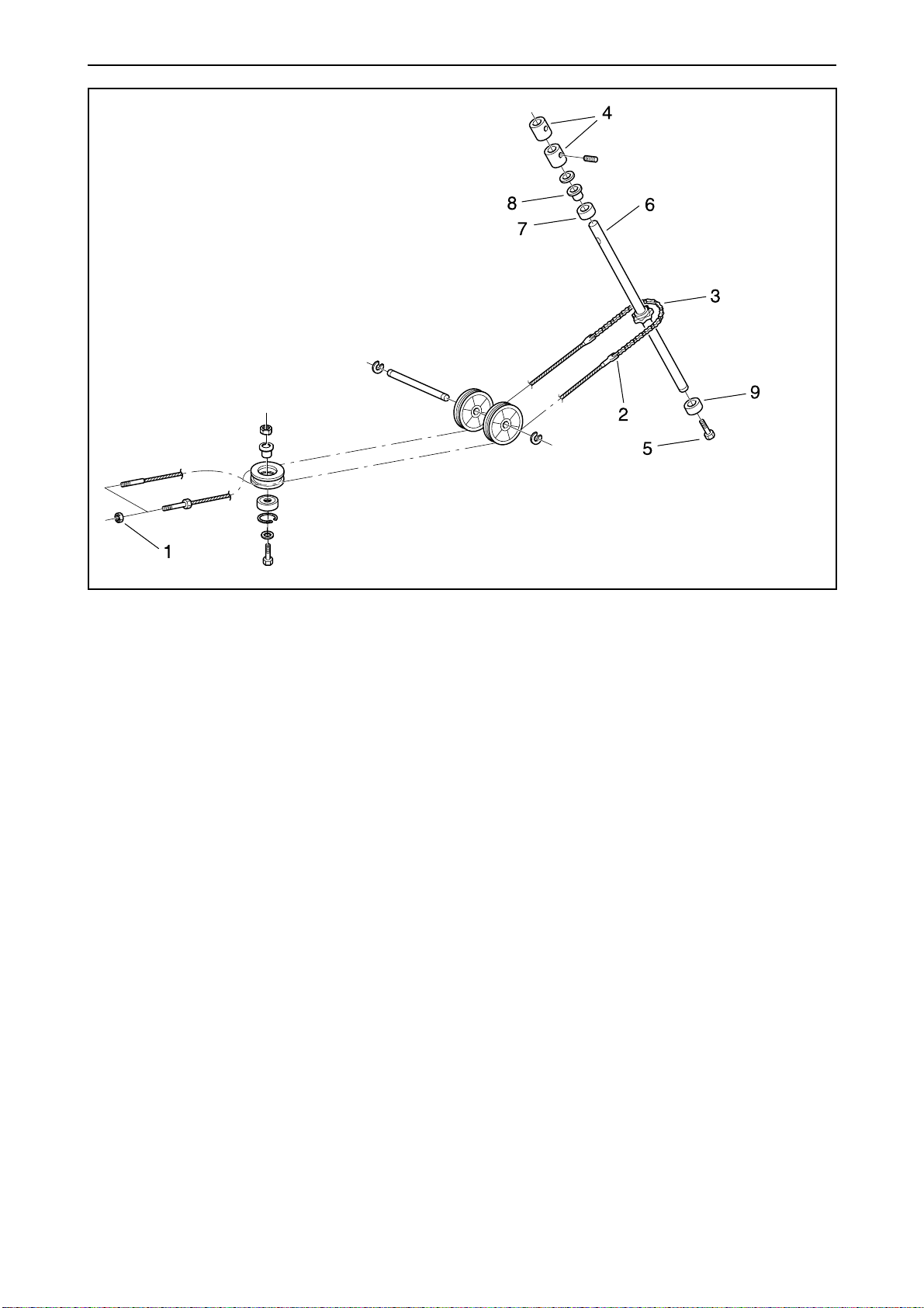
Replacing steering wires
1. Release the steering wires' rear attachment (1).
2. Remove the frame plate.
3. Release the steering wires' front attachment (2)
at the steering transmission chain (6) and pull
the steering wires out throught the frame.
Note. If the old wires are still complete, the new
wires can be attached to the old ones when
they are pulled out through the frame, the new
wires will then come automatically into place.
4. Ensure that the steering wheel is in the centre
position when the rear wheels are centred. Reset the chain on the steering column’s sprocket
or adjust the rear fixture (1) for the steering
cables as needed.
Hold the cables with, for example, a wrench
when mounting so that they do not twist.
Attach the new wires. Once the new wires are
in place, check the wire tension (see “Checking
and adjusting steering wires”).
Removal/installation of steering axle
1. Release the steering wires' rear attachment (1).
Remove the frame plate.
2. Remove the steering wheel and steering
column by releasing the lock nut and
unscrewing the locking screw, lift the steering
wheel and steering column upwards.
3. Remove the two steering wheel rod carriers (4).
4. Unscrew the bolt (5) from the bottom end of the
steering column.
5. Pull the steering axle (6) upwards and move the
lower part of the axle backwards to remove the
steering transmission chain (3).
6. Move the upper bearing (7) uppwards until it
goes free from the steering axle (6). If the
bearing is to be replaced, the bushing (8) must
be knocked out of the bearing.
7. Slide the bearing (9) off the bottom end.
8. Take the steering axle out (6) downwards.
9. To assemble the steering axle, the reverse
order is applied. For assembly purposes, the
two steering wheel rod carriers (4), are tightened with moment (5–10 Nm/3,5-7 lbft).
www.mymowerparts.com
English – 29
Page 32
For Husqvarna Parts Call 606-678-9623 or 606-561-4983
Reparation instructions
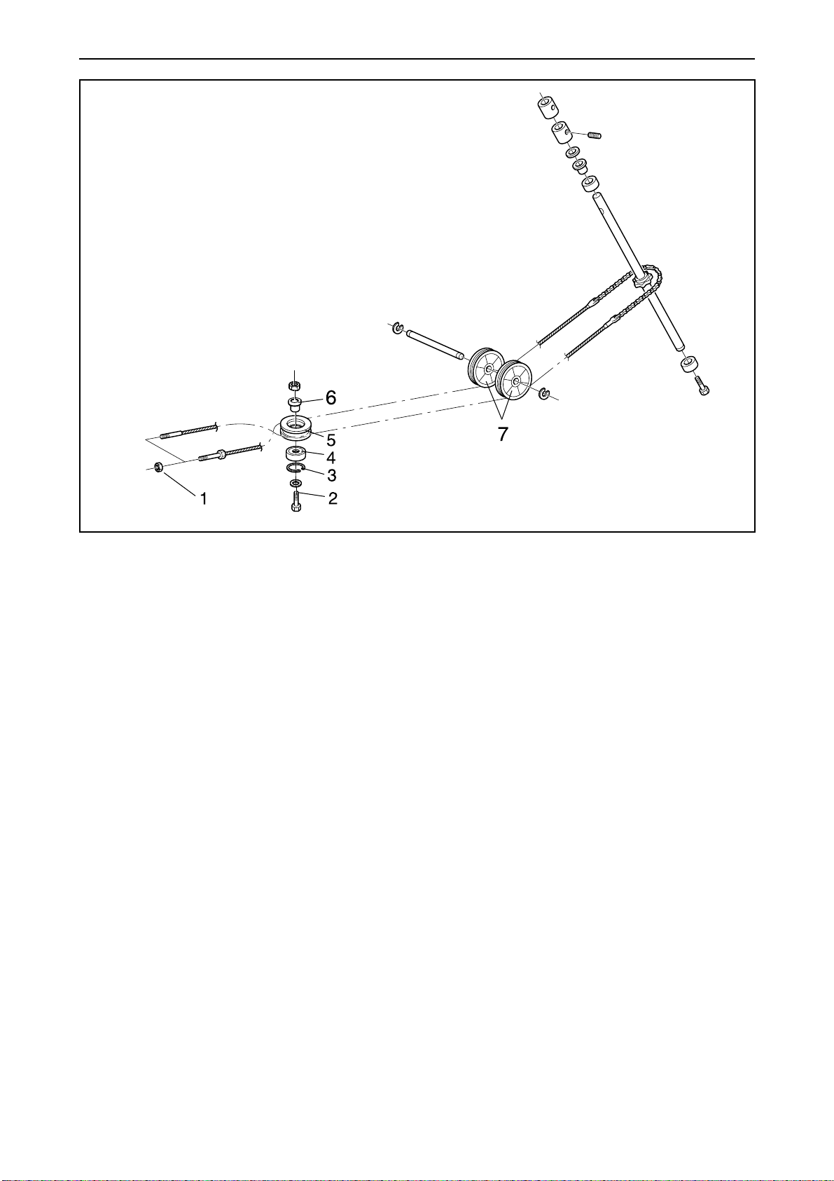
Removal/installation of wire wheel
1. Remove the frame plate.
2. Detach the steering wires' rear attachment (1) .
3. Remove the screw (2) and detach the wire
wheel (5).
4. Remove the bearing's circlip (3) and knock out
the bearing (4).
5. To install the wire wheel, the reverse order is
applied.
The screw (2) is to be mounted in the rear hole
on the frame. The bushing (6) is to be placed
between the frame and the cable pulley.
Ensure that the cables are properly situated
under the steering cable rollers (7) in the frame
tunnel.
Ensure that the steering wheel is in the centre
position when the rear wheels are centred. Reset the chain on the steering column’s sprocket
or adjust the rear fixture (1) for the steering
cables as needed.
Hold the cables with, for example, a wrench
when mounting so that they do not twist.
After installation, check the wire tension (see
“Checking and adjusting steering wires”).
30 – English
www.mymowerparts.com
Page 33
For Husqvarna Parts Call 606-678-9623 or 606-561-4983
Reparation instructions
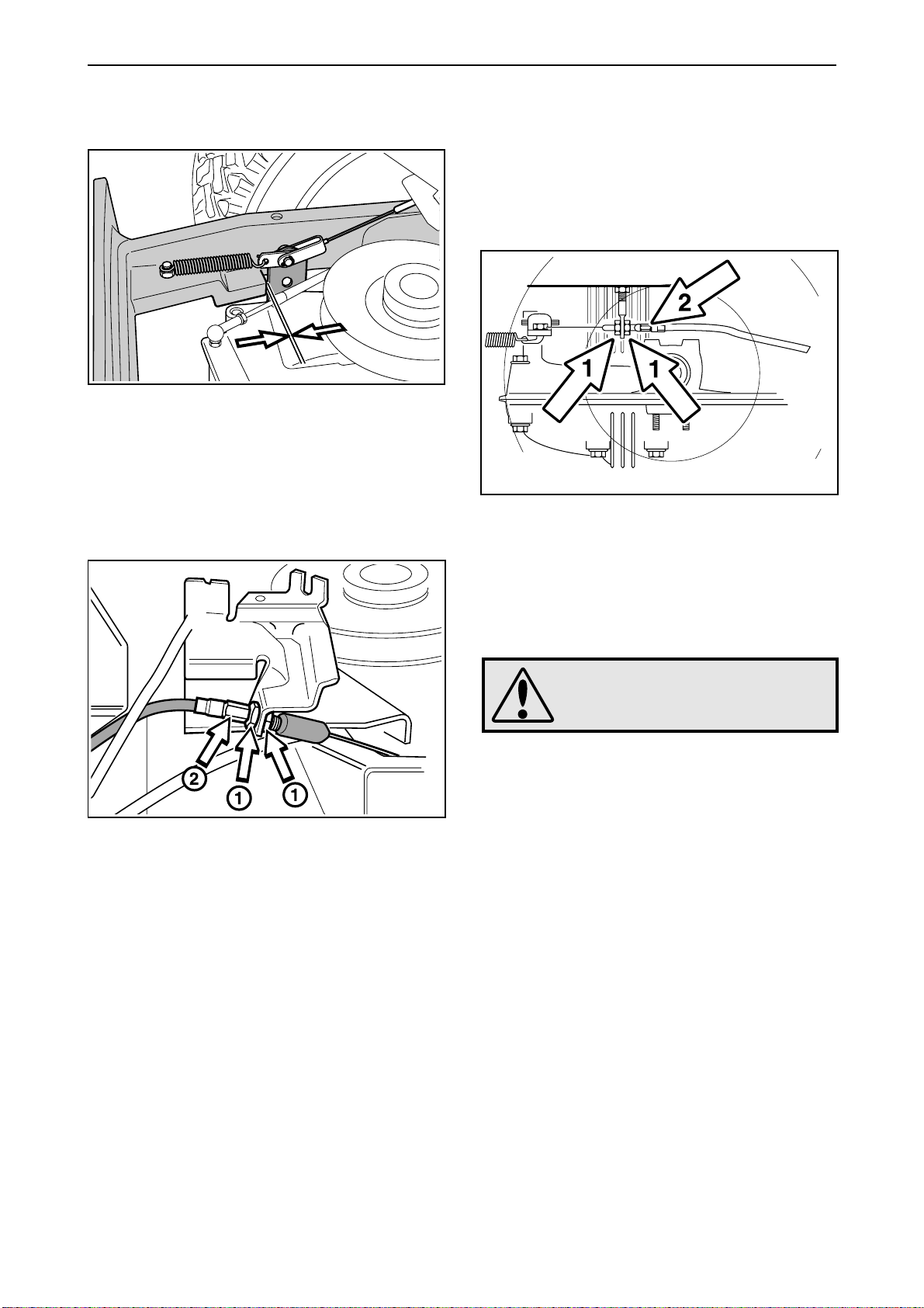
Checking and adjusting brake wire
Rider 11
Check that the brake is correctly adjusted by
measuring the distance between the brake lever
and the front edge of the recess on the chassis.
The distance should be 0–1 mm/0-0,040" when the
brake is not applied.
Rider 13 and Rider 16
Check that the brake is correctly adjusted by
positioning the ride-on mower on a gentle slope and
applying the brake.
If the ride-on mower does not stand still, the brake
needs to be adjusted.
The brake is adjusted in the following way:
1. Release the lock nuts (1).
1. Remove the lock nuts (1).
2. Stretch the wire with the adjuster screw (2) so
that the distance between the brake lever and
the front edge of the recess on the chassis is 1
mm/0,040".
3. Tighten the lock nuts (1) after adjustment.
When the brake wire has been adjusted, check
that the brake lever does not have too much
movement. If the lever's free movement
exceeds 9 mm/3/8", this should be adjusted by
tightening the nut on the brake lever.
2. Stretch the wire with the adjuster screw (2) until
all the play in the wire disappears.
3. Tighten the lock nuts (1) and finally check that
the brake is correctly adjusted.
WARNING!
A badly adjusted brake can lead
to reduced braking capacity.
www.mymowerparts.com
English – 31
Page 34
For Husqvarna Parts Call 606-678-9623 or 606-561-4983
Reparation instructions
Checking and adjusting gear control
Rider 11
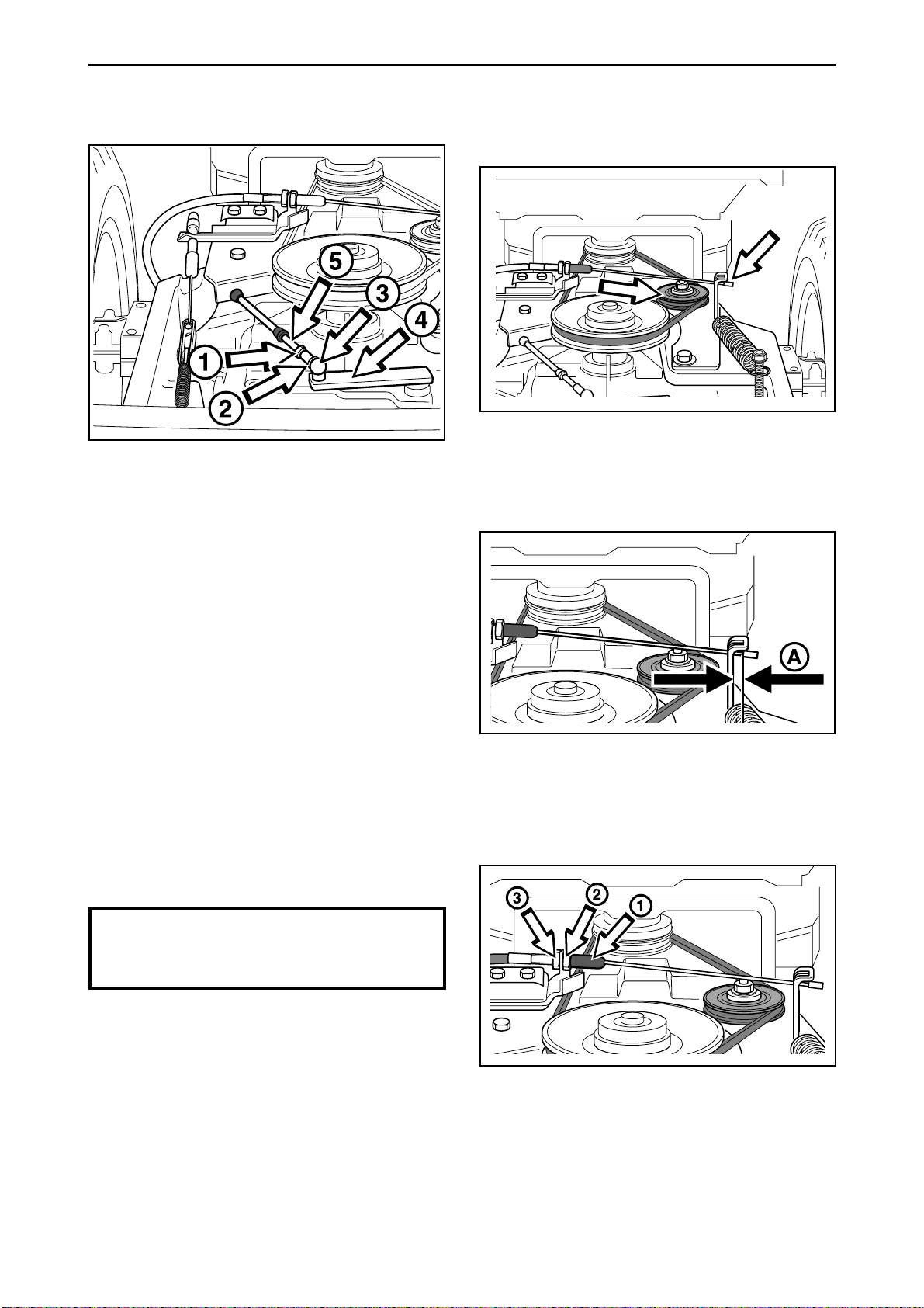
Check the gear control adjustment by setting the
gear change lever to the ”N” position. When the
lever (4) goes easily into the neutral position, the
control is correctly adjusted.
In other cases, the control is adjusted in the
following way:
Checking and adjusting freewheel
clutch Rider 11
1
The freewheel clutch is correctly adjusted when the
tensioning wheel's outward movement is stopped
by the belt and not by the wire.
2
1
Detach the lock nut (1) on the ball joint.
2
Press the locking spring (2) backwards so that the
spherical socket (3) can be lifted away from the pivot
on the lever (4).
3
Adjust the spherical socket (3) position on the
connecting rod (5) until the right adjustment is
obtained.
4
Lock the setting with the lock nut (1) and press the
locking spring (2) into position.
IMPORTANT INFORMATION
Check that the locking spring goes
through the hole in the spherical socket.
There should be a play (A) of 8-10 mm/5/16" - 3/8"
between the wire nipple and the lever.
3
32 – English
Adjust the freewheel clutch wire as follows:
• Pull out the rubber sleeve (1). Loosen the nut (2)
and adjust the wire using the adjuster screw (3).
• Tighten the lock nut (2) after adjustment.
www.mymowerparts.com
Page 35
For Husqvarna Parts Call 606-678-9623 or 606-561-4983
Reparation instructions
Checking and adjusting throttle control
Rider 13 and Rider 16
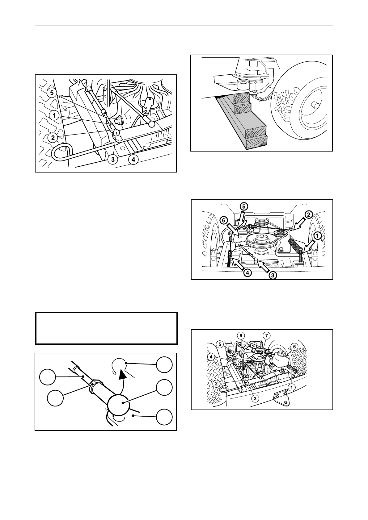
1. Detach the locking nut (1) on the ball joint.
2. Push the lock spring (2) forwards far enough
for the spherical socket (3) to be lifted off from
the pivot on the lever (4).
Replacing articulated steering bearing
1
• Remove the engine according to the earlier
description (see “Removing engine”).
• Block up the ride-on mower in front of the
articulated steering.
2 Rider 11
3. Press the throttle pedal to the bottom and
move the lever (4) forwards as far as it goes
using a screwdriver.
4. Adjust the position of the spherical socket (3)
on the connecting rod (5) so that it just fits over
the pivot on the lever. Fit the spherical socket
on the pivot.
5. Lock the setting with the lock nut (1) and press
the locking spring (2) into position.
IMPORTANT INFORMATION
Check that the locking spring goes
through the hole in the spherical socket.
2
5
3
1
• Release the tensioning wheel spring (1).
• Release the clutch, gear and brake wire (2, 3
and 4) and remove the wires' holder plates (5
and 6).
2 Rider 13 and Rider 16
4
• Release the tensioning wheel spring (1).
• Release the hydrostatic transmission wire (2)
from the arm (3) and the casing from the holder
(4).
• Release the cable from the neutral position
contact (5).
• Release the brake wire from the arm under the
tank and the casing’s holder from the rear frame
(6).
www.mymowerparts.com
English – 33
Page 36
For Husqvarna Parts Call 606-678-9623 or 606-561-4983
Reparation instructions
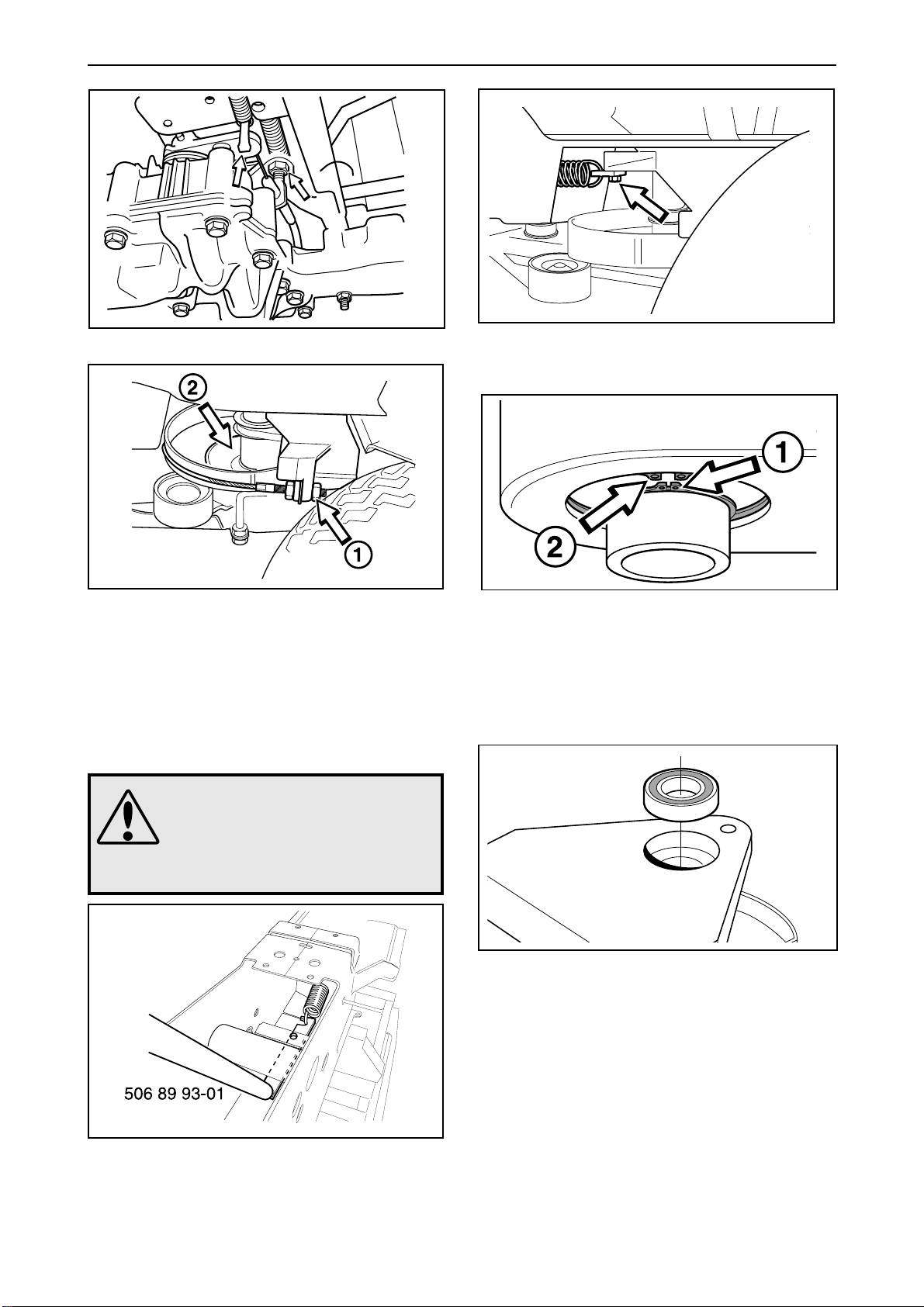
3
5
• Work off the belts from the pulley (2).
• Loosen the steering wires (1) and remove the
steering rim.
• Remove the pulley (2). Move the lower part
forwards, the upper part backwards and detach
the pulley.
4
WARNING!
The articulation spring is
strongly tensioned and can
cause injury if it flies off. Wear
safety glasses and gloves when
removing/attaching the spring.
Remove the inner circlip (1) from the lower bearing
(see diagram). The rear section is now loose and
can be moved. Then detach the outer circlip (2) and
take the bearing out downwards.
6
• Take the upper bearing out upwards, if it does
not come out easily, it should be knocked out
from below.
• Insert the new bearings and assemble the
articulated steering in the reverse removal order.
Detach the articulation spring. This spring is
heavily tensioned and should be offloaded using
tool 506 89 93-01 before the bolt for the rear
bracket is removed.
34 – English
www.mymowerparts.com
• After re-assembly, the wire tension should be
checked (see “Checking and adjusting steering
wires”). Also check that the controls and wires
are correctly adjusted.
• Check the setting of the neutral position switch
on machines with hydrostatic transmission, see
”Electrical system\Microswitch neutral position”.
Page 37
For Husqvarna Parts Call 606-678-9623 or 606-561-4983
Reparation instructions
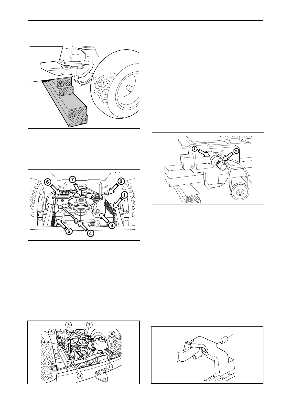
Removal of swing axle
1
• Block-up the machine in front of the rear frame.
• Remove the transmission/gear box cover.
2 Rider 11
• Release the tensioning wheel spring (1).
• Release the hydrostatic transmission wire (2)
from the arm (3) and the casing from the holder
(4).
• Release the cable from the neutral position
contact (5).
• Release the brake wire from the arm under the
tank and the casing’s holder from the rear frame
(6).
• Remove the circlip and lift off the hydrostatic
transmission’s fan (7).
• Remove the rear belt (8).
• Remove the circlip and washer from the swing
axle and pull the rear frame backwards.
3
• Detach the tensioning wheel spring (1) and the
clutch wire (2).
• Disconnect the tensioning wheel arm (3) from
the rear frame, and detach the belt from the gear
box pulley.
• Detach the gear and brake wires (4 and 5) and
remove the wires' holding plates (6).
• Remove the circlip and washer from the swing
axlel (7) and pull the rear frame out backwards.
2 Rider 13 and 16
Remove the circlip and washer from the swing
axle's inner holder (1) and pull the swing axle out
backwards. Use a sledgehammer or puller if
needed.
If the dust protection (2) is damaged, this should be
replaced by a new one.
Replacing bushings
Once the swing axle has been removed the
bushings fitted to the rear frame must be replaced.
Dismantling is carried out using a standard drift,
see ”Special tools”.
Assembling new bushings is carried out using a
drift, see ”Special tools”. Ensure the grooves in the
bushings run horizontally. It is important that the
outer edge of the outermost bushing is flush with
the outer edge of the hole.
Lubricate the bushings with a lithium-based grease.
www.mymowerparts.com
English – 35
Page 38
For Husqvarna Parts Call 606-678-9623 or 606-561-4983
Reparation instructions
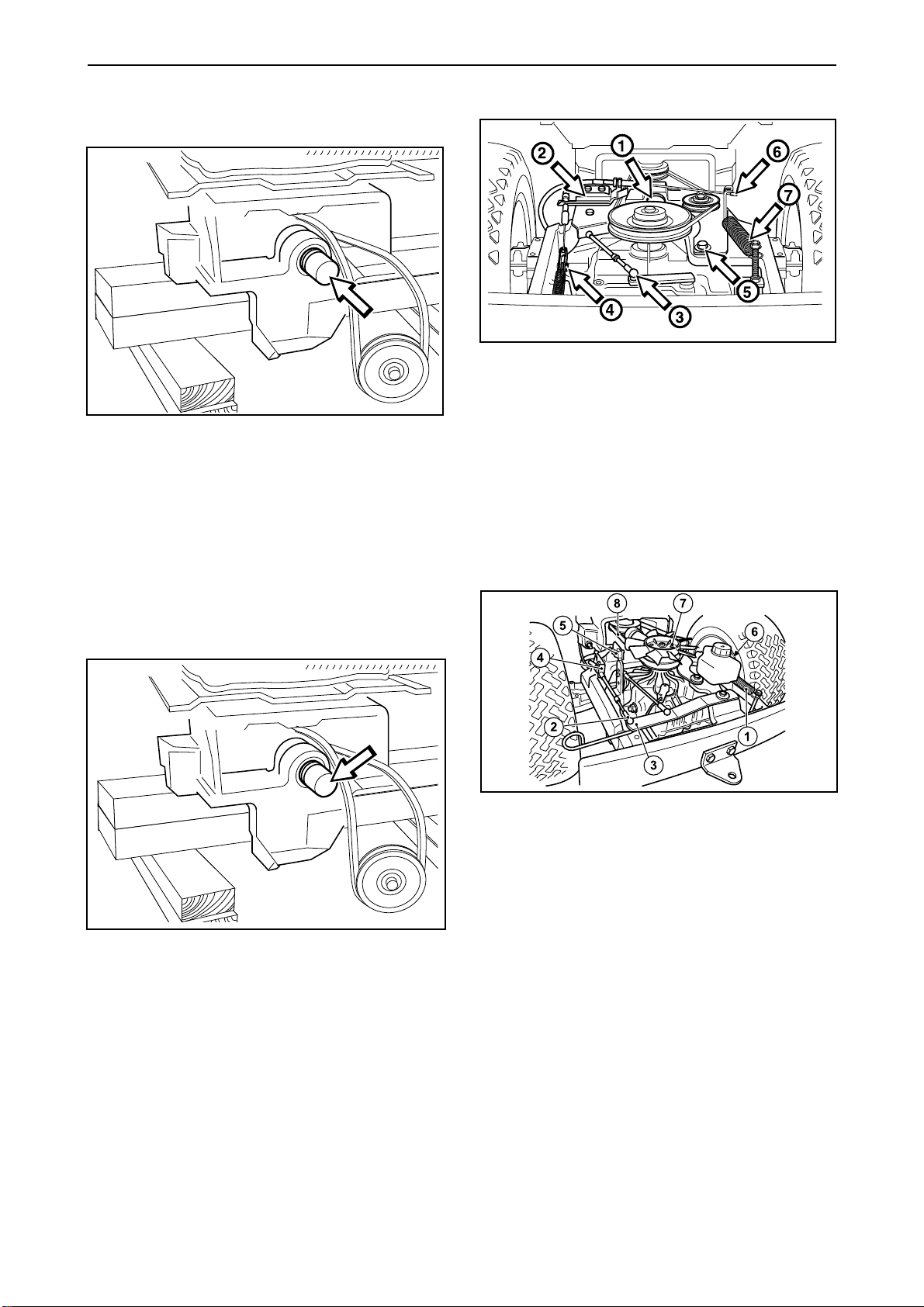
Installation of swing axle
1
• Grease half of the axle (the half that has not
been turned down) and press it from the back
into the steering spindle (see diagram).
• Attach the washer and circlip on the swing axle's
inner holder.
3 Rider 11
• Attach a washer and circlip onto the swing axle
(1).
• Firmly secure the wires' holder plates (2), as well
as the gear and brake wires (3 and 4).
• Connect the belt onto the pulley and tightly screw
the tensioning wheel arm (5) onto the rear frame.
• Attach the clutch wire (6) and the tensioning
wheel spring (7).
• Fix the dust guard (with a thin lip behind) approx.
2/3 of the way in on the axle and lubricate the
axle on both sides of the dust guard.
2
Roll the rear frame forwards and press it in on the
swing axle.
3 Rider 13 and 16
• Fit the washer and circlip on the swing axle.
• Fit the hydrostatic transmission wire and its
casing (2+4).
• Fit the cable on the neutral position contact (5).
• Fit the rear belt (8).
• Fit the brake wire on the arm under the tank and
the casing’s holder on the rear frame (6).
• Fit the tensioning wheel spring (1).
36 – English
• Fit the hydrostatic transmission’s fan and the
circlip (7).
4 . Check that wires and controls are correctly
adjusted (see Inspection and adjusting of
respective wires). Finally, fit the cover on the
transmission/gearbox.
Check the setting of the neutral position switch
on machines with hydrostatic transmission, see
”Electrical system\Microswitch neutral position”.
www.mymowerparts.com
Page 39
For Husqvarna Parts Call 606-678-9623 or 606-561-4983
Reparation instructions
Removal/installation of gear box
Rider 11
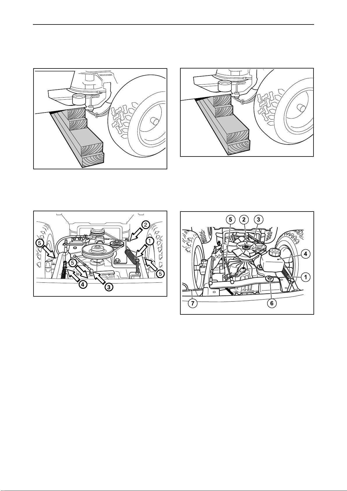
1
• Block-up the machine in front of the rear frame
and dismantle the rear wheels.
• Remove the cover from over the gear box.
2
Removing/installation of hydrostatic
transmission Rider 13 H/13 H Bio and
Rider 16 H
1
• Block-up the machine in front of the rear frame
and remove the back wheels.
• Remove the transmission cover.
2
• Release the tensioning wheel spring (1).
• Unfasten the clutch wire (2), and detach the belt
from the gear box pulley.
• Detach the gear and brake wires (3 and 4).
• Insert a garage jack under the gear box and
unscrew the gear box's five holder screws (5).
3
• Lower the garage jack and pull out the gear box.
• Installation of the gear box is carried out in the
reverse removing gear box order
• After installation, check that the clutch, brake
and gear wires are correctly adjusted (see
“Checking and adjusting brake wire”, “Checking
and adjusting gear control” and “Checking and
adjusting freewheel clutch”).
• Release the tensioning wheel spring (1).
• Remove the fan (2), it is held by a circlip.
• Work off the drive belt (3).
• Remove the oil tank (4).
• Release the brake wire spring and remove the
brake wire from the brake lever (concealed under
the oil tank).
• Release the hydrostatic transmission link (5) in
the front ball joint.
• Remove the screw (6) holding the arm.
• Remove the freewheel clutch control (7) with its
spring.
www.mymowerparts.com
English – 37
Page 40
For Husqvarna Parts Call 606-678-9623 or 606-561-4983
Reparation instructions
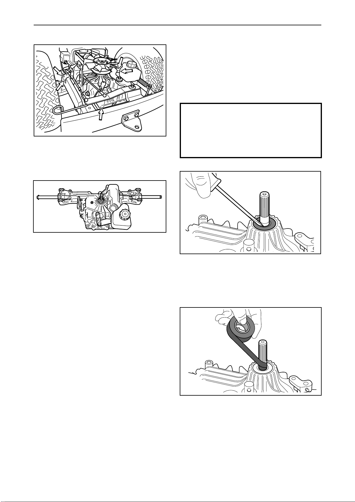
3
Insert a garage jack under the hydrostatic transmission and loosen its five holder screws.
4
Replacing hydrostatic transmission axle
sealing collars
Sealing collar replacement - input axle
Remove the cooling fan, it is held by a circlip. Remove the pulley from the input axle by pulling it
upwards and then removing the circlip under the
pulley.
IMPORTANT INFORMATION
The area around the sealing collar must be
absolutely clean! If the hydrostatic oil is
contaminated with dirt, this can lead to a
shorter hydrostatic transmission
operational life.
1
• Lower the garage jack and pull out the
hydrostatic transmission.
• Installation of the hydrostatic transmission is
carried out in the reverse hydrostatic transmission removing order
• After fitting the brake wire and hydrostatic
transmission wires, check that they are
correctly adjusted (see “Inspection and
adjustment of brake wire” and “Inspection and
adjustment of speed control”). Check also the
oil level in the hydrostatic transmission, and top
up if necessary. Check the setting of the
neutral position switch on machines with
hydrostatic transmission, see ”Electrical
system\Microswitch neutral position”.
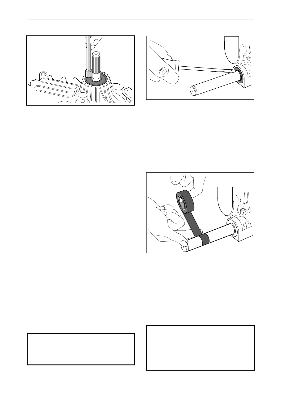
• Clean the input axle and the area around the
sealing collar of all dirt and rust.
• Insert a screwdriver between the sealing collar and
the axle and bend the sealing collar out of the axle
housing with a twisting motion.
2
• Wrap insulation tape around the input axle to
protect the new sealing collar from damage to
splines and grooves.
Start by wrapping from the bottom and continue
upwards over the axle until the entire axle is
wrapped in tape.
38 – English
• Lubricate the axle and the inside of the new
sealing collar with grease so that the collar can
slide easily.
www.mymowerparts.com
Page 41
For Husqvarna Parts Call 606-678-9623 or 606-561-4983
Reparation instructions
3
• Clean the outgoing axle and the area around the
• Place the sealing collar on the axle with the
smooth side upwards, and
downwards.
• Use the thick end of a 1/4" extender to
knock down the sealing collar until the upside of
the collar is level with the axle housing's upper
edge.
Move the extender in a circle around the sealing
collar so that it is evenly pressed down, all the
way around.
• Remove the insulation tape from the axle and
assemble the lower circlip and the pulley with the
hexagonal hub facing upwards.
carefully
press it
carefully
sealing collar of all dirt and rust.
• Insert a screwdriver between the sealing collar
and the axle and bend the sealing collar out of
the axle housing with a twisting motion.
2
• Fasten the fan and the washer and assemble the
upper circlip.
• Install the hydrostatic transmission in the ride-on
mower as indicated in the previous description
(see “Removal/installation of hydrostatic transmission”).
Sealing collar replacement - outgoing axles
1
Remove the rear wheels. Remove the circlips and
pull the wheels outwards. Do not mislay the key
that sits between the hub and axle. Use removing
tool 506 57 00-01 if necessary.
Remove the spacing sleeve and washer from the
wheel axle.
• Wrap insulation tape around the outgoing axle
from the start of the key-way and outwards until
even the circlip's groove is covered with tape.
This is done to protect the new sealing collar
from damage.
• Lubricate the axle and the inside of the new
sealing collar with grease so that the collar can
slide easily.
IMPORTANT INFORMATION
Dirt must not be allowed to get into the
transmission as this can shorten its
operational life.
www.mymowerparts.com
IMPORTANT INFORMATION
Before the sealing collar is completely
installed, check that the sealing collar's
metal spring reinforcement sits on the
side of the sealing collar which leads
inwards towards the transmission.
English – 39
Page 42
For Husqvarna Parts Call 606-678-9623 or 606-561-4983
Reparation instructions
3
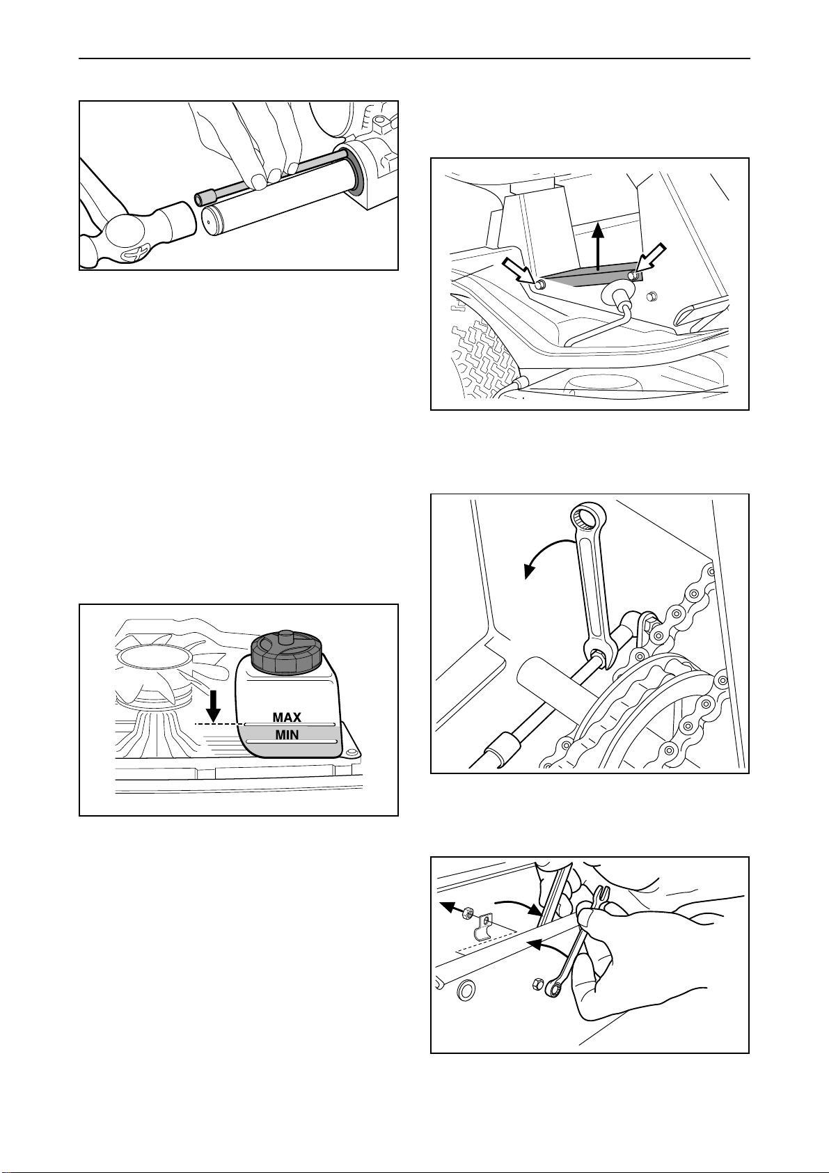
• Place the sealing collar on the axle, with the
metal spring inwards, and press it in
• Use the narrow end of a 1/4" extender to
carefully
reaches the bottom of the axle housing. Only
knock on the steel cover.
Move the extender in a circle around the sealing
collar so that it is pressed in evenly all the way
around and tight against the axle.
• Remove the insulation tape from the axle and
repeat, as is necessary, the entire procedure for
the second axle.
knock in the sealing collar until it
carefully
Replacing hydrostatic transmission wire
Removal of hydrostatic transmission wire
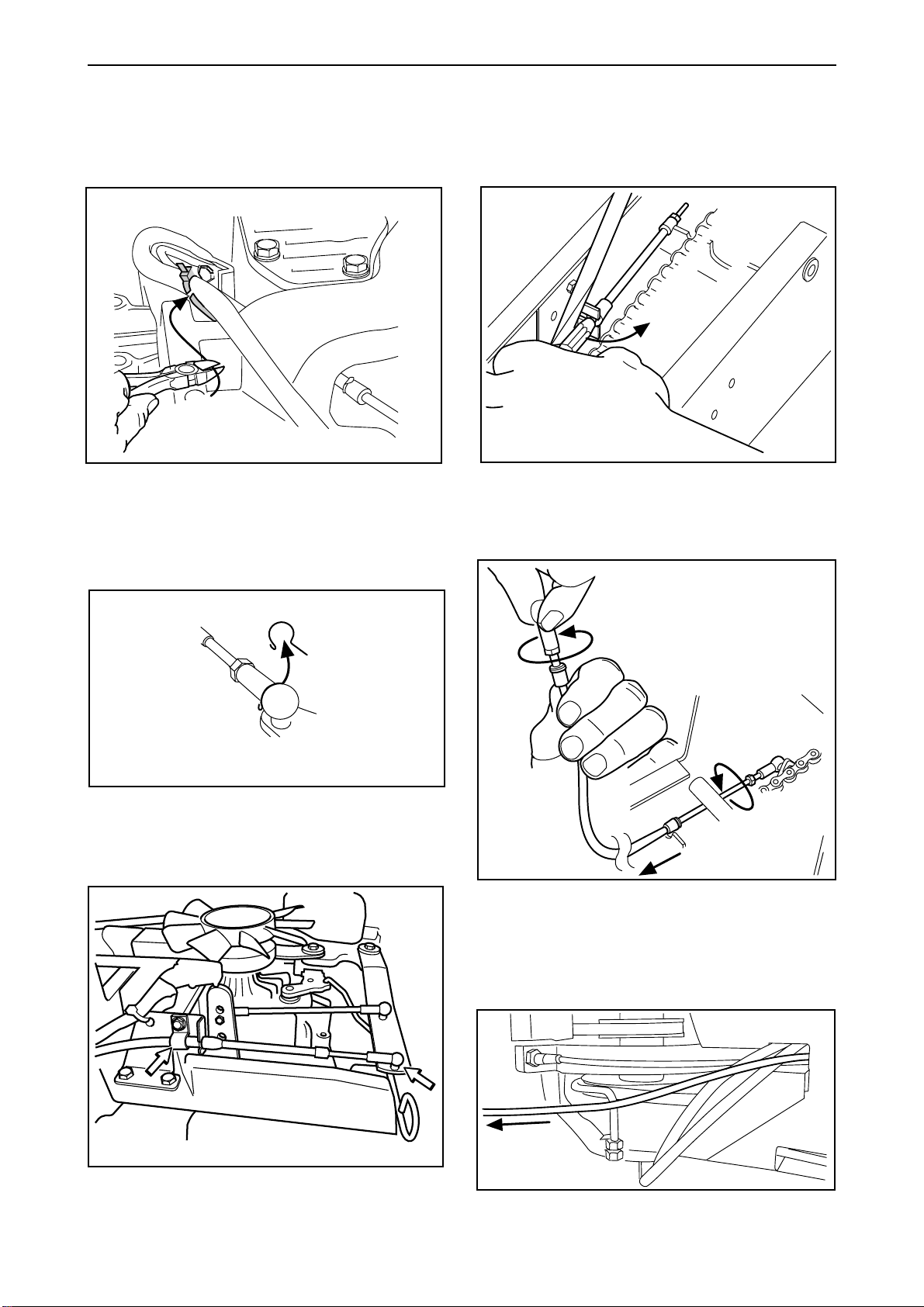
1
.
Remove the frame plate by undoing the screws
(two on each side).
2
• Replace the washer, spacing sleeve, key and
rear wheel on the axle. Fit the circlip that holds
the wheel and the plastic cover over the axle
end.
• Fill the transmission's oil container with SAE
10W30 oil until the oil level reaches the "MAX"marking.
• Bleed the transmission as directed in “Bleeding
of the hydrostatic transmission’s oil system”.
Loosen the hydrostatic transmission’s front lock nut
a 1/4 turn and remove the lock spring.
3
• Operate the ride-on mower and then check that
there is no oil leaking from the new axle sealing
collars.
• Check the oil level and top up if necessary after
test running.
40 – English
www.mymowerparts.com
Remove the hydrostatic transmission wire’s front
clamp fixed inside the middle bracket.
Page 43
For Husqvarna Parts Call 606-678-9623 or 606-561-4983
Reparation instructions
4. Remove the transmission cover. 7. Lift off the linkage and pull out the wire.
5
Follow the hydrostatic transmission wire backwards
towards the transmission and cut off the cable ties
round the wire.
6
8
Lift out the transmission wire with the linkage
attached.
9
Remove the lock spring at the transmission wire’s
rear linkage. Release the clamp holding the wire’s
casing.
Unscrew both ball joints from the hydrostatic
transmission wire.
10
Remove the entire hydrostatic transmission wire.
www.mymowerparts.com
English – 41
Page 44
For Husqvarna Parts Call 606-678-9623 or 606-561-4983
Reparation instructions
Refitting hydrostatic transmission wire
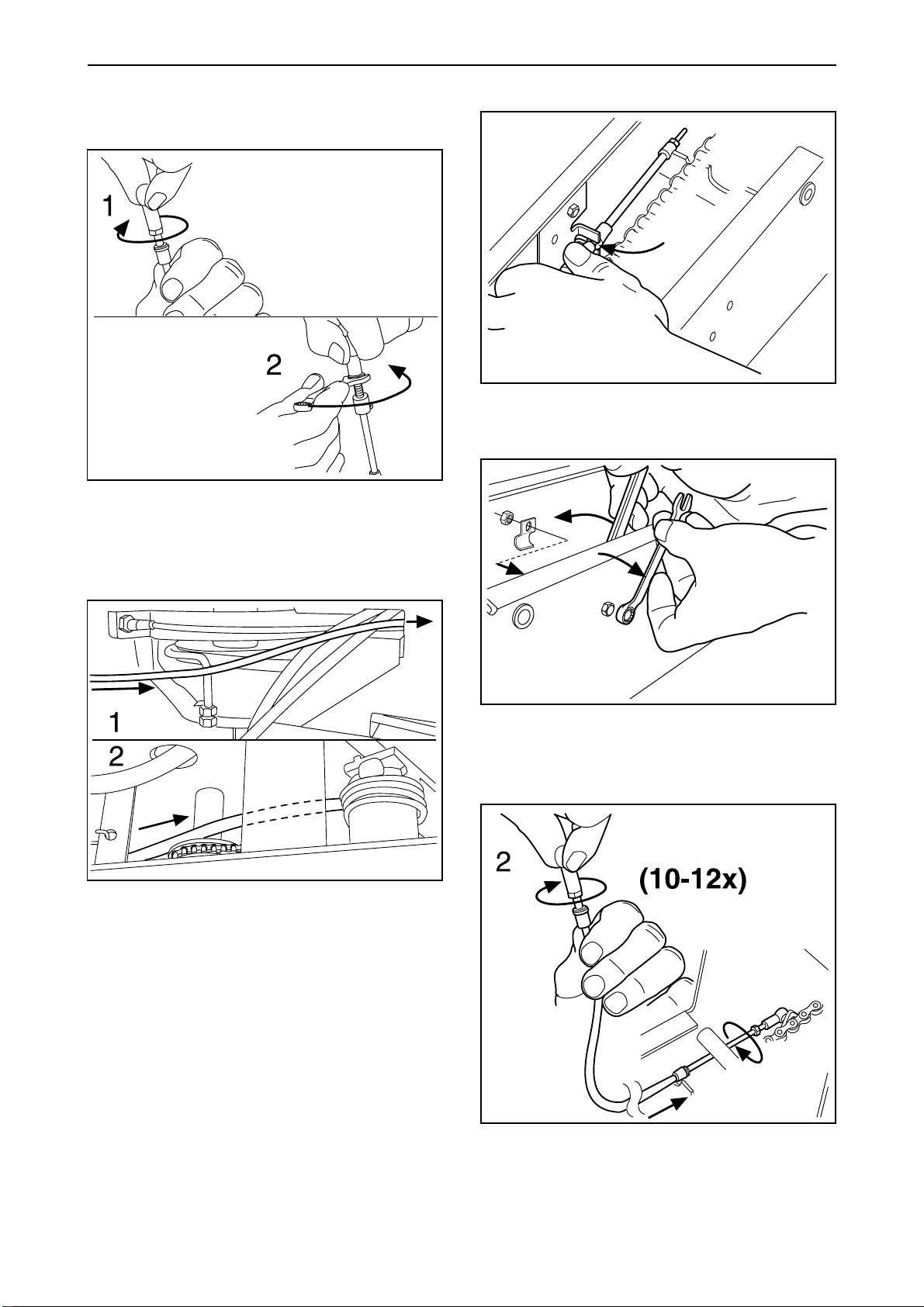
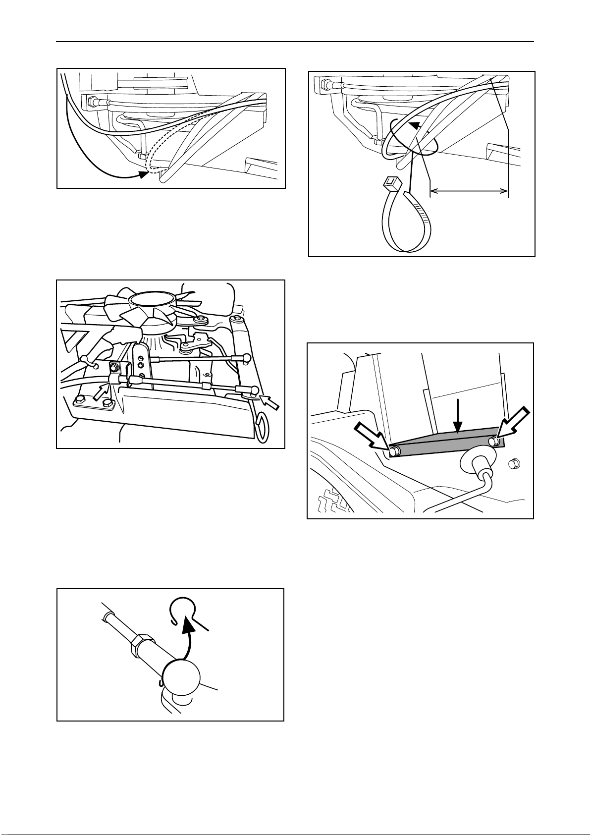
1
Screw the front ball joint onto the new transmission
wire and tighten the lock nut.
3
Press the wire casing in the front holder in the
middle bracket.
4
2
Run the wire through the mower so that it follows
the same route as the old wire.
Screw tight the hydrostatic transmission wire’s
clamp. Press the linkage in its holder and fit the
lock spring.
5
42 – English
Screw tight the linkage on the lower part of the
transmission wire. Screw 10-12 turns so that the
linkage has the correct length.
www.mymowerparts.com
Page 45
For Husqvarna Parts Call 606-678-9623 or 606-561-4983
Reparation instructions
6
Draw the transmission wire along with the other
cabling. Place the wire at the bottom in the clamp,
under the articulated steering’s bearing.
7
10
~80
Fix the hydrostatic transmission wire with a cable
ties.
11
Put the wire in position and screw tight the casing
with the rear clamp.
8. Adjust the wire as directed in “Inspection and
adjustment of speed regulator”. Connect the
rear linkage and fit the lock spring. Tighten the
rear lock nut for the linkage.
Refit the frame plate using the four screws.
9. Check the setting of the neutral position contact.
See ”Electrical system\Microswitch neutral
position”.
www.mymowerparts.com
English – 43
Page 46
For Husqvarna Parts Call 606-678-9623 or 606-561-4983
Reparation instructions
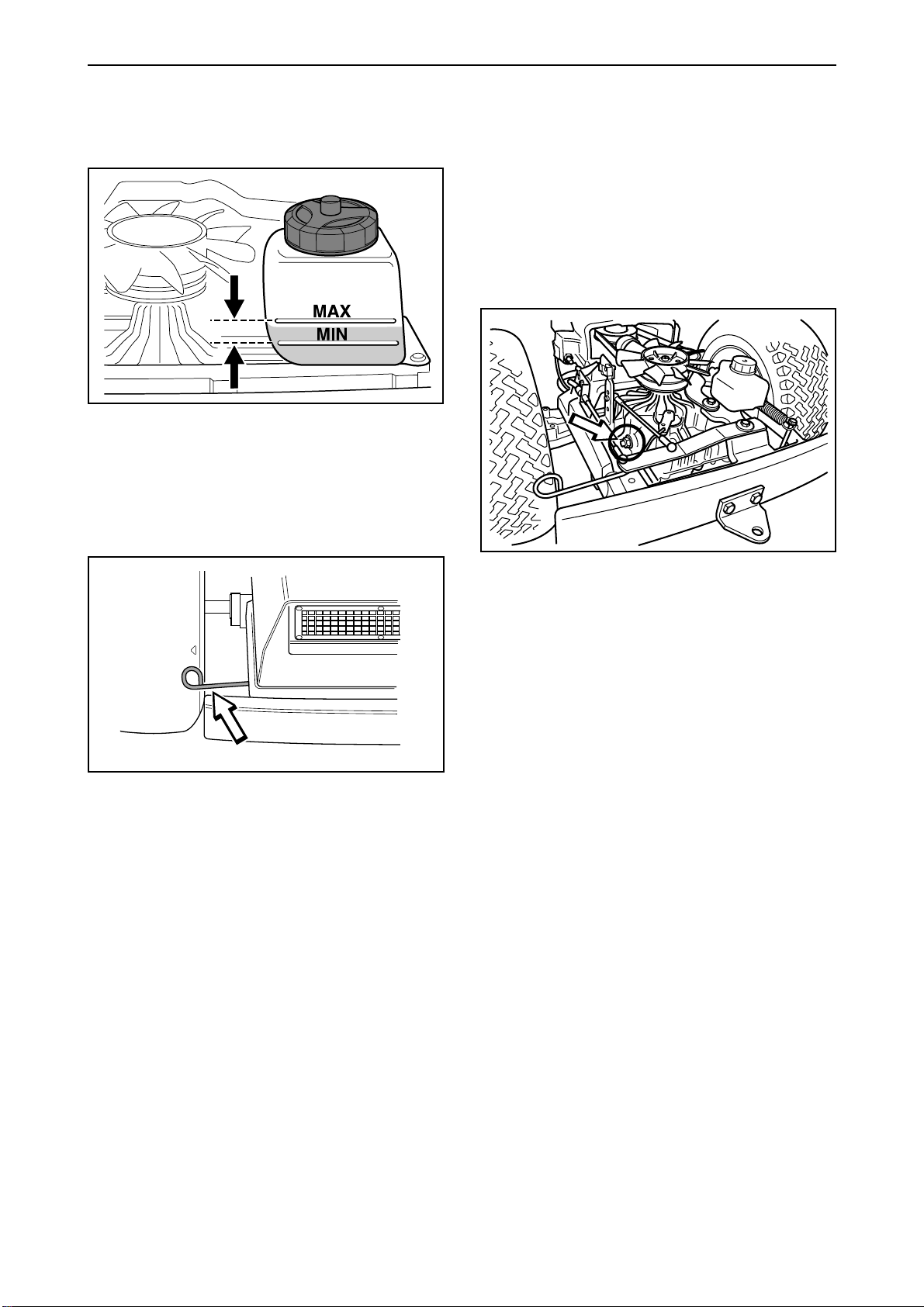
Bleeding the hydrostatic transmission
oil system
1
• Check the hydrostatic transmission oil level.
• Start the engine and set the throttle control to
idle.
2
Adjustment of transmission neutral
position
1. Bleed the hydrostatic transmission oil system.
2. Lift the back of the ride-on mower up so that the
wheels are off the ground and place blocks
under the machine.
3
• Repeat opening and closing the disengaged
clutch control whilst the front respective rear
pedals are alternately pressed down.
• When the mower starts to move set the governor
control lever to high idle.
3. Repeat quick starts and emergency stops until
the transmission responds as it should.
• Check also the oil level in the hydrostatic transmission, and top up if necessary.
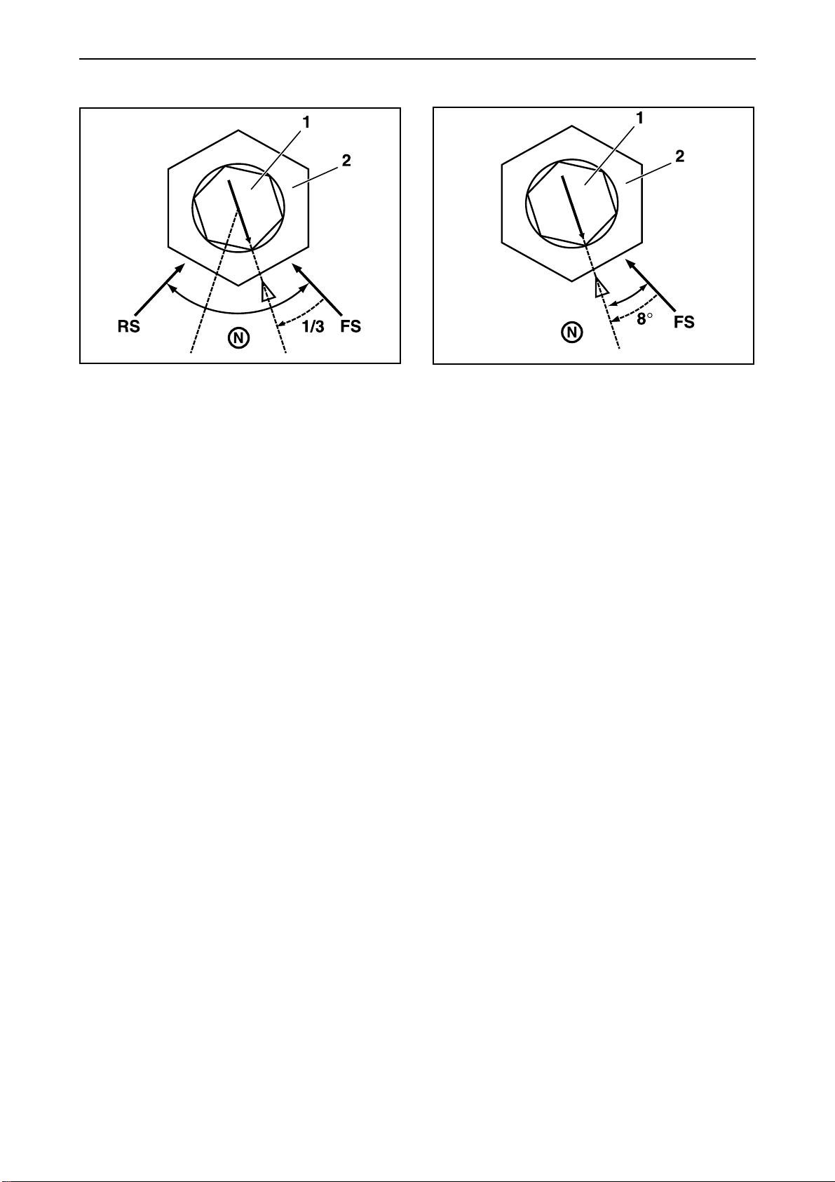
• The neutral position is adjusted by turning the
hexagonal axle on the transmission (see diagram).
• Start the engine and set the throttle control to full
throttle.
• Unscrew the hexagonal axle lock nut and turn
the axle clockwise until the drive shafts start to
rotate backwards.
• Make a mark on the top of the axle.
4. Check and top up with oil if necessary after test
driving.
44 – English
www.mymowerparts.com
Page 47
For Husqvarna Parts Call 606-678-9623 or 606-561-4983
Reparation instructions
4
1 = Axle
2 = Lock nut
• Slowly turn the axle anti-clockwise until the drive
shafts stop rotating backwards and make a mark
on the transmission housing (RS).
• Slowly turn the axle anti-clockwise until the drive
shafts start to rotate forwards.
• Slowly turn the axle clockwise until the drive
shafts stop rotating forwards and make a mark
on the transmission housing (FS).
• Turn the axle clockwise 1/3 of the distance
between the marked stop points.
• Hold the axle (N=8) firmly and tighten the lock
nut (N=17).
• Check that the drive shafts do not rotate in the
neutral position by slowly transferring the
steering arm to the neutral position from the
forwards and reverse positions.
5
1 = Axle
2 = Lock nut
If the drive shafts do not rotate backwards despite
the hexagonal axle having rotated a full turn, the
neutral position is to be adjusted in the following
way:
• Slowly turn the axle anti-clockwise until the drive
shafts start to rotate forwards.
• Slowly turn the axle clockwise until the drive
shafts stop rotating forwards and make a mark on
the transmission housing (FS) and the axle.
• Turn the axle clockwise 8° from the mark on the
transmission housing.
• Hold the axle (N=8) firmly and tighten the lock nut
(N=17).
Transmission maintenance
Oil change
Most garden owners do not have tools for or
experience of changing transmission oil. The
transmission probably has a longer operational life
than other ride-on mower components, this makes
transmission oil changes less important for most
customers. However, the transmission's operational
life is increased if oil changes are made.
If the ride-on mower is used
recommended to change the oil firstly after 50
hours use and every 300 hours use thereafter.
The transmission K 46 has a capacity for 2.2 litres/
2,35 USqt (SAE10W/30 engine oil, grade SF-CC).
The oil does not need changing in a manual
gearbox.
www.mymowerparts.com
professionally,
it is
English – 45
Page 48
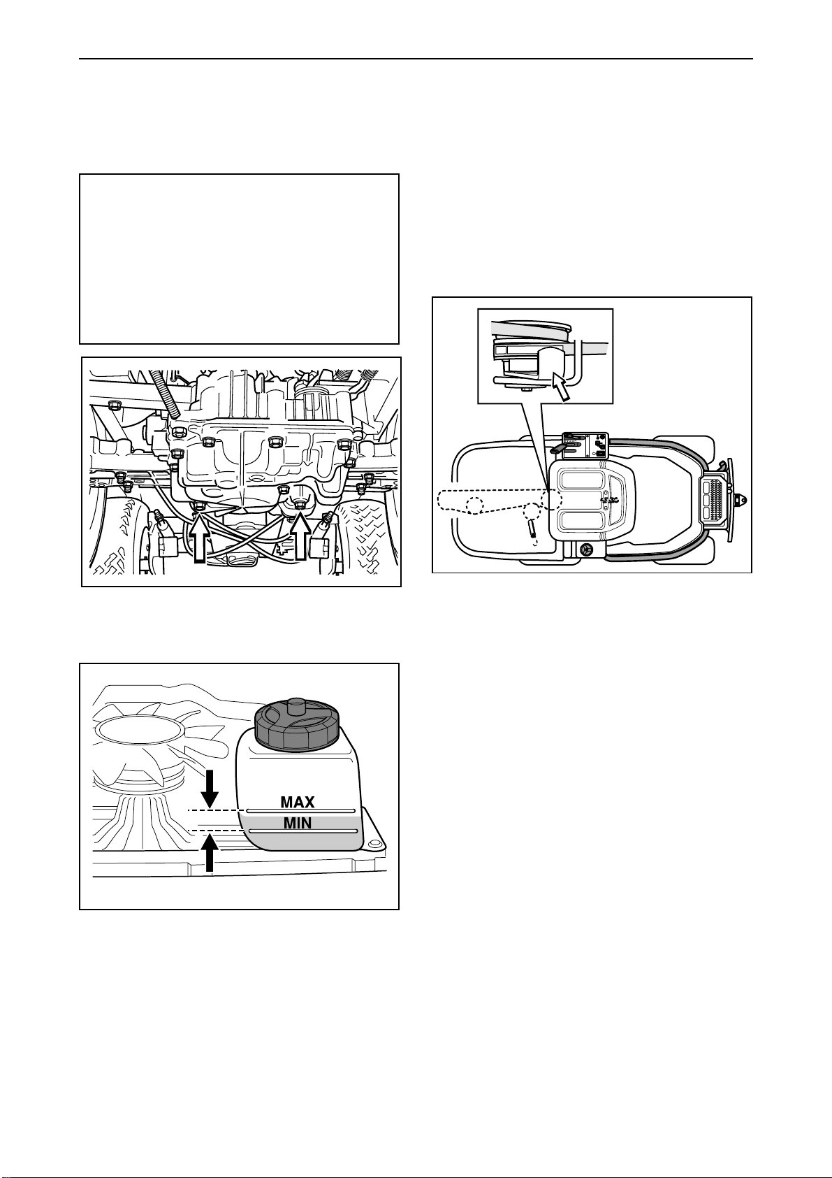
For Husqvarna Parts Call 606-678-9623 or 606-561-4983
Reparation instructions
Changing oil – Rider 13 and Rider 16
Empty the hydrostatic transmission with the two
plugs, width across flats 14 mm. The other screws
have smaller widths.
IMPORTANT INFORMATION
Spent engine oil is hazardous to health
and must not be poured out on the
ground or in the nature, but should be
handed in to a designated place for
recycling.
Avoid skin contact and wash any spillage
with soap and water.
Removing the belt
Rider 11, Rider 13 H, Rider 16 H och Rider 14
Pro
Starting point when Removing the belt:
• A deck is not mounted on the machine.
• The front part of the belt hangs loose.
The complete belt is removed as follows only if a
snow blade is to be fitted on the machine.
8
9
Fill up with oil in the oil tank.
Bleed the transmission as directed in “Bleeding of
the hydrostatic transmission’s oil system”. Top up
with oil after bleeding.
Test run the machine and recheck the oil level.
1. Loosen the belt guide and support pulley.
2. Loosen the belt tensioning pulley.
3. Prise the belt off the middle pulley and remove
the belt.
Reverse the above sequence to refit the belt.
46 – English
www.mymowerparts.com
Page 49
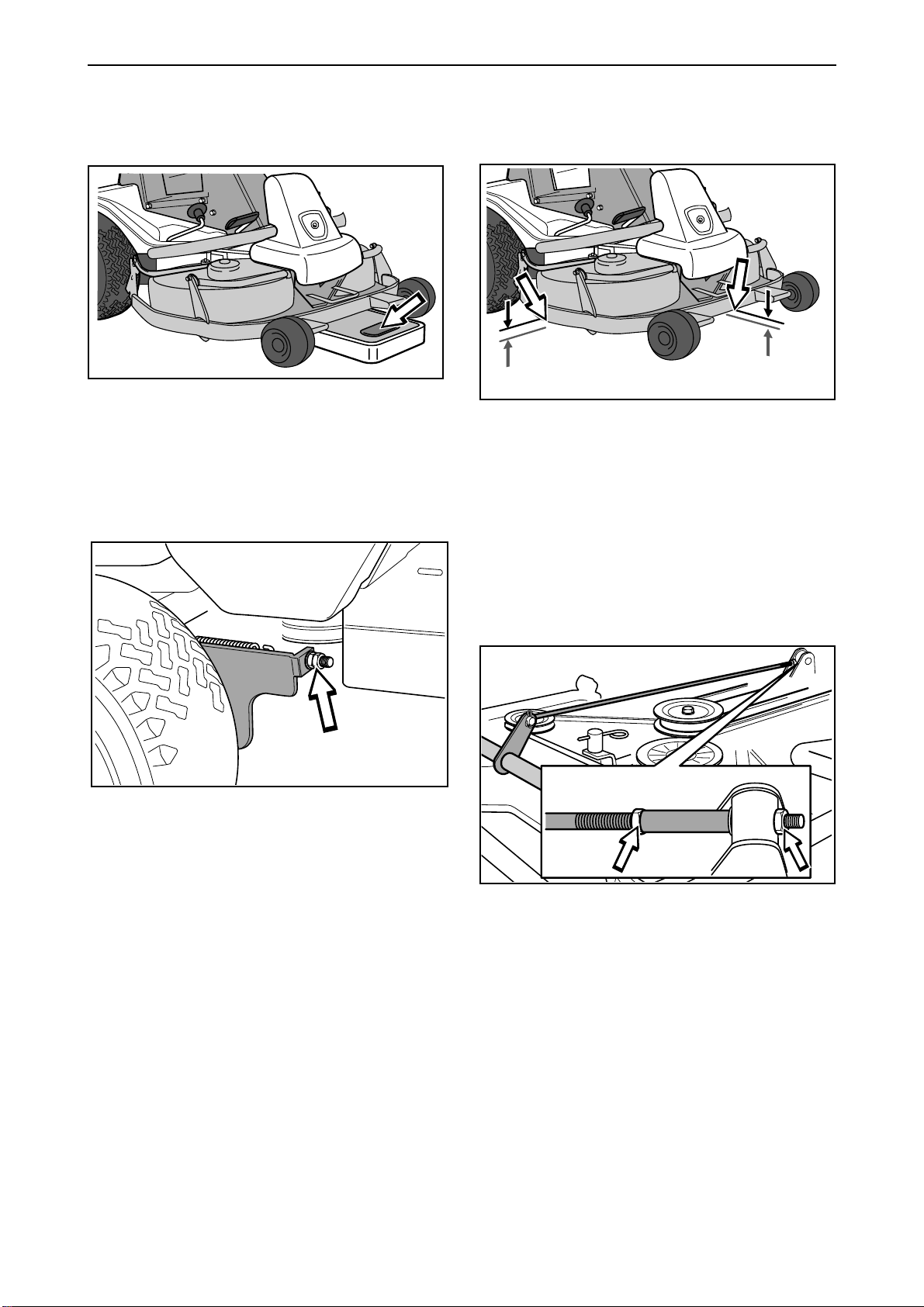
For Husqvarna Parts Call 606-678-9623 or 606-561-4983
Reparation instructions
Checking and adjusting mower deck
ground pressure
1 1
Check the tyre pressures (60 kPa/8,5 PSI).
Place a set of bathroom scales under the mower
deck's frame (front edge) so that the deck rests on
the scales.
2
Checking and adjusting mower deck
parallelism
Check the tyre pressures (60 kPa/8,5 PSI).
Place the ride-on mower on an even surface and
measure the distance between the ground and the
edge of the deck, at the front and rear of the cover.
The cutting unit should slope forwards slightly so
that the rear edge is 2-4 mm (1/8") higher than the
front edge.
Adjust the mowing deck's ground pressure with the
adjuster nuts placed behind the front wheels on
both sides of the ride-on mower. The ground
pressure should be between 12 and 15 kg/26.5-33
lbs and the springs tensioned equally.
2
Adjusting Rider 11 and Rider 13 H
2
• Remove the front cover and the right-hand
fender.
• Vertical adjustment of the mowing deck is made
with the adjuster nuts on the back edge of the liftstrut.
• Raise the mowing deck at the front edge by
shortening the lift-strut.
Lower the mowing deck at the front edge by
lengthening the lift-strut.
• Tighten the nuts against each other after the
adjustment.
• On completion of the adjustment, the deck's
parallelism should be re-checked.
• Fit the right-hand fender and the front cover.
www.mymowerparts.com
English – 47
Page 50

For Husqvarna Parts Call 606-678-9623 or 606-561-4983
Reparation instructions
2
Adjusting Rider 11 Bio and Rider 13 Bio
• Remove the front cover and the right-hand
fender.
• Unscrew the nut (1) on the parallel strut. Remove
the locking clips (3) and the parallel strut (2).
• Turn the fork anticlockwise to raise the cover’s
rear edge, clockwise to lower the cover’s rear
edge.
2
Adjusting Rider 16
• Remove the front cover and the right-hand
fender.
• Loosen the nuts on the parallel strut.
• Screw in (shorten) the strut to lower the rear
edge of the cover.
Screw out (extend) the strut to raise the rear
edge of the cover.
• Once adjustment is complete, refit the parallel
strut and clip and tighten the nut.
• Recheck the alignment of the cutting unit after
adjustment.
• Refit the right-hand fender and hood.
• Tighten the nuts after adjustment.
• On completion of the adjustment the unit’s
parallelism should be re-checked.
• Fit the right-hand fender and the front hood.
48 – English
www.mymowerparts.com
Page 51
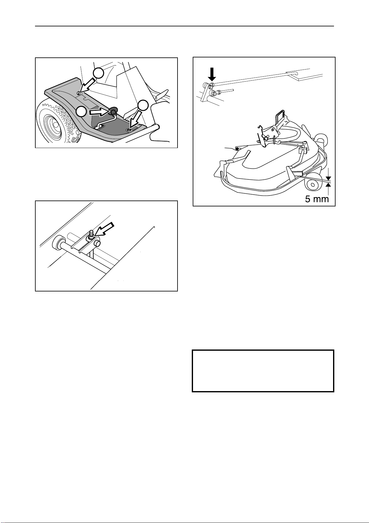
For Husqvarna Parts Call 606-678-9623 or 606-561-4983
Reparation instructions
Adjusting cutting height area
1
3
11
1
Remove the right-hand fender.
2
Adjusting cutting height
2
• Loosen the nuts on the height setting arm.
Raise or lower the entire mowing deck by screwing
the nuts up or down.
If the highest cutting height is raised by 5 mm
(3/16") the other fixed cutting heights will also be
raised by the same amount.
• Adjust so that the distance between the stop for
the lowest height setting and the protective
frame is 5 mm (3/16").
• Tighten the nuts.
• Check that the parallelism has not changed. If it
has changed, the parallelism must be
readjusted again.
• Check and adjust the cutting unit’s ground
pressure as set out (see “Checking and
adjusting cutting unit ground pressure”) if
necessary.
• Fit the nose.
IMPORTANT INFORMATION
The parallelism and height must be
adjusted again when changing the cutting
unit.
www.mymowerparts.com
English – 49
Page 52
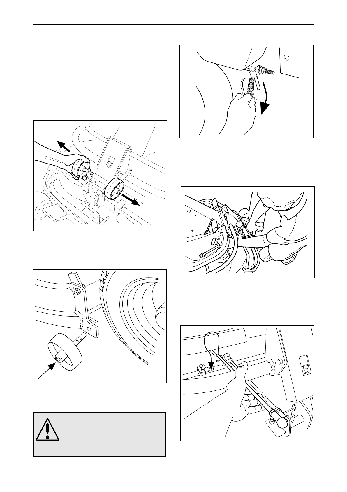
For Husqvarna Parts Call 606-678-9623 or 606-561-4983
Reparation instructions
Removing the cutting unit
BioClip and Combi unit
1. Apply the parking brake.
• Adjust the cutting height to its lowest setting.
• Remove the front cover.
2
3
Release the spring for the drive belt’s tensioning
wheel. Move the cutting height lever to the lower
position.
4
Release the two support wheels under the front
cover.
3
Fit the two support wheels on each side of the
lower part of the deck.
Place one foot on the front edge of the deck by the
wheel, and lift the front edge of the deck to simplify
releasing the height setting rod. Secure the rod in
the holder.
50 – English
WARNING!
Wear protective glasses when
removing the cutting unit. The
spring which tensions up the belt
can go off and cause personal
injury.
www.mymowerparts.com
Page 53
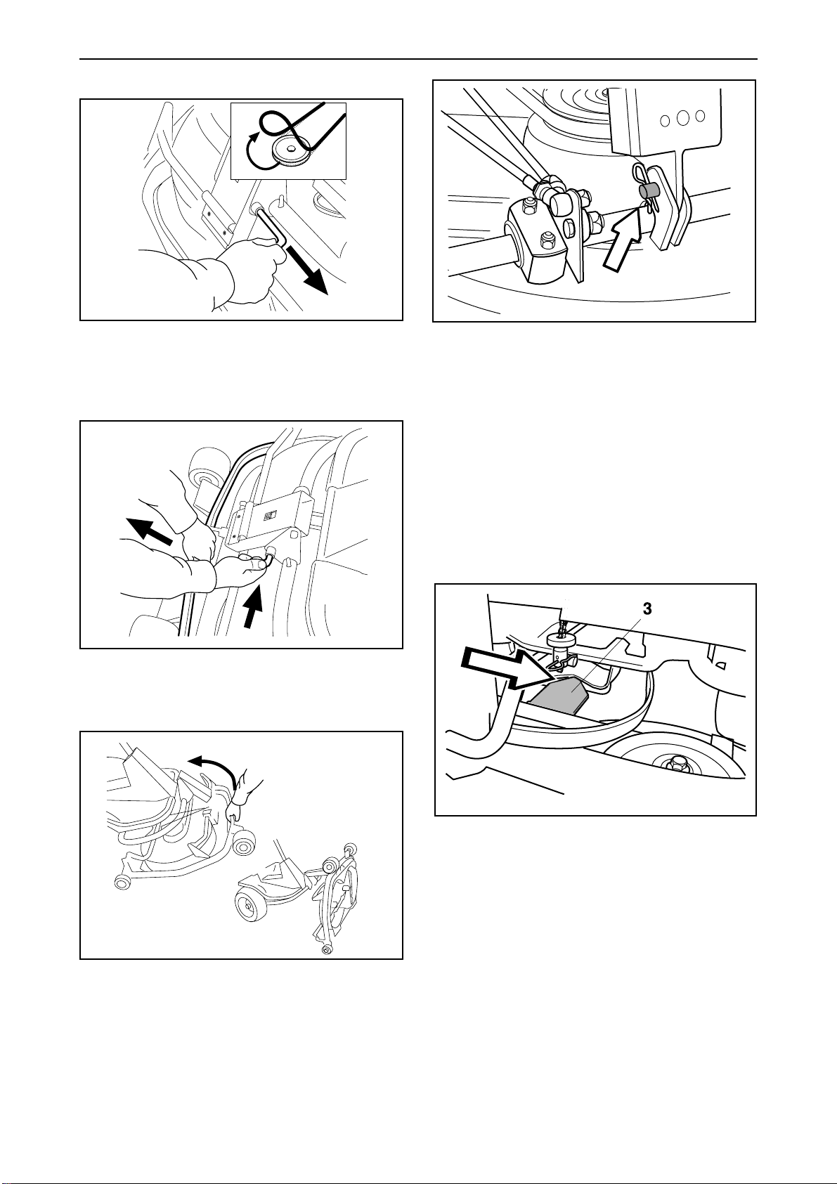
For Husqvarna Parts Call 606-678-9623 or 606-561-4983
Reparation instructions
5
1
2
Lift off the drive belt (1). Now pull out the pin (2).
Make sure not to trap your hand.
6
Pull the frame forwards and replace the pin.
7
If the cylindrical bolt, which is now holding the
mowing deck is removed, the mowing deck can be
lifted off.
To leave the service position
To leave the service position, reverse the
procedures set out in “Placing in the service position”. Make sure that the “lug” (3) on the mowing
deck enters the clamp correctly on the underside of
the machine, see diagram.
Grip the front edge of the deck, and pull out and lift
it up to the service position.
www.mymowerparts.com
English – 51
Page 54
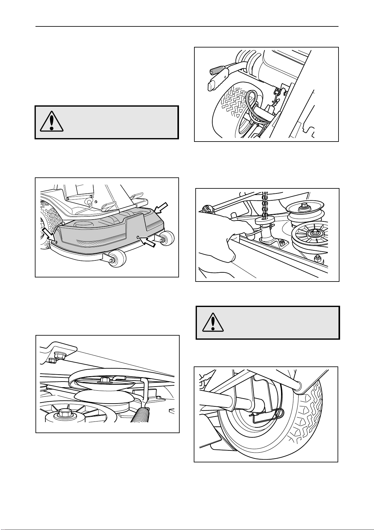
For Husqvarna Parts Call 606-678-9623 or 606-561-4983
Reparation instructions
Dismantling the cutting unit
Rear and side ejectors
1
• Place the machine on a level surface.
• Apply the brakes by pressing down the pedal
and lock using the pushbutton.
WARNING!
Wear eye protection and work
gloves when working on the
mowing deck.
2
4
Lower the mowing deck to the mowing position with
the lifting lever. Set the lowest mowing height with
the mowing height lever.
5
Remove the front cover. Remove the right and left
folding cover.
3
Raise the mowing deck to the transport position
with lifting lever.
Work off the belt from the mowing deck’s rear
pulley.
Remove the hairpin spring holding the lifting chain
in the mowing deck.
WARNING!
The mowing deck will drop to the
ground when the lock pins are
removed. Risk for pinch injuries.
6
Remove the lock pins (safety pins) on both sides of
the back of the mowing deck.
52 – English
Fit the mowing deck in the reserve order.
www.mymowerparts.com
Page 55
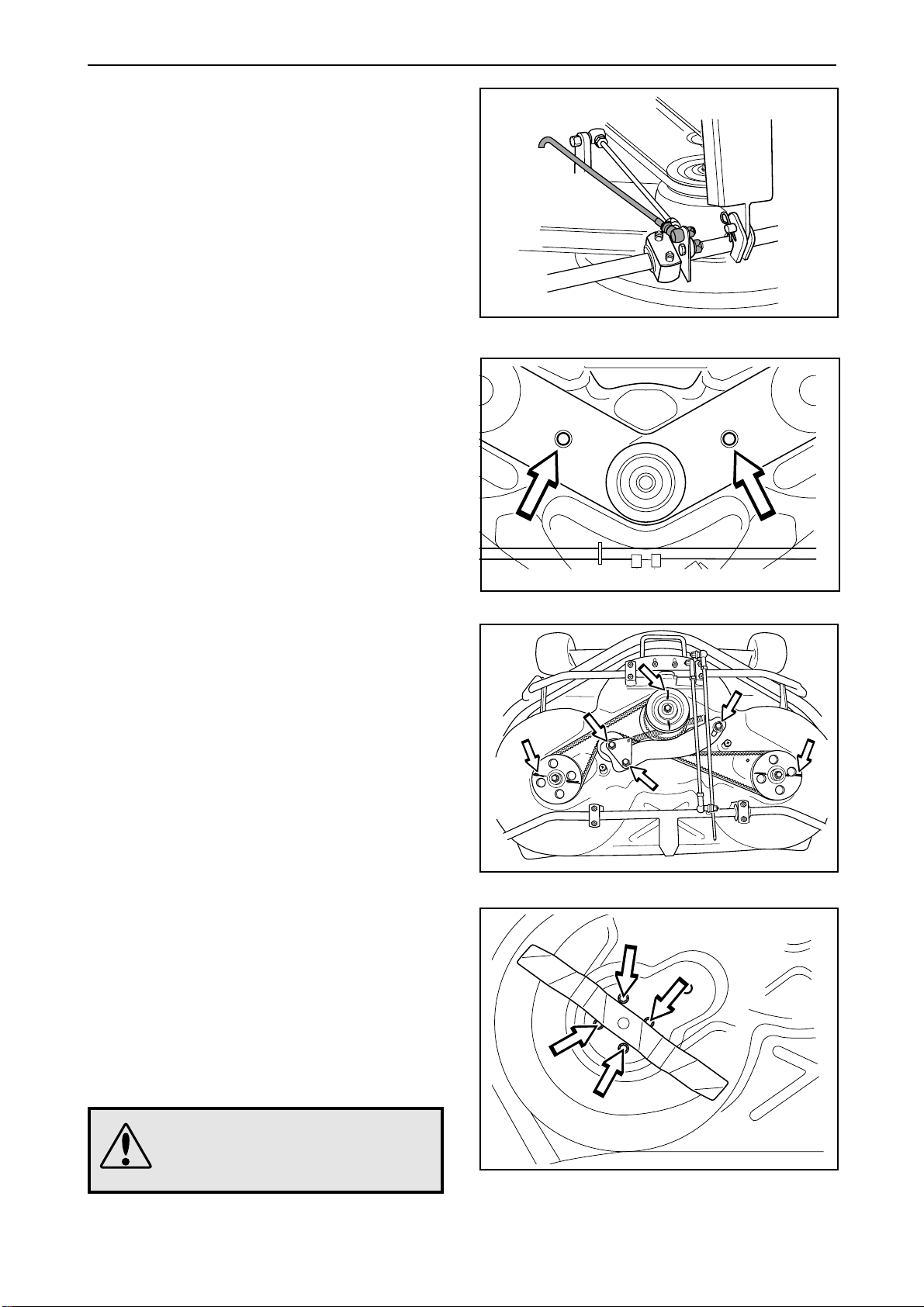
For Husqvarna Parts Call 606-678-9623 or 606-561-4983
Reparation instructions
Replacing the cutting unit’s belts
Belt replacement on BioClip 103 and Combi 103
There are two versions of BioClip 103. Version 1
has one toothed belt and version 2 has two. Combi
103 is only available with a tooth belt. The toothed
belts drive the blades and synchronise their
rotation. The belts are located under a cover on top
of the cutting unit.
1. Remove the cutting unit.
2. Remove the front bolt from the parallel strut and
tip the strut backwards. Push the height
adjustment strut forwards.
3. Loosen the two bolts holding the protective
hood and then lift off the hood.
Useful hint: Mark the positions of the blades on
the respective pulley using a felt-tip pen.
BioClip 103 Versions 1 and 2, Combi 103
4. Version 1 and Combi 103:
Loosen the three bolts 1/2 - 1 turn. Press the
sides of the belt together to give maximum
slack and tighten one of the bolts. Replace the
belt and tighten as shown (see decal on cover).
Set the blades at 90º to each other and loosen
the bolt again. The spring ensures the correct
belt tension. Check the positions of the blades
again and adjust if necessary by repositioning
the belt on the teeth. Tighten the three bolts to
45 Nm/32 lbft.
4. Version 2:
Loosen the nuts on the eccentric plate and turn
this away.
Loosen the four nuts (see diagram) holding the
outer blade bearing enough so that the bearing
can be moved.
Slide the blade bearing in towards the centre
bearing and pry off the upper belt.
BioClip 103 Versions 1 and 2, Combi 103
BioClip 103 Version 1, Combi 103
Repeat the procedure for the lower belt.
WARNING!
Protect your hands by wearing
gloves when working with the
blades.
www.mymowerparts.com
BioClip 103 Version 2
English – 53
Page 56
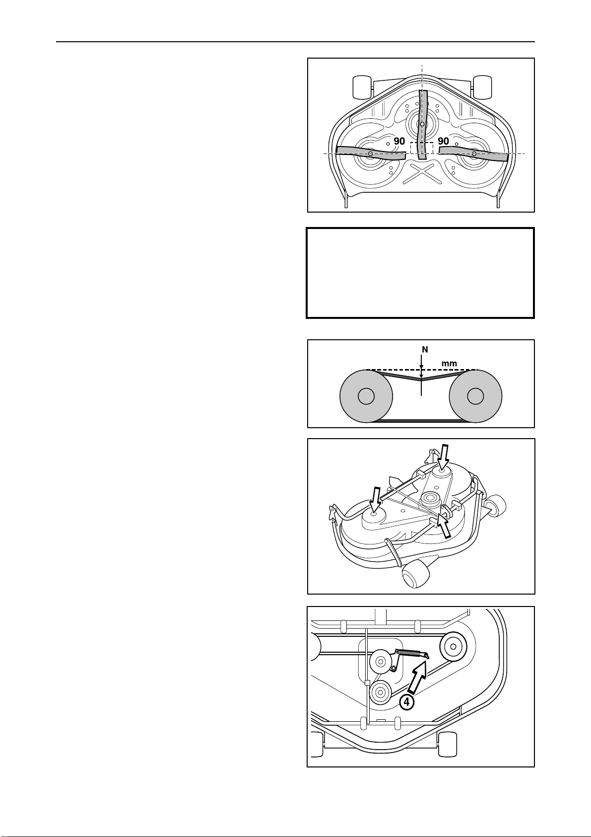
For Husqvarna Parts Call 606-678-9623 or 606-561-4983
Reparation instructions
5. Version 2:
Assembly: First fit the lower belt and then the
upper belt.
Ensure the blades are positioned as set out in
the diagram, at 90 degrees to each other,
otherwise the belts must be adjusted. When the
blade bearings are loose the belts can be
moved around to the next tooth.
Tighten the nuts enough so that the bearings
rest against the cutting hood but still can be
moved.
Tension the belt by turning the eccentric adjuster
on top of the cutting hood. Tighten the nut.
IMPORTANT INFORMATION
Tighten all nuts on the blade bearings.
6. Version 2:
When the belt moves (d) = 7 mm/1/4" inwards
with a force of (p) = 10 N/2 lb, the belt tension is
correct.
7. Version 1 and 2 as well as Combi 103:
Fit the protective cover over the belts and
replace the parallelism arm.
Belt replacement on BioClip 90
The BioClip 90 is driven by a toothed belt that
synchronises rotation of the blades. The belt is
located under the cover of the cutting unit.
When changing the belt on BioClip 90, follow the
above description, items 1-7 for version 2.
NOTE!
BioClip 90 only has 1 belt, tension (d) = 8 mm/5/16",
(p) = 7 N/1,5 lb.
On a BioClip 90 and all 103 units the
blades should have a relative position 90°
between blades. In all other cases the
blades can collide and cause serious
damage to the cutting unit.
(p)
(d)
Belt replacement on the mowing deck with side
or rear ejection, BioClip 112 and Combi 112
The blades on mowing decks with ”collision-proof”
blades are driven by a V-belt. Proceed as follows to
replace the
V-belt:
1. Remove the cutting unit, see page 31.
2. Undo the bolt on the lift strut and the two screws
on the cover. Lift the cover off the cutting unit.
3. Loosen the spring (4) that tensions the V-belt
and pry off the belt.
The new belt is fitted in the reverse order.
54 – English
www.mymowerparts.com
Page 57
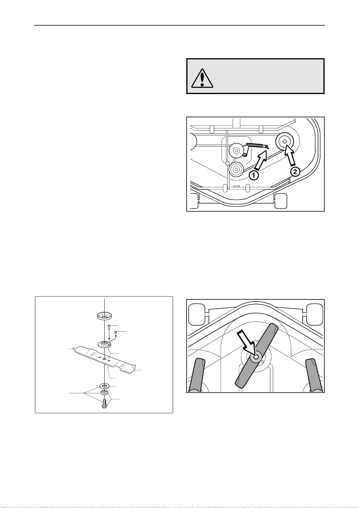
For Husqvarna Parts Call 606-678-9623 or 606-561-4983
Reparation instructions
Replacing the break-pin (BioClip 90, 103
and Combi 103)
The blades are fitted with a shear pin to protect the
mowing deck and its drive when colliding with
obstacles. A domed, spring friction washer is fitted
to each blade bolt. The washer must always be
replaced with a new washer when replacing the
shear pin. Otherwise the break-pin can break
causing the blades to collide.
Only use original spare parts. A set containing a
blade, break-pin and friction washer can be
purchased from your dealer.
1. Put the unit in the service position, see “Placing
in the service position”.
2. Remove the blade (2A) by removing the blade
bolt with washer and friction washer (2B).
3. Remove the remains of the broken break-pin
(3).
4. Make sure the contact surfaces (4) on the blade
and the blade mounting are free from metal.
Clean if necessary.
5. Fit one new break-pin (5) in the blade
mounting.
6. Fit the blade (6), make sure it is fitted as
illustrated.
7. Fit a new friction washer (7) with the concave
face turned towards the blade.
Removal of blades with bearings
WARNING!
When working with the mowing
deck, use protective glasses and
gloves.
1
• Release the spring which tensions the V-belt and
twist off the belt.
• Unscrew the screw which holds the pulley (2)
and detach the pulley, a puller may be needed
for this. Do not lose the key which is found
between the pulley and the axle.
8. Fit the blade bolt with washer (8). Tightening
torque 45-50 Nm (4,5-5 kpm/32-36 lbft)
5
3
2A
2B
4
6
4
7
8
2
Unscrew the screw which holds the blade and
remove the screw, washer and blade.
www.mymowerparts.com
English – 55
Page 58
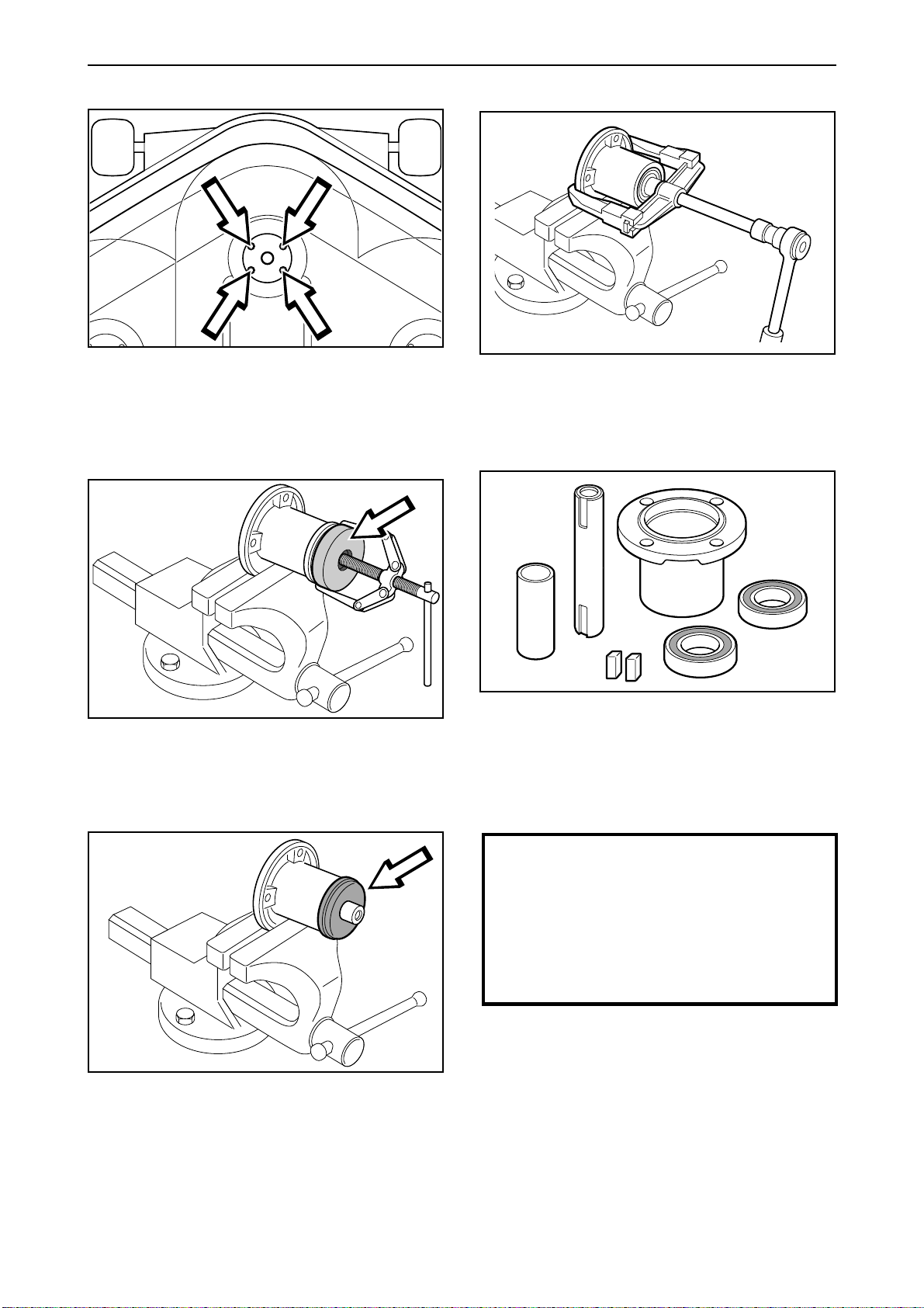
For Husqvarna Parts Call 606-678-9623 or 606-561-4983
Reparation instructions
3 6
Unscrew the four screws which hold the blade
bearing and remove the entire bearing packet from
the mowing deck.
4
Remove the hub using a puller. Do not lose the key
which is found between the pulley and the axle.
5
• Press out the axle with a puller.
• Knock out the bearings and remove the spacer.
7
The entire packet can be bought as a complete set
with axle housing, axle, spacer and bearing.
Installation is carried out in the reverse removing
order.
Remove the sheet metal safety washer.
56 – English
www.mymowerparts.com
IMPORTANT INFORMATION
When tightening the screws for the blade
shafts the screws on the transmission
side should always be tightened first,
followed by the blade screws.
The friction washer must be replaced
when replacing the shear pin.
Ensure that the axle is fixed in the same direction
as it was removed, if not the keys will not fit into the
key-way.
Tighten the blade bearings to a torque of 20–25
Nm/14-18 lbft.
Page 59
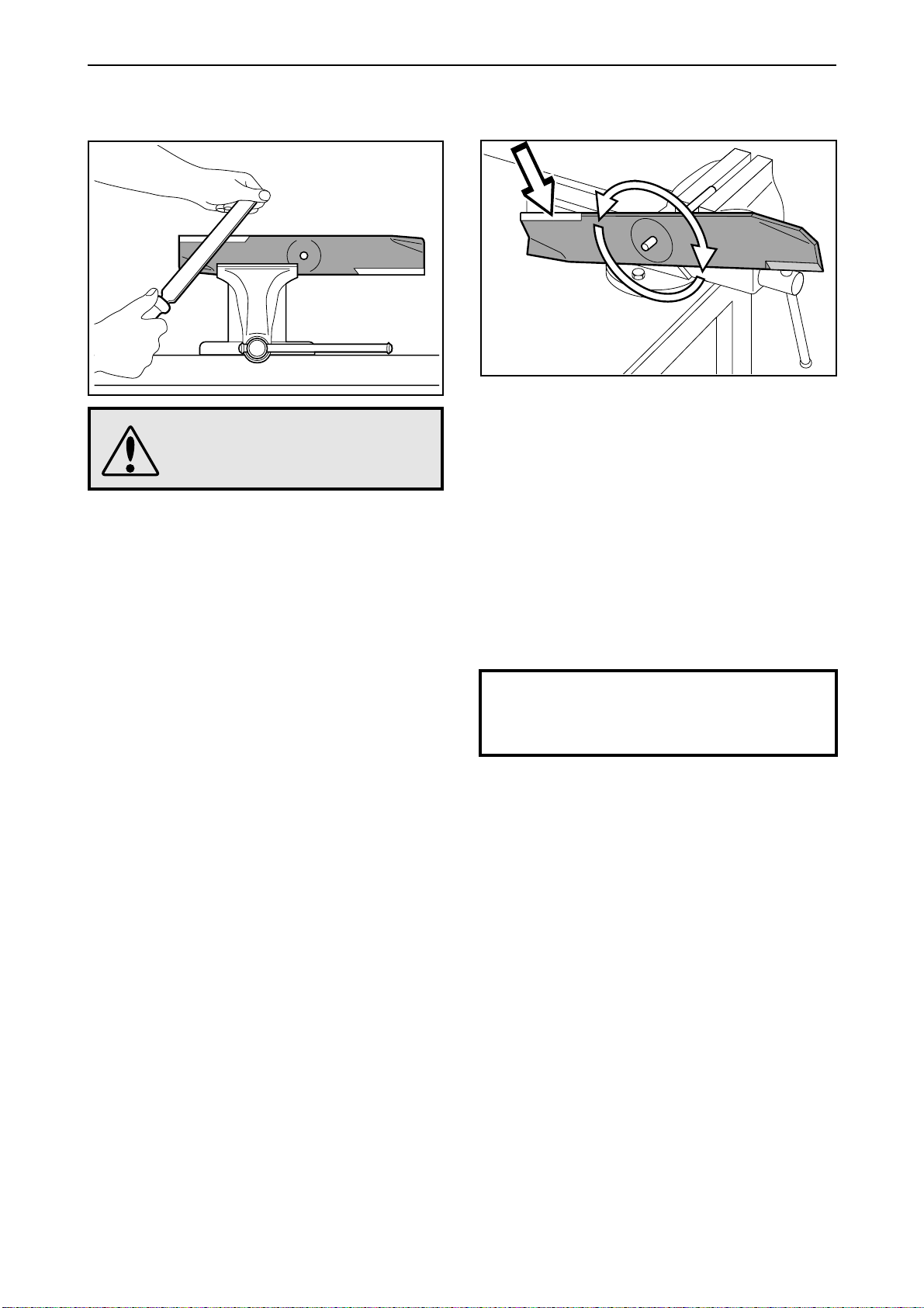
For Husqvarna Parts Call 606-678-9623 or 606-561-4983
Reparation instructions
Grinding and balancing of blades
1
2
Balance the blade as follows:
WARNING!
When working with the blades,
use protective gloves.
• Remove the blades according to the decription in
the previous section.
• Clamp the blade in a screw vice and file it so that
it becomes sharp.
• Fix, for example, a mandrel horizontally in a
screw vice according to the diagram.
• Push the blade onto the mandrel via the hole in
the centre of the blade and check that the blade
balances evenly. The diagram shows a blade
which needs to be adjusted, it must be ground
further to obtain the correct balance (at the
arrow).
• Installation is carried out in the reverse removing
order.
IMPORTANT INFORMATION
The friction washer must be replaced
when replacing the shear pin.
www.mymowerparts.com
English – 57
Page 60
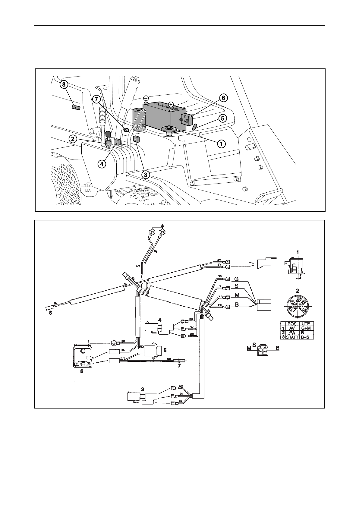
For Husqvarna Parts Call 606-678-9623 or 606-561-4983
Electrical system
Circuit diagram Rider 11
1. Microswitch, seat
2. Ignition lock
3. Microswitch, lifting lever
4. Microswitch, gear position
5. Fuse 15A
6. Starter relay
7. Engine/charging
8. Engine/stop
58 – English
Key to colour abbreviations in the electrical system
SV = Black
RD = Red
BR = Brown
BL = Blue
VT = White
GR = Green
GL = Yellow
www.mymowerparts.com
Page 61
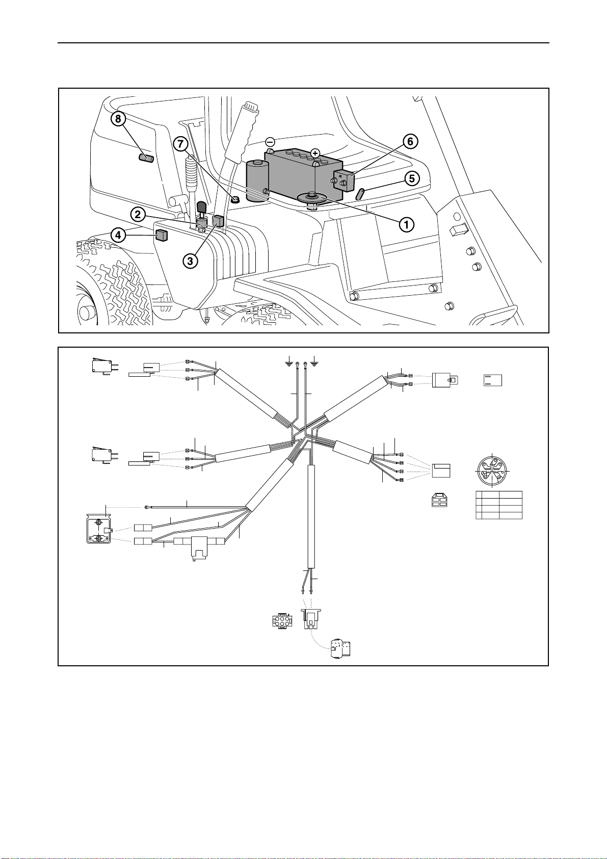
For Husqvarna Parts Call 606-678-9623 or 606-561-4983
Electrical system
Circuit diagram Rider 13 and Rider 13 Bio
SV 1160mm
4
3
BL 1050mm
6
RD 70mm
GL 1030mm
BR 740mm
BR 740mm
BL 1190mm
SV 510mm
BL 1190mm
5
RD 770mm
RD 980mm
GL 1030mm SV 650mm
RD 770mm
123
456
VT 450mm
12
7/8
VT 760mm
RD 980mm
SV 510mm
VT 450mm
SV 650mm
BL1050mm
SV 1160mm
VT 760mm
1
G
S
M
B
S
M
GBL
2
S
MB
L
G
Pos.
Utf .
Av
1 G+M
På
2 B+L
Start3 B+L+S
1. Microswitch, seat
2. Ignition lock
3. Microswitch, lifting lever
4. Microswitch, gear position
5. Fuse 15A
6. Starter relay
7. Engine/charging
8. Engine/stop
Key to colour abbreviations in the electrical system
SV = Black
RD = Red
BR = Brown
BL = Blue
VT = White
GL = Yellow
English – 59
www.mymowerparts.com
Page 62
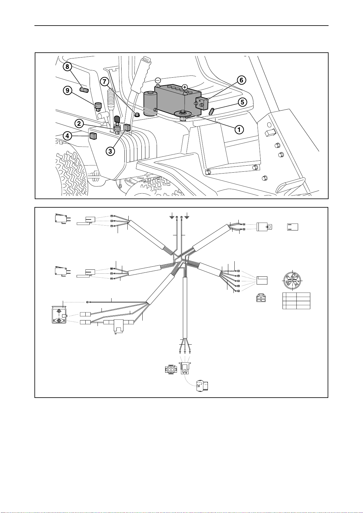
For Husqvarna Parts Call 606-678-9623 or 606-561-4983
Electrical system
Circuit diagram Rider 16
SV 1160mm
4
3
BL 1050mm
6
RD 70mm
GL 1030mm
BR 740mm
BR 740mm
SV 510mm
BL 1190mm
5
BL 1190mm
RD 770mm
RD 980mm
GL 1030mm SV 650mm
RD 770mm
VT 450mm GL 720mm
123
123
456
7/8/9
VT 760mm
RD 980mm
SV 510mm
VT 450mm
SV 650mm
BL1050mm
GL 720mm
SV 1160mm
VT 760mm
1
G
S
M
B
L
S
M
GBL
2
S
MB
L
G
Pos.
Utf .
Av
1 G+M
På
2 B+L
Start3 B+L+S
1. Microswitch, seat
2. Ignition lock
3. Microswitch, lifting lever
4. Microswitch, gear position
5. Fuse 15A
6. Starter relay
7. Engine/charging
8. Engine/stop
9 Engine/fuel valve
60 – English
Key to colour abbreviations in the electrical system
SV = Black
RD = Red
BR = Brown
BL = Blue
VT = White
GL = Yellow
www.mymowerparts.com
Page 63
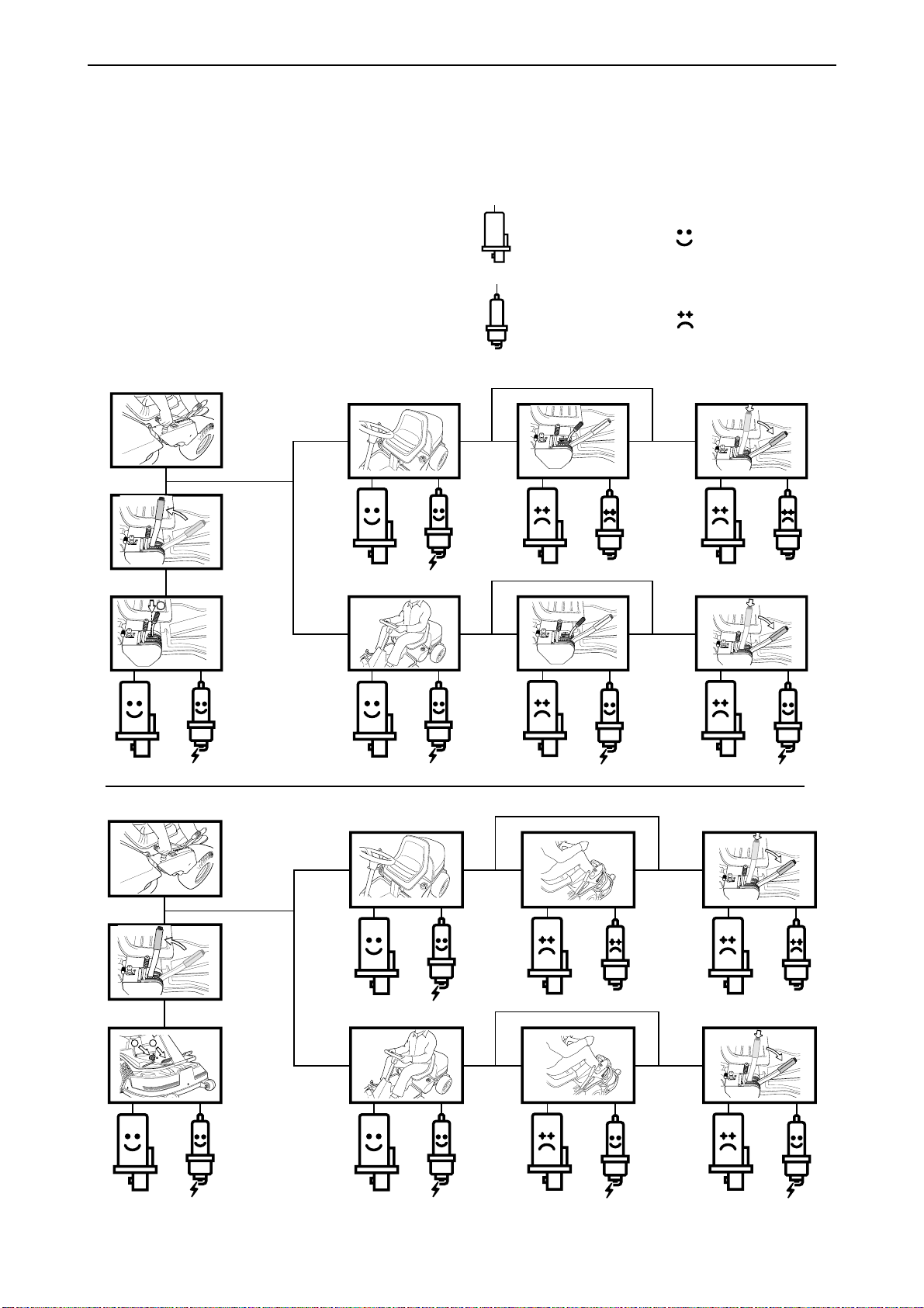
N
For Husqvarna Parts Call 606-678-9623 or 606-561-4983
Electrical system
Inspecting the safety system
The Rider is equipped with a safety system that
prevents starting or driving under the following
conditions:
The engine should only be possible to start when
the cutting unit is in its raised position and the
hydrostat pedals are in the neutral position.
The driver does not need to be seated in the
driver’s seat.
Make daily inspections to ensure that the safety
system works by attempting to start the engine
when one of the conditions is not met. Change the
conditions and try again.
Check that the engine stops if you temporarily move
out off the driver’s seat while the cutting unit is
lowered or the hydrostat pedals are not in the
neutral position.
Start engine
Ignition system
Works
Does not work
Rider 11
Rider 13, Rider 16
1
2
English – 61
www.mymowerparts.com
Page 64
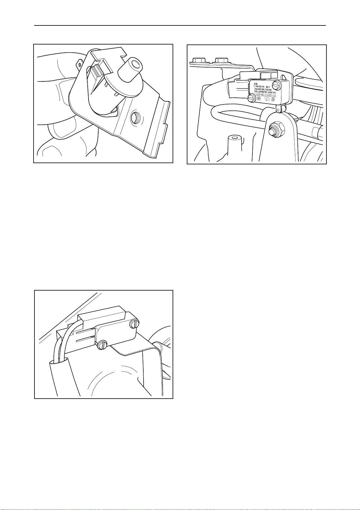
For Husqvarna Parts Call 606-678-9623 or 606-561-4983
Microswitch: Seat
1. Fold up the seat and remove the spring disc
with spring and spacer sleeve. The microswitch
holder is released.
2. Disconnect the cable connections from the
microswitch.
3. Press in the fasteners and remove the
microswitch from the holder.
Assembling is done in the reverse order without
setting.
Microswitch: Neutral Position
1. Remove the transmission cover.
2. Check the hydrostatic cable adjustment.
3. Adjust the microswitch so that it is activated by
the highest point in the hydrostatic arm’s path
when no driving pedal is pressed.
4. Adjust the microswitch so that it is definitely
activated by the hydrostatic arm, but allows
extra motion (it must not bottom out). Tip: Hold
a feeler gauge between the switch and the arm
when making the adjustment.
Microswitch: Mowing Deck
1. Loosen the right-hand wing cover.
2. Remove the inner protecting plate on the gear
lever carrier.
3. Release the connector from the microswitch.
5. Replace the transmission cover.
4. Remove the microswitch.
Assembling is done in the reverse order without
setting.
62 – English
www.mymowerparts.com
Page 65
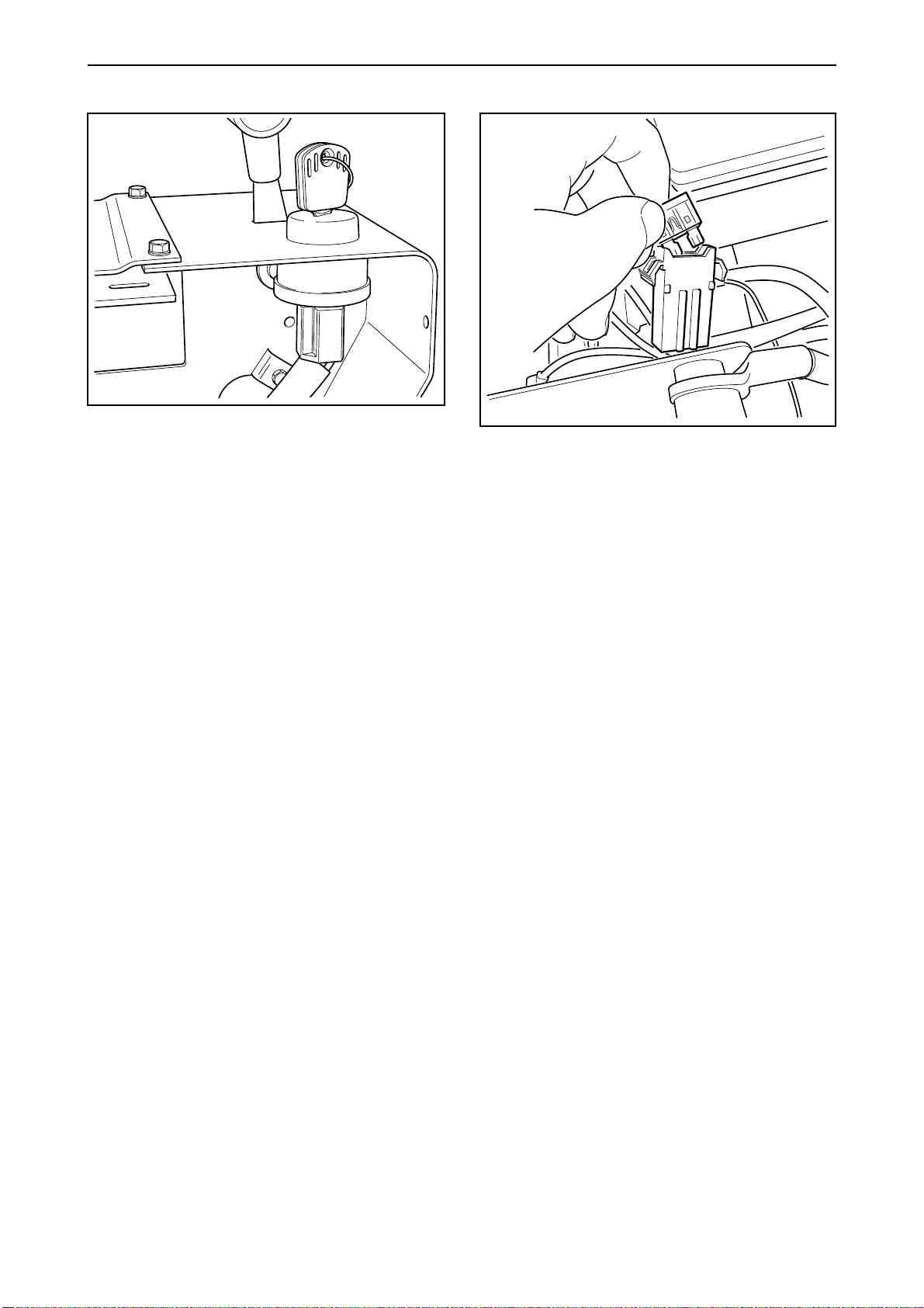
For Husqvarna Parts Call 606-678-9623 or 606-561-4983
Ignition and Starter Lock
1. Loosen the right-hand wing cover.
2. Remove the inner protecting plate on the gear
lever carrier.
3. Release the contact box from the ignition lock
by pulling it straight down.
4. Remove the ignition key and the rubber seal.
5. Remove the nut and the ignition lock.
Assemble the parts in the reverse order. Make sure
the connector ends up in the proper position (clicklock).
Main fuse
The fuse is placed in a detachable holder under the
battery case’s cover, in front of the battery.
Type: Flat pin, 15 A.
Do not use any other type of fuse when replacing.
A blown fuse is indicated by a burnt connector.
Pull the fuse from the holder when replacing.
The fuse is there to protect the electrical system.
If it blows again shortly after replacement, it is due
to a short circuit, which must be fixed before the
machine can be put into operation again.
www.mymowerparts.com
English – 63
Page 66
Bad contact on battery poles
Clean and lubricate with
copper paste
ENGINE WILL NOT START
Starter motor does not turn the
engine
No spark from spark plug
Discharged battery
No contact on starter relay
Starter motor and/or cable
connection defective
Heavily burnt electrodes
Bad ignition cable connection
Spark plug short circuited
Defective ignition coil
Fuel tank empty
Fuel stop valve does not open
Charge battery
Change battery
No current to relay
Relay defective
Change relay
Check connections
Change starter motor
Adjust electrode gap or
replace spark plug
Change the spark plug cap
Replace the spark plug
Change the ignition coil
Fill with fuel
No current to the valve or the
solenoid is defective
Channel from the fuel stop
valve blocked
Blown fuse
Bad or no earth contact
Defective ignition switch
Microswitch on the cutting
equipment’s lifting lever
defective or in wrong position
Defective microswitch under
seat
Microswitches by gear lever,
hydraulic pedal defective or in
wrong position (neutral pos)
Check cable connections or
replace the valve
Clean the channel with
compressed air
Change the fuse
Localise fault
Clean, lubricate with copper
paste. Tighten t h e e a r t h cable
Check cable connections or
replace the switch
Check cable connections or
replace the switch
Adjust the setting
Check cable connections or
replace the switch
Check cable connections or
replace the switch
Adjust the setting
Incorrect fuel supply
For Husqvarna Parts Call 606-678-9623 or 606-561-4983
No fuel to the carburettor
No fuel from the carburettor
(Spark plug dry)
Fuel filter blocked
Tank ventilator blocked
Fuel pump defective
Fuel pipes blocked or pinched
Needles and diffuser jets
blocked
Change the filter.
Clean or replace the fuel cap
Broken pump diaphragm
Impulse channel blocked
Clean or replace the pipes
Clean the carburettor with
compressed air
www.mymowerparts.com
Change the diaphragm
Clean the channel with
compressed air
Page 67
ENGINE STARTS BUT DOES NOT RUN SATISFACTORILY
Engine runs unevenly or lacks
power
Ignition fault
Defective spark plug
Incorrect ignition setting
Diode fault (V-twin engine)
Replace the diode
Heavily worn or blocked
Incorrect heating value
Incorrect contact gap
Incorrect pre-ignition position
Clean, adjust or replace the
plug
Change to a spark plug with
the right heating value
Check and adjust the contact
gap
Adjust the pre-ignition
Exhaust Dense Blue Black
smoke:
Engine damage
Carry out compression test
Engine overheating
Fuel fault
Wrong fuel used.
Fuel too old
Low octane value after long
period of storage
Replace fuel
Choke on
Check choke wire and
choke valve
Overloading
Change operating technique
Ignition fault
Defective carburettor
Too little fuel in tank
Dirty fuel filter
Dirt in fuel pipe
Pinched or leaking fuel pipe
Defective carburettor
Blocked air filter
Tank ventilator blocked
Spark plug has wrong heating
value
Defective pre-ignition
Diode fault (V-twin engine)
Incorrect setting
Partly or fully blocked needles
and diffuser jets
Fill the fuel tank
Change the filter
Clean or replace the fuel pipe
Incorrect setting
Blocked needle
Clean or replace the filter
Clean or replace the fuel cap
Change to right spark plug
Correct ignition setting
Replace the diode
Correct the setting
Clean the carburettor with
compressed air
Correct the carburettor setting
Clean the carburettor with
compressed air
www.mymowerparts.com
Too low or no oil in the engine
Insufficient cooling
For Husqvarna Parts Call 606-678-9623 or 606-561-4983
Blocked cooling fins or air
intake
Cooling fan damaged
Fill with right quantity and
quality of oil
Clean off dirt and leaves
Change the fan and clean the
fan cover
Page 68
Drive belt slips
Drive belt worn or covered in oil
and dirt
Drive belt’s adjuster pulley
defective
Clean or replace the drive belt
Broken spring. Replace
Lever jams. Lubricate
Machine runs slowly, lacks
power or no drive at all
No machine drive in either
direction
Key/keys missing or damaged
Hydrostatic transmission
Hydrostatic transmission
Engine shaft’s pulley
Wheel hub, axle
Spline on input axle in the
transverse axle damaged
Input shaft does not drive the
hydraulic pump
Defective pump components or
differential parts
Blocked oil filter
Low oil level in the hydrostatic
transmission or tank
Lever for “bypass valve” partly
extended
Defective accelerator
Key on transverse axle broken Replace the key
Damage inside transverse axle
Replace the key. Inspect the axle
and pulley for damage
Replace the key. Inspect the axle
and pulley for damage
Repair or replace the transverse
axle
Repair or replace the transverse
axle
Repair or replace the transverse
axle
Clean or replace the oil filter
Fill engine oil SAE 10W/30 to
correct level
Move to lever to the drive position
Tubular pin in regulating axle
sheared off. Replace
Control incorrectly adjusted or
damaged. Replace and adjust
Repair or replace the transverse
axle
www.mymowerparts.com
Brakes applied
Brakes incorrectly adjusted or
seized.
The hydrostatic transmission must not be opened during the warranty period.
For Husqvarna Parts Call 606-678-9623 or 606-561-4983
Lubricate the brake links. Adjust
Page 69
Engine slows with heavy load
Defective engine
Engine speed drops
Drive belt for transverse axle
Repair the engine
Belt worn or oily
Clean or replace the belt
Adjust the belt
Abnormal noise in transmission
Defective transmission
Drive belt
Hydrostatic transmission’s cooling
fan
Pulley on hydrostatic
transmission’s input shaft
Hydrostatic transmission
Bypass valve
Transmission overheated
Oil level too low
Check the belt tensioning
mechanism
Worn belt
Damaged impeller or runs against
foreign object
Pulley loose or damaged
Oil level too low
Blocked oil filter
The valve’s nozzle in wrong
position
Stop and let the transmission cool
down. Clean the cooling fins.
Fill engine oil SAE 10W/30 to
correct level
Lubricate the bearing or replace
the belt adjuster
Replace the belt
Clean or replace the fan
Tighten or change the pulley
Fill engine oil SAE 10W/30 to
correct level
Change the oil filter
www.mymowerparts.com
Repair
The hydrostatic transmission must not be opened during the warranty period.
For Husqvarna Parts Call 606-678-9623 or 606-561-4983
Page 70
Brakes do not work
satisfactorily
Brake linkage
Brake lining
Damaged or incorrectly adjusted
Worn or saturated in oil
Change linkage and adjust to right
setting
Change brake lining
The machine moves while in
neutral
Difficulty in changing gear
The machine cannot be towed
or pushed
Hydrostatic transmission
Accelerator
Hydrostatic transmission
Accelerator
Bypass valve
Internal fault on e.g. gear shift axle
Incorrectly adjusted or seized
Oil level too low
Internal fault on e.g. gear shift axle
Incorrectly adjusted or seized
Bypass valve only partly activated
Linkage damaged or seized
Internal fault in the hydrostatic
transmission
Repair or replace the hydrostatic
transmission
Lubricate and adjust
Fill engine oil SAE 10W/30 to
correct level
Repair or replace the hydrostatic
transmission
Lubricate and adjust
Pull out the control fully
Replace damaged parts. Adjust
Repair or change the hydrostatic
transmission
www.mymowerparts.com
The hydrostatic transmission must not be opened during the warranty period.
For Husqvarna Parts Call 606-678-9623 or 606-561-4983
Page 71

For Husqvarna Parts Call 606-678-9623 or 606-561-4983
www.mymowerparts.com
Svenska – 31
Page 72

For Husqvarna Parts Call 606-678-9623 or 606-561-4983
114 01 45-26
´®z+H.T¶6w¨
www.mymowerparts.com
2002W51
 Loading...