

Page 1

For Husqvarna Parts Call 606-678-9623 or 606-561-4983
Brush Cutters, Trimmers,
Pruners, Pruning Saws,
Hedge Trimmers, Ice Drills,
Blowers
Workshop Manual
101 90 74-26
www.mymowerparts.com
Page 2

For Husqvarna Parts Call 606-678-9623 or 606-561-4983
Workshop Manual
Brush cutters, Trimmers,
Pruners, Pruning saws, Hedge
trimmers, Ice drills, Blowers
Contents
General recommendations ______________________ 2
1. Starter __________________________________ 3
2. Ignition system ___________________________ 25
3. Fuel system _____________________________ 39
4. Centrifugal clutch _________________________ 81
5. Angle gear _____________________________ 107
6. Cylinder and piston ______________________ 119
7. Crankshaft and crankcase _________________ 147
8. Hydraulic unit ___________________________ 181
9. Cutting equipment _______________________ 191
10. Tools__________________________________ 209
The Manual covers the models:
265, 250, 252, 240/245
225 / 232 / 235 / 240 RBD
322/325
122, 32, Mondo
250PS, 235 P
225 H 60 / 225 H 75
225AI15, 225AI25
18H, 140B, 141B
132HBV, 225BV, 225HBV
© Copyright Husqvarna AB, Sweden
www.mymowerparts.com
1
Page 3

For Husqvarna Parts Call 606-678-9623 or 606-561-4983
General recommendations
The workshop used to carry out repairs must be equipped with
safety devices in accordance with local directives.
No one may carry out repairs without first having read and
understood the contents of this Workshop Manual.
The boxes below can be found in appropriate parts of this
manual.
WARNING!
!
NOTE!
This box warns of damage to material if the instruc-
tions are not followed.
The machine is type approved for safety in accordance with
applicable legislative demands with the equipment specified in
the Operator’s Manual. The assembly of other equipment or
accessories or spare parts not approved by Husqvarna can
result in the failure to meet these safety demands and that the
person carrying out assembly bears responsibility for this.
The warning box warns of the risk for personal injury if the instructions are not followed.
Bear in mind:
● Do not start the engine without the clutch drum and
driveline fitted as the clutch can become detached and
cause severe personal injury.
● Do not touch hot components, e.g. the muffler and clutch
before they have cooled sufficiently to avoid burns.
● Avoid getting fuel or oil on your skin or in your mouth.
Use a barrier cream on your hands. This reduces the risk
of infection and makes dirt easier to wash away .
Long term contact with engine oil can represent a health
hazard.
● Never start the engine indoors. Exhaust fumes are poisonous!
● Wipe up oil spills from the floor immediately to avoid
slipping.
● Do not use tools that are worn or fit badly , for example on
nuts and bolts.
● Always work on a clean bench.
● Always work logically to ensure all parts are fitted correctly
and that nuts and bolts are tightened.
● Use the special tools where recommended to be able to
carry out the work correctly and efficiently.
Fire risk
Handle fuel with respect as it is extremely inflammable.
Do not smoke and ensure there are no open flames or sparks
in the vicinity.
Make sure there is a working fire extinguisher close at hand.
Do not try to extinguish a petrol fire with water.
Poisonous fumes
When using cleaning agents read the instructions carefully.
Ensure there is good ventilation when handling petrol and other
volatile fluids.
The engine's exhaust fumes are poisonous. T est run the engine
outdoors.
Special tools
Some of the work described in the Workshop Manual requires
special tools. In each section where this is necessary there is a
picture of the tool and an order number.
We recommend the use of special tools in order to avoid
expensive damage to parts in question and personal injury and
to provide an efficient repair procedure.
502 51 03-01
Contact faces and gaskets
Ensure all surfaces are clean and free from gasket residue, etc.
When cleaning use a tool that will not damage the contact face.
Any scratches or unevenness should be removed using a flat
fine cut file.
Sealing rings
Always replace a sealing ring that has been dismantled. The
sensitive sealing lip can easily be damaged resulting in inferior
sealing capacity. Surfaces which the seal shall seal against must
also be completely undamaged. Lubricate the sealing lip with
grease before it is fitted and ensure that it is not damaged e.g.
by shoulders and splines on a shaft. Use tape or a conical sleeve
as protection. It is important that the sealing ring faces in the
right direction for it to act as it is intended.
2
www.mymowerparts.com
Page 4
For Husqvarna Parts Call 606-678-9623 or 606-561-4983
Starter
1.
Contents
Dismantling
General ______________________________________ 4
Model 265
Dismantling, assembly __________________________4
Model 250/252
Dismantling, assembly __________________________7
Model 240/245
Dismantling, assembly __________________________9
Model 225, 232, 235, 240
Dismantling, assembly _________________________11
Model 322, 325
Dismantling, assembly, replacement of the drive dogs ___ 13
Model 122
Dismantling, assembly _________________________15
Model 32, Mondo, Mondo Mega
Dismantling, assembly _________________________17
Model 18H
Dismantling, assembly _________________________21
Model 140B, 141B
Dismantling, assembly _________________________22
Assembly, general ____________________________24
Replacing the drive dogs _____________________24
www.mymowerparts.com
3
Page 5

For Husqvarna Parts Call 606-678-9623 or 606-561-4983
1
!
Starter
WARNING!
Protective glasses must be w orn when working on the starter to prevent injury
to the eyes, if for some reason, the return spring should fly out.
Dismantling
General
Dismantle the starter from the engine
body.
Dismantling
General
Remove all bolts and lift off the starter.
On some models the cylinder cover and
tank filler cap must be removed.
Model 265
Dismantling
Release the spring pressure.
Remove the screw and washer in the
centre of the starter pulley and bearing
sleeve.
Lift out the starter pulley.
Model 265
Dismantling
Release the spring pressure. Pull out the
starter cord approx. 30 cm.
Hold the starter pulley with your thumb
and place the cord in the cut-out on the
starter pulley rim.
Let the starter pulley slowly recoil.
NOTE!
Stop the spring with your thumb.
WARNING!
!
Remove the screw and washer in the
centre of the starter pulley and bearing
sleeve.
Lift out the starter pulley carefully so that
the spring does not follow and fly out.
Exercise care so that the
screw tip on the cord attachment does not injure
your thumb.
WARNING!
Wear protective glasses.
!
4
The return spring can fly
out and cause personal
injury.
www.mymowerparts.com
Page 6

For Husqvarna Parts Call 606-678-9623 or 606-561-4983
Starter
Remove the spring from the starter housing.
Assembly
Insert a new spring in the starter housing.
1
Remove the spring from the starter housing by knocking it against a bench with the
spring facing downwards.
WARNING!
!
Assembly
Fit a new return spring if necessary.
Let the spring retainer ring remain in place.
1. Place the spring over its seating in the
starter housing
2. Push the spring into its right position
using your thumb and let the retainer
ring slide off the spring.
3. Lubricate the spring with a few drops
of oil.
Wear protective glasses.
NOTE!
Do not forget the Pertinax disc be-
tween the spring and the starter
housing.
B
WARNING!
!
A
Check the starter pulley's bearing.
If necessary replace the sleeves (A) and
(B).
If necessary replace the starter cord.
Check the starter pulley's bearing. If it is
heavily worn the bearing sleeve (A) can
be replaced.
Cut out the sleeve and press in a new
sleeve.
If there is still too much play on the bearing a new metal sleeve (B) should also be
fitted.
If necessary replace the starter cord.
Thread the new cord through the hole in
the starter pulley as shown in the illustration and screw the plastic cube on the end
of the cord. Let it protrude approx. 3 mm
and melt it using a soldering iron to ensure a secure fastening is obtained.
Wear protective glasses.
www.mymowerparts.com
5
Page 7

For Husqvarna Parts Call 606-678-9623 or 606-561-4983
1
Starter
Wind the cord around the starter pulley
about 3 turns clockwise and position the
pulley in the starter housing.
Fit the washer and screw that hold the
starter pulley.
B
Tip!
The knot on the starter cord in the handle
can be difficult to undo. It is easier if you
place the knot on a hard surface and hit it
with a hammer.
Wind the cord around the starter pulley
about 3 turns clockwise
pulley in the starter housing.
Check that the return spring grips the
starter pulley hub correctly.
Lubricate the bearing sleeve (B) with a
few drops of oil and insert the starter
pulley.
Fit the washer and screw.
Use Loctite on the screw.
and position the
Fit the starter handle on the cord.
Tension the return spring.
Insert the cord through the cord guide in
the starter housing and anchor it in the
starter handle by tying a knot.
Fold down the free ends and pull the knot
fully into the starter handle.
To tension the return spring pull out the
starter cord fully and lift it into the cut-out
in the starter pulley.
Hold the pulley using your thumb then
tension the spring by turning the starter
pulley clockwise approx. 2 turns.
6
www.mymowerparts.com
Page 8

For Husqvarna Parts Call 606-678-9623 or 606-561-4983
Max
+ 1/2 r
Starter
Check the spring tension.
Model 250
Dismantling
Release the spring tension.
Remove the starter pulley.
1
Check the spring tension.
It should be possible to turn the starter
pulley at least a further half turn with the
starter cord fully extended
Model 250
Dismantling
Release the spring tension in the same
way as described for model 265.
Remove the screw in the centre of the
starter pulley and lift out the pulley.
.
Carefully remove the spring cassette so
that the spring does not fly out.
Check the starter pulley and starter housing for wear and damage.
Remove the screws and lift out the spring
cassette.
WARNING!
!
Despite the spring sitting in a cassette it
can still fly out when the cassette is pried
from the guide pin when inserting the
cord in the starter housing.
Check the following:
1. Wear on the drive pins on the starter
2. Nut in the nut pocket is in position and
3. Cord entry in the starter housing. If
Wear protective glasses.
pulley.
If necessary replace the starter cord.
the thread is undamaged.
worn the housing should be replaced.
www.mymowerparts.com
7
Page 9

For Husqvarna Parts Call 606-678-9623 or 606-561-4983
1
Starter
Assembly
Fit a new spring cassette if necessary.
Fit the spring cassette in the starter housing.
Assembly
Lubricate the return spring with a few
drops of oil or a cold resistant grease.
Ensure the spring has been pressed down
to the bottom of the cassette especially at
the fastening points.
Press the spring cassette into the starter
housing and tighten the screws.
Check that the end of the spring is approx.
3 mm from the spindle to help assembly
of the starter pulley.
Lubricate the surface of the cassette with
oil or cold resistant grease.
Fit a new starter cord. Fit a new starter cord.
Tie a small knot on the cord and melt the
ends of the cord so that is does not fray.
Wind the cord approx. 3 turns anticlock-
on the starter pulley.
wise
Tip!
First thread the cord straight through the
hole in the starter pulley and then back
again and out through the slot.
Fit the starter pulley . Lubricate the spindle in the starter hous-
ing with a few drops of oil and position the
starter pulley and tighten the screw.
Fit the starter handle as described for
model 265, but tie a double knot as the
cord is lighter.
8
www.mymowerparts.com
Page 10
For Husqvarna Parts Call 606-678-9623 or 606-561-4983
Max
Starter
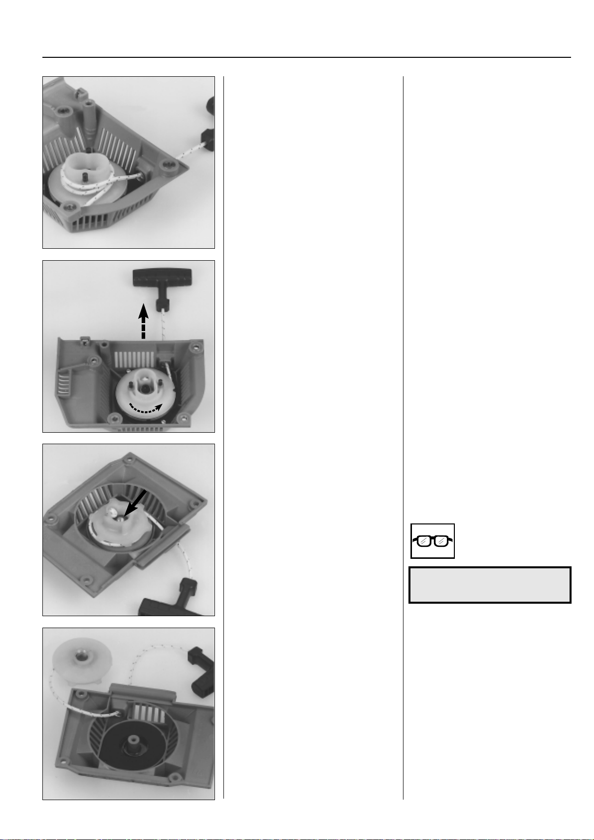
Tension the return spring. To tension the return spring.
Wind the cord 2 turns anticlockwise
around the hub on the starter pulley and
pull out the starter handle until the cord is
extended.
Repeat the procedure once more.
Check the spring tension.
NOTE!
With the starter cord fully extended it
must still be possible to turn the starter
at least a further half turn.
pulley
1
+ 1/2 r
Models 240/245
Dismantling
Release the spring.
Remove the starter pulley.
Lift out the spring cassette. The spring cassette sits freely in the
Models 240/245
Dismantling
Release the spring tension as described
for model 265.
Remove the screw and washer and lift out
the starter pulley.
WARNING!
!
starter housing and can easily be lifted
out to be replaced.
Wear protective glasses.
www.mymowerparts.com
9
Page 11

For Husqvarna Parts Call 606-678-9623 or 606-561-4983
1
Starter
Assembly
Check the starter housing for wear and
damage.
Fit the spring cassette.
Anchor the starter cord in the starter
pulley and wind it approx. 4 turns clock-
wise onto the pulley.
Assembly
Check the cord guide in the housing. If it
is worn the starter housing must be replaced.
Lubricate the spring with a few drops of oil
and position the spring cassette in the
starter housing.
Tie a small knot on the cord and seal the
ends by melting the cord ends, e.g. with a
soldering iron.
Anchor the starter cord in the starter
pulley and wind it about 4 turns clock-
around the pulley .
wise
Fit the starter pulley in the starter housing.
Fit the starter handle on the cord. Fit the starter handle as described for
Lubricate the bearing spindle with a few
drops of oil and fit the starter pulley in the
starter housing.
Position the washer and tighten the screw.
model 265, but tie a double knot as the
cord is lighter.
10
www.mymowerparts.com
Page 12

For Husqvarna Parts Call 606-678-9623 or 606-561-4983
Max
Starter
Tension the return spring. To tension the return spring
Wind the cord 2 turns clockwise around
the hub on the starter pulley and pull out
the starter handle until the cord is fully
extended.
Repeat the procedure once more, but
only wind the cord 1 turn around the hub.
Check the spring tension. Check the spring tension.
NOTE!
With the starter cord fully extended it
must still be possible to turn the starter
pulley at least a further half turn.
1
+ 1/2 r
Models 225, 232, 235,
240
Dismantling
Release the spring tension and dismantle the starter pulley.
Remove the spring cassette. Remove the screw and lift out the spring
Models 225, 232, 235,
240
Dismantling
Release the spring tension as described
for model 265.
Remove the screw and washer and lift out
the starter pulley.
cassette from the starter housing.
www.mymowerparts.com
!
WARNING!
Wear protective glasses.
11
Page 13

For Husqvarna Parts Call 606-678-9623 or 606-561-4983
1
Starter
Assembly
Check the starter housing for wear and
damage.
Fit a new spring cassette if necessary.
Fit a new starter cord. Fit a new starter cord. Tie the smallest
Assembly
Check the cord entry.
If it is worn the starter housing must be
replaced.
Lubricate the return spring with a few
drops of oil and fit the cassette in the
starter housing.
NOTE!
The end of the spring should be 3–
4 mm from the spindle to help assembly of the starter pulley.
knot possible on the cord and melt the
ends to stop it from fraying.
Wind the cord about 3 turns anticlock-
on the starter pulley.
wise
Position the starter pulley in the starter
housing and fit the washer and screw.
Max
Fit the starter handle. Fit the starter handle as described for
model 265.
Tension the return spring by winding the
starter cord 2 turns anticlockwise around
the hub on the starter pulley.
Repeat the procedure once more, but
with the cord only wound once around the
hub.
Check the spring tension.
NOTE!
With the starter cord fully extended it
must still be possible to turn the starter
pulley at least a further half turn.
12
+ 1/2 r
www.mymowerparts.com
Page 14

For Husqvarna Parts Call 606-678-9623 or 606-561-4983
Starter
1
Models 322, 325
Dismantling
Remove the 3 bolts and lift off the starter.
NOTE!
Ensure the bushings (A) that guide the starter towards the fuel tank are not lost.
A
Offload the spring tension.
Remove the screw from the centre of the
starter pulley and lift off the starter pulley .
Offload the spring tension in the same
way as described for model 265.
Remove the screw in the centre of the
starter pulley. Carefully lift out the starter
pulley from the starter housing.
Assembly
Clean the component parts and assemble in the reverse order as set out for
dismantling.
Assemble the starter pulley.
Assemble a new starter cord.
NOTE!
A new starter cord can be fitted
without the need of dismantling the
starter!
WARNING!
!
The return spring lies tensioned in
the starter and can fly out and
cause personal injury with careless handling.
Assembly
Clean component parts before assembly.
Replace the return spring/starter pulley
and starter cord, if necessary.
NOTE!
The return spring and starter pulley
are supplied pre-assembled and are
fitted in the starter housing as a
single unit.
Exercise care when opening the
packaging so that the spring does
not fly out.
Lubricate the spindle with a little grease
and fit the starter pulley.
Position the washer and tighten the screw.
Assemble a new starter cord. Slid it into
the starter pulley’s slot as illustrated and
then out through the cord guide in the
starter housing.
Make sure the knot on the end of the cord
is as small as possible!
Wear protective glasses.
www.mymowerparts.com
13
Page 15

For Husqvarna Parts Call 606-678-9623 or 606-561-4983
1
Starter
Assembling the starter handle.
Tension the return spring
Check the spring tension.
Fit the starter on the engine body.
Do not forget the guide sleeves for the fuel
tank.
Assemble the starter handle in the same
way as described for model 265, but tie a
double knot as the cord is lighter.
Tension the return spring. Pull out the
starter cord fully and lift it out of the cutout in the starter pulley.
Now turn the starter pulley anticlock-
wise, 6 turns.
Check the spring tension. With the starter
cord fully extended it should still be possible to turn the starter pulley further,
least a half turn.
at
Replacing the drive dogs
Dismantle the drive body.
504 91 06-05
Remove the circlip and replace any damaged drive dogs or springs, if necessary .
Replacing the drive dogs
Fit the piston stop no 504 91 06-05 in the
spark plug hole and loosen the nuts holding the drive body.
Remove the circlip holding the drive dog.
Lift out the drive dog and spring for re-
placement.
Assemble in the reverse order as set out
for dismantling.
14
www.mymowerparts.com
Page 16

For Husqvarna Parts Call 606-678-9623 or 606-561-4983
Starter
Model 122
2
1
Dismantling
Remove the covers from the muffler and
cylinder.
Dismantle the starter from the engine
body.
Model 122
Dismantling
Y ou must first remove the covers over the
muffler and cylinder to be able to dismantle the starter.
Remove the screw (1), pull out the lower
edge of the cover and lift it off.
Remove the screw (2) and lift off the
cylinder cover.
Remove the screws and lift off the starter
from the engine body.
1
Remove the starter hub from the crankshaft.
Replace the drive dog if it is damaged or
worn.
Unscrew the hub from the crankshaft.
Use a hammer and punch to loosen the
hub if necessary.
NOTE!
The nut is brazed on the drive.
The drive dog and its spring can easily be
replaced if damaged or worn.
Squeeze together the drive dog's axle
stud with pliers when dismantling.
www.mymowerparts.com
15
Page 17

For Husqvarna Parts Call 606-678-9623 or 606-561-4983
1
Starter
Release the spring tension and dismantle starter pulley.
Assembly
Fit a new return spring in the starter unit.
Release the spring tension as described
for model 265.
Remove the screw and washer and carefully lift out the starter pulley so that the
return spring does not fly out.
WARNING!
!
Assembly
Fit a new return spring in the starter unit.
Press the spring down correctly on the
fastener and lubricate with a few drops of
oil or cold resistant grease.
Ensure the ends of the spring are 2-3 mm
from the spindle.
Wear protective glasses.
Fit a new starter cord and position the
starter pulley in the starter housing.
Fit the starter handle.
Tension the return spring.
WARNING!
!
Fit a new starter cord. Tie the smallest
knot possible on the cord but leave free
an end of approx. 10 mm.
Press the free end into the cut-out in the
pulley hub reinforcement.
Wind the cord about 4 turns clockwise
(seen from the rear) on to starter pulley.
Position the starter pulley in the starter
housing and fit the washer and screw.
Fit the starter handle as described for
model 265, but tie a double knot on the
cord.
Lift up the starter cord from the cut-out
and wind it 2 turns
the hub on the starter pulley . Pull out the
starter handle until the cord is fully extended.
Repeat the procedure once again.
Wear protective glasses.
anticlockwise
around
16
www.mymowerparts.com
Page 18

For Husqvarna Parts Call 606-678-9623 or 606-561-4983
+ 1/2 r
Max
Starter
Check the spring tension.
Models 32, Mondo,
Mondo Mega
Dismantling
Remove the screws that hold the throttle
trigger.
1
NOTE!
With the starter cord fully extended it
must still be possible to turn the starter
pulley at least a further half turn.
Fit the hub, starter and covers in the
reverse order set out for dismantling.
Models 32, Mondo,
Mondo Mega
Dismantling
Remove the screws that hold the throttle
trigger and slide it along the shaft as far as
the throttle cable and electrical cables will
allow.
Lift out the throttle cable. Move the throttle trigger forward and lift
the throttle cable out of the trigger.
Disconnect the electrical cables.
Remove the shaft complete with handles.
Disconnect the electrical cables by the
engine body and remove the 4 screws
(models Mondo and Mondo Mega have 3
screws) that hold the shaft and handle on
the starter housing.
Lift off the shaft.
www.mymowerparts.com
17
Page 19

For Husqvarna Parts Call 606-678-9623 or 606-561-4983
1
Starter
Dismantle the centrifugal clutch.
Dismantle the starter.
Undo the nuts holding the centrifugal
clutch and lift off the clutch and the large
washer.
Remove the 4 screws and lift off the
starter.
Model 32
Pull out the electrical cables from the
starter housing using flat nose pliers.
Model Mondo
Also dismantle the screw by the spark
plug.
Remove the two locking plates that hold
the starter pulley axially.
Release the spring tension. Release the spring tension.
Remove the two locking plates that hold
the starter pulley axially.
Pull out the starter cord about 30 cm and
place the cord in the cut-out on the edge
of the starter pulley.
18
www.mymowerparts.com
Page 20

For Husqvarna Parts Call 606-678-9623 or 606-561-4983
Starter
Let the starter pulley slowly rotate backwards.
Lift off the starter pulley.
Remove the return spring from the starter
housing.
1
Let the starter pulley slowly rotate backwards (anticlockwise) and then lift off the
pulley.
NOTE!
Stop the rotation using your thumb.
WARNING!
!
Exercise great care when removing the
starter spring.
The spring is tensioned inside a sheet
cassette, nevertheless it can still easily
fly out when dismantled.
Take care so that your
thumb is not injured by
the cord's fastening
screw.
Assembly
Insert a new spring cassette in position in
the starter housing.
Replace the starter cord and attach it as
shown in the diagram.
WARNING!
!
Assembly
Lubricate the return spring with a few
drops of oil and position the new spring
cassette in the starter housing.
If the spring, despite your being careful, has
flown out reposition it again in the cassette
with the end turned as shown in the picture.
!
Attach the new starter cord to the starter
pulley and wind it about 3 turns clock-
wise
Wear protective glasses.
WARNING!
Wear protective glasses.
around the pulley .
www.mymowerparts.com
19
Page 21

For Husqvarna Parts Call 606-678-9623 or 606-561-4983
1
Starter
Fit the starter pulley. Lubricate the pulley spindle with a few
drops of oil.
Ensure the end of the spring is about 2–
3 mm from the spindle and position the
starter pulley.
NOTE!
Do
not
tighten the locking plates
that hold the starter pulley axially.
Fit the starter handle.
Fit the starter handle as described for
model 265.
Tie a double knot as the cord is lighter
than on model 265.
Max
+1/2 r
Tension the return spring. Tension the return spring.
● Pull out the cord approx. 30 cm and
stop the starter pulley with your thumb.
● Lift the cord up from one of the cutouts on the starter pulley.
● Wind the cord 2 turns clockwise
around the hub on the starter pulley.
● Pull out the starter cord fully.
Repeat the spring tensioning and fit the
locking plates.
Repeat the spring tensioning once more.
Ensure the starter pulley can still be turned
at least a further half turn with the cord
fully extended.
Tighten the locking plates that hold the
starter pulley axially.
NOTE!
Model 32 has a thin spacer under
the plates.
20
www.mymowerparts.com
Page 22
For Husqvarna Parts Call 606-678-9623 or 606-561-4983
Starter
Model 18H
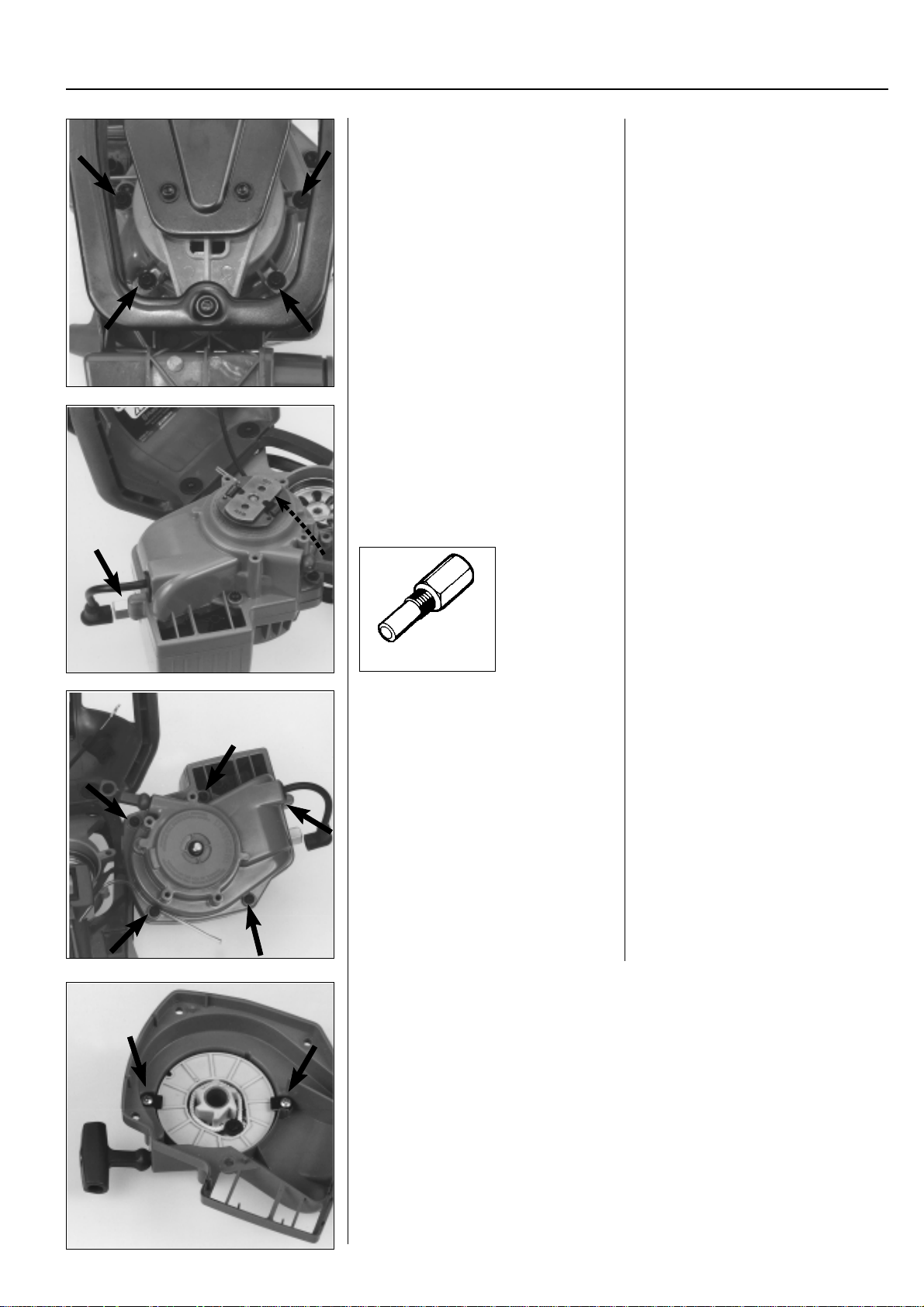
Dismantling
Dismantle the air filter, throttle cable and
carburettor.
Remove the 4 screws holding the engine
body and gear housing.
Dismantle the centrifugal clutch. Assemble the piston stop no. 504 91 06-
Model 18H
Dismantling
The starter is positioned between the
crankcase and the cutting equipment
drive.
First dismantle the spark plug, air filter,
throttle cable and carburettor.
Turn the mower upside down so that the
screws holding the engine body are accessible. Remove the 4 screws.
05 in the cylinder.
Unscrew the centrifugal clutch. First
loosen it using a hammer and punch,
anticlockwise.
1
504 91 06-06
Dismantle the starter from the engine. Dismantle the starter.
Remove the 5 screws holding the starter
housing
Lubricate the ignition cable with a few
drops of oil and remove the rubber grommet in the cover.
Lift off the starter housing.
The following procedures are the same as for models 32, Mondo:
Remove the locking plates holding the starter pulley axially.
Offload the spring tension.
Dismantle the starter pulley and spring cassette from the starter housing.
www.mymowerparts.com
21
Page 23

For Husqvarna Parts Call 606-678-9623 or 606-561-4983
1 Starter
Assembly (also see model Mondo)
Place a new spring cassette in position in the starter housing.
Replace the cord and attach as illustrated.
Assemble the starter pulley.
Assemble the starter handle (see model 265).
Tension the return spring.
Repeat tensioning the spring and fit the locking plates.
Models 140B, 141B
Dismantling
Remove the screws and lift off the starter.
Offload the spring tension and remove
the starter pulley from the starter housing.
Models 140B, 141B
Dismantling
Remove the 4 screws holding the starter
against the engine body.
Lift the starter cord out of the cut-out in
the starter pulley.
Offload the spring tension by allowing the
starter pulley to rotate backwards. Stop
the pulley using your thumb.
Remove the screw and washer from the
centre of the starter pulley.
22
Lift off the starter pulley.
Dismantle the return spring.
Clean and replace any damaged parts.
Carefully lift off the starter pulley and
return spring.
!
The return spring lies tensioned in the
starter housing and can fly out and cause
personal injury with careless handling.
Clean and replace any damaged parts.
www.mymowerparts.com
WARNING!
Wear protective glasses.
Page 24

For Husqvarna Parts Call 606-678-9623 or 606-561-4983
Starter
Assembly
Fit a new return spring in the starter
housing.
Replace the starter cord and attach as
illustrated.
Wind the cord 4 turns clockwise around
the starter pulley.
Lubricate the spindle and return spring
and assemble the starter pulley.
1
Assembly
Fit a new return spring in the starter
housing. Exercise great care so that it
does not fly out.
WARNING!
!
Check that the spring’s mounting is facing the right way!
Attach a new starter cord in the starter
pulley as illustrated.
Wind the cord 4 turns clockwise around
the starter pulley.
Lubricate the spindle and return spring
with a few drops of oil.
Place the starter pulley in position and
tighten the screw in the centre. Do not
forget the washer.
Wear protective glasses.
Assemble the starter handle. Assemble the starter handle.
The collar on the washer should face
towards the starter handle.
Tension the return spring.
Check that the pulley can be turned a
further half turn with the starter cord fully
extended!
Tension the return spring.
● Pull out the cord approx. 30 cm and
stop the starter pulley using your
thumb.
● Lift the starter cord up in the cut-out in
the starter pulley.
● Wind the cord 2 turns anticlockwise
around the hub on the starter pulley.
● Pull out the starter cord fully.
www.mymowerparts.com
23
Page 25
For Husqvarna Parts Call 606-678-9623 or 606-561-4983
1 Starter
Models 140B, 141B
Drive dogs
Dismantle the drive from the crankshaft.
Replace the drive dogs if they are dam-
aged or worn.
Assembly, general
Assemble the starter following the reverse order set out for dismantling.
503 21 22-01
Models 140B, 141B
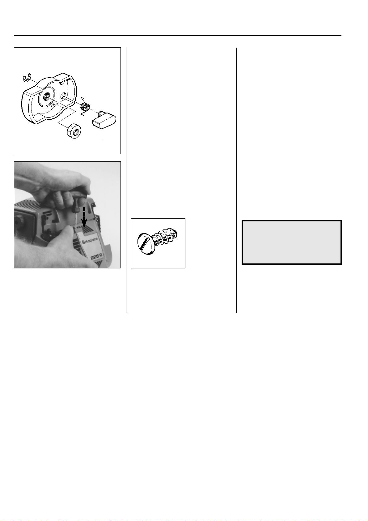
Drive dogs
Dismantle the drive dog from the crankshaft.
Unscrew the nut (anticlockwise) and then
unscrew the drive in the same direction.
Replace the drive dogs if they are damaged or worn.
Fit the new dog in the hole marked “R”.
Assembly, general
Assemble the starter.
Pull out the starter cord a little. Position
the starter. Release the starter cord and
ensure that the drive dogs grip in the
starter pulley.
Tighten the screws.
NOTE!
If the plastic threads in the crankcase have, for some reason,
been damaged it is recommended to use an over dimensioned screw (no 503 21 22-01).
Replacing the drive
dogs
See chapter 2. “Ignition system, flywheel”
with regard to engines that have the drive
dogs fitted on the flywheel.
Replacing the drive
dogs
See chapter 2. “Ignition system, flywheel”
with regard to engines that have the drive
dogs fitted on the flywheel.
24
www.mymowerparts.com
Page 26

For Husqvarna Parts Call 606-678-9623 or 606-561-4983
Ignition system
2.
Contents
Checking the spark________________________ 26
Replacing the spark plug cap ________________ 28
Dismantling ______________________________ 29
Dismantling the flywheel____________________ 33
Drive dogs_______________________________ 34
Assembly _______________________________ 36
Technical data ____________________________ 38
www.mymowerparts.com
25
Page 27

For Husqvarna Parts Call 606-678-9623 or 606-561-4983
2
Ignition system
The engine is equipped with an electronic ignition
system with no moving parts. Consequently, a faulty
component cannot be repaired, but must be replaced
with a new one.
Checking the spark
All models
Clean the electrodes and check the electrode gap.
The ignition spark in an electronic ignition system has a very short burn time and can be
judged to be weak and is at times difficult to see
when trouble shooting.
Checking the spark
All models
Remove the spark plug and clean off any
carbon deposits using a wire brush.
Check the electrode gap, it should be 0.5
mm.
Adjust the gap to the correct size using
the side electrode.
If the electrodes are worn by more than
50% the spark plug should be replaced.
Check whether there is a spark when
attempting to start, if not test using spark
plug no. 502 71 13-01.
If the electrodes are worn by more than
50% the spark plug should be replaced.
An excessive spark gap can overload the
ignition module and risk short circuiting.
Ensure the stop switch is in the 'start'
position.
Earth the spark plug against the cylinder
and pull the starter handle sharply.
There should now be a spark between the
electrodes.
If there is no spark try using the test spark
plug no. 502 71 13-01.
If there is spark now the spark plug is
faulty.
Fit a new spark plug.
26
502 71 13-01
www.mymowerparts.com
Page 28

For Husqvarna Parts Call 606-678-9623 or 606-561-4983
Ignition system
Fit a new spark plug.
If there is no spark disconnect the stop
switch.
Replace the switch if necessary.
Check the ignition lead's connections. Still no spark?
A
Fit a new spark plug.
If the procedure does not produce a spark
remove the short circuit cable from either
the ignition module or the stop switch.
If there is now a spark the stop switch is
faulty.
Replace the switch.
Check the spark plug connections.
Pull back the rubber covers by the spark
plug (A) and the ignition module (B) and
check that the ignition cable is not damaged. Cut off a piece of the cable to give
a good connection if required.
2
B
Lubricate the cable ends with grease. Lubricate the cable ends with a little
grease to facilitate assembly and to prevent dampness from entering the connections.
Check other cables and connections. Still no spark?
Check other cables and connections for
bad contact (dirt corrosion, cable breaks
and damaged insulation).
www.mymowerparts.com
Tip!
Use an ohmmeter to check whether there
is a broken cable caused by crushing, for
example.
27
Page 29

For Husqvarna Parts Call 606-678-9623 or 606-561-4983
2
Ignition system
Check the air gap. Still no spark?
Check the air gap between the flywheel's
magnet and the ignition module. The gap
should be 0.3 mm.
Use air gap gauge 502 51 34-02.
Model 122 should have a 0.38 mm gap.
Use air gap gauge 531 00 48-61
502 51 34-02
Adjust the air gap.
531 00 48-61
Adjust the air gap to the right measurement.
● Loosen the screws.
● Insert the gauge and press the igni-
tion module against the flywheel.
● Tighten the screws and check the air
gap once again.
If there is still no spark the ignition system
should be replaced.
Model 122
Changing the spark plug
cover
1. Push the ignition cable through the
spark plug cover.
2. Make a hole in the ignition cable for
the contact spiral.
502 50 06-01
3. Fit the contact spiral on the ignition
cable.
Changing the spark plug
cover
1. Lubricate the ignition cable using a
little grease and push it through the
spark plug cover.
2. Cut off a piece of the ignition cable
(about 5 mm) and make a hole in the
cable for the contact spiral using the
pliers no. 502 50 06-01.
3. Fit the contact spiral on the ignition
cable, taking care to form the wire
along the cable.
4. Pull the contact spiral into the spark
plug cover.
NOTE!
It is important that the point of the
contact spiral is positioned so that
it's unable to pierce the spark plug
cover.
28
www.mymowerparts.com
Page 30

For Husqvarna Parts Call 606-678-9623 or 606-561-4983
Ignition system
Dismantling
General
Remove all components necessary to
gain access to the flywheel and ignition
module.
Models 322, 325
Dismantle the guard over the muffler.
Disconnect the throttle cable and remove
the screws holding the clutch cover.
Remove the clutch cover and loosen the
short-circuit cable from the ignition module.
2
Dismantling
General
Dismantle the cylinder cover, spark plug,
starter and air guide rail.
Models 322, 325
In addition to the components mentioned
above, you also need to dismantle the
guard over the muffler.
Disconnect the throttle cable from the
carburettor.
Remove the three screws holding the
clutch cover.
Remove the clutch cover complete with
the shaft from the engine.
Loosen both ends of the short-circuit cable from the ignition module.
504 90 00-02
B
A
B
A
B
Dismantle the ignition module and the
centrifugal clutch.
504 90 00-03
Model 122
Pull apart the connectors (A).
Remove the throttle cable at (B).
Remove the screws (C) and lift off the
shaft.
Remove the remaining screws (A) holding the ignition module and both screws
(B) that hold the centrifugal clutch.
Lift off the clutch and ignition module.
Model 122
Pull apart the connector on the electrical
cables (A) and remove the throttle cable
from the carburettor lever (B).
Remove the screws (C) and lift off the
shaft.
C
29
www.mymowerparts.com
Page 31
For Husqvarna Parts Call 606-678-9623 or 606-561-4983
2
Ignition system
Models 32, Mondo
Remove the starter.
Dismantle the fan cover and the centrifugal clutch.
531 00 48-62
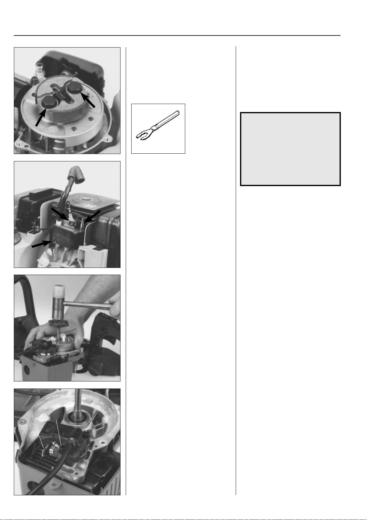
Dismantle the ignition module and loosen
other cable connections.
Models 32, Mondo
Remove the starter. See chap. 1 “Starter .”
Remove the screws and lift off the fan
cover.
Dismantle the centrifugal clutch by loosening the two bolts.
NOTE!
Hold the clutch carefully using a
pipe grip so that the soft clutch
linings are not damaged.
We recommend the use of tool no.
531 00 48-62.
Notice which way the clutch faces.
The “L”-markings on the clutch
shoes face outwards.
Dismantle the ignition module by unscrewing the two bolts.
Loosen the other cable connections and
lift out the ignition module.
Model 18H
Remove the spacer and washer and screw
the clutch down on the crankshaft.
Hold the flywheel and sharply tap the
clutch a few times until the flywheel releases.
Dismantle the ignition module. Dismantle the ignition module.
B
B
A
Model 18H
Remove the long spacer and washer from
the crankshaft.
Screw down the clutch a few turns on the
shaft.
Hold the flywheel and sharply tap the
clutch a few times until the flywheel releases.
Remove the short-circuit cable (A) and
both screws (B).
30
www.mymowerparts.com
Page 32
For Husqvarna Parts Call 606-678-9623 or 606-561-4983
Ignition system
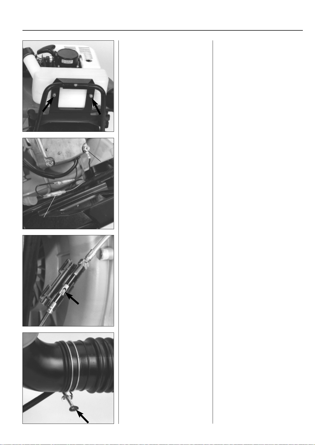
Models 140B, 141B
Dismantle the fuel tank.
Pull apart the short-circuit cable connector and remove the earth cable.
B
Models 140B, 141B
Empty the fuel tank and pull off the fuel
hoses from the carburettor.
Note how the hoses are connected.
Remove the screws and lift off the fuel
tank.
Separate the connectors for the shortcircuit cable (A) and remove the earth
cable (B) by removing the crankcase
screw.
2
A
Fold open the protective sleeve and separate the throttle cable.
Remove the blower pipe. Loosen the hose clip and remove the
Open the protective sleeve over the cable
joint and lift out the throttle cable running
to the throttle.
blower pipe.
www.mymowerparts.com
31
Page 33
For Husqvarna Parts Call 606-678-9623 or 606-561-4983
2
Ignition system
B
A
A
A
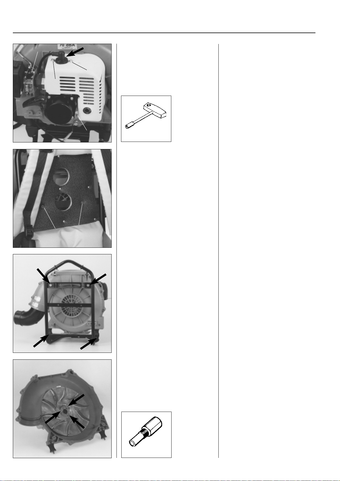
Dismantle the cylinder cover, heat guard
around the cylinder and the rotary valve
from the carburettor.
502 50 22-01
Dismantle the harness. Remove the harness from the tubular
Lift off the spark plug cap and unscrew
the spark plug.
Remove the 3 screws (A) holding the
cylinder cover and remove this and the
heat guard from around the cylinder.
Dismantle the rotary valve (B) from the
carburettor by removing the 2 screws
holding the cover. Let the throttle hang
from the throttle cable.
frame by removing both screws (A).
A
A
Remove the pipe bend.
Remove all screws and separate both
halves of the fan housing.
Dismantle the impeller. Screw in the piston stop no. 504 91 06-5
Remove the pipe bend.
Remove the cleaning cover and all the
screws (12) holding both halves of the fan
housing.
Separate the halves.
in the spark plug hole and remove the 3
screws holding the impeller using tool no.
502 50 23-01.
32
504 91 06-05
www.mymowerparts.com
Page 34
For Husqvarna Parts Call 606-678-9623 or 606-561-4983
Ignition system
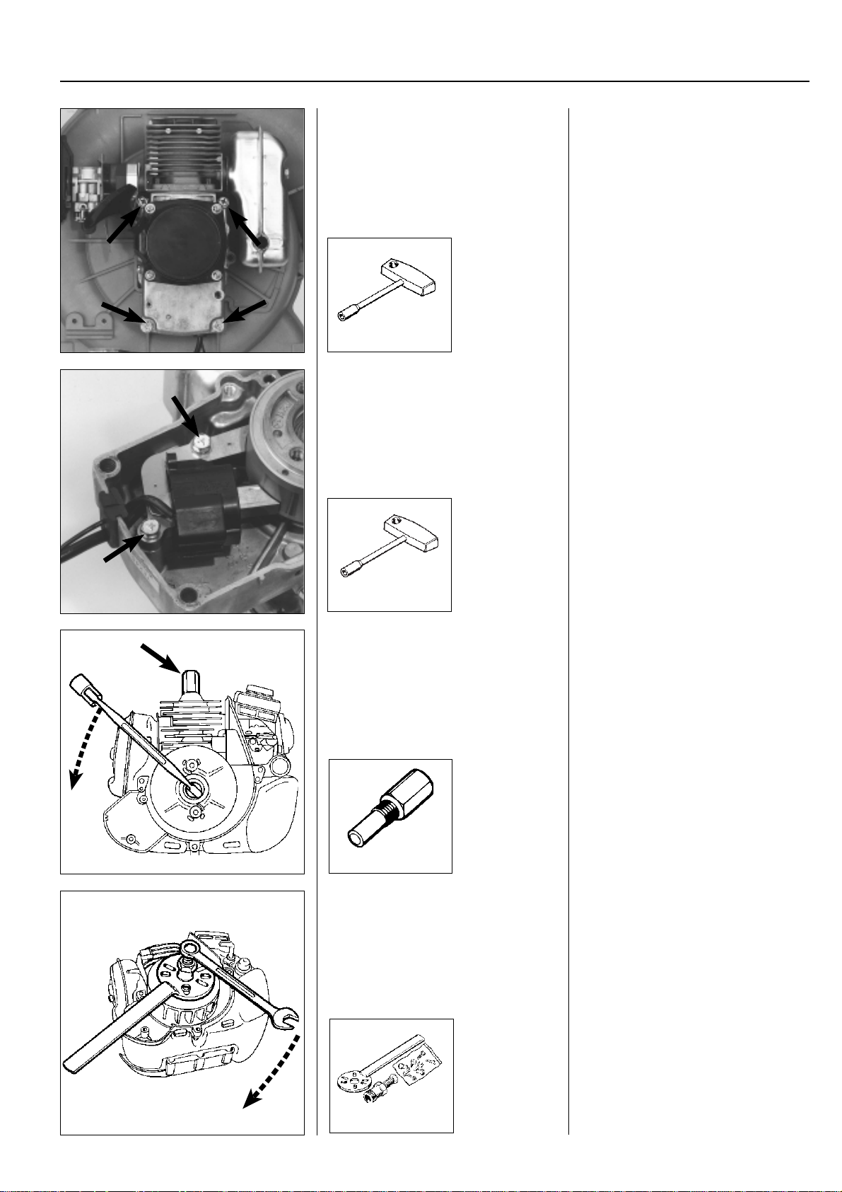
Dismantle the engine from the fan housing.
502 50 23-01
Remove the screws and lift off the ignition
module.
2
Remove the 4 screws holding the engine
against the fan housing.
Lift off the engine.
Remove the screws and lift off the ignition
module with the ignition lead, short-circuit cable and grommet.
502 50 22-01
Dismantling the
flywheel
Fit the piston stop no. 504 91 06-05 and
remove the nut holding the flywheel and
where appropriate the plate with drive
dogs.
504 91 06-05
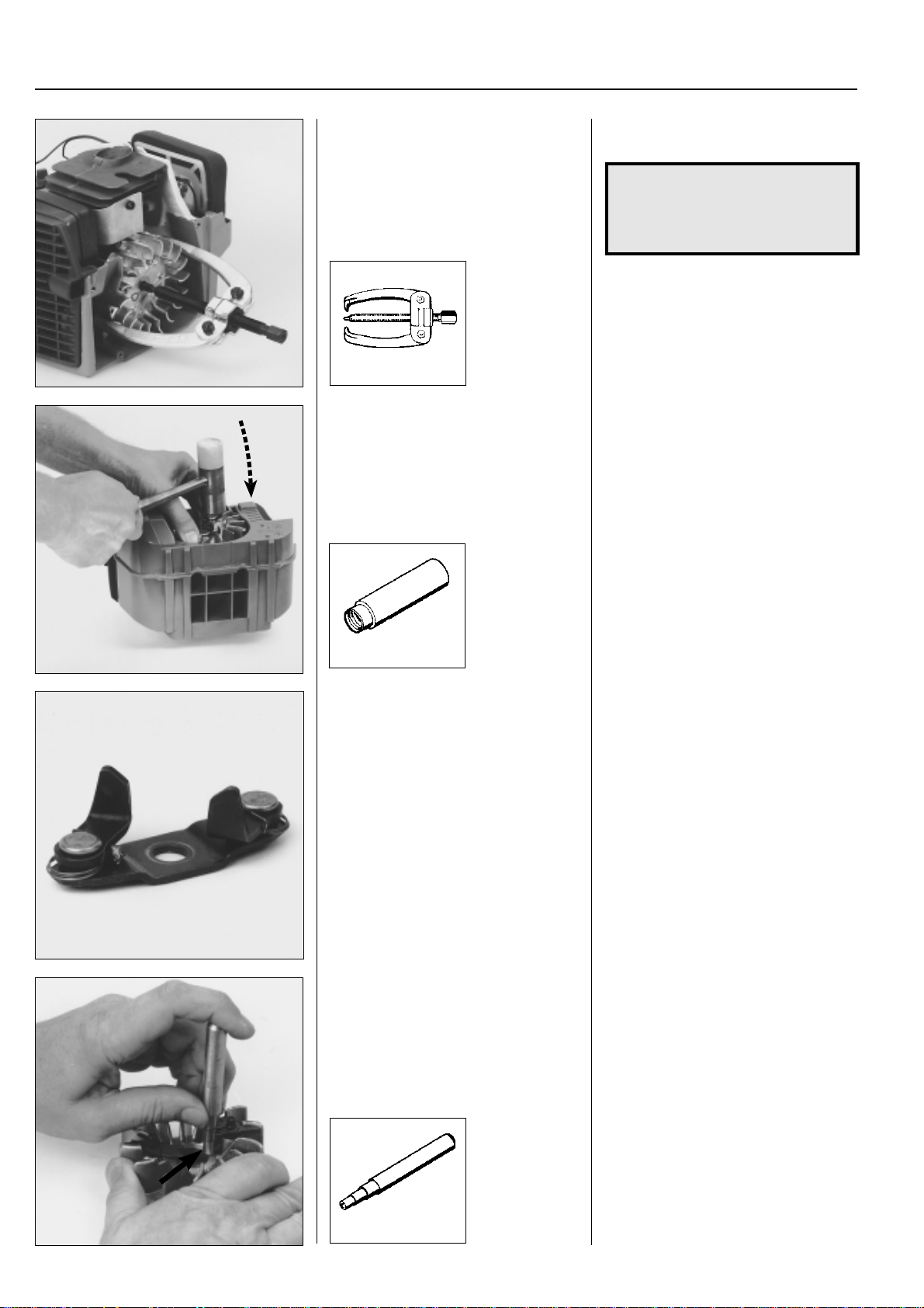
Dismantle the flywheel by using the flywheel puller.
Dismantling the
flywheel
Assemble the piston stop no. 504 91 0605 in the spark plug hole.
Ensure the piston stop is screwed down
to the bottom.
Remove the nut holding the flywheel and
where appropriate the plate with drive
dogs.
NOTE!
The piston stop cannot be used on model
122.
Dismantle the flywheel from the crankcase using the puller no. 502 51 49-01.
Gently knock the puller screw with a hammer, if the flywheel sits tightly on the
crankshaft.
Select suitable screws and align the puller
so that it does not pull at an angle.
502 51 49-01
www.mymowerparts.com
33
Page 35
For Husqvarna Parts Call 606-678-9623 or 606-561-4983
2
Ignition system
Dismantle the flywheel by using the bearing puller.
504 90 90-01
Dismantle the flywheel by using a hammer and push bar.
502 51 94-01
Pull off the flywheel using the bearing
puller no. 504 90 90-01.
NOTE!
The arms on the puller should be
placed by and opposite the magnet on
the flywheel to avoid damaging it.
Is the flywheel really tight?
Lift up the engine body by holding the
puller and knock the puller screw a few
times with a hammer.
Screw the nut on the axle to protect the
thread.
Unhook the springs and fold back the
drive dogs to give a little room for the
hammer.
Grip the flywheel and lift up the engine
body.
Apply a few sharp blows with a hammer
on the flywheel nut until the flywheel frees
itself from the axel.
Tip!
Use the push bar to protect the tread at
the same time as it is easier to use the
hammer.
Do not screw the push bar completely up
to the flywheel – leave about 2 mm.
Drive dogs
General
Check the drive dogs with regard to wear
and cracking.
Replace damaged components.
Dismantle the locking clip. Turn the locking clip so that the opening
Drive dogs
General
Check the drive dogs with regard to wear
and cracking.
Replace damaged components.
The entire unit must replaced if the drive
dogs are fitted on a separate bridge.
aligns with the centre of the flywheel.
Use, e.g. punch no. 505 38 17-05 and
press off the clip.
34
505 38 17-05
www.mymowerparts.com
Page 36
For Husqvarna Parts Call 606-678-9623 or 606-561-4983
Ignition system
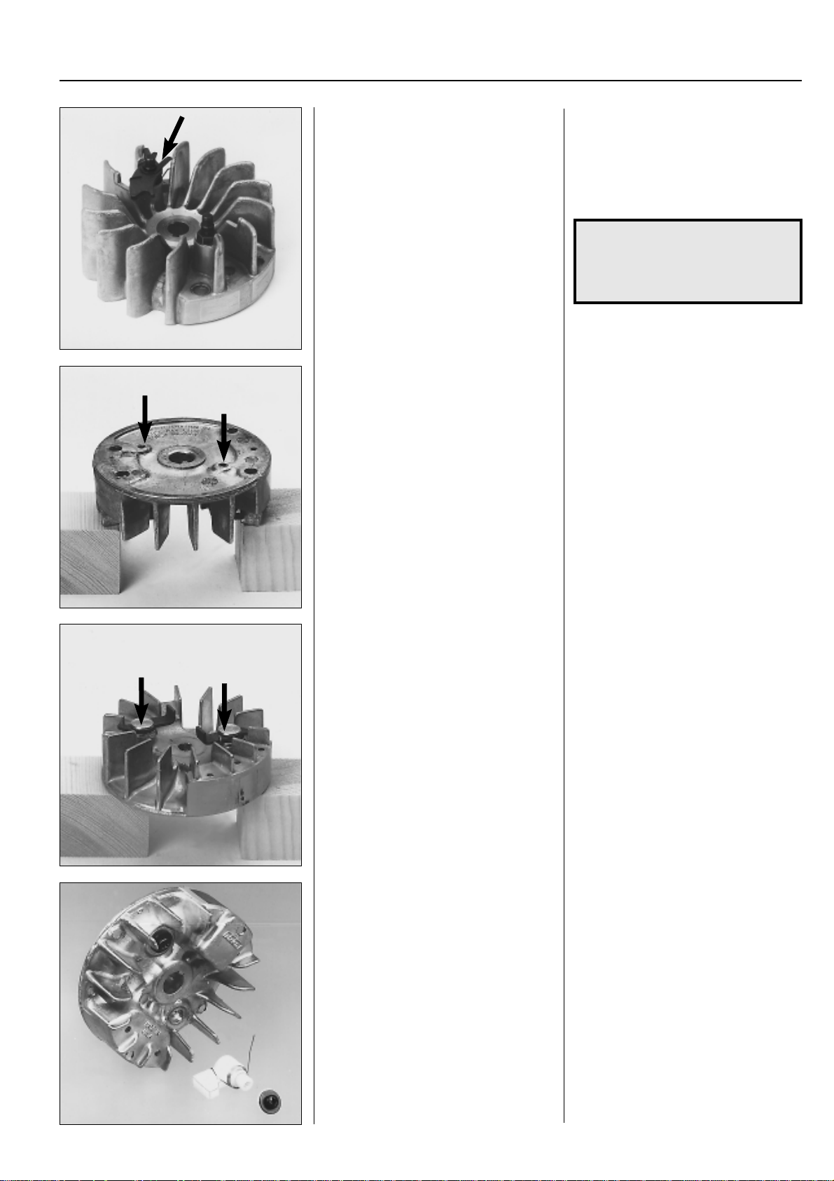
Dismantle the drive dogs and the return
spring.
Unscrew the bearing pin.
Replace any damaged parts.
Press out the bearing studs using a suitable punch.
2
Dismantle the drive dogs and the return
spring.
Unscrew the bearing pin.
Replace any damaged parts.
Check that the drive dogs move easily .
NOTE!
The spring clip's opening should
be turned outwards between the
fan fins.
Replace the drive dogs and springs as
follows if they are journalled on a stud
pressed into the flywheel:
Place the flywheel on support blocks and
press out the studs using a suitable punch.
Replace damaged parts.
Models Mondo, 18H
The drive dogs can be dismantled once
the screws on the opposite side of the
flywheel have been removed.
Replace damaged parts.
Ensure the springs are not crushed when
the stud is pressed into the flywheel.
Check that the drive dogs move easily .
Models Mondo, 18H
On these models the drive dogs are held
in place by screws, tightened from the
opposite side of the flywheel.
Dismantle the bolts and lift off the drive
dogs.
www.mymowerparts.com
35
Page 37
For Husqvarna Parts Call 606-678-9623 or 606-561-4983
2
Ignition system
Assembly
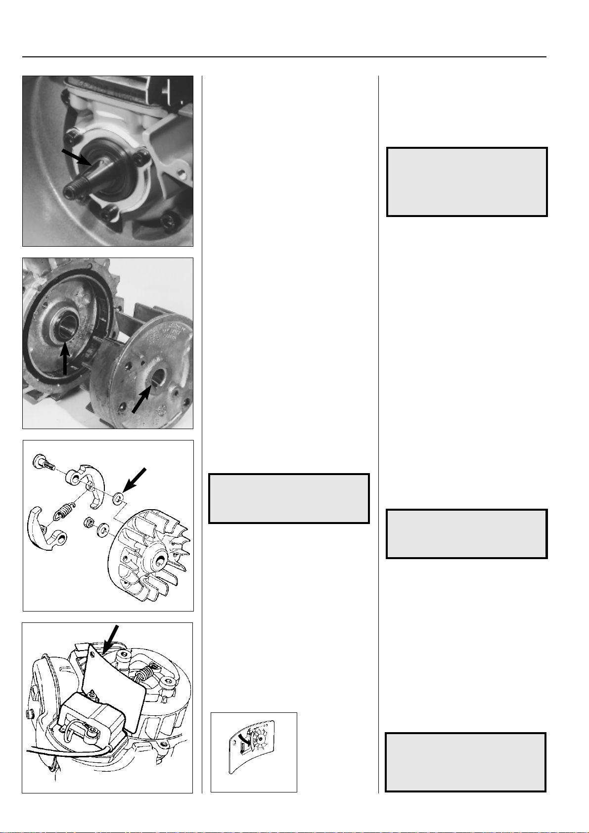
Check that the keyway and key on the
crankshaft are not damaged.
Check that the keyway and cast key on
the flywheel are not damaged.
Fit the flywheel.
Assembly
Check that the keyway and key on the
crankshaft are not damaged.
Fit a new key if necessary and ensure it
sits correctly in the keyway.
NOTE!
If the crankshaft has two keyways
it is the keyway that is open all the
way out to the thread which is
used if the flywheel has a cast key .
Check that the keyway and cast key on
the flywheel are not damaged.
Fit the flywheel on the crankshaft and
check that key and keyway are correctly
aligned before the flywheel nut is tightened.
Tighten the nut to a torque of 25–35 Nm.
Models 322, 325
Assemble the centrifugal clutch.
NOTE!
Do not forget the washers between
the flywheel and centrifugal clutch.
Assemble the ignition module and adjust
the air gap to 0.3 mm.
Models 322, 325
If the crankshaft has two keyways, the
flywheel should be fitted in the right-hand
keyway seen from the axle end.
Assemble the centrifugal clutch.
NOTE!
Do not forget the washers between
the flywheel and centrifugal clutch.
Assemble the ignition module.
Wait to connect the short-circuit cable to
facilitate the adjustment of the air gap. It
should be 0.3 mm between the permanent magnets in the flywheel and the
ignition module.
Now fit the short-circuit cable and the
remaining parts in the reverse order as
set out for dismantling.
36
NOTE!
Do not forget the rubber bush-
ings between the clutch cover and
502 51 34-02
the fuel tank.
www.mymowerparts.com
Page 38
For Husqvarna Parts Call 606-678-9623 or 606-561-4983
Ignition system
Model 122
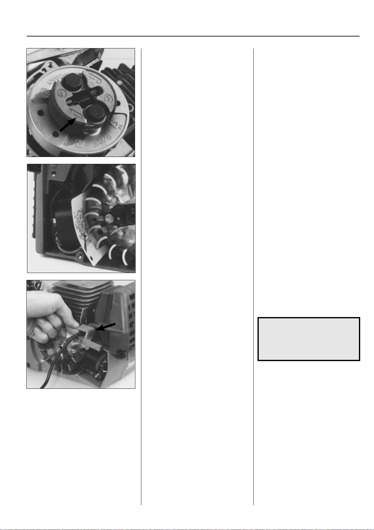
Turn the centrifugal clutch so that the “L”marking on the clutch shoes is facing
outwards.
All models
Fit the ignition module.
Adjust the air gap (0.3 mm).
Fit the other cables.
Fit the remaining components in the re-
verse order set out for dismantling.
2
Model 122
As the centrifugal clutch is fitted on the
flywheel it is important that it is positioned
so that the “L-marking” on the shoes faces
outwards.
“L” means left rotation.
All models
Fit the ignition module.
Adjust the air gap (0.3 mm).
Also see page 26.
Fit the other cables and ensure they sit
correctly in the cable channels, etc. so
that they cannot be damaged.
Fit the remaining components in the reverse order set out for dismantling.
Model 250
Do not forget to fit the heat guard for the
ignition cable.
Model 250
Fit the earth cable using the AMP connector on the ignition module before it is
screwed onto the crankcase.
NOTE!
Do not forget the plastic compo-
nents that protect the ignition cable from the radiant heat from the
muffler.
www.mymowerparts.com
37
Page 39

For Husqvarna Parts Call 606-678-9623 or 606-561-4983
2
Ignition system
Technical data
Model Spark plug Electrode gap Ignition Air gap
mm/inch system mm/inch
Mondo Champion RCJ8Y 0.5/0.02 Phelon 0.3/0.012
NGK BPM 6A CD
122L NGK BPM 6Y 0.6/0.024 Ikeda Denso 0.3/0.012
Solid State
Mondo Max Champion 0.5/0.02 Phelon 0.3/0.012
RCJ 8Y CD
225L/LD Champion 0.5/0.02 Walbro 0.3/0.012
RCJ 7Y CD
232L Champion 0.5/0.02 Walbro 0.3/0.012
RCJ 7Y CD
Mondo Mega Champion 0.5/0.02 Phelon 0.3/0.012
RCJ 8Y CD
225R/RD Champion 0.5/0.02 Walbro 0.3/0.012
RCJ 7Y CD
232R Champion 0.5/0.02 Walbro 0.3/0.012
RCJ 7Y CD
322 Champion 0.5/0.02 Walbro 0.3/0.012
RCJ 7Y CD
325 Champion 0.5/0.02 Walbro 0.3/0.012
RCJ 7Y CD
235R Champion 0.5/0.02 Walbro 0.3/0.012
RCJ 7Y CD
240R Champion 0.5/0.02 Electrolux 0.3/0.012
RCJ 7Y ET
245R Champion 0.5/0.02 Electrolux 0.3/0.012
RCJ 7Y ET
250R Champion 0,5/0.02 Electrolux 0.3/0.012
RCJ 7Y ET
245RX Champion 0.5/0.02 Electrolux 0.3/0.012
RCJ 7Y ET
250RX Champion 0.5/0.02 Electrolux 0.3/0.012
RCJ 7Y ET
252RX Champion 0.5/0.02 Electrolux 0.3/0.012
RCJ 7Y ET
265RX Champion 0.5/0.02 SEM 0.3/0.012
RCJ 7Y GA6 CD
240RBD Champion 0.5/0.02 Walbro 0.3/0.012
RCJ 7Y CD
235P Champion 0.5/0.02 Walbro 0.3/0.012
RCJ 7Y CD
250PS Champion 0.5/0.02 Electrolux 0.3/0.012
RCJ 7Y ET
225E Champion 0.5/0.02 Walbro 0.3/0.12
RCJ 7Y CD
18H Champion 0.5/0.02 Phelon 0.3/0.012
RCJ 8Y Solid State
225H60/75 Champion 0.5/0.02 Walbro 0.3/0.012
RCJ 7Y CD
140B/141B NGK 0.6–0.7/ Kawasaki 0.4/0.016
BPM 7A 0.024–0.028 Transistor
132HBV Champion 0.6/0.024 Phelon 0.25–0.35/
CJ 8Y CD 0.010–0.014
225BV/225HBV Champion 0.5/0.02 Walbro 0.3/0.012
RCJ 7Y CD
38
www.mymowerparts.com
Page 40
For Husqvarna Parts Call 606-678-9623 or 606-561-4983
Fuel system
3.
Contents
Air filter __________________________________ 4 0
Tank venting ______________________________ 41
Fuel filter _________________________________ 43
Primer pump ______________________________ 4 4
Carburettor design _________________________ 48
Carburettor settings ________________________ 63
CARB-designed carburettor __________________ 65
Throttle __________________________________ 68
Throttle cable _____________________________ 71
Technical data _____________________________ 79
www.mymowerparts.com
39
Page 41
For Husqvarna Parts Call 606-678-9623 or 606-561-4983
3
The fuel system comprises, in addition to the fuel
tank and the carburettor, the air filter, fuel filter and
tank venting.
All these components interact so that the engine
receives the optimum mixture of fuel and to make it
as efficient as possible. Extremely small adjust-
Fuel system
Air filter
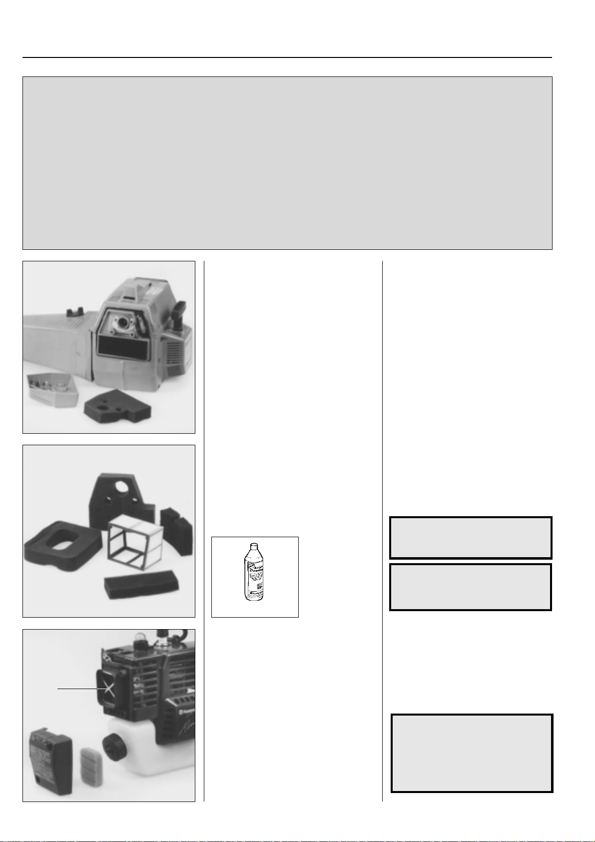
Dismantle the cylinder cover and air filter
cover so that the filter is accessible.
ments to the carburettor setting or air filter blockage have a great effect on how the engine runs
and its efficiency.
The carburettor on our models can come from
several manufacturers, but the operation and
repair techniques are essentially the same.
Air filter
Dismantle the cylinder cover and air filter
cover so that the filter is accessible.
The air filter material can either be of
foam or of fine mesh nylon weave.
Both types are cleaned in tepid, soapy
water.
Damaged filters shall be replaced with a
new filter.
505 69 85-70
Model Mondo
A
Dismantle the air filter cover and lift out
the air filter for cleaning.
The air filter material can either be of
foam or of fine mesh nylon weave.
Both types are cleaned in tepid, soapy
water.
Damaged filters shall be replaced with a
new filter.
WARNING!
!
NOTE!
The filter must be dry when its refit-
ted.
Tip!
Use Husqvarna's cleaning agent Active
Cleaning no. 505 69 85-70.
Model Mondo
Dismantle the air filter cover and lift out
the air filter for cleaning.
NOTE!
It is important when refitting that
the filter support (A) is not
forgotten. Otherwise particles
from the air filter can be drawn
into the carburettor.
Do not clean the filter in
petrol. Hazardous!
40
www.mymowerparts.com
Page 42
For Husqvarna Parts Call 606-678-9623 or 606-561-4983
Fuel system
A
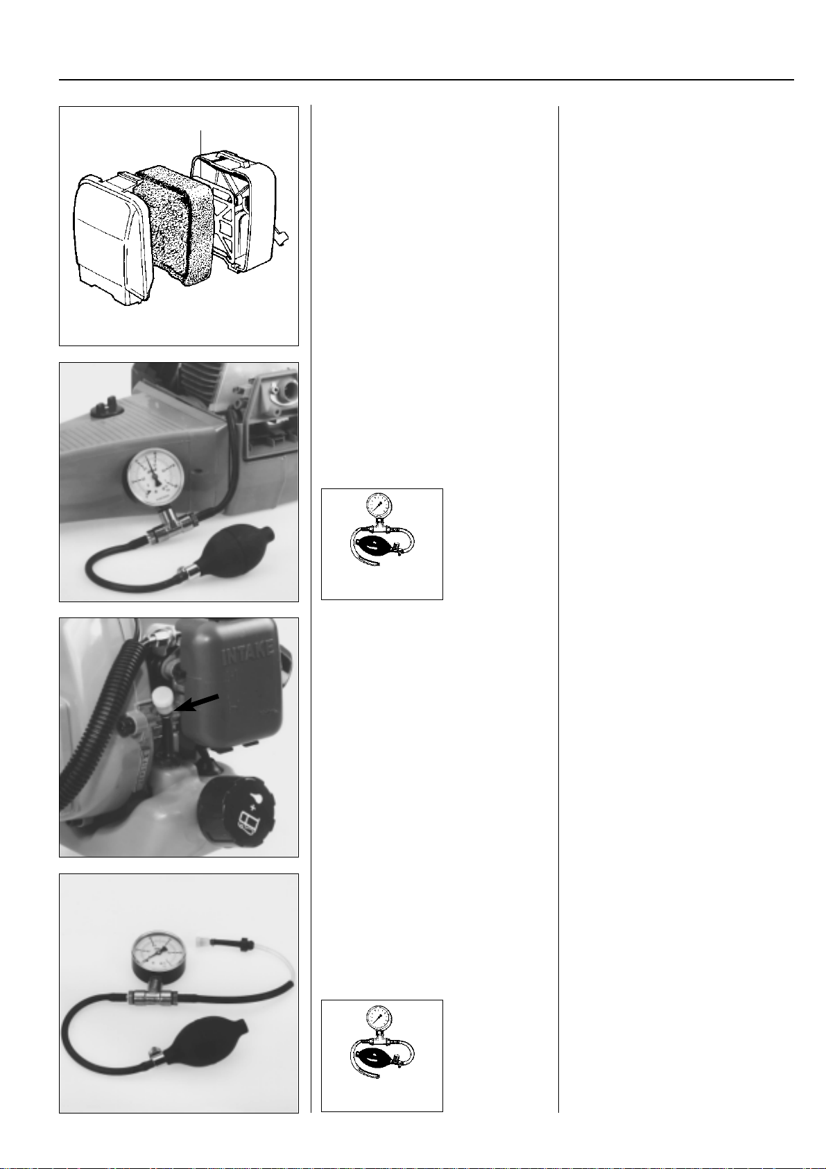
Model 141B
Remove the air filter cover and lift out the
air filter for cleaning.
Tank venting
Check that the tank venting valve functions.
Change the tank cap on most models if
the valve is faulty .
502 50 37-01
502 50 38-01
Model 141B
Press down the catch on the cover over
the air filter housing and remove the cover
and the air filter for cleaning.
Clean the filter in the same way as described above.
Fit the filter with the smooth side facing in
towards the carburettor.
Ensure the support grille (A) is in position.
Tank venting
On most models the tank venting is located in the fuel cap. It is important for the
operation of the engine that it works.
●
Remove the fuel pipe from the carburettor and empty the fuel from the tank.
●
Connect the fuel pipe to the pressure
tester no. 502 50 38-01 resp. vacuum
tester no. 502 50 37-01.
●
Pump a pressure resp. underpressure
of 50 kPa (0.5 bar) in the tank.
●
The pressure should drop to 20 kPa
(0.2 bar) resp. return to normal pressure within 45 seconds.
3
Model 122
Dismantle the valve complete with hose
by pulling it upwards.
Pressure test the valve using pressure
and vacuum.
Model 122
The valve is located on this model by the
carburettor and can easily be dismantled
from the tank for inspection. If necessary
pull it up with the help of a screwdriver.
Pressure test the valve using pressure
and vacuum.
The valve should open at:
Pressure: 25–30 kPa (0.25–0.30 bar)
V acuum: 25–30 kPa (0.25–0.30 bar)
Replace the complete valve and hose if it
is faulty .
Apply a small amount of grease on the
hose connection to facilitate fitting the
valve in the tank.
502 50 37-01
502 50 38-01
www.mymowerparts.com
41
Page 43
For Husqvarna Parts Call 606-678-9623 or 606-561-4983
3
Fuel system
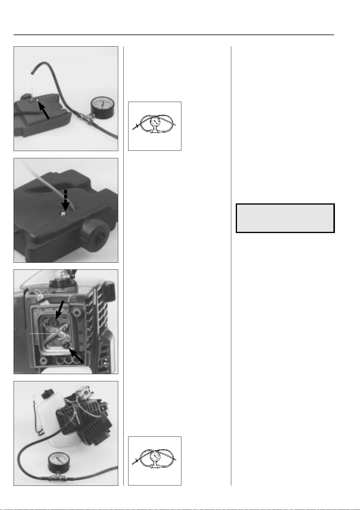
Model 32
The venting valve is located in the tank.
Check that it functions using the vacuum
tester 502 50 37-01.
502 50 37-01
Replace the valve if it does not open for
vacuum in the tank.
Model 32
The venting valve is inserted in the tank.
To gain access for inspection or replace-
ment it is necessary to dismantle the
cylinder cover and the starter.
Remove the fuel pipe from the carburettor
using a pair of flat pliers and connect the
pipe to the vacuum tester 502 50 37-01.
Lower the pressure to –50 kPa (0.5 bar).
The pressure should normally drop after
20 seconds.
If this is not the case the valve should be
replaced.
Press the down valve in the tank using a
suitable punch and press in a new valve.
NOTE!
The valve only opens for vacuum
in the tank.
Models Mondo, 18H
The venting valve sits in the tank cap.
A
Empty the fuel from the tank.
Check the valve using the vacuum tester
502 50 37-01.
Models Mondo, 18H
The venting valve sits in the tank cap.
T o pressure test it and gain access to the
fuel pipe the carburettor cover must be
loosened and swung to the side (Mondo).
Remove the air filter support (A) and both
bolts that hold the carburettor cover and
the carburettor(Mondo).
Note where the bolts are positioned so
that they can be repositioned correctly
when assembling (Mondo).
42
Empty the fuel from the tank.
Dismantle the pipe, which runs from the
fuel tank to the primer pump, from the
pipe connection.
Connect the vacuum tester 502 50 37-01.
Reduce the pressure to –50 kPa (0.5
bar). The pressure should return to the
normal pressure within 20 seconds.
Clean or replace the fuel cap if neces-
502 50 37-01
sary.
www.mymowerparts.com
Page 44
For Husqvarna Parts Call 606-678-9623 or 606-561-4983
Fuel system
Model 141B
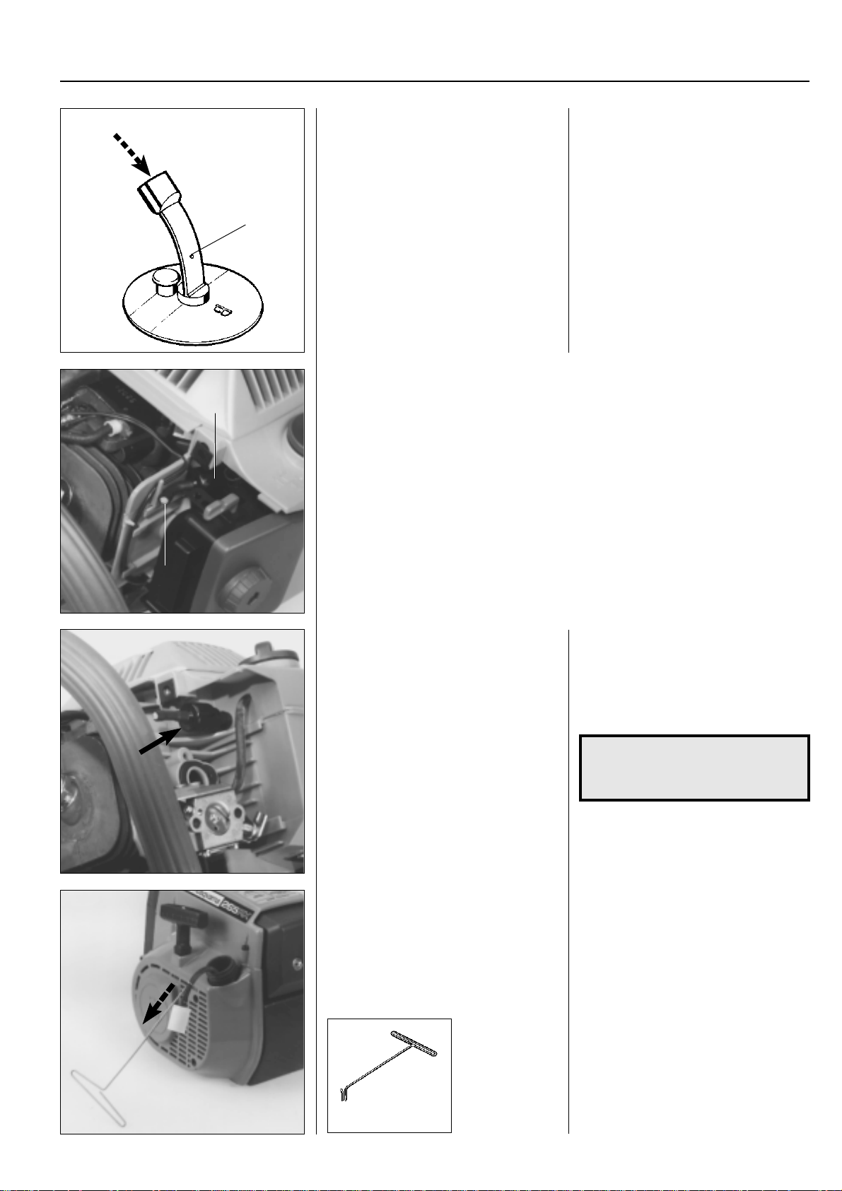
The tank ventilation is integrated in the
fuel cap’s gasket
Blow through the flat hose to check that it
is open.
A
Models 225 H60, 225 H75
A
B
T ank ventilation consists of a non-return valve (A) that opens for vacuum and pressure.
It is located in the carburettor housing.
●
Empty the fuel tank and tighten the fuel cap.
●
Clean the filter (B).
●
Remove the fuel pipe from the carburettor and connect the pressure tester
502 50 38-01 resp. vacuum tester 502 50 37-01 to the pipe.
Pressure: Pump a pressure of 50 kPa (0.5 bar), the pressure should drop to
20 kPa (0.2 bar) within 60 seconds.
Vacuum: Reduce the pressure to –50 kPa (0.5 bar).
The pressure should rise again to –20 kPa (0.2 bar) within 30 seconds.
Model 141B
The tank ventilation is integrated in the
fuel cap’s gasket and can easily be dismantled for replacement.
Pull off the flat hose from the pin on the
rubber washer and blow through the hose
to check that it is not blocked.
Check that the hole (A) is open.
3
Replace the valve if its performance is not
satisfactory.
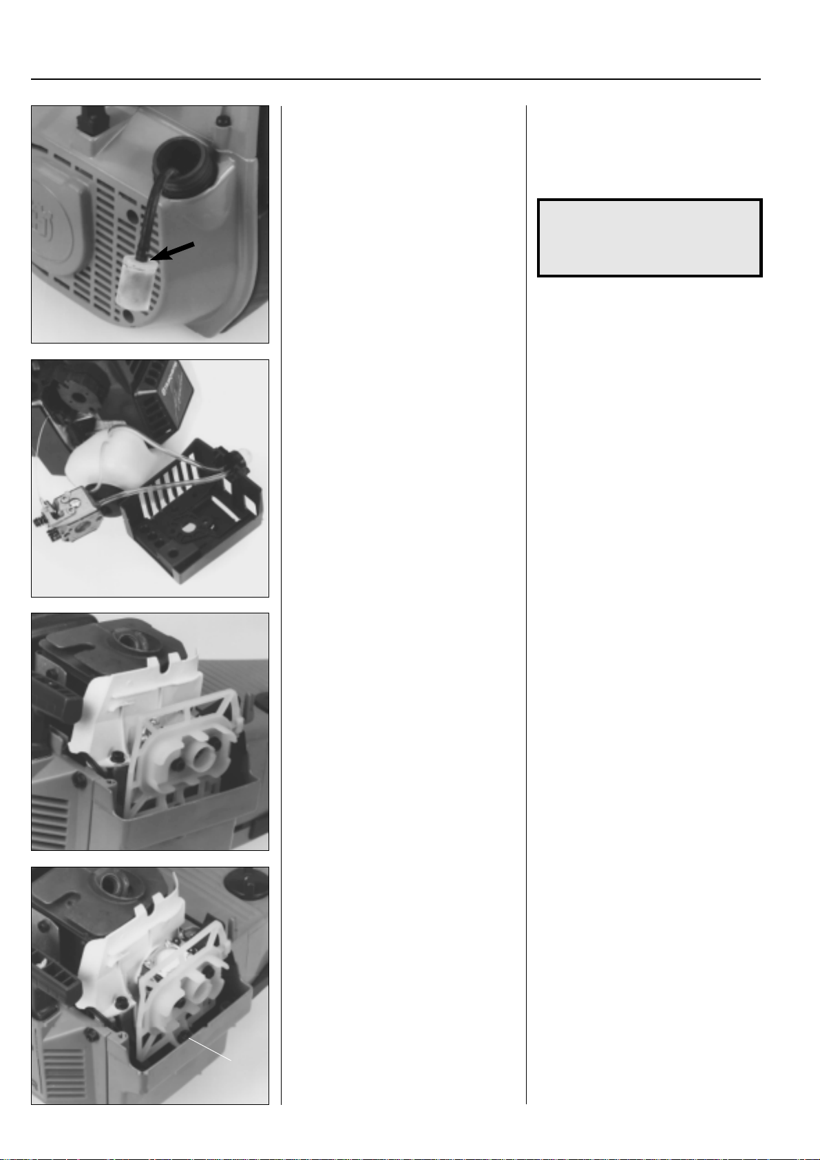
Fuel filter
All models
The fuel filter can be removed through the
tank's filler hole.
If the valve does not work as intended it
should be replaced.
Dismantle the air filter holder and swing
out the carburettor.
Pry up the non-return valve from the fuel
tank using a screwdriver.
NOTE!
Fit the new valve with the short
shoulder towards the fuel tank.
Fuel filter
All models
A fuel filter is located on the fuel pipe. It is
accessible through the filler hole. Pull out
the filter using your fingers or using tool
502 50 83-01.
502 50 83-01
www.mymowerparts.com
43
Page 45
For Husqvarna Parts Call 606-678-9623 or 606-561-4983
3
Fuel system
Clean the outside of the filter if it is too
heavily contaminated.
Replace the filter if necessary.
Primer pump
Models 322, 325, Mondo, 18H
The primer pump facilitates cold starts.
The pump cannot be repaired and must
be replaced if it stops working.
Note how the fuel hoses are connected to
simplify assembly.
If it is too heavily contaminated it can be
cleaned on the outside using a brush.
In all other cases it should be replaced.
Check the fuel pipe with regard to crack-
ing and leakage.
NOTE!
Ensure that the filter's connection
shoulder is press into the fuel pipe
as far as possible.
Primer pump
Models 322, 325, Mondo, 18H
The primer pump has the task of facilitating the start of the engine when cold. The
pump fills the carburettor with fuel before
attempting to start the engine. This also
prevents vapour bubbles from blocking
the narrow fuel channels.
If the pump does not work it must be
replaced.
Note how the fuel hoses are connected to
simplify assembly .
Carburettor
Dismantling all models
Dismantle the cylinder cover and blow out
the carburettor compartment with compressed air.
Dismantle the carburettor . Dismantle the air filter and air filter holder,
Carburettor
Dismantling all models
●
Dismantle the cylinder cover.
●
Close the choke damper to prevent dirt
from entering the engine.
●
Blow out the carburettor compartment
with compressed air.
fuel pipe, throttle cable and choke lever.
Lift out the carburettor.
Tip!
Let the lower screw (A model 245) remain
in the crankcase. This simplifies subsequent assembly .
44
A
www.mymowerparts.com
Page 46
For Husqvarna Parts Call 606-678-9623 or 606-561-4983
Fuel system
3
1
2
2
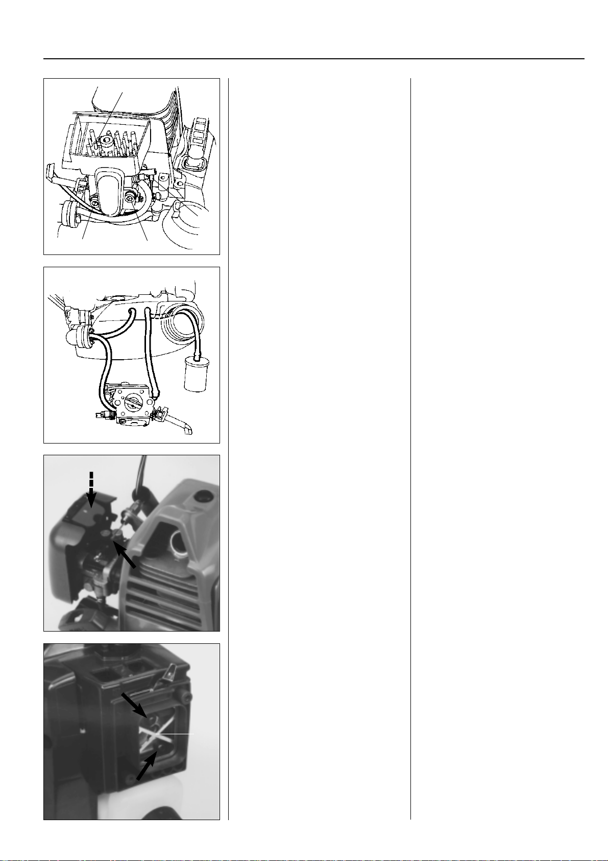
Models 322, 325
Disconnect the throttle cable from the
carburettor.
Dismantle the carburettor.
Lift off the carburettor and note how the
fuel hoses are connected.
Models 322, 325
1. Disconnect the throttle cable from the
lever arm on the carburettor.
2. Loosen the carburettor screws.
3. Remove the screws holding the air
filter holder.
Lift off the carburettor and note how the
fuel hoses are connected.
3
Model 122
Disconnect the throttle cable from the
carburettor. Fold down the air filter cover
and dismantle the carburettor.
Model Mondo
Loosen and turn the carburettor to the
side.
A
Model 122
Disconnect the throttle cable from the
lever arm on the carburettor.
Press down the snap-lock and swing down
the air filter so that the screws holding the
carburettor are accessible.
Model Mondo
Remove the filter support (A) and both
screws that hold the carburettor cover
and the carburettor.
Note where the screws are placed so that
they can be positioned correctly when
assembling.
www.mymowerparts.com
45
Page 47
For Husqvarna Parts Call 606-678-9623 or 606-561-4983
3
Fuel system
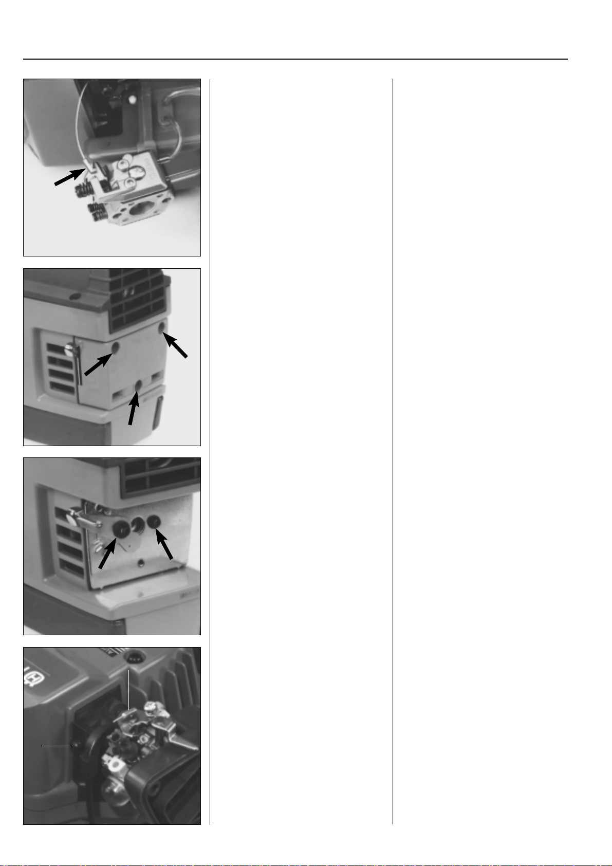
Bend out the throttle cable.
Remove the fuel pipes.
Model 32
Dismantle the air filter cover with filter.
Bend out the throttle cable.
Remove the fuel pipes. If they are hard to
remove, use a screwdriver to press them
off.
Note how the hoses are fitted so they can
be correctly reassembled.
Model 32
The carburettor is located on the crankcase and becomes accessible when the 3
screws and the air filter cover and air filter
are removed.
Dismantle the carburettor screws and lift
out the carburettor.
Model 18H
A
B
Disconnect the throttle cable from the
carburettor.
Remove the carburettor screws, choke
lever and cover plate.
Note how the washers on the choke lever
screws sit.
Now lift out the carburettor.
Model 18H
Disconnect the throttle cable from the
carburettor.
Remove the screw (B) and unhook the
throttle cable from the lever arm on the
carburettor (A).
46
www.mymowerparts.com
Page 48
For Husqvarna Parts Call 606-678-9623 or 606-561-4983
Fuel system
Dismantle the carburettor from the cylinder.
Model 141B
Dismantle the cover together with the
rotary valve and cable bracket.
A
Loosen the carburettor screws and lift out
the air filter holder and carburettor.
Remove the fuel hoses from the carburettor.
Model 141B
Loosen both screws (A) and lift off the
cover together with the rotary valve and
cable bracket.
Let the parts remain hanging from the
throttle cable if they are not damaged and
do not need to be replaced.
3
A
Dismantle the carburettor from the cylinder.
B
A
B
A
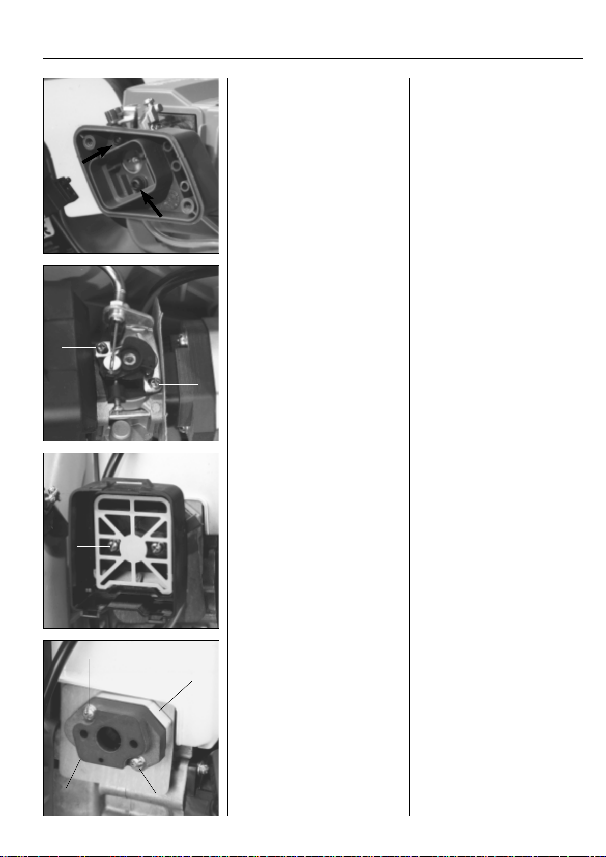
Remove the screws and lift out both distance pieces.
C
Inspect the fibre distance piece with regard to crack formation.
Replace the distance piece if necessary .
Remove the air filter support (A) and both
screws (B) that hold the carburettor on
the cylinder.
Lift off the air filter holder and carburettor
from the cylinder.
Remove the screws (A), the fibre distance
piece (B) and the aluminium distance
piece (C).
Inspect the fibre distance piece with regard to crack formation. Replace the distance piece if necessary.
B
A
47
www.mymowerparts.com
Page 49
For Husqvarna Parts Call 606-678-9623 or 606-561-4983
3
Fuel system
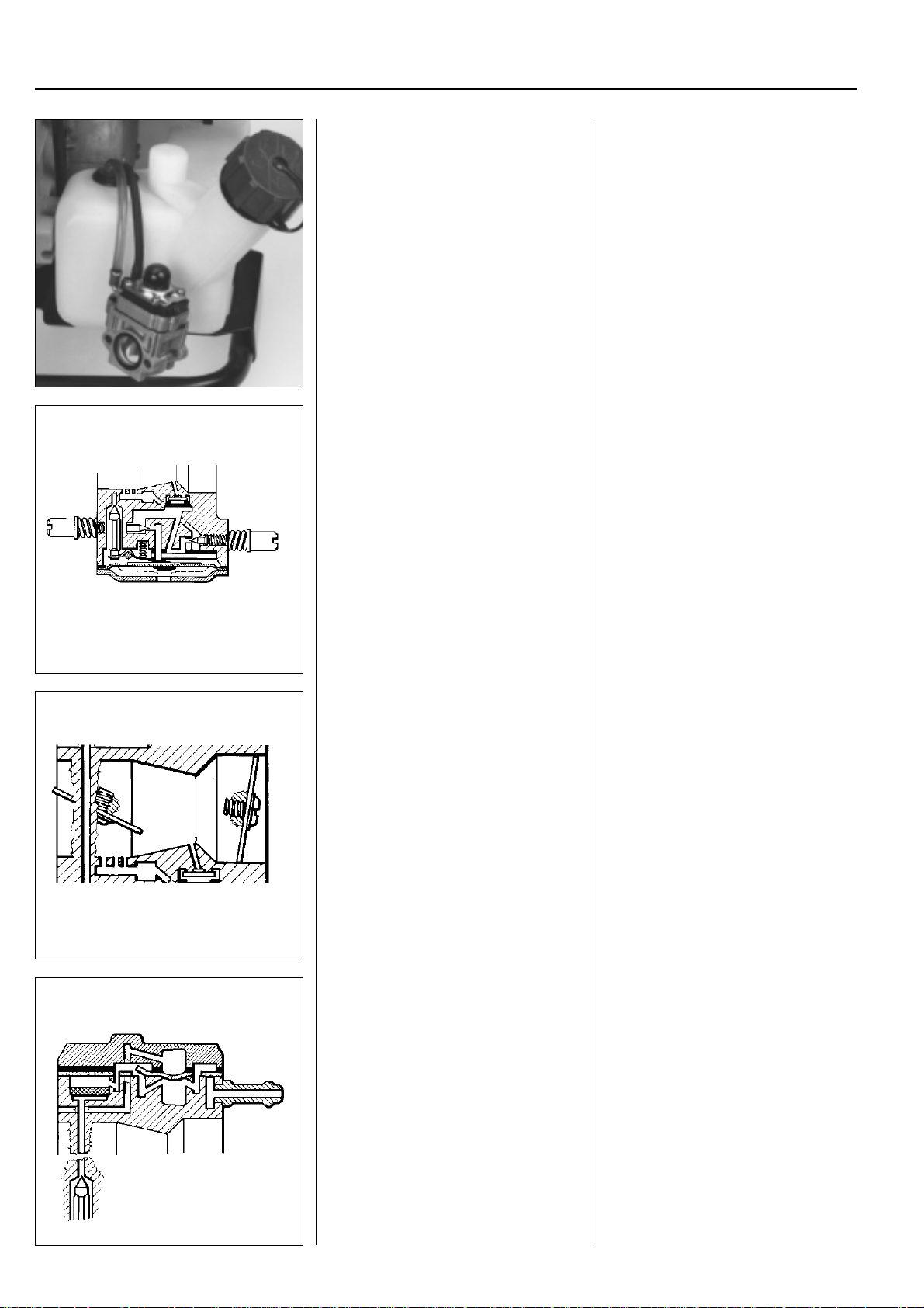
Pull off the fuel hoses and lift out the
carburettor.
Design of the carburettor
The carburettor can be divided in three
different sub-systems: metering unit, mixing venturi and pump unit.
Metering unit
The unit houses the jets and fuel control
functions.
Lift out the carburettor and note how both
fuel hoses are connected to the carburettor (rubber hose on the straight nipple).
Design of the carburettor
The carburettor can be divided in three
different sub-systems: metering unit, mixing venturi and pump unit.
Metering unit
The unit houses the jets and fuel control
functions.
The needle valves and control diaphragm
are vital to the operation of the carburettor.
Mixing venturi
Fuel and air are mixed here.
Pump unit
Pumps fuel from the tank to the carburettor.
Mixing venturi
The fuel and air are mixed in the correct
proportions in this part of the carburettor.
The choke and throttle valve are placed
here.
In the centre of the venturi (narrowest
part of the flow area) is the main jet.
Pump unit
The pump diaphragm, which pumps fuel
from the tank to the carburettor's metering unit is located here.
The diaphragm is actuated by the pressure variations in the engine's crankcase
via a pulse channel.
If the channel is blocked, e.g. by grease,
a gasket turned the wrong way or carbon
deposits the pump unit will not work and
the engine cannot be started.
48
www.mymowerparts.com
Page 50
For Husqvarna Parts Call 606-678-9623 or 606-561-4983
Fuel system
Stripping the carburettor
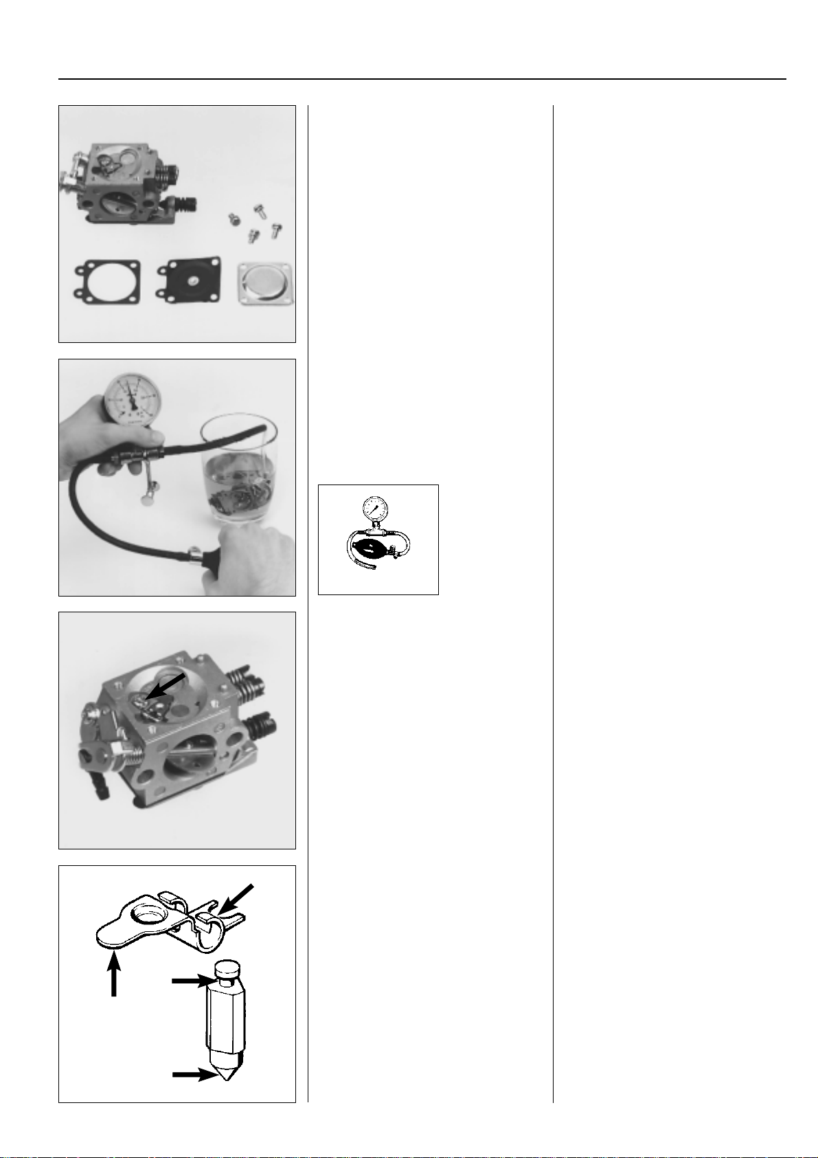
General
Remove the control diaphragm and check
for damage.
Replace if necessary.
Pressure test the metering unit.
3
Stripping the carburettor
General
Remove the 4 screws holding the control
diaphragm cover and lift off the cover.
Carefully remove the control diaphragm
and the gasket.
Check the diaphragm for holes and wear
on the pin.
Replace the diaphragm if necessary.
Connect pressure tester 502 50 38-01 to
the fuel pipe nipple.
Lower the carburettor into a bowl of petrol
to make it easier to discover any leakage.
Test with 50 kPa.
No leakage is permitted.
502 50 38-01
With leakage – dismantle the needle valve.
Check the needle valve and lever arm for
wear.
Replace damaged parts.
In the event of leakage dismantle the
needle valve.
Loosen the screw and lift out the lever
arm, shaft, needle valve and spring.
Check the needle valve for wear to the tip
and groove for the lever arm.
Check the lever arm for wear to the lever
arm groove and wear to the contact point
with the control diaphragm.
Replace damaged parts.
www.mymowerparts.com
49
Page 51
For Husqvarna Parts Call 606-678-9623 or 606-561-4983
3
Fuel system
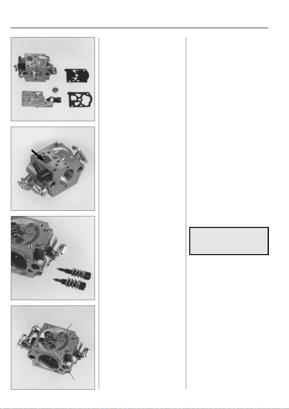
Remove the pump diaphragm.
Check the diaphragm for wear.
Remove the fuel screen.
Remove the screw that holds the cover
over the pump membrane.
Lift off the cover , gasket and diaphragm.
Check the diaphragm for wear to the
valve flaps. If the valve flaps are bent the
pump will not work satisfactorily.
Also hold it up to a light to see if there are
any holes in the material.
Carefully remove the fuel screen by using, e.g. a needle.
Unscrew the jet needles. Skruva bort munstycksnålarna.
NOTE!
Remember how the needles were
placed. (E.g. the H needle a little
shorter than the L needle).
Walbro
Dismantle the plug (1) and main jet (2).
1
Walbro
Drill a small hole in the plug (1) and
carefully pry it out using a pointed object.
Press out the main jet (2) using a suitable
punch.
50
2
www.mymowerparts.com
Page 52
For Husqvarna Parts Call 606-678-9623 or 606-561-4983
3Fuel system
Model Mondo and model 32 have a version of the previously described carburettor with 2 plugs.
Dismantle the plugs.
Tillotson
Dismantle the plugs.
Model Mondo and model 32 have a version of the previously described carburettor with 2 plugs.
Drill a small hole in the plugs and carefully
pry them out using a pointed object.
Tillotson
Drill a small hole in the plugs and carefully
pry them out using a pointed object.
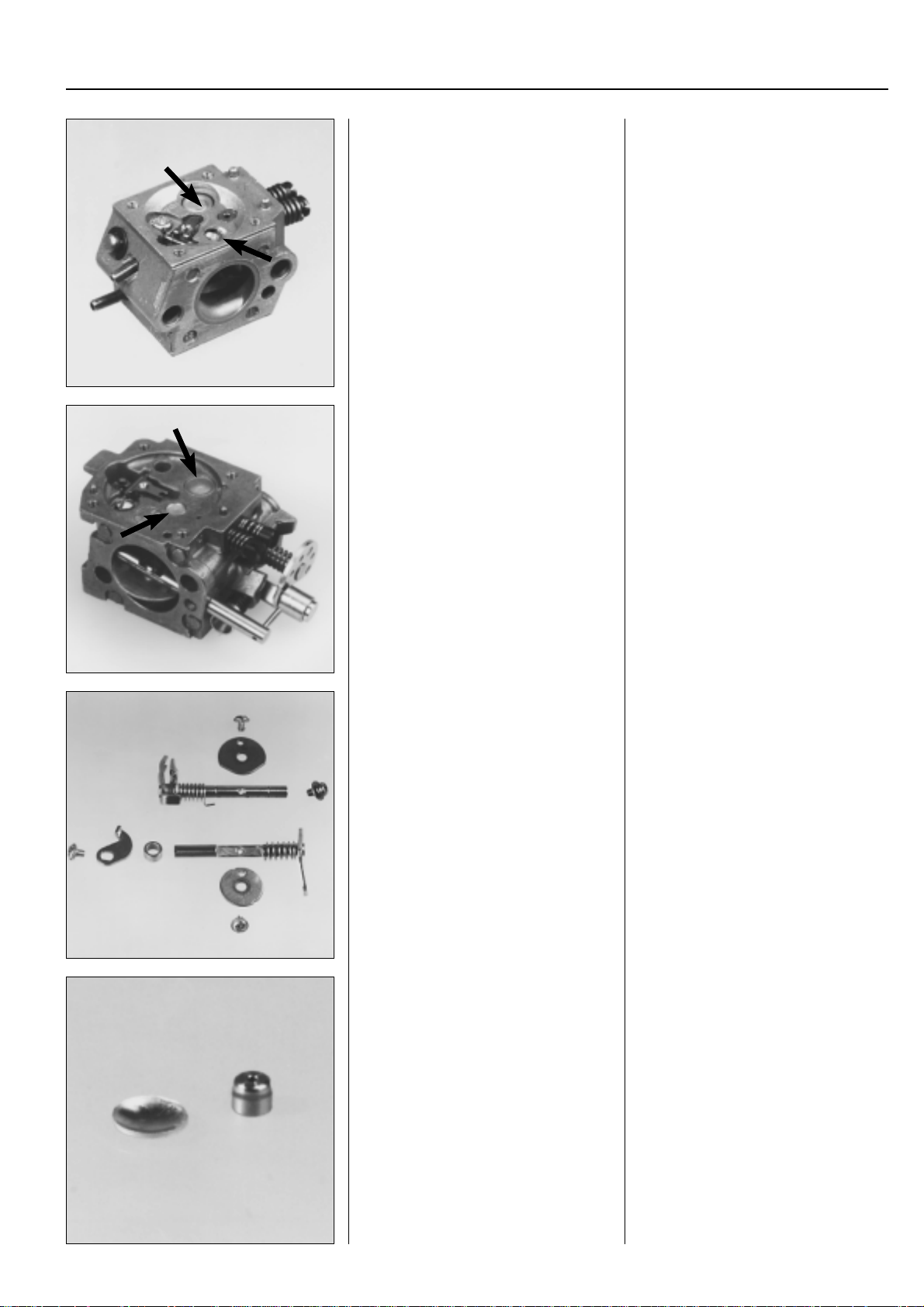
Check the plates and spindles
for wear.
Replace damaged parts.
Reassembling the carburettor
Blow out the carburettor housing.
Fit a new plug.
Fit a new main jet.
Dismantle the plates and spindles. If these
parts are worn this will cause idling to be
disruptive.
Always replace the plate and spindles at
the same time.
Reassembling the carburettor
●
Blow out all the channels in the carburettor housing.
●
Fit a new plug.
Use a suitable punch to attain com-
plete tightness.
●
Press in a new main jet. This should be
flush with the carburettor housing.
www.mymowerparts.com
51
Page 53
For Husqvarna Parts Call 606-678-9623 or 606-561-4983
3
Fuel system
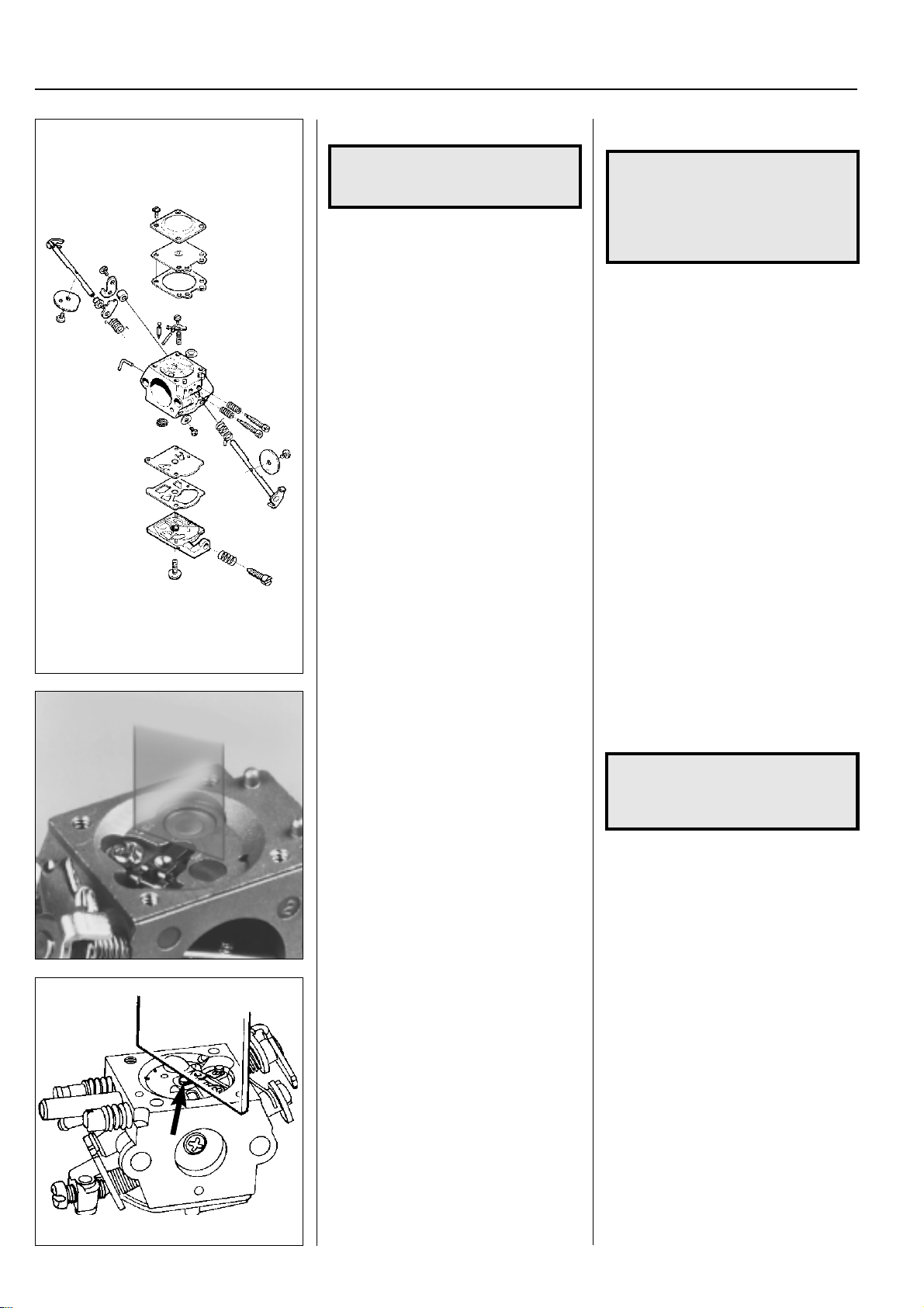
Fit the plates and spindles.
NOTE!
Use Loctite on the plate screws.
Fit the pump unit's components in the
reverse order set out for dismantling.
●
Fit the plates and spindles.
NOTE!
Check that the plate is facing the
right way and that it seals correctly
in the closed position.
Use Loctite on the plate screws.
Tips!
Any number designation on the plate
should be possible to read from the outside.
Replace the fuel screen if it is damaged or
if it cannot be cleaned.
Place the pump diaphragm closest to the
carburettor housing, then the gasket and
cover.
Assemble the components in the mixing
venturi in the reverse order set out for
dismantling.
Zama
Design, function and servicing correspond
with the Walbro carburettor.
Assemble the components in the mixing
venturi in the reverse order set out for
dismantling.
NOTE!
The H needle is a little shorter than the
L needle.
Check that the lever arm is level with the
carburettor housing (Walbro) or level with
the gasket face (Tillotson).
Too high setting = too much fuel.
Too low setting = too little fuel.
Zama
Zama has the same design and function
as the Walbro carburettor, which means
that servicing is also carried out in the
same way .
The lever arm should lie flush with the
carburettor housing’s contact face.
52
www.mymowerparts.com
Page 54
For Husqvarna Parts Call 606-678-9623 or 606-561-4983
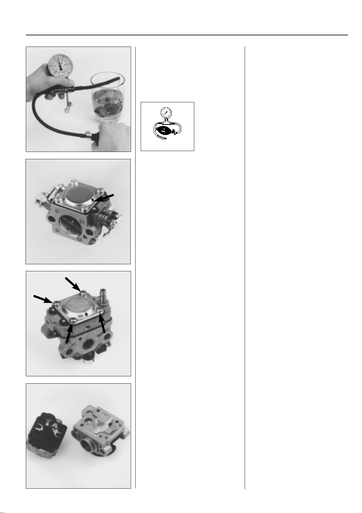
Fuel system
General
Check that the carburettor does not leak.
No leakage is permitted at a pressure of
50 kPa.
502 50 38-01
Fit the control diaphragm.
3
General
Connect the pressure tester no.
502 50 38-01 to the fuel inlet on the
carburettor.
Pump up to a 50 kPa pressure.
Lower the carburettor into a bowl of petrol
to discover any leakage.
No leakage is permitted.
Place the gasket on the carburettor housing and then the control diaphragm.
Check that the air hole in the cover is
open and screw the cover in position.
Dismantling, assembling
Model 122
This model has a special Walbro carburettor with pump and metering units placed
on the same side as the venturi.
Dismantle the control diaphragm.
Dismantle the pump and metering unit. Separate the pump and metering unit
Dismantling, assembling
Model 122
This model has a special Walbro carburettor where the pump and metering unit
are placed on the same side as the venturi.
Remove the 4 screws and lift off the cover
and control diaphragm.
from the carburettor body.
Pry carefully using a screwdriver.
www.mymowerparts.com
53
Page 55
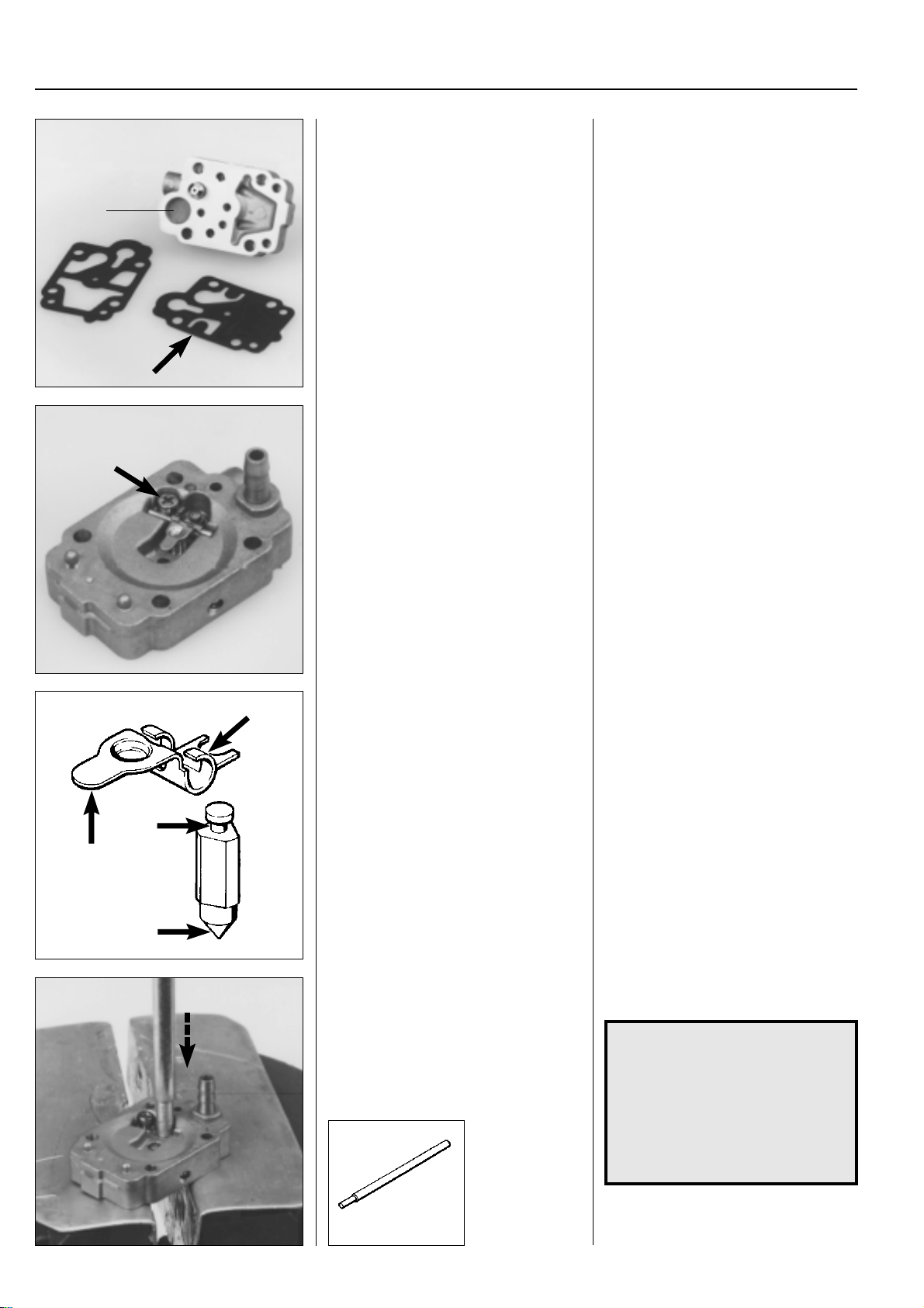
For Husqvarna Parts Call 606-678-9623 or 606-561-4983
3
Fuel system
Remove the pump diaphragm and inspect for wear and damage.
Clean or replace the fuel screen (1).
1
Dismantle the lever arm and needle valve
to check for wear, replace if necessary.
Carefully remove the pump diaphragm
and its gasket.
Check the pump diaphragm for wear to
the valve flaps. Also hold it up to a light to
check the material for holes.
Clean the fuel screen (1). Remove using
a needle for replacement.
Loosen the screw and lift off the lever
arm, shaft, needle valve and spring.
Check the lever arm and needle valve for
wear.
Replace damaged components.
Replacing the needle valve seat. Press out the needle valve seat for re-
Check for wear to the lever arm on the
points of contact on the control diaphragm
and on the cut-out for the needle valve.
Also check for wear to the needle valve on
the tip and groove for the lever arm.
Replace damaged components.
placement.
NOTE!
Replace the seat, needle valve and
lever arm at the same time.
The needle valve seats should be
level with the carburettor housing.
Use a vice with soft jaw guards to
avoid damaging the needle valve
seat.
54
502 02 61-02
www.mymowerparts.com
Page 56
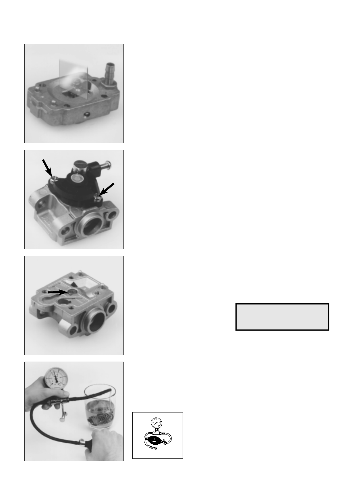
For Husqvarna Parts Call 606-678-9623 or 606-561-4983
Fuel system
Check the position of the lever arm.
Replace the entire throttle valve mechanism if the throttle pivot is worn.
3
Assemble the components in the reverse
order set out dismantling.
Check that the lever arm is level with the
diaphragm housing.
Too high setting = too much fuel.
Too low setting = too little fuel.
The entire throttle vale mechanism can be
lifted off for replacement once the two
screws have been removed.
Note which way, e.g. the idling screw is
facing so the new mechanism is positioned correctly .
Dismantle the main jet by prying it out of
the carburettor housing using a small
screwdriver.
Assemble the carburettor and pressure
test it.
The carburettor's main jet can be removed for replacement.
Use a small screwdriver to pry the main
jet out of the carburettor housing.
Take care not to lose the small O-ring
under the main jet.
NOTE!
Do not dismantle the plastic pipe
in the throttle housing.
Assemble the carburettor in the reverse
order set out for dismantling.
Check that the carburettor does not leak
following the procedure described on
page 46.
502 50 38-01
www.mymowerparts.com
55
Page 57
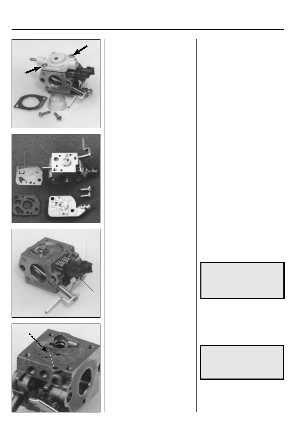
For Husqvarna Parts Call 606-678-9623 or 606-561-4983
3
Fuel system
Dismantling, assembling
Model 18H
The carburettor is made by Zama.
Dismantle the primer pump’s bellows and
cover over the control diaphragm.
Dismantle the pump diaphragm and fuel
2
1
screen.
Dismantling, assembling
Model 18H
The carburettor is made by Zama.
It has the same principle design as the
Tillotson and W albro carburettors.
Dismantle the primer pump’s bellows and
then the cover over the control diaphragm.
Inspect the control diaphragm and needle
valve in the same way as previously described.
Remove the screws holding the cover
over the pump diaphragm.
Lift off the cover, pump diaphragm and
gasket.
Check the diaphragm (1) in the same way
as previously described.
Carefully remove the fuel screen (2) using,
e.g. a needle.
Unscrew the jet needles. Unscrew the jet needles.
L
H
Press out the main jet for possible replacement using a suitable punch.
1
The plastic sleeves must first be removed
using a screwdriver on carburettors with
movement limiters.
NOTE!
Notice how the needles are posi-
tioned.
(For example, the H-needle is a
little shorter than the L needle).
The main jet can be pressed out for possible replacement using a suitable punch.
NOTE!
When the new jet is fitted it must
not be pressed in further than so
that edge (1) on the jet lies flush
with the carburettor housing.
56
www.mymowerparts.com
Page 58
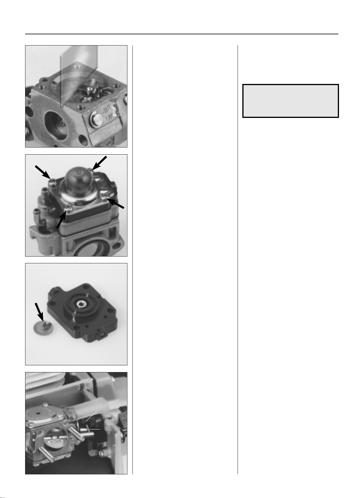
For Husqvarna Parts Call 606-678-9623 or 606-561-4983
Fuel system
Assemble the carburettor and pressure
test it.
Wait to fit the movement limiters on the jet
needles.
Dismantling, assembling
Model 141B
Remove the screws and lift off cover with
the pump bellows.
3
Assemble the carburettor in the reverse
order as set out for dismantling.
The needle valve lever arm should be
adjusted to a level flush with the carburettor housing’s contact face.
NOTE!
The control diaphragm and pump
diaphragm should lie closest to the
carburettor housing!
Wait to fit the movement limiters on the jet
needles.
Dismantling, assembling
Mod. 141B
This carburettor has a rotary valve instead of a throttle valve.
Remove the 4 screws and lift off cover
with the pump bellows.
Lift off the cover above the control diaphragm and carefully remove the non–
return valve. Check that it opens and
closes.
Continue to dismantle and assemble the
carburettor in the same way as described
for model 122 (page 53).
Assembly
Model 265
Fit the screwdriver guide over the jet
screws and slide the carburettor in position over the studs.
2
1
Lift off the cover over the control diaphragm.
Carefully remove the non-return valve
and check that it opens and closes by
pressing together the valve’s short sides
with you thumb nail.
Hold the valve against a light to make it
easier to see whether it closes fully.
Continue to dismantle and assemble the
carburettor in the same way as described
for model 122 (page 53).
Assembly
Model 265
Before the carburettor can be fitted on the
cylinder the screwdriver guide should be
placed over the jet screws.
Turn the choke lever to "CHOKE" and
close the choke valve about 1/4. No more
than so the pin (1) on the choke shaft can
just bypass the choke lever's connector (2).
www.mymowerparts.com
57
Page 59
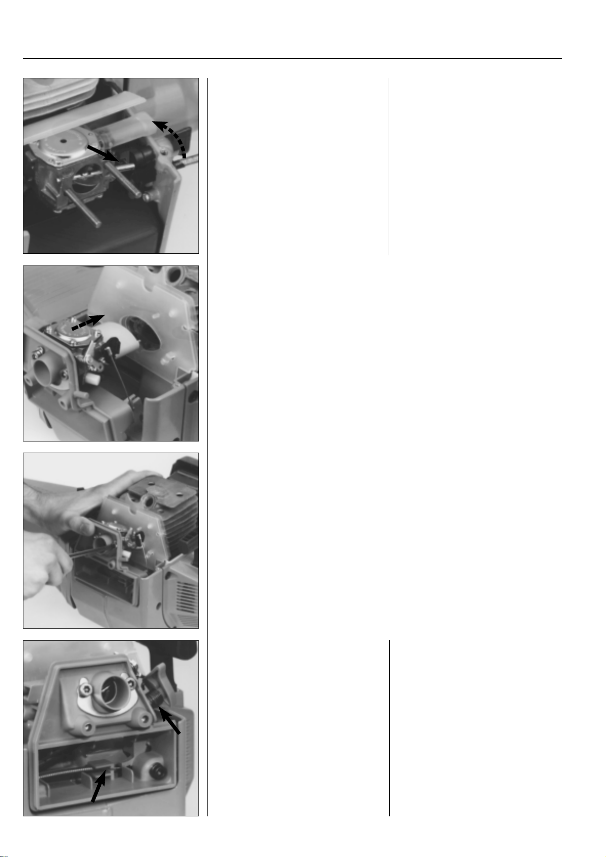
For Husqvarna Parts Call 606-678-9623 or 606-561-4983
3
Fuel system
Check that the pin on the choke shaft
goes in the groove on the choke lever's
connector.
Connect the fuel pipe and fit the remaining components.
Model 250
Assembly sequence:
1. Secure the intake gasket on the cylinder.
2. Place the radiant heat guard on the crankcase.
3. Place the carburettor in the air filter holder and slide in the carburettor screws.
Do not forget the U-shaped reinforcement plate.
4. Connect the throttle cable and fuel pipe.
5 Place the gasket in position on the carburettor. Check that it faces the right way so
the pulse channel is not blocked.
6. Place the distance piece against the carburettor.
7. Fit the carburettor on the cylinder.
Slide the carburettor towards the cylinder
at the same time as the choke lever is
moved to the open position. Make sure
the pin on the choke shaft goes in the
groove on the choke lever's connector.
Connect the fuel pipe, fit the filter holder
and the remaining components.
8.Press the carburettor against the cylinder using your thumb and carefully tighten the
screws so that they do not cross thread.
9.Place the remaining two screws in the air filter holder.
10.Tighten all four screws.
Check that the throttle cable seats correctly in the air filter cover.
Fit the choke lever.
Check that the throttle cable seats correctly in the air filter cover.
Apply a little grease to the bearing stud.
Position the spring and fit the choke lever.
Check that the spring is capable of moving the valve back.
58
www.mymowerparts.com
Page 60
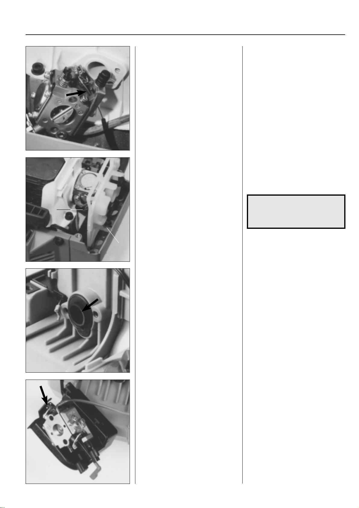
For Husqvarna Parts Call 606-678-9623 or 606-561-4983
Fuel system
Models 240/245
Connect the fuel pipe and throttle cable.
Position the choke lever in the air filter
holder and fit the carburettor with the
holder on to the cylinder.
B
Models 240/245
First connect the fuel pipe to the carburettor and then fit the throttle cable.
Note the routing of the cable between the
carburettor housing and the idling screw
likewise the connection to the lever arm
on the carburettor.
Secure the gasket on the carburettor with
grease.
Check that it faces the right way; not
blocking the pulse channel.
Position the choke lever in the air filter
holder and slide the carburettor screws
through holes and the carburettor housing.
Position the slot in the air filter housing
(A) under the screw in the crankcase.
NOTE!
The washer should be placed be-
tween the crankcase and the air
filter holder.
3
Now tighten the screws.
A
Model 225/232/235
Check that the plastic ring is in position in
the inlet pipe.
Place the choke lever and carburettor in
position in the air filter cover.
Connect the fuel pipe.
Check that the choke lever grips in the
groove (B) on the carburettor's choke
lever arm.
Model 225/232/235
Check that the small plastic ring is in
position in the elastic inlet pipe. This prevents the pipe from deforming.
Position the choke lever in the air filter
cover and then the carburettor. Check
that the choke lever enters the groove on
the carburettor's lever arm.
Connect the fuel pipe.
www.mymowerparts.com
59
Page 61
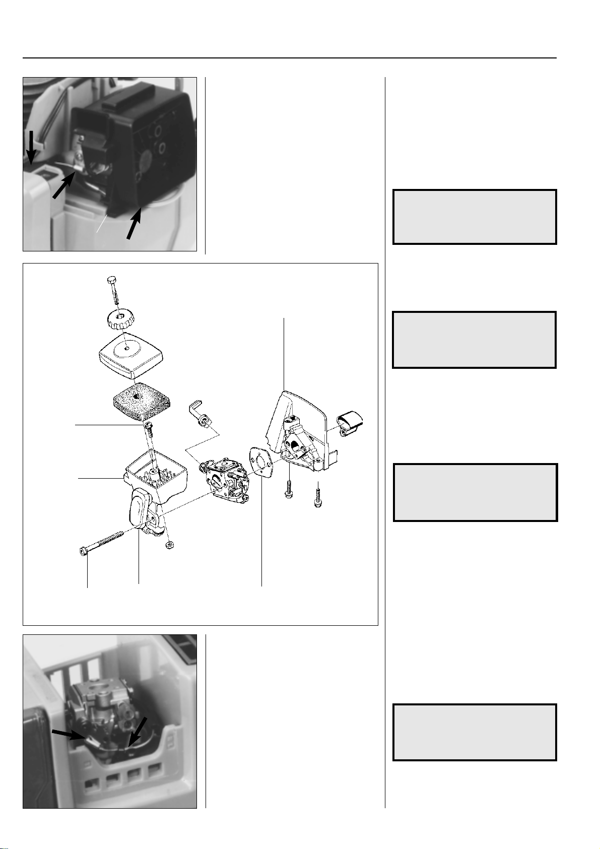
For Husqvarna Parts Call 606-678-9623 or 606-561-4983
3
Fuel system
Connect the throttle cable and bolt on the
carburettor.
Make sure the cable sits correctly in the
cable guides.
A
4
Slide the carburettor screws through the
air filter holder and the carburettor.
Then connect the throttle cable and bolt
the carburettor onto the cylinder. No gasket or gasket sealant is needed.
Make sure the cable sits correctly in the
cable guides.
Make sure the fuel pipe is not crushed
between the crankcase and air filter holder.
NOTE!
The air filter holder should be in-
serted into the guide (A) on the
crankcase.
Models 322, 325
1. First assemble the fuel hoses on the
carburettor.
NOTE!
The hose, with the fuel filter in the
tank, should be fitted on the carburettor’s inlet side (pump c hamber).
2. Keep the air filter holder (1) in position
on the carburettor.
3. Slide in the carburettor screws (2).
5
1
2
6
Model 32
Position the carburettor gasket and connect the fuel pipe and throttle cable.
3
4. Position the gasket (3) and screw together the entire carburettor assembly
against the distance piece (4). Tighten
the carburettor screws crosswise.
NOTE!
Do not forget the screw (5) that holds
the air filter holder against the distance piece.
5. Connect the throttle cable to the lever
arm on the carburettor.
Make sure the cable enters the correct slot in the clutch cover and in the
guide on the air filter holder (6).
Assemble the remaining parts in the reverse order as set out for dismantling.
Model 32
Position the carburettor gasket on the
crankcase.
Connect the fuel pipe and throttle cable to
the carburettor.
60
NOTE!
Connect the cable in the right hole
on the lever arm and ensure it pulls
correctly.
www.mymowerparts.com
Page 62
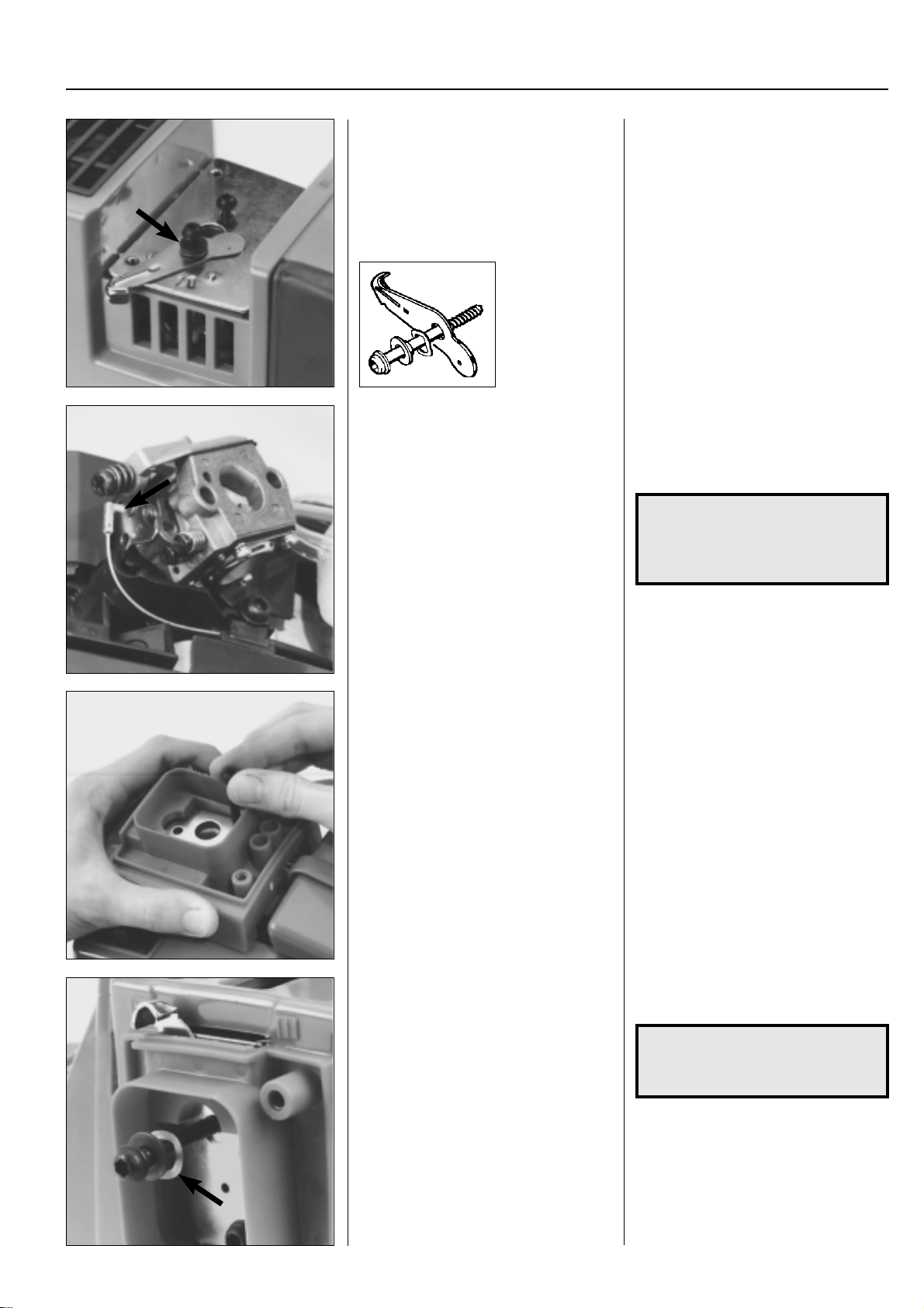
For Husqvarna Parts Call 606-678-9623 or 606-561-4983
Fuel system
Position the carburettor and cover plate.
Fit the choke valve and tighten the carbu-
rettor screws.
Model Mondo
Connect the throttle cable.
Connect the fuel pipes.
Position the carburettor.
3
Align the carburettor over the securing
holes and position the cover plate.
Fit the carburettor screws, bear in mind
the position of the curved washer and
stop shoulder by choke valve. Turn the
choke valve the right way!
Tighten the carburettor screws and fit the
air filter.
Model Mondo
● Connect the throttle cable to the throttle valve's lever arm.
● Connect the fuel pipes.
NOTE!
Select the right hole. See photo.
Make sure the fuel pipes are not
mixed up. See photo on page 39.
Check that the intake gasket is placed
correctly and position the carburettor.
Watch the routing of the throttle cable.
Hold the carburettor in place and fit the air
filter holder and support plate with the
lower screw.
Fit the choke valve. Place the choke valve in the air filter
Hold the carburettor in place.
Position the air filter holder with its sup-
port plate on the carburettor.
Guide the holder and carburettor by us-
ing the lower screw.
Check that the gasket has not moved.
holder and tighten the screw.
NOTE!
The curved washer should rest
against the valve.
www.mymowerparts.com
Check that the stop sleeve is seated correctly in the hole in the valve and that it
can be opened and closed without jamming.
61
Page 63
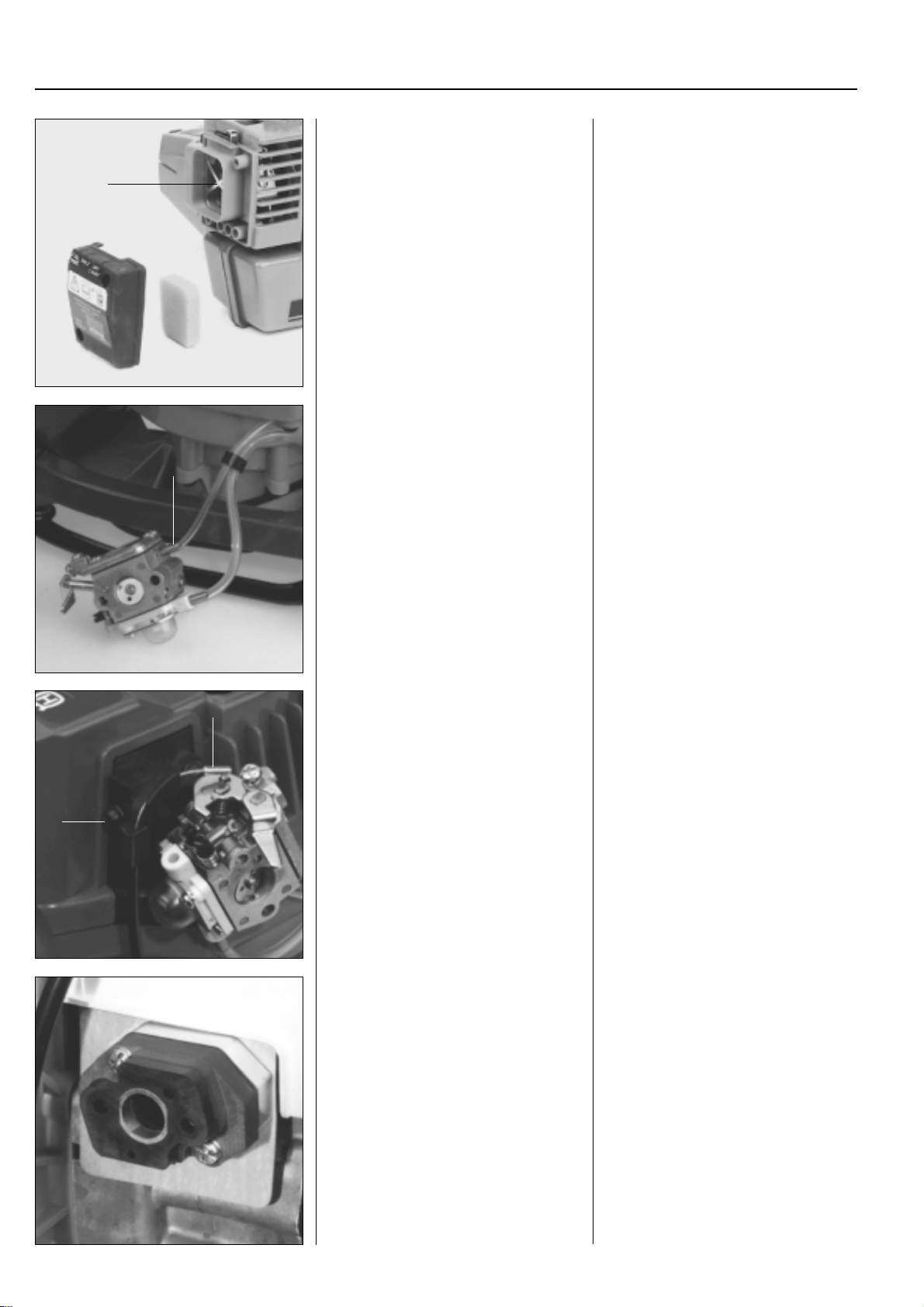
For Husqvarna Parts Call 606-678-9623 or 606-561-4983
3
Fuel system
Fit the filter support (A), air filter and filter
cover.
Clean/replace the air filter if necessary.
A
Model 18H
Connect the fuel hoses.
A
Fit the filter support (A). This must be
used to prevent particles from the air filter
being drawn into the carburettor.
Now fit the air filter (clean first in tepid,
soapy water if necessary) and air filter
cover.
Model 18H
Connect the fuel hoses on the carburettor.
The thin hose (A) is connected to the
nipple on the carburettor body (pump
diaphragm).
A
B
Connect the throttle cable.
Tighten the air filter holder.
Clean or replace the air filter.
Model 141B
Fit the distance piece on the cylinder.
Connect the throttle cable (A) to the throttle valve’s lever arm.
Secure the cable guide (B) on the distance piece.
Tighten the air filter holder.
Do not forget the gasket between the
carburettor and the distance piece!
Clean or replace the air filter before as-
sembly.
Clean in tepid soapy water.
Fit the air filter cover.
Model 141B
Pay special attention that the distance
pieces and gaskets face the right way and
do not block the impulse channel when
fitted on the cylinder.
Secure the distance piece closest to the
carburettor with a little grease. This facilitates carburettor assembly.
62
www.mymowerparts.com
Page 64
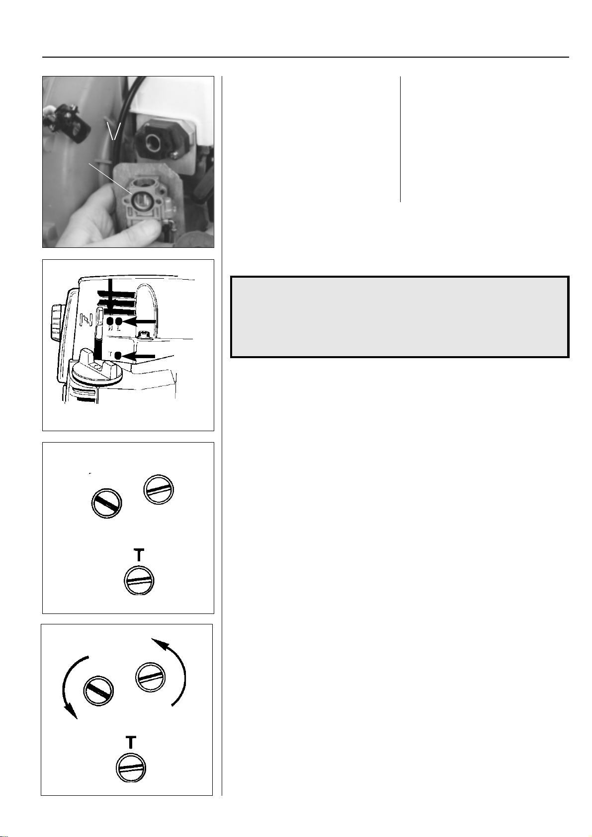
For Husqvarna Parts Call 606-678-9623 or 606-561-4983
Fuel system
Turn the carburettor so that the recessed
sealing ring (A) comes against the air
filter holder.
Tighten the carburettor and air filter holder
against the cylinder.
Slide down the rotary valve in the carbu-
A
rettor and screw on the cover.
Check that the throttle works.
Turn the carburettor so that the recessed
sealing ring (A) comes against the air
filter holder.
Place the carburettor screws in the air
filter holder (do not forget the choke valve)
and then slide the carburettor on the
screws.
Tighten the carburettor against the cylinder.
Slide down the rotary valve in the carburettor housing. Tighten the cover and
check that the throttle is turned easily
when accelerating and that it rests against
the idling screw when the throttle is released.
3
Carburettor settings
WARNING!
!
The clutch drum and driveline must, under all circumstances, be
fitted when testing running the engine after adjusting the
carburettor.
Otherwise there is a risk that the clutch can become detached
and cause serious personal injury.
H
H
L
L
Function
The carburettor has the task of delivering a combustible air/fuel mixture to the cylinder.
The amount
The mixture's composition
”H” and ”L”.
The needles must be correctly adjusted so that the engine can give maximum power
at different speed, run smoothly when idling and react quickly when accelerating.
The carburettor setting can vary a little depending on the humidity , temperature and air
pressure.
L = Low speed needle
H = High speed needle
T = Idle speed adjuster screw
● The fuel quantity in relation to the air flow permitted by the throttle opening is
adjusted by the L and H needles. T urning the needles clockwise gives a leaner fuel
mixture (less fuel) and turning them anticlockwise gives a richer fuel mixture (more
fuel). A
● The T-screw regulates the position of the throttle while the engine is idling. T urning
the screw clockwise gives a higher idling speed while turning it anticlockwise gives
a lower idling speed.
Basic setting
The carburettor is set to its basic setting when test run at the factory. The basic setting is
”richer” than the optimal setting (the max speed is 600–800 rpm under the recommended
max. speed) and should be kept during the engine's first working hours. Thereafter the
carburettor should be finely adjusted. The basic setting can vary between:
Basic setting model 235 P
The pruner's engine can not be revved to the max speed as the cutting head's blades
go against the stop and the engine slows. Consequently, the engine revs at max under
load. The high speed needle H should not be changed from the basic settings (3/4 – 1
turns open). If the muffler smokes heavily, at the same time as the engine 4 strokes a
great deal the setting is too rich. Turn the H needle clockwise until you find the setting
that sounds right.
of mixture is controlled by the throttle.
of petrol and air is controlled by using the adjustable needles
leaner
mixture gives
H = 1 to 1 1/4 turns (model 235 P: 3/4 – 1 turn, Mondo + Mega + Max,
18 H: 2 turns,322, 325: 2 1/2 turns)
L = 1 to 1 1/4 turns (model 235 P: 3/4 – 1 turn, Mondo + Mega + Max, 18H: 2 turns)
higher
revs while a
richer
mixture gives
less
revs.
www.mymowerparts.com
63
Page 65
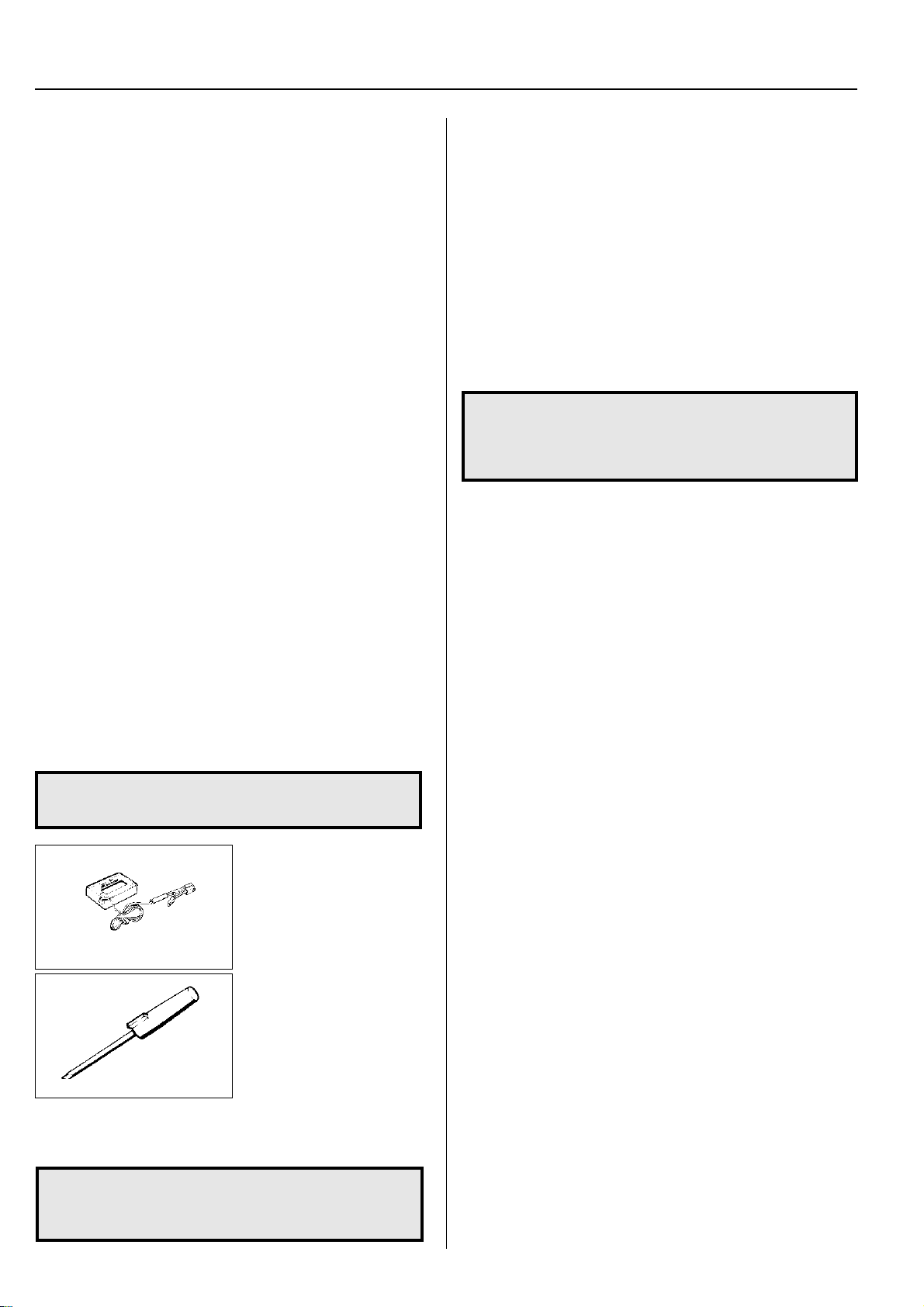
For Husqvarna Parts Call 606-678-9623 or 606-561-4983
3
Fine adjustment
Fine adjustment of the carburettor should be carried out after the
engine has been ”run-in”.
● The air filter should be clean and the cylinder cover fitted
when adjustments are made.
First adjust the L needle, then the H needle and finally the
idling speed's T -screw .
The following speed recommendations apply:
Idling speed = 2,500 rpm.
Fuel system
Max speed
Model During running in After running in
265 10,900 11,500
252, 250 RX (R) 12,900 (11,900) 13,500 (12,500)
240 11,900 12,500
245 11,900 12,500
225 10,500 11,000
232 10,300 10,800
235 10.500 11,000
240 RBD 10,500 11,000
322, 325 12,500 12,500
122 10,800
32 7,000
Mondo 9,000
Mega / Max 9,000
250PS 11,000 11,500
235 P — —
225 H60 / H75 10,500 11,000
18H 9,500 10,000
132HBV 7,100 7,600
140B / 141B
225HBV 7,700 8,200
NOTE!
The max. recommended speed must not be exceeded.
Low speed needle L
Find the highest idling speed by slowly turning the low speed
needle clockwise and anticlockwise. When the highest speed has
been found, turn the L needle 1/4 turn anticlockwise.
High speed needle H
The high speed needle H affects the engine's power and speed.
A too lean H needle setting (H needle screwed in too far) gives too
little fuel to the engine resulting in damage to the engine.
Run the engine at full throttle for about 10 seconds. The H needle
is set correctly when the engine ”splatters” a little.
If the muffler smokes heavily, at the same time as the engine
splatters a great deal the setting is too rich. Turn the H needle
clockwise until you find the setting that sounds right.
NOTE!
A tachometer should always be used to find the optimal
setting.
The recommended max. speed must not be exceeded.
Idling speed T-screw
Let the engine idle for about 30 seconds or until the speed has
stabilised. Adjust the idling speed T-screw until the engine idles
without stopping.
● Turn the screw clockwise if the engine stops.
● Turn the speed anticlockwise to lower the speed.
Correctly adjusted carburettor
A correctly adjusted carburettor means that the engine accelerates without hesitation and it 4 strokes a little at full throttle.
● A too lean adjusted L needle can cause starting difficulties
and bad acceleration.
● A too lean adjusted H needle results in lower power, bad
acceleration and/or damage to the engine.
● A too rich setting of the "L" and "H" needles give acceleration
problems or a too low working speed.
The max. recommended
speed must not be exceeded.
When checking the speed on
a trimmer no part of the cord
should be extended.
502 71 14-01
501 60 02-02
NOTE!
If the cutting equipment rotates while idling the T-screw
should be turned anticlockwise until it stops.
64
Check the speed using the
tachometer 502 71 14-01.
● Carefully screw in (clockwise) the L and H needles
until they bottom. Screw
out (anticlockwise) the
needle 1 turn. The carburettor is now set H = 1 and
L = 1. Use the special
screwdriver 501 60 02-02.
● Start the engine and run
warm for 10 minutes.
www.mymowerparts.com
Page 66
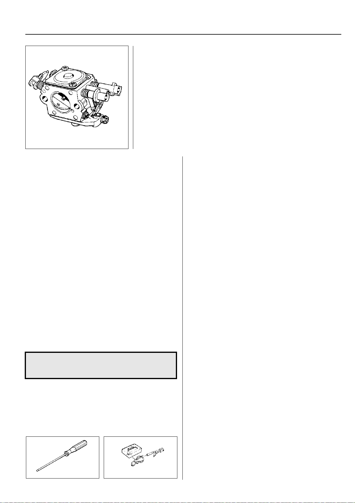
For Husqvarna Parts Call 606-678-9623 or 606-561-4983
Fuel system
Carburettors in E-TECH and CARB-EPA designs
(CARB-EPA only applies to USA)
On these types of carburettor the H and L needles can be adjusted within extremely
tight limits, to among others, comply with the stringent demands with regard to the
hydrocarbon and nitrogen oxide content in the exhaust fumes.
The carburettor needles on these carburettors are fitted with plastic sleeves with
movement limiters
To carry out adjustment when replacing needles or the entire carburettor the engine
must be under load. This is achieved by fitting a T rimmy Fix with the specified length and
diameter of trimmer cord. Consequently , the stated speed will be much lower that with
"normal" carburettor adjustment when the motor may run freely.
After replacing the needles or the entire carburettor on a CARB-EP A approved engine,
adjustment must be carried out according to the instructions below.
The combiguard or trim guard must be fitted when adjusting the H-needle.
After replacing the complete
carburettor
1. Check that the plastic sleeve on the H needle is turned as far
as possible anticlockwise (richest fuel mixture). The sleeve
sits freely on the needle and can be turned without affecting
the needle's setting.
Do not change the L needle setting. This is adjusted at the
factory and the plastic sleeve is already fixed on the needle.
2. Fit four trimmer cords Ø 3.3 mm on a Trimmy Fix.
(Trimmy Fix M10, 531 00 38-69 for models 225, 232, 322L,
322R, 325L, 325L-X, 325R-X. Trimmy Fix M12, 502 13 87-02
for model 235).
Maybe the hole needs to be enlarged a little to make fitting the
trimmer cords easier.
(Does not apply to Models 225H60/H75).
3. Cut the trimmer cord to the right length (measure the length
to the edge of the Trimmy Fix).
Model 225: 145 mm
Model 232: 155 mm
Model 235: 170 mm
Models 322L/R, 325L/L-X/R-X: 142 mm
Montera Trimmy Fix på maskinen.
Model 322C must be run with Trimmy Hit VI and its standard cord
(Ø 2.0 mm). Cut off the cord ends so that they are 146 mm long.
(Does not apply to model 225H60/H75 and 18H).
NOTE!
The spray guard must be removed from model 235.
Exercise care when the trimmer cord is rotating.
4. Start the engine. Adjust the idling speed T screw if necessary .
5. Use screwdriver 531 00 48-63 to adjust the H needle. The
blade is 2 mm wide and goes through the plastic sleeve and
only adjusts the needle.
Adjust the H needle so that the max. speed 8400 ± 200 rpm is set.
Use the tachometer 502 71 14-01 to check the speed.
(Does not apply to model 225H60/H75 and 18H).
531 00 48-63
502 71 14-01
3
6. Run the engine warm for 2–3 minutes.
7. Check that the max speed is still 8400 ± 200 rpm. Adjust the
H needle if necessary.
8. Check that the plastic sleeve on the H needle is still turned as
far as possible anticlockwise (richest fuel mixture).
9. Press in the plastic sleeve using a punch (Ø 5 mm).
The basic setting of the carburettor is now complete. Further fine
adjustment, within the limits that the plastic sleeves on the needles
permit, can be necessary.
Deviations for models 225H60/H75, 18H:
5A. Adjust the H needle until the max speed is reached.
Then turn the needle anticlockwise until the speed drops by
500 rpm.
6A. Run the engine warm at full throttle for 2–3 min.
7A. Check the idling speed and that the engine reacts quickly
when accelerating.
7B. Adjust the H needle so that the max. speed is reached. Then turn
the needle anticlockwise until the speed drops by 500 rpm.
After replacing only the H needle
1. Turn the L needle as far as possible anticlockwise (richest fuel
mixture).
2. Remove the plastic sleeve on the H needle and unscrew the
needle.
3. Carefully screw the new H-needle to the bottom and then
loosen it 1/2 turn. On model 322/325 the needle should be
loosened approx. 2 1/2 turns.
4. Press a new plastic sleeve on the H needle down to the first
stop. The sleeve can now be turned without turning the needle.
5. Turn the plastic sleeve as far as possible anticlockwise (richest
fuel mixture) without turning the needle.
6. Fit four trimmer cords Ø 3.3 mm on a Trimmy Fix.
(Trimmy Fix M10, 531 00 38-69 for models 225, 232, 322L,
322R, 325L, 325L-X, 325R-X. Trimmy Fix M12, 502 13 87-02
for model 235).
Maybe the hole needs to be enlarged a little to make fitting the
trimmer cords easier.
(Does not apply to model 225H60/H75 and 18H).
7. Cut the trimmer cord to the right length (measure the length to
the edge of the Trimmy Fix).
Model 225: 145 mm Model 232: 155 mm
Model 235: 170 mm Models 322L/R, 325L/L-X/R-X: 142 mm
Fit the Trimmy Fix on the machine.
Model 322C must be run with Trimmy Hit VI and its standard cord
(Ø 2.0 mm). Cut off the cord ends so that they are 146 mm long.
(Does not apply to model 225H60/H75 and 18H).
www.mymowerparts.com
65
Page 67
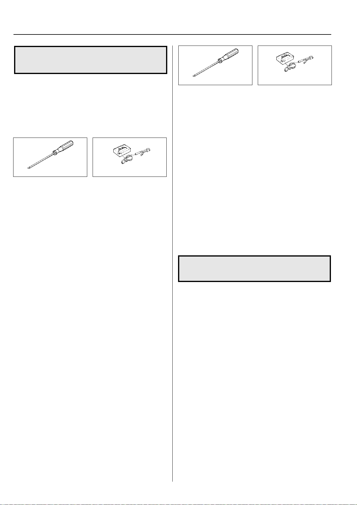
For Husqvarna Parts Call 606-678-9623 or 606-561-4983
3
NOTE!
The spray guard must be removed from model 235.
Exercise care when the trimmer cord is rotating.
8. Start the engine. Adjust the idling speed T screw if necessary.
9. Use screwdriver 531 00 48-63 to adjust the H needle. The
blade is 2 mm wide and goes through the plastic sleeve and
only adjusts the needle.
Adjust the H needle so that the max. speed 8400 ± 200 rpm
is set.
Use the tachometer 502 71 14-01 to check the speed.
(Does not apply to model 225H60/H75 and 18H).
531 00 48-63
10.Run the engine warm for 2–3 minutes.
11.Check that the max speed is still 8400 ± 200 rpm. Adjust the
H needle if necessary.
12.Check that the plastic sleeve on the H needle is still turned as
far as possible anticlockwise (richest fuel mixture).
13.Press in the plastic sleeve using a punch (Ø 5 mm).
The basic setting of the carburettor is now complete. Further fine
adjustment, within the limits that the plastic sleeves on the
needles permit, can be necessary.
Deviations for models 225H60/H75, 18H:
9A. Adjust the H needle until the max speed is reached.
Then turn the needle anticlockwise until the speed drops by
500 rpm.
10A.Run the engine warm at full throttle for 2–3 min.
11A. Check the idling speed and that the engine reacts quickly
when accelerating.
11B.Adjust the H needle so that the max. speed is reached. Then
turn the needle anticlockwise until the speed drops by 500 rpm.
502 71 14-01
Fuel system
After replacing the H and L needles
1. Remove the plastic sleeves from both needles and screw out
the needles.
2. Carefully screw the new needles in until they bottom.
Now screw out the L-needle 2 turns. On models 322/325 the
needle should be screwed out approx. 1 turn.
Now screw out the H-needle 1/2 turns. On models 322/325 the
needle should be screwed out approx. 2 1/2 turns.
3. Press the new plastic sleeves on the needles until the first stop.
The sleeves can still be turned without the needles turning.
4. Turn the plastic sleeve on the L needle as far as possible
clockwise (leanest fuel mixture).
5. Start the engine and let it idle.
6. Use the screwdriver 531 00 48-63 to adjust the L needle. The
blade is 2 mm wide and goes through the plastic sleeve and
only adjusts the needle.
Adjust the L needle so that the highest idling speed is obtained.
Use the tachometer 502 71 14-01 to check the speed.
7. Check that the plastic sleeve on the L needle is still turned as
far as possible clockwise (leanest fuel mixture).
531 00 48-63
8. Press the plastic sleeve on the L needle using a punch
(Ø 5 mm).
Now turn the L needle as far as possible anticlockwise (richest
fuel mixture).
9. Turn the plastic sleeve on the H needle as far as possible
anticlockwise (richest fuel mixture).
10.Fit four trimmer cords Ø 3.3 mm on a Trimmy Fix.
(Trimmy Fix M10, 531 00 38-69 for models 225, 232, 322L,
322R, 325L, 325L-X, 325R-X. Trimmy Fix M12, 502 13 87-02
for model 235).
Maybe the hole needs to be enlarged a little to make fitting the
trimmer cords easier.
(Does not apply to model 225H60/H75 and 18H).
11.Cut the trimmer cord to the right length (measure the length to
the edge of the Trimmy Fix).
Model 225: 145 mm Model 232: 155 mm
Model 235: 170 mm
Model 322L/R, 325L/L-X/R-X: 142 mm
Fit the Trimmy Fix on the machine.
Model 322C must be run with Trimmy Hit VI and its standard cord
(Ø 2.0 mm). Cut off the cord ends so that they are 146 mm long.
(Does not apply to model 225H60/H75 and 18H).
NOTE!
The spray guard must be removed from model 235.
Exercise care when the trimmer cord is rotating.
12.Start the engine. Adjust the idling speed T screw if necessary .
13. Use screwdriver 531 00 48-63 to adjust the H needle. The
blade is 2 mm wide and goes through the plastic sleeve and
only adjusts the needle.
Adjust the H needle so that the max. speed 8400 ± 200 rpm
is set.
Use the tachometer 502 71 14-01 to check the speed.
(Does not apply to model 225H60/H75).
14.Run the engine warm for 2–3 minutes.
15.Check that the max speed is still 8400 ± 200 rpm. Adjust the
H needle if necessary.
16.Check that the plastic sleeve on the H needle is still turned
anticlockwise as far as possible (richest fuel mixture).
17.Press in the plastic sleeve using a punch (Ø 5 mm).
The basic setting of the carburettor is now complete. Further fine
adjustment, within the limits that the plastic sleeves on the
needles permit, can be necessary.
Deviations for models 225H60/H75, 18H:
13A. Adjust the H needle until the max speed is reached.
Then turn the needle anticlockwise until the speed drops by
500 rpm.
14A.Run the engine warm at full throttle for 2–3 min.
15A. Check the idling speed and that the engine reacts quickly
when accelerating.
15B.Adjust the H needle so that the max. speed is reached. Then
turn the needle anticlockwise until the speed drops by 500 rpm.
502 71 14-01
66
www.mymowerparts.com
Page 68
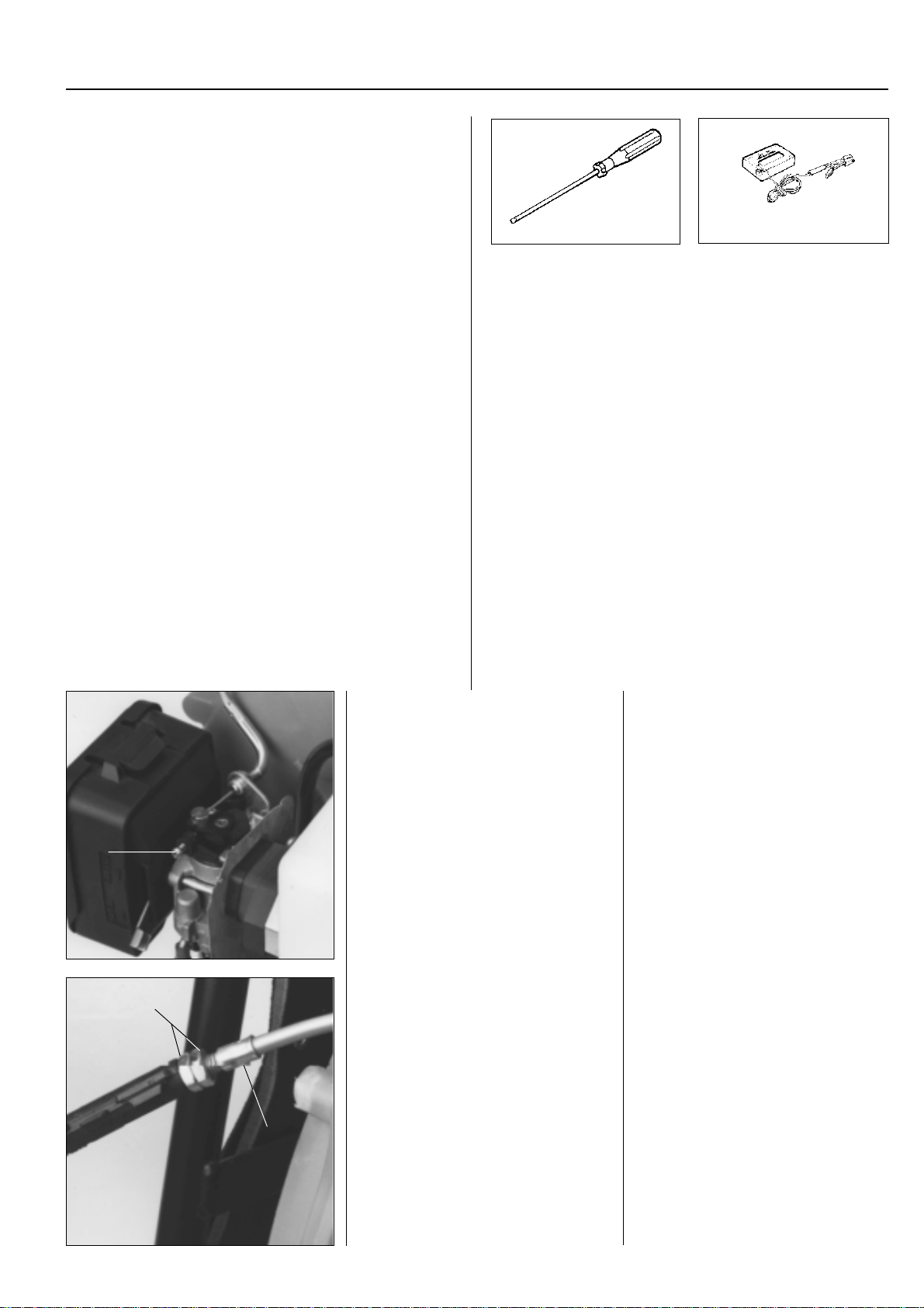
For Husqvarna Parts Call 606-678-9623 or 606-561-4983
Fuel system
Replacing only the L needle
1. Turn the H needle as far as possible clockwise (leanest fuel
mixture).
2. Remove the plastic sleeve on the L needle and unscrew the
needle.
3. Carefully screw the new L-needle to the bottom and then
loosen it 2 turns. On models 322/325 unscrew the needle 1
turn.
4. Press a new plastic sleeve on the L needle down to the first
stop. The sleeve can now be turned without turning the
needle.
5. Turn the plastic sleeve as far as possible clockwise (leanest
fuel mixture).
6. Start the engine and let it idle.
7. Use the screwdriver 531 00 48-63 to adjust the L needle. The
blade is 2 mm wide and goes through the plastic sleeve and
only adjusts the needle.
Adjust the L needle so that the highest idling speed is
obtained.
Use the tachometer 502 71 14-01 to check the speed.
3
531 00 48-63
8. Check that the plastic sleeve on the L needle is still turned as
far as possible clockwise (leanest fuel mixture).
9. Press the plastic sleeve on the L needle using a punch
(Ø 5 mm).
The basic setting of the carburettor is now complete. Further fine
adjustment, within the limits that the plastic sleeves on the
needles permit, can be necessary.
502 71 14-01
Model 141B
Only the idling speed can be adjusted on
this model.
The idling speed should be approx. 2,500
rpm.
A
Check that the throttle cable has 0.5 – 1
A
B
mm of play.
Model 141B
The carburettor on this model has no
adjustable needles.
Only the idling speed can be adjusted
with screw (A).
The right speed is approx. 2,500 rpm
Adjust the idling speed when the engine
is warm and has a clean air filter.
When the throttle is in the idling position
the throttle cable must have 0.5 – 1 mm of
play .
Adjust the play by first loosening both
locking nuts (A) and then turning the
adjuster screw (B). The play is increased
when the screw is screwed inwards and
decreases when screwed outwards.
Tighten the locking nuts against each
other after adjusting.
www.mymowerparts.com
67
Page 69
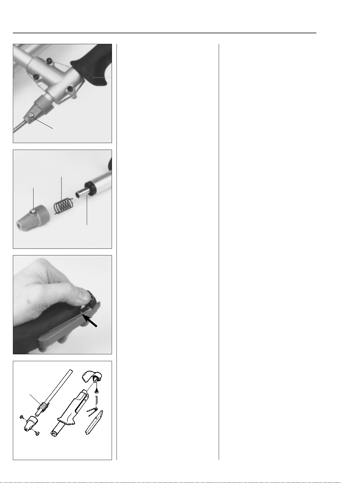
For Husqvarna Parts Call 606-678-9623 or 606-561-4983
3
Fuel system
Throttle
Model 265
Dismantle the throttle cable.
Lift off the throttle.
A
Loosen the locking screw (B) and dismantle the throttle.
C
B
Throttle
Model 265
Loosen the locking screw (A) and pull out
the throttle cable.
Remove the three screws that hold the
throttle on the handle and lift off the grip
and the two clamp halves.
Loosen the locking screw (B).
The return spring (C) is now accessible
and the throttle control (D) with its shaft
can be pulled from the throttle.
D
Press out the bearing pin from the throttle
lock using a punch.
Replace damaged parts and reassemble
in the reverse order set out for dismantling.
Reassembly of the throttle takes place in
the reverse order set out for dismantling.
C
Fold back the rubber handle and press
out the bearing pin using a punch.
The spring and throttle lock are now accessible for replacement.
Reassembly of the throttle takes place in
the reverse order set out for dismantling.
Tension the spring (C) about 1/4 – 1/2
turn.
68
www.mymowerparts.com
Page 70
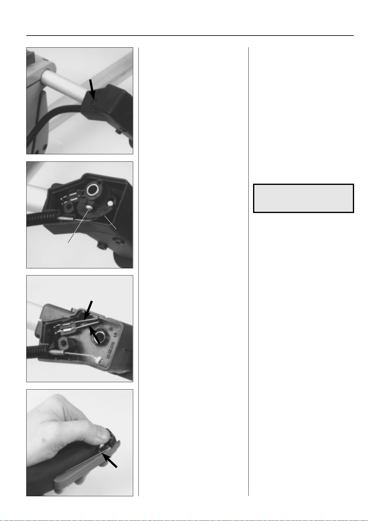
For Husqvarna Parts Call 606-678-9623 or 606-561-4983
Fuel system
Model 250
Remove the screw and cover.
Loosen the screw (A) and lift out the
connection piece (B) and the return spring.
3
Model 250
Fold down the handle for better accessibility.
Remove the screw and cover over the
throttle cable's and the short circuit cable's connection in the handle.
Loosen the screw (A) and lift out the
throttle cable's connection piece (B) and
the return spring.
NOTE!
There is some tension on the
spring.
The throttle's shaft can now be removed
B
A
Dismantle the short circuit cable's contact strips for inspection and possible
replacement.
Press out the bearing pin from the throttle
lock using a punch.
Replace damaged parts and reassemble
in the reverse order set out for dismantling.
for replacement.
Lift out the short circuit cable's contact
strips using flat nose pliers.
Check the contact surface on the strips
replace or clean them if they are corroded
or burnt.
Fold back the rubber handle and press
out the bearing pin using a punch.
The spring and throttle lock are now accessible for replacement.
www.mymowerparts.com
69
Page 71
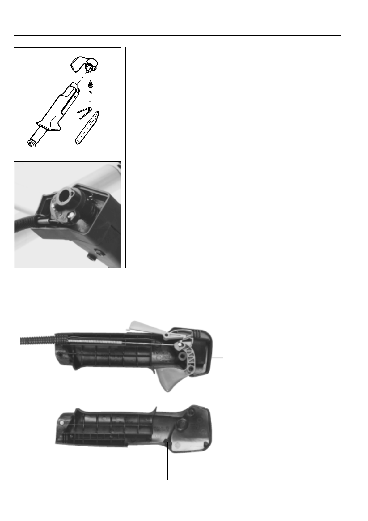
For Husqvarna Parts Call 606-678-9623 or 606-561-4983
3
Fuel system
Reassembly of the throttle takes place in
the reverse order set out for dismantling.
● Lubricate the throttle control shaft with a little grease and slide it in the bearing
housing.
● Position the return spring and check that it enters the hole in the bearing housing.
● Place the throttle cable's connection piece in position and also check here that the
spring enters the hole.
● Connect the throttle cable.
● Press the throttle cable's connection piece down over the shaft.
● Make sure the throttle is in the idling position.
● Tension the throttle cable by turning the connection piece to the position when the
throttle valve just starts to move.
● Tighten the screw and check that the throttle also functions as intended in the stop
position.
Reassembly of the throttle takes place in
the reverse order set out for dismantling.
Lubricate with a little grease, preferably
cold resistant.
Models 225HBV, 225R, 232R,
235R, 245R, 250R
Dismantle the throttle from the handle
B
and remove the screws that hold together
the two halves of the throttle grip.
Carefully separate the two halves.
Replace any damaged parts.
Check when reassembling that the guide
pin (A) enters the hole in the throttle lock
(B), and that the lock functions without
jamming when both throttle halves have
been screwed together.
70
A
www.mymowerparts.com
Page 72
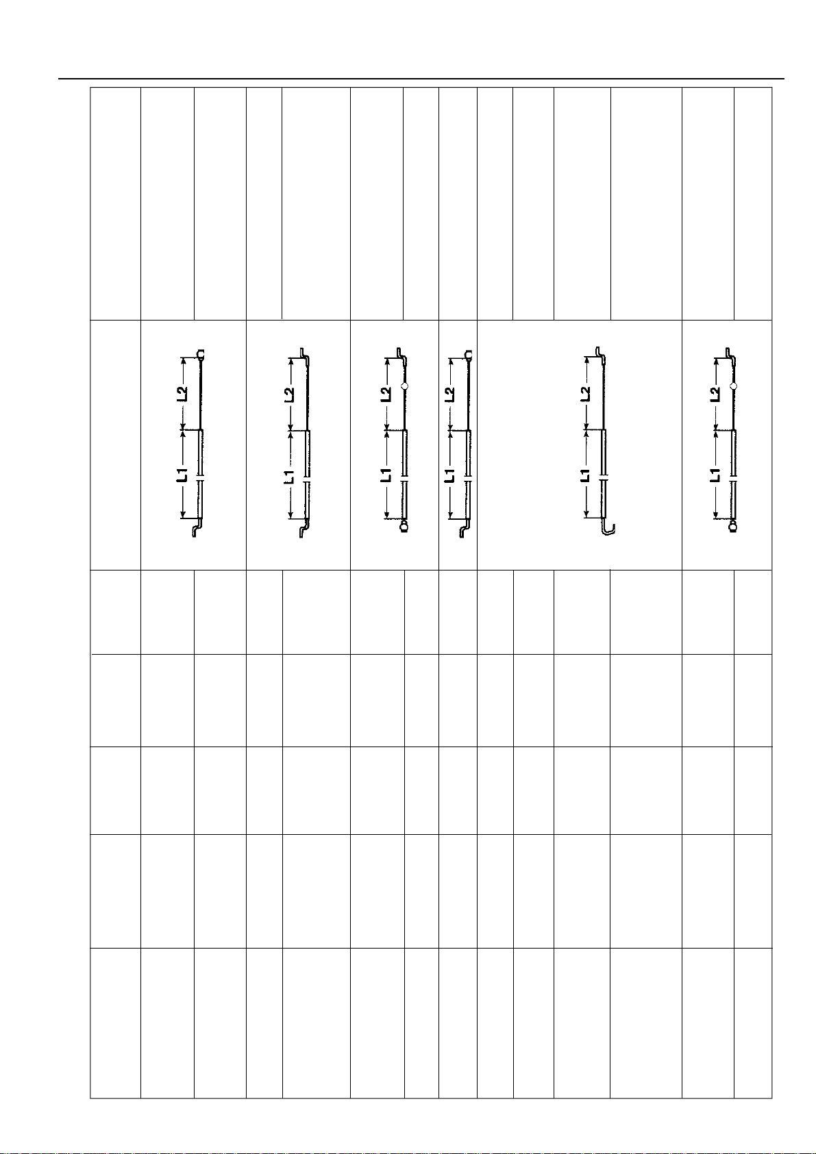
For Husqvarna Parts Call 606-678-9623 or 606-561-4983
Fuel system
The throttle cable runs under the
engine. Steel casing.
Steel casing on cables replaced by
502 27 93-03.
Brown T eflon casing.
Brown Teflon casing. The cable
runs through the crankcase. Replaced
by 537 03 71-02 and 537 02 42-02
Black plastic casing. Cable Ø 0.9.
Kit with air filter holder and rubber bellows.
Black plastic casing. Cable Ø 0.9.
Steel casing replaced by 502 28 60-03.
Teflon casing.
Teflon casing. Cable Ø 0.9.
the crankcase. Replaced by 502 28 60-05.
the crankcase. Cable Ø 0.9. Replaced
by 537 03 71-01 and 537 02 42-01.
3
plastic casing. Cable Ø 0.9. Kit with
air filter holder and rubber bellows.
plastic casing. Cable Ø 0.9.
Throttle cable
mm
mm protrude
Model Order no. L1 casing L2 cable Serial no. Nipples Remarks
250R – 1993 502 27 29-01 1000 ±5 120 ±1 Index finger throttle 502 28 06-01.
250R 1994 – 502 27 29-06 965 ±5 162 ±1 Index finger throttle 502 28 06-01.
250R – 1996 502 27 93-03 965 ±2 152 ±1 >6520029 Index finger throttle 502 28 06-01.
250R 1997 – 502 27 93-04 640 ±2 115 ±1 >7180059 Index finger throttle 502 28 06-01.
www.mymowerparts.com
250R 1998 – 537 03 71-02 640 ±2 115 ±1 >8500001 Index finger throttle 502 28 06-01.
250R 1998 – 537 02 42-02 640 ±2 115 ±1 >8500001 Index finger throttle 502 28 06-01.
250RX 1995– 502 27 29-07 795 ±5 133 ±1 Thumb throttle 502 28 37-01.
250RX 1996 – 502 28 60-03 810 ±2 116 ±1 >6450153 Thumb throttle 502 28 37-01. Brown
250RX – 1997 502 28 60-06 810 ±2 116 ±1 Thumb throttle 502 28 37-01. Brown
250RX 1997 – 502 28 60-04 840 ±2 80 ±1 >7170157 Thumb throttle 502 28 37-01. Brown
252RX 1997 – Teflon casing. The cable runs through
250RX 1997– 502 28 60-05 840 ±2 80 ±1 >7420190 Thumb throttle 502 28 37-01. Brown
252RX 1997 – >7430001 Teflon casing. The cable runs through
252RX 1998 – 537 03 71-01 840 ±2 80 ±1 >8450073 Thumb throttle 502 28 37-01. Black
252RX 1998 – 537 02 42-01 840 ±2 80 ±1 >8450073 Thumb throttle 502 28 37-01. Black
71
Page 73
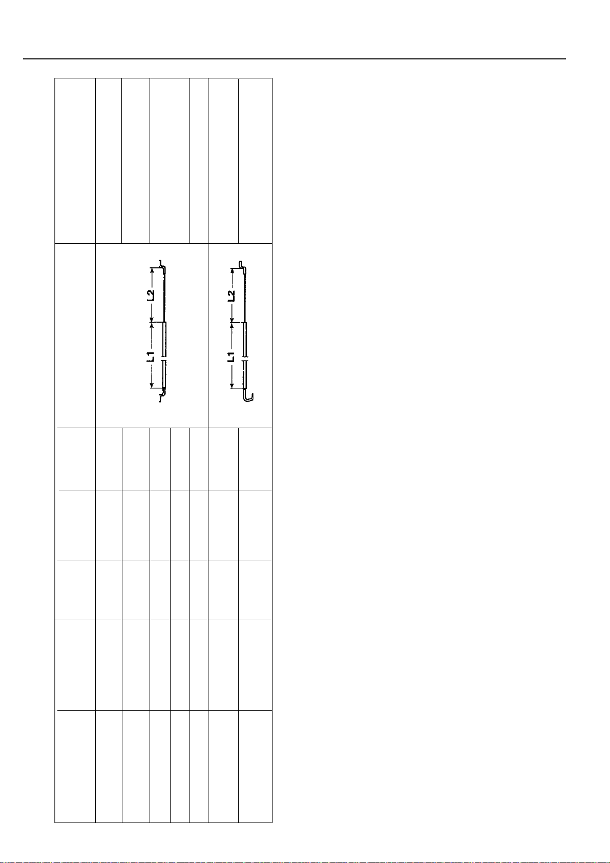
For Husqvarna Parts Call 606-678-9623 or 606-561-4983
3
502 12 18-03
Fuel system
T eflon casing. Replaced by 502 28 60-0 8.
Teflon casing. Cable Ø 0.9.
Throttle cable
mm
mm protrude
72
Model Order no. L1 casing L2 cable Serial no. Nipples Remarks
39R – 1988 502 11 82-01 916 ±1 67 ±5 Index finger throttle 502 12 18-03
240/245R – 1994 502 11 82-01 916 ±1 67 ±5 Index finger throttle with throttle lock
240/245R 1994 – 502 27 93-01 895 ±2 95 ±1 >4110001 Index finger throttle 502 28 06-01
245RX – 1994 502 11 82-02 792 ±1 67 ±5 Index finger throttle 502 12 18-03
245RX 1994 – 502 27 93-02 795 ±2 97 ±1 >411001 Index finger throttle 502 28 06-01
245RX 1995 – 502 28 60-01 700 ±2 61 ±1 >5510267 Thumb throttle 502 28 37-01. Brown
www.mymowerparts.com
245RX 1997 – 502 28 60-08 700 ±2 61 ±1 Thumb throttle 502 28 37-01. Brown
Page 74
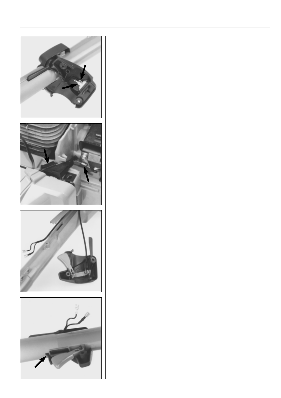
For Husqvarna Parts Call 606-678-9623 or 606-561-4983
Fuel system
Models 225 L, E, 232 L
Remove the screws.
Disconnect the cables from the stop
switch.
Unhook the throttle cable from the carburettor.
3
Models 225 L, E, 232 L
Remove both the screws that hold the
throttle halves together.
Fold back the right half and disconnect
the cables from the stop switch.
Lift up the plastic guide and unhook the
throttle cable from the carburettor.
Inspect the different parts with regard to
wear and damage.
Replace damaged components.
Reassemble the throttle in the reverse
order set out for dismantling.
Check that it functions, especially the
throttle lock.
Fold back the left half of the throttle.
The different parts are now easily acces-
sible for service or replacement.
Reassemble the throttle in the reverse
order set out for dismantling.
Note the following:
●
Check that the throttle cable and short
circuit cable are not crushed.
●
The cable rail should be under the
throttle control.
●
The pin in the throttle control's left half
goes in the hole on the under side of
the shaft.
www.mymowerparts.com
73
Page 75
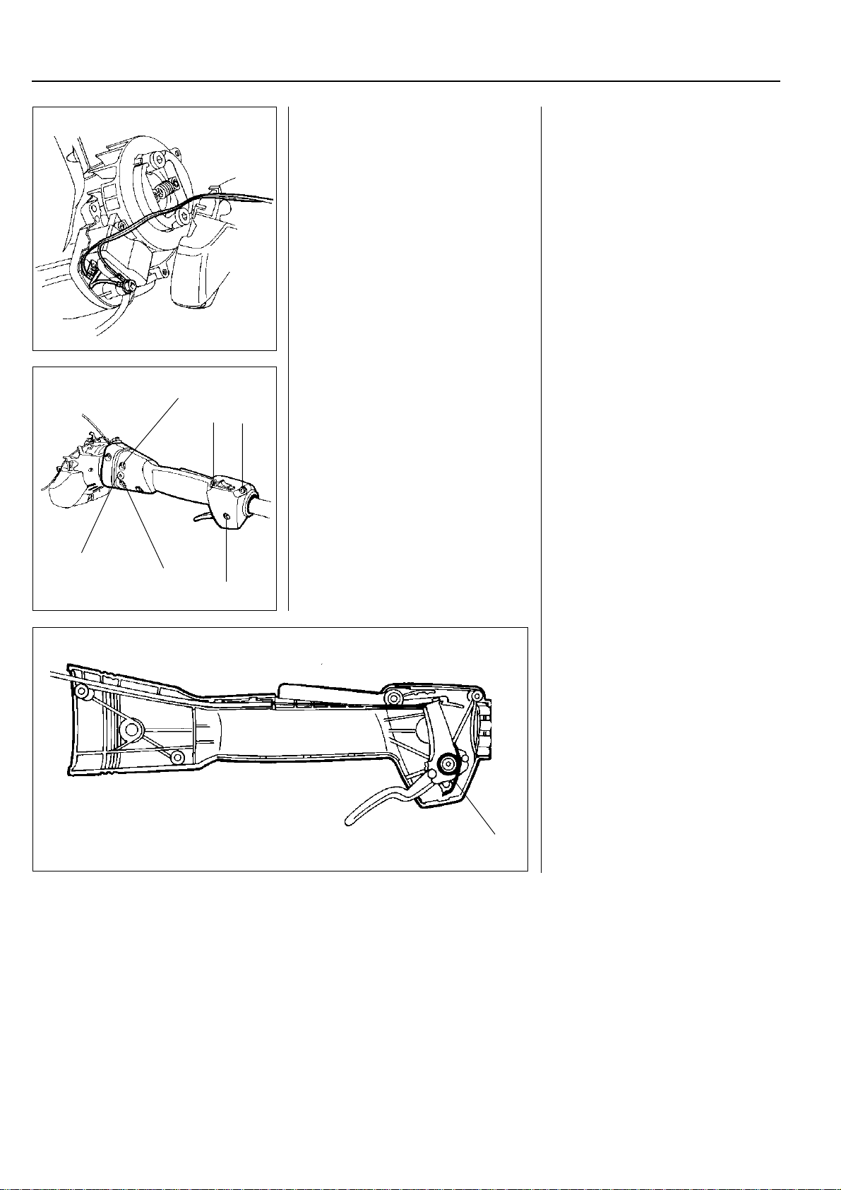
For Husqvarna Parts Call 606-678-9623 or 606-561-4983
3
Fuel system
Models 322, 325
Separate the engine body and the clutch
cover.
Pull away the shaft with the throttle from
B
C
C
the clutch cover.
Remove the throttle from the shaft.
Models 322, 325
We recommend that the throttle is dismantled from the engine and shaft in
order to efficiently carry out service and
repair work.
Separate the engine body and the clutch
cover (see chapter "Ignition system").
Remove both screws (A) (one on each
side).
Loosen the screws (B) and pull off the
shaft with the throttle from the clutch
cover.
Loosen the 3 front screws (C) (approx. 2
turns) holding the throttle halves and pull
the throttle off of the shaft.
A
B
C
Remove the screws holding the throttle
together and carefully separate the halves.
Note how the different parts are fitted.
Pay special attention to which way the
return spring (A) faces.
The stop contact can be pried back using
a small screwdriver if it needs to be replaced.
A
74
www.mymowerparts.com
Page 76
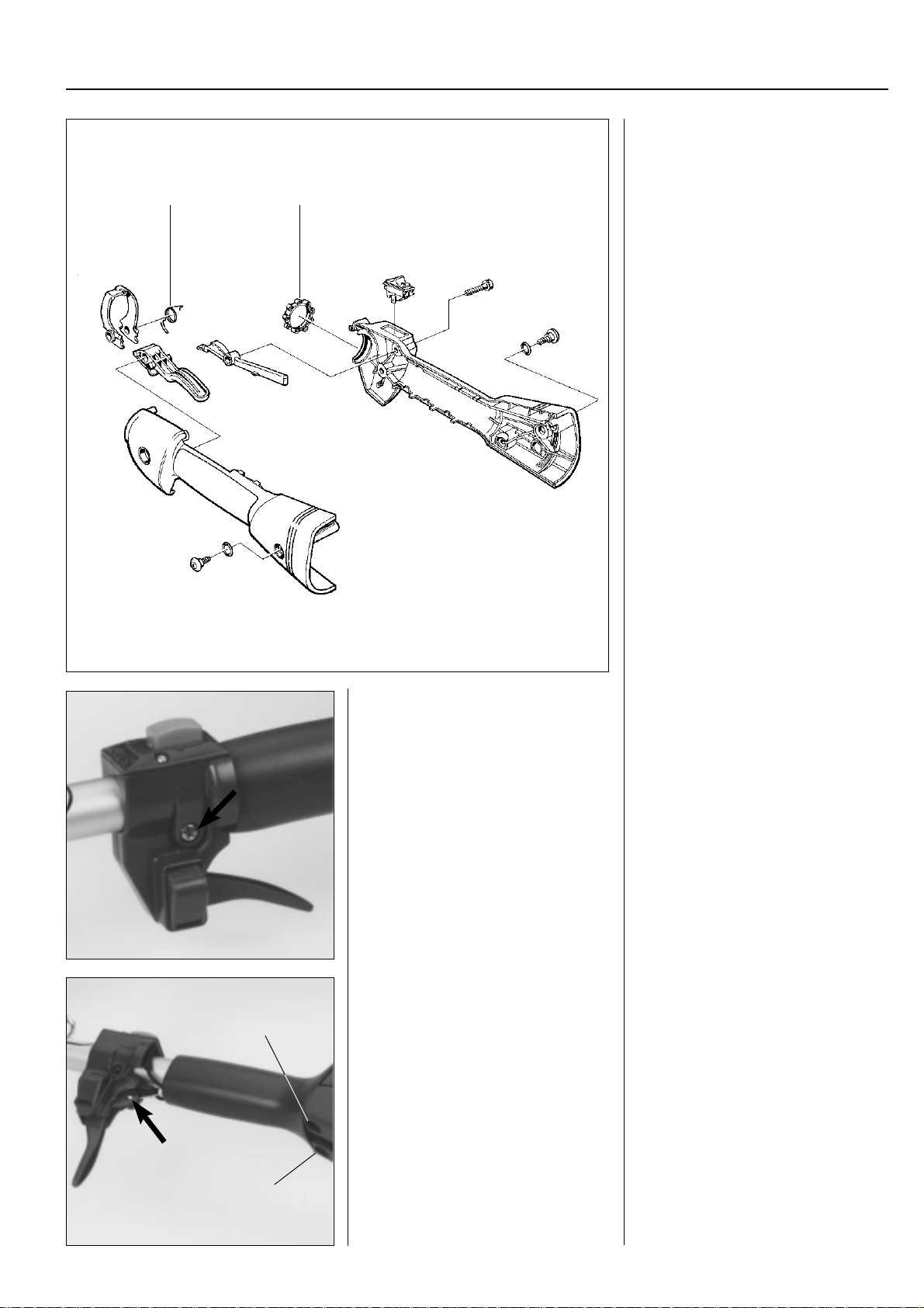
For Husqvarna Parts Call 606-678-9623 or 606-561-4983
Fuel system
Assembly of the throttle is done in the
reverse order as set out for dismantling.
Position the parts in the left-hand throttle
A
B
half.
Ensure the return spring (A) is facing the
right way .
Check that the throttle cable and the
short-circuit cable are pressed correctly
down in their channels so that they are
not pinched when the two throttle halves
are screwed together.
Do not forget to put the vibration element
(B) in position before the throttle halves
are put together. Lubricate the vibration
element with soapy water. This facilitates
fitting the throttle on the shaft.
Fit together the throttle halves using the 5
screws, but do not tighten them fully before the throttle has been positioned on
the shaft.
Assemble the remaining parts in the reverse order as set out for dismantling.
3
Models 122/32/Mondo
Remove the screw and slide the throttle
forward until the throttle cable is accessible.
Remove the throttle cable.
The shaft and engine body must be sepa-
A
rated to replace the throttle.
Models 122/32/Mondo
Remove the screw that holds throttle on
the shaft and slide the throttle forward
until the throttle cable is accessible.
Remove the throttle cable, replace if necessary.
The shaft and engine body must be separated if the entire throttle is to be replaced.
Loosen the screw/screws (A) and remove
the short circuit cable.
Remove the handle. It is easier if soap is
used as a slip agent.
A
www.mymowerparts.com
75
Page 77
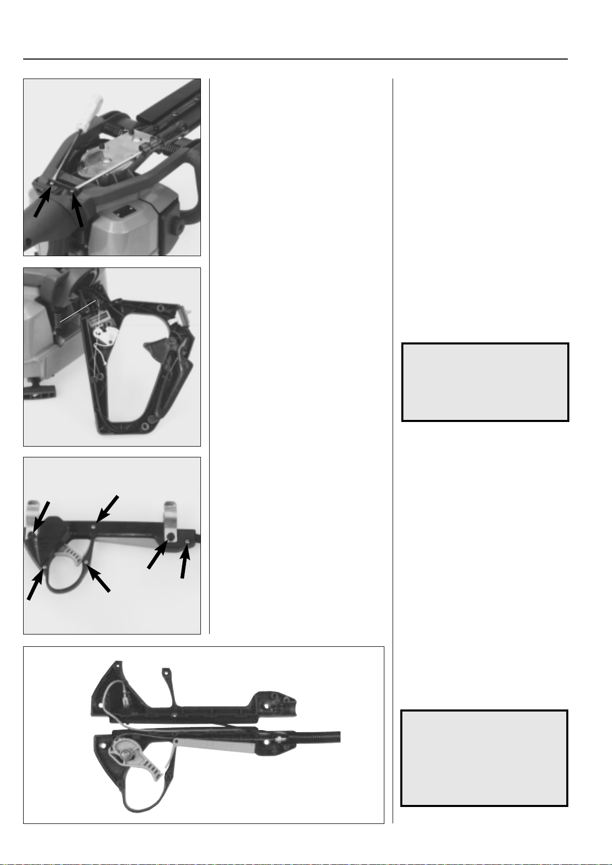
For Husqvarna Parts Call 606-678-9623 or 606-561-4983
3
Fuel system
Models 225 H 60, 225 H 75
Remove the locking plate and pull out the
rear handle from the handlebars.
Separate the two handle halves and inspect the different components for wear,
replace if necessary.
Reassemble in the reverse order set out
A
for dismantling.
Models 225 H 60, 225 H 75
Remove the locking plate by prising it
upwards using two screwdrivers.
Pull out the rear handle from the handlebars.
Remove the screws and carefully separate the two handle halves. All components are now easily accessible for possible replacement.
Reassemble in the reverse order set out
for dismantling.
Models 250PS, 235 P
Remove the screws and separate the
handle halves.
NOTE!
Ensure that the throttle cable
enters the cut-out (A) correctly
so that it is not crushed when the
other handle half is fitted.
Lubricate the O-ring with grease.
Models 250PS, 235 P
Remove all the screws and carefully separate the handle halves.
Inspect all parts with regard to wear and
damage. Replace damaged parts.
Reassemble in the reverse order set out
for dismantling.
76
NOTE!
Check that the short circuit cables
and throttle cable are not crushed.
The short circuit cables should be
routed outside of the handle
except at the rear and front
sections.
www.mymowerparts.com
Page 78
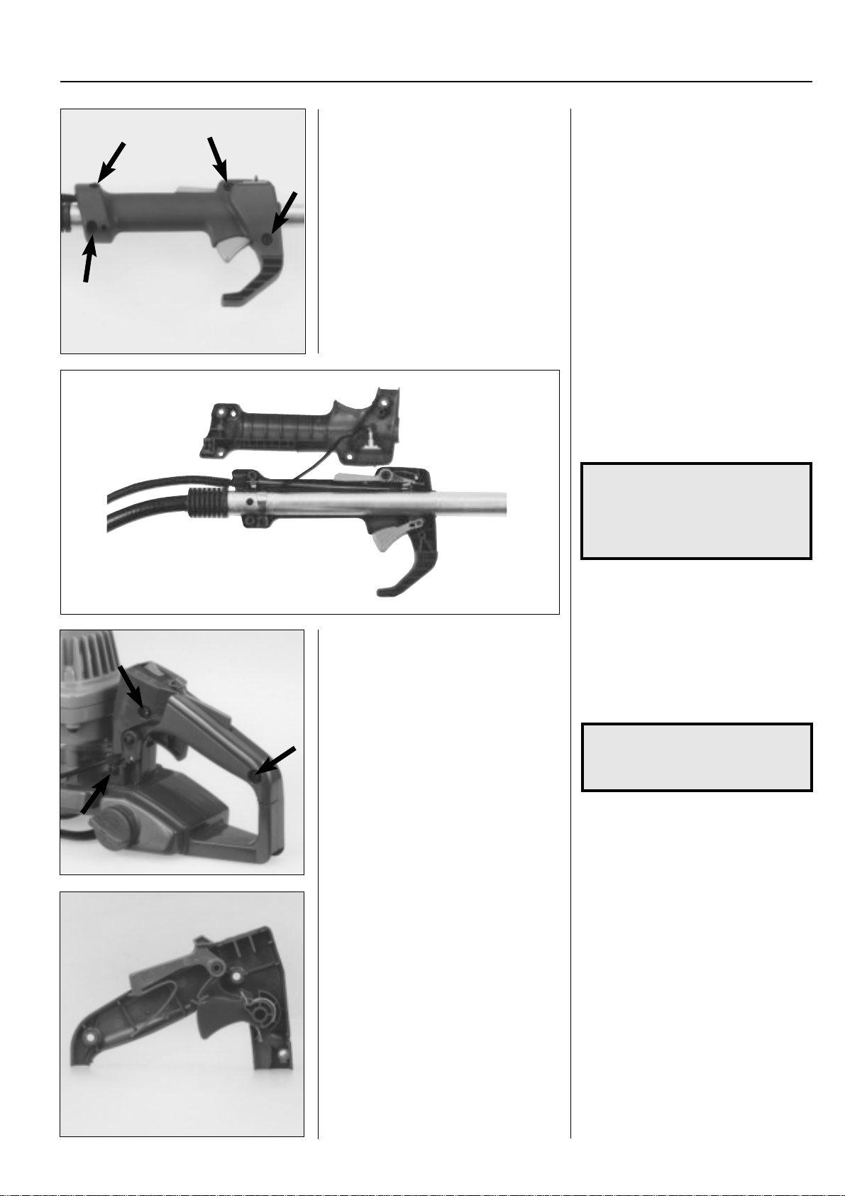
For Husqvarna Parts Call 606-678-9623 or 606-561-4983
Fuel system
Models 232 RBD, 240 RBD
Remove the screws and separate the
handle halves.
3
Models 232 RBD, 240 RBD
Remove the screws and separate the
handle halves.
Inspect all parts with regard to wear and
damage. Replace damaged parts.
Reassemble in the reverse order set out
for dismantling.
Model 18H
Remove the screws and lift off the handle
half.
NOTE!
Check that the short circuit cable
under
is
casing to prevent it from being
crushed.
Model 18H
Remove the screws and note how they
were placed, as they are of different
lengths.
Remove the handle half.
NOTE!
The lever arm for the throttle cable
does not need to be dismantled.
the throttle cable's
Inspect and replace worn or damaged
parts.
Assemble in the reverse order as set out
for dismantling.
www.mymowerparts.com
Inspect and replace worn or damaged
parts.
Assemble in the reverse order as set out
for dismantling.
77
Page 79
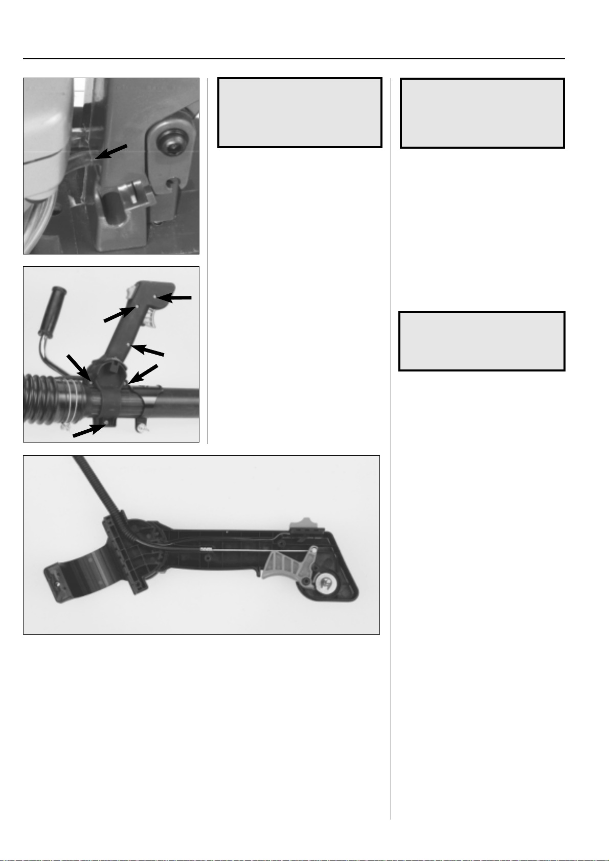
For Husqvarna Parts Call 606-678-9623 or 606-561-4983
3
Fuel system
NOTE!
Check that the fuel hose is not
pinched and that the stop contact
sits correctly.
Fit the throttle cable.
Model 141B
Remove the screws and separate the
handle halves.
NOTE!
Check that the fuel hose is not
pinched and that the stop contact
sits correctly.
Fit the throttle cable.
Model 141B
Remove the screws and separate the
handle halves.
NOTE!
The screw for angling the handle
does not need to be loosened or
removed.
Worn or damaged parts can be easily
replaced once the right-hand handle half
has been removed.
Check when assembling that the shortcircuit cable is not pinched between the
two handle halves.
78
www.mymowerparts.com
Page 80

For Husqvarna Parts Call 606-678-9623 or 606-561-4983
Technical data
Model Idling speed Max. speed Carburettor type Tank volume
Mondo
122L
Mondo Max
225L/LD
232L
Mondo Mega
225R/RD
232R / 235 R
322
325
240R
245R
250R
245RX
250RX
252RX
265RX
240RBD
235P
250PS
225E
18H
225H60/75
140B
141B
Fuel system
rpm rpm ◊ type setting * fuel, l
3,000 9,000 Walbro H = 2 0.48
WT 380 L = 2
3,000 10,800 Walbro – 0.40
WYL –
3,000 9,000 Walbro H = 2 0.48
WT 380 L = 2
2,700 11,000 – Walbro WT 235 H = 1 – 1 1/4 0.50
12,000 Walbro WT 270 L = 1 – 1 1/4
2,700 11,000– Walbro WT 235 H = 1 – 1 1/4 0.50
12,000 Walbro WT 270 L = 1 – 1 1/4
3,000 9,000 Walbro H = 2 0.46
WT 380 L = 2
2,700 11,000– Walbro WT 235 H = 1 – 1 1/4 0.50
12,000 Walbro WT 270 L = 1 – 1 1/4
2,700 11,000– Walbro WT 235 H = 1 – 1 1/4 0.50
12,000 Walbro WT 270 L = 1 – 1 1/4
2,500 12,500 Zama H = 2 0.50
EL 11 L = 1
2,500 12,500 Zama H = 2 0.50
EL 11 L = 1
2,700 12,500 Walbro H = 1 – 1 1/4 0.80
WT 99 L = 1 – 1 1/4
2,700 12,500 Walbro H = 1 – 1 1/4 0.80
WT 99 L = 1 – 1 1/4
2,700 12,500 Walbro HDA 86B H = 1 – 1 1/4 0.80
Walbro HDA 142 L = 1 – 1 1/4
2,700 12,500 Walbro H = 1 – 1 1/4 0.80
WT 99 L = 1 – 1 1/4
2,700 13,500 Walbro HDA 86B H = 1 – 1 1/4 0.80
Walbro HDA 142 L = 1 – 1 1/4
2,700 14,000 Walbro H = 1 – 1 1/4 0.80
HDA 142 L = 1 – 1 1/4
2,250 11,500 Tillotson H = 1 – 1 1/4 1.00
HS 121A L = 1 – 1 1/4
2,700 11,000– Walbro WT 235 H = 1 – 1 1/4 0.60
12,000 Walbro WT 270 L = 1 – 1 1/4
2,700 – Walbro WT 235 H = 3/4 – 1 0.50
Walbro WT 270 L = 3/4 – 1
2,500 11,500 Walbro HDA 86B H = 1 – 1 1/4 0.90
Walbro HDA 142 L = 1 – 1 1/4
2,700 11,000– Walbro H = 1 – 1 1/4 0.50
12,000 WT 270 L = 1 – 1 1/4
3,000 10,000 Walbro WT 379 H = 2 0.21
Zama CIU-W4 L = 2
2,700 11,000– Walbro WT 406 H = 1 – 1 1/4 0.40
12,000 Walbro WT 421 L = 1 – 1 1/4
2,500 Walbro HDA 110A H = 1 2.0
L = 1
2,500 Walbro WYK – 2.0
3
132HBV
225BV/225HBV
* Only basic setting. Applies to carburettor needles without plastic caps fitted.
◊ Do not exceed the stated max speed. Risk of engine damage. The figures apply to a run-in engine Reduce the speed by
600–700 rpm for an engine that has not been run-in.
2,500 7,600 Walbro 0.60
WT 141
2,500 8,200 Walbro WT 235 H = 1 – 1 1/4 0.40
Walbro WT 270 L = 1 – 1 1/4
www.mymowerparts.com
79
Page 81

For Husqvarna Parts Call 606-678-9623 or 606-561-4983
80
www.mymowerparts.com
Page 82
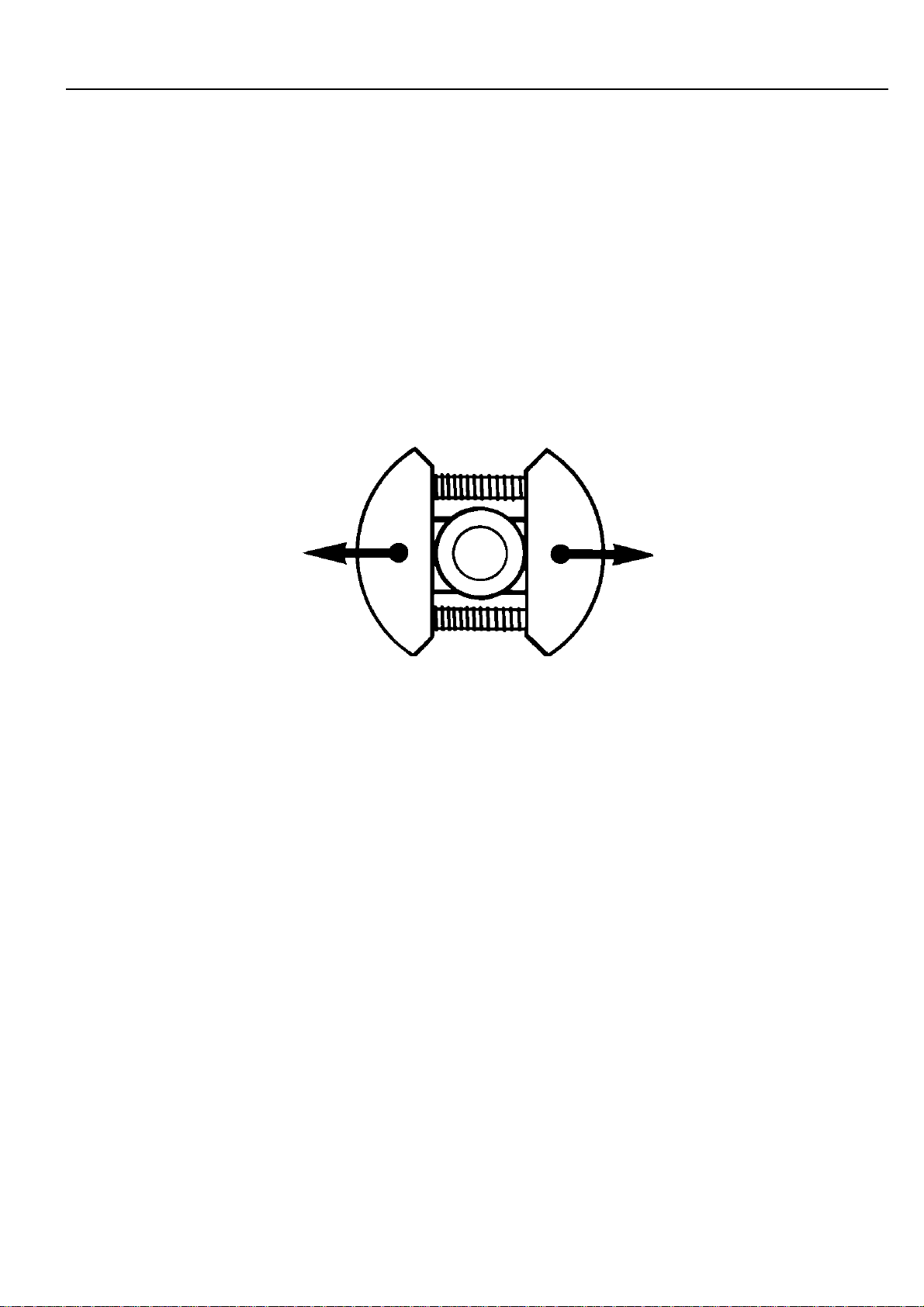
For Husqvarna Parts Call 606-678-9623 or 606-561-4983
Centrifugal clutch
4.
Contents
Clutch and clutch drum
Model 265 ________________________________ 82
Model 250 ________________________________ 85
Model 250PS _____________________________ 89
Models 240/245 ___________________________ 90
Models 225R/232R_________________________ 92
Models 225L/232L _________________________ 92
Models 225/232/235 ________________________ 92
Models 225 H60/H75 _______________________ 93
Models 225 AI15, 225 AI25 __________________ 94
Model 235 ________________________________ 95
Model 240RBD ____________________________ 97
Models 322, 325 ___________________________ 98
Model 122 _______________________________ 100
Models 32, Mondo ________________________ 102
Model 18H ______________________________ 104
Technical data ____________________________ 106
www.mymowerparts.com
81
Page 83
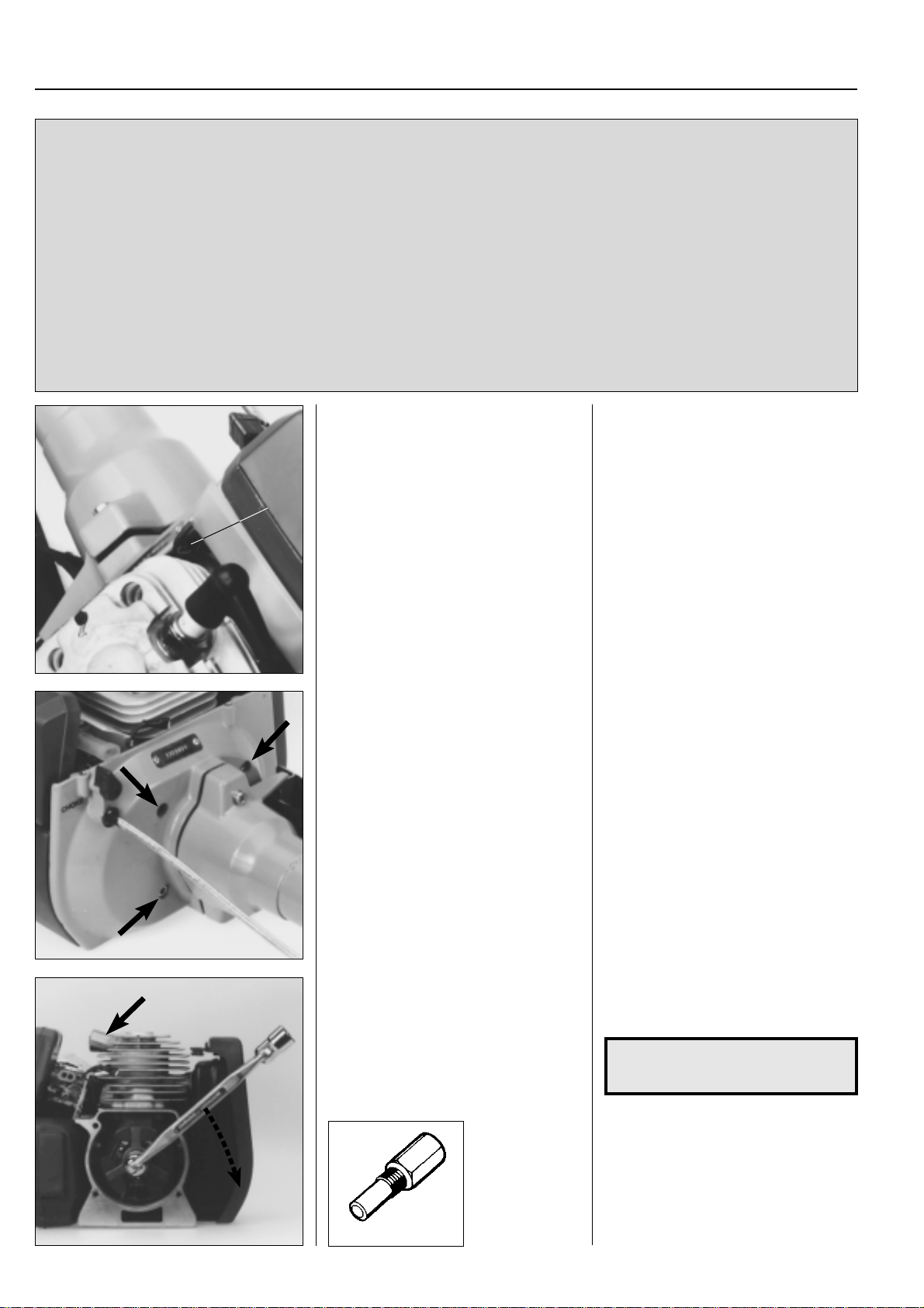
For Husqvarna Parts Call 606-678-9623 or 606-561-4983
4
The centrifugal clutch has the task of transferring
the power from the engine to the cutting equipment.
As the name implies, it works according to a centrifugal principle.
This means the clutch's friction shoes are thrown
outwards towards the clutch drum at a certain
engine speed. When the friction against the drum is
sufficiently great it drives the drive shaft at the
same speed as the engine.
Centrifugal clutch
Clutch model 265
Dismantling
Remove the cylinder cover and the earth
cable (A).
A
Some slipping occurs between the clutch and
the clutch drum when accelerating as well as in
the reversed situation when the cutting equipment jams. Thereby preventing abnormal load
changes on the crankshaft.
The engagement speed has been carefully tested
so that the engine can idle without the cutting
equipment's drive shaft rotating.
Clutch model 265
Dismantling
Remove the cylinder cover and the earth
cable (A).
Undo the screws and lift off the clutch
cover complete with the shaft.
Dismantle the centrifugal clutch from the
crankshaft.
Undo the 4 bolts that hold the clutch cover
on the engine body.
Lift off the complete unit with shaft and
clutch cover.
Replace the spark plug with the piston
stop no. 504 91 06-05. Unscrew the clutch
from the crankshaft.
NOTE!
Left-hand thread!
82
502 54 15-01
www.mymowerparts.com
Page 84
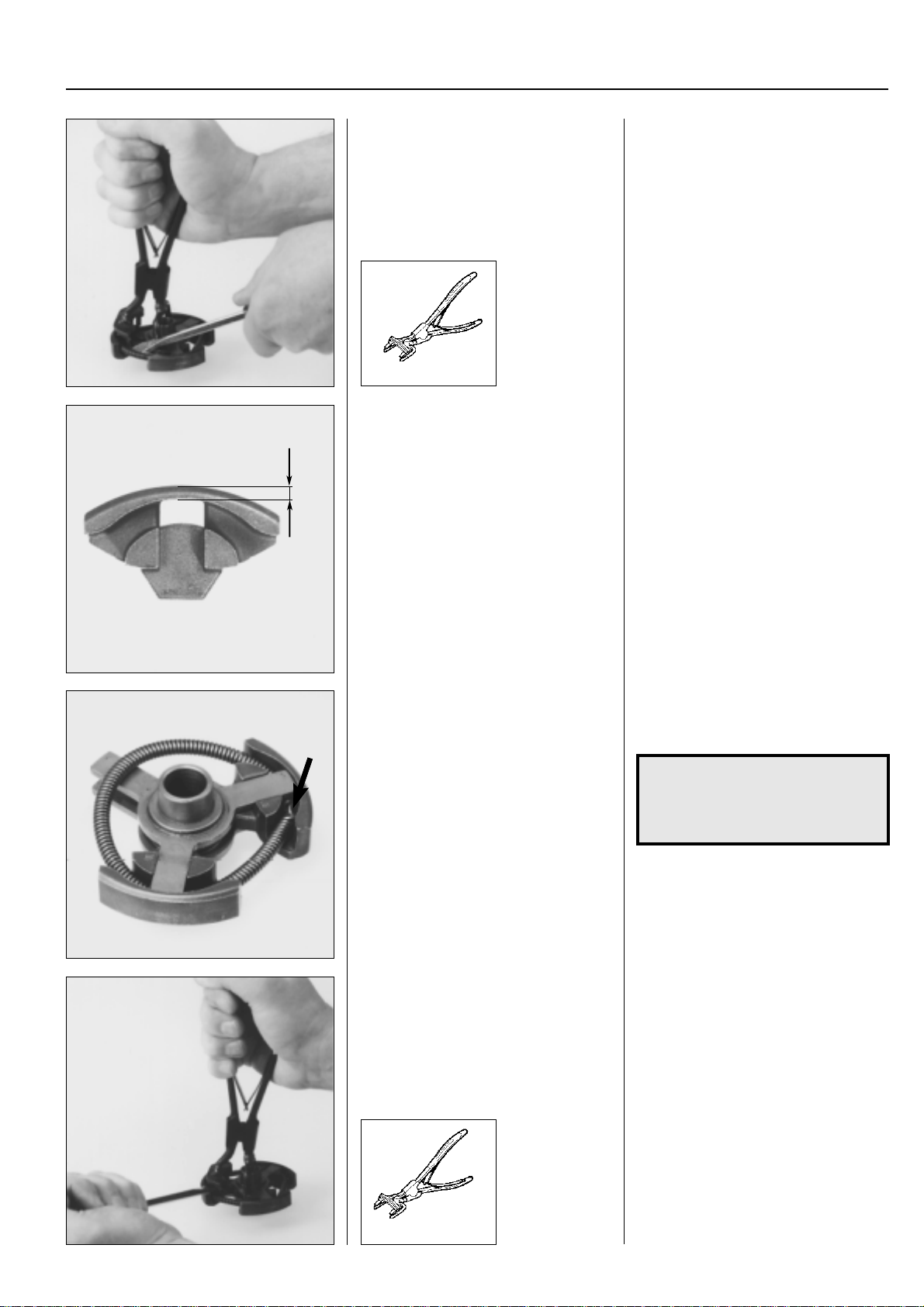
For Husqvarna Parts Call 606-678-9623 or 606-561-4983
Centrifugal clutch
Remove the clutch springs.
502 50 49-01
Clean and inspect the clutch parts with
regard to damage and wear.
min. 1 mm
4
Remove the clutch springs using pliers
no. 502 50 49-01 and a screwdriver.
Clean and inspect the clutch hub's arms
and the clutch shoes with regard to wear.
There must be at least 1 mm of material
remaining on the most worn area on the
clutch shoes.
All shoes must be replaced at the same
time.
Assembly
Place two clutch shoes and the spring on
the clutch hub.
Fit the remaining clutch shoe. Fit the remaining clutch shoe. Use the
Assembly
Place two clutch shoes and the spring on
the clutch hub.
NOTE!
The spring's connection point
should come in the centre of one
of the hub's arms.
assembly pliers no. 502 50 49-01 and a
screwdriver.
502 50 49-01
www.mymowerparts.com
83
Page 85
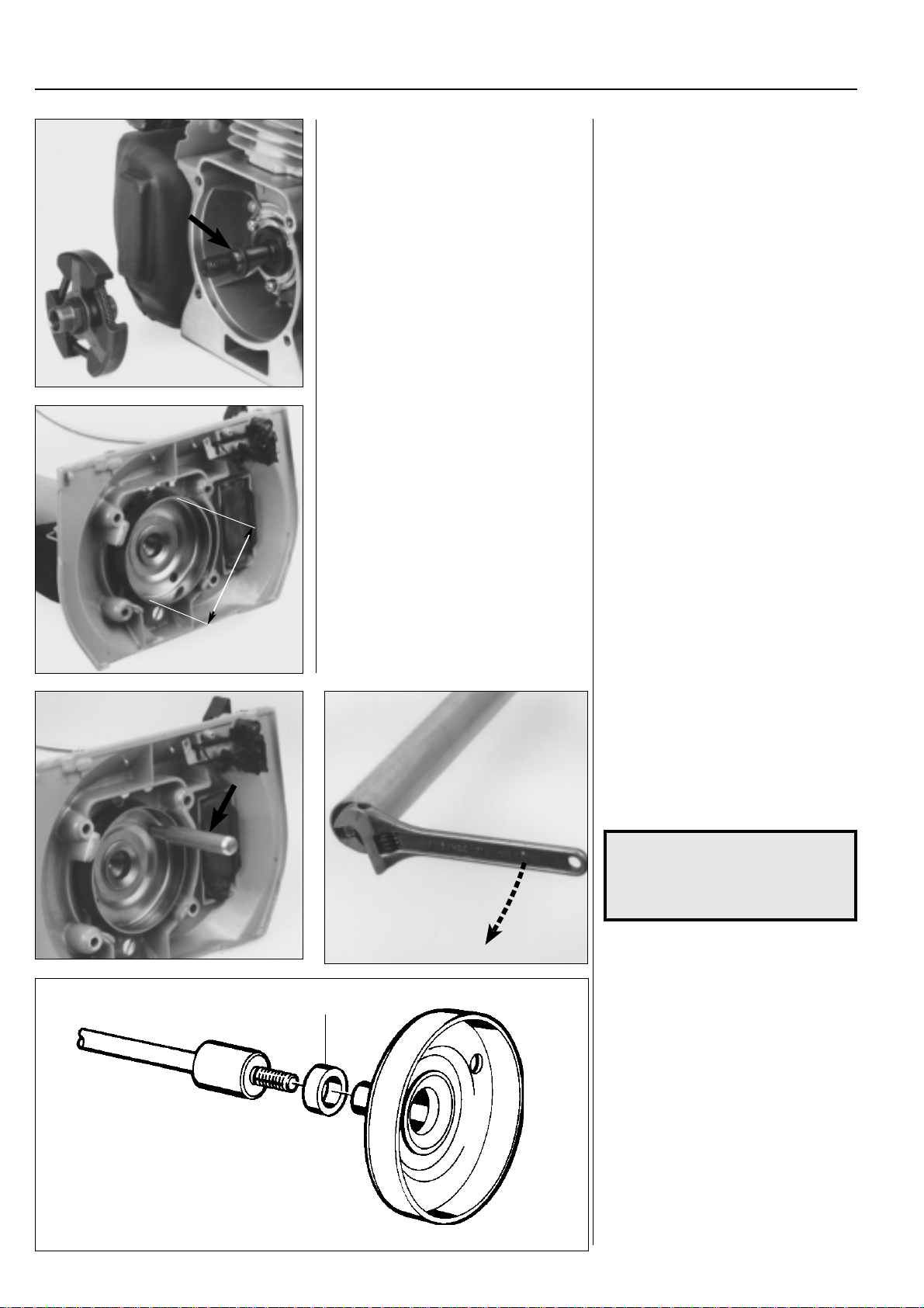
For Husqvarna Parts Call 606-678-9623 or 606-561-4983
4
Centrifugal clutch
Fit the clutch on the crankshaft.
Clutch drum
Model 265
Check the clutch drum for damage and
wear.
Replace the clutch drum if necessary.
Fit the clutch on the crankshaft.
Do not forget the thick spacer inside the
clutch.
Tighten the clutch.
Clutch drum
Model 265
Check the clutch drum for damage and
wear.
Measure the inside diameter of the drum.
It must not be greater than 80.0 mm.
Replace with a new drum if this is the
case.
Max. 80.0
Dismantle the angle gear so that the end
of the drive shaft is accessible.
Lock the clutch drum by inserting a suitable punch through one of the holes so
that it rests against one of the reinforcement ribs in the clutch cover. (See photo).
Undo the drive axle.
NOTE!
Left-hand thread.
Clutch drum can be extremely
tight.
It is far easier when fitting the clutch drum
A
to keep the shaft vertical with the clutch
drum facong upwards. This is so the
spacer (A) can be centred around the
drive shaft when the clutch drum is
screwed in position.
Fit all other parts in the reverse order set
out for dismantling.
84
www.mymowerparts.com
Page 86
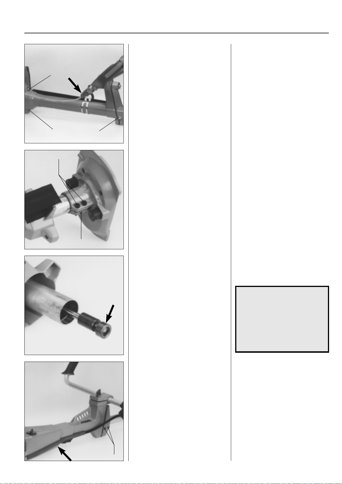
For Husqvarna Parts Call 606-678-9623 or 606-561-4983
Centrifugal clutch
Drive shaft
Model 265
Replace the drive shaft if the splines are
A
A
C
B
worn.
Loosen the throttle and remove the screws
(A).
Loosen the screw (B).
Pull off the clutch cover from the tube and
pull out the drive shaft.
Drive shaft
Model 265
Check the drive shaft. If the splines where
the shaft meshes with the angle gear are
worn it should be replaced.
Loosen the throttle from the handle and
remove the screws (A).
Loosen the screw (B).
Separate the clutch cover and the outer
support so the screws (C) and the stop
screw (D) are accessible.
Loosen the screws and pull off the clutch
cover from the tube.
Pull out the drive shaft and check it. If it is
bent it must be replaced under all circumstances.
4
D
Replace the vibration dampers if necessary.
Assemble the drive shaft and the remaining parts in the reverse order set out for
dismantling.
Clutch
Model 250
Dismantle the cover strip and loosen the
screws (A).
It is now appropriate to replace the vibration dampers if damaged.
Assembly takes place in the reverse order
set out for dismantling.
NOTE!
Lubricate the drive shaft using
engine oil before assembling and
do not forget the spacer before
the shaft is slid into the clutch
cover.
The tube should be slid into the
clutch cover as far as possible so
that it rests against the bearing.
Clutch
Model 250
Dismantle the following:
Cylinder cover, fuel pipe on the carburet-
tor and the cover strip over the throttle
cable and short-circuit cable.
Loosen the screws (A).
A
www.mymowerparts.com
85
Page 87
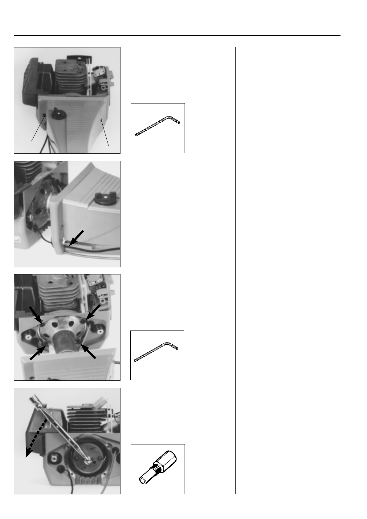
For Husqvarna Parts Call 606-678-9623 or 606-561-4983
4
Centrifugal clutch
Remove the screws (B) and (C).
B
C
502 21 58-01
Slide the tank unit forwards on the shaft.
Remove the screws (B) and (C). Use tool
no. 502 21 58-01 to access the screws
(C).
Remove the throttle from the handles.
Thread the throttle cable and the short
circuit cable through the slot in the fuel
tank.
Slide the tank unit forwards on the shaft.
Remove the screws holding the clutch
housing and separate the shaft from the
engine.
502 21 58-01
Dismantle the clutch nut. Replace the spark plug with piston stop
Remove the screws holding the clutch
housing on the engine body and pull away
the entire shaft unit.
no. 504 91 06-05.
Remove the nut holding the clutch.
86
504 91 06-05
www.mymowerparts.com
Page 88
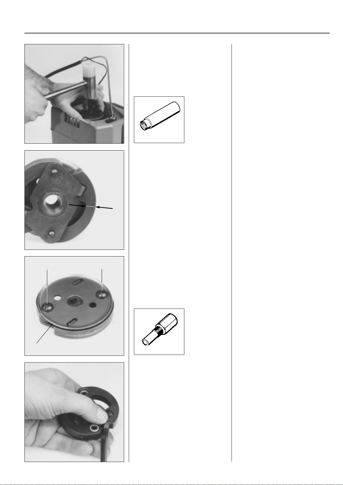
For Husqvarna Parts Call 606-678-9623 or 606-561-4983
Centrifugal clutch
Dismantle the clutch from the crankshaft.
505 26 79-12
Check the clutch shoes for wear. Replace
if necessary.
4
Fit the drift no 505 26 79-12 on the crankshaft. Do not screw it down fully against
the clutch.
Lift the engine body by the clutch and
apply a few sharp blows with a hammer to
the drift until the clutch becomes loose.
Check the clutch shoes for wear by measuring the distance (A). It must not be
below 3 mm. If this is the case replace
both shoes.
A
Remove the screws (B) and cover wash-
B
C
B
ers (C).
504 91 06-05
Remove the clutch shoes from the hub. Pry off the clutch shoes from the hub
Strip the clutch by first removing the
screws (B) and then lift off the cover
washers (C).
using a screwdriver. Keep your thumb
over the spring as shown in the photo.
www.mymowerparts.com
87
Page 89
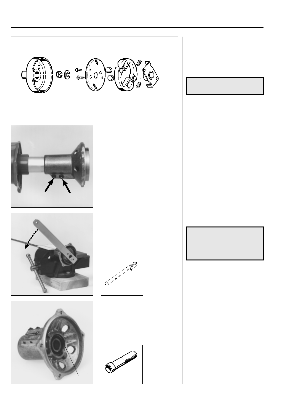
For Husqvarna Parts Call 606-678-9623 or 606-561-4983
4
Centrifugal clutch
Clutch drum
Model 250
Dismantle the clutch housing complete.
Check all the parts with regard to wear
and damage. Replace faulty parts.
Assemble in the reverse order set out for
dismantling.
Compress the spring using a pair of flat
nose pliers and insert it in the cut-out in
the clutch shoes.
NOTE!
Use Loctite on the screws.
Clutch drum
Model 250
Loosen the screws holding the clutch
housing on the shaft.
Pull off the clutch housing complete with
the clutch drum and the drive shaft from
the tube.
Undo the clutch drum from the drive shaft. Clamp the drive shaft in a vice and undo
the clutch drum.
NOTE!
Use vice guards on the vice so not to
damage the drive shaft.
Use tool no. 502 52 16-01 to undo the
clutch drum.
Check the clutch drum for wear. The inside diameter must not exceed 70.0 mm.
502 52 16-01
Remove the circlip and bearing from the
clutch housing.
Remove the circlip (A).
Carefully heat the clutch housing (approx.
150°C) and press out the bearing using
the punch no. 505 38 17-09.
88
A
505 38 17-09
www.mymowerparts.com
Page 90
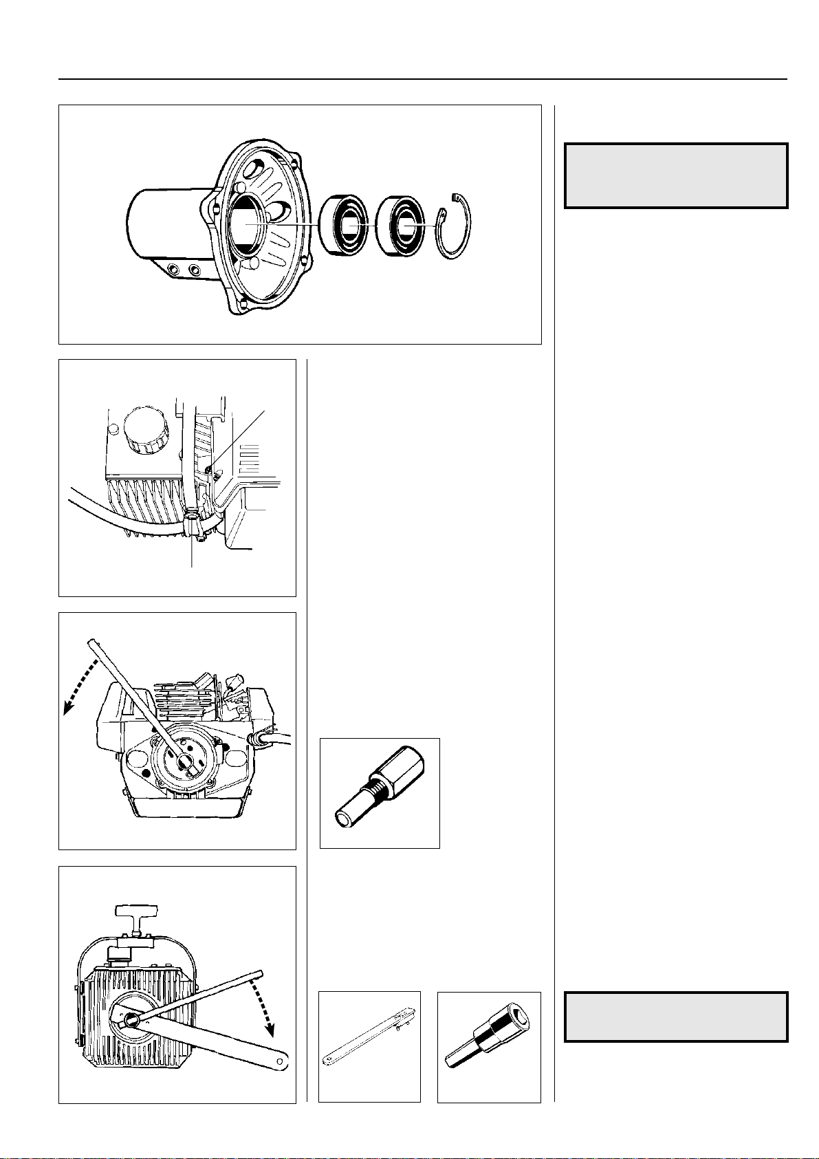
For Husqvarna Parts Call 606-678-9623 or 606-561-4983
Centrifugal clutch
Clutch
Model 250PS
B
Unscrew the cable clamp (A) and the
hose clamp (B).
Turn the hydraulic oil tank clockwise and
pull it off from the engine body.
4
Replace faulty parts and assemble in the
reverse order set out for dismantling.
NOTE!
Use Loctite on the clutch drum's
threads.
The bearing is easier to fit if the clutch
housing is hot (approx. 150°C).
Clutch
Model 250PS
The clutch on this model is positioned
between the engine body and the hydraulic unit.
1. Unscrew the clamp (A) holding the
control cable on the hydraulic oil tank.
2. Loosen the hose clamp (B).
3. Turn the hydraulic oil tank clockwise
and pull it off from the engine body.
(Bayonet fitting).
A
Remove the clutch nut and dismantle the
clutch according to the instructions for
model 250.
504 91 06-05
Clutch drum
Model 250PS
Dismantle the clutch drum from the hydraulic unit’s axle.
Dismantle the cylinder cover and replace
the spark plug with piston stop no. 504 91
06-05.
Remove the clutch nut by turning it anticlockwise.
Dismantle the clutch from the crankshaft
and carry out an inspection and servicing
as set out in the instructions for model
250.
Clutch drum
Model 250PS
The clutch drum is screwed onto the
hydraulic unit’s axle.
Dismantle the drum by using the holding
tool 502 52 16-01 and allen key
502 52 14-01.
502 52 16-01
502 52 14-01
www.mymowerparts.com
NOTE!
Turn the allen key clockwise.
Replace the clutch drum if the inner diameter exceeds 70.0 mm.
89
Page 91
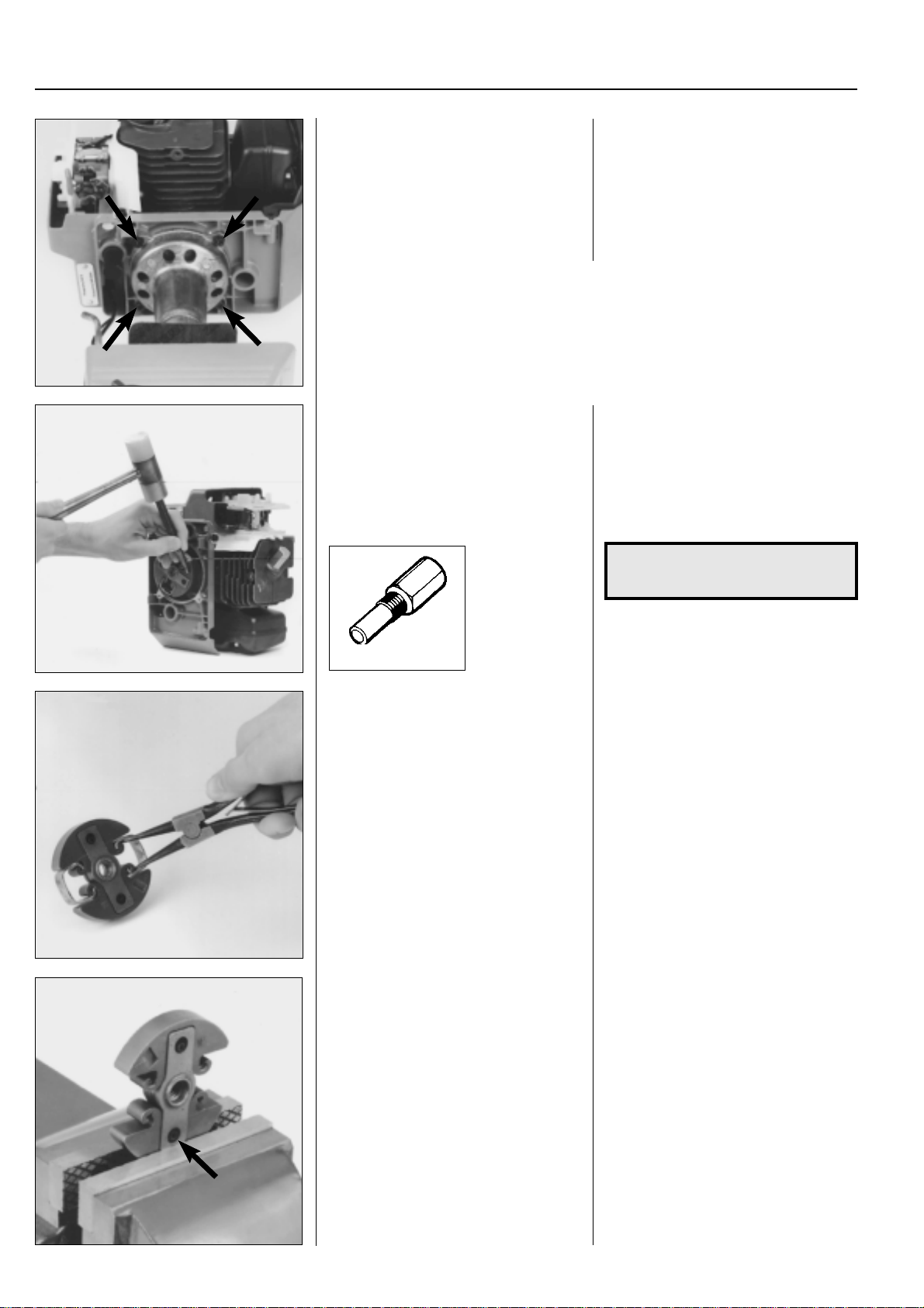
For Husqvarna Parts Call 606-678-9623 or 606-561-4983
4
Centrifugal clutch
Clutch
Models 240/245
Separate the engine body and tank unit.
Remove the screws by the clutch housing
and remove the shaft.
The clutch can be one of two different designs. Firstly , a three shoe clutch of the same
type as used on model 235. See this model for service measures. This clutch was
introduced from the following serial numbers:
Model 240R no. 82 00 059, model 245R no. 81 70 180, model 245RX no. 81 60 227.
Secondly, the clutch can be a two shoe model as described below.
Dismantle the clutch using a punch and
hammer.
Clutch
Models 240/245
Separate the engine body and the tank
unit in the same way as described for
model 250.
Remove the screws that hold the clutch
housing against the engine body and lift
off the entire shaft unit.
Replace the spark plug with piston stop
no 504 91 06-05. Loosen the clutch shoes
from the crankshaft.
One of the clutch shoes is countersunk to
give a purchase for a punch.
Loosen the clutch with a few heavy blows
from a hammer.
NOTE!
The clutch has a left-hand thread.
504 91 06-05
Remove the leaf springs.
Press out the tubular pins. Use a suitable punch to remove the tubu-
Remove the leaf springs by pressing apart
the ends using a pair of circlip pliers.
lar pins so that the clutch shoes can be
replaced.
90
www.mymowerparts.com
Page 92
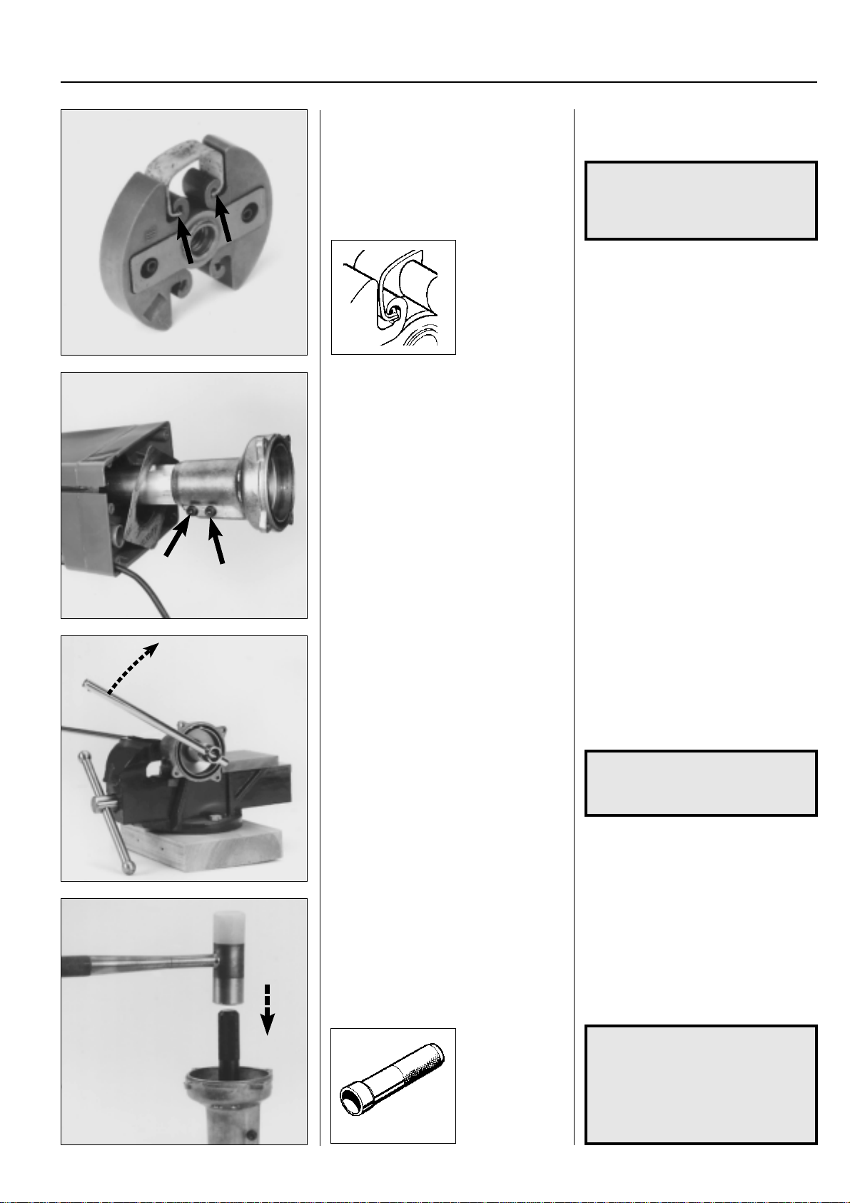
For Husqvarna Parts Call 606-678-9623 or 606-561-4983
Centrifugal clutch
Replace any worn or damaged parts and
ensure the clutch springs are fitted correctly.
Pull off the clutch housing complete from
the tube.
4
Replace any worn or damaged parts.
Both clutch shoes should be replaced at
the same time.
NOTE!
Check when fitting the clutch
springs that the small pins are on
each side of the clutch shoes.
Loosen the screws that hold the clutch
housing on the tube.
Pull off the clutch housing complete with
clutch drum and drive shaft from the tube.
Clutch drum
Models 240/245
Undo the clutch drum.
Heat the clutch housing and press out the
bearing.
505 38 17-09
Clutch drum
Models 240/245
Clamp the drive shaft in a vice and undo
the clutch drum. 19 mm spanner.
Use vice guards so that the drive shaft is
not damaged.
NOTE!
The clutch drum has a left-hand
thread.
Carefully heat the clutch housing to about
150°C and press out the bearing using a
suitable punch, e.g. 505 38 17-09.
Replace any damaged parts and assemble
in the reverse order set out for dismantling.
The bearing is easier to fit if the clutch
housing is hot (approx. 150°C).
NOTE!
Use Loctite on the clutch drum's
threads.
Do not forget the heat shield
between the clutch housing and
the fuel tank.
www.mymowerparts.com
91
Page 93
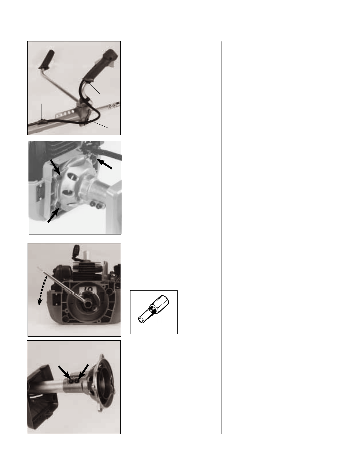
For Husqvarna Parts Call 606-678-9623 or 606-561-4983
4
Centrifugal clutch
Clutch
Models 225 R/232 R
Dismantle the throttle and cable channel.
Models 225 L/232 L
Remove the cylinder cover.
Loosen the throttle cable from the carbu-
B
A
C
rettor and lift off the cable guide from the
crankcase.
Separate the shaft unit from the engine
body.
Clutch
Models 225 R/232 R
Dismantle the screw (A) that holds the
throttle and screw (B) on the cable channel.
Loosen the screw (C) and slide the handle clamp forwards on the shaft.
Dismantle the cylinder cover.
Models 225 L/232 L
Remove the cylinder cover.
Loosen the throttle on the carburettor and
lift off the cable guide from the crankcase.
Remove the 4 screws that hold the clutch
cover on the crankcase.
Now remove the entire shaft unit from the
engine body .
Dismantle the clutch from the crankshaft.
504 91 06-05
Clutch drum
Models 225/232/235
Dismantle and assemble the clutch housing, clutch drum and its bearings in the
same way as described for model 250.
Replace the spark plug with piston stop
no. 504 91 06-05 and dismantle the clutch
from the crankshaft.
Clutch drum
Models 225/232/235
Loosen the two screws holding the clutch
housing on the shaft.
Pull off the clutch housing complete with
clutch drum and drive axle in the shaft.
Dismantle and assemble the clutch drum
and its bearings in the same way as
described for model 250.
92
www.mymowerparts.com
Page 94
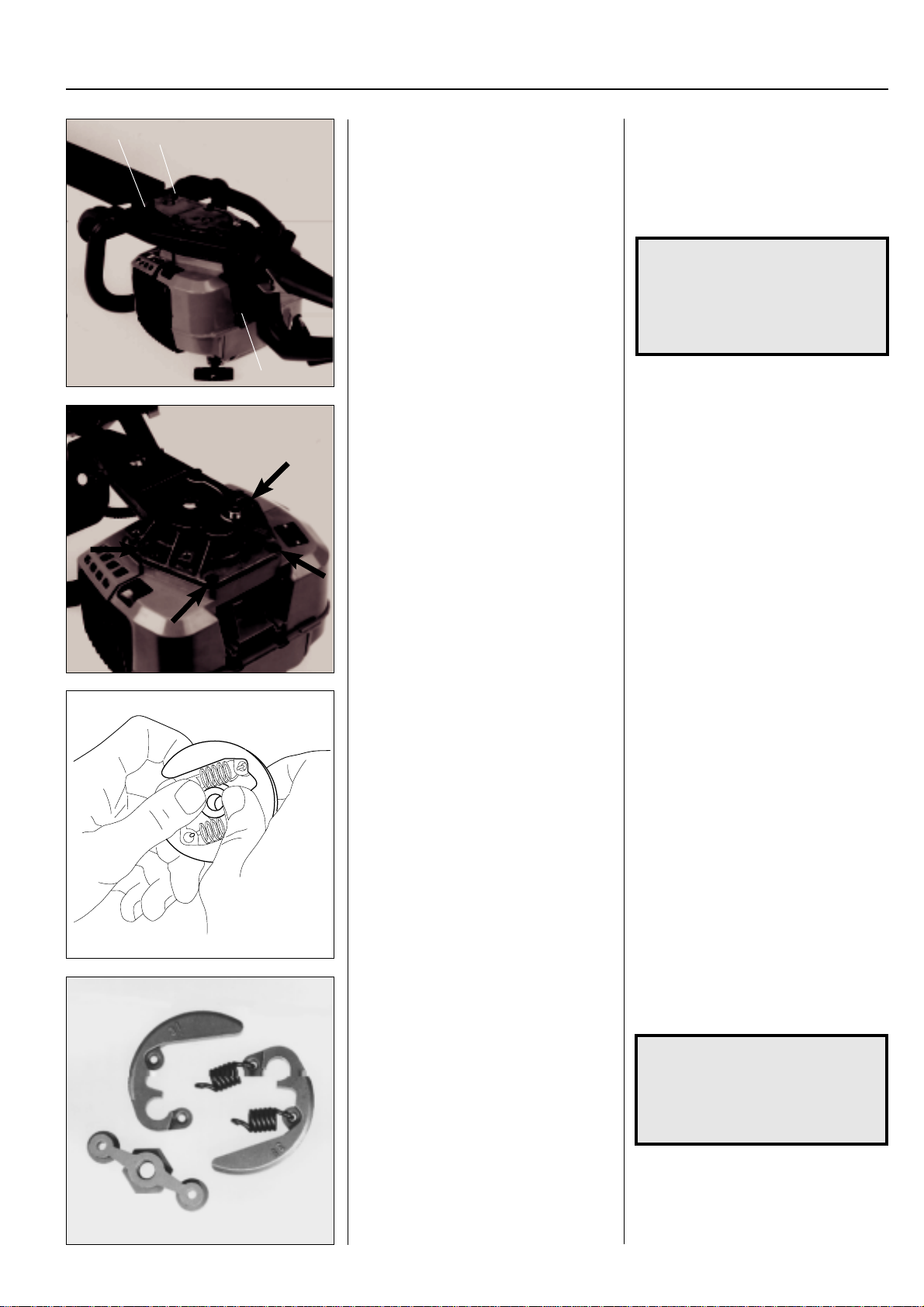
For Husqvarna Parts Call 606-678-9623 or 606-561-4983
Centrifugal clutch
A
A
B
Models 225 H60/H75
Separate the engine body and cutting
equipment.
Dismantle the cutting equipment and
clutch from the engine.
Models 225 H60/H75
Separate the engine body and cutting
equipment as follows:
Remove the 4 screws (A) and (B) by the
vibration dampers to remove the handle
assembly.
WARNING!
!
Remove the screws that hold the clutch
cover on the crankcase.
Lift off the clutch cover complete with the
cutting equipment.
Dismantle the clutch from the crankshaft
in the same way as described above.
The transport guard
should always be fitted
when working on the
cutting equipment to avoid
cuts to the hands.
4
Press out the clutch hub. Strip this type of clutch by pressing out
the clutch hub from the back using your
thumbs.
Inspect the parts of the clutch with regard
to wear and damage.
Inspect the clutch shoes with regard to
wear on the bearing points and the springs
for crack formation or breakage.
NOTE!
The shoes and springs should
always be replaced in pairs.
Also check the clutch centre's
shoe bearings.
www.mymowerparts.com
93
Page 95
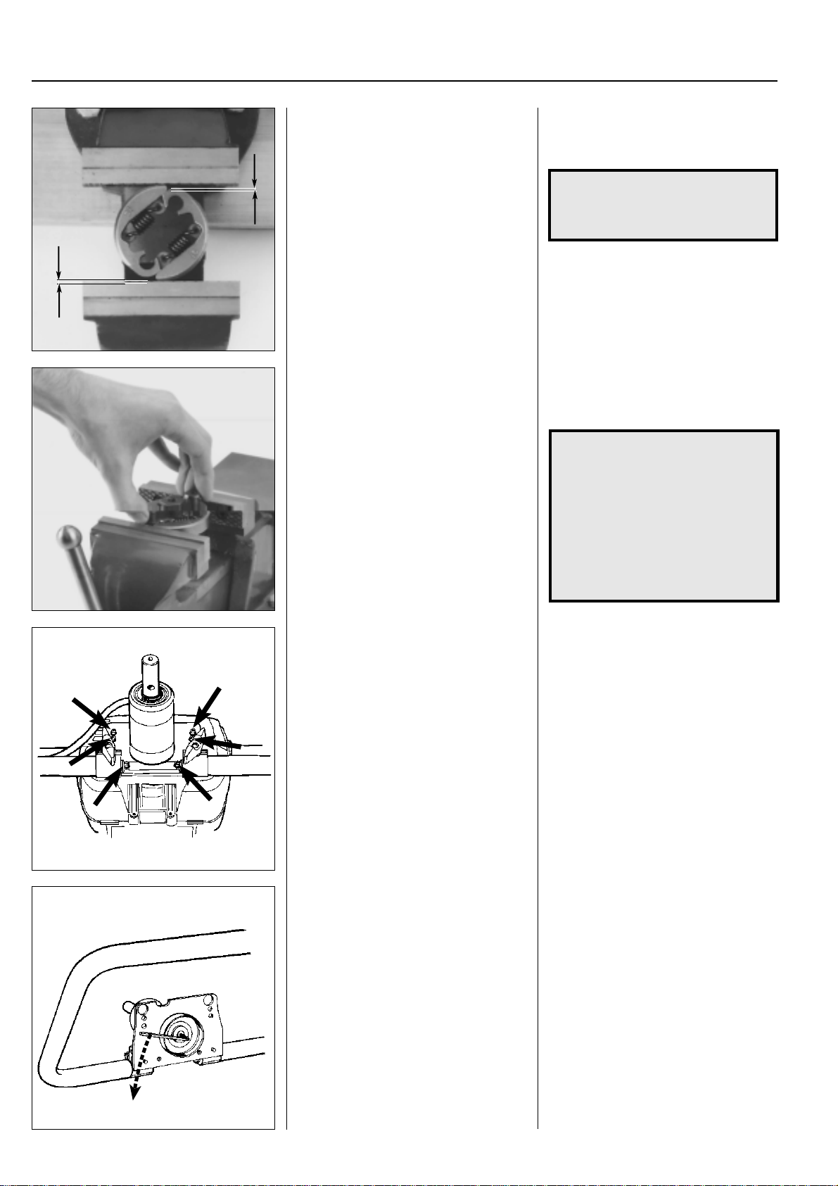
For Husqvarna Parts Call 606-678-9623 or 606-561-4983
4
Centrifugal clutch
Hook on the springs and place the clutch
in a vice.
Tighten the vice carefully and position the
centre.
Start to assemble the clutch by hooking
the springs in the clutch shoes.
Then place the clutch in a vice as shown.
NOTE!
The bevel on the clutch shoes
should face upwards.
Tighten the vice sufficiently so that the
clutch centre can be positioned.
Fit the clutch on the crankshaft.
NOTE!
Do not forget the large flat washer
between the clutch and the
crankcase.
The washer acts as a support for
the clutch shoes. If the washer is
missing the shoes can be forced
out of the hub when the engine is
run causing damage to the
crankcase.
Clutch drum
Models 225 H60/H75
See chapter "Attachments".
Clutch
Models 225 AI15, 225 AI25
Dismantle the gearbox from the engine
body to access the clutch and clutch
drum.
Also see the previous section for model
225/232 concerning servicing the clutch.
Clutch drum
Models 225 AI15, 225 AI25
Dismantle the screw and lift out the clutch
drum.
Clutch drum
Models 225 H60/H75
See chapter "Attachments".
Clutch
Models 225 AI15, 225 AI25
Remove the 6 screws holding the gear
housing on the engine body and lift off the
gearbox.
See the previous section for model 225/
232 with regard to service and assembly
of the clutch.
Clutch drum
Models 225 AI15, 225 AI25
The clutch drum can be removed once
the screw in the centre is unscrewed
anticlockwise.
Replace the clutch drum if the inner diameter exceeds 64.5 mm.
94
www.mymowerparts.com
Page 96
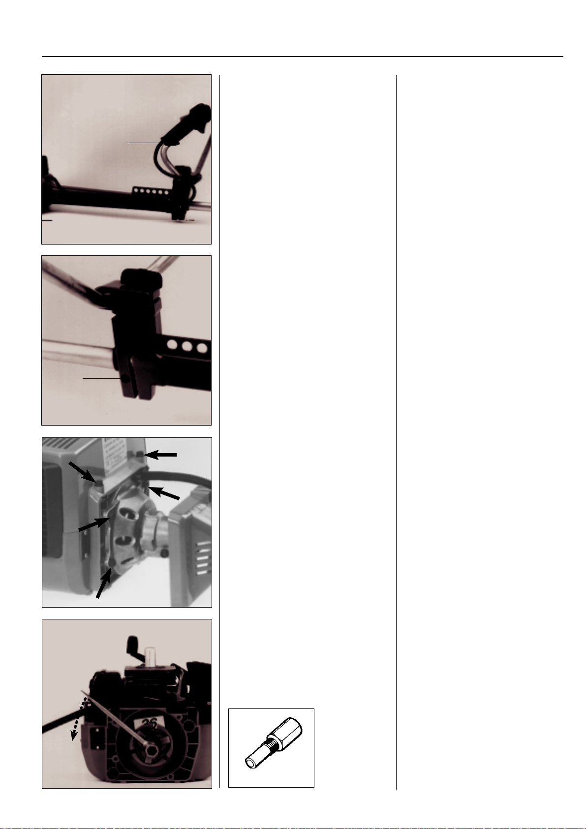
For Husqvarna Parts Call 606-678-9623 or 606-561-4983
Centrifugal clutch
Clutch
Model 235
Dismantle the throttle. Snap off the protective casing.
A
Loosen screw (B).
Slide the plastic cover complete with
handle forwards on the shaft.
Clutch
Model 235
Dismantle the throttle by removing screw
(A).
Snap off the protective casing for the
throttle cable and the short circuit cable.
Loosen screw (B) and slide the plastic
cover complete with handle forwards on
the shaft so that the screws holding the
clutch housing become accessible.
4
B
Dismantle the clutch cover and the cylinder cover.
Dismantle the clutch from the crankshaft. Replace the spark plug with piston stop
Remove the four screws holding the clutch
cover on the crankcase.
Remove the cylinder cover.
no.504 91 06-05 and dismantle the clutch
from the crankshaft.
504 91 06-05
www.mymowerparts.com
95
Page 97
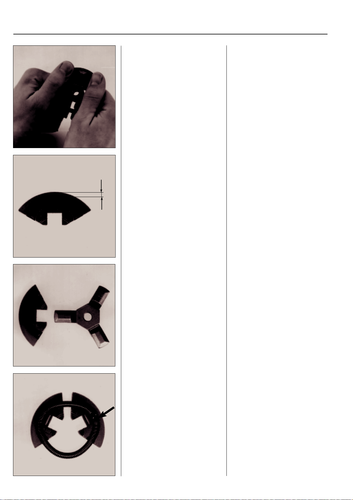
For Husqvarna Parts Call 606-678-9623 or 606-561-4983
4
Centrifugal clutch
Strip the clutch. Strip the clutch by pressing the clutch
shoes from behind using your thumbs.
The clutch shoes must have at least 1 mm
of material remaining.
Check that the shoes have at least 1 mm
of material remaining where they are
worn the most.
When replacing all three shoes should be
replaced at the same time to avoid imbalance.
min. 1 mm
Check the arms on the clutch centre and
the guide slots for wear.
The spring's connection point should be
positioned in the centre of the slot for the
clutch centre's arm.
Check that the arms on the clutch centre
are not heavily worn or show signs of
cracking and that the clutch shoe guide
slots are not elongated. When replacing
all shoes the clutch centre should be
replaced at the same time.
When assembling the clutch the spring is
first positioned in one clutch shoe so that
the spring's connection point comes in
the centre of the slot for the clutch centre's
arm.
Then place the spring in one more shoe.
96
www.mymowerparts.com
Page 98
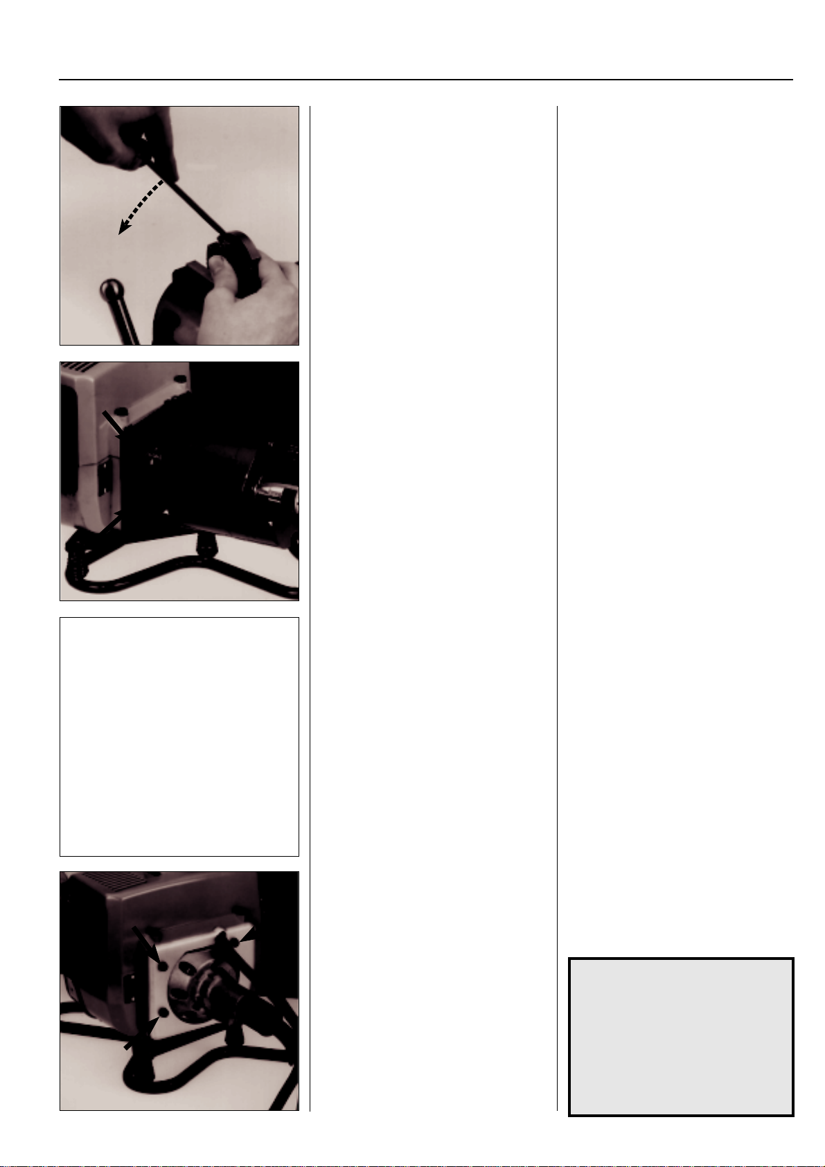
For Husqvarna Parts Call 606-678-9623 or 606-561-4983
Centrifugal clutch
Position the clutch hub.
Clamp the clutch in a vice and bend out
the spring using a screwdriver so that the
third clutch shoe can be fitted.
On model 235 P the clutch is accessible
when the hydraulic unit has been dismantled.
Dismantle the clutch from the crankshaft.
4
Now position the clutch hub and then
clamp the clutch in a vice.
Use a screwdriver to bend out the spring
so that the third clutch shoe can be
pressed into place.
Use a pair of flat nose pliers to locate the
spring if necessary.
On model 235 P the clutch is accessible
when the hydraulic unit has been dismantled.
Remove the 4 screws and lift off the
hydraulic unit.
Dismantle the clutch from the crankshaft
in the same way as set out for models
225/232.
The clutch has the same design as models
225/232.
Clutch drum
Models 235, 235P
See chapter "Hydraulic unit".
Clutch
Models 240 RBD
Dismantle the cover plate and the clutch
housing.
Unscrew the clutch from the crankshaft.
Clutch drum
Models 235, 235P
See chapter "Hydraulic unit".
Clutch
Models 240 RBD
Remove the 4 screws holding the cover
plate and clutch housing on the crankcase.
Dismantle the clutch from the crankshaft
as explained for models 225/232.
The clutch has the same design as models
225/232.
NOTE!
Do not forget the large flat washer
between the clutch and the
crankcase.
The washer acts as a support for
the shoes, and if missing the
shoes can be forced out of the
hub when the engine is run
causing damage to the crankcase.
www.mymowerparts.com
97
Page 99
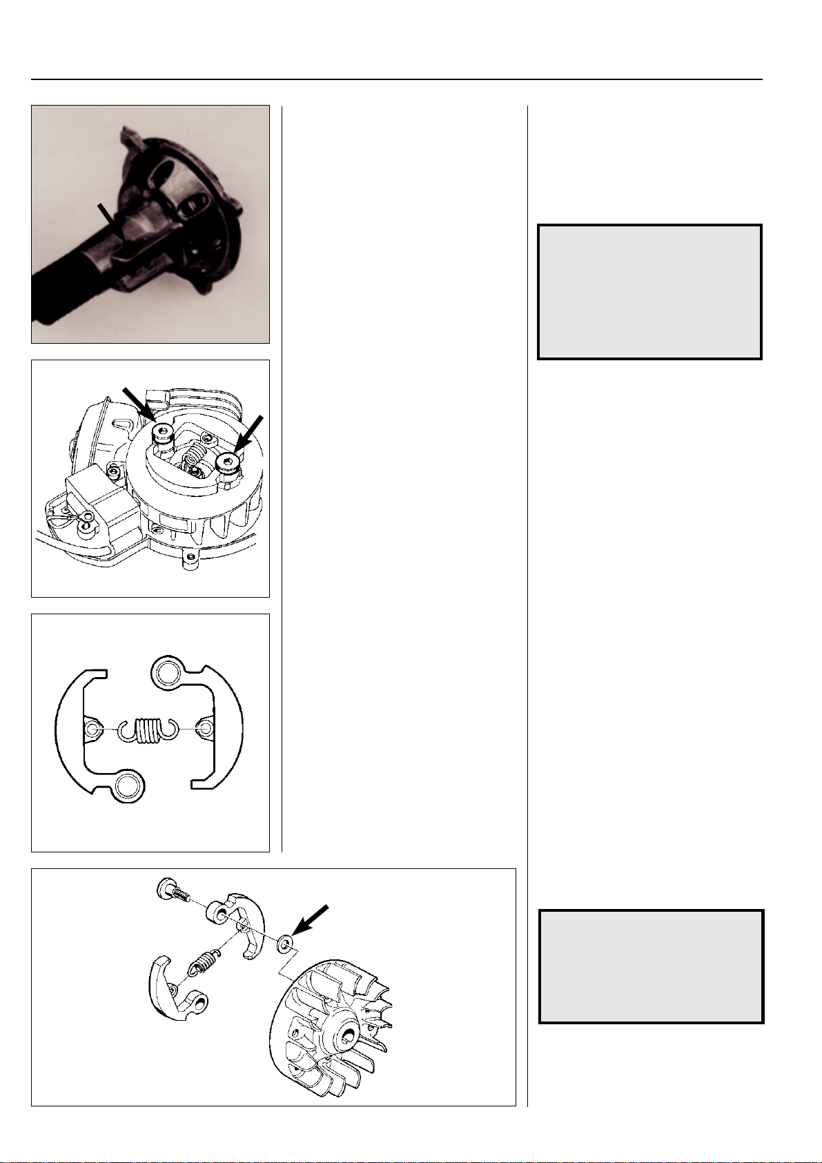
For Husqvarna Parts Call 606-678-9623 or 606-561-4983
4
Centrifugal clutch
Clutch drum
Model 240 RBD
Loosen the screws so that the drive shaft
can be pulled out of the clutch housing.
Clutch
Models 322, 325
Dismantle the clutch by following the instructions in the chapter "Ignition system".
Clutch drum
Model 240 RBD
Loosen the screws so that the drive shaft
can be pulled out of the clutch housing.
Dismantle and assemble the clutch housing and its parts in the same way as
described for model 250.
NOTE!
The screw that holds the drive
shaft in place should be screwed
in the clutch housing from the
threaded side (not through the
free hole) so that the drive shaft
can be turned freely in the clutch
housing.
Clutch
Models 322, 325
The centrifugal clutch is bolted to the
flywheel.
Follow the detailed instructions in the
chapter "Ignition system" when the clutch
is to be dismantled.
Twist apart the clutch and inspect the
different parts with regard to wear or
damage.
Twist apart the clutch.
Inspect the different parts with regard to
wear or damage.
Pay special attention to the ends of the
springs, which in addition to wear, can
also show signs of cracking.
Connect the clutch shoes together with
the spring.
NOTE!
Both clutch shoes should be
replaced even if only one of them
is showing signs of heavy wear.
This is to avoid engine vibration
caused by imbalance in the clutch.
98
Bolt the clutch on the flywheel. Do not
forget the washers between the flywheel
and the clutch shoes.
www.mymowerparts.com
Page 100
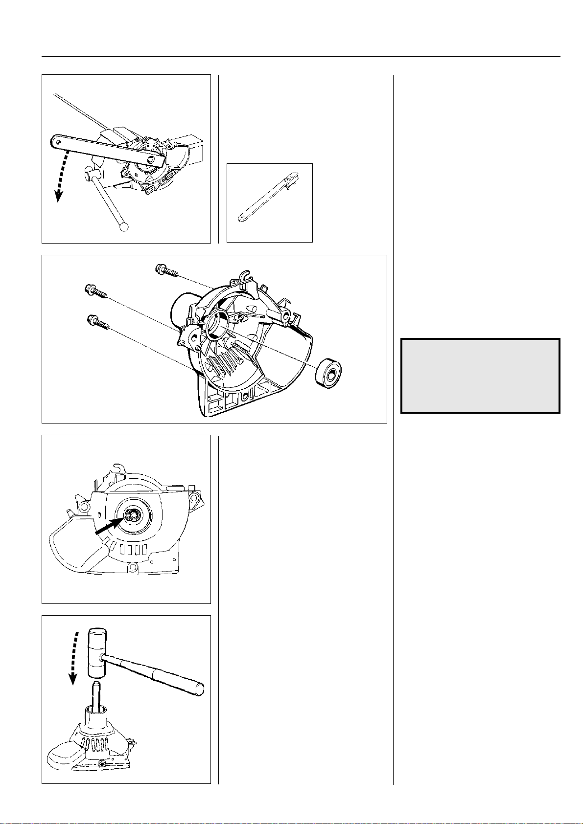
For Husqvarna Parts Call 606-678-9623 or 606-561-4983
Centrifugal clutch
Clutch drum
Models 322/325
Separate the shaft from the clutch cover.
Dismantle the clutch drum using tool 502
52 16-01.
502 52 16-01
4
Clutch drum
Models 322/325
Separate the shaft from the clutch cover.
Pull away the clutch cover complete with
drive axle and clutch drum.
The drum is bolted on the drive axle and
can be dismantled using tool 502 52 16-01.
The clutch drum should be replaced if the
diameter exceeds Ø 64.0 mm.
The bearing supporting the clutch drum
in the clutch cover is glued in position with
Loctite. To replace the bearing, heat the
cover to approx. 70°C using a hot air gun
and the glue will release.
Dismantle the bearing using an appropriate punch and hammer.
Model 322C
Dismantle the clutch cover and remove
the shaft’s mounting parts in the cover.
Remove the circlip.
Press off the clutch drum.
Replace the bearing and fit the remaining
parts in the reverse order as set out for
dismantling.
NOTE!
Dismantle the shaft’s mounting
clamps and rubber spacer in the
clutch cover so that these parts are
not damaged when the cover is
heated.
Assemble in the reverse order as set out
for dismantling.
Use Loctite intended for mounting bearings when the bearing is mounted in the
clutch cover.
Model 322C
Dismantle the clutch cover from the shaft.
Remove the shaft’s mounting parts on
the clutch cover.
Dismantle the circlip holding the clutch
drum’s spindle by the bearing.
Now press out the clutch drum using a
suitable punch and hammer.
The bearing is replaced in the same way
as described above.
Assemble in the reverse order as set out
for dismantling.
www.mymowerparts.com
99
 Loading...