


For Husqvarna Parts Call 606-678-9623 or 606-561-4983
Workshop Manual
385XP
www.mymowerparts.com

For Husqvarna Parts Call 606-678-9623 or 606-561-4983
CONTENTS
Introduction .................................................3
Safety regulations ....................................... 4
Symbols .......................................................5
Technical data .............................................6
Service tools................................................8
Troub le shooting .......................................10
Service information...................................12
Safety equipment ......................................14
Starter.........................................................19
Electrical system....................................... 21
Centrifugal clutch......................................26
Lubrication system ...................................28
Carburettor ................................................30
Tank unit.....................................................38
Anti-vibration system ...............................40
Cylinder and piston...................................41
Crankcase and crankshaft ....................... 45
www.mymowerparts.com

For Husqvarna Parts Call 606-678-9623 or 606-561-4983
INTRODUCTION
General
This Workshop Manual provides a comprehensive description
of how to trouble shoot, repair and test the chainsaw. A
description of different safety measures that should be taken
during repair work is also given.
Safety
Note! The section dealing with safety should
be read and understood by all who carry out
repair and service work on the chainsaw .
Warning symbols can be found in this Workshop Manual and
on the chainsaw. See page 3. A new warning symbol must be
applied as soon as possible if a warning symbol on the
chainsaw has been damaged or is missing to ensure the
greatest possible safety when using the chainsa w .
Target Group
When producing this W orkshop Manual the assumption has
been made that personnel who use it have general knowledge
in the repair and service of small engines.
Layout
This W orkshop Manual can be used in two diff erent wa ys:
• For the repair of a particular system on the chainsaw .
• Dismantling and Assembly of the entire chainsaw .
Repair of a particular system
When a particular system on the chainsaw is to be repaired,
proceed as follows:
1. Look up the page for the system in question.
2. Carry out the sections: Dismantling
Cleaning and inspection
Assembly
Dismantling and Assembly of the entire chainsaw
Proceed as follows when the entire chainsaw is to be
dismantled and assembled:
1. Look up page 19, which deals with the Starter and
carry out the instructions under the heading
Dismantling.
2. Leaf forward in the book and carry out Dismantling in the
order given in the sections.
The Workshop Manual must be read and understood by
personnel who are to carry out repair work and service on the
chainsaw . The Man ual is also suitable for use when training
new employ ees.
Modifications
Modifications will be successively introduced on the chainsaw
during production. When these modifications affect servicing
and/or spare parts, separate service information will be sent
out on each occasion. This means that in time this Workshop
manual will become out of date. In order to prev ent this, the
Manual should be read together with all service information
issued concerning the chainsaw in question.
Tools
Special tools must be used during specific steps. All service
tools are listed in the Workshop Manual. Usage is evident
from respective sections.
Always use Husqvarna original parts:
3. Go back the the Starter on page 1 and carry out the
instructions under Cleaning and inspection.
4. Leaf forward in the book and carry out Cleaning and
inspection in the order given in the sections.
5. Order or take out all requisite spare parts from the stores.
6. Look up page 47 which deals with the Crankcase and
carry out the instructions under Assembly .
7. Leaf forward in the book and carry out Assembly in the
order given in the sections.
To improve understanding some sections provide a
Description first of the actual unit.
Numbering
Position references to components inside the figures are
designated A, and B, etc.
The figures are number 1, 2 etc.
The position references figure numbers restart in each new
section.
• Spare parts
• Service tools
• Accessories
English – 3
www.mymowerparts.com

For Husqvarna Parts Call 606-678-9623 or 606-561-4983
SAFETY REGULATIONS
General instructions
The workshop where chainsaw repairs are to be done must
be equipped with safety equipment as set out in local
regulations.
No one may repair the chainsaw unless they ha ve read and
understood the contents of this Workshop Manual.
This W orkshop Manual contains the following warning texts
in relevant places. Warning texts are positioned before the
procedures they refer to .
WARNING!
The warning text warns of the risk of
personal injury if the instructions are
not followed.
NOTE!
This text warns of material damage if the
instructions are not followed.
Special instructions
The fuel used in the chainsaw has the following hazardous
properties:
1. The fluid and its fumes are poisonous.
2. Can cause skin irritation.
3. Is highly inflammable.
The bar, chain and clutch cov er (chain brake) must be fitted
before the saw is started otherwise the clutch can work loose
and cause personal injury .
Wear ear-muffs when test running.
Do not use the saw until it has been adjusted so that the chain
remains still when idling.
After test running, do not touch the muffler until it has cooled.
Risk of burn injuries.
Insufficient lubrication of the chain can result in the chain
breaking, which can cause serious or even lif e-threatening
injury.
Ensure that the spring in the starter does not fly out and cause
personal injury .
If the spring tension is activated on the starter pulley when it
is to be taken up, the spring can fly out and cause personal
injury.
Check that the brake is applied when removing the pressure
spring on the chain brake. Otherwise the pressure spring can
fly out and cause personal injury .
After repair, the chain brak e must be checked in accordance
with the instructions on page 16.
When replacing the crankshaft bearings note that the
crankcase halves are hot. W ear protectiv e glov es
Do not direct the compressed air jet towards the body when
using compressed air. Air can penetrate into the blood
circulation, which means mortal danger.
4 – English
www.mymowerparts.com

STOP
For Husqvarna Parts Call 606-678-9623 or 606-561-4983
SYMBOLS
Symbols on the chainsaw Symbols in this Workshop Manual
The following symbols are moulded into the chainsaw casing.
This symbol indicates a risk of personal
injury if instructions are not followed.
Choke
Switch for hand grip heater
Fuel filler
Stop button
Screw to adjust chain lubrication
Chain oil filler
Electric carburettor heating
English – 5
www.mymowerparts.com
For Husqvarna Parts Call 606-678-9623 or 606-561-4983
TECHNICAL D ATA
Displacement Bore Stroke Max. po wer/rpm
3
cm
/ cubic inch Ømm/Øinch mm/inch kW/hp/ rpm
385XP 84.7cm
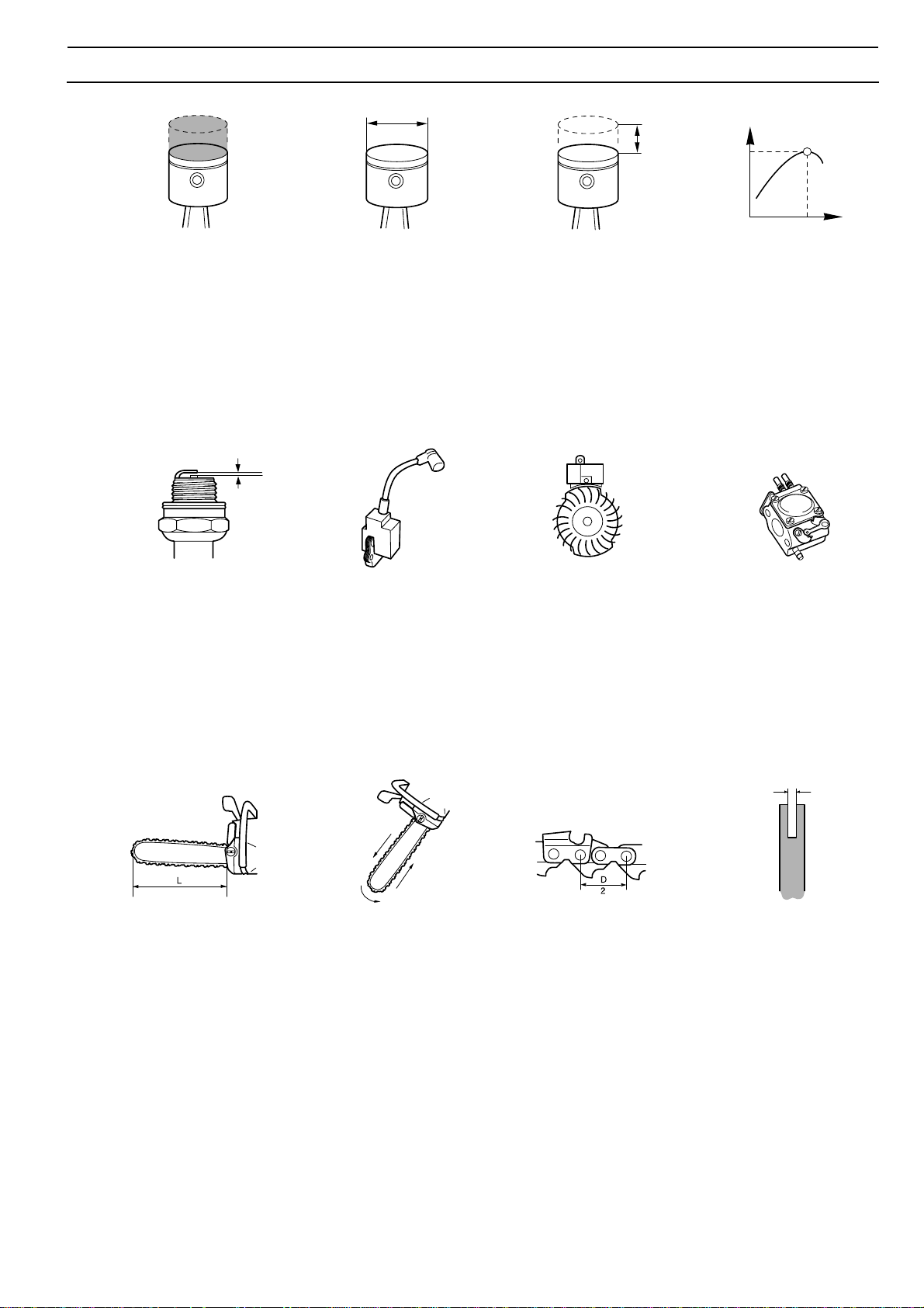
Spark plug gap Ignition system Air gap Carburettor type
385XP 0,5/0,02 FHP/CD 0.30mm/X Tilotson HS 290
3
/5.2 54mm/2.1" 3,7/1,5 4.6/6.3, 9600rpm
mm/inch mm/inch
Guide bar length Chain speed at max. Chain pitch Drive link
power and 9600 rpm
cm/inch m/s mm/inch mm/inch
385XP 45-72/18-28 21,4 9,52/3,8 1,5/0,058
English – 6
www.mymowerparts.com

For Husqvarna Parts Call 606-678-9623 or 606-561-4983
TECHNICAL D ATA
Idling speed Engage speed Max. speed Spark plug
rpm rpm rpm
385XP 2 700 3500 13000 Champion RCJ 7Y
Fuel tank volume Oil pump capacity Oil tank volume Automatic oil pump
Litres/US pint cm
385XP 0,90/1,9 4-20/xx rpm 0,50/1,1 Yes
Weight without bar and chain Weight with bar and chain Hand grip heater Electric carburettor heater
kg/lbs kg/lbs Watts/rpm Watts/rpm
385XP XP 7.0/15.4 XP20" 8.4kg/18.5 65/10000 Yes
XPG 7.2/15.9
3
/min Litres/US pint
www.mymowerparts.com
English – 7

For Husqvarna Parts Call 606-678-9623 or 606-561-4983
SERVICE TOOLS
1 2 4 5
3
67 9
8
10 11
13
12
14
www.mymowerparts.com
English – 8

For Husqvarna Parts Call 606-678-9623 or 606-561-4983
SERVICE TOOLS
15 16 17
18 19 20
The tools listed here are service
tools intended for use on the
chainsaw in question. In addition to
these tools, a standard set of hand
tools is required.
Item Description Used for Order No.
1 Piston stop Locking the crankshaft 502 54 15-01
2 Cover plate, inlet Sealing the intake manifold 502 54 05-01
3 Cover plate, e xhaust Sealing the exhaust port 502 71 39-01
4 Pressure tester Produce pressure when
leakage testing 502 50 38-01
5 Extractor Dismantling the crankshaft 502 51 61-01
6 Puller Remo ving bearings from
the crankshaft 504 90 90-01
7 Holding tool Dismantling of the flywheel 502 51 49-01
8 Puller Dismantling of the flywheel 502 50 26-01
9 Piston assembly set Assembling the piston 502 50 70-01
10 Assembly tool Assembling the crankshaft 502 50 30-17
11 Extractor Removing seal on flywheel side 502 50 55-01
12 Feeler gauges, air gap Adjustment of the ignition module 502 51 34-02
13 Tachometer Adjusting the carburettor 502 71 14-01
14 T est spark plug Checking the ignition module 502 71 13-01
15 Clutch tool Assembling and dismantling 502 52 22-01
of centrifugal clutch
16 Assembly bar Assembly of the spark plug guard 502 50 06-01
17 Hook for the fuel filter Lifting out the fuel filter 502 50 83-01
18 Assembly fixture Assembling the chain sa w 502 51 02-01
19 Hexagonal screwdriver ,
3 mm For M-4 screws 502 50 86-01
19 Hexagonal screwdriver ,
4 mm For M-5 screws 502 50 87-01
19 Hexagonal screwdriver ,
4 mm For M-6 screws 502 50 88-01
20 Allen key, 3 mm For M-4 screws 502 50 19-01
20 Allen key, 4 mm For M-5 screws 502 50 18-01
20 Allen key, 5 mm For M-6 screws 502 50 64-01
www.mymowerparts.com
English – 9

For Husqvarna Parts Call 606-678-9623 or 606-561-4983
TROUBLE SHOOTING
Trouble shooting chart
The different faults that can occur on the chainsaw are
divided into four groups as follows. Within each group
possible operating faults are listed to the left while the
probable fault alternatives are listed to the right. The most
likely fault is listed first, etc.
Starting
Idling (low speed) (continued)
Difficult to start
Carburettor leaks fuel
Floods when engine is
not running
Idling (low speed)
Does not idle
Adjust the L-screw
Air filter blocked
Choke does not work
Worn choke axle
Worn choke valv e
Blocked fuel filter
Blocked fuel line
Piston ring seized
Blocked impulse channel
Loose or faulty fuel pipe
Hole in diaphragm
Worn needle/needle tip
Control system sticking
Control system set too high
Leaking control system (air or
fuel)
Loose cover on carburettor
pump side
Worn needle/needle tip
Control system set too high
Control system sticking
Adjust the L-screw
Leaking intake hose (rubber)
Loose carburettor mounting
Loose or faulty fuel pipe
Blocked fuel filter
Blocked fuel line
Tank ventilator blocked
Throttle valve axle stiff
Throttle wire sticks
Defective throttle return spring
Bent valve axle stop
Faulty diffuser jet
Idles with closed L-screw
Uneven idling
L-screw requires
constant adjustment
Too much fuel when idling
Worn needle/needle tip
Leaking diaphragm/cover plate
Control system sticking
Worn lever arm in the control
system
Faulty diffuser jet
Blocked fuel filter
Blocked fuel line
Leaking intake hose (rubber)
Loose carburettor mounting
Worn throttle valve axle
Loose throttle valve screw
Worn throttle valve
Control system sticking
Leaking control system (air or
fuel)
Worn centre knob in control
system
Hole in diaphragm
Leaking diaphragm/cover plate
Leaking crankcase
Blocked fuel line
Control system set too high
Control system sticking
Leaking control system (air or
fuel)
Leaking diaphragm/cover plate
Faulty diffuser jet
Leaking crankcase
Control system set too high
Control system sticking
Damaged control system
Worn needle/needle tip
Leaking diaphragm/cover plate
Incorrectly fitted control system
Too rich idling
Adjust the L-screw
Worn needle/needle tip
Control system set too high
Worn lever arm in the control
system
Leaking diaphragm/cover plate
Control system sticking
English – 10
www.mymowerparts.com

For Husqvarna Parts Call 606-678-9623 or 606-561-4983
TROUBLE SHOOTING
High speed
Will not run at full
throttle
Low power
Adjust H-screw
Blocked air filter
T ank v entilator bloc ked
Blocked fuel filter
Blocked fuel line
Loose or faulty fuel pipe
Impulse channel leaking
Blocked impulse channel
Cover on carburettor’s pump
side is loose
Faulty pump diaphragm
Leaking intake hose (rubber)
Loose carburettor mounting
Control system set too low
Damaged control system
Incorrectly fitted control system
Leaking diaphragm/cover plate
Control system sticking
Blocked muffler
Adjust H-screw
T ank v entilator bloc ked
Blocked fuel filter
Impulse channel leaking
Blocked impulse channel
Cover on carburettor’s pump
side is loose
Faulty pump diaphragm
Blocked air filter
Control system sticking
Leaking control system
(air or fuel)
Control system incorrectly
assembled
Loose diaphragm
Hole in diaphragm
Leaking diaphragm/cover plate
Acceleration and retardation
Does not accelerate
Engine stops when
throttle released
Too rich acceleration
Adjust the L-screw
Adjust the H-screw
Blocked air filter
Tank ventilator blocked
Blocked fuel filter
Blocked fuel line
Loose or faulty fuel pipe
Blocked impulse channel
Cover on carburettor’s pump
side is loose
Faulty pump diaphragm
Leaking intake hose (rubber)
Loose carburettor mounting
Control system set too low
Incorrectly fitted control system
Control system sticking
Faulty diffuser jet
Blocked muffler
Adjust the L-screw
Adjust the H-screw
Faulty pump diaphragm
Control system set too high
Control system sticking
Faulty diffuser jet
Adjust the L-screw
Adjust the H-screw
Blocked air filter
Faulty pump diaphragm
Faulty diffuser jet
Will not “f our stroke”
T ank v entilator bloc ked
Blocked fuel filter
Blocked fuel line
Loose or faulty fuel pipe
Impulse channel leaking
Blocked impulse channel
Cover on carburettor’s pump
side is loose
Faulty pump diaphragm
Leaking intake hose (rubber)
Loose carburettor mounting
Control system set too low
Leaking control system (air or
fuel)
Control system incorrectly
assembled
Loose diaphragm
Hole in diaphragm
Leaking diaphragm/cover plate
Trouble shooting methods
In addition to faults given in the above schematic, trouble
shooting can be carried out on a specific component or
specific chainsaw system. The different procedures are
described in respective sections and are as follows:
1. Pressure testing the carburettor . See page 35.
2. Pressure testing the crankcase
and cylinder. See page 44.
3. Pressure testing the decompression
valve . See page 42.
4. Checking of the chain brake. See page 16.
www.mymowerparts.com
English – 11

For Husqvarna Parts Call 606-678-9623 or 606-561-4983
SER VICE D ATA
●
●
15
14
10
10
●
5
■
▲
●
▲
8
8
Key to diagrams
The figures next to parts screwed on indicate
the tightening torque Nm.
▲ = Lubricate with two-stroke oil.
■ = Lubricate with chain oil.
● = Lubricate with grease.
www.mymowerparts.com
●
6
English – 12

For Husqvarna Parts Call 606-678-9623 or 606-561-4983
SER VICE D ATA
1,5
4
15
▲
▲
10
15
10
4
6
6
4
35
www.mymowerparts.com
▲
4
●
4
English – 13
For Husqvarna Parts Call 606-678-9623 or 606-561-4983
SAFETY EQUIPMENT
Chain brake
Dismantling
1. Dismantle the following parts first:
• Chain and bar. See the Operator Guide.
• Centrifugal clutch. See page 23.
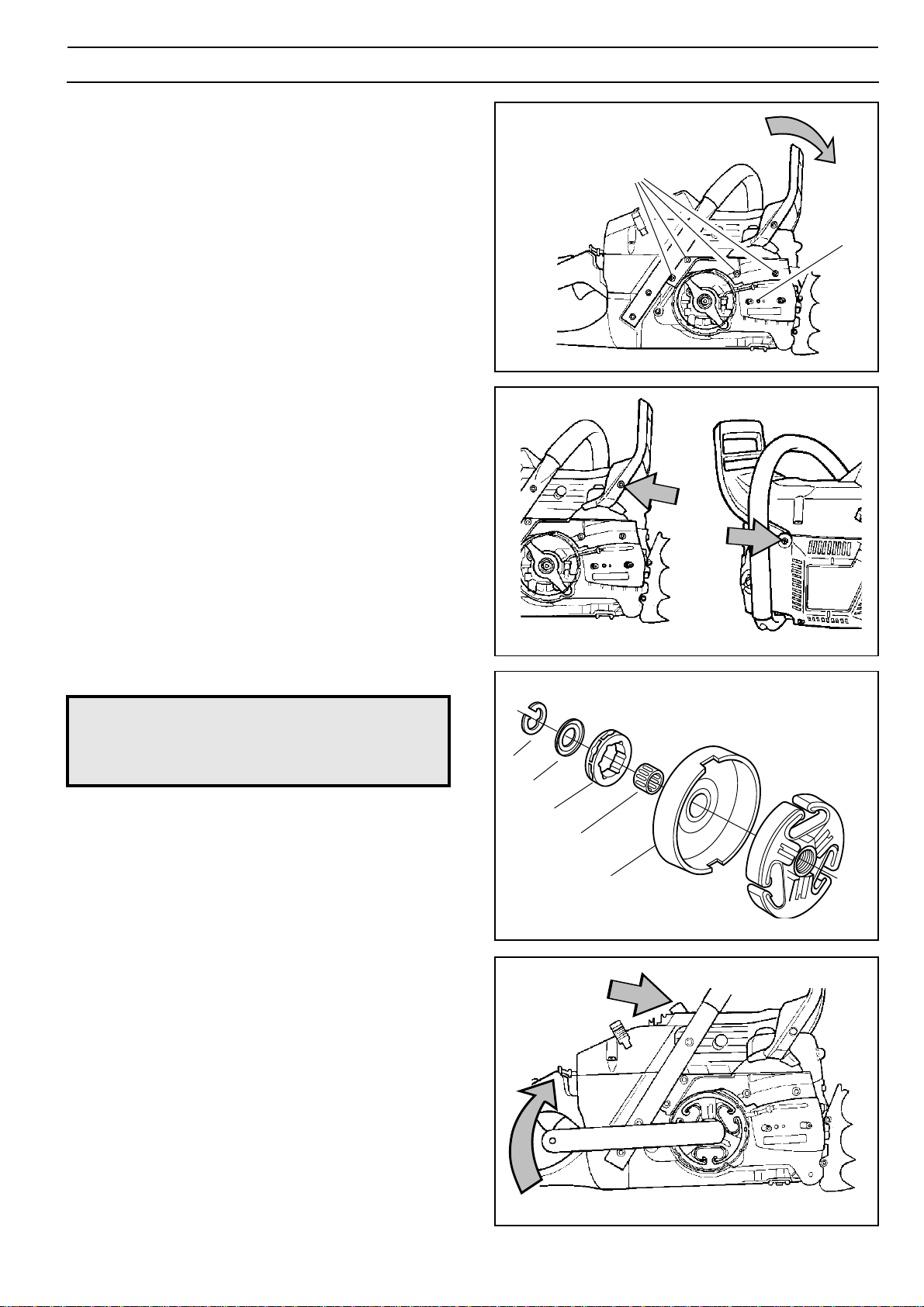
2. Push the hand guard forward so that the chain brak e
is on. See fig. 1.
3. Remove the hand guard, two scre ws. Note the sleeve
on the starter side. See fig. 2.
4. Remove the chain guide-plate (A). See fig. 1.
5. Remove the loc king ring (C) with washer (D) and lift up
the clutch drum (E) with needle bearing (F) and chain
drive sprocket (G). See fig. 3.
6. Remove the spark plug and fit the piston stop .
Remove the clutch with the clutch tool.
Note – left-hand thread. Screw in the direction of the arrow
as in fig. 4.
7. Remove the f our screws (B) and the cover over the chain
brake mechanism. See fig. 1.
B
A
Fig. 1
Fig. 2
WARNING!
!
8. Press down the retaining bush (C fig. 5) while releasing
the lever (D fig. 5) with a screwdriver.
9. Remove the pressure spring by freeing the back end
with a screw driver . See fig. 6.
10.Remov e the toggle joint (E) with attached brak e strap .
See fig. 6.
11.Remov e the br ake strap from the toggle joint.
12.Take out the retaining bush (C) with spring. See fig. 5.
Check that the brake is on. Otherwise
the pressure spring can fly out and
cause personal injury.
C
D
G
F
E
Fig. 3
Fig. 4
www.mymowerparts.com
English – 14

For Husqvarna Parts Call 606-678-9623 or 606-561-4983
SAFETY EQUIPMENT
Inspection
Clean and inspect all parts.
The thickness of the brake strap must no where be less
than 0.8 mm. See fig. 7.
Assembly
Assemble the chain brake as f ollows:
1. Fit the toggle joint and brake strap . See fig. 7.
2. Grease the moving parts of the toggle joint (E) and fit
the unit on the chain saw . See fig. 8.
WARNING!
!
Compress the spring with special tool 502 50 67-01
and press it down with your thumb .
3. Grease and fit the lever (D). See fig. 5.
Ensure that the spring does not fly out
and cause personal injury. Wear
protective glasses.
D
C
Fig. 5
E
4. Grease and fit the retaining bush (C) with spring.
See fig. 5.
5. Fit the cover ov er the chain brak e mechanism. Four
bolts (B). Tighten the bolts to 4 Nm. See fig. 1.
6. Fit the chain guide-plate with bolt (A). See fig. 1.
7. Fit the hand guard with the sleeve on the starter side.
See fig. 2.
8. Push back the hand guard so that the chain brake
is in the off position.
9. Check that the brake strap is correctly positioned in the
recess (F) in the crankcase. See fig. 8.
10.Fit the clutch hub on the crankshaft and tighten with
the clutch tool.
Note – left-hand thread! See fig. 9.
11.Remov e the piston stop and fit the spark plug and put
on the ignition cable.
12.Grease in the needle bearing bef ore fitting. Fit the
clutch drum (E) with needle bearing (F) and chain drive
sprocket (G). See fig. 3.
Fig. 6
Fig. 7
Fig. 8
Min. 0.8 mm
E
C
F
13.Fit the washer (D) and loc king ring (C). See fig. 3.
14.Fit the cylinder cov er , chain and bar. See Operator
Guide.
www.mymowerparts.com
Fig. 9
English – 15
 Loading...