

Page 1

HP Scanjet N9120
Service Manual
Page 2

Page 3

HP Scanjet N9120
Service Manual
Page 4

Copyright information
Safety information
Trademark credits
© 2008 Copyright Hewlett-Packard
Development Company, L.P.
Reproduction, adaptation, or translation
without prior written permission is prohibited,
except as allowed under the copyright laws.
The information contained herein is subject
to change without notice.
The only warranties for HP products and
services are set forth in the express warranty
statements accompanying such products
and services. Nothing herein should be
construed as constituting an additional
warranty. HP shall not be liable for technical
or editorial errors or omissions contained
herein.
Part number L2683-90022
Edition 1, 7/2008
WARNING!
Potential Shock Hazard
Always follow basic safety precautions when
using the product to reduce risk of injury from
fire or electric shock.
Read and understand all instructions in the
user guide.
Observe all warnings and instructions
marked on the product.
Use only a grounded electrical outlet when
connecting the product to a power source. If
you do not know whether the outlet is
grounded, check with a qualified electrician.
Do not touch the contacts on the end of any
of the sockets on the product. Replace
damaged cords immediately.
Unplug the product from wall outlets before
cleaning.
Do not install or use the product near water
or when you are wet.
Install the product securely on a stable
surface.
Microsoft(r), Windows(r), and Windows(r) XP
are U.S. registered trademarks of Microsoft
Corporation.
Windows Vista® is either a registered
trademark or trademark of Microsoft
Corporation in the United States and/or other
countries.
ENERGY STAR and the ENERGY STAR
mark are registered U.S. marks.
Install the product in a protected location
where no one can step on or trip over the
power cord and where the power cord will not
be damaged.
Page 5

Table of contents
1 Product basics
Quick access to product information .................................................................................................... 2
Product basics ...................................................................................................................................... 3
Product features .................................................................................................................. 3
Product walkaround ............................................................................................................. 4
Front and right-side view ..................................................................................... 4
Back view ............................................................................................................ 5
Side view (left) ..................................................................................................... 5
Model and serial numbers ................................................................................... 6
Control-panel walkaround .................................................................................................... 7
Supported product software ................................................................................................. 8
Supported operating systems ............................................................................. 8
Supported scanner drivers .................................................................................. 8
Supported scanner-management software ......................................................... 8
System requirements ........................................................................................................................... 9
Paper handling ................................................................................................................................... 10
ADF specifications ............................................................................................................. 10
Media specifications .......................................................................................................... 10
Media to avoid ................................................................................................................... 11
2 Installation and configuration
Prepare the site .................................................................................................................................. 14
Unpack the device .............................................................................................................................. 15
Install the software ............................................................................................................................. 19
3 Manage and maintain
Manage supplies ................................................................................................................................ 22
HP Scanner Tools Utility scanner maintenance information .............................................. 22
Parts life expectancy .......................................................................................................... 22
Clean the product ............................................................................................................................... 23
Clean the exterior .............................................................................................................. 23
Clean the ADF ................................................................................................................... 24
Clean the scanner glass .................................................................................................... 27
Clean the fan filters ............................................................................................................ 28
ENWW iii
Page 6

4 Theory of operation
Basic operation ................................................................................................................................... 30
Modes and control-panel indicators ................................................................................................... 31
Circuit board assemblies .................................................................................................................... 32
Fans ................................................................................................................................................... 33
ADF feed system ................................................................................................................................ 34
Sensors .............................................................................................................................. 34
Motors ................................................................................................................................ 35
Service block diagram ........................................................................................................................ 36
5 Removal and replacement
Removal and replacement strategy .................................................................................................... 38
General cautions during removal and replacement ........................................................... 38
Electrostatic discharge ....................................................................................................... 38
Required tools .................................................................................................................... 39
Cleaning supplies .............................................................................................................. 39
Screws and fasteners ........................................................................................................ 39
Before performing service .................................................................................................. 39
After performing service ..................................................................................................... 40
User-replaceable parts ....................................................................................................................... 41
Imprinter cartridge .............................................................................................................. 42
Fan filters ........................................................................................................................... 44
ADF base reflector ............................................................................................................. 45
Pickup-roller assembly ....................................................................................................... 47
Separation-pad assembly .................................................................................................. 49
External covers ................................................................................................................................... 51
Scanner control-panel cover .............................................................................................. 52
Scanner back-filter cover ................................................................................................... 53
Scanner right-filter cover .................................................................................................... 53
ADF front cover .................................................................................................................. 54
ADF back cover ................................................................................................................. 57
Scanner back cover ........................................................................................................... 59
Automatic document feeder FRUs ..................................................................................................... 60
Automatic document feeder (ADF) .................................................................................... 62
Reinstall the ADF base reflector ....................................................................... 46
Reinstall the pickup-roller assembly .................................................................. 48
Reinstall the separation-pad assembly ............................................................. 50
Reinstall the ADF .............................................................................................. 66
ADF height adjustment ...................................................................................... 70
NVRAM data management ............................................................................... 73
Repair menu ..................................................................................... 73
Repair menu options ........................................................................ 74
Replacement scenarios .................................................................... 75
iv ENWW
Page 7

NVRAM data file examples ............................................................... 82
NVRAM content adjustment ............................................................. 83
Download factory NVRAM data ........................................................ 84
Backup current NVRAM data ........................................................... 87
Repair NVRAM data ......................................................................... 89
Adjust NVRAM counter items ........................................................... 94
Align the ADF .................................................................................................... 96
Create the factory calibration data for ADF-A ................................................... 99
ADF motor fan ................................................................................................................. 101
ADF carriage fan .............................................................................................................. 102
ADF input-tray lift-motor assembly .................................................................................. 103
ADF exit-motor assembly ................................................................................................ 104
ADF feed-motor assembly ............................................................................................... 108
Reinstall the ADF feed-motor drive belt .......................................................... 110
Reinstall the ADF feed-motor assembly .......................................................... 111
ADF pick-motor assembly ................................................................................................ 114
Reinstall the ADF pick-motor assembly .......................................................... 116
Upper multi-pick sensor PCA ........................................................................................... 119
Lower multi-pick sensor PCA ........................................................................................... 121
ADF controller PCA ......................................................................................................... 123
Imprinter PCA .................................................................................................................. 125
Reinstall the imprinter PCA ............................................................................. 126
Input-tray sensor .............................................................................................................. 129
Flatbed scan position sensor ........................................................................................... 130
Reinstall the flatbed scan position sensor ....................................................... 131
Exit 1 sensor .................................................................................................................... 133
Exit 2 sensor .................................................................................................................... 134
Pick-up roller sensor ........................................................................................................ 135
Elevator arm sensor ......................................................................................................... 137
Background solenoid sensor ........................................................................................... 138
Paper-present sensor ...................................................................................................... 139
Registration sensor .......................................................................................................... 140
Jam door 1 sensor ........................................................................................................... 141
Jam door 2 sensor ........................................................................................................... 142
Jam door 3 sensor ........................................................................................................... 143
Imprinter paper-present sensor ....................................................................................... 144
ADF scan position sensor ................................................................................................ 146
ADF bottom corner outer paper path guide ..................................................................... 147
ADF bottom corner inner paper path guide ..................................................................... 149
ADF cal-strip assembly .................................................................................................... 150
Reinstall the cal-strip assembly ....................................................................... 152
ADF exit inner paper path guide ...................................................................................... 156
ADF top corner inner paper path guide ........................................................................... 159
Lower multi-pick sensor cover ......................................................................................... 160
ENWW v
Page 8

Flatbed scan position sensor arm .................................................................................... 162
Reinstall the flatbed scan position sensor arm ................................................ 163
Exit 1 sensor arm ............................................................................................................. 165
Exit 2 sensor arm ............................................................................................................. 166
Paper-present-sensor arm ............................................................................................... 168
Input-tray-elevator arm .................................................................................................... 169
Registration sensor arm ................................................................................................... 172
Scan position sensor arm ................................................................................................ 174
Pick-up roller spring ......................................................................................................... 175
Separation-pad spring ..................................................................................................... 176
ADF input-tray assembly ................................................................................................. 177
ADF output tray ................................................................................................................ 17 9
Reinstall the ADF output tray .......................................................................... 181
Pickup-roller cover ........................................................................................................... 183
ADF hinge limiters ........................................................................................................... 185
ADF jam door 3 ................................................................................................................ 186
Paper present sensor and imprinter PCA holder ............................................................. 188
ADF shingle wall .............................................................................................................. 190
A4 paper-stop .................................................................................................................. 193
ADF background-solenoid assembly ............................................................................... 194
Reinstall the ADF background-solenoid assembly .......................................... 197
Imprinter carriage and FFC .............................................................................................. 199
Flatbed scanner FRUs ..................................................................................................................... 201
Flatbed ............................................................................................................................. 202
Scanner carriage-motor fan ............................................................................................. 203
Scanner carriage fan ....................................................................................................... 206
Scanner carriage motor ................................................................................................... 208
Control-panel PCA ........................................................................................................... 211
Scanner controller PCA ................................................................................................... 213
Power-supply PCA ........................................................................................................... 216
Scanner-glass assembly .................................................................................................. 220
ADF power-cable assembly ............................................................................................. 221
Carriage-motor cable ....................................................................................................... 223
Power switch and power receptacle assembly ................................................................ 224
6 Solve problems
Troubleshooting process .................................................................................................................. 228
Pre-troubleshooting checklist ........................................................................................................... 229
Basic troubleshooting checks ........................................................................................................... 230
Power-on checks ............................................................................................................. 231
LED diagnostics .............................................................................................. 232
Check the USB connection ............................................................................. 233
Uninstall and then reinstall the HP Scanjet utilities ......................................... 233
vi ENWW
Page 9

Control-panel buttons ...................................................................................... 234
Control-panel buttons diagnostics .................................................. 234
Locked control-panel buttons ......................................................... 234
Troubleshooting diagnostic software ................................................................................................ 235
Main screen ..................................................................................................................... 235
Scan dialog box ............................................................................................... 237
Sensor check dialog box ................................................................................. 239
Control panel check dialog box ....................................................................... 244
ADF feed test dialog box ................................................................................. 246
Actuators dialog box ........................................................................................ 248
NVRAM dialog box .......................................................................................... 251
Update dialog box ........................................................................................... 253
Repair menu .................................................................................................... 254
Version information dialog box ........................................................................ 255
Diagrams ......................................................................................................................... 256
Component locator diagrams .......................................................................... 256
Major components .......................................................................... 256
ADF motors and fans ...................................................................... 258
Printed circuit assemblies ............................................................... 260
Image-quality troubleshooting tools ................................................................................. 262
Repetitive-image-defect ruler .......................................................................... 262
Computer-display error messages ................................................................................................... 263
Computer-display error messages ................................................................................... 263
Solve paper-handling problems ........................................................................................................ 267
Jams ................................................................................................................................ 267
Common causes of jams ................................................................................. 267
Solve common ADF jams ................................................................................ 268
Clear jams from the ADF ................................................................................. 269
The bottom of the scanned image is cut off ..................................................................... 272
Scan extra long documents ............................................................................. 272
Disable misfeed (multipick) detection .............................................................................. 272
ADF does not feed paper ................................................................................................. 273
Solve image-quality problems .......................................................................................................... 274
Image defects .................................................................................................................. 274
Set the background color for scans from the ADF ........................................................... 276
Filter out color from a document (color dropout) .............................................................. 277
Solve performance problems ........................................................................................................... 278
Solve connectivity problems ............................................................................................................. 281
Solve direct-connect problems ........................................................................................ 281
7 Parts and diagrams
Ordering parts and supplies ............................................................................................................. 284
Service part numbers ....................................................................................................................... 285
ENWW vii
Page 10

HP Scanjet N9120 documentation ................................................................................... 285
Imprinter cartridges .......................................................................................................... 285
Power Cords .................................................................................................................... 286
Maintenance kits .............................................................................................................. 286
Field replaceable units (FRUs) ........................................................................................ 287
How to use the parts diagrams and lists .......................................................................................... 289
ADF components .............................................................................................................................. 290
Flatbed scanner assemblies ............................................................................................................. 318
Alphabetical parts list ....................................................................................................................... 336
Numerical parts list ........................................................................................................................... 344
Appendix A Service and support
Hewlett-Packard limited warranty statement .................................................................................... 354
Customer self repair warranty service .............................................................................................. 355
Repack the product .......................................................................................................................... 356
Appendix B Specifications
Physical specifications ..................................................................................................................... 360
Electrical specifications .................................................................................................................... 360
Acoustic emissions ........................................................................................................................... 360
Power consumption specifications ................................................................................................... 360
Environmental specifications ........................................................................................................... 361
Appendix C Regulatory information
Regulatory Model Identification Number .......................................................................................... 364
Materials disposal ............................................................................................................................. 364
Disposal of waste equipment by users in private households in the European Union ..................... 364
Country/region specific statements .................................................................................................. 364
Korean regulatory ............................................................................................................ 364
Index ................................................................................................................................................................. 365
viii ENWW
Page 11

List of tables
Table 1-1 Product guides ................................................................................................................................... 2
Table 1-2 Product specifications ........................................................................................................................ 3
Table 1-3 Control-panel features ........................................................................................................................ 7
Table 1-4 ADF specifications ........................................................................................................................... 10
Table 1-5 Media specifications ......................................................................................................................... 10
Table 2-1 Box contents .................................................................................................................................... 17
Table 3-1 Replacement guidelines ................................................................................................................... 22
Table 4-1 Main assemblies .............................................................................................................................. 30
Table 4-2 Modes and control-panel indicators ................................................................................................. 31
Table 4-3 Circuit board assemblies .................................................................................................................. 32
Table 4-4 Sensors ............................................................................................................................................ 34
Table 6-1 Initial troubleshooting checklist ...................................................................................................... 229
Table 6-2 Control-panel LEDs ........................................................................................................................ 232
Table 6-3 Main screen .................................................................................................................................... 235
Table 6-4 Scan dialog box .............................................................................................................................. 237
Table 6-5 Sensor in motion tab ...................................................................................................................... 239
Table 6-6 Sensor tab ...................................................................................................................................... 241
Table 6-7 Control panel check dialog box ...................................................................................................... 244
Table 6-8 ADF feed test dialog box ................................................................................................................ 246
Table 6-9 Actuators dialog box ....................................................................................................................... 249
Table 6-10 Repair menu ................................................................................................................................. 254
Table 6-11 Major components (1 of 3) ........................................................................................................... 256
Table 6-12 Major components (2 of 3) ........................................................................................................... 257
Table 6-13 Major components (3 of 3) ........................................................................................................... 257
Table 6-14 ADF motors and fans (1 of 2) ....................................................................................................... 258
Table 6-15 ADF motors and fans (2 of 2) ....................................................................................................... 259
Table 6-16 Scanner motors and fans ............................................................................................................. 259
Table 6-17 ADF controller PCA ...................................................................................................................... 260
Table 6-18 Scanner PCAs .............................................................................................................................. 261
Table 6-19 Repetitive defects ......................................................................................................................... 262
Table 6-20 ISIS driver communicated message ............................................................................................ 263
Table 6-21 SDSS error message displayed ................................................................................................... 264
Table 6-22 Image defect examples ................................................................................................................ 274
Table 6-23 Solve performance problems ....................................................................................................... 278
ENWW ix
Page 12

Table 7-1 HP Scanjet N9120 documentation ................................................................................................. 285
Table 7-2 Imprinter cartridges ........................................................................................................................ 285
Table 7-3 Power cords ................................................................................................................................... 286
Table 7-4 Maintenance kits ............................................................................................................................ 286
Table 7-5 Field replaceable units (FRUs) ....................................................................................................... 287
Table 7-6 ADF assemblies (1 of 14) ............................................................................................................... 291
Table 7-7 ADF assemblies (2 of 14) ............................................................................................................... 293
Table 7-8 ADF assemblies (3 of 14) ............................................................................................................... 295
Table 7-9 ADF assemblies (4 of 14) ............................................................................................................... 297
Table 7-10 ADF assemblies (5 of 14) ............................................................................................................. 299
Table 7-11 ADF assemblies (6 of 14) ............................................................................................................. 301
Table 7-12 ADF assemblies (7 of 14) ............................................................................................................. 303
Table 7-13 ADF assemblies (8 of 14) ............................................................................................................. 305
Table 7-14 ADF assemblies (9 of 14) ............................................................................................................. 307
Table 7-15 ADF assemblies (10 of 14) ........................................................................................................... 309
Table 7-16 ADF assemblies (11 of 14) ........................................................................................................... 311
Table 7-17 ADF assemblies (12 of 14) ........................................................................................................... 313
Table 7-18 ADF assemblies (13 of 14) ........................................................................................................... 315
Table 7-19 ADF assemblies (14 of 14) ........................................................................................................... 317
Table 7-20 Flatbed scanner assemblies (1 of 9) ............................................................................................ 319
Table 7-21 Flatbed scanner assemblies (2 of 9) ............................................................................................ 321
Table 7-22 Flatbed scanner assemblies (3 of 9) ............................................................................................ 323
Table 7-23 Flatbed scanner assemblies (4 of 9) ............................................................................................ 325
Table 7-24 Flatbed scanner assemblies (5 of 9) ............................................................................................ 327
Table 7-25 Flatbed scanner assemblies (6 of 9) ............................................................................................ 329
Table 7-26 Flatbed scanner assemblies (7 of 9) ............................................................................................ 331
Table 7-27 Flatbed scanner assemblies (8 of 9) ............................................................................................ 333
Table 7-28 Flatbed scanner assemblies (9 of 9) ............................................................................................ 335
Table 7-29 Alphabetical parts list ................................................................................................................... 336
Table 7-30 Numerical parts list ....................................................................................................................... 344
Table B-1 Physical specifications ................................................................................................................... 360
Table B-2 Electrical specifications .................................................................................................................. 360
Table B-3 HP Scanjet N9120, ........................................................................................................................ 360
Table B-4 Environmental specifications ........................................................................................................ 361
x ENWW
Page 13

List of figures
Figure 1-1 Front and right-side view ................................................................................................................... 4
Figure 1-2 Back view .......................................................................................................................................... 5
Figure 1-3 Side view (left) .................................................................................................................................. 5
Figure 1-4 Model and serial number (1 of 2) ...................................................................................................... 6
Figure 1-5 Model and serial number (2 of 2) ...................................................................................................... 6
Figure 1-6 Control-panel features ...................................................................................................................... 7
Figure 2-1 Site dimensions ............................................................................................................................... 14
Figure 2-2 Unpack the device (1 of 9) .............................................................................................................. 15
Figure 2-3 Unpack the device (2 of 9) .............................................................................................................. 15
Figure 2-4 Unpack the device (3 of 9) .............................................................................................................. 16
Figure 2-5 Unpack the device (4 of 9) .............................................................................................................. 16
Figure 2-6 Unpack the device (5 of 9) .............................................................................................................. 17
Figure 2-7 Unpack the device (6 of 9) .............................................................................................................. 17
Figure 2-8 Unpack the device (7 of 9) .............................................................................................................. 17
Figure 2-9 Unpack the device (8 of 9) .............................................................................................................. 18
Figure 2-10 Unpack the device (9 of 9) ............................................................................................................ 18
Figure 2-11 Electrical connection ..................................................................................................................... 19
Figure 2-12 USB connection ............................................................................................................................ 19
Figure 2-13 Power switch ................................................................................................................................. 20
Figure 3-1 Clean the ADF (1 of 5) .................................................................................................................... 24
Figure 3-2 Clean the ADF (2 of 5) .................................................................................................................... 25
Figure 3-3 Clean the ADF (3 of 5) .................................................................................................................... 25
Figure 3-4 Clean the ADF (4 of 5) .................................................................................................................... 26
Figure 3-5 Clean the ADF (5 of 5) .................................................................................................................... 26
Figure 3-6 Clean the scanner glass ................................................................................................................. 27
Figure 3-7 Clean the scanner fan filters (1 of 2) ............................................................................................... 28
Figure 3-8 Clean the scanner fan filters (2 of 2) ............................................................................................... 28
Figure 4-1 Sensors ........................................................................................................................................... 34
Figure 4-2 Motors ............................................................................................................................................. 35
Figure 4-3 Service block diagram ..................................................................................................................... 36
Figure 5-1 Phillips and pozidrive screwdriver comparison ............................................................................... 39
Figure 5-2 Remove the imprinter cartridge (1 of 4) .......................................................................................... 42
Figure 5-3 Remove the imprinter cartridge (2 of 4) .......................................................................................... 42
Figure 5-4 Remove the imprinter cartridge (3 of 4) .......................................................................................... 43
ENWW xi
Page 14

Figure 5-5 Remove the imprinter cartridge (4 of 4) .......................................................................................... 43
Figure 5-6 Remove the fan filter (1 of 2) .......................................................................................................... 44
Figure 5-7 Remove the fan filter (2 of 2) .......................................................................................................... 44
Figure 5-8 Remove the ADF base reflector (1 of 2) ......................................................................................... 45
Figure 5-9 Remove the ADF base reflector (2 of 2) ......................................................................................... 45
Figure 5-10 Reinstall the ADF base reflector ................................................................................................... 46
Figure 5-11 Remove the pickup-roller assembly .............................................................................................. 47
Figure 5-12 Reinstall the pickup-roller assembly (1 of 2) ................................................................................. 48
Figure 5-13 Reinstall the pickup-roller assembly (2 of 2) ................................................................................. 48
Figure 5-14 Remove the separation-pad assembly (1 of 3) ............................................................................. 49
Figure 5-15 Remove the separation-pad assembly (2 of 3) ............................................................................. 49
Figure 5-16 Remove the separation-pad assembly (3 of 3) ............................................................................. 50
Figure 5-17 Reinstall the separation-pad assembly ......................................................................................... 50
Figure 5-18 Remove the scanner control-panel cover ..................................................................................... 52
Figure 5-19 Remove the ADF front cover (1 of 5) ............................................................................................ 54
Figure 5-20 Remove the ADF front cover (2 of 5) ............................................................................................ 54
Figure 5-21 Remove the ADF front cover (3 of 5) ............................................................................................ 55
Figure 5-22 Remove the ADF front cover (4 of 5) ............................................................................................ 55
Figure 5-23 Remove the ADF front cover (5 of 5) ............................................................................................ 56
Figure 5-24 Remove the ADF back cover (1 of 3) ............................................................................................ 57
Figure 5-25 Remove the ADF back cover (2 of 3) ............................................................................................ 57
Figure 5-26 Remove the ADF back cover (3 of 3) ............................................................................................ 58
Figure 5-27 Remove the scanner back cover (1 of 2) ...................................................................................... 59
Figure 5-28 Remove the scanner back cover (2 of 2) ...................................................................................... 59
Figure 5-29 Remove the ADF (1 of 8) .............................................................................................................. 62
Figure 5-30 Remove the ADF (2 of 8) .............................................................................................................. 62
Figure 5-31 Remove the ADF (3 of 8) .............................................................................................................. 63
Figure 5-32 Remove the ADF (4 of 8) .............................................................................................................. 63
Figure 5-33 Remove the ADF (5 of 8) .............................................................................................................. 64
Figure 5-34 Remove the ADF (6 of 8) .............................................................................................................. 64
Figure 5-35 Remove the ADF (7 of 8) .............................................................................................................. 65
Figure 5-36 Remove the ADF (8 of 8) .............................................................................................................. 65
Figure 5-37 Reinstall the ADF (1 of 7) .............................................................................................................. 66
Figure 5-38 Reinstall the ADF (2 of 7) .............................................................................................................. 66
Figure 5-39 Reinstall the ADF (3 of 7) .............................................................................................................. 67
Figure 5-40 Reinstall the ADF (4 of 7) .............................................................................................................. 67
Figure 5-41 Reinstall the ADF (5 of 7) .............................................................................................................. 68
Figure 5-42 Reinstall the ADF (6 of 7) .............................................................................................................. 68
Figure 5-43 Reinstall the ADF (7 of 7) .............................................................................................................. 69
Figure 5-44 ADF height adjustment (1 of 6) ..................................................................................................... 70
Figure 5-45 ADF height adjustment (2 of 6) ..................................................................................................... 70
Figure 5-46 ADF height adjustment (3 of 6) ..................................................................................................... 70
Figure 5-47 ADF height adjustment (4 of 6) ..................................................................................................... 71
Figure 5-48 ADF height adjustment (5 of 6) ..................................................................................................... 71
xii ENWW
Page 15

Figure 5-49 ADF height adjustment (6 of 6) ..................................................................................................... 72
Figure 5-50 Repair menu (1 of 11) ................................................................................................................... 73
Figure 5-51 Repair menu (2 of 11) ................................................................................................................... 74
Figure 5-52 Replacement scenario #1 (3 of 11) ............................................................................................... 75
Figure 5-53 Replacement scenario #2 (4 of 11) ............................................................................................... 76
Figure 5-54 Replacement scenario #3 (5 of 11) ............................................................................................... 77
Figure 5-55 Replacement scenario #4 (6 of 7) ................................................................................................. 78
Figure 5-56 Replacement scenario #5 (7 of 11) ............................................................................................... 79
Figure 5-57 Replacement scenario #6 (8 of 11) ............................................................................................... 80
Figure 5-58 Replacement scenario #7 (9 of 11) ............................................................................................... 81
Figure 5-59 Repair menu (10 of 11) ................................................................................................................. 82
Figure 5-60 Repair menu (11 of 11) ................................................................................................................. 83
Figure 5-61 Download factory NVRAM data (1 of 6) ........................................................................................ 84
Figure 5-62 Download factory NVRAM data (2 of 6) ........................................................................................ 84
Figure 5-63 Download factory NVRAM data (3 of 6) ........................................................................................ 85
Figure 5-64 Download factory NVRAM data (4 of 6) ........................................................................................ 85
Figure 5-65 Download factory NVRAM data (5 of 6) ........................................................................................ 86
Figure 5-66 Download factory NVRAM data (6 of 6) ........................................................................................ 86
Figure 5-67 Backup current NVRAM data (1 of 3) ........................................................................................... 87
Figure 5-68 Backup current NVRAM data (2 of 3) ........................................................................................... 87
Figure 5-69 Backup current NVRAM data (3 of 3) ........................................................................................... 88
Figure 5-70 Repair NVRAM data (1 of 5) ......................................................................................................... 89
Figure 5-71 Repair NVRAM data (2 of 5) ......................................................................................................... 90
Figure 5-72 Repair NVRAM data (3 of 5) ......................................................................................................... 91
Figure 5-73 Repair NVRAM data (4 of 5) ......................................................................................................... 92
Figure 5-74 Repair NVRAM data (5 of 5) ......................................................................................................... 93
Figure 5-75 Adjust NVRAM counter items (1 of 2) ........................................................................................... 94
Figure 5-76 Adjust NVRAM counter items (2 of 2) ........................................................................................... 95
Figure 5-77 ADF alignment (1 of 6) .................................................................................................................. 96
Figure 5-78 ADF alignment (2 of 6) .................................................................................................................. 97
Figure 5-79 ADF alignment (3 of 6) .................................................................................................................. 97
Figure 5-80 ADF alignment (4 of 6) .................................................................................................................. 97
Figure 5-81 ADF alignment (5 of 6) .................................................................................................................. 98
Figure 5-82 Create the factory calibration data for ADF-A (1 of 3) .................................................................. 99
Figure 5-83 Create the factory calibration data for ADF-A (2 of 3) .................................................................. 99
Figure 5-84 Create the factory calibration data for ADF-A (3 of 3) ................................................................ 100
Figure 5-85 Remove the ADF motor fan (1 of 2) ............................................................................................ 101
Figure 5-86 Remove the ADF motor fan (2 of 2) ............................................................................................ 101
Figure 5-87 Remove the ADF carriage fan ................................................................................................... 102
Figure 5-88 Remove the ADF input-tray lift-motor assembly (1 of 2) ............................................................. 103
Figure 5-89 Remove the ADF input-tray lift-motor assembly (2 of 2) ............................................................. 103
Figure 5-90 Remove the ADF exit-motor assembly (1 of 7) ........................................................................... 104
Figure 5-91 Remove the ADF exit-motor assembly (2 of 7) ........................................................................... 104
Figure 5-92 Remove the ADF exit-motor assembly (3 of 7) ........................................................................... 105
ENWW xiii
Page 16

Figure 5-93 Remove the ADF exit-motor assembly (4 of 7) ........................................................................... 105
Figure 5-94 Remove the ADF exit-motor assembly (5 of 7) ........................................................................... 106
Figure 5-95 Remove the ADF exit-motor assembly (6 of 7) ........................................................................... 106
Figure 5-96 Remove the ADF exit-motor assembly (7 of 7) ........................................................................... 107
Figure 5-97 Remove the ADF feed-motor assembly (1 of 4) ......................................................................... 108
Figure 5-98 Remove the ADF feed-motor assembly (2 of 4) ......................................................................... 108
Figure 5-99 Remove the ADF feed-motor assembly (3 of 4) ......................................................................... 109
Figure 5-100 Remove the ADF feed-motor assembly (4 of 4) ....................................................................... 109
Figure 5-101 Reinstall the ADF feed-motor drive belt (1 of 3) ....................................................................... 110
Figure 5-102 Reinstall the ADF feed-motor drive belt (2 of 3) ....................................................................... 110
Figure 5-103 Reinstall the ADF feed-motor drive belt (3 of 3) ....................................................................... 111
Figure 5-104 Reinstall the ADF feed-motor assembly (1 of 5) ....................................................................... 111
Figure 5-105 Reinstall the ADF feed-motor assembly (2 of 5) ....................................................................... 112
Figure 5-106 Reinstall the ADF feed-motor assembly (3 of 5) ....................................................................... 112
Figure 5-107 Reinstall the ADF feed-motor assembly (4 of 5) ....................................................................... 113
Figure 5-108 Reinstall the ADF feed-motor assembly (5 of 5) ....................................................................... 113
Figure 5-109 Remove the ADF pick-motor assembly (1 of 5) ........................................................................ 114
Figure 5-110 Remove the ADF pick-motor assembly (2 of 5) ........................................................................ 114
Figure 5-111 Remove the ADF pick-motor assembly (3 of 5) ........................................................................ 115
Figure 5-112 Remove the ADF pick-motor assembly (4 of 5) ........................................................................ 115
Figure 5-113 Remove the ADF pick-motor assembly (5 of 5) ........................................................................ 116
Figure 5-114 Reinstall the ADF pick-motor assembly (1 of 5) ........................................................................ 116
Figure 5-115 Reinstall the ADF pick-motor assembly (2 of 5) ........................................................................ 117
Figure 5-116 Reinstall the ADF pick-motor assembly (3 of 5) ........................................................................ 117
Figure 5-117 Reinstall the ADF pick-motor assembly (4 of 5) ........................................................................ 118
Figure 5-118 Reinstall the ADF pick-motor assembly (5 of 5) ........................................................................ 118
Figure 5-119 Remove the upper multi-pick sensor PCA (1 of 3) ................................................................... 119
Figure 5-120 Remove the upper multi-pick sensor PCA (2 of 3) ................................................................... 120
Figure 5-121 Remove the upper multi-pick sensor PCA (3 of 3) ................................................................... 120
Figure 5-122 Remove the lower multi-pick sensor PCA (1 of 2) .................................................................... 121
Figure 5-123 Remove the lower multi-pick sensor PCA (2 of 2) .................................................................... 122
Figure 5-124 Remove the ADF controller PCA (1 of 2) .................................................................................. 123
Figure 5-125 Remove the ADF controller PCA (2 of 2) .................................................................................. 124
Figure 5-126 Remove the imprinter PCA (1 of 2) ........................................................................................... 125
Figure 5-127 Remove the imprinter PCA (2 of 2) ........................................................................................... 126
Figure 5-128 Reinstall the imprinter PCA (1 of 4) .......................................................................................... 126
Figure 5-129 Reinstall the imprinter PCA (2 of 4) .......................................................................................... 127
Figure 5-130 Reinstall the imprinter PCA (3 of 4) .......................................................................................... 127
Figure 5-131 Reinstall the imprinter PCA (4 of 4) .......................................................................................... 128
Figure 5-132 Remove the input-tray sensor ................................................................................................... 129
Figure 5-133 Remove the flatbed scan position sensor (1 of 2) .................................................................... 130
Figure 5-134 Remove the flatbed scan position sensor (2 of 2) .................................................................... 131
Figure 5-135 Reinstall the flatbed scan position sensor ................................................................................ 131
Figure 5-136 Remove the exit 1 sensor ......................................................................................................... 133
xiv ENWW
Page 17

Figure 5-137 Remove the exit 2 sensor ......................................................................................................... 134
Figure 5-138 Remove the pick-up roller sensor (1 of 4) ................................................................................. 135
Figure 5-139 Remove the pick-up roller sensor (2 of 4) ................................................................................. 135
Figure 5-140 Remove the pick-up roller sensor (3 of 4) ................................................................................. 136
Figure 5-141 Remove the pick-up roller sensor (4 of 4) ................................................................................. 136
Figure 5-142 Remove the elevator arm sensor .............................................................................................. 137
Figure 5-143 Remove the background solenoid sensor (1 of 2) .................................................................... 138
Figure 5-144 Remove the background solenoid sensor (2 of 2) .................................................................... 138
Figure 5-145 Remove the paper-present sensor ........................................................................................... 139
Figure 5-146 Remove the registration sensor ................................................................................................ 140
Figure 5-147 Remove the jam door 1 sensor ................................................................................................. 141
Figure 5-148 Remove jam door 2 sensor ....................................................................................................... 142
Figure 5-149 Remove the jam door 3 sensor ................................................................................................. 143
Figure 5-150 Remove the imprinter paper-present sensor (1 of 2) ................................................................ 144
Figure 5-151 Remove the imprinter paper-present sensor (2 of 2) ................................................................ 145
Figure 5-152 Remove the ADF scan position sensor .................................................................................... 146
Figure 5-153 Remove the ADF bottom corner outer paper path guide (1 of 2) ............................................. 147
Figure 5-154 Remove the ADF bottom corner outer paper path guide (2 of 2) ............................................. 147
Figure 5-155 Reinstall the ADF bottom corner outer paper path guide ......................................................... 148
Figure 5-156 Remove the ADF bottom corner inner paper path guide (1 of 2) .............................................. 149
Figure 5-157 Remove the ADF bottom corner inner paper path guide (2 of 2) .............................................. 149
Figure 5-158 Remove the ADF cal-strip assembly (1 of 5) ............................................................................ 150
Figure 5-159 Remove the ADF cal-strip assembly (2 of 5) ............................................................................ 150
Figure 5-160 Remove the ADF cal-strip assembly (3 of 5) ............................................................................ 151
Figure 5-161 Remove the ADF cal-strip assembly (4 of 5) ............................................................................ 151
Figure 5-162 Remove the ADF cal-strip assembly (5 of 5) ............................................................................ 152
Figure 5-163 Reinstall the ADF cal-strip assembly (1 of 7) ............................................................................ 152
Figure 5-164 Reinstall the ADF cal-strip assembly (2 of 7) ............................................................................ 153
Figure 5-165 Reinstall the ADF cal-strip assembly (3 of 7) ............................................................................ 153
Figure 5-166 Reinstall the ADF cal-strip assembly (4 of 7) ............................................................................ 154
Figure 5-167 Reinstall the ADF cal-strip assembly (5 of 7) ............................................................................ 154
Figure 5-168 Reinstall the ADF cal-strip assembly (6 of 7) ............................................................................ 155
Figure 5-169 Reinstall the ADF cal-strip assembly (7 of 7) ............................................................................ 155
Figure 5-170 Remove the ADF exit inner paper path guide (1 of 4) .............................................................. 156
Figure 5-171 Remove the ADF exit inner paper path guide (2 of 4) .............................................................. 157
Figure 5-172 Remove the ADF exit inner paper path guide (3 of 4) .............................................................. 157
Figure 5-173 Remove the ADF exit inner paper path guide (4 of 4) .............................................................. 158
Figure 5-174 Remove the ADF top corner inner paper path guide (1 of 2) .................................................... 159
Figure 5-175 Remove the ADF top corner inner paper path guide (2 of 2) .................................................... 159
Figure 5-176 Remove the lower multi-pick sensor cover (1 of 3) ................................................................... 160
Figure 5-177 Remove the lower multi-pick sensor cover (2 of 3) ................................................................
Figure 5-178 Remove the lower multi-pick sensor cover (3 of 3) ................................................................... 161
Figure 5-179 Remove the flatbed scan position sensor arm (1 of 2) ............................................................. 162
Figure 5-180 Remove the flatbed scan position sensor arm (2 of 2) ............................................................. 163
... 161
ENWW xv
Page 18

Figure 5-181 Reinstall the flatbed scan position sensor arm (1 of 3) ............................................................. 163
Figure 5-182 Reinstall the flatbed scan position sensor arm (2 of 3) ............................................................. 164
Figure 5-183 Reinstall the flatbed scan position sensor arm (3 of 3) ............................................................. 164
Figure 5-184 Remove the exit 1 sensor arm .................................................................................................. 165
Figure 5-185 Remove the exit 2 sensor arm (1 of 3) ..................................................................................... 166
Figure 5-186 Remove the exit 2 sensor arm (2 of 3) ..................................................................................... 167
Figure 5-187 Remove the exit 2 sensor arm (3 of 3) ..................................................................................... 167
Figure 5-188 Remove the paper-present-sensor arm (1 of 2) ....................................................................... 168
Figure 5-189 Remove the paper-present-sensor arm (2 of 2) ....................................................................... 168
Figure 5-190 Remove the input-tray-elevator arm (1 of 5) ............................................................................. 169
Figure 5-191 Remove the input-tray-elevator arm (2 of 5) ............................................................................. 169
Figure 5-192 Remove the input-tray-elevator arm (3 of 5) ............................................................................. 170
Figure 5-193 Remove the input-tray-elevator arm (4 of 5) ............................................................................. 170
Figure 5-194 Remove the input-tray-elevator arm (5 of 5) ............................................................................. 171
Figure 5-195 Remove the registration sensor arm (1 of 2) ............................................................................ 172
Figure 5-196 Remove the registration sensor arm (2 of 2) ............................................................................ 173
Figure 5-197 Remove the scan position sensor arm (1 of 2) ......................................................................... 174
Figure 5-198 Remove the scan position sensor arm (2 of 2) ......................................................................... 174
Figure 5-199 Remove the pickup-roller spring ............................................................................................... 175
Figure 5-200 Remove the separation-pad spring ........................................................................................... 176
Figure 5-201 Remove the ADF input-tray assembly (1 of 3) .......................................................................... 177
Figure 5-202 Remove the ADF input-tray assembly (2 of 3) .......................................................................... 177
Figure 5-203 Remove the ADF input-tray assembly (3 of 3) .......................................................................... 178
Figure 5-204 Remove the ADF output tray (1 of 3) ........................................................................................ 179
Figure 5-205 Remove the ADF output tray (2 of 3) ........................................................................................ 179
Figure 5-206 Remove the ADF output tray (3 of 3) ........................................................................................ 180
Figure 5-207 Reinstall the ADF output tray (1 of 4) ....................................................................................... 181
Figure 5-208 Reinstall the ADF output tray (2 of 4) ....................................................................................... 181
Figure 5-209 Reinstall the ADF output tray (3 of 4) ....................................................................................... 182
Figure 5-210 Reinstall the ADF output tray (4 of 4) ....................................................................................... 182
Figure 5-211 Remove the pickup-roller cover (1 of 3) .................................................................................... 183
Figure 5-212 Remove the pickup-roller cover (2 of 3) .................................................................................... 183
Figure 5-213 Remove the pickup-roller cover (3 of 3) .................................................................................... 184
Figure 5-214 Remove the ADF hinge limiters ................................................................................................ 185
Figure 5-215 Remove ADF jam door 3 (1 of 4) .............................................................................................. 186
Figure 5-216 Remove ADF jam door 3 (2 of 4) .............................................................................................. 186
Figure 5-217 Remove ADF jam door 3 (3 of 4) .............................................................................................. 187
Figure 5-218 Remove ADF jam door 3 (4 of 4) .............................................................................................. 187
Figure 5-219 Remove the paper present sensor and imprinter PCA holder (1 of 3) ...................................... 188
Figure 5-220 Remove the paper present sensor and imprinter PCA holder (2 of 3) ...................................... 189
Figure 5-221 Remove the paper present sensor and imprinter PCA holder (3 of 3) ...................................... 189
Figure 5-222 Remove the ADF shingle wall (1 of 4) ...................................................................................... 190
Figure 5-223 Remove the ADF shingle wall (2 of 4) ...................................................................................... 191
Figure 5-224 Remove the ADF shingle wall (3 of 4) ...................................................................................... 191
xvi ENWW
Page 19

Figure 5-225 Remove the ADF shingle wall (4 of 4) ...................................................................................... 192
Figure 5-226 Remove the A4 paper-stop (1 of 2) .......................................................................................... 193
Figure 5-227 Remove the A4 paper-stop (2 of 2) .......................................................................................... 193
Figure 5-228 Remove the ADF background-solenoid assembly (1 of 5) ....................................................... 194
Figure 5-229 Remove the ADF background-solenoid assembly (2 of 5) ....................................................... 194
Figure 5-230 Remove the ADF background-solenoid assembly (3 of 5) ....................................................... 195
Figure 5-231 Remove the ADF background-solenoid assembly (4 of 5) ....................................................... 195
Figure 5-232 Remove the ADF background-solenoid assembly (5 of 5) ....................................................... 196
Figure 5-233 Reinstall the ADF background-solenoid assembly (1 of 3 ........................................................ 197
Figure 5-234 Reinstall the ADF background-solenoid assembly (1 of 3) ....................................................... 197
Figure 5-235 Reinstall the ADF background-solenoid assembly (3 of 3) ....................................................... 198
Figure 5-236 Imprinter carriage and FFC (1 of 3) ......................................................................................... 199
Figure 5-237 Imprinter carriage and FFC (2 of 3) .......................................................................................... 199
Figure 5-238 Imprinter carriage and FFC (3 of 3) .......................................................................................... 200
Figure 5-239 Remove the scanner carriage-motor fan (1 of 5) ...................................................................... 203
Figure 5-240 Remove the scanner carriage-motor fan (2 of 5) ...................................................................... 203
Figure 5-241 Remove the scanner carriage-motor fan (3 of 5) ...................................................................... 204
Figure 5-242 Remove the scanner carriage-motor fan (4 of 5) ...................................................................... 204
Figure 5-243 Remove the scanner carriage-motor fan (5 of 5) ...................................................................... 205
Figure 5-244 Remove the scanner carriage fan (1 of 3) ................................................................................ 206
Figure 5-245 Remove the scanner carriage fan (2 of 3) ................................................................................ 206
Figure 5-246 Remove the scanner carriage fan (3 of 3) ................................................................................ 207
Figure 5-247 Remove the scanner carriage motor (1 of 5) ............................................................................ 208
Figure 5-248 Remove the scanner carriage motor (2 of 5) ............................................................................ 208
Figure 5-249 Remove the scanner carriage motor (3 of 5) ............................................................................ 209
Figure 5-250 Remove the scanner carriage motor (4 of 5) ............................................................................ 209
Figure 5-251 Remove the scanner carriage motor (5 of 5) ............................................................................ 210
Figure 5-252 Remove the control-panel PCA (1 of 3) .................................................................................... 211
Figure 5-253 Remove the control-panel PCA (2 of 3) .................................................................................... 211
Figure 5-254 Remove the control-panel PCA (3 of 3) .................................................................................... 212
Figure 5-255 Remove the scanner controller PCA (1 of 4) ............................................................................ 213
Figure 5-256 Remove the scanner controller PCA (2 of 4) ............................................................................ 214
Figure 5-257 Remove the scanner controller PCA (3 of 4) ............................................................................ 214
Figure 5-258 Remove the scanner controller PCA (4 of 4) ............................................................................ 215
Figure 5-259 Remove the power-supply PCA (1 of 6) ................................................................................... 216
Figure 5-260 Remove the power-supply PCA (2 of 6) ................................................................................... 217
Figure 5-261 Remove the power-supply PCA (3 of 6) ................................................................................... 217
Figure 5-262 Remove the power-supply PCA (4 of 6) ................................................................................... 218
Figure 5-263 Remove the power-supply PCA (5 of 6) ................................................................................... 218
Figure 5-264 Remove the power-supply PCA (6 of 6) ................................................................................... 219
Figure 5-265 Remove the scanner-glass assembly (1 of 2) .......................................................................... 220
Figure 5-266 Remove the scanner-glass assembly (2 of 2) .......................................................................... 220
Figure 5-267 Remove the ADF power-cable assembly (1 of 3) ..................................................................... 221
Figure 5-268 Remove the ADF power-cable assembly (2 of 3) ..................................................................... 221
ENWW xvii
Page 20

Figure 5-269 Remove the ADF power-cable assembly (3 of 3) ..................................................................... 222
Figure 5-270 Remove the carriage-motor cable ............................................................................................ 223
Figure 5-271 Remove the power switch and power receptacle assembly (1 of 3) ......................................... 224
Figure 5-272 Remove the power switch and power receptacle assembly (2 of 3) ......................................... 224
Figure 5-273 Remove the power switch and power receptacle assembly (3 of 3) ......................................... 225
Figure 6-1 Control-panel LEDs ....................................................................................................................... 232
Figure 6-2 Main screen .................................................................................................................................. 235
Figure 6-3 Scan dialog box ............................................................................................................................ 237
Figure 6-4 Sensor in motion tab ..................................................................................................................... 239
Figure 6-5 Sensor tab ..................................................................................................................................... 241
Figure 6-6 Control panel check dialog box ..................................................................................................... 244
Figure 6-7 ADF feed test dialog box ............................................................................................................... 246
Figure 6-8 Actuators dialog box ..................................................................................................................... 248
Figure 6-9 Get/SetNVRAMValue(String) tab .................................................................................................. 251
Figure 6-10 Get/SetNVRAMValue(String) tab ................................................................................................ 252
Figure 6-11 Repair menu ............................................................................................................................... 254
Figure 6-12 Version information dialog box ................................................................................................... 255
Figure 6-13 Major components (1 of 3) .......................................................................................................... 256
Figure 6-14 Major components (2 of 3) .......................................................................................................... 257
Figure 6-15 Major components (3 of 3) .......................................................................................................... 257
Figure 6-16 ADF motors and fans (1 of 2) ...................................................................................................... 258
Figure 6-17 ADF motors and fans (2 of 2) ...................................................................................................... 259
Figure 6-18 ADF PCAs ................................................................................................................................... 260
Figure 6-19 Scanner PCAs ............................................................................................................................ 261
Figure 6-20 Clear jams from the ADF (1 of 5) ................................................................................................ 269
Figure 6-21 Clear jams from the ADF (2 of 5) ................................................................................................ 269
Figure 6-22 Clear jams from the ADF (3 of 5) ................................................................................................ 270
Figure 6-23 Clear jams from the ADF (4 of 5) ................................................................................................ 270
Figure 6-24 Clear jams from the ADF (5 of 5) ................................................................................................ 271
Figure 7-1 ADF assemblies (1 of 14) ............................................................................................................. 290
Figure 7-2 ADF assemblies (2 of 14) ............................................................................................................. 292
Figure 7-3 ADF assemblies (3 of 14) ............................................................................................................. 294
Figure 7-4 ADF assemblies (4 of 14) ............................................................................................................. 296
Figure 7-5 ADF assemblies (5 of 14) ............................................................................................................. 298
Figure 7-6 ADF assemblies (6 of 14) ............................................................................................................. 300
Figure 7-7 ADF assemblies (7 of 14) ............................................................................................................. 302
Figure 7-8 ADF assemblies (8 of 14) ............................................................................................................. 304
Figure 7-9 ADF assemblies (9 of 14) ............................................................................................................. 306
Figure 7-10 ADF assemblies (10 of 14) ......................................................................................................... 308
Figure 7-11 ADF assemblies (11 of 14) ......................................................................................................... 310
Figure 7-12 ADF assemblies (12 of 14) ......................................................................................................... 312
Figure 7-13 ADF assemblies (13 of 14) ......................................................................................................... 314
Figure 7-14 ADF assemblies (14 of 14) ......................................................................................................... 316
Figure 7-15 Flatbed scanner assemblies (1 of 9) ........................................................................................... 318
xviii ENWW
Page 21

Figure 7-16 Flatbed scanner assemblies (2 of 9) ........................................................................................... 320
Figure 7-17 Flatbed scanner assemblies (3 of 9) ........................................................................................... 322
Figure 7-18 Flatbed scanner assemblies (4 of 9) ........................................................................................... 324
Figure 7-19 Flatbed scanner assemblies (5 of 9) ........................................................................................... 326
Figure 7-20 Flatbed scanner assemblies (6 of 9) ........................................................................................... 328
Figure 7-21 Flatbed scanner assemblies (7 of 9) ........................................................................................... 330
Figure 7-22 Flatbed scanner assemblies (8 of 9) ........................................................................................... 332
Figure 7-23 Flatbed scanner assemblies (9 of 9) ........................................................................................... 334
Figure A-1 Repack the product (1 of 3) .......................................................................................................... 356
Figure A-2 Repack the product (2 of 3) .......................................................................................................... 356
Figure A-3 Repack the product (3 of 3) .......................................................................................................... 357
ENWW xix
Page 22

xx ENWW
Page 23

1 Product basics
Quick access to product information
●
Product basics
●
System requirements
●
Paper handling
●
ENWW 1
Page 24

Quick access to product information
Use the following Web site to find information about the product:
www.hp.com/support
●
Table 1-1 Product guides
Guide Description
User Guide The scanner User Guide is the primary source for scanner information. It provides
information about using, maintaining, and troubleshooting the scanner.
View the User Guide in the installed (system) language
1. Click Start.
2. Point to Programs or All Programs.
3. Point to Scanjet, and then point to N9120.
4. Click User Guide.
View the User Guide in a different language
1. Insert the HP software CD that came with the scanner into the computer compact-disk
drive. Wait for the installation dialog box to appear.
2. Click View or print guides.
3. Click a language for the User Guide.
HP Smart Document Scan
software help
HP Scanner Tools Utility help The HP Scanner Tools Utility help explains the scanner settings, information about scanner
The HP Smart Document Scan software help explains how to use HP Smart Document Scan
software features such as creating and editing profiles.
1. Double-click the HP Smart Document Scan icon on your computer desktop.
2. Click Help on the menu bar.
status and maintenance, and how to assign functionality to the scanner front-panel buttons.
1. Press the Tools button on the scanner front panel.
2. Click Help in HP Scanner Tools Utility dialog box (this dialog box appears on the
computer that is connected to the HP Scanjet N9120.
2 Chapter 1 Product basics ENWW
Page 25

Product basics
Product features
Table 1-2 Product specifications
Description Specification
Scanner type Scanner with ADF
Overall size 692 x 558 x 343 mm (27.3 x 22.0 x 13.5 in)
Weight 38.5 kg (85 lb)
Scanning
element
Interface USB 2.0 high speed (compatible with USB 1.1)
Optical
resolution
AC power 100–240 V~, 50/60 Hz, 1.8 A
Power
consumption
Energy
information
Charge-coupled device (CCD)
600 x 600 dpi hardware
For power consumption information, see the regulatory_supplement.htm file on the HP Scanning Software
CD.
To learn if your HP scanner is ENERGY STAR® qualified, go to www.hp.com, select your country/region,
and then search on Energy Star.
ENWW Product basics 3
Page 26
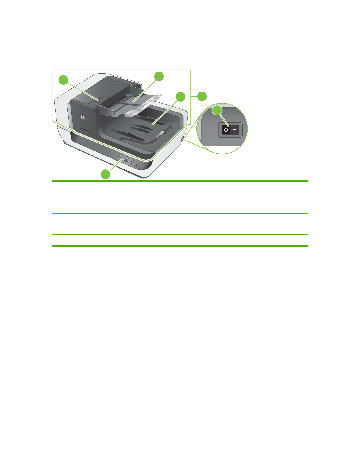
Product walkaround
Front and right-side view
Figure 1-1 Front and right-side view
5
1
1 Front panel
2 ADF
3 ADF input tray
4 ADF output tray
5 Latch for opening the ADF jam door 1
6 Power switch
3
4
2
2
6
4 Chapter 1 Product basics ENWW
Page 27
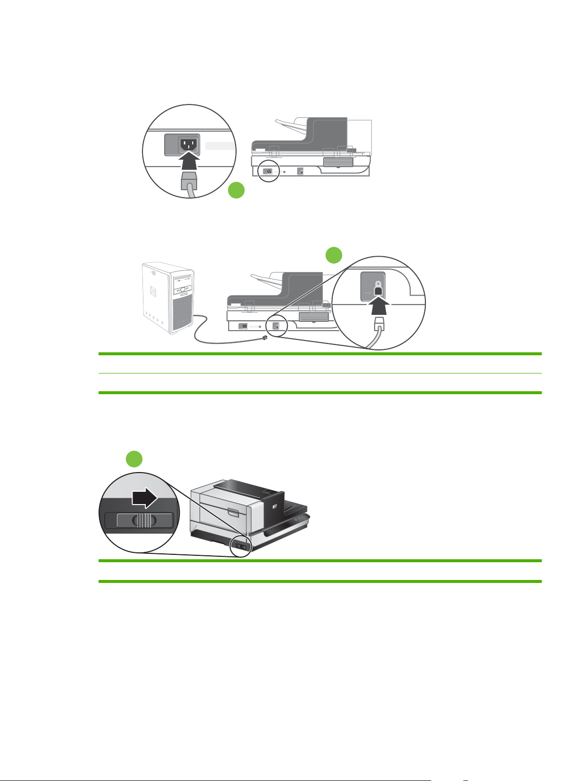
Back view
Figure 1-2 Back view
1
2
1 Power receptacle
2 USB port
Side view (left)
Figure 1-3 Side view (left)
1 Scanner carriage lock
1
ENWW Product basics 5
Page 28

Model and serial numbers
The model and serial numbers are listed on identification labels located on the ADF and flatbed scanner.
Figure 1-4 Model and serial number (1 of 2)
Figure 1-5 Model and serial number (2 of 2)
NOTE: If the product is owned by the U.S. government, the ADF and flatbed scanner have a special
serial-number designation. Replacement components for these products must have a similar serialnumber designation.
6 Chapter 1 Product basics ENWW
Page 29

Control-panel walkaround
Figure 1-6 Control-panel features
1
2
3
Table 1-3 Control-panel features
Item Icon Button name Description
1 Copy By default, print the number of copies currently configured in
2 Scan By default, start a scan that uses the HP Smart Document Scan
4
5
6
HP Document Copy.
Alternatively, start the scanning software that is assigned to this
button.
software profile that is assigned to this button.
Alternatively, start the scanning software that is assigned to this
button.
3 Cancel Cancel a scan or copy in progress.
4 Tools Open the HP Scanner Tools Utility where you can do the following
tasks:
Associate the scanner control-panel buttons with scanning
●
software.
Configure the buttons on the scanner front panel.
●
Manage the imprinter.
●
View information about scanner settings, status, and
●
maintenance.
5 Attention LED The Attention LED provides status information about the scanner.
6 Power Save Press the Power Save button to put the scanner in Power Save
mode when you are not using the scanner. When you are ready
to begin scanning again, press the Power Save button to wake up
the scanner.
ENWW Product basics 7
Page 30

Supported product software
Supported operating systems
The product supports the following operating systems:
Microsoft® Windows 2000
●
Windows® XP Home/Professional
●
Windows Vista®
●
Linux 2.4 and 2.6 Kernel Available
●
Supported scanner drivers
The product supports the following scanner drivers:
Twain
●
ISIS
●
WIA
●
Supported scanner-management software
HP Scanning Software CD
HP Scanner Tools Utility
●
HP Smart Document Scan
●
Kofax VRS Pro
●
Third-party document-management software
●
8 Chapter 1 Product basics ENWW
Page 31

System requirements
The host computer must meet the minimum system hardware requirements to load and utilize the inbox software.
Minimum system hardware requirements:
●
1.4 GHz processor
◦
600 MB free hard disk space
◦
USB 2.0 and higher
◦
CD-ROM drive
◦
1024 x 768 SVGA monitor, 16-bit color
◦
HP recommends that the host computer system hardware meet the following requirements to
●
assure the optimum performance of the scanner at the quoted speed specifications.
Recommended system hardware requirements:
USB 1.1 and higher
◦
CD-ROM drive
◦
1024 x 768 SVGA monitor, 16-bit color
◦
80 MB (drivers only)
◦
300 MB (minimum) free hard disk space
◦
For Microsoft Windows XP Home, Windows XP Professional or Windows 2000:
●
1 GB RAM (recommended)
◦
256 MB RAM (minimum)
◦
500 MHz processor
◦
Internet Explorer 6 and higher
◦
For Windows Vista:
●
1 GB RAM (recommended)
◦
512 MB RAM (minimum)
◦
800 MHz processor
◦
Microsoft Internet Explorer 7 and higher
◦
ENWW System requirements 9
Page 32

Paper handling
ADF specifications
Table 1-4 ADF specifications
Description Specification
Paper-tray capacity
Minimum paper size 70 x 148 mm (2.75 x 5.8 in)
Maximum paper size 300 x 864 mm (11.8 x 34 in)
Minimum paper weight
Minimum paper weight
Media specifications
The ADF supports the following widths, lengths, and weights of paper.
Table 1-5 Media specifications
Description Specification
Width 70–300 mm (2.75–11.8 in)
Length 148–864 mm (5.8–34 in)
Weight
NOTE: The ADF input tray supports up to 200 sheets of 75 g/m2 (20 lb) paper.
49–120 g/m
2
(13–32 lb)
200 sheets of 75 g/m2 (20 lb)
49 g/m2 (13 lb)
2
120 g/m
(32 lb)
10 Chapter 1 Product basics ENWW
Page 33

Media to avoid
Scanning certain types of documents through the ADF might result in jams or damage to the document.
HP recommends scanning these types of documents by using the scanner only:
Wrinkled or creased documents
●
Torn documents
●
Carbon paper
●
Extremely thin, translucent paper
●
Photos
●
Papers that are stuck together
●
Curled documents
●
Documents with paperclips or staples
●
Coated paper
●
Paper with adhesive notes or flags attached
●
Overhead transparencies
●
Paper with wet substances such as glue or correction fluid
●
ENWW Paper handling 11
Page 34

12 Chapter 1 Product basics ENWW
Page 35

2 Installation and configuration
Prepare the site
●
Unpack the device
●
Install the software
●
ENWW 13
Page 36

Prepare the site
The scanner must be installed in a well-ventilated, dust-free area. Place the product on a sturdy, level
surface.
For information about product specifications, see
Specifications on page 359.
CAUTION: To avoid injury, use two people to unpack and lift the scanner.
Verify that there is enough clearance to use and maintain the scanner.
Figure 2-1 Site dimensions
110 mm
4.33 in
350 mm
13.78 in
130 mm
5.12 in
105 mm
4.13 in
14 Chapter 2 Installation and configuration ENWW
Page 37

Unpack the device
1. Unlock the box.
Figure 2-2 Unpack the device (1 of 9)
2. Remove the top of the box.
Figure 2-3 Unpack the device (2 of 9)
ENWW Unpack the device 15
Page 38

3. Remove the top packing material, and then remove all remaining packing material and tape from
the outside of the ADF.
Figure 2-4 Unpack the device (3 of 9)
4. Remove the scanner from the box.
CAUTION: To avoid injury, use two people to lift the device from the box.
Figure 2-5 Unpack the device (4 of 9)
38.5 kg
85 lbs
5. Take an inventory of the contents.
The following items should be included with each HP Scanjet N9120 scanner.
NOTE: The contents might vary by country/region.
16 Chapter 2 Installation and configuration ENWW
Page 39

Figure 2-6 Unpack the device (5 of 9)
4
3
1
Table 2-1 Box contents
Item Description
1 HP Scanjet N9120 scanner
2 Scanning software CDs
3 Power cable
4 USB cable
5 Getting Started Guide
6. Place the product on a sturdy, level surface.
7. Release the carriage lock.
Figure 2-7 Unpack the device (6 of 9)
2
5
8. Remove the spacer tape from ADF jam door 1 and ADF jam door 2.
Figure 2-8 Unpack the device (7 of 9)
ENWW Unpack the device 17
Page 40

9. Open ADF jam door 1, and then remove the spacers.
Figure 2-9 Unpack the device (8 of 9)
10. Open ADF jam door 2, and then remove the spacers.
Figure 2-10 Unpack the device (9 of 9)
11. Remove any remaining packing material, and then close ADF jam door 1 and ADF jam door 2.
18 Chapter 2 Installation and configuration ENWW
Page 41

Install the software
CAUTION: Do not connect the USB cable until you are prompted during the software installation.
1. Decide what software to install.
If you will be using the scanner with document-management and scanning software that you
●
already own, you only need to install the HP Scanjet utilities drivers and tools.
If you do not already have document-management and scanning software, you can use the
●
software that is shipped with the scanner. Read the onscreen descriptions of the software
during the installation to decide what software to install.
2. Insert the HP Scanning Software CD into the computer CD drive. Wait for the installation dialog
box to appear.
3. Click Install Software, and then follow the instructions on the screen.
4. Use the power cable to connect the scanner to an electrical outlet.
Figure 2-11 Electrical connection
5. Use the USB cable that came with the scanner to connect the scanner to the computer.
CAUTION: Be sure that you install the HP scanning software before connecting the scanner to
your computer with the USB cable.
NOTE: HP recommends using a USB port on the back of the computer for a more reliable
connection to the scanner.
Figure 2-12 USB connection
ENWW Install the software 19
Page 42

6. Press the power switch on the right side of the scanner to the on position.
Figure 2-13 Power switch
7. Test the installation. Place a single document page in the ADF, and then do one of the following:
If you installed the HP Smart Document Scan software, press the Scan button.
●
If you did not install the HP Smart Document Scan software, scan from the software that you
●
intend to use for scanning.
If the scan does not proceed as expected, uninstall and reinstall the HP Scanjet utilities, and then
try scanning again. If reinstalling the utilities does not work, see the scanning software
documentation for information on how to troubleshoot that program.
For information on uninstalling and reinstalling the HP Scanjet utilities, see the product user guide.
20 Chapter 2 Installation and configuration ENWW
Page 43

3 Manage and maintain
Manage supplies
●
Clean the product
●
ENWW 21
Page 44

Manage supplies
HP Scanner Tools Utility scanner maintenance information
The Maintenance tab of the HP Scanner Tools Utility displays the scanner usage and maintenance
history. You can use this tab to record scanner maintenance.
The Imprinter tab of the HP Scanner Tools Utility displays information about the scanner imprinter and
the imprinter print cartridge. You can use this tab to record that the print cartridge has been replaced.
To open the HP Scanner Tools Utility, press the Tools button on the scanner front panel.
NOTE: For detailed information on using the HP Scanner Tools Utility, see the HP Scanner Tools
Utility help.
Parts life expectancy
Table 3-1 Replacement guidelines
Item Guideline How to
ADF base reflector The ADF base reflector needs to be
replaced only if it is damaged or if you
see vertical streaks on the scanned
images.
NOTE: Before you replace the white
ADF base reflector, try cleaning the
product. See
on page 23.
Pickup-roller assembly The pickup-roller assembly needs to be
replaced after 100,000 scans.
NOTE: HP recommends that you clean
the pickup roller every 50,000 pages.
See
Clean the product on page 23.
Separation-pad assembly The separation pad needs to be replaced
after 100,000 scans.
Imprinter cartridge Replace the imprinter cartridge when it is
out of ink.
Fan filters The fan filters should be replaced when
a user-replaceable part is installed or
when filters are damaged or worn from
cleaning.
Clean the product
To replace the ADF base reflector, see
ADF base reflector on page 45.
To replace the pickup-roller assembly,
see
Pickup-roller assembly
on page 47.
To replace the separation-pad assembly,
see
Separation-pad assembly
on page 49.
To replace the imprinter cartridge, see
Imprinter cartridge on page 42.
To replace a fan filter, see Fan filters
on page 44.
22 Chapter 3 Manage and maintain ENWW
Page 45

Clean the product
During the scanning process, paper and dust particles can accumulate inside the product. Over time,
this buildup can cause problems, such as specks or streaks on scanned documents.
Occasional cleaning of the product helps ensure high-quality scans. The amount of care necessary
depends upon several factors, including the amount of use and the environment. You should perform
routine cleaning as necessary.
Routine cleaning and maintenance should include cleaning the ADF, the scanner glass, and the fan
filters.
Clean the exterior
Use a soft, damp, lint-free cloth to wipe dust, smudges, and stains off of the exterior of the product.
ENWW Clean the product 23
Page 46

Clean the ADF
NOTE: The customer should be advised to clean the ADF only when scanned documents show
streaks, specks, or other signs of degradation that can be directly attributed to the scanning process.
The ADF requires periodic maintenance depending on the amount of use and the type of paper that is
fed through it. Clean the ADF under the following conditions:
The ADF has trouble feeding documents.
●
Vertical streaks appear in images scanned by the ADF.
●
Scanned documents are dusty, dirty, or have pencil writing (graphite) on them.
●
The environment is dusty.
●
Clean the ADF:
1. Press the power switch to the off position, and then disconnect the USB cable and power cable
from the scanner.
2. Open the ADF.
Figure 3-1 Clean the ADF (1 of 5)
24 Chapter 3 Manage and maintain ENWW
Page 47

3. Clean the clear scanning strip on the scanner bed. Wipe the clear area with a clean, dry, lint-free
cloth.
CAUTION: Use only glass cleaner to clean the scanning strip. Avoid cleaners that contain
abrasives, acetone, benzene, or carbon tetrachloride, all of which can damage the scanner glass.
Avoid isopropyl alcohol because it can leave streaks on the glass.
Do not spray the glass cleaner directly on the glass. If too much glass cleaner is applied, the cleaner
could leak under the glass and damage the scanner.
Figure 3-2 Clean the ADF (2 of 5)
4. Close the ADF.
5. Open jam door 1 (callout 1) and jam door 2.
Figure 3-3 Clean the ADF (3 of 5)
1
ENWW Clean the product 25
Page 48

6. Locate the white strip (callout 1) on jam door 2 and the scan window (callout 2) inside the ADF,
and then wipe both of these areas with a clean, dry, lint-free cloth.
Figure 3-4 Clean the ADF (4 of 5)
2
1
7. Wipe the rollers with a clean, damp, lint-free cloth.
Figure 3-5 Clean the ADF (5 of 5)
8. Wait several minutes for the rollers to dry, and then close jam door 1 and jam door 2.
9. Reconnect the USB cable and power cable to the scanner, and then press the power switch to the
on position.
26 Chapter 3 Manage and maintain ENWW
Page 49

Clean the scanner glass
Clean the scanner glass under the following conditions:
Streaks, scratches, or spots appear in images scanned from the scanner glass.
●
Dusty or dirty documents have been scanned using the glass.
●
The environment is dusty.
●
Clean the scanner glass:
1. Press the power switch to the off position, and then disconnect the USB cable and power cable
from the scanner.
2. Open the ADF.
Figure 3-6 Clean the scanner glass
3. Clean the glass with a soft, lint-free cloth that has been sprayed with a mild glass cleaner.
CAUTION: Use only glass cleaner to clean the scanner glass. Avoid cleaners that contain
abrasives, acetone, benzene, or carbon tetrachloride, all of which can damage the scanner glass.
Avoid isopropyl alcohol because it can leave streaks on the glass.
Do not spray the glass cleaner directly on the glass. If too much glass cleaner is applied, the cleaner
could leak under the glass and damage the scanner.
4. Dry the glass with a dry, soft, lint-free cloth.
5. Reconnect the USB cable and power cable to the scanner, and then press the power switch to the
on position.
ENWW Clean the product 27
Page 50

Clean the fan filters
The flatbed scanner includes two fan filters. These filters prevent dust and debris from entering the fans.
If the scanner is in a dirty or dusty environment, clean the filters monthly.
NOTE: The ADF filter cover is not removable.
1. Press the power switch to the off position, and then disconnect the USB cable and power cable
from the scanner.
2. Remove the filter cover.
Figure 3-7 Clean the scanner fan filters (1 of 2)
3. Clean the filter in one of the following ways:
Use compressed air to blow the debris off of the filter.
●
Use a vacuum to remove the debris from the filter.
●
Rinse the filter with water.
●
4. Inspect the filter cover. If it is dirty, use a clean, damp, lint-free cloth to remove the dirt.
5. Make sure that the filter and the filter cover are completely dry.
CAUTION: The filter must be completely dry before you reinstall it in the product and turn the
power on. If the filter is damp, the fan could pull moisture into the product and cause damage to
the product.
6. Place the clean, dry filter in the filter cover, and then replace the cover on the scanner.
Figure 3-8 Clean the scanner fan filters (2 of 2)
7. Reconnect the USB cable and power cable to the scanner, and then press the power switch to the
on position.
28 Chapter 3 Manage and maintain ENWW
Page 51

4 Theory of operation
Basic operation
●
Modes and control-panel indicators
●
Circuit board assemblies
●
Fans
●
ADF feed system
●
Service block diagram
●
ENWW 29
Page 52

Basic operation
The Scanjet N9120 consists of two main assemblies.
Table 4-1 Main assemblies
Name Description
ADF
Flatbed scanner
ADF motor control circuitry
●
Media transport mechanism
●
Ultrasonic multi-pick detection
●
Imprinter
●
Optical assembly
●
Scanner control circuitry
●
System power supply
●
Control panel
●
Optical assembly
●
30 Chapter 4 Theory of operation ENWW
Page 53

Modes and control-panel indicators
Table 4-2 Modes and control-panel indicators
Mode Description
Power on The period of time from when the power switch is turned on until the green LED illuminates the sleep button
on the control panel.
Initialization/
Warm-up
Scan The period of time immediately following the request for a scan, from either the ADF or the scanner. This
Sleep This mode starts in either of the following ways: The user presses the sleep button on the control panel, or
Error The period of time in which the scanner is unable to complete the task it was directed to perform. This can
Maintenance
event
The period of time after the power-on sequence or sleep mode wake-up event and before the scanner is
ready to scan. During this time, the scanner and ADF initialization sequences are completed, the Cold
Cathode Fluorescent Lamps (CCFL) are turned on and complete their warm up cycle, scanner and ADF
calibration are completed, ADF motors are enabled, and sensor states are verified to ensure that no media
is in the media transport path. This period of time is indicated by a slowly blinking green attention LED on
the control panel.
period of time is indicated by a quickly blinking green attention LED on the control panel.
the scanner is not used for 15 minutes or longer. This period of time is indicated by an amber LED
illumination of the sleep button on the control panel.
be the result of a paper jam, communication error with the PC, or similar event. This period of time is
indicated by a blinking amber attention LED illumination on the control panel.
This mode is indicated by a solid amber attention LED illumination on the control panel and starts when a
maintenance event is triggered (such as the need for separation pad replacement). Maintenance events
occur during predefined intervals to help ensure that the scanner or ADF mechanisms continue to perform
as specified.
ENWW Modes and control-panel indicators 31
Page 54

Circuit board assemblies
Table 4-3 Circuit board assemblies
Location Name Description
ADF ADF controller
board
CCD board Composed of CCD, AFE, and various discrete devices. Located on the ADF optical
Lamp inverter
board
Ultrasonic sensor
transmitter board
Ultrasonic sensor
receiver board
Imprinter board This board consists of the power transistors that are used to control the firing of the
Flatbed scanner Scanner control
board
This board controls all of the ADF motor operation, including the background color
solenoid, and sensor detection within the ADF mechanism. Additionally, it controls
the firing timing of the imprinter ink cartridge. This board is composed of a Gate Array,
an Analog to Digital Converter, and various motor control devices. It is located in the
ADF assembly.
carriage assembly. This board is not serviceable.
Used to control the CCFL lamps and heater wires. Located on the bottom of the ADF
optical carriage assemblies. This board is not serviceable.
Transmits the ultrasonic signal to the receiver on the other side of the media
transportation path of the ADF assembly. Located on the bottom of the media
transportation path in the ADF assembly.
Receives the ultrasonic signal from the transmitter on the other side of the media
transportation path in the ADF assembly. Located on the top side of the media
transportation path in the ADF assembly.
12 ink nozzles on the imprinter ink cartridge. It is located in the ADF assembly.
This is the main board in the entire system, which is composed of the main control
and image pipe ASIC, the JPEG compression chip, SRAM, SDRAM, Flash RAM,
DDR2 Memory, FPGA (for sensor data reordering), LVDS receivers, DC/DC
converters, etc. This board controls Analog Front End (AFE) and CCD timing and
receives and processes the information from both of the optical heads in the scan
system, performs all requested operations from the user, and transfers the output
image data through the high speed USB interface to the attached Host PC. Located
in the scanner assembly.
Power supply Supplies 5V and 24V outputs for all system operation. Located in the scanner
Relay board Cabling interface board between the scanner control board and the CCD board.
CCD board Composed of CCD, AFE, and various discrete devices. Located on the optical
Lamp inverter
board
Control panel board Communicates to the scanner control board through the microcontroller USB 1.1
assembly.
Located on the scanner optical assembly and the control panel circuit board. This
board is not serviceable.
carriage assembly. This board is not serviceable.
Used to control the CCFL lamps and heater wires. Located on the bottom of the optical
carriage assemblies. This board is not serviceable.
interface, which passes through the relay board. This board consists of a
microcontroller, Flash RAM, switches, and LEDs. Located on the front of the scanner
assembly.
32 Chapter 4 Theory of operation ENWW
Page 55

Fans
The Scanjet N9120 system has four fans, each of which have failure detection algorithms included in
the system firmware:
ADF motor fan. See
●
ADF carriage fan. See
●
Scanner carriage-motor fan. See
●
Scanner carriage fan. See
●
ADF motor fan on page 101.
ADF carriage fan on page 102.
Scanner carriage-motor fan on page 203.
Scanner carriage fan on page 206.
ENWW Fans 33
Page 56

ADF feed system
Sensors
Figure 4-1 Sensors
4
7
11
8
9
10
12
13
5
6
3
16
2
1
14
15
17
18
Table 4-4 Sensors
Item Description
1 Input-tray sensor (open). See Input-tray sensor on page 129.
2 Paper-present sensor. See Paper-present sensor on page 139.
3 Elevator arm sensor. See Elevator arm sensor on page 137.
4 Pick-up roller sensor. See Pick-up roller sensor on page 135.
5 Jam door 1 sensor. See Jam door 1 sensor on page 141.
6 Registration sensor. See Registration sensor on page 140.
7 Upper multi-pick sensor PCA. See Upper multi-pick sensor PCA on page 119.
8 Lower multi-pick sensor PCA. See Lower multi-pick sensor PCA on page 121.
9 Jam door 2 sensor. See Jam door 2 sensor on page 142.
10 ADF scan position sensor. See ADF scan position sensor on page 146.
11 Background solenoid sensor. See Background solenoid sensor on page 138.
12 Flatbed scan position sensor. See Flatbed scan position sensor on page 130.
13 Exit 1 sensor. See Exit 1 sensor on page 133.
14 Jam door 3 sensor. See Jam door 3 sensor on page 143.
15 Imprinter paper-present sensor. See Imprinter paper-present sensor on page 144.
16 Exit 2 sensor. See Exit 2 sensor on page 134.
17 ADF open sensor (not serviceable).
18 Carriage home position sensor (not serviceable).
34 Chapter 4 Theory of operation ENWW
Page 57

Motors
Figure 4-2 Motors
2
3
4
1
5
Item Description
1 Driven by ADF input-tray lift-motor assembly. See ADF input-tray lift-motor assembly on page 103.
2 Driven by ADF pick-motor assembly. See ADF pick-motor assembly on page 114.
3 Driven by ADF feed-motor assembly. See ADF feed-motor assembly on page 108.
4 ADF background-solenoid assembly. See ADF background-solenoid assembly on page 194.
5 Driven by ADF exit-motor assembly. See ADF exit-motor assembly on page 104.
ENWW ADF feed system 35
Page 58

Service block diagram
Figure 4-3 Service block diagram
Flatbed Carriage Assembly
FL La
CC
/ Heate
oard
Even
Pixe
oard
Scanner Control Board
mps (2)
r Wire
ls
FPGA
AS
IC
ntrol Pane
Co
Lamp Inverter
Board
CC
D B
Odd
l
ls
Board
Pixe
y B
Rela
LVDS Receiver LVDS Receiver LVDS ReceiverLVDS Receiver
USB Host 1.1 FS I/F USB Device 2.0 HS I/F
CCFL Lamps (2)
/ Heater Wire
Odd
Pixels
ADF Carriage Assembly
Lamp Invert
Board
D Boar
CC
d
Even
Pixels
er
Imprinter
Driver
Bo
ard
nsors:
ADF Se
·Input Tray
·P
·Elevat
·Pick up Roller
·Jam D
·Registration
·
·Lower Mult
· Jam Door 2
·A
· Background Solenoid
· FB Scan Position
·Exit 1
·Jam D
· Imprinter Paper Present
·Exit 2
Transm
aper Present
Upper Multi-pick
DF S
Ultrasonic
itt
ard
Bo
AD
F Cont
Ope
r
Arm
o
oor 1
i-pic
can Position
oor 3
er
rol Board
n
k
Ultrasonic
R
eceiv
Board
Automatic
Document
Feeder
(ADF)
AD
F
lev
Input E
ator
or
Mot
ADF
ick/Sep
P
Motor
AD
er
F
Feed Motor
ADF
Exit Motor
Background
Solenoid
ADF
Carriage Fan
ADF
Motor Fan
Scanner
Carriage Fan
Scanner
Motor F
an
Scanner
r
Moto
Scanner Sensors:
·ADF Open
arri
·C
age Home Position
Flatbed
Carriage Motor
Flatbed
Scanner
Power Supp
ard
Bo
Personal
ly
Computer
36 Chapter 4 Theory of operation ENWW
Page 59

5 Removal and replacement
Removal and replacement strategy
●
User-replaceable parts
●
External covers
●
Automatic document feeder FRUs
●
Flatbed scanner FRUs
●
ENWW 37
Page 60

Removal and replacement strategy
This chapter discusses the removal and replacement of field-replaceable units (FRUs) only.
Replacing FRUs is generally the reverse of removal. Occasionally, notes and tips are included to provide
directions for difficult or critical replacement procedures.
HP does not support repairing individual subassemblies or problem solving at the component level.
Note the length, diameter, color, type, and location of each screw. Be sure to return each screw to its
original location during reassembly.
Incorrectly routed or loose wire harnesses can interfere with other internal components and can become
damaged or broken. Frayed or pinched harness wires can be difficult to locate. When replacing wire
harnesses, always use the provided wire loops, lance points, or wire-harness guides.
General cautions during removal and replacement
WARNING! Turn the product off, wait 5 seconds, and then remove the power cord before attempting
to service the product. If this warning is not followed, severe injury can result, as well as damage to the
product. The power must be on for certain functional checks during problem solving. However, the power
supply should be disconnected during parts removal.
The sheet-metal parts can have sharp edges. Be careful when handling sheet-metal parts.
CAUTION: Do not bend or fold the flat flexible cables (FFCs) during removal or installation. Also, do
not straighten folds in the FFCs. You must make sure that all FFCs are fully seated in their connectors.
Failure to fully seat an FFC into a connector can cause a short circuit in a PCA.
Avoid pulling directly on wires to disconnect wire-harness connectors. Pull on the plastic body of a
connector if possible to avoid damaging the connector wires.
NOTE: To install a self-tapping screw, first turn it counterclockwise to align it with the existing thread
pattern, and then carefully turn it clockwise to tighten. Do not overtighten. If a screw hole becomes
stripped, repair the screw hole or replace the affected assembly.
Electrostatic discharge
CAUTION: Some parts are sensitive to electrostatic discharge (ESD). Look for the ESD reminder
when removing product parts. Always perform service work at an ESD-protected workstation or mat. If
an ESD workstation or mat is not available, ground yourself by touching the sheet-metal chassis
before touching an ESD-sensitive part.
Protect the ESD-sensitive parts by placing them in ESD pouches when they are out of the product.
38 Chapter 5 Removal and replacement ENWW
Page 61

Required tools
#2 Phillips screwdriver with a magnetic tip and a 152 mm (6.0 inch) shaft length
●
Short #2 Phillips screwdriver with a magnetic tip and a 76 mm (3.0 inch) shaft length
●
Small flat-blade screwdriver
●
Needle-nose pliers
●
ESD mat (if available; see the preceding ESD caution)
●
Penlight (optional)
●
CAUTION: Always use a Phillips screwdriver (callout 1). Do not use a pozidrive screwdriver (callout 2)
or any motorized screwdriver. These can damage screws or screw threads.
Figure 5-1 Phillips and pozidrive screwdriver comparison
Cleaning supplies
The scanner glass and ADF must be cleaned with appropriate supplies.
When cleaning the scanner glass, see
When cleaning the ADF, see
Screws and fasteners
Make sure that components are replaced with the correct screw type. Using the incorrect screw (for
example, substituting a long screw for the correct shorter screw) can cause damage to the product or
interfere with product operation. Do not intermix screws that are removed from one component with the
screws that are removed from another component.
For a complete list of screws and fasteners, see
Before performing service
1. Turn off the power by using the power switch.
2. Unplug the power cable and interface cable(s).
3. Remove all media from the product.
4. Place the product on an ESD mat (if one is available). If an ESD workstation or mat is not available,
ground yourself by touching the sheet-metal chassis before touching an ESD-sensitive part.
Clean the scanner glass on page 27.
Clean the ADF on page 24.
Field replaceable units (FRUs) on page 287.
5. Remove the imprinter cartridge. See
ENWW Removal and replacement strategy 39
Imprinter cartridge on page 42.
Page 62

After performing service
1. Clean the outside of the product with a damp cloth.
2. If the ADF had an imprinter cartridge installed, reinstall it. See
3. Replace media in the ADF input tray.
4. Plug in the power cable and interface cable(s).
5. Turn on the power by using the power switch, and then verify that the expected startup sounds
occur.
6. Verify host computer and scanner connectivity.
7. Verify that the most recent firmware is installed by using the Scanner Tools Utility.
8. Verify NVRAM data and make changes as required.
9. Perform scan-quality tests:
a. Perform a scan job from the ADF, and then verify that the output meets expectations.
b. Perform a scan job from the glass, and then verify that the output meets expectations.
c. Send a scan job from the host computer, and then verify that the output meets expectations.
10. If the imprinter cartridge was reinstalled, open the HP Scanner Tools Utility, click the Imprinter tab,
and then click Test imprinter.
Imprinter cartridge on page 42.
40 Chapter 5 Removal and replacement ENWW
Page 63

User-replaceable parts
Imprinter cartridge
●
Fan filters
●
ADF base reflector
●
Pickup-roller assembly
●
Separation-pad assembly
●
ENWW User-replaceable parts 41
Page 64

Imprinter cartridge
1. Raise the ADF input tray until it clicks into place.
Figure 5-2 Remove the imprinter cartridge (1 of 4)
2. Lift the green lever on the imprinter carriage to disengage it from the page-size slot, and then slide
the imprinter carriage completely to the left.
Figure 5-3 Remove the imprinter cartridge (2 of 4)
42 Chapter 5 Removal and replacement ENWW
Page 65

3. Raise the imprinter-cartridge latch.
Figure 5-4 Remove the imprinter cartridge (3 of 4)
4. Slide the cartridge to the right, and then remove it from the imprinter carriage.
Figure 5-5 Remove the imprinter cartridge (4 of 4)
ENWW User-replaceable parts 43
Page 66

Fan filters
NOTE: Fan filters are located behind the back-filter cover (shown in this procedure) and the right-filter
cover. The back-upper cover does not contain a filter. Use this procedure to remove either of the fanfilter covers or fan filters.
1. Remove the fan-filter cover.
Figure 5-6 Remove the fan filter (1 of 2)
2. Rotate the fan-filter cover away from the product, and then remove the fan filter.
Figure 5-7 Remove the fan filter (2 of 2)
44 Chapter 5 Removal and replacement ENWW
Page 67

ADF base reflector
1. Open the ADF.
Figure 5-8 Remove the ADF base reflector (1 of 2)
2. Pull the ADF base reflector from the bottom of the ADF.
Figure 5-9 Remove the ADF base reflector (2 of 2)
ENWW User-replaceable parts 45
Page 68

Reinstall the ADF base reflector
Place the ADF base reflector on the scanner glass with the white adhesive squares facing up and the
tab-like cutout toward the front, and then close the ADF.
Figure 5-10 Reinstall the ADF base reflector
46 Chapter 5 Removal and replacement ENWW
Page 69

Pickup-roller assembly
1. Remove the pickup-roller cover. See Pickup-roller cover on page 183.
2. Pull the roller end of the shaft away from the product to disengage it (callout 1), slide the assembly
toward the front of the product to release the drive-gear end of the shaft (callout 2), and then remove
the pickup-roller assembly (callout 3).
Figure 5-11 Remove the pickup-roller assembly
2
1
3
ENWW User-replaceable parts 47
Page 70

Reinstall the pickup-roller assembly
1. When you reinstall the pickup-roller assembly, make sure that the spring is correctly positioned
between the pickup-roller assembly and the ADF jam door 1.
NOTE: Replace the pickup-roller spring if it is bent or damaged. See Pick-up roller spring
on page 175.
Figure 5-12 Reinstall the pickup-roller assembly (1 of 2)
2. Install the drive-gear end of the shaft (callout 1) into the retainer, and then slide the assembly toward
the back of the product.
a. Push the roller end of the shaft into the retainer (callout 2).
b. Rotate the assembly into place (callout 3).
Figure 5-13 Reinstall the pickup-roller assembly (2 of 2)
1
3
2
3. Replace the pickup-roller cover.
48 Chapter 5 Removal and replacement ENWW
Page 71

Separation-pad assembly
1. Release one tab.
Figure 5-14 Remove the separation-pad assembly (1 of 3)
2. Slide the separation-pad assembly to the right (callout 1), and then rotate the separation-pad
assembly toward the front of the product to release the left-side hinge pin (callout 2).
Figure 5-15 Remove the separation-pad assembly (2 of 3)
2
1
ENWW User-replaceable parts 49
Page 72

3. Remove the separation-pad assembly.
Figure 5-16 Remove the separation-pad assembly (3 of 3)
Reinstall the separation-pad assembly
When reinstalling the separation-pad assembly, make sure that the spring is correctly positioned under
the assembly.
NOTE: Replace the separation-pad spring if it is bent or damaged. See Separation-pad spring
on page 176.
Figure 5-17 Reinstall the separation-pad assembly
50 Chapter 5 Removal and replacement ENWW
Page 73

External covers
Scanner control-panel cover
●
Scanner back-filter cover
●
Scanner right-filter cover
●
ADF front cover
●
ADF back cover
●
Scanner back cover
●
ENWW External covers 51
Page 74

Scanner control-panel cover
Release five tabs, and then rotate the front scanner control-panel cover away from the product to remove
it.
Figure 5-18 Remove the scanner control-panel cover
52 Chapter 5 Removal and replacement ENWW
Page 75

Scanner back-filter cover
Remove the scanner back-filter cover. See Fan filters on page 44.
Scanner right-filter cover
Remove the scanner right-filter cover. See Fan filters on page 44.
ENWW External covers 53
Page 76

ADF front cover
1. Open the ADF.
2. Remove three screws (callout 1).
Figure 5-19 Remove the ADF front cover (1 of 5)
1
3. Remove two screws (callout 2).
Figure 5-20 Remove the ADF front cover (2 of 5)
2
54 Chapter 5 Removal and replacement ENWW
Page 77

4. Rotate the top of the ADF front cover away from the ADF.
NOTE: Pull cover away from the ADF to create a small space between the cover and ADF.
Figure 5-21 Remove the ADF front cover (3 of 5)
5. Release three tabs (callout 3).
Figure 5-22 Remove the ADF front cover (4 of 5)
3
ENWW External covers 55
Page 78

6. Remove the ADF front cover.
Figure 5-23 Remove the ADF front cover (5 of 5)
56 Chapter 5 Removal and replacement ENWW
Page 79

ADF back cover
1. Open the ADF jam door 1.
2. Remove two screws (callout 1).
Figure 5-24 Remove the ADF back cover (1 of 3)
1
3. Remove two screws and two tabs (callout 2).
Figure 5-25 Remove the ADF back cover (2 of 3)
2
ENWW External covers 57
Page 80

4. Rotate the top of the cover away from the product to release it, and then remove the cover.
Figure 5-26 Remove the ADF back cover (3 of 3)
58 Chapter 5 Removal and replacement ENWW
Page 81

Scanner back cover
1. Remove two screws (callout 1).
Figure 5-27 Remove the scanner back cover (1 of 2)
2. Firmly pull the cover away from the product to remove it.
11
Figure 5-28 Remove the scanner back cover (2 of 2)
ENWW External covers 59
Page 82

Automatic document feeder FRUs
Automatic document feeder (ADF)
●
ADF motor fan
●
ADF carriage fan
●
ADF input-tray lift-motor assembly
●
ADF exit-motor assembly
●
ADF feed-motor assembly
●
ADF pick-motor assembly
●
Upper multi-pick sensor PCA
●
Lower multi-pick sensor PCA
●
ADF controller PCA
●
Imprinter PCA
●
Input-tray sensor
●
Flatbed scan position sensor
●
Exit 1 sensor
●
Exit 2 sensor
●
Pick-up roller sensor
●
Elevator arm sensor
●
Background solenoid sensor
●
Paper-present sensor
●
Registration sensor
●
Jam door 1 sensor
●
Jam door 2 sensor
●
Jam door 3 sensor
●
Imprinter paper-present sensor
●
ADF scan position sensor
●
ADF bottom corner outer paper path guide
●
ADF bottom corner inner paper path guide
●
ADF cal-strip assembly
●
ADF exit inner paper path guide
●
ADF top corner inner paper path guide
●
60 Chapter 5 Removal and replacement ENWW
Page 83

Lower multi-pick sensor cover
●
Flatbed scan position sensor arm
●
Exit 1 sensor arm
●
Exit 2 sensor arm
●
Paper-present-sensor arm
●
Input-tray-elevator arm
●
Registration sensor arm
●
Scan position sensor arm
●
Pick-up roller spring
●
Separation-pad spring
●
ADF input-tray assembly
●
ADF output tray
●
Pickup-roller cover
●
ADF hinge limiters
●
ADF jam door 3
●
Paper present sensor and imprinter PCA holder
●
ADF shingle wall
●
A4 paper-stop
●
ADF background-solenoid assembly
●
Imprinter carriage and FFC
●
ENWW Automatic document feeder FRUs 61
Page 84

Automatic document feeder (ADF)
NOTE: Factory NVRAM data should be downloaded before the service call.
1. Remove the following components:
ADF back cover. See
●
Scanner back cover. See
●
ADF hinge limiters. See
●
2. Remove two connectors (callout 1).
Figure 5-29 Remove the ADF (1 of 8)
ADF back cover on page 57.
Scanner back cover on page 59.
ADF hinge limiters on page 185.
1
3. Remove two FFC connectors, and then feed two FFCs through the wire guide.
Figure 5-30 Remove the ADF (2 of 8)
62 Chapter 5 Removal and replacement ENWW
Page 85

4. Remove one screw (callout 2).
TIP: Place the loose ends of the two FFC connectors into the sleeve on the ADF to prevent them
from being damaged when the ADF is removed.
Figure 5-31 Remove the ADF (3 of 8)
2
5. Remove the wire guide, and then place the two connectors under the power-feed cable in the
scanner chassis (callout 3).
Figure 5-32 Remove the ADF (4 of 8)
3
ENWW Automatic document feeder FRUs 63
Page 86

6. Open the ADF, and then remove two screws (callout 4).
WARNING! The ADF is not restrained when opened and the hinge limiters are removed. The
product can tip over if the ADF is opened too far.
Figure 5-33 Remove the ADF (5 of 8)
4
7. Close the ADF, and then remove two screws (callout 5).
Figure 5-34 Remove the ADF (6 of 8)
5
64 Chapter 5 Removal and replacement ENWW
Page 87

8. Remove two screws (callout 6).
Figure 5-35 Remove the ADF (7 of 8)
6
9. Slide the ADF toward the rear of the product to disengage the locator pins (callout 7), and then lift
up on the ADF to remove it.
Figure 5-36 Remove the ADF (8 of 8)
7
ENWW Automatic document feeder FRUs 65
Page 88

Reinstall the ADF
NOTE: Factory NVRAM data should be downloaded before the service call.
1. Place the ADF on the flatbed scanner, and then slide the ADF toward the front of the product to
engage the locator pins (callout 1).
Figure 5-37 Reinstall the ADF (1 of 7)
1
2. Close the ADF, and then install, but do not tighten, two screws (callout 2).
Figure 5-38 Reinstall the ADF (2 of 7)
2
66 Chapter 5 Removal and replacement ENWW
Page 89

3. Install, but do not tighten, two screws (callout 3).
Figure 5-39 Reinstall the ADF (3 of 7)
3
4. Remove two screws (callout 4).
Figure 5-40 Reinstall the ADF (4 of 7)
4
ENWW Automatic document feeder FRUs 67
Page 90

5. Install and hand tighten two alignment pins (callout 5).
Figure 5-41 Reinstall the ADF (5 of 7)
5
6. Carefully close the ADF and adjust it as necessary so that the alignment pins fit into the holes in
the ADF chassis.
CAUTION: Make sure that the ADF closes completely and is in full contact with the flatbed
scanner.
Figure 5-42 Reinstall the ADF (6 of 7)
68 Chapter 5 Removal and replacement ENWW
Page 91

7. Carefully open the ADF, and then Install, but do not fully tighten, two screws (callout 6).
WARNING! The ADF is not restrained when opened and the hinge limiters are removed. The
product can tip over if the ADF is opened too far.
Figure 5-43 Reinstall the ADF (7 of 7)
6
8. Close the ADF and verify that it is correctly positioned on the alignment pins and the flatbed
scanner. Adjust if necessary. See
9. With the ADF in the closed position, fully tighten the four screws at the back of the product. See
Figure 5-38 Reinstall the ADF (2 of 7) on page 66 and Figure 5-39 Reinstall the ADF (3 of 7)
on page 67.
10. Open the ADF, and then fully tighten the remaining two screws. See
(7 of 7) on page 69.
WARNING! The ADF is not restrained when opened and the hinge limiters are removed. The
product can tip over if the ADF is opened too far.
11. Reinstall the wire guide, reconnect the FFCs and wire-harness connectors, and then reinstall the
hinge limiters.
12. Replace the scanner back cover. See
13. Adjust the height of the ADF. See
14. Adjust the NVRAM data. See
15. Align the ADF. See
16. Create the factory calibration data for ADF-A. See
on page 99.
Align the ADF on page 96.
Figure 5-42 Reinstall the ADF (6 of 7) on page 68.
Figure 5-43 Reinstall the ADF
Scanner back cover on page 59.
ADF height adjustment on page 70.
NVRAM data management on page 73.
Create the factory calibration data for ADF-A
ENWW Automatic document feeder FRUs 69
Page 92

ADF height adjustment
NOTE: Factory NVRAM data should be downloaded before the service call.
1. Remove the ADF back cover. See ADF back cover on page 57.
2. Fold the paper template (use 20# paper).
Figure 5-44 ADF height adjustment (1 of 6)
3. Open the ADF, place the folded shim between the ADF and flatbed scanner, with the back edge
of the shim aligned with the back edge of jam door 2, and then close the ADF.
Figure 5-45 ADF height adjustment (2 of 6)
4. Slide the shim approximately 3.0 mm in and out of the product.
NOTE: The ADF should create a slight amount of resistance on the shim as it moves between
the ADF and flatbed scanner.
Figure 5-46 ADF height adjustment (3 of 6)
70 Chapter 5 Removal and replacement ENWW
Page 93

5. Open the ADF, place the folded shim between the ADF and flatbed scanner with the left edge of
the shim aligned with the front edge of jam door 2, and then close the ADF.
Figure 5-47 ADF height adjustment (4 of 6)
6. Slide the shim approximately 3.0 mm in and out of the product.
NOTE: The ADF should create a slight amount of resistance on the shim as it moves between
the ADF and flatbed scanner.
Figure 5-48 ADF height adjustment (5 of 6)
ENWW Automatic document feeder FRUs 71
Page 94

7. Turn the ADF height adjustment screw counterclockwise (callout 1) to adjust the height of the back
edge or clockwise (callout 2) to adjust the height of the front edge of the ADF.
NOTE: Do not adjust the screw on the right-side hinge.
Figure 5-49 ADF height adjustment (6 of 6)
1 2
8. Replace the ADF back cover. See ADF back cover on page 57.
72 Chapter 5 Removal and replacement ENWW
Page 95

NVRAM data management
After replacing the ADF, ADF controller PCA, flatbed, or scanner controller PCA in the field, NVRAM
data between the scanner controller PCA and the ADF controller PCA must be manipulated. The N9120
Service Tool provides tools to manage NVRAM Data, adjust the ADF alignment, and calibrate the
calibration strip of a replacement ADF to an existing scanner controller PCA.
NOTE: Factory NVRAM data should be downloaded before the service call.
Repair menu
The following shows the selections available from the Repair menu:
Figure 5-50 Repair menu (1 of 11)
ENWW Automatic document feeder FRUs 73
Page 96

Repair menu options
The following provides descriptions and options available from the Repair menu:
Figure 5-51 Repair menu (2 of 11)
74 Chapter 5 Removal and replacement ENWW
Page 97

Replacement scenarios
The following seven scenarios provide data selection recommendations for ADF, flatbed scanner,
whole-unit, and controller PCA replacement scenarios:
Scenario #1: Whole ADF replacement
Scenario #1 applies when replacing the whole ADF and NVRAM data is accessible.
Figure 5-52 Replacement scenario #1 (3 of 11)
ENWW Automatic document feeder FRUs 75
Page 98

Scenario #2: ADF controller PCA replacement
Scenario #2 applies when replacing the ADF controller PCA and NVRAM data is accessible.
Figure 5-53 Replacement scenario #2 (4 of 11)
76 Chapter 5 Removal and replacement ENWW
Page 99

Scenario #3: ADF controller PCA replacement
Scenario #3 applies when replacing the ADF controller PCA and NVRAM data is not accessible.
Figure 5-54 Replacement scenario #3 (5 of 11)
ENWW Automatic document feeder FRUs 77
Page 100

Scenario #4: Whole flatbed scanner replacement
Scenario #4 applies when replacing the whole flatbed scanner and NVRAM data is accessible.
Figure 5-55 Replacement scenario #4 (6 of 7)
78 Chapter 5 Removal and replacement ENWW
 Loading...