

Page 1

Notice
The information contained in this document is subject to change
without notice.
Hewlett-Packard makes no warranty of any kind with
regard to this material, including, but not limited to, the
implied warranties of merchantability and fitness for a
particular purpose. Hewlett-Packard shall not be liable for
errors contained herein or for incidental or consequential
damages in connection with the furnishing, performance, or use
of this material.
Hewlett-Packard assumes no responsibility for the use or
reliability of its software on equipment that is not furnished by
Hewlett-Packard.
This document contains proprietary information that is protected
by copyright.All rights are reserved. No part of this document
may be photocopied, reproduced, or translated to another
language without the prior written consent of Hewlett-Packard
Company.
Hewlett-Packard Company
Network Server Division
P.O. Box 58059, Technical Marketing
Santa Clara, CA 95052-8059 USA
© Copyright 1998, Hewlett-Packard Company
LH 3r
Installation
Road Map
HP NetServer
Installation Overview
,
,
,
Configure ISAnon-Plug-and-Play board (if installed)
Select Network Operating System (NOS)
Configure Integrated Remote Assistant
,
,
,
,
,
,
,
Verify contents
Obtain HP Navigator CD-ROM release history
View the Readme File
Test the system hardware using Diagnostic Assistant (optional)
Install Memory and Accessory Boards
Install the NetServer in a rack
Install Additional Mass Storage
First: Install Hardware Using this Road Map
Second: Configure Hardware
,
,
Refer to the
Install HPTopTools
HP NetServer Remote Administrator Guide
Fourth: Install Server Management Software
Third: Install NOS
,
,
For certain versions of Novell NetWare and MS Windows NT, you may use the
HP automated installation process
For NOSs using a vendor-installation process, first create a NOS drivers
diskette, and view and print HP NOS Installation Instructions
5967-4229
Printed on recycled paper.
Printed in June 1998
All manuals and user guides at all-guides.com
all-guides.com
Page 2
Audience Assumptions
This road map is intended for the person who installs, administers,
and troubleshoots LAN servers. Hewlett-Packard Company assumes
that you are qualified in the servicing of computer equipment and
trained in recognizing hazards in products with hazardous energy
levels.
ESD Warning
Tools Required
This HP NetServer contains sensitive electronic devices that can be
damaged by electrostatic discharge (ESD). ESD hazards are a result
of installation or service personnel failing to ground themselves
properly. To be properly grounded, use a proper ESD wrist strap and
work surface grounded to the HP NetServer chassis.
Installation of some accessories require aT15 TORX or a 1/4-inch
flat blade screwdriver, depending on the accessory.
®
1. Verify Contents
2. Obtain Novell IntranetWare Key (Optional)
3. Overview of NetServer Features
4. Obtain HP Navigator CD-ROM Release History
5. Removing and Replacing the Covers
6. InstallAdditional Memory
7. InstallAll Accessory Boards
8. Replace Covers and Cables
9. Install the NetServer in the Rack
10. InstallAdditional Mass Storage Devices
11. Make External Connections
12. Configure the HP NetServer
NetServer LH 3r Installation Road Map
Table of Contents
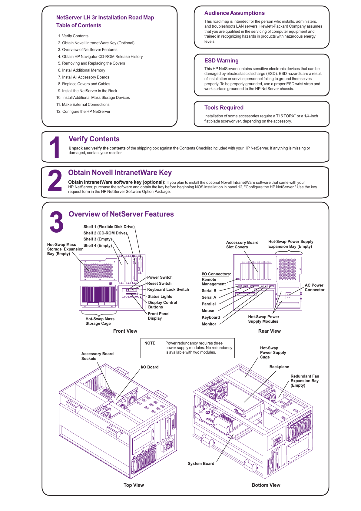
Overview of NetServer Features
Serial B
Serial A
Parallel
Mouse
Keyboard
Monitor
AC Power
Connector
Front View Rear View
Top View
Shelf 1 (Flexible Disk Drive)
Shelf 2 (CD-ROM Drive)
System Board
Backplane
Hot-Swap
Power Supply
Cage
1
2
Shelf 3 (Empty)
Shelf 4 (Empty)
Hot-Swap Mass
Storage Cage
Hot-Swap Power
Supply Modules
Bottom View
Keyboard Lock Switch
Power Switch
Reset Switch
3
Unpack and verify the contents of the shipping box against the Contents Checklist included with your HP NetServer. If anything is missing or
damaged, contact your reseller.
Obtain IntranetWare software key (optional): If you plan to install the optional Novell IntranetWare software that came with your
HP NetServer, purchase the software and obtain the key before beginning NOS installation in panel 12, "Configure the HP NetServer." Use the key
request form in the HP NetServer Software Option Package.
Verify Contents
Obtain Novell IntranetWare Key
Hot-Swap Mass
Storage Expansion
Bay (Empty)
Hot-Swap Power Supply
Expansion Bay (Empty)
Status Lights
Display Control
Buttons
Front Panel
Display
Remote
Management
I/O Connectors:
Accessory Board
Slot Covers
I/O Board
Accessory Board
Sockets
NOTE Power redundancy requires three
power supply modules. No redundancy
is available with two modules.
Redundant Fan
Expansion Bay
(Empty)
All manuals and user guides at all-guides.com
Page 3

4. Reinstall the system board:
5. Replace the cover(s):
Insert the system board into
the plastic guides in the chassis. Extend the retaining latches
while lowering the board until it touches its socket on the
backplane. Close the retaining latches until the system board is
seated firmly in its slot. Connect all I/O cables to the rear of the
system board.
If you are not installing any other
accessories, replace the cover(s) as described in panel 5,
"Removing and Replacing the Covers."
4
Obtain HP Navigator CD-ROM Release History
!
!
!
!
Call HP’s fax system at 1-800-333-1917 (or 1-208-344-4809 from
your fax machine), and request document number 6005
http://www.hp.com/netserver/servsup
ftp://ftp.hp.com/pub/servers
GO HPPC; download 6005.txt from the NetServer library
Fax—
Internet WWW—
Internet FTP—
CompuServe—
5
If you are installing accessory cards or mass storage, remove
cover 1. If you are installing memory, remove cover 3. To install
some options, you will need a flat 1/4-inch screwdriver or a T15
TORX driver, depending on the accessory.
Removing and Replacing the Covers
To remove a cover:
and disconnect all power and
telephone cords.
1. Turn off the HP NetServer
WARNING Before removing cover(s), always disconnect the
power cord and unplug telephone cables.
Disconnect the power cord to avoid exposure to
high energy levels that may cause burns when
parts are short-circuited by metal objects, such as
tools or jewelry. Disconnect telephone cables to
avoid exposure to shock hazard from telephone
ringing voltages.
Note that the power switch does not turn off the
standby power. Disconnect the power cord to turn
off standby power. If the backlight on the LCD
display is on, standby power is on.
CAUTION Wear a wrist strap and use a static-dissipating work
surface connected to the chassis at all times.
Before you begin installing your HP NetServer, ensure that you
have the latest version of the software by obtaining the current HP
NetServer Navigator CD-ROM release history. It describes the
latest
btain the release history from one of the HP NetServer information
resources listed here.
To obtain drivers and utilities for the non-HP components of your
system, follow the directions provided by the component or network
software updates to each release of the Navigator CD-ROM,
as well as instructions for obtaining the current release. You can
o
operating system (NOS) manufacturer to access the necessary Internet,
BBS, or CompuServe site containing the drivers and software.
Thumbscrews
Cover 1
Cover 2
Cover 3
2. Loosen the thumbscrew at the front of the cover and pull the
cover forward, using the handle on the cover, and then lift it off the
chassis.
To replace a cover:
inside the cover into the slots on the chassis and
slide the side cover toward the rear. Tighten the thumbscrew at the front
of the cover.
telephone, and I/O cables.
1. Insert the tabs
2. Replace all power,
6
1. Remove cover 2 as described in panel 5, "Removing and
Replacing the Covers."
Install Additional Memory
NOTE Use only HP DIMMs listed in HP Information
Assistant or in HP Order Assistant.
Notches
Keys
Retaining
Clips
DIMM
2. Remove the system board:
3. Install the DIMMs
A. Disconnect all I/O cables from the system board.
B. Lift the retaining latches to release the system board from its
socket.
C. Slide the system board out of the NetServer and place it
component-side up on the antistatic mat. Lay the system
board flat, with the metal crosspiece on the top rear corner of
the system board extending off the work surface (see figure,
above right).
(refer to figure at right):
Choose a socket into which you want to install a DIMM. DIMMs
may be installed in any combination, in any socket.
Spread the two retaining clips on the socket outward.
Align the notches on the DIMM with the keys on the socket.
Holding the DIMM at 90 degrees to the system board, press the
DIMM fully into the socket until the retaining clips close. If the
clips do not close, the DIMM is not inserted correctly.
System Board
Metal support
must be OFF
work surface;
system board
must lie flat.
Static-dissipating
Work Surface
Retaining
Latches
System
Board
DIMM 0
DIMM 1
DIMM 2
DIMM 3
All manuals and user guides at all-guides.com
Page 4

Install All Accessory Boards
7
1. Remove cover 1
2. Read the documentation
3. Remove the slot cover
4. Install the board:
5. Replace the cover(s):
as described in panel 5, "Removing and
Replacing the Covers."
included with each accessory
board. Follow any special instructions and installation
recommendations. Some boards have preferred slot locations. If a
board does not, consider the boot order (see below) when
choosing the accessory board socket in which to install the board.
for each slot to be used, and store it
for future use. If you are installing any full-length PCI boards, also
remove the accessory board retainer (see figure at right). Push on
the button on the retainer to release it, and then slide it out of the
board guide.
Insert each board in the desired slot and
fasten the board's mounting screw at the slot opening at the rear of
the chassis. Connect any required cables to each adapter board. If
you removed the board retainer, reinstall it.
If you are not installing any other
accessories, replace the cover(s) as described in panel 5,
"Removing and Replacing the Covers."
NOTE If you install an ISAnon-Plug-and-Play board,
you must reserve system resources (some or
all of: memory addresses, I/O addresses,
IRQs, and DMA channels) for it. Note jumper
settings on the board and write down that
information for reference when you reserve
system resources in panel 12, "Configure the
HP NetServer."
An accessory board can be identified by the offset of the bracket
and the shape of the edge connector:
PCI Board- Left-Side Offset
ISA Board- Right-Side Offset
NOTE For a list of boards HP has tested, see Help topic
"Tested Parts List" on the.HP NetServer Navigator
CD-ROM
Boot Device Priority
Boot order for PCI controllers is determined by slot location. The
system searches for a bootable device in the following order:
1. IDE CD-ROM drive with a bootable CD-ROM.
2. Flexible disk drive with a bootable flexible disk.
3. Embedded SCSI controller or embedded DAC.
4. PCI boards in slots in the following order: 8, 7, 6, 5, 4, 3, 2, 1.
This boot order can be changed using the SETUP utility (press [F2]
during the boot process).
Slot 1 16-bit ISA or 32-bit PCI
Slot 2 32-bit PCI
Slot 3 32-bit PCI
Slot 4 32-bit PCI
Slot 5 32-bit PCI
Slot 6 32-bit PCI
Slot 7 32-bit PCI
Slot 8 32-bit PCI
Accessory Board
Retainer
Accessory Board
Guide
Release Tab
Replace Covers and Cables
8
Replace all covers as described in panel 5, "Removing and
Replacing the Covers."
CAUTION Replace all covers before operating the NetServer,
even for a short time. Otherwise, damage to system
components may result due to improper cooling air
flow.
WARNING Do not attempt to lift this NetServer alone. Get
assistance before installing it in the rack.
9
Install the NetServer in the Rack
1. Remove the Power Supplies:
2. Install the NetServer in the Rack:
3. Reinstall the power supply modules:
Unscrew the thumbscrews
holding the two power supplies in the rear of the chassis and remove
them.
Refer to the
for instructions.
After installing the
HP NetServer in the rack, reinstall the power supply modules. When
the NetServer is installed in the rack, resume with panel 10 of this
road map, "Install Additional Mass Storage Devices."
HP NetServer
LH 3/LH 3r User Guide
All manuals and user guides at all-guides.com
Page 5

10
Install Additional Mass Storage Devices
locking latch clicks shut.
SCSI Addressing
Different form-factor hot-swap disk drive modules can be mixed and
matched within the hot-swap mass storage cage. Because so many
different configurations are possible, the SCSI address assigned to
each module will be different depending on the particular
configuration.
See "Non-Hot-Swap SCSI addressing," below, for addressing
restrictions for non-hot-swap devices.
1. Open the drive module by pressing in on the locking latch at the
end of the drive ejector handle and pulling open the handle.
2. Choose a location in the hot-swap mass-storage cage and gently
slide the module into the cage. Stop when you feel resistance.
3. Slowly close the ejector handle. Verify that the pin behind the pivot
end of the handle engages the hole in the edge of the cage (see
figure at right).
4. With even pressure, gently close the ejector handle until the
Inserting a Hot-Swap Disk Drive Module
This HP NetServer supports both hot-swap SCSI devices,
installed in the hot-swap mass storage cage, and non-hot
swap SCSI devices, installed in shelves 3 and 4 (located
below the CD-ROM drive).
Use only Ultra2 (LVD), SCA-2 connector hot-swap devices in
the hot-swap mass storage cage. You can use any standard
(non-Ultra2) wide, 68-pin single-ended SCSI device in non-
hot-swap shelves 3 and 4, such as a removable hard disk or
a tape backup drive. Narrow (50-pin) SCSI devices are
supported in the non-hot-swap shelves, but require a 68-to-
50-pin cable adapter for connecting the data cable to the
device. (One adapter is provided on the SCSI cable behind
shelf 3.)
CAUTION Do not mix Ultra2 devices with other SCSI
devices. Use only Ultra2 devices in the
hot-swap mass-storage cages. Use only
non-Ultra2 devices in the non-hot-swap
shelves (shelves 3 and 4).
Refer to the documentation that came with the SCSI
device for the jumper location and settings. Refer to the
Technical Reference Card, located in the pouch on the
inside of the NetServer cover, for the recommended SCSI
addresses.
The NetServer SCSI cable is terminated. Verify that no
added devices are terminated.
SCSI Termination
Non-Hot-Swap SCSI Addressing
SCSI Addresses
Jumper Settings
Each SCSI device must have a unique SCSI
address. Devices connected to the SE connector
(those located on the non-hot-swap shelves) and to
the SCSI B connector (not used in the factory-
configured models) share one SCSI bus. Therefore,
each device connected to either of these connectors
must have a unique address (narrow devices may
use addresses 0-6; wide devices may use addresses
0-15, except address 7).
The figure to the right is typical of a SCSI hard disk
drive that may be used in this NetServer. Use this as
a general reference for jumper locations and
settings. Typically, jumpers A0, A1, A2, andA3
determine the SCSI address.
JUMPERS
A0
A1
A2
A3
(Drive typical; your
model may differ)
Removing a Hot-Swap Disk Drive Module
1. Let the drive spin down completely before removing it (about
1 minute).
2. Press in on the locking latch at the end of the drive ejector handle and
gently open the handle.
NOTE For maximum storage density and to avoid
configuration problems, install hot-swap drives in
consecutive locations only, beginning with the
leftmost location in the mass-storage cage.
Both half-height (1.6-inch) and low-profile (1-inch) devices may be
installed in the hot-swap mass-storage cage. There are two different
height hot-swap trays available to accommodate different form-factor
devices.
Six low-profile devices or four half-height devices, or combinations of
these two devices may be installed in the hot-swap mass-storage cage.
Because of the height difference between half-height and low-profile
Hot-Swap Module Configurations and SCSI Addresses
devices, some combinations of the two types require spacers to take up
space between devices. The figure below shows the possible
combinations of hot-swap devices possible. SCSI addresses are
assigned automatically depending on the location of a drive module
within the mass storage cage.
SCSI addresses listed here are for SCSI A channel only. Refer to the
for SCSI B channel addresses.HP NetServer LH 3/LH 3r User Guide
Pin Engages
Hole in Edge
of Cage
Ejector
Handle
Locking Latch
983
21
0
83
21
0
83
21
0
983
2
0
983
1
083
1
083
1
0
83
1
0
93
1
0
Key:
Half-Height
Tray
Drive Spacer
Low-Profile
Tray or
Filler Panel
Numbers On
the Modules
Indicate Assigned
SCSI Addresses
38
CAUTION Do not operate this NetServer -- for even
short periods -- without a drive module,
filler panel, or drive spacer in every hot-
swap and non-hot-swap mass storage
location. Otherwise, damage to
components may result due to improper
cooling airflow.
Disk Drive Module
A0
A1
A2
A3
0
12
34568910
11 12
13
14
15
Address:
Jumpers:
All manuals and user guides at all-guides.com
Page 6

Configure the HP NetServer
!
!
!
!
!
!
!
!
Use the manual NOS installation if you are installing a NOS other
than Novell NetWare / IntranetWare or Microsoft Windows NT
Server, or if you have replaced accessory components (for
example, if you replaced an HP network interface controller board
with a third-party board, use the manual NOS installation).
Read the Configuration
Advisories and print them if necessary. Make any changes suggested
in the advisories.
If you plan to manage the
HP NetServer LH 3 remotely, refer to the
for instructions. Select "Configure
Remote Management" on the Navigator screen to configure
Integrated RemoteAssistant.
Select "View System Information"
to get information about accessory boards and devices. Select "View
Resources" to view used and available system resources.
This NetServer is shipped with the
hot-swap mass storage device(s) unconfigured. To configure the
drive(s), do one of the following:
Run HP NetRAID Assistant to configure one or more RAID logical
drives. To run HP NetRAID Assistant, select "Execute" from the
Configure DiskArray screen.
Exclude SCSIAChannel from the integrated HPNetRAID
controller, as follows:
a. Restart the HP NetServer.
b. Press function key [F2] when prompted on the boot screen.
c. When the SETUPutility menu is displayed, use the up and down
keys to highlight the "Include SCSIA Channel [Yes]" selection.
d. Use the + and - keys to change it to "Include SCSI AChannel
[No]."
e. Press function key [F10] to save the configuration and exit the
utility program.
f. Answer "Yes" to the question "Save Configuration and Exit
Now?" The HP NetServer will reboot, and HP Navigator will
restart.
If you selected the HP automated NOS
installation process, you will be guided through the process by a
series of HP display screens:
Install Utility Partition: This step creates an 8 MB disk partition on
the server boot hard disk drive where HP Navigator will copy
troubleshooting and other utilities. The utility partition is not
available under SCO UNIX. Select "Execute" on the Install Utility
Partition screen to install the partition.
Execute Card Utilities: Select "Execute" on the Execute Card
Utilities screen to run the accessory board configuration utilities.
Follow the instructions on the screen and in the network operating
system's installation instructions to perform the manual NOS
installation.
For Manual NOS Installation Only: Before you perform a manual
NOS installation, print out instructions and create NOS-specific
drivers diskette(s), as follows:
A. Create Drivers Diskette(s): On the Create Drivers Diskette(s)
screen, select Create Drivers Diskette(s) to create one or more
customized diskettes containing HP drivers and configuration
files to use when you install the NOS.
B. Print and Read Instructions: On the Show NOS Installation
Instructions screen, select "Save to Disk" to copy the NOS
installation instructions to disk. Then print them from disk. Read
the instructions first, and then follow them to manually install the
NOS.
Install NOS:
A. Automated NOS Installation: For certain versions of Novell
NetWare / IntranetWare or Microsoft Windows NT Server,
Configuration Assistant formats and partitions the hard disk
drive. InstallationAssistant then guides you through the NOS
installation and configures the NOS with the appropriate drivers
for the HP-bundled configuration.
B. Manual NOS Installation: Follow the instructions on the screen
and the network operating system installation instructions that
you printed.
Refer to the
, and install HPTopTools.
on the
for further information about your
NetServer.
9. View Configuration Advisories:
10. Configure Remote Management:
11.Show System Information:
12.Configure Mass Storage.
13.Install the NOS:
14. Install HP TopTools:
15. Refer to Information Assistant
HP NetServer Server
Management Reference Guide
HP NetServer Server
Management Reference Guide
HP NetServer Online
Documentation CD-ROM,
NOTE If you have installed an ISAnon-Plug-and-Play
accessory board, you must reserve system
resources for it by using the Setup Utility. Start
the Setup Utility by pressing function key [F2]
when prompted during the boot process.
When the Setup Utility starts, select
"Configuration," and then select "ISA non-Plug-
and-Play Devices." Use the arrow keys to
highlight a selection, press ENTER to display
its options, and use the +/- keys to change
values. When you have finished, save the
changes and exit the utility.
For more information about reserving system
resources, refer to InformationAssistant and to
"Configuring ISANon-Plug-and-Play Board" in
Chapter 4, "Accessories," in the
(If the system hangs before the Setup Utility
starts, remove the ISAnon-Plug-and-Play
board, run the Setup utility to reserve system
resources for it, then reinstall the board.)
HP NetServer
LH 3/LH 3r User Guide.
12
1. Boot the HP Navigator CD-ROM: Turn on the
monitor. Press the power-on button on the HP NetServer,
and press the eject button on the CD-ROM drive. Place the
HP Navigator CD-ROM in the drive, and close the drive.
Press the Reset button. If the system fails to restart, follow
the instructions on the screen.
When HP Navigator starts, you can set the time and date,
and change the display language.
Select "Readme File" from the
HP Navigator Main Menu. The Readme file contains the
latest information to help you install your HPNetServer.
To verify the
HP NetServer hardware as shipped, run Diagnostic
Assistant from the HP Navigator CD-ROM. Select
"NetServer Utilities" from the HP Navigator Main Menu, and
then select "Diagnostic Assistant" from the NetServer
Utilities menu.
Information Assistant
will help you install your HPNetServer. It is easier to use
from a stand-alone system, rather than from the HP
NetServer you are installing. Install Information Assistant
from the
onto the client system that you will be using to manage your
HP NetServer.
on the Internet at
http://www.hp.com/go/netserver
Order Assistant lists HP accessories, cables, and
connectors for your HP NetServer.
If you want to change the language, select
"Set Preferences" from the HP Navigator main menu and
choose a language. Select "Configuration and Installation
Assistant." Select "Express" from the next screen to begin
the "Express" mode of configuration.
"Custom" configuration mode and "Replication"
configuration mode are also available. Refer to the
for details.
Select the NOS you will install, and the
version, if necessary. Installing the optional IntranetWare
NOS, which is part of the HP NetServer Software Option
Package, requires a decryption key, obtained in panel 2,
"Obtain IntranetWare Key."
If you select
certain versions of Novell NetWare / IntranetWare or
Microsoft Windows NT Server, you will be asked, "Would
you like to use HP's automated mode of NOS installation?"
Select "Yes" to choose automated NOS installation for
first-time installation of Novell NetWare / IntranetWare or
Microsoft Windows NT Server on a factory-configured HP
NetServer.
2. Read the Readme File
3. Run Diagnostic Assistant (Optional):
4. Install Information Assistant:
5. Visit OrderAssistant (optional)
6. Run Configuration Assistant and Installation
Assistant:
7. Choose a NOS:
8. Select the NOS installation mode:
:
HP NetServer Online Documentation CD-ROM
HP
NetServer LH 3/LH 3r User Guide
!
11
Make External Connections
Make external connections, such as the monitor, keyboard, and mouse cables, UPS,
and theAC power cord to the appropriate connectors on the rear of the chassis as
instructed in the .Rack Cabling Guide Reference for the HP NetServer LH 3r
Rear View
Mouse
Keyboard
Monitor
AC Power
Connector
All manuals and user guides at all-guides.com
all-guides.com
 Loading...