

Page 1

HP NetServer LC 3
Quick Service
Reference Guide
Last Updated: April 1999
Page 2

Notice
The information contained in this document is subject to change without notice.
Hewlett-Packard makes no warranty of any kind with regard to this material, including, but not limited to, the
implied warranties of merchantability and fitness for a particular purpose. Hewlett-Packard shall not be liable for
errors contained herein or for incidental or consequential damages in connection with the furnishing, performance, or
use of this material.
Hewlett-Packard assumes no responsibility for the use or reliability of its software on equipment that is not furnished by
Hewlett-Packard.
This document contains proprietary information that is protected by copyright. All rights are reserved. No part of this
document may be photocopied, reproduced, or translated to another language without the prior written consent of
Hewlett-Packard Company.
Network Server Division
Technical Communications
10955 Tantau Avenue MS45SLE
Cupertino, CA 95014-0770
© Copyright 1999, Hewlett-Packard Company.
Audience Assumptions
The guide is for the person who installs, administers, and troubleshoots LAN servers. Hewlett-Packard Company
assumes you are qualified in the servicing of computer equipment and trained in recognizing hazards in products with
hazardous energy levels.
Table of Contents
HP NetServer LC 3 System Information .........................................................1
Front Control Panel....................................................................................1
Removing the Covers.................................................................................2
Memory .....................................................................................................3
Video Memory............................................................................................3
Boot Device Priority ...................................................................................4
DIMM Slot LED Blink Codes.......................................................................4
Exploded Views .........................................................................................5
HP NetServer Replaceable Parts List.........................................................8
Keyboards..................................................................................................9
Power Cords..............................................................................................9
Mass Storage Cables...............................................................................10
Hot-Swap Hard Disk Drive LED Status and Activity Indicators ..................10
System Board Illustration .........................................................................11
System Switches......................................................................................11
Specifications...........................................................................................12
Notes:......................................................................................................13
Page 3
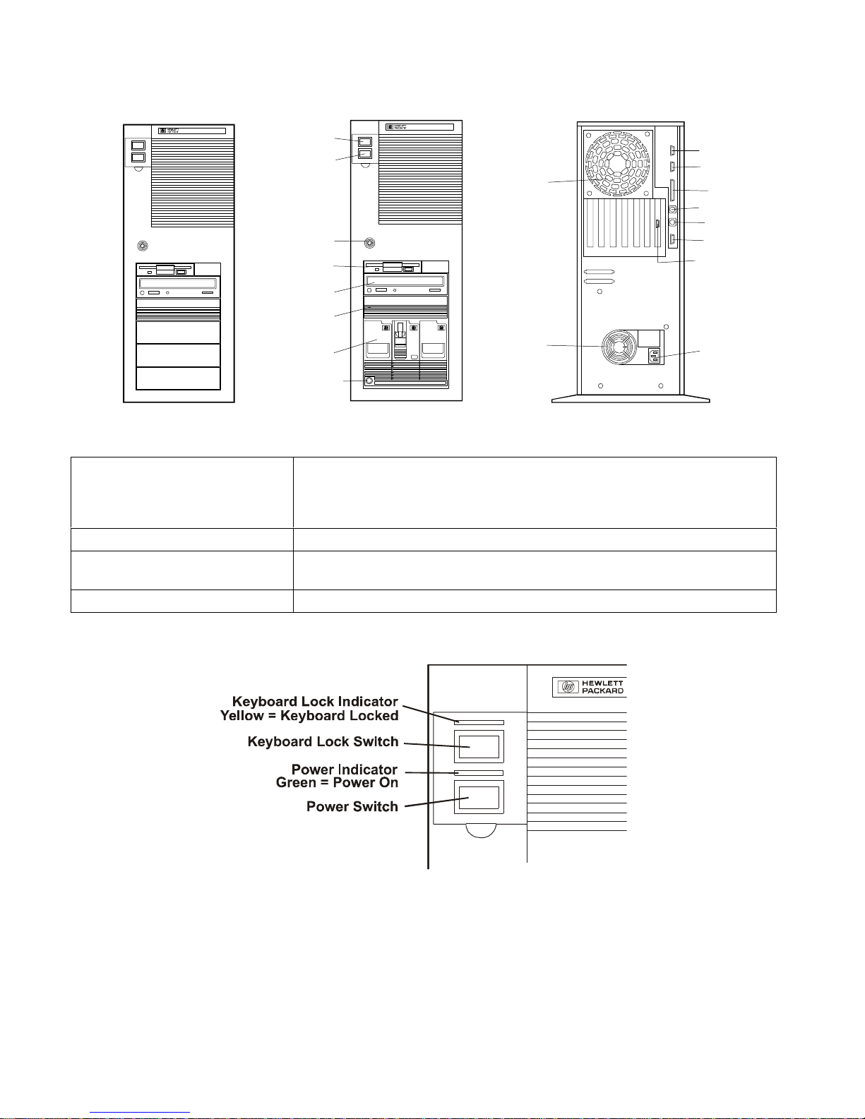
HP NetServer LC 3 System Information
Power Switch
Keyboard Lock
Lock
Flexible
Disk Drive
EIDE CD-ROM
Shelf 3
Hot Swap Drive Bay
Hot Swap Drive Bay Lock
Fan
Fan
Serial Port B
Serial Port A
Parallel Port
Mouse Port
Keyboard Port
Monitor
ManagementPort
Power
Front Control Panel
Power Switch Turns the NetServer on and off. Note that when the NetServer is turned
off, the power to the internal circuitry and mass storage devices is
disabled; however, AC power is still applied to the power supply. Always
disconnect the power cord before removing the cover.
Power Indicator Lights green when the NetServer is on.
Keyboard Lock Switch Prevents unauthorized use of the keyboard. Press the keyboard lock
button to lock the keyboard. Enter the password to unlock the keyboard.
Keyboard Lock Indicator Lights yellow when the keyboard is locked.
1
Page 4
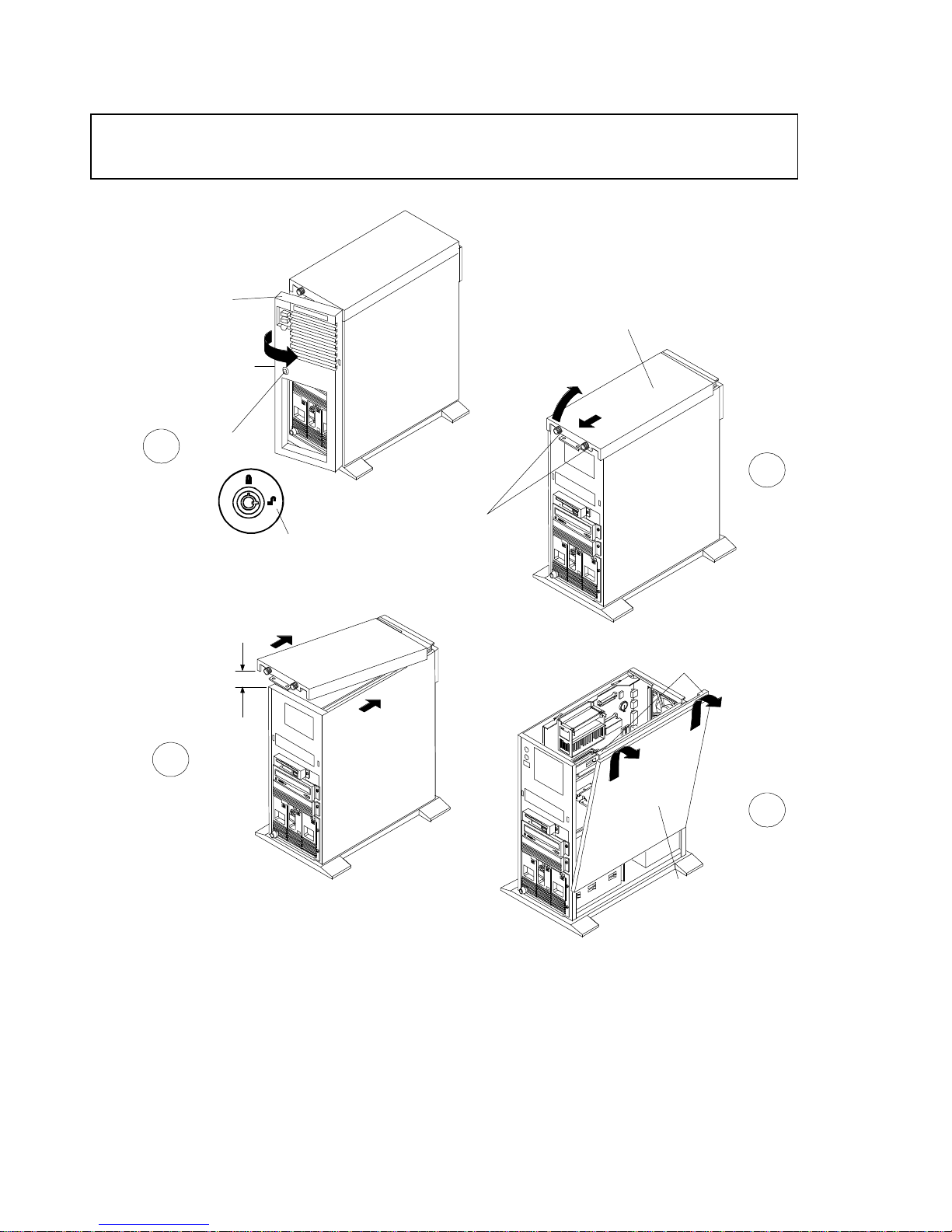
Removing the Covers
CAUTIONThe covers are an integral part of the server. The server must be operated with the
covers in place to ensure proper airflow for continued reliability and to maintain
compliance with radio frequency interference and safety standards.
1
3
Front
Bezel
Pocket
Key Lock
Unlocked Position
1 inch
(3 cm)
Top
Cover
2
Thumbscrews
Tabs
2
4
Side
Cover
Page 5
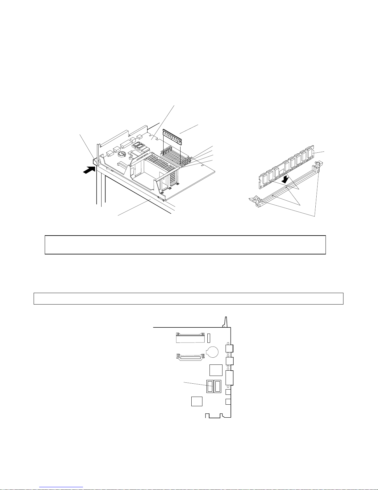
Memory
SystemBoard
M
There are four DIMM sockets on the system board for memory expansion Follow these simple rules when you plan to
install additional memory DIMMs:
• Use only HP DIMMs listed on the Technical Reference Label located inside the HP NetServer top cover,
in Information Assistant, or in Order Assistant.
• DIMMs can be 32 MB, 64 MB, or 128 MB in any combination.
• DIMMs can be installed in any order in any of the four DIMM sockets.
Crosspiece must be OFF
of the work surface
Static dissipatingwork surface
DIMM
DIMM Slot 3
DIMM Slot 2
DIMM Slot 1
DIMM Slot0
Retaining Clips
CAUTIONOnly install DIMMs on a system board that is lying flat on a static-dissipating work surface.
Do not rock the DIMM into place, but apply firm and even pressure directly downward.
Video Memory
Expand video memory by installing two 256 K x 16 (512 KB), 70 Ns, 40-pin SOJ package DRAM ICs.
CAUTION Install the chip in the correct orientation. Failure to do so will destroy the DRAM..
DIM
Notches
Keys
Video
Slots
3
Page 6
Boot Device Priority
Syste
m
32-bitPCI
The boot device priority is controlled by the Boot Device Ordering submenu of the Configuration menu of the Setup
utility.
• IDE CD-ROM drive with bootable CD-ROM
• Flexible Disk with bootable flexible disk
• Embedded SCSI controller
• PCI boards in slots in the following order: 6, 5, 4, 3, 2, 1.
• Hard Drive Priority: Allows you to rearrange the order in which hard disk drives are searched for the operating
system. All hard disk drives in the system are listed, as well as any bootable ISA board.
Backplane:
DIMM Slot LED Blink Codes
System Board
Board
Slot
PCI 6 - 32-bit
PCI 5 - 32-bit
PCI 4 - 32-bit
PCI 3 - 32-bit
PCI 2 - 32-bit
PCI 1 / ISA 16-bit ISA or
LED 0
LED 1
LED 2
LED 3
Processor Error Codes
Processor errors are indicated by blinking patterns of the DIMM slot LEDs that alternate at 1 Hz, as listed below:
Processor Error Status Indications
² = LED off
O = LED on
LED LED LED LED
0 1 2 3
4
Error Condition Action
Page 7

² O O O
9
O ² ² ²
O ² O O
² O ² ²
Voltage Regulator Module for
Primary CPU Bad
Voltage Regulator Module for
Secondary CPU Bad
Check that primary voltage regulator
module (VRM) is correctly seated. If
problem persists, replace VRM.
Check that secondary voltage
regulator module (VRM) is correctly
seated. If problem persists, replace
VRM.
² O O ²
O ² ² O
O O ² ²
² ² O O
CPU Over Temperature Check fan for function. Turn off
system, wait 20-25 minutes for system
to cool, and restart system.
CPU or Terminator Board Not
Installed
Install CPU in primary CPU slot and
CPU or terminator board in secondary
CPU slot.
DIMM Status Error Codes
When no processor error condition exists, the DIMM slot LEDs display the status of the DIMMs in the corresponding
slots, as follows:
• OFF: no DIMM installed
• Flashes ON and OFF at 1 Hz in 50/50 proportion of time: uncorrectable error or inappropriate DIMM
• Flashes ON and OFF at 1 Hz in 90/10 proportion of time: non-HP DIMM installed
• ON: HP DIMM installed
Exploded Views
10
2
15
1
14
13
12
11
3
4
5
7
8
6
5
Page 8

21
20
19
22
18
23
17
6
16
Page 9

28
27
26
25
29
30
24
7
Page 10

HP NetServer Replaceable Parts List
Fig Description Replacement Exchange
1
Chassis Assembly Not orderable
2
Top Cover 5064-1987
3
Side Cover 5064-1986
4
Cage Assy, Hot-Swap Mass Storage 5063-5671
5
Light Pipe 5041-1099
6
Backplane PCA, Hot-Swap Cage D3604-63003
7
Hot Swap Cage Bezel 5042-2108
8
Hot Swap Cage Bezel lock 5064-3503
9
tray, Hot Swap, D3349B D3583-69004
10
11a
11b
12
13
14
15
16
17
18a
18b
18c
18d
*
*
19
20
21
22a
22b
23a
23b
23c
24
25
*
26
27
28
5 1/4 inch tray, HDD D2198B
3 pack
4.2 GB SCSI HDD D4910-63001 D4910-69001
9.1 GB SCSI HDD D4911-63001 D4911-69001
5 ¼", removable media
D2199A
3 pack
CD-ROM Drive D4383-60041
1.44 MB 3.5" Floppy Disk Drive D2035-60282
3.5 inch rail kit D2198B
Backplane PCA D4906-63002 D4906-69002
Terminator PCA, Processor Slot 5183-3418
Pentium II 350 Processor Chip 1821-4201
Pentium II 400 Processor Chip 1821-4202
Pentium II 450 Processor Chip 1821-4203
Pentium III 500 Processor Chip D7129-63001 D7129-69001
Heatsink 5183-2471
Heatsink clip 5183-2472
Video Memory, 256Kx16, 50ns 1818-6527
Battery 3 volts 1420-0356
Voltage Regulator Module (VRM) 0950-2848
LC 3 System Board PCA D6123-63000 D6123-69000
Stiffener, System Board, w/extractors 5064-3501
Memory SDRAM,64MB,ECC,100MHZ D6097-63000 D6097-69000
Memory SDRAM,128MB,ECC,100MHZ D6098-63000 D6098-69000
Memory SDRAM,256MB,ECC,100MHZ D6099-63000 D6099-69000
Power Supply 5064-1942 5064-1941
System Fan 5064-1954
Rivets, Plastic, for mounting fan 5042-2110
Retainer for Adapter Board Guide 5042-2163
Guide, Adapter Board 5042-2163
Control Panel PCA 5064-1979
C2260-60078
5002-3748
Single
Single
8
Page 11

29
Front Bezel Assy. 5064-1961
30
Pedestal 5041-5339
*
Cable, Non-Hot-Swap SCSI (Wide) 5183-2182
*
Cable, IDE CD-ROM Drive 5183-2411
*
Cable, Floppy Disk Drive 5183-2410
*
Cable, Hot-Swap SCSI (Wide) 5183-2484
Cable, Array SCSI (Wide) 5183-3488
*
Cable, I2C 5182-6730
*
Cable, Serial Management 5064-1957
*
Network Adapter PCA, 100BaseT D5013-63002
*
Filler Assy, Hot-Swap 5063-8391
*
Upper Drive Filler Panel 5063-8389
*
Hot Swap Cage key 5182-4534
*
External Battery, 3.6V 1420-0559
**
HP Navigator CD-ROM
**
Diagnostic Assistant Diskette
* This part is not on the exploded view.
** This part number is constantly revised. When you order the CD-ROM, you will be sent the latest revision.
Keyboards
Language Part Number Language Part Number
US D4950-63001 Danish D4950-63016
Arab/French D4950-63025 Fr.Canadian D4950-63002
Portuguese D4950-63027 German D4950-63003
Cyrillic D4950-63030 Spanish D4950-63004
Belgian/Flemish D4950-63014 French D4950-63005
Italian D4950-63017 Norwegian D4950-63009
Arab/English D4950-63020 Swiss D4950-63011
Korea/Hangu D4950-63021 Swedish D4950-63012
Taiwan D4950-63023 UK D4950-63013
Poland D4950-63035 Czech D4950-63036
Hungarian D4950-63037 Greek D4950-63032
Turkish D4950-63035 Dutch D4950-63006
Power Cords
Country Part Number Country Part Number
Australia/New Zealand 8120-1369 India/South Africa 8120-4211
Canada/United States 8120-1751 Japan 8120-4753
Denmark 8120-2956 Switzerland 8120-2104
Europe 8120-1689 United Kingdom 8120-1351
9
Page 12

Mass Storage Cables
PowerLE
D
Cabling Label Location Description Part Number
A System backplane SCSI
connector to upper-shelf SCSI
5-connector, wide (68-pin) SCSI
cable w/built-in terminator
devices
B
System backplane IDE
3-connector IDE cable 5183-2411
connector to IDE devices (CDROM or other)
C System backplane floppy
2-connector floppy disk cable 5183-2410
connector-to-floppy disk drive
D
System backplane (or
NetRAID controller) SCSI
3-connector, wide (68-pin) SCSI
cable
connector-to- hot-swap
backplane
E I2C cable, system backplane to
2-connector I2C (3-pin) cable 5182-6730
hot-swap backplane
F
System backplane SCSI
connector-to-upper shelf SCSI
2-connector, wide (68-pin) SCSI
cable w/built-in terminator
devices
G For connecting any 68-pin
SCSI cable to 50-pin device
SCSI wide (68-pin)-to-narrow (50-
pin) adapter
Hot-Swap Hard Disk Drive LED Status and Activity Indicators
5183-2412
5183-2484
Available with
NetRAID
controller only
5183-4550
Yellow = power on
Keyboard lock LED
Yellow = keyboard locked
Hot Swap Model Only
Flexible disk drive activity light
Yellow or Green = disk drive active
CD-ROM drive activity light
Green = power on
Yellow = drive active
Blinking = drawer opening or closing
Hard disk status light
Green = drive powered on
Flash yellow = driveerror
All drivesflashing simultaneously
Flash yellow = temperature warning
Flash red = temperatureemergency
Hard diskactivity light
Green = drive active
10
Page 13

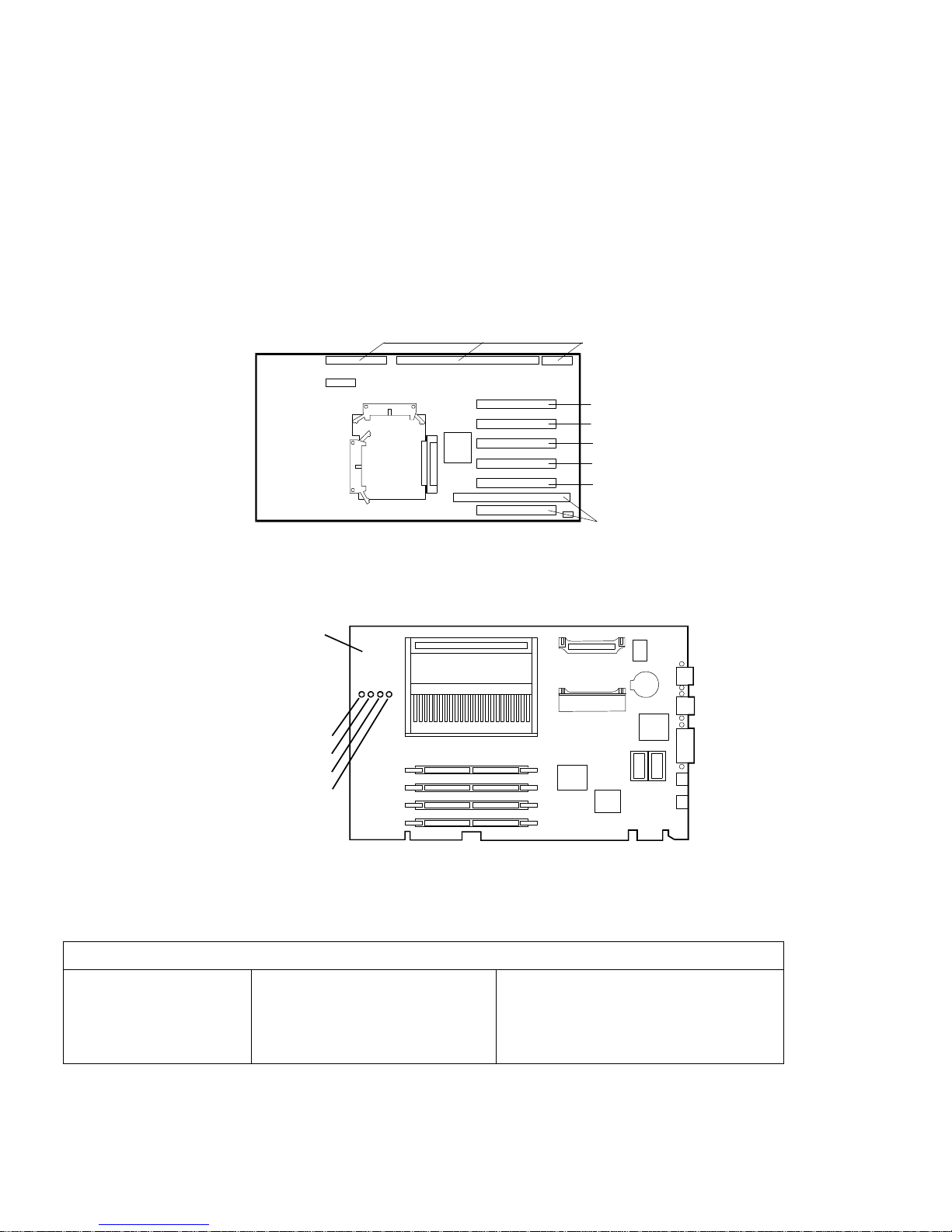
System Board Illustration
Secondary
Retaining
Latches
Primary
Processor
* J25:100 MHz
Processor Socket
(Terminator Installed
In Dual-Ready
Configurations)
* Processor
Fan
Primary VRM
Secondary
VRM Socket
* J20: N/C
System
Configuration
Switches
* J17: N/C
Diagnostic LEDs
* J26: N/C
Memory DIMM
Sockets
System Switches
0112233
0
* Cable connectors labeled with function.
Configuration jumpers labeled with default setting.
N/C = no jumper header or cable installed.
CAUTION:
On=Clear config
5
On=Clear p/w
6
Always off
7/8
Jumper settingsother than those displayed here
may result in unreliable performance or component
damage.
Battery
VideoMemory
Upgrade Sockets
Processor Speed
1
Switch
2
3
4
Processor speed
100 MHz Bus Speed
OFF
ONOFF
OFF
OFF
450
OFF
ON
OFF
ON
300 350 400
OFF
OFF
OFF
ON
ON
ON
OFF
11
Page 14

Specifications
Operating Temperature
Non-operating Temperature
Operating Humidity
(noncondensing)
Non-operating Humidity
(noncondensing)
Operating Altitude
Non-operating Altitude
Height
Width
Depth
Weight
Power supply input voltage
Power supply output
Power Consumption
BTUs
5° to 35° C (41° to 95° F)
-40° to +70° C (-40° to +158° F)
20% to 80% relative humidity
90% relative humidity
3,045 m (10,000 ft)
12,180 m (40,000 ft)
530 mm (21 in)
217 mm (8.6 in)
580 mm (23 in)
22 - 25 kg (48 - 55 lb.) depending on configuration
Auto-Ranging Power Supply
100 to 127 VAC at 4.7amps
200 to 240 VAC; 2.3 amps at 47/63 Hertz
350 Watts maximum
470 Watts maximum
1604 BTU/per hour maximum
12
Page 15

Notes:
13
Page 16

Page 17

1
 Loading...