

Page 1
Familiarization Guide
This guide is for experienced technicians who have already
completed an HP PC family training course. It is a selfpaced training guide designed to train you to repair the PC.
It contains information specific only to the repair of these
PCs. For more information about upgrading the PC, refer
to the documentation supplied with the PC or to HP’s Support Web site at http://www.hp.com/go/thinclientsupport.
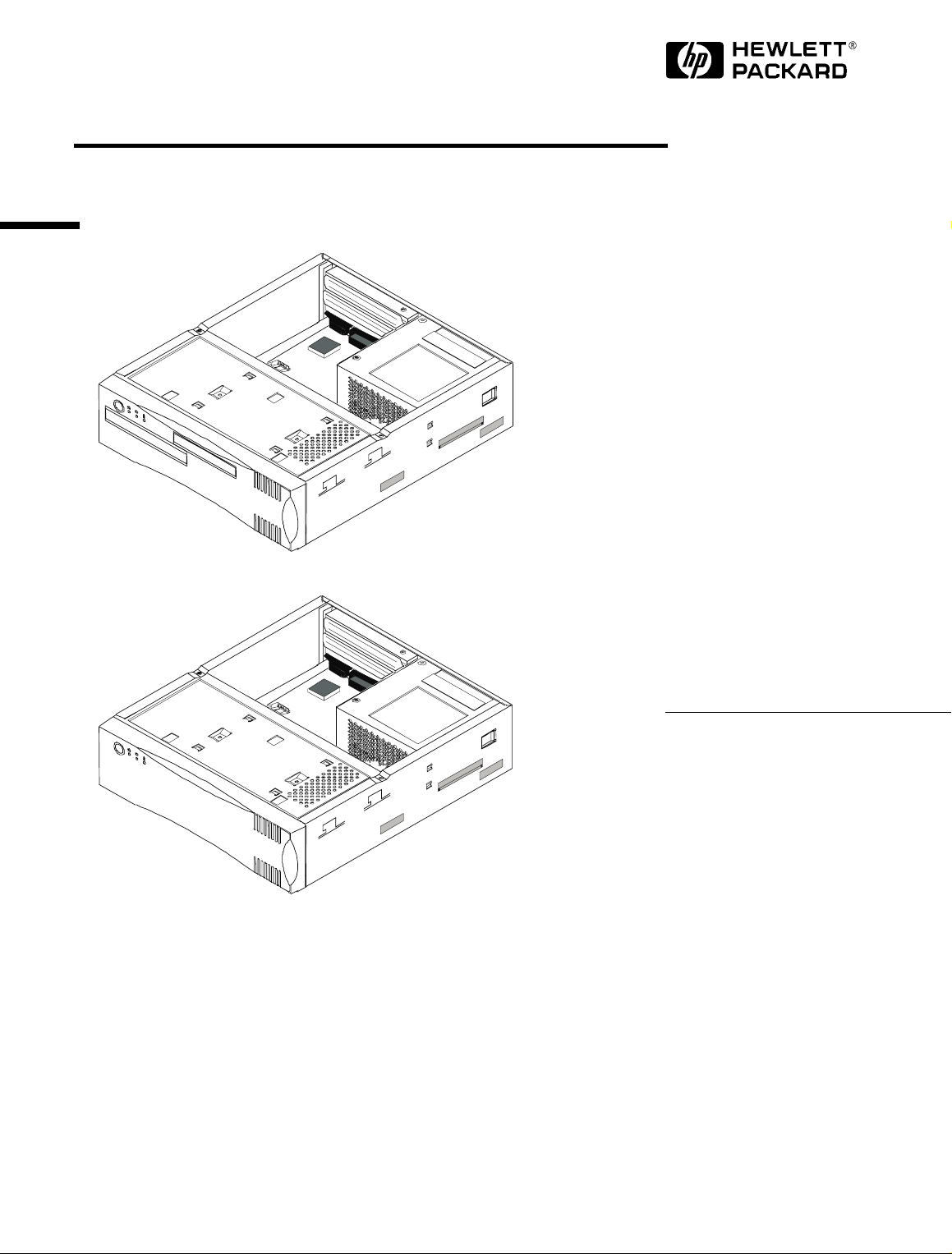
HP Small PC 20
HP Net PC 20
Page 2

Notice
The information contained in this document is subject to change without notice.
Hewlett-Packard makes no warranty of any kind with regard to this
material, including, but not limited to, the implied warranties of
merchantability and fitness for a particular purpose.
Hewlett-Packard shall not be liable for errors contained herein or for incidental
or consequential damages in connection with the furnishing, performance, or use
of this material.
This document contains proprietary information that is protected by copyright.
All rights are reserved. No part of this document may be photocopied,
reproduced, or translated to another language without the prior written consent
of Hewlett-Packard Company.
Windows® is a U.S. registered trademark of the Microsoft Corporation.
TM
Celeron
Intel Corporation.
is a trademark, and Pentium® is a U.S. registered trademark of the
Hewlett-Packard France
Thin Client Operation
38053 Grenoble Cedex 9
France
1998 Hewlett-Packard Company
Page 3

Contents
Electrostatic Discharge Warning . . . . . . . . . . . . . . . . . . . . . . . . . . . . . 5
Care of Hard Disk Drives . . . . . . . . . . . . . . . . . . . . . . . . . . . . . . . . . . . 6
HP PC Product Comparison. . . . . . . . . . . . . . . . . . . . . . . . . . . . . . . . . 7
Some Product Features. . . . . . . . . . . . . . . . . . . . . . . . . . . . . . . . . . . . . 9
PC Package. . . . . . . . . . . . . . . . . . . . . . . . . . . . . . . . . . . . . . . . . . . . . . 11
System Board and Backplane. . . . . . . . . . . . . . . . . . . . . . . . . . . . . . . 12
System Board Jumpers. . . . . . . . . . . . . . . . . . . . . . . . . . . . . . . . . . . . . . . 13
Removing and Replacing the Cover . . . . . . . . . . . . . . . . . . . . . . . . . 14
Removing the Front Panel Chassis . . . . . . . . . . . . . . . . . . . . . . . . . . 16
Installing a Hard Disk Drive . . . . . . . . . . . . . . . . . . . . . . . . . . . . . . . . 18
Installing a Slim CD-ROM Drive. . . . . . . . . . . . . . . . . . . . . . . . . . . . . 19
Installing a Slim Floppy Disk Drive . . . . . . . . . . . . . . . . . . . . . . . . . . 21
Installing Memory Modules . . . . . . . . . . . . . . . . . . . . . . . . . . . . . . . . 23
Removing and Replacing the Power Supply Unit . . . . . . . . . . . . . . 24
Removing and Replacing the System Board. . . . . . . . . . . . . . . . . . . 25
Support Features . . . . . . . . . . . . . . . . . . . . . . . . . . . . . . . . . . . . . . . . . 26
Flashing the Latest Version of the System BIOS. . . . . . . . . . . . . . . . . . . 26
Accessing the BIOS Setup Program. . . . . . . . . . . . . . . . . . . . . . . . . . . . . 26
Viewing Power On Self Test (POST) Information. . . . . . . . . . . . . . . . . . 26
Troubleshooting . . . . . . . . . . . . . . . . . . . . . . . . . . . . . . . . . . . . . . . . . . . . 26
3
Page 4

Contents
Where to Find More Information. . . . . . . . . . . . . . . . . . . . . . . . . . . . 27
Complete the Questionnaire to Check Your Understanding . . . . . 28
Answers and Explanations. . . . . . . . . . . . . . . . . . . . . . . . . . . . . . . . . 29
4
Page 5

Electrostatic Discharge Warning
Electrostatic Discharge Warning
Electrostatic Discharge (ESD) can damage processors, memory, disks, accessory
boards and other components.
When installing or replacing a component:
Do not take the new component out of its ESD package before connecting your
1
wrist strap and ESD mat to a suitably earthed (grounded) point.
Do not forget to use the ESD package provided with the new part to return the
2
old part. The ESD package is conductive and is easy to recognize from its label.
ESD Label
5
Page 6
Care of Hard Disk Drives
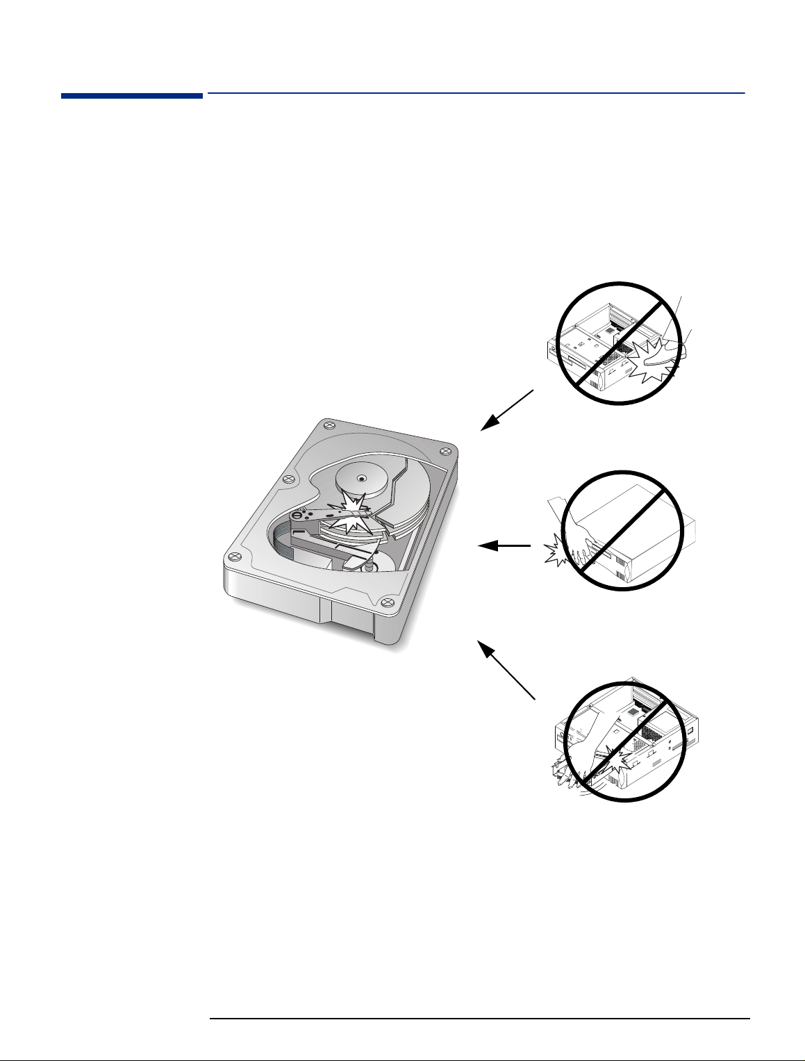
Care of Hard Disk Drives
Hard disk drives are delicate and are very sensitive to shocks or vibration. When
installing a hard disk accessory, be careful not to drop or knock the drive. Any
shock may damage the drive and prevent it from functioning correctly.
Hard disk drives already installed in HP PCs are also sensitive to shocks. If the
PC’s system unit is knocked or dropped accidentally, this may cause damage to
installed hard disk drives.
Avoid striking the PC
Don’t move the PC
when powered on
Don’t knock the hard
disk during installation
6
Page 7
HP PC Product Comparison
HP PC Product Comparison
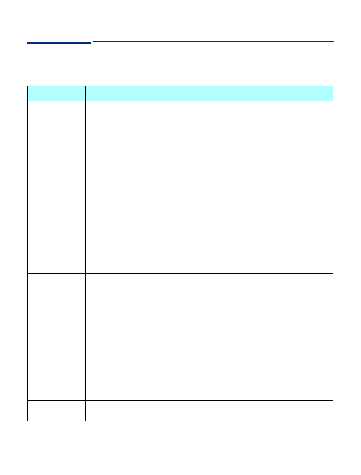
The following table shows the product features of the HP Small PC 20 / HP Net
PC 20 and the HP Vectra VE 8 PC.
Component HP Vectra VE 8/xxx PC HP Small PC 20 / HP Net PC 20
Microprocessor
Chipset
Memory
Intel Pentium® II for Slot 1, 266, 333, 350, or
400 MHz, 32 KB of level-1 cache memory, 512
KB of level-2 cache memory
Intel 440BX AGPset, 66 or 100 MHz bus speed.
●
AGP-enabled (Accelerated Graphics Port) for
enhanced graphics performance in Intel Pentium
II-based systems
●
ACPI (Advanced Configuration and Power
Interface) support
●
Ultra DMA/33 hard disk support (on Primary
and Secondary IDE channels)
●
SDRAM memory allows real-time data transfer
from the processor, eliminating bottlenecks and
improving overall system performance
32 or 64 MB installed, 384 MB maximum of nonECC SDRAM in three DIMM sockets
Intel Pentium II for Slot 1, 333 MHz, 32 KB of
level-1 cache memory, 512 KB of level-2 cache
memory
OR
Intel Celeron
TM
, 266, 300A or 333 MHz, 32 KB
of level-1 cache memory, 128 KB of level-2
cache memory in 300A and 333 MHz models, 0
KB of level-2 cache in 266 MHz models
Intel 440EX AGPset, 66 MHz bus speed.
●
AGP-enabled (Accelerated Graphics Port) for
enhanced graphics performance in Intel Pentium
II and Celeron-based systems
●
ACPI (Advanced Configuration and Power
Interface) ready
●
Ultra DMA/33 hard disk support
●
SDRAM memory allows real-time data
transfer from the processor, eliminating
bottlenecks and improving overall system
performance
32, 64, or 128 MB installed, 256 MB maximum
of non-ECC SDRAM in two DIMM sockets
Hard Disks
Flexible disk drive
CD-ROM
Audio Interface
LAN Interface
Graphics
Operating Systems
3.2, 4.3, or 6.4 GB Ultra ATA SMART II 3.2 or 6.4 GB Ultra ATA SMART
3.5-inch, 1.44 MB capacity Slim 3.5-inch, 1.44 MB capacity (some models)
32X IDE (some models) 12.7 mm Slim 24X IDE (some models)
Sound Blaster Pro compatible (Aztech) audio
board (some models)
Integrated ISA-based CrystalClear CS4235 3D
Sound Blaster, Sound Blaster Pro and Windows
Sound System compatible
3Com 905B-TX or Intel 10/100Base-T LAN board Integrated Intel 10/100BT with RPO/WuOL
Matrox Productiva M100 AGP board, 4 MB EDO
(not upgradeable) on AGP bus
Integrated AGP-based ATI RAGE IIC/PRO AGP
controller with onboard 4 MB SGRAM (not
upgradeable)
Windows NT4 (Service Pack 3) or Windows 95
Windows NT 4, Windows 95 or Windows 98
(SR 2.5)
7
Page 8

HP PC Product Comparison
Component HP Vectra VE 8/xxx PC HP Small PC 20 / HP Net PC 20
Connectors 2 serial, 1 parallel, keyboard, mouse, 2 stacked
USB, 15-pin VGA
Expandability
(desktop)
5 drive shelves: 3 front-access and 2 internal
Accessory Slots: 4 PCI, 1 ISA,
1 ISA/PCI combination
Expandability
(minitower)
6 drive shelves: 4 front-access and 2 internal
Accessory Slots: 4 PCI, 1 ISA,
1 ISA/PCI combination
BIOS
Power Supply
AMI standard BIOS AwardBIOS with 2 MB Flash EEPROM, DMI 2.0
Manually switched 115/230 VAC, 145 W
continuous output
Input/Output Cables
Primary IDE cable: Ultra ATA
Secondary IDE (CD-ROM) cable: Standard IDE
Floppy disk drive cable
Note: both IDE channels are Ultra ATA
2 serial, 1 parallel with ECP/EPP, keyboard,
mouse, 2 USB, 1 RJ45 LAN, 1 D-sub 15-pin
VGA, 3 audio: 1 Mic-in, 1 Line-in, and 1 Line-out
3 drive shelves: 2 front-access and 1 internal
Accessory slots: 1 PCI and 1 PCI/ISA
combination. (The HP Net PC 20 does not have
an ISA slot.)
(The minitower model is the same as the
desktop model, but on a stand.)
compliant
100 to 240 VAC (manually switched), 85 Watt
Primary IDE cable: Ultra ATA
Secondary IDE (CD-ROM) cable: Standard IDE
slim cable
Floppy disk drive cable
System Management
DMI 2.0 / SMBIOS 1.x, HP TopTools 3.0, HP
DiagTools 2.0
DMI 2.0, ACPI-ready, TopTools Console,
OpenView DTA
8
Page 9
Some Product Features
Some Product Features
Intel Celeron Processor The Intel Celeron processor 333, 300A and 266 MHz provides ideal performance
for applications running on operating systems such as Windows 95. All Intel
Celeron processors are based on Intel’s 0.25 micron CMOS process technology.
The Intel Celeron processor also benefits from the same P6 microarchitecture
core as the Pentium II processor.
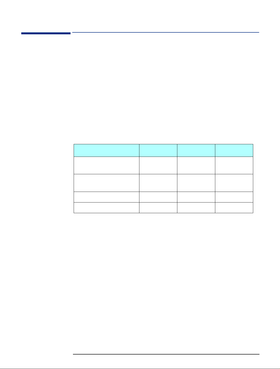
Intel 440EX AGPset
Features
Bus Details
Video: ATI RAGE IIC/PRO
AGP Chip
This Intel chipset, which is based on the Intel 440LX chipset, is optimized for
Intel Celeron processor-based systems. It provides ACPI-compliance to permit
increased manageability across the corporate network. It is AGP-enabled for
enhanced graphics performance. The chipset also provides support for Ultra
DMA/33. No Error Correcting Code (ECC) support is provided.
Bus Speed Size Transfer Rate
Host (Front Side Bus, Processor-
66 MHz 64 bit 528 MB/sec
Local, System)
AGP 66 MHz (double-
32 bit 528 MB/sec
clocked)
PCI 33 MHz 32 bit 132 MB/sec
ISA 8.25 MHz 16 bit 16 MB/sec
The system comes with an integrated AGP-based ATI RAGE IIC/PRO AGP
controller chip. This VGA controller offers output pixel data rates with noninterlaced screen resolutions of up to 1600x1200x65k colors at a refresh rate of
76Hz (4 MB). The AGP controller enables the system to have a higher
performance under Windows and other GUI (Graphics User Interface)
environments, plus optimizations which result in even more impressive 2D and 3D
performance.
The RAGE IIC/PRO delivers 3D performance unmatched in its class, along with a
comprehensive list of 3D features including perspectively correct texturing, mipmapping, bilinear and trilinear filtering, z-buffering, video texturing, Gouraud
shading, and alpha blending.
The RAGE IIC/PRO incorporates excellent video support, suitable for MPEG-2
content and video conferencing acceleration. In addition to offering increased
performance and design flexibility, the RAGE IIC/PRO adds full PCI Power
Management support.
9
Page 10

Some Product Features
Audio: CrystalClear
CS4235 Chip
LAN: Intel 82558 Chip
The onboard CrystalClear CS4235 chip includes an integrated FM synthesizer and
a Plug-and-Play interface. In addition, it includes hardware master volume control
as well as extensive power management and 3D sound technology. It is compatible
with the Microsoft Windows Sound System standard and will run software written
to the Sound Blaster and Sound Blaster Pro interfaces. It is fully compliant with
Microsoft's PC97 and PC98 audio requirements.
The onboard Intel 82558 chip is a fully integrated 10BASE-T/100BASE-TX LAN
controller. It consists of both the MAC controller and the 10/100 Mbps physical
layer interface. Its true 32-bit architecture enables it to perform high speed data
transfers on the PCI bus using four DMA channels. Its sophisticated microcodebased engine enables the 82558 chip to process high level commands and perform
multiple operations without CPU intervention. Its 3 Kbyte Transmit and Receive
FIFOs provide large on-chip storage space for both transmitted and received
frames. The 82558 chip provides full support for both half duplex and full duplex
operation, as well as support for full duplex flow control.
10
Page 11

PC Package
PC Package
Front View
12.7 mm Slim CD-ROM Drive
Power Button
Power LED
Hard Disk Drive Access LED
LAN Active LED
Floppy Disk Drive (some models)
Top View
Rear Panel Screw
Adapter Panel
Rear Panel Screw
Power Supply Connector
Power Supply Fan
Rear Panel Screws
Rear View
Microphone Jack
Line-In Jack
Line-Out Jack
USB Ports
RJ45 LAN Connector
Parallel Port
Keyboard Connector
Mouse Connector
Serial Port 2
Serial Port 1
VGA Port
Voltage Selection Switch
Front of PC
Back of PC
System Board
Front Panel Chassis
Power Supply Unit
11
Page 12

System Board
System Board and Backplane
System Board and Backplane
Connector is
on this side
Backplane
PCI/ISA
Combination
Slot
Note: The HP Net
PC 20 does not
have an ISA slot.
12
PCI Slot
ISA Slot
PCI Slot
Page 13

System Board Jumpers
System Board and Backplane
CMOS Clear:
This jumper allows you to enable or disable the CMOS clear feature.
CMOS_CLR
Function CMOS_CLR
Normal (default)
Clear
CAUTION: DO NOT boot the system with the jumper in the CLEAR position.
Flash ROM Type Select:
These two jumpers allow you to configure the flash ROM chip.
EP1, EP2
2 MB Flash ROM EP1 EP2
ATMEL AT29C020
SST 29EE020
AMD 28F020
INTEL 28F002
MXIC 28F2000
Processor Speed This jumper lets you set the processor speed.
CPU Speed
Pin Number
(Core)
7-8 5-6 3-4 1-2
233 ON ON OFF OFF
266 ON OFF ON ON
300 ON OFF ON OFF
333 ON OFF OFF ON
366 ON OFF OFF OFF
400OFFONONON
13
Page 14

Removing and Replacing the Cover
Removing and Replacing the Cover
WARNING:
Removing the Cover
For your safety, never remove the PC’s cover without first removing the power
cord from the power outlet, and any connection to a telecommunications
network. Always replace the cover before switching on the PC again.
Switch off the display and the PC.
1
Disconnect all power cords and any telecommunications cables.
2
If the PC is being used in its vertical position, remove it from its base and place
3
it on a flat and stable surface.
Base
Using a screwdriver, loosen the three screws securing the chassis cover.
4
Standing at the back of the PC, grasp the cover with both hands. Slide the
5
cover towards you and pull upwards until it slides off the main chassis.
To unclip the cover completely from the chassis, you may need to gently ease
the sides of the cover away from the chassis.
Gently pull the sides of the
cover away from the chassis
14
Page 15

Removing and Replacing the Cover
Replacing the Cover
1 Standing at the back of the PC, lower the cover onto the chassis and slide the
cover forwards into position.
In order to clear the chassis as you slide the cover downwards onto the PC,
you may need to gently ease the sides of the cover outwards.
As you slide the cover forwards into position, make sure that the clips on the
inside of the cover engage properly with the top of the front panel chassis and
the sides of the main chassis.
As you slide the cover into
position, press the sides
inwards slightly to help the
clips to engage
2 Using a screwdriver, tighten the three screws to secure the cover in position.
3 If the PC is going to be used in its vertical position, stand it up and place it on
its base.
15
Page 16

Removing the Front Panel Chassis
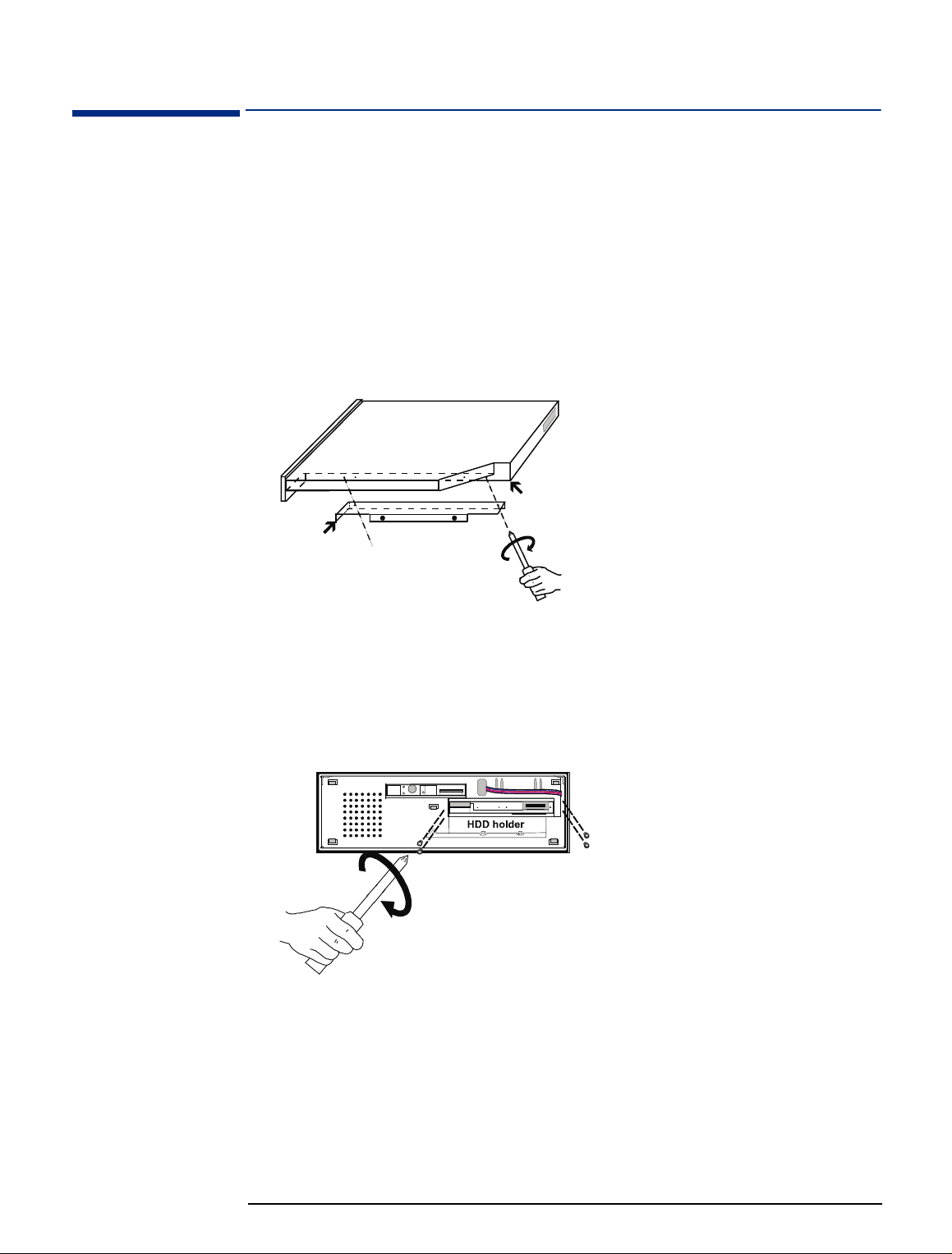
Removing the Front Panel Chassis
To gain full access to the system board you need to remove the front panel
chassis.
Removing the Front
Panel Chassis
Remove the PC’s cover as described in “Removing the Cover” on page 14.
1
Using a screwdriver, remove the two screws holding the front panel chassis in
2
place.
Disconnect any cables that run between the front panel chassis and the system
3
board, for example, the hard disk drive data and power cables.
Slide the front panel chassis away from the PC and place the chassis slightly in
4
front of the PC. If you have not disconnected the cables from the system board,
take care not to put any strain on the cables as you slide the front panel chassis
clear of the PC.
16
Page 17

Removing the Front Panel Chassis
Replacing the Front
1 Push the front panel chassis slightly into the main chassis.
Panel Chassis
CAUTION: Take great care with the cables, especially the hard disk drive data cable, when
you slide the front panel chassis into the main chassis.
2 Reconnect any cables running between the front panel chassis and the system
board.
3 Make sure that the front panel chassis is as far into the main PC chassis as it
will go, and then secure the front panel chassis in position.
17
Page 18

Installing a Hard Disk Drive
Installing a Hard Disk Drive
To install a hard disk drive, take the following steps.
Remove the cover (refer to “Removing the Cover” on page 14).
1
Remove the front panel chassis (refer to “Removing the Front Panel Chassis”
2
on page 16).
Slide the new hard disk drive on to the hard disk drive shelf and, using the four
3
screws supplied with the drive, secure the drive in position.
Connect the IDE cable and the power supply cable to the hard disk drive.
4
Hard disk drive
Red edge Pin 1
Place the front panel chassis slightly in front of the main chassis.
5
Connect the other end of the IDE cable to the PRIMARY connector on the
6
system board (refer to “System Board and Backplane” on page 12).
Connect the power cable coming from the back of the hard disk drive to the
7
HDD_PW connector on the system board (refer to “System Board and
Backplane” on page 12).
Replace the front panel chassis (refer to “Replacing the Front Panel Chassis”
8
on page 17).
Replace the cover (refer to “Replacing the Cover” on page 15).
9
18
Page 19
Installing a Slim CD-ROM Drive
Installing a Slim CD-ROM Drive
To install a Slim CD-ROM drive, take the following steps.
Remove the cover (refer to “Removing the Cover” on page 14).
1
Remove the front panel chassis (refer to “Removing the Front Panel Chassis”
2
on page 16).
Attach the L-shaped metal bracket by matching the two screw holes of the
3
metal bracket with the first and last screw holes of the group of four screw
holes on the right underside portion of the CD-ROM drive and securing the two
screws to it.
First and last screw hole on the right
underside portion of the CD-ROM drive
L-shaped metal
bracket
If this is the first time that a CD-ROM is being installed in the PC, remove the
4
front panel plastic cover from the CD-ROM drive bay by pushing outwards
from the inside with your fingers.
Slide the new CD-ROM drive onto the CD-ROM drive shelf and, using the
5
screws provided with the drive, secure the drive in position.
Attach the CD-ROM drive adaptor to the CD-ROM drive adaptor connector
6
located at the back of the CD-ROM drive by:
first securing the copper hexagonal bolt to the rear of the CD-ROM drive by
a
hand, and
securing the two mini-screws from the CD-ROM drive adaptor into the cop-
b
per hexagonal bolt with a mini-screwdriver.
19
Page 20

Installing a Slim CD-ROM Drive
7 Connect one end of the CD-ROM drive cable onto the CD-ROM drive.
Pin 1
Red edge
8 Place the front panel chassis slightly in front of the main chassis.
9 Connect the other end of the CD-ROM drive cable to the CD_ROM connector
on the system board (refer to “System Board and Backplane” on page 12).
10 Replace the front panel chassis (refer to “Replacing the Front Panel Chassis”
on page 17).
11 Replace the cover (refer to “Replacing the Cover” on page 15).
20
Page 21

Installing a Slim Floppy Disk Drive
Installing a Slim Floppy Disk Drive
To install a slim floppy disk drive, take the following steps.
Remove the cover (refer to “Removing the Cover” on page 14).
1
Remove the front panel chassis (refer to “Removing the Front Panel Chassis”
2
on page 16).
If the floppy disk drive is not already connected to its tray, connect it now.
3
Front of floppy
disk drive
4 screws (2 on either side) to connect the floppy
disk drive to the floppy disk drive tray
Side view of floppy disk drive and
floppy disk drive tray
By pushing outwards from the inside with your fingers, remove the floppy disk
4
drive plastic filler panel from the front bezel. If you need to remove the front
bezel to do this then do so by unclipping the bezel from the front panel chassis.
Floppy disk drive plastic filler panel
5 clips used to connect the front
bezel to the front panel chassis
21
Page 22

Installing a Slim Floppy Disk Drive
5 Slide the floppy disk drive (connected to its tray) into the front panel chassis
and secure the drive in position using the 3 screws supplied with it.
2 screws to secure the floppy disk drive
4 hooks (2 on either side) to connect the floppy
disk drive tray to the front panel chassis
Front panel chassis
Front of front
panel chassis
Floppy disk drive
and tray
tray to the top of the front panel chassis
Slim CD-ROM drive
Hard disk drive
1 screw to secure the floppy
disk drive tray to the CD-ROM
drive tray
6 If you removed the front bezel earlier, clip it back into position now.
7 Connect one end of the floppy disk drive cable to the floppy disk drive.
8 Place the front panel chassis slightly in front of the main chassis.
9 Carefully connect the other end of the floppy disk drive cable to the FDD
connector on the system board (refer to “System Board and Backplane” on
page 12).
10 Replace the front panel chassis (refer to “Replacing the Front Panel Chassis”
on page 17).
11 Replace the cover (refer to “Replacing the Cover” on page 15).
22
Page 23

Installing Memory Modules
Installing Memory Modules
Inserting a Memory
Module
To install a memory module, take the following steps.
Remove the cover (refer to “Removing the Cover” on page 14).
1
Remove the front panel chassis (refer to “Removing the Front Panel Chassis”
2
on page 16).
Locate the DIMM slots on the system board (refer to “System Board and
3
Backplane” on page 12).
Insert the memory module into the DIMM slot. When the module touches the
4
bottom of the slot, the clip on each end of the slot will close to secure the
module in position.
Memory modules are not symmetrical they will only fit into the DIMM slot in one
direction.
If you are installing modules in both DIMM slots, repeat step 4 for the second
5
memory module.
Removing a Memory
Module
Replace the front panel chassis (refer to “Replacing the Front Panel Chassis”
6
on page 17).
Replace the cover (refer to “Replacing the Cover” on page 15).
7
To remove a memory module, press the two retaining clips downwards. This lifts
the module up and out of the slot.
23
Page 24
Removing and Replacing the Power Supply Unit
Removing and Replacing the Power Supply Unit
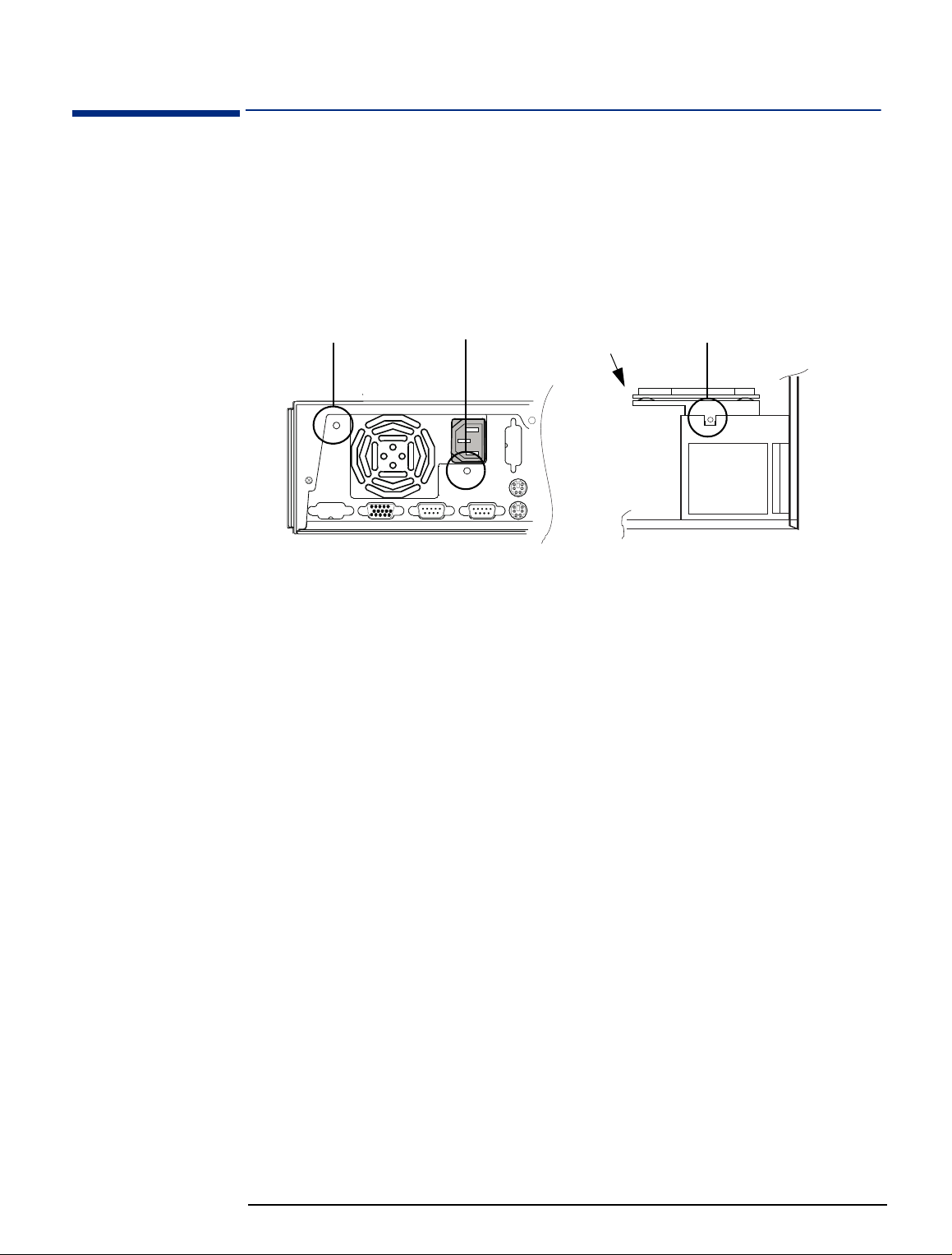
Removing the Power
Supply Unit
Remove the cover (refer to “Removing the Cover” on page 14).
1
Disconnect the power cable from the AT_PWR connector on the system board
2
(refer to “System Board and Backplane” on page 12).
Remove the three securing screws from the power supply unit.
3
1
View from back
Carefully remove the backplane from the system board.
4
Lift the power supply unit clear of the PC.
5
2
Backplane
3
Back of PC
View from top
Replacing the Power
Supply Unit
Place the power supply unit in the PC.
1
Connect the backplane to the system board and then, using the screw you
2
removed earlier, secure the backplane to the power supply unit.
Replace the two screws at the back of the PC.
3
Reconnect the power supply cable coming from the power supply unit to the
4
system board.
Replace the cover (refer to “Replacing the Cover” on page 15).
5
24
Page 25

Removing and Replacing the System Board
Removing and Replacing the System Board
Before Replacing the
System Board
Replacing the System
Board
If there is a problem with the PC and you think it may be due to the system board,
then, before replacing the board with a new one, carry out the following checks:
• Check that the latest driver versions have been installed.
• Check that the latest BIOS version has been installed.
• Check that the problem isn’t described in the product bug list.
• Make sure that you are electrostatically grounded.
Remove the cover (refer to “Removing the Cover” on page 14).
1
Remove the front panel chassis (refer to “Removing the Front Panel Chassis”
2
on page 16).
Make sure that there are no cables connected to the system board.
3
Remove the power supply unit (refer to “Removing and Replacing the Power
4
Supply Unit” on page 24).
Remove the six retaining screws from the system board.
5
Six retaining
screws
System board
Installing a New System
Board
Back of PC
Remove the system board from the PC.
6
Carefully insert the new system board in the PC.
1
Replace the retaining screws.
2
Replace the power supply unit (refer to “Replacing the Power Supply Unit” on
3
page 24), making sure that you reconnect all the cables you disconnected
earlier.
Replace the front panel chassis (refer to “Replacing the Front Panel Chassis”
4
on page 17).
Replace the cover (refer to “Replacing the Cover” on page 15.
5
Front of PC
25
Page 26

Support Features
Support Features
Flashing the Latest Version of the System BIOS
The System ROM can be updated with the latest BIOS firmware. This can be
downloaded from HP’s World Wide Web site:
http://www.hp.com/go/thinclientsupport
To download a BIOS upgrade, connect to the HP Web site and follow the onscreen instructions to download the flash utility programs and the BIOS file onto
a diskette.
.
For Models Without a
Floppy Disk Drive
For models that do not have a floppy disk drive installed, you need to temporarily
install a floppy disk drive in the PC (refer to “Installing a Slim Floppy Disk Drive”
on page 21) to enable the BIOS to be flashed from a floppy disk.
Once the HP Small PC 20 / HP Net PC 20 is supported by HP TopTools (which, as
of October 1998, is not the case) you can use HP TopTools to flash the BIOS. For
more information about HP TopTools, refer to the HP TopTools World Wide Web
site:
http://www.hp.com/go/manageability
.
Accessing the BIOS Setup Program
To access the BIOS Setup program, press the <DELETE> key during system
startup. The main CMOS Setup screen is displayed:
Load BIOS Defaults
To see online help for a selected field, press <F1>.
Viewing Power On Self Test (POST) Information
To view the POST screen, press <TAB> during system startup.
Troubleshooting
The “Load BIOS Defaults” option (on the opening screen of the Setup program see above) loads the troubleshooting default values permanently stored in the
BIOS ROM. These default settings are non-optimal and disable all high
performance features.
26
Page 27

Where to Find More Information
Where to Find More Information
Documentation and software can be downloaded from HP’s World Wide Web site:
http://www.hp.com/go/thinclientsupport
.
27
Page 28

Complete the Questionnaire to Check Your Understanding
Complete the Questionnaire to Check Your Understanding
Draw a circle around each letter that corresponds to a correct answer. (There
may be more than one correct answer to each question.)
Can you use a non-Ultra ATA cable with an Ultra ATA device?
1
Yes, you can use a non-Ultra ATA cable with an Ultra ATA device.
a
No, you must use an Ultra ATA cable with an Ultra ATA device.
b
What must you check before you change the system board?
2
Check that the latest driver versions are installed.
a
Check that the latest BIOS has been flashed.
b
Check that the problem you are trying to solve isn’t described in the
c
product bug-list.
Check that you are electrostatically grounded.
d
What type of BIOS is in the HP Small PC 20 / HP Net PC 20?
3
A non-modified Phoenix BIOS.
a
An AMI BIOS with full DMI 2.0 support and all HP extensions.
b
A standard AMI BIOS with DMI 2.0 support.
c
An Award BIOS.
d
It doesn’t matter, you can use any of the above.
e
The client wishes to accelerate the processing throughput of the PC. Which of
4
the following options are viable:
Replacing the current processor by a faster processor (when available).
a
Replacing the current processor by an overdrive processor
b
(when available).
Installing more main memory modules.
c
Changing the processor speed with the system board switches.
d
Which is correct? The various bus speeds on the HP Small PC 20 / HP Net PC
5
20 are:
Host bus 66 MHz, AGP bus 66 MHz, PCI bus 66 MHz, and ISA bus
a
33 MHz.
28
Host bus 100 MHz, AGP bus 33 MHz, PCI bus 33 MHz, and ISA bus
b
8 MHz.
Host bus 66 MHz, AGP bus 66 MHz, PCI bus 33 MHz, and ISA bus 8 MHz.
c
Page 29

Answers and Explanations
Answers and Explanations
Can you use a non-Ultra ATA cable with an Ultra ATA device?
1
b No, you must use an Ultra ATA cable with an Ultra ATA device. Using a
non-ATA cable may give unpredictable results and may lead to data loss.
Refer to “HP PC Product Comparison” on page 7 for more information about
the data cables used in the PC.
What must you check before you change the system board?
2
a Check that the latest driver versions are installed.
b Check that the latest BIOS has been flashed.
c Check that the problem you are trying to solve isn’t described in the
product bug-list.
d Check that you are electrostatically grounded.
You must check all four! See page 25 for more information.
What type of BIOS is in the HP Small PC 20 / HP Net PC 20?
3
d An Award BIOS.
Refer to “Support Features” on page 26 for more information about the BIOS.
The client wishes to accelerate the processing throughput of the PC. Which of
4
the following options are viable:
b Replacing the current processor by a faster processor (if available).
c Installing more main memory modules.
Unless it is an official overdrive version of the original processor, HP does not
support the replacement of a processor by a faster one, even when models
exist that use the faster processor. Installing more main memory increases
the performance of the virtual memory system. Changing the processor speed
jumpers to use a faster processor speed than that for which the installed
processor has been qualified is not supported by HP and may lead to data
loss.
Refer to “Installing Memory Modules” on page 23 for more information about
upgrading the main memory.
Which is correct? The various bus speeds on the HP Small PC 20 / HP Net PC
5
20 are:
c Host bus 66 MHz, AGP bus 66 MHz, PCI bus 33 MHz, and ISA bus 8 MHz.
Refer to “Bus Details” on page 9 for more information.
29
Page 30

Part Number : 5967-7297
 Loading...