

Page 1
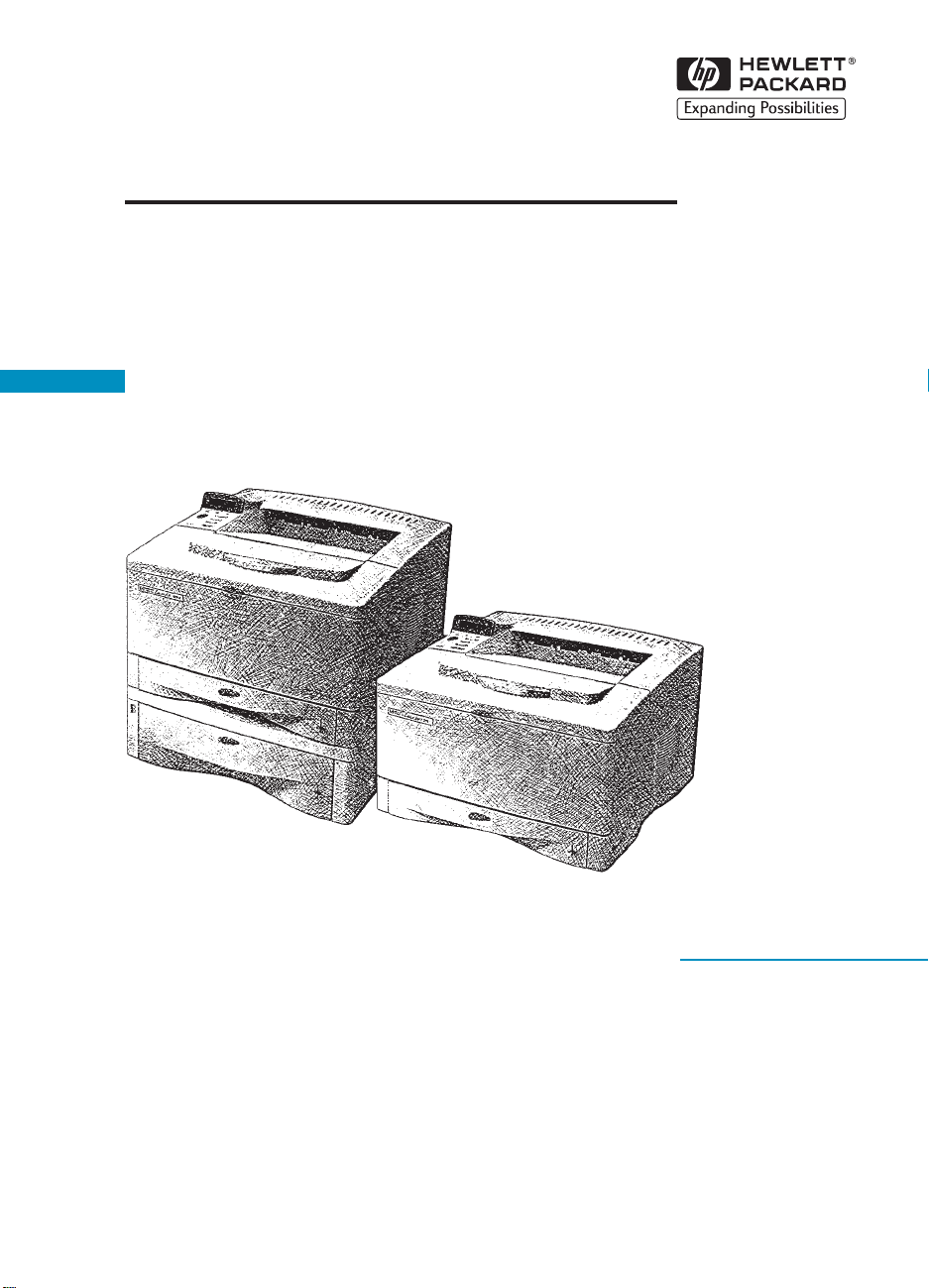
HP LaserJet 5000, 5000 N
English
and 5000 GN Printers
Service Manual
Page 2

HP LaserJet 5000, 5000 N, and
5000 GN Printers
Service Manual _____________
Page 3

© Copyright Hewlett-Packard
Company 1998
All Rights Reserved.
Reproduction, adaptation, or
translation without prior written
permission is prohibited, except
as allowed under the cop yright
laws.
Publication number
C4110-91033
First Edition
Warranty
The information contained in
this document is subject to
change without notice.
Hewlett-Packard makes no
warranty of any kind with
respect to this information.
HEWLETT-PACKARD
SPECIFICALLY DISCLAIMS
THE IMPLIED WARRANTY OF
MERCHANTABILITY AND
FITNESS FOR A PARTICULAR
PURPOSE.
Hewlett-Packard shall not be
liable for any direct, indirect,
incidental, consequential, or
other damage alleged in
connection with the furnishing or
use of this information.
Trademark Credits
PostScript
™
is a trademark of
Adobe Systems Incorporated
which may be registered in
certain jurisdictions.
™
CompuServe
is a U.S.
trademark of CompuServe, Inc.
®
Windows
is a U.S. registered
trademarks of Microsoft
Corporation.
™
TrueType
is a U.S. trademark
of Apple Computer, Inc.
NERGY STAR
E
®
is a U.S.
registered service mark of the
U.S. EPA.
Hewlett-Packard Company
11311 Chinden Boulevard
Boise, Idaho 83714 U.S.A.
Page 4

Contents
1 Printer Description
Overview . . . . . . . . . . . . . . . . . . . . . . . . . . . . . . . . . . . . . . . . . . .1-1
Printer Features. . . . . . . . . . . . . . . . . . . . . . . . . . . . . . . . . . . . . . 1-2
Identification . . . . . . . . . . . . . . . . . . . . . . . . . . . . . . . . . . . . . . . . 1-5
Model and Serial Numbers . . . . . . . . . . . . . . . . . . . . . . . . . .1-5
Site Requirements. . . . . . . . . . . . . . . . . . . . . . . . . . . . . . . . . . . . 1-6
Space Requirements . . . . . . . . . . . . . . . . . . . . . . . . . . . . . .1-7
Paper Specifications . . . . . . . . . . . . . . . . . . . . . . . . . . . . . . . . . 1-11
Supported Types of Paper . . . . . . . . . . . . . . . . . . . . . . . . . 1-14
Guidelines for Using Paper. . . . . . . . . . . . . . . . . . . . . . . . . 1-15
Labels . . . . . . . . . . . . . . . . . . . . . . . . . . . . . . . . . . . . . . . . .1-18
Transparencies. . . . . . . . . . . . . . . . . . . . . . . . . . . . . . . . . . 1-18
Vellum. . . . . . . . . . . . . . . . . . . . . . . . . . . . . . . . . . . . . . . . . 1-18
Envelopes. . . . . . . . . . . . . . . . . . . . . . . . . . . . . . . . . . . . . . 1-19
Card Stock and Heavy Paper . . . . . . . . . . . . . . . . . . . . . . .1-20
Safety Information. . . . . . . . . . . . . . . . . . . . . . . . . . . . . . . . . . . 1-22
Laser Safety Statement . . . . . . . . . . . . . . . . . . . . . . . . . . .1-22
Canadian DOC Regulations . . . . . . . . . . . . . . . . . . . . . . . . 1-22
FCC Regulations. . . . . . . . . . . . . . . . . . . . . . . . . . . . . . . . . 1-23
Laser Statement for Finland . . . . . . . . . . . . . . . . . . . . . . . . 1-24
Toner Safety . . . . . . . . . . . . . . . . . . . . . . . . . . . . . . . . . . . .1-25
Environmental Product Stewardship. . . . . . . . . . . . . . . . . . 1-26
EN
2 Service Approach
Overview . . . . . . . . . . . . . . . . . . . . . . . . . . . . . . . . . . . . . . . . . . .2-1
Service Approach . . . . . . . . . . . . . . . . . . . . . . . . . . . . . . . . . . . . 2-2
Parts and Supplies . . . . . . . . . . . . . . . . . . . . . . . . . . . . . . . . . . . 2-3
Ordering Information. . . . . . . . . . . . . . . . . . . . . . . . . . . . . . . 2-3
Helpful Documentation . . . . . . . . . . . . . . . . . . . . . . . . . . . . . 2-4
Phone Numbers for Ordering . . . . . . . . . . . . . . . . . . . . . . . . 2-5
Exchange Program. . . . . . . . . . . . . . . . . . . . . . . . . . . . . . . . 2-5
Consumables . . . . . . . . . . . . . . . . . . . . . . . . . . . . . . . . . . . . 2-5
Technical Assistance . . . . . . . . . . . . . . . . . . . . . . . . . . . . . . 2-5
Toner Cartridge Information . . . . . . . . . . . . . . . . . . . . . . . . . 2-8
Warranty Statement . . . . . . . . . . . . . . . . . . . . . . . . . . . . . . . . . .2-9
Contents
1
Page 5

3 Printer Operation
Overview . . . . . . . . . . . . . . . . . . . . . . . . . . . . . . . . . . . . . . . . . . .3-1
Using the Control Panel . . . . . . . . . . . . . . . . . . . . . . . . . . . . . . .3-2
Control Panel Layout . . . . . . . . . . . . . . . . . . . . . . . . . . . . . .3-2
Control Panel Lights . . . . . . . . . . . . . . . . . . . . . . . . . . . . . . . 3-2
Control Panel Keys. . . . . . . . . . . . . . . . . . . . . . . . . . . . . . . . 3-3
Settings and Defaults . . . . . . . . . . . . . . . . . . . . . . . . . . . . . . 3-4
Control Panel Menus. . . . . . . . . . . . . . . . . . . . . . . . . . . . . . . . . . 3-5
Information Menu . . . . . . . . . . . . . . . . . . . . . . . . . . . . . . . . . 3-6
Paper Handling Menu. . . . . . . . . . . . . . . . . . . . . . . . . . . . . . 3-7
Print Quality Menu . . . . . . . . . . . . . . . . . . . . . . . . . . . . . . .3-10
Printing Menu . . . . . . . . . . . . . . . . . . . . . . . . . . . . . . . . . . . 3-13
Configuration Menu. . . . . . . . . . . . . . . . . . . . . . . . . . . . . . . 3-17
I/O Menu. . . . . . . . . . . . . . . . . . . . . . . . . . . . . . . . . . . . . . . 3-24
EIO Menu (Networked Printers) . . . . . . . . . . . . . . . . . . . . . 3-27
Resets Menu. . . . . . . . . . . . . . . . . . . . . . . . . . . . . . . . . . . . 3-29
Service Mode . . . . . . . . . . . . . . . . . . . . . . . . . . . . . . . . . . . . . .3-30
Service Menu . . . . . . . . . . . . . . . . . . . . . . . . . . . . . . . . . . . 3-31
Setting the Page Count, Maintenance Count,
and Serial Number . . . . . . . . . . . . . . . . . . . . . . . . . . . . 3-31
Cold Reset Paper . . . . . . . . . . . . . . . . . . . . . . . . . . . . . . . . 3-34
Diagnostics . . . . . . . . . . . . . . . . . . . . . . . . . . . . . . . . . . . . .3-34
Clear Event Log . . . . . . . . . . . . . . . . . . . . . . . . . . . . . . . . . 3-34
Testing the Printer. . . . . . . . . . . . . . . . . . . . . . . . . . . . . . . . . . . 3-35
Resetting the Printer . . . . . . . . . . . . . . . . . . . . . . . . . . . . . . . . . 3-36
System Configuration . . . . . . . . . . . . . . . . . . . . . . . . . . . . . . . . 3-37
MS-DOS System Configuration . . . . . . . . . . . . . . . . . . . . . 3-37
Parallel DOS Commands . . . . . . . . . . . . . . . . . . . . . . . . . . 3-37
Serial MS-DOS Commands . . . . . . . . . . . . . . . . . . . . . . . . 3-38
Printer I/O Configuration . . . . . . . . . . . . . . . . . . . . . . . . . . . . . . 3-39
Parallel Menu . . . . . . . . . . . . . . . . . . . . . . . . . . . . . . . . . . . 3-39
Serial Configuration . . . . . . . . . . . . . . . . . . . . . . . . . . . . . .3-39
2 Contents
4 Printer Maintenance
Overview . . . . . . . . . . . . . . . . . . . . . . . . . . . . . . . . . . . . . . . . . . .4-1
Cleaning the Printer and Accessories. . . . . . . . . . . . . . . . . . . . . 4-2
Cleaning Spilled Toner . . . . . . . . . . . . . . . . . . . . . . . . . . . . . 4-4
Preventative Maintenance. . . . . . . . . . . . . . . . . . . . . . . . . . . . . . 4-5
Reset Maintenance Count . . . . . . . . . . . . . . . . . . . . . . . . . .4-5
Expected Life of Components. . . . . . . . . . . . . . . . . . . . . . . . 4-5
EN
Page 6

5 Functional Information
Overview . . . . . . . . . . . . . . . . . . . . . . . . . . . . . . . . . . . . . . . . . . .5-1
Printer Subsystems. . . . . . . . . . . . . . . . . . . . . . . . . . . . . . . . . . . 5-2
Power Supply System. . . . . . . . . . . . . . . . . . . . . . . . . . . . . . . . . 5-3
AC/DC Power Distribution. . . . . . . . . . . . . . . . . . . . . . . . . . . 5-3
Overcurrent Overvoltage Protection . . . . . . . . . . . . . . . . . . .5-5
High Voltage Power Distribution. . . . . . . . . . . . . . . . . . . . . . 5-6
Toner Cartridge Detection. . . . . . . . . . . . . . . . . . . . . . . . . . . 5-7
DC Controller System. . . . . . . . . . . . . . . . . . . . . . . . . . . . . . 5-7
Laser and Scanner Drive . . . . . . . . . . . . . . . . . . . . . . . . . . . 5-8
Paper Motion Monitoring and Control. . . . . . . . . . . . . . . . . . 5-9
Solenoids, Sensors, Clutches, and Switches . . . . . . . . . . . . 5-9
Engine Test Print . . . . . . . . . . . . . . . . . . . . . . . . . . . . . . . . .5-9
Motors. . . . . . . . . . . . . . . . . . . . . . . . . . . . . . . . . . . . . . . . . 5-10
Formatter System. . . . . . . . . . . . . . . . . . . . . . . . . . . . . . . . . . . 5-12
PowerSave . . . . . . . . . . . . . . . . . . . . . . . . . . . . . . . . . . . . . 5-12
Resolution Enhancement technology (REt) . . . . . . . . . . . . 5-13
EconoMode. . . . . . . . . . . . . . . . . . . . . . . . . . . . . . . . . . . . . 5-13
Input/Output . . . . . . . . . . . . . . . . . . . . . . . . . . . . . . . . . . . . 5-14
CPU . . . . . . . . . . . . . . . . . . . . . . . . . . . . . . . . . . . . . . . . . .5-14
Printer Memory . . . . . . . . . . . . . . . . . . . . . . . . . . . . . . . . . .5-15
Random Access Memory (RAM) . . . . . . . . . . . . . . . . . . . .5-15
DIMM Slots . . . . . . . . . . . . . . . . . . . . . . . . . . . . . . . . . . . . .5-16
Memory Enhancement technology (MEt) . . . . . . . . . . . . . . 5-16
Page Protect. . . . . . . . . . . . . . . . . . . . . . . . . . . . . . . . . . . . 5-16
PJL Overview . . . . . . . . . . . . . . . . . . . . . . . . . . . . . . . . . . . 5-17
PML. . . . . . . . . . . . . . . . . . . . . . . . . . . . . . . . . . . . . . . . . . . 5-17
Control Panel . . . . . . . . . . . . . . . . . . . . . . . . . . . . . . . . . . . 5-17
Image Formation System . . . . . . . . . . . . . . . . . . . . . . . . . . . . . 5-18
Toner Cartridge. . . . . . . . . . . . . . . . . . . . . . . . . . . . . . . . . . 5-20
Photosensitive Drum. . . . . . . . . . . . . . . . . . . . . . . . . . . . . . 5-21
Writing the Image . . . . . . . . . . . . . . . . . . . . . . . . . . . . . . . . 5-24
Developing the Image. . . . . . . . . . . . . . . . . . . . . . . . . . . . . 5-25
Transferring the Image . . . . . . . . . . . . . . . . . . . . . . . . . . . . 5-26
Image Fusing/Variable Fusing Temperature. . . . . . . . . . . . 5-27
Paper Feed System. . . . . . . . . . . . . . . . . . . . . . . . . . . . . . . . . . 5-29
Clutches and Sensors. . . . . . . . . . . . . . . . . . . . . . . . . . . . . 5-30
Printing from Tray 1 . . . . . . . . . . . . . . . . . . . . . . . . . . . . . .5-31
Printing from Tray 2 . . . . . . . . . . . . . . . . . . . . . . . . . . . . . .5-33
Printing from the Optional 500-sheet and
250-sheet Trays . . . . . . . . . . . . . . . . . . . . . . . . . . . . . .5-35
Paper Jam. . . . . . . . . . . . . . . . . . . . . . . . . . . . . . . . . . . . . . 5-37
Duplexer . . . . . . . . . . . . . . . . . . . . . . . . . . . . . . . . . . . . . . . 5-38
Paper Jam in the Duplexer . . . . . . . . . . . . . . . . . . . . . . . . .5-44
Basic Sequence of Operation . . . . . . . . . . . . . . . . . . . . . . . . . . 5-45
EN
Contents
3
Page 7

6 Removing and Replacing Parts
Overview . . . . . . . . . . . . . . . . . . . . . . . . . . . . . . . . . . . . . . . . . . .6-1
User Installable Accessories. . . . . . . . . . . . . . . . . . . . . . . . . . . . 6-2
Removal and Replacement Strategy. . . . . . . . . . . . . . . . . . . . . . 6-7
Required Tools . . . . . . . . . . . . . . . . . . . . . . . . . . . . . . . . . . . 6-7
Removing Covers . . . . . . . . . . . . . . . . . . . . . . . . . . . . . . . . . . . 6-10
Rear Door / Rear Output Bin. . . . . . . . . . . . . . . . . . . . . . . . 6-10
Top Cover. . . . . . . . . . . . . . . . . . . . . . . . . . . . . . . . . . . . . . 6-12
Control Panel Overlay and Control Panel. . . . . . . . . . . . . . 6-15
Toner Cartridge Door Assembly . . . . . . . . . . . . . . . . . . . . .6-17
Front Cover and Tray 1. . . . . . . . . . . . . . . . . . . . . . . . . . . . 6-18
Front Cover Pins. . . . . . . . . . . . . . . . . . . . . . . . . . . . . . . . . 6-20
Face Down Assembly. . . . . . . . . . . . . . . . . . . . . . . . . . . . . 6-21
Left and Right Side Covers. . . . . . . . . . . . . . . . . . . . . . . . . 6-23
Tray 1 Inner Cover . . . . . . . . . . . . . . . . . . . . . . . . . . . . . . . 6-24
Right and Left Corner Covers. . . . . . . . . . . . . . . . . . . . . . . 6-26
Removing Assemblies. . . . . . . . . . . . . . . . . . . . . . . . . . . . . . . . 6-27
Transfer Roller Assembly . . . . . . . . . . . . . . . . . . . . . . . . . . 6-28
Fuser. . . . . . . . . . . . . . . . . . . . . . . . . . . . . . . . . . . . . . . . . . 6-30
Paper Handling PCA. . . . . . . . . . . . . . . . . . . . . . . . . . . . . . 6-31
Main Gear Assembly. . . . . . . . . . . . . . . . . . . . . . . . . . . . . . 6-35
Pickup Gear Assembly . . . . . . . . . . . . . . . . . . . . . . . . . . . . 6-37
Tray 1 Pickup Solenoid. . . . . . . . . . . . . . . . . . . . . . . . . . . . 6-39
Fan . . . . . . . . . . . . . . . . . . . . . . . . . . . . . . . . . . . . . . . . . . . 6-40
Formatter Assembly . . . . . . . . . . . . . . . . . . . . . . . . . . . . . . 6-41
Tray 1 Roller . . . . . . . . . . . . . . . . . . . . . . . . . . . . . . . . . . . .6-42
Tray 2 Roller . . . . . . . . . . . . . . . . . . . . . . . . . . . . . . . . . . . .6-43
Paper Feed Roller Assembly . . . . . . . . . . . . . . . . . . . . . . . 6-44
DC Controller Board and Power Supply . . . . . . . . . . . . . . .6-47
Paper Feed Belt Assembly . . . . . . . . . . . . . . . . . . . . . . . . .6-51
Tray 1 Shaft . . . . . . . . . . . . . . . . . . . . . . . . . . . . . . . . . . . .6-53
Tray 2 Shaft . . . . . . . . . . . . . . . . . . . . . . . . . . . . . . . . . . . .6-55
Tray 1 Lift Plate. . . . . . . . . . . . . . . . . . . . . . . . . . . . . . . . . . 6-57
Tray 1 Separation Pad . . . . . . . . . . . . . . . . . . . . . . . . . . . . 6-58
Paper Guide . . . . . . . . . . . . . . . . . . . . . . . . . . . . . . . . . . . . 6-59
Paper Path Detect Sensor . . . . . . . . . . . . . . . . . . . . . . . . . 6-60
Face Down Bin Full Sensor . . . . . . . . . . . . . . . . . . . . . . . .6-61
Power Connection. . . . . . . . . . . . . . . . . . . . . . . . . . . . . . . . 6-63
Registration Assembly . . . . . . . . . . . . . . . . . . . . . . . . . . . . 6-64
Upper Delivery Assembly . . . . . . . . . . . . . . . . . . . . . . . . . . 6-66
Delivery Roller Removal . . . . . . . . . . . . . . . . . . . . . . . . . . .6-68
Laser Scanner Assembly . . . . . . . . . . . . . . . . . . . . . . . . . . 6-70
Main Motor . . . . . . . . . . . . . . . . . . . . . . . . . . . . . . . . . . . . . 6-71
Toner Cartridge Guides . . . . . . . . . . . . . . . . . . . . . . . . . . .6-72
Power Inlet Assembly . . . . . . . . . . . . . . . . . . . . . . . . . . . . .6-73
4 Contents
EN
Page 8

Optional 500-sheet Tray Disassembly . . . . . . . . . . . . . . . . . . .6-74
Tray Indicator Assembly . . . . . . . . . . . . . . . . . . . . . . . . . . .6-76
Left Front Corner Cover Installation . . . . . . . . . . . . . . . . . . 6-77
Paper Size Spring Assembly . . . . . . . . . . . . . . . . . . . . . . .6-78
D-roller and Feed Roller . . . . . . . . . . . . . . . . . . . . . . . . . . . 6-79
Gear Assembly and PCA . . . . . . . . . . . . . . . . . . . . . . . . . . 6-81
Power Connector . . . . . . . . . . . . . . . . . . . . . . . . . . . . . . . . 6-82
Separation Roller . . . . . . . . . . . . . . . . . . . . . . . . . . . . . . . . 6-83
7 Troubleshooting
Overview . . . . . . . . . . . . . . . . . . . . . . . . . . . . . . . . . . . . . . . . . . .7-1
Troubleshooting Process. . . . . . . . . . . . . . . . . . . . . . . . . . . . . . . 7-2
Troubleshooting Process Flow . . . . . . . . . . . . . . . . . . . . . . . 7-4
Troubleshooting the Printing System . . . . . . . . . . . . . . . . . . . . .7-6
Preliminary Operating Checks . . . . . . . . . . . . . . . . . . . . . . . 7-6
Power On . . . . . . . . . . . . . . . . . . . . . . . . . . . . . . . . . . . . . . . 7-7
Display . . . . . . . . . . . . . . . . . . . . . . . . . . . . . . . . . . . . . . . . 7-11
Event Log . . . . . . . . . . . . . . . . . . . . . . . . . . . . . . . . . . . . . . 7-12
Printer Messages . . . . . . . . . . . . . . . . . . . . . . . . . . . . . . . . 7-16
General Paper Path Troubleshooting . . . . . . . . . . . . . . . . .7-41
Information Pages. . . . . . . . . . . . . . . . . . . . . . . . . . . . . . . . 7-44
Image Quality . . . . . . . . . . . . . . . . . . . . . . . . . . . . . . . . . . . 7-49
Interface Troubleshooting. . . . . . . . . . . . . . . . . . . . . . . . . . 7-77
Reference Diagrams . . . . . . . . . . . . . . . . . . . . . . . . . . . . . . . . .7-80
Locations of Components. . . . . . . . . . . . . . . . . . . . . . . . . . 7-80
Sensors and Signals. . . . . . . . . . . . . . . . . . . . . . . . . . . . . . 7-88
DC Controller PCA Inputs and Outputs . . . . . . . . . . . . . .7-107
EN
8 Parts and Diagrams
Overview . . . . . . . . . . . . . . . . . . . . . . . . . . . . . . . . . . . . . . . . . . .8-1
How To Use the Parts Lists and Diagrams . . . . . . . . . . . . . . . . .8-2
Accessories and Supplies. . . . . . . . . . . . . . . . . . . . . . . . . . . . . . 8-4
Common Hardware and Replacement Cables . . . . . . . . . . .8-6
Illustrations and Parts Lists . . . . . . . . . . . . . . . . . . . . . . . . . . . . .8-7
Alphabetical Parts List . . . . . . . . . . . . . . . . . . . . . . . . . . . .8-39
Numerical Parts List . . . . . . . . . . . . . . . . . . . . . . . . . . . . . . 8-44
Index
Contents
5
Page 9

6 Contents
EN
Page 10

1
Printer Description
Overview
This chapter discusses the following:
Printer Features
●
Identification
●
Site Requirements
●
Paper Specifications
●
Safety Information
●
EN
Overview
1-1
Page 11

Printer Features
Table 1-1. Printer Features
Speed 17 pages per minute (ppm), A4 paper or 16 ppm, letter paper
100 MHz RISC microprocessor
First Page Out = 13 sec.
Resolution
Typefaces
Memory Options HP LaserJet 5000: 4 MB RAM standard
Expansion Slots 3 100-pin DIMM slots
Interface Bidirectional IEEE 1284 compliant parallel interface
300 dpi with PCL5e/PostScript
600 dpi with PCL5e/PS
HP FastRes 1200 (PCL6 only)
HP ProRes 1200 (PCL6, PS)
110 Scalable TrueType
and PCL accessible)
HP LaserJet 5000 N: 8 MB RAM standard
HP LaserJet 5000 GN: 12 MB RAM standard
Optional Memory:
2, 4, 8, 16 MB EDO DIMMs
32 MB SDRAM DIMM
2 enhanced I/O (EIO) slots
RS-232 9-pin serial
Paper Handling Connector (PHC)
TM
TM
Level 2 emulation (PS)
(80 built-in, 30 via FontSmart, all PS
Optional Networking 10Base-T and 10Base-2
10/100Base-TX
Token Ring
LocalTalk
Mass Storage Options 2 and 4 MB Flash DIMMs
1-2 Printer Description
EN
Page 12

Table 1-1. Printer Features (continued)
Paper Trays 100-sheet Tray 1
Size: 3 by 5 in (76 by127 mm) to 12.28 by 18.5 in
(312 by 470 mm)
Optional 250-sheet Tray 2 supports
Size: 5.8 by 8.2 in (149 by 210 mm) to 11 by 17 in (279 by 432)
Optional Universal 500-sheet Tray supports standard and custom
sizes from 5.8 by 8.2 in (149 by 210 mm) to 11 by 17 in
(279 by 432)
Paper Path Straight through from Tray 1 to rear output bin
Or to top output bin
Output Capacity 250-sheet top output bin
50-sheet rear output bin
Paper Handling Options Duplexer, optional 250-sheet and 500-sheet universal tray
assembly
EN
Printer Features
1-3
Page 13

Table 1-2. Comparison of HP LaserJet 5000 Series Printers
HP LaserJet
5000
Ethernet 10-T/
10-2
Max. # input bins 444
Standard RAM 4 MB internal 8 MB
250-sheet Tray 1 standard
500-sheet
Universal Tray
1.4 GB EIO Drive optional optional standard
Duplexer optional optional optional
Envelope feeder not available not available not available
optional standard standard
1 optional
optional standard standard
HP LaserJet
5000 N
1
1 standard
1 optional
HP LaserJet
5000 GN
1
12 MB
1 standard
1 optional
LocalTalk optional standard standard
1. 4 MB internal, with remainder in DIMM
1-4 Printer Description
EN
Page 14
Identification
Model and Serial Numbers
The model number and serial numbers are listed on identification
labels located on the rear left side of the printer. The serial number is
alphanumeric, such as USB0000146 for the HP LaserJet 5000 N
printer.
The serial number contains information about the Country of Origin,
the Revision Level, the Production Code, and Production Number of
the printer.
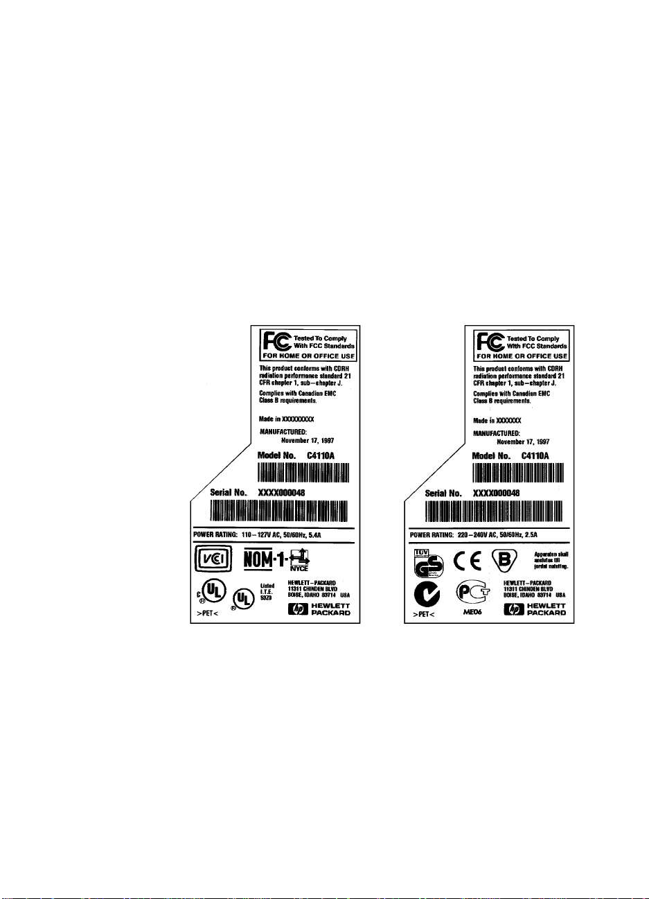
The rear labels also contain power rating and regulatory information
as shown in Figure 1-1.
Figure 1-1
EN
Sample Labels
Identification
1-5
Page 15

Site Requirements
The following environmental specifications must be maintained to
ensure the proper operation of the printer. Consider the following
points before installing the printer:
●
Install in a well-ventilated, dust-free area.
●
Install on a hard, flat and continuous surface, with all four printer
feet level. Do not install on carpet or other soft surfaces.
●
Ensure adequate power is supplied. Printer power requirements
are listed in Table 1-3.
●
Install where temperature and humidity is stable, aw a y from water
sources, humidifiers, air conditioners, refrigerators, or other major
appliances.
●
Install away from direct sunlight, open flames, or ammonia fumes.
If the printer is placed near a window, make sure the window has
a curtain or blind to block any direct sunlight.
●
Install with enough space around the printer for proper access
and ventilation.
●
Install printer away from the direct flow of exhaust from air
ventilation systems.
Table 1-3. Electrical Specifications
Volts Frequency Amps Watts (typical)
100-127 VAC±10% 50/60 Hz ±3Hz 11 amps printing = 365
standby = 40
PowerSave On = 27 (EPA
NERGY STAR
E
220-240 VAC±10% 50/60 Hz ±3Hz 5 amps printing = 355
standby = 40
PowerSave On = 22 (EPA
NERGY STAR
E
®)
®)
1-6 Printer Description
EN
Page 16
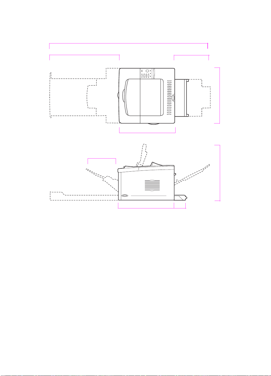
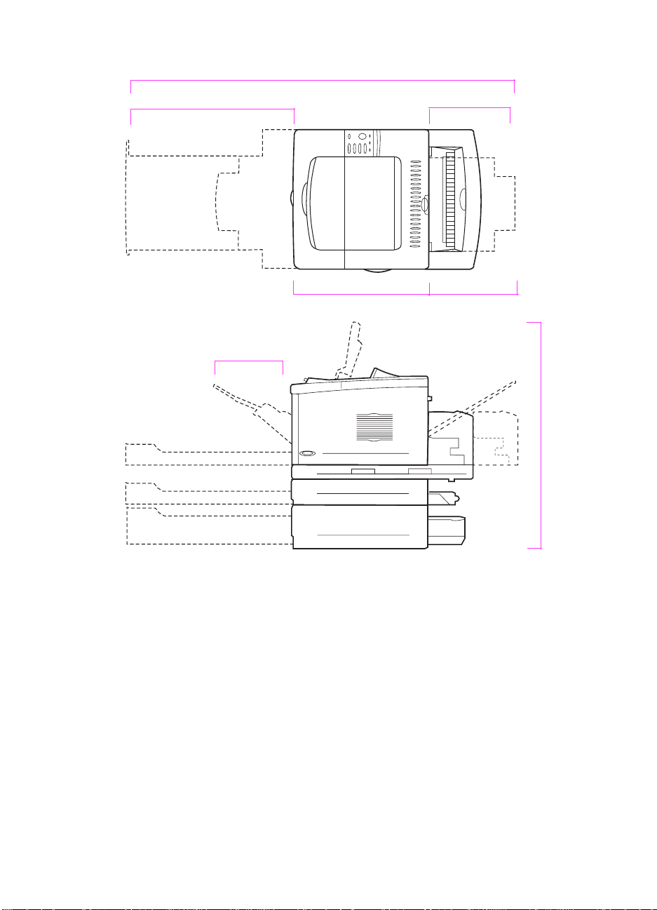
Space Requirements
55 in (139.8 cm)
18.5 in (47.0 cm)
10.6 in (27.0 cm)
11.9 in (30.3 cm)24.6 in (62.5 cm)
18.7 in (47.5 cm) 18.6 in (47.3 cm)
Figure 1-2
EN
18.5 in (47.0 cm)
Printer Dimensions, HP LaserJet 5000
4.3 in (11.0 cm)
Site Requirements
1-7
Page 17
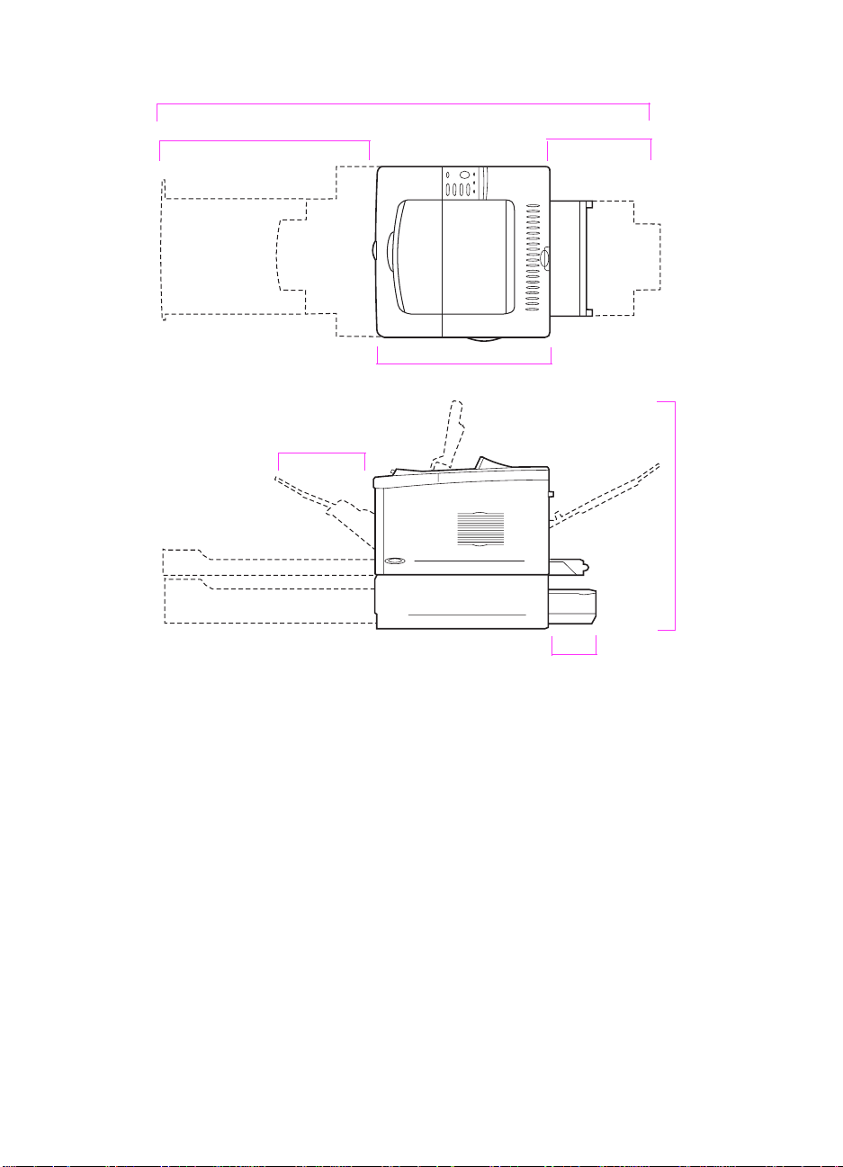
55 in (139.8 cm)
24.6 in (62.5 cm)
10.6 in (27.0 cm)
11.9 in (30.3 cm)
18.5 in (47.0 cm)
24.4 in (62.0 cm)
6.1 in (15.5 cm)
Figure 1-3 Printer Dimensions, HP LaserJet 5000 N/5000 GN
1-8 Printer Description
EN
Page 18
55 in (139.8 cm)
24.6 in (62.5 cm)
10.6 in (27.0 cm)
18.5 in (47.0 cm)
11.9 in (30.3 cm)
6.5 in (16.6 cm)
29.7 in (75.5 cm)
Figure 1-4
EN
Printer Dimensions, HP LaserJet 5000 with Accessories
Printer Weight (without toner cartridge)
HP LaserJet 5000 printer: 50 lb (23 kg)
●
HP LaserJet 5000 N/5000 GN printers: 75 lb (34 kg)
●
HP LaserJet 5000 N/5000 GN printers with duplexer and optional
●
250-sheet feeder: 114 lb (52 kg)
Site Requirements
1-9
Page 19

Environmental Requirements
Table 1-4. Printer and Toner Cartridge Environmental Conditions
Item Operating Storage
Temperature
Relative Humidity 20-80% RH (with no
°
50-91
F (10-32° C)
condensation)
Table 1-5. Acoustic Emissions (Per ISO 9296)
Printer State Sound Power
Printing, 16 pages per
minute (ppm)
Printing, 8 ppm L
PowerSave L
L
= 6.6 bels (A)
wad
= 6.3 bels (A)
wad
= 4.4 bels (A)
wad
-4 to 140°F (-20 to 60°C)
10% TO 95% RH
1-10 Printer Description
EN
Page 20

Paper Specifications
The following tables show paper specifications for the printer.
Table 1-6. Paper Specifications, Tray 1
Supported
Dimensions
1
Weight Capacity
2
Paper
Minimum Size
(custom)
Maximum Size
(custom)
Transparencies
Labels Thickness:
Envelopes 20 to 28 lb
3 by 5 in
(76 by 127 mm)
12.28 by 18.5 in
(312 by 470 mm)
Same as minimum
and maximum paper
sizes listed above.
16 to 53 lb
(60 to 199 g/m
Thickness:
0.0039 in to 0.0045 in
(0.099 to 0.114 mm)
0.005 in to 0.007 in
(0.127 mm to
0.178 mm)
(75 to 105 g/m
2
)
2
)
100 sheets of 20 lb
(75 g m2) paper
75 transparencies
50 labels
10 envelopes
1. The printer supports a wide range of paper sizes. Check the printer software
for supported sizes. To print custom-size paper see the User’s Guide.
2. Capacity may vary depending on paper weight and thickness, and environmental conditions.
EN
Paper Specifications
1-11
Page 21
Table 1-7. Paper Specifications, Tray 2 or Optional 250-sheet Tray
Supported
Dimensions
Paper
Letter 8.5 by 11 in
(216 by 279 mm)
A4 8.3 by 11.7 in
(210 by 297 mm)
Executive 7.3 by 10.5 in
(191 by 267 mm)
Legal 8.5 by 14 in
(216 by 356 mm)
B5 (JIS) 7.2 by 10 in
(182 by 257 mm)
A5 5.8 by 8.2 in
(148 by 210 mm)
11 x 17 11 by 17 in
(279 by 432 mm)
A3 11.7 by 16.5 in
(297 by 420 mm)
B4 (JIS) 10.1 by 14.3 in
(257 by 364 mm)
1
Weight Capacity
16 to 28 lb
(60 to 105 g/m
2
)
50-100 transparencies
2
250 sheets of 20 lb
(75 g/m
2
) paper
1. The printer supports a wide range of media sizes. Check the printer software
for supported sizes.
2. Capacity may vary depending on media weight and thickness, and environmental conditions.
1-12 Printer Description
EN
Page 22

Table 1-8. Paper Specifications, Optional 500-sheet Tray
Supported
Dimensions
Paper
Letter
Letter-R
A4
A4-R
Executive 7.3 by 10.5 in
Legal 8.5 by 14 in
B5 (JIS) 7.2 by 10 in
A5 5.8 by 8.2 in
11 by 17 11 by 17 in
A3 11.7 by 16.5 in
B4 (JIS) 10.1 by 14.3 in
Custom
3
3
4
8.5 by 11 in
(216 by 279 mm)
8.3 by 11.7 in
(210 by 297 mm)
(191 by 267 mm)
(216 by 356 mm)
(182 by 257 mm)
(148 by 210 mm)
(279 by 432 mm)
(297 by 420 mm)
(257 by 364 mm)
5.8 by 8.2 to
11.7 by 17 in
(148 by 210 to
297 by 432 mm)
1
Weight Capacity
16 to 28 lb
(60 to 105 g/m
2
)
50-100 transparencies
2
500 sheets of 20 lb
(75 g/m
2
) paper
1. The printer supports a wide range of media sizes. Check the printer software
for supported sizes.
2. Capacity may vary depending on media weight and thickness, and environmental conditions.
3. To print rotated paper see the User’s Guide.
4. To print custom-size paper see the User’s Guide.
EN
Paper Specifications
1-13
Page 23

Table 1-9. Paper Specifications, Optional Duplex Printing Accessory (Duplexer)
Dimensions
1
Weight
Minimum 5.8 by 8.3 inches
(148 by 210 mm)
Maximum 11.7 by 17 inches
16 to 28 lb
(60 to 105 g/m
2
)
(297 by 432 mm)
1. The printer supports a wide range of media sizes. Check the printer software
for supported sizes.
Supported Types of Paper
The printer supports the following types of paper:
●
plain
●
letterhead
●
prepunched
●
bond
●
color
●
rough
●
preprinted
●
transparency
●
labels
●
recycled
●
card stock
●
user-defined (5 types)
●
vellum
1-14 Printer Description
EN
Page 24

Guidelines for Using Paper
For best results, use con ventional 20 lb (75 g/m2) paper. Make sure
the paper is of good quality and free of cuts, nicks, tears, spots , loose
particles, dust, wrinkles, voids, and curled or bent edges.
Some paper causes print quality problems, jamming, or damage to
the printer.
For more specific information, see “Image Defects” on page 7-50.
Table 1-10. Guidelines for Using Paper
Symptom Problem with Paper Solution
Poor print quality or toner
adhesion.
Problems with feeding.
Dropouts, jamming, curl. Stored improperly . Store paper flat in its moisture-
Increased gray background
shading.
Excessive curl.
Problems with feeding.
Jamming, damage to printer. Cutouts or perforations. Do not use paper with cutouts
Problems with feeding. Ragged edges. Use quality paper.
Too moist, too rough, too
smooth, or embossed; faulty
paper lot.
Too heavy. Use lighter paper.
Too moist, wrong grain
direction or short-grain
construction.
Try another kind of paper,
between 100-250 Sheffield, 46% moisture content.
proof wrapping.
Open the rear output bin.
Open the rear output bin.
Use long-grain paper.
Set
PAPER REFORMING=ON
FUSER MODE=LOW
Set
or perforations.
.
.
EN
Paper Specifications
1-15
Page 25

Note Do not use letterhead paper that is printed with low-temperature inks,
such as those used in some types of thermography.
Do not use raised letterhead.
The printer uses heat and pressure to fuse toner to the paper. Make
sure that any colored paper or preprinted forms use inks that are
compatible with the printer’s temperature (392° F or 200° C for
0.1 second).
1-16 Printer Description
EN
Page 26
Paper Weight Equivalence Table
Use this table to determine approximate equivalent points in weight
specifications other than U.S. bond w eight. For e xample, to determine
the equivalent of 20 lb U.S. bond weight paper in U.S. cover weight,
locate the bond weight (in row 3, second column) and scan across the
row to the cover w eight (in the fourth column). The equivalent is 28 lb.
Shaded areas indicate a standard weight for that grade.
Table 1-11. Paper Weight Equivalence
U.S.
Post
Card1
thick-
ness
(mm)
U.S.
Bond
Weight
(lb)
U.S.
Text/
Book
Weight
(lb)
U.S.
Cover
Weight
(lb)
U.S.
Bristol
Weight
(lb)
U.S.
Index
Weight
(lb)
U.S. Tag
Weight
(lb)
Europe
Metric
Weight
(g/m2)
Japan
Metric
Weight
(g/m2)
1 16 41 22 27 33 37 60 60
2 17432429353964
3
4 215430364449
20 50 28 34 42 46 75 75
80 80
5 22563138465181
6
7 276837455561
8
9
24 60 33 41 50 55 90 90
100 100
28 70 39 49 58 65 105 105
32 80 44 55 67 74 120 120
10 34 86 47 58 71 79 128
11
12
.18 39 100 55 67 82 91 148 148
36 90 50 62 75 83 135 135
13 .19 42 107 58 72 87 97 157
64
81
128
157
14
15 .23 47 119
16 53 134 74 90
.20 43 110 60 74 90 100 163 163
65 80 97 108 176 176
110 122 199 199
1. U.S. Post Card measurements are approximate. Use for reference only.
EN
Paper Specifications
1-17
Page 27

Labels
CAUTION To avoid damaging the printer, use only labels recommended for use
in laser printers.
If you have problems printing labels, use T ray 1 and open the rear output
bin.
Never print on the same sheet of labels more than once.
Label Construction
When selecting labels, consider the quality of each component:
●
Adhesives: The adhesive material should be stable at 392° F
(200° C), the printer’s maximum temperature.
●
Arrangement: Only use labels with no exposed backing between
them. Labels can peel off of sheets that have spaces between the
labels, causing serious jams.
●
Curl: Prior to printing, labels must lie flat with no more than 0.5 in
(13 mm) of curl in any direction.
●
Condition: Do not use labels with wrinkles, bubbles, or other
indications of separation.
Transparencies
Transparencies used in the printer must be able to withstand 392° F
(200° C), the printer’s maximum temperature. For best results, close
the rear output bin to print transparencies to the top output bin.
CAUTION T o a void damaging the printer , use only transparencies recommended
for use in laser printers.
If you have problems printing transparencies, use Tray 1.
Vellum
Vellum is special lightweight paper similar to parchment. Print vellum
from Tray 1 only, and open the rear output bin. Do not print on both
sides of vellum.
Vellum used in the printer must be able to withstand 392° F (200° C),
the printer’s maximum temperature.
1-18 Printer Description
EN
Page 28
Envelopes
Envelope Construction
Envelope construction is critical. Envelope fold lines can vary
considerably, not only between manufacturers, but also within a box
from the same manufacturer. Successful printing on envelopes
depends upon the quality of the envelopes. When selecting
envelopes, consider the following components:
●
Weight:
28 lb (105 g/m
●
Construction:
The weight of the envelope paper should not exceed
2
), or jamming may result.
Prior to printing, envelopes should lie flat with less
than 0.25 in (6 mm) curl, and should not contain air. (Envelopes
that trap air may cause problems.)
●
Condition:
Make sure envelopes are not wrinkled, nicked, or
otherwise damaged.
●
Sizes in Tray 1:
From 3 by 5 in (76 by 127 mm) to 12.28 by 18.5
in (312 by 470 mm).
Always print envelopes from Tray 1. To prevent envelopes from
wrinkling or jamming, open the rear output bin.
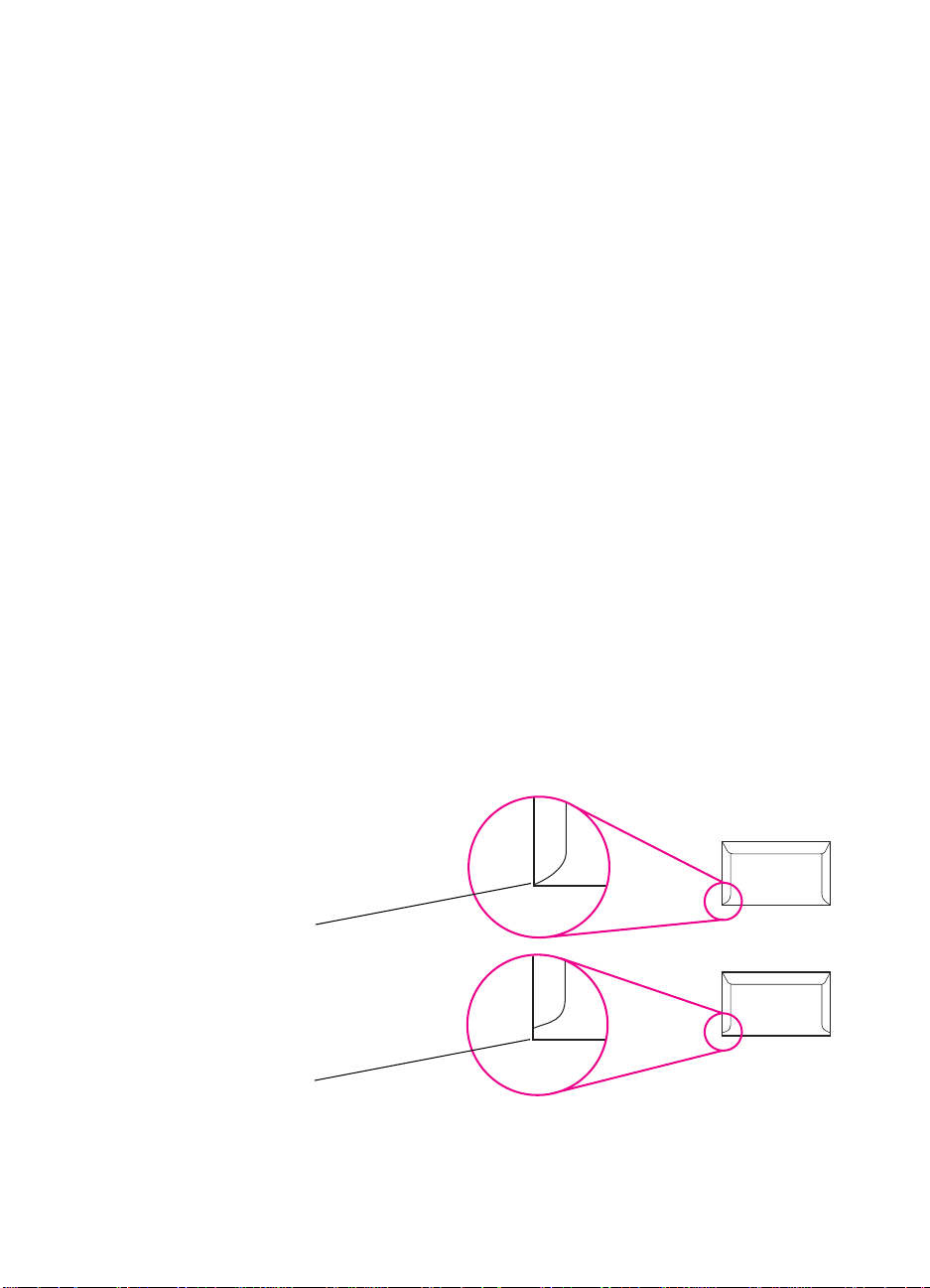
Envelopes with Double-Side-Seams
Double-side-seam construction has vertical seams at both ends of
the envelope rather than diagonal seams. This style may be more
likely to wrinkle. Be sure the seam extends all the wa y to the corner of
the envelope as illustrated below.
Figure 1-5
EN
Acceptable
Unacceptable
Envelopes with Double-Side-Seams
Paper Specifications
1-19
Page 29

Envelopes with Adhesive Strips or Flaps
Envelopes with a peel-off adhesive strip or with more than one flap
that folds over to seal must use adhesives compatible with the heat
and pressure in the printer. The extra flaps and strips might cause
wrinkling, creasing, or jams.
Envelope Margins
The following table gives typical address margins for a Commercial
#10 or DL envelope.
Table 1-12. Envelope Margins
Type of Address Top Margin Left Margin
Return Address 0.6 in (15 mm) 0.6 in (15 mm)
Delivery Address 2 in (51 mm) 3.5 in (89 mm)
Note For the best print quality , position margins no closer than 0.6 in (15 mm)
from the edges of the envelope.
Envelope Storage
Proper storage of envelopes helps contribute to good print quality.
Envelopes should be stored flat. If air is trapped in an envelope,
creating an air bubble, the envelope may wrinkle during printing.
Card Stock and Heavy Paper
Many types of card stock can be printed from Tray 1, including index
cards and postcards. Some card stock performs better than others
because its construction is better suited for feeding through a laser
printer.
For optimum printer performance, do not use paper hea vier than 53 lb
(199 g/m
too heavy might cause misfeeds , stacking problems , paper jams, poor
toner fusing, poor print quality, or excessive mechanical wear.
Note Printing on heavier paper may be possible if the tray is not filled to
capacity, and paper with a smoothness rating of 100-180 Sheffield is
used.
1-20 Printer Description
2
) in Tray 1 or 28 lb (105 g/m2) in other trays. Paper that is
EN
Page 30

Card Stock Construction
2
●
Smoothness:
36-53 lb (135-199 g/m
smoothness rating of 100-180 Sheffield. 16-36 lb (60-135 g/m
card stock should have a smoothness r ating of 100-250 Sheffield.
●
Construction:
Card stock should lie flat with less than 0.2 in
(5 mm) of curl.
●
Condition:
Make sure card stock is not wrinkled, nicked, or
otherwise damaged.
●
Use only card stock within the following size ranges:
Sizes:
• minimum: 3 by 5 in (76 by 127 mm)
• maximum: 12.28 by 18.5 in (312 by 470 mm)
) card stock should have a
2
)
Note
Before loading card stock in Tray 1, make sure it is regular in shape
and not damaged. Also, make sure the cards are not stuck together.
Card Stock Guidelines
If cards curl or jam, try printing from Tray 1 and opening the rear
●
output bin.
Set margins at least 0.08 in (2 mm) away from the edges of the
●
paper.
EN
Paper Specifications
1-21
Page 31

Safety Information
Laser Safety Statement
The Center for Devices and Radiological Health (CDRH) of the U.S.
Food and Drug Administration has implemented regulations for laser
products manufactured since August 1, 1976. Compliance is
mandatory for products marketed in the United States. The printer is
certified as a “Class 1” laser product under the U.S. Department of
Health and Human Services (DHHS) Radiation Performance
Standard according to the Radiation Control for Health and Safety Act
of 1968. Since radiation emitted inside the printer is completely
confined within protective housings and external covers, the laser
beam cannot escape during any phase of normal user operation.
WARNING! Using controls, making adjustments, or performing procedures other
than those specified in this service manual may result in exposure to
hazardous radiation.
Canadian DOC Regulations
Complies with Canadian EMC Class B requirements.
<<Conforme á la classe B des normes canadiennes de compatibilité
électromagnétiques. << CEM>>.>>
1-22 Printer Description
EN
Page 32

FCC Regulations
This equipment has been tested and found to comply with the limits
for a Class B digital device, pursuant to Part 15 of the FCC rules.
These limits are designed to provide reasonable protection against
harmful interference in a residential installation. This equipment
generates, uses, and can radiate radio frequency energy. If this
equipment is not installed and used in accordance with the
instructions, it may cause harmful interference to radio
communications. Howe ver, there is no guarantee that interference will
not occur in a particular installation. If this equipment does cause
harmful interference to radio or television reception, which can be
determined by turning the equipment off and on, the user is
encouraged to try to correct the interference by one or more of the
following measures:
Reorient or relocate the receiving antenna.
●
Increase separation between equipment and receiver.
●
Connect equipment to an outlet on a circuit different from that to
●
which the receiver is located.
Consult your dealer or an experienced radio/TV technician.
●
Note
Any changes or modifications to the printer that are not expressly
approved by HP could void the user’s authority to operate this
equipment.
Use of a shielded interface cable is required to comply with the Class B
limits of Part 15 of FCC rules.
EN
Safety Information
1-23
Page 33

Laser statement for Finland
Luokan 1 laserlaite
Klass 1 Laser Apparat
HP LaserJet 5000, 5000 N, 5000 GN -laserkirjoitin on käyttäjän
kannalta turvallinen luokan 1 laserlaite. Normaalissa käytössä
kirjoittimen suojakotelointi estää lasersäteen pääsyn laitteen
ulkopuolelle. Laitteen turvallisuusluokka on määritetty standardin EN
60825-1 (1994) mukaisesti.
Varoitus!
Laitteen käyttäminen muulla kuin käyttöohjeessa mainitulla tavalla
saattaa altistaa käyttäjän turvallisuusluokan 1 ylittävälle
näkymättömälle lasersäteilylle.
Varning!
Om apparaten används på annat sätt än i bruksanvisning
specificerats, kan användaren utsättas för osynlig laserstrålning, som
överskrider gränsen för laserklass 1.
HUOLTO
HP LaserJet 5000, 5000 N, 5000 GN -kirjoittimen sisällä ei ole
käyttäjän huollettavissa olevia kohteita. Laitteen saa avata ja huoltaa
ainoastaan sen huoltamiseen koulutettu henkilö. Tällaiseksi
huoltotoimenpiteeksi ei katsota väriainekasetin vaihtamista,
paperiradan puhdistusta tai muita käyttäjän käsikirjassa lueteltuja,
käyttäjän tehtäväksi tarkoitettuja ylläpitotoimia, jotka voidaan
suorittaa ilman erikoistyökaluja.
Varo!
Mikäli kirjoittimen suojakotelo avataan, olet alttiina näkymättömälle
lasersäteilylle laitteen ollessa toiminnassa. Älä katso säteeseen.
1-24 Printer Description
EN
Page 34

V arning!
Om laserprinterns skyddshölje öppnas då apparaten är i funktion,
utsättas användaren för osynlig laserstrålning. Betrakta ej strålen.
Tiedot laitteessa käytettävän laserdiodin säteilyominaisuuksista:
Aallonpituus 775-795 nm
Teho 5 mW
Luokan 3B laser
Material Safety Data Sheet
The Toner Cartridge/Drum MSDS can be obtained by calling the U.S.
HP FIRST (Fax Information Retrieval Support Technology) at (1)
(800) 231-9300. Use Index number 7 for a listing of the Toner
Cartridge/Drum Material/Chemical Safety Data Sheets. Non-U.S.
customers should refer to the support section of the User’s Guide for
appropriate phone numbers and information.
EN
Safety Information
1-25
Page 35

Environmental Product Stewardship
Protecting the Environment
Hewlett-Packard Company is committed to providing quality products
in an environmentally-sound manner. The printer has been designed
to minimize impacts on the environment.
The printer design eliminates:
Ozone
Production
Energy
Consumption
The printer does not use high-voltage corona wires in the
electrophotographic process and therefore generates no
appreciable ozone gas (O3). Instead, this printer uses charging
rollers in the toner cartridge and in the print engine.
This HP LaserJet printer design reduces:
Energy usage drops to as little as 21 W while in low-power
(Po werSave) mode. Not only does this save natural resources, but
it also saves money without affecting the high performance of this
printer. This product qualifies for the E
and Japan). E
NERGYSTAR
is a voluntary program established to
NERGYSTAR
encourage the dev elopment of energy-efficient office products.
E
NERGYSTAR
is a U.S. registered service mark of the U.S. EPA.
As an E
NERGYSTAR
partner, Hewlett-Packard
Company has determined that this product
meets E
efficiency
NERGYSTAR
.
Guidelines for energy
Program (U.S.
1-26 Printer Description
EN
Page 36

2
Service Approach
Overview
This chapter discusses the following:
Service Approach
●
Parts and Supplies
●
Warranty Statement
●
EN
Overview
2-1
Page 37

Service Approach
Repair of the printer normally begins with use of the printer’s internal
diagnostics in conjunction with the troubleshooting procedures in
Chapter 7. Once a faulty part is located, repair is generally
accomplished by assembly level replacement of Field Replaceable
Units (FRUs). Some mechanical assemblies may be repaired at the
subassembly lev el. PCA component replacement is not supported by
Hewlett-Packard.
2-2 Service Approach
EN
Page 38

Parts and Supplies
Ordering Information
Field replaceable and accessory part numbers are found in Chapter 8
of this manual. Replacement parts may be ordered from HP’s Support
Materials Organization (SMO) or Support Materials Europe (SME).
Use only accessories specifically designed for this printer.
Accessories can be ordered from an authorized service or support
provider. See page 2-5 and page 8-4 for more information.
EN
Parts and Supplies
2-3
Page 39

Helpful Documentation
Table 2-1 lists part numbers to order documentation.
Table 2-1. Helpful Documentation
Item Description or Use Part Number
HP LaserJet Printer Family
Paper Specification Guide
PCL 5/PJL Technical
Reference Documentation
Package
HP LaserJet 5000, 5000 N,
and 5000 GN Printers User’s
Guide
HP LaserJet 5000, 5000 N,
and 5000 GN Printers Getting
Started Guide
HP LaserJet 5000, 5000 N,
and 5000 GN Printers Quick
Reference Guide
User’s Documentation
Bundle, HP LaserJet 5000,
5000 N, and 5000 GN
A guide to using paper and
other print media with
HP LaserJet printers.
A guide to using printer
commands with HP LaserJet
printers.
An additional copy of the
user’s guide.
An additional copy of the
getting started guide.
An additional copy of the quick
reference guide.
An additional copy of the
user’s guide, the getting
started guide, and the quick
reference guide.
5021-8909
5021-0330
C4110-90901 (English)
C4110-90926 (English)
C4110-90976 (English)
C4110-99001 (English)
2-4 Service Approach
EN
Page 40

Phone Numbers for Ordering
SMO (Support Materials Organization)
●
1-800-227-8164 (U.S. only)
SME (Support Materials Europe)
●
(49 7031) 142253
Exchange Program
HP offers remanufactured assemblies for some parts. These are
identified in Chapter 8 and can be ordered through Support Materials
Organization (SMO), or Support Materials Europe (SME).
Consumables
Paper and Toner Cartridges can be ordered directly from HewlettPackard. See Chapter 8 for ordering information.
Technical Assistance
HP ASAP (Automated Support Access Program) provides free
technical support information 24 hours a day, 7 days a week. The
ASAP system includes HP AUDIO-TIPS and HP FIRST, both
explained below . The ASAP service 1-800-333-1917 (U .S.) requires a
touchtone phone.
EN
To order additional printer drivers for software applications, call HP’s
Distribution Center (HPD) 1-970-339-7009.
HP AUDIO-TIPS
HP AUDIO-TIPS is an interactive voice response system providing
prerecorded answers to the questions asked most frequently by
HP LaserJet printer users. Helpful “System Maps” to the HP AUDIOTIPS recordings are available by fax through HP FIRST.
Parts and Supplies
2-5
Page 41

HP FIRST
HP FIRST (Fax Information Retrieval Support Technology) is a
phone-in fax service that provides technical information for
HP LaserJet users as well as service personnel. Receiving a fax
requires a group 3 facsimile machine or fax card. Service related
information includes:
●
Service notes (HP Authorized dealers)
●
Application notes
●
Product Data Sheets
●
Material Safety Data Sheets (MSDS)
●
Typeface and accessory information
●
Printer support software information
●
Toner information
●
Driver request form and Software Matrix
HP FIRST, U.S.
Call the HP ASAP system (1-800-333-1917) and follow the voice
prompts to enter HP FIRST.
HP FIRST, Europe
Call HP FIRST at one of the following numbers:
U.K., 0800-96-02-71
Belgium (Dutch), 078-111906
Switzerland (German), 155-1527
Netherlands, 06-0222420
Germany, 0130-810061
Austria, 0660-8128
For English service outside the above countries,
call (31) 20-681-5792.
HP CompuServe Forum
CompuServe™ members can download a variety of support
materials including product data sheets, software application notes,
and printer drivers for many popular software applications. Members
may also post and reply to questions in an interactive format. To
access the HP Forum, type GO HP at any prompt. For more
information, or to join CompuServe, call 1-800-524-3388.
2-6 Service Approach
EN
Page 42

North American Response Center (NARC)
The North American Response Center (NARC) is available to assist
service technicians. The NARC can be reached at 1-800-544-9976.
Other Areas
Outside of North America and Europe, contact your local HP sales
office for assistance in obtaining technical support.
EN
Parts and Supplies
2-7
Page 43

Toner Cartridge Information
The Toner Cartridge is designed to simplify replacement of the major
“consumable” parts. The Toner Cartridge contains the printing
mechanism and a supply of toner.
At 5% page coverage, a Toner Cartridge will print approximately
10,000 pages. Howe v er, a T oner Cartridge should print more pages if
regularly printing pages with less coverage, such as short memos.
The cartridge may print fewer pages if routinely printing dense print.
Note For best results, always use a Toner Cartridge before the expiration
date stamped on the Toner Cartridge’s box.
Refilled Toner Cartridges
While Hewlett-Packard does not prohibit the use of refilled Toner
Cartridges during the warranty period or while the printer is under a
maintenance contract, it is not recommended for the following
reasons:
●
Repairs resulting from the use of refilled Toner Cartridges are not
covered under Hewlett-Packard warranty or maintenance
contracts.
●
Hewlett-Packard has no control or process to ensure that a
refilled Toner Cartridge functions at the high level of reliability of a
new HP LaserJet Toner Cartridge. Hewlett-Packard also cannot
predict what the long term reliability effect on the printer is from
using different toner formulations found in refilled cartridges.
●
The print quality of HP LaserJet Toner Cartridges influences the
customer’s perception of the printer. Hewlett-Packard has no
control over the actual print quality of a refilled Toner Cartridge.
Recycling Toner Cartridges
In order to reduce waste, Hewlett-Packard offers a recycling program
for used Toner Cartridges. Cartridge components that do not wear out
are recycled. Plastics and other materials are recycled. HP pays the
shipping costs from the user to the recycling plant. To join this
recycling effort, follow the instructions inside the Toner Cartridge’s
box.
2-8 Service Approach
EN
Page 44

Warranty Statement
This warranty gives specific legal rights. There may also be other
rights which vary from area to area. Refer to the User’s Guide for
further warranty information, or see the warranty card included with
the printer.
EN
Warranty Statement
2-9
Page 45

2-10 Service Approach
EN
Page 46

3
Printer Operation
Overview
This chapter discusses the following:
Using the Control Panel
●
Control Panel Menus
●
Service Mode
●
Testing the Printer
●
Resetting the Printer
●
System Configuration
●
Printer I/O Configuration
●
EN
Overview
3-1
Page 47

Using the Control Panel
Ready Data Attention
Go
Cancel
Job
Menu
Item
- Value +
Select
2-line
display
READY
Control Panel Layout
The printer’s Control Panel consists of the following:
Figure 3-1 Control Panel Layout
Control Panel Lights
Table 3-1. Control Panel Lights
Light Indication
Ready The printer is ready to print.
Data The printer is processing information.
Attention Action is required. See the Control Panel display.
3-2 Printer Operation
EN
Page 48

Control Panel Keys
Table 3-2. Control Panel Keys
Key Function
●
[Go]
Places the printer either online or offline.
●
Prints any data residing in the printer’s buffer.
●
Allows the printer to resume printing after being offline.
●
Clears most printer messages and places the printer online.
●
Allows the printer to continue printing with an error message
such as
PAPER SIZE
●
Confirms a manual feed request if Tray 1 is loaded and
TRAY 1 MODE=CASSETTE
Handling Menu in the printer’s Control Panel.
●
Overrides a manual feed request from Tray 1 by selecting
paper from the next available tray.
●
Exits the Control Panel menus. (To save a selected Control
Panel setting, first press
TRAY x LOAD [TY PE] [SIZE] or UNEXPECTED
.
has been set from the Paper
[Select]
.)
[Cancel Job]
[Menu]
[Item]
[- Value +]
[Select]
Cancels the print job that the printer is processing. The time it
takes to cancel depends on the size of the print job. (Press it only
once.)
Cycles through the Control Panel menus. Press the right end of
the button to move forward or the left end of the button to move
backward.
Cycles through the selected menu’s items. Press the right end of
the button to move forward or the left end of the button to move
backward.
Cycles through the selected menu item’s values. Press
move forward or
●
Saves the selected value f or that item. An asterisk (*) appears
next to the selection, indicating that it is the new default.
Default settings remain when the printer is switched off or
reset (unless you reset all factory defaults from the Resets
Menu).
●
Prints one of the printer information pages from the Control
Panel.
[-]
to move backward.
[+]
to
EN
Using the Control Panel
3-3
Page 49

Settings and Defaults
The printer makes most printing decisions based on either temporary
settings or permanent defaults.
Note Settings sent from software applications override printer defaults.
Table 3-3. Settings and Defaults
Setting or Default Explanation
Temporary Setting A value set for the current print job by the software application.
For example, a request from the software to print three copies
instead of the Control Panel default value of one copy is a
temporary setting. The printer continues to use the temporary
setting until it receives another software request or until it is reset.
Control Panel Default A value set at the Control Panel when you select a menu item. An
asterisk appears, indicating the default setting. The printer retains
this default when it is turned off.
Factory Default The value set for each menu item at the factory. Factory defaults
are listed in the item column in the menu tables starting on page
3-6.
Setting the Display Language
1 Press and hold [Select] while turning on the printer. Hold [Select]
until SELECT LA NGUAGE appears.
2 Release [Select]. INITIALIZING appears briefly. Wait for
LANGUAGE=ENGLISH to appear.
3 Press [- Value +] repeatedly until the desired language appears.
4 Press [Select] to save your choice. An asterisk (*) will appear
beside the selected language.
5 Press [Go] to exit menu.
3-4 Printer Operation
EN
Page 50

Control Panel Menus
Press [Menu] for access to all Control Panel menus. When additional
trays or other accessories are installed in the printer, ne w menu items
automatically appear.
To change a Control Panel setting:
Press [Menu] until the desired menu appears.
1
Press [Item] until the desired item appears.
2
Press [- Value +] until the desired setting appears.
3
Press [Select] to save the selection. An asterisk (*) appears next
4
to the selection in the display, indicating that it is now the default.
Press [Go] to exit the menu.
5
Note
Settings in the printer driver and software application override Control
Panel settings. (Software application settings override printer driver
settings.)
If you cannot access a menu or item, it is either not an option for the
printer, or the customer’ s network administrator has locked the function.
(The Control Panel reads ACCESS DENIE D MENUS LOCKE D.) See the
customer’s network administrator.
To print a Control Panel menu map:
To see the current settings for all of the menus and items available in
the Control Panel, print a Control Panel menu map.
Press [Menu] until INFORMATION MENU appears.
1
Press [Item] until PRINT MENU MA P appears.
2
Press [Select] to print the menu map.
3
EN
Control Panel Menus
3-5
Page 51

Information Menu
This menu contains printer information pages that give details about
the printer and its configuration. To print an information page, scroll to
the desired page and press [Select].
Table 3-4. Information Menu
Item Explanation
PRINT
MENU MAP
PRINT CONFIGURA TION
PRINT
PCL FONT LIST
PRINT
PS FONT LIST
PRINT
FILE DIR ECTORY
PRINT
EVENT LOG
The menu map shows the layout and current settings of the
Control Panel menu items.
The Configuration Page shows the printer’s current configuration.
If an HP JetDirect print server card is installed (HP LaserJet
5000 N/5000 GN printers), a JetDirect Configuration Page will
print out as well.
The PCL font list shows all the PCL fonts currently a v ailable to the
printer.
The PS font list shows all the PS fonts currently available to the
printer.
This item appears only when a mass storage device (such as an
optional flash DIMM or hard disk) containing a recognized file
system is installed in the printer. The file directory shows
information for all installed mass storage devices.
The event log lists printer events or errors.
SHOW
EVENT LOG
PRINT
PAPER PATH TEST
3-6 Printer Operation
This item allows you to view the most recent printer e v ents on the
Control Panel display. Press
log entries.
The paper path test can be used to verify that the paper path is
working properly, or to troubleshoot problems with a type of
paper.
Choose the input tray, output bin, duplexer (if available), and
number of copies.
[-V alue+]
to scroll through the event
EN
Page 52

Paper Handling Menu
When paper handling settings are correctly configured through the
Control Panel, you can print by choosing the type and size of paper
from the printer driver or software application.
Some items in this menu (such as duplex and manual feed) can be
accessed from a software application, or from the printer driver (if the
appropriate driver is installed). Printer driver and software application
settings override Control Panel settings.
Table 3-5. Paper Handling Menu
Item Values Explanation
TRAY 1 MODE=
FIRST
TRAY 1 SIZE=
LETTER
TRAY 1 TYPE=
PLAIN
TRAY 2 TYPE=
PLAIN
FIRST
CASSETTE
For supported paper types
see page 1-14.
For supported paper types
see page 1-14.
For supported paper types
see page 1-14.
Determine how the printer will use
Tray 1.
FIRST
: If paper is loaded in Tray 1,
the printer will pull paper from that
tray first.
CASSETTE
assigned to Tray 1 using the
TRAY 1 SIZE
in this menu when
MODE=CA SSETTE
Tray 1 to be used as a reserved tray.
This item appears only when
MODE=
correspond with the paper size
currently loaded in Tray 1.
This item appears only when
MODE=
correspond with the paper type
currently loaded in Tray 1.
Set the value to correspond with the
paper type currently loaded in Tray 2.
:
A paper size must be
option (the next item
TRAY 1
). This allows
CASSETTE
CASSETTE
. Set the value to
. Set the value to
TRAY 1
TRAY 1
TRAY 3 TYPE=
PLAIN
EN
For supported paper types
see page 1-14.
This item appears only when a third
paper tray is installed. Set the value
to correspond with the paper type
currently loaded in Tray 3.
Control Panel Menus
3-7
Page 53

Table 3-5. Paper Handling Menu (continued)
Item Values Explanation
TRAY 4 TYPE=
PLAIN
For supported paper types
see page 1-14.
MANUAL FEED=OFF OFF
ON
DUPLEX=OFF OFF
ON
BINDING=
LONG EDGE
LONG EDGE
SHORT EDGE
This item appears only when a fourth
paper tray is installed. Set the value
to correspond with the paper type
currently loaded in Tray 4.
Feed the paper manually from Tray 1,
rather than automatically from a tray.
MANUAL FEED=ON
When
is empty, the printer goes offline
when it receives a print job and
displays
SIZE]
This item appears only when an
optional duplexer is installed. Set the
value to
(duplex) or
(simplex) of a sheet of paper.
This item appears only when an
optional duplexer is installed and the
duplex option is on. Choose the
binding edge when duplexing
(printing on both sides of paper).
MANUALLY FEED [PAPER
.
to print on both sides
ON
to print on one side
OFF
and Tray 1
OVERRIDE A4 WITH
LETTER=NO
3-8 Printer Operation
NO
YES
Choose
paper when an A4 job is sent, but no
A4 size paper is loaded in the printer
(or to print on A4 size paper when a
letter job is sent, but no letter paper
is loaded in the printer).
to print on letter size
YES
EN
Page 54

Table 3-5. Paper Handling Menu (continued)
Item Values Explanation
CONFIGURE FUSE R MODE
MENU=NO
[TYPE ]=
NORMAL
NO
YES
NORMAL
LOW
HIGH
VELLU M
Configure the fuser mode associated
with each paper type. (This is only
necessary if you are experiencing
problems printing on certain paper
types.)
:
The fuser mode menu items are
NO
not accessible.
:
Additional items appear (see
YES
below).
Note
To see the default fuser mode for
each paper type, select
back to the Information Menu, and
print a menu map (page 3-6).
This item appears only when
YES
, scroll
CONFIGURE FUSE R MODE
MENU=YES
to
NORMAL
. Most paper types are set
by default.
ROUGH=HIGH
VELLUM=VE LLUM
For a complete list of supported paper
types, see page 1-14.
EN
Control Panel Menus
3-9
Page 55

Print Quality Menu
Some items in this menu can be accessed from a software
application, or from the printer driver (if the appropriate driver is
installed). Printer driver and software application settings override
Control Panel settings.
Table 3-6. Print Quality Menu
Item Values Explanation
RESOLUTION=
FASTRES 1200
300
600
FASTRE S 1200
PRORE S 1200
Select the resolution from the
following values:
:
300
Produces draft print
quality at the printer’s
maximum speed (16 ppm).
300 dpi (dots per inch) is
recommended for some
bitmapped fonts and graphics,
and for compatibility with the
HP LaserJet III family of
printers.
:
600
Produces high print
quality at the printer’s
maximum speed (16 ppm).
FASTRE S 1200
optimum print quality
(comparable to 1200 dpi) at
the printer’s maximum speed
(16 ppm).
PRORE S 1200
optimum print quality (true
1200 dpi) at half the printer’s
maximum speed (8 ppm).
When the resolution is
changed, any downloaded
resources (such as fonts or
macros) will need to be
downloaded again, unless
they are stored on an optional
hard disk or flash DIMM.
:
Produces
:
Produces
Note
It is best to change the
resolution from the printer
driver or software application.
(Driver and software settings
override Control Panel
settings.)
3-10 Printer Operation
EN
Page 56

Table 3-6. Print Quality Menu (continued)
Item Values Explanation
RET=ME DIUM OFF
LIGHT
MEDIUM
DARK
ECONOMODE =OFF OFF
ON
Use the printer’s Resolution
Enhancement technology
(REt) setting to produce print
with smooth angles, curves,
and edges.
REt does not affect print
quality when the print
resolution is set to
ProRes 1200. All other print
resolutions, including
FastRes 1200, benefit from
REt.
Note
It is best to change the REt
setting from the printer driver
or software application. (Driver
and software settings override
Control Panel settings.)
Turn EconoMode on (to save
toner) or off (for high quality).
EconoMode creates draftquality printing by reducing the
amount of toner on the printed
page by up to 50%.
Caution
HP does not recommend fulltime use of EconoMode. (If
EconoMode is used full-time, it
is possible that the toner
supply will outlast the
mechanical parts in the Toner
Cartridge.)
Note
It is best to turn EconoMode
on or off from the printer driver
or software application. (Driver
and software settings override
Control Panel settings.)
EN
Control Panel Menus
3-11
Page 57

Table 3-6. Print Quality Menu (continued)
Item Values Explanation
TONER D ENSITY=3 1
CREA TE CLEANING PAGE
2
3
4
5
No value to select.
Lighten or darken the print on
the page by changing the
toner density setting. The
settings range from 1 (light) to
5 (dark), but the default setting
of 3 usually produces the best
results.
Use a lower toner density
setting to save toner.
Note
It is best to change the toner
density from the printer driver
or software application. (Driver
and software settings override
Control Panel settings.)
[Select]
Press
cleaning page (for cleaning
excess toner from the paper
path).
In order for the cleaning page
to work properly, print the
page on copier grade paper
(not bond or rough paper).
Follow the instructions on the
cleaning page.
to print a
PROCESS CLEANING PAGE
3-12 Printer Operation
No value to select. This item appears only after a
cleaning page has been
generated (as described
above).
[Select]
Press
cleaning page.
to process the
EN
Page 58

Printing Menu
Some items in this menu can be accessed from a software
application, or from the printer driver (if the appropriate driver is
installed). Printer driver and software application settings override
Control Panel settings.
Table 3-7. Printing Menu
Item Values Explanation
COPIES=1 1 to 999
PAPER=
LETTER
(110 V printers)
and
For supported paper sizes
see page 1-11.
ENVELOPE =
COM10
(110 V printers)
Set the default number of
copies by selecting any
number from 1 to 999. Press
[-Value+]
setting by increments of 1, or
hold down
by increments of 10.
once to change the
[-Value+]
to scroll
Note
It is best to set the number of
copies from the printer driver
or software application. (Driver
and software settings override
Control Panel settings.)
Set the default image size for
paper and envelopes. (The
item name will change from
paper to envelope as you
scroll through the available
sizes.)
Note
The defaults indicated here
are for 110 V printers. The
default paper size for 220 V
A4
printers is
envelope size for 220 V
printers is
. The default
DL
.
CONFIGURE CUSTOM
PAPER =NO
EN
NO
YES
NO:
The custom paper menu
items are not accessible.
YES:
The custom paper menu
items appear (see the next
item).
Control Panel Menus
3-13
Page 59

Table 3-7. Printing Menu (continued)
Item Values Explanation
UNIT OF MEASURE=INCHES
(110 V printers)
or
MILLIMETERS
(220 V printers)
X DIMENSION=
12.28 INCHES
(110 V printers)
or
312 MILLIMETERS
(220 V printers)
Y DIME NSION=
18.50 INCHES
(110 V printers)
or
470 MILLIMETERS
(220 V printers)
ORIENTA TION=
PORTRAIT
INCHES
MILLIMETERS
3.00 to 12.28 INCHES
(110 V printers)
or
76 to 312 MILLIMETER S
(220 V printers)
5.00 to 18.50 INCHES
(110 V printers)
or
127 to 470 MILLIMETERS
(220 V printers)
PORTRAIT
LANDSCAPE
This item appears only when
CONFIGURE CUSTOM
PAPER =YES
measurement for the custom
paper size.
This item appears only when
. Select the unit of
CONFIGURE CUSTOM
PAPER =YES
dimension to be fed into the
printer (short edge).
This item appears only when
. Select the
CONFIGURE CUSTOM
PAPER =YES
dimension (long edge).
Determine the default
orientation of print on the
page.
. Select the other
Note
It is best to set the page
orientation from the printer
driver or software application.
(Driver and software settings
override Control Panel
settings.)
FORM=60 LINES
(110 V printers)
or
64 LINES
(220 V printers)
3-14 Printer Operation
5 to 128
Sets vertical spacing from 5 to
128 lines for default paper
size. Press
change the setting by
increments of 1, or hold down
[-Value+]
increments of 10.
[-Value+]
to scroll by
once to
EN
Page 60

Table 3-7. Printing Menu (continued)
Item Values Explanation
PCL FONT
SOURCE=INTE RNAL
PCL FONT
NUMBER=0
PCL FONT
PITCH= 10.00
PCL SYMBOL
SET=PC-8
INTERNAL
SOFT
SLOT 1, 2, or 3
0 to 999
0.44 to 99.99
PC-8
many others
INTERNAL
SOFT:
SLOT 1, 2
in one of the three DIMM slots.
The printer assigns a number
to each font and lists them on
the PCL Font List. The font
number appears in the Font #
column of the printout.
This item might not appear,
depending on the font
selected. Press
once to change the setting by
increments of .01 for pitch, or
hold down
by increments of 1.
Select any one of several
available symbol sets from the
printer’s control panel. A
symbol set is a unique grouping
of all the characters in a font.
PC-8 or PC-850 is
recommended for line draw
characters. Order the
PJL Technical Reference
Documentation Package
symbol set charts or for more
information see the user’s
guide.
: Internal fonts.
Permanent soft fonts.
, or 3: Fonts stored
[-Value+]
[-Value+]
to scroll
PCL 5/
for
EN
Control Panel Menus
3-15
Page 61

Table 3-7. Printing Menu (continued)
Item Values Explanation
COURIER=REGULAR REGULAR
DARK
WIDE A4=NO NO
YES
APPEND CR TO LF=
NO
NO
YES
Select the version of Courier
font to use:
REGULA R
font available on the
HP LaserJet 4 series printers.
DARK
available on the HP LaserJet III
series printers.
Both fonts are not available at
the same time.
The Wide A4 setting changes
the number of characters that
can be printed on a single line
of A4 paper.
NO
characters can be printed on
one line.
YES
characters can be printed on
one line.
Select
carriage return to each line feed
encountered in backwardcompatible PCL jobs (pure text,
no job control). Some
environments, such as UNIX,
indicate a new line using only
the line feed control code. This
option allows the user to
append the required carriage
return to each line feed.
: The internal Courier
: The internal Courier font
:
Up to 78 10-pitch
:
Up to 80 10-pitch
YES
to append a
PRINT PS ERRORS=OFF OFF
ON
3-16 Printer Operation
Select ON to print the PS error
page when PS errors occur.
EN
Page 62

Configuration Menu
Items in this menu affect the printer’s behavior. Configure the printer
according to your printing needs.
Table 3-8. Configuration Menu
Item Values Explanation
POWERSAVE=
30 MINUTES
PERSONALITY=
AUTO
OFF
15 MINUTES
30 MINUTES
1 HOUR
2 HOURS
3 HOURS
AUTO
PCL
PS
Set the printer to enter PowerSave after it
has been idle for a specified amount of
time. Turning PowerSave off is not
recommended. The PowerSave feature
does the following:
1. Minimizes the amount of power
consumed by the printer when it is idle.
2. Reduces wear on the printer’s electronic
components. (Turns off the display’s
backlight.)
When you send a print job, press a Control
Panel key, open a paper tray, or open the
top cover, the printer automatically comes
out of PowerSave mode.
Note
PowerSave turns off the backlight on the
display, but the display is still readable.
Select the default printer language
(personality). Possible values are
determined by which valid languages are
installed in the printer.
Normally you should not change the printer
language (the default is
change it to a specific printer language, the
printer will not automatically switch from
one language to another unless specific
software commands are sent to the printer.
AUTO
). If you
EN
Control Panel Menus
3-17
Page 63

Table 3-8. Configuration Menu (continued)
Item Values Explanation
RESOUR CE SAVE =
OFF
OFF
ON
AUTO
(8 MB total is required to
see this message.)
Dedicate printer memory to save each
language’s permanent resources. (You
might need to add memory to the printer in
order for this item to appear.) The amount
of memory set aside can be different for
each installed language. Some languages
might have memory set aside for resource
saving without requiring all languages to do
so. Any time the amount of memory
dedicated to a specific language is
changed, all languages will lose all saved
resources, including any unprocessed print
jobs.
:
OFF
No language resource saving is
performed, and language-dependent
resources, such as fonts and macros, are
lost when language or resolution changes.
:
ON
An item will appear for each installed
language that allows the user to allocate a
particular amount of memory to that
language’s resource saving area. (See the
items below.)
:
AUTO
The printer automatically determines
the amount of memory to use for each
installed language’s resource saving area.
PCL MEMORY=
400K
3-18 Printer Operation
0K
and up
(This value depends on
the amount of installed
memory. 8 MB total is
required to see this
message.)
This item appears only when
SAVE=ON
used for saving PCL resources. Printer
default is the minimum amount of memory
needed to perform resource saving for
PCL.
Press
increments of 10 (up to 100 KB) or by
increments of 100 (above 100 KB).
. Select the amount of memory
[-Value+]
to change settings by
RESOURCE
EN
Page 64

Table 3-8. Configuration Menu (continued)
Item Values Explanation
PS MEMORY=
400K
PAGE PROTECT=
AUTO
CLEARABLE
WARNINGS=JOB
0K
and up
(This value depends on
the amount of installed
memory. 8 MB total is
required to see this
message.)
AUTO
ON
JOB
ON
This item appears only when
SAVE=ON
used for saving PS resources. Printer
default is the minimum amount of memory
needed to perform resource saving for PS.
Press
increments of 10 (up to 100 KB) or by
increments of 100 (above 100 KB).
This item appears only after a
. Select the amount of memory
[-Value+]
to change settings by
RESOURCE
21 PAGE
TOO COMPLEX, PRE SS GO TO CONTINUE
message displays.
Memory Enhancement technology (MEt)
attempts to guarantee that all pages will
print. If the page does not print, turn
PROTECT
chances of a
to ON. This might increase
20 INSUFFICIENT
MEMORY , PRESS GO TO CONTINUE
message. If this occurs, simplify the print
job or install additional memory.
Set the amount of time that a clearable
warning is displayed on the printer’ s Control
Panel.
:
JOB
Warning messages display on the
Control Panel until the end of the job from
which they were generated.
:
ON
Warning messages display on the
Control Panel until
[Go]
is pressed.
PAGE
EN
Control Panel Menus
3-19
Page 65

Table 3-8. Configuration Menu (continued)
Item Values Explanation
AUTO CONTINUE=
ON
TONER
LOW=CONTINUE
ON
OFF
CONTINUE
STOP
Determine how the printer reacts to errors.
:
ON
If an error occurs that prevents printing,
the message will display, and the printer will
go offline for 10 seconds before returning
online.
:
OFF
If an error occurs that prevents
printing, the message will remain on the
display and the printer will remain offline
[Go]
until
If the printer is on a network, you will
probably want to turn
ON
Determine how the printer behaves when
toner is low. The
first appear when the Toner Cartridge is
almost out of toner. (About 100 to 300
sheets can still be printed.)
CONTINUE
while the
displayed.
STOP
further action.
is pressed.
AUTO CONTINUE
.
TONER LOW
:
The printer will continue to print
TONER LOW
:
The printer will go offline and wait for
message is
message will
to
3-20 Printer Operation
EN
Page 66

Table 3-8. Configuration Menu (continued)
Item Values Explanation
MOPIER
MODE=STA NDAR D
STANDA RD
ENHANCED
OFF
Determine how the mopier functions
behave. This item appears only when there
is at least 8 MB of memory or an optional
hard disk is installed.
STANDARD
is either a hard disk installed or a RAM disk
configured in memory. This option uses I/O
data stored in printer memory for
generating multiple original prints. (All
copies will print at the same speed as the
first copy.)
ENHANCED
is a hard disk installed and at least 8 MB of
memory. This option uses engine video
data for printing multiple original prints and
should print all copies after the first at the
printer’s maximum speed.
OFF
printer will not spool any jobs to the hard
disk.)
When the mopier mode is changed, any
downloaded resources (such as fonts or
macros) will need to be downloaded again,
unless they are stored on an optional hard
disk or flash DIMM.
:
This option is available if there
:
This option is available if there
:
Disables the mopier functions. (The
RAM D ISK=OFF OFF
ON
AUTO
EN
Determine how the RAM disk is configured.
This item appears only if there is no
optional hard disk installed and the printer
has at least 8 MB of memory.
:
OFF
The RAM disk is disabled.
:
ON
The RAM disk is enabled. Configure
the amount of memory to be used through
the following item:
RAM DISK SIZE
.
Note
If the setting is changed from
OFF
from
automatically reinitialize when it becomes
idle.
to
AUTO
, the printer will
Control Panel Menus
OFF
to ON or
3-21
Page 67

Table 3-8. Configuration Menu (continued)
Item Values Explanation
RAM D ISK
SIZE=xxxK
JAM RECOVERY=
AUTO
PAPER
REFOR MING=OFF
0K
and up
(This value depends on
the amount of installed
memory.)
AUTO
ON
OFF
OFF
ON
Determine the size of the RAM disk. This
item appears if
[-V alue+]
Press
increments of 100.
RAM DISK=ON
to change settings by
or
AUTO
.
Note
This setting cannot be changed if
DISK=AUTO
the printer to reinitialize when it becomes
idle.
Determine how the printer behaves when a
paper jam occurs.
AUTO
best mode for printer jam recovery (usually
ON
). This is the default setting.
ON
: The printer automatically reprints pages
after a paper jam is cleared.
OFF
: The printer does not reprint pages
following a paper jam. Printing performance
might be increased with this setting.
Paper reforming has two main purposes:
1. To reduce jams, wrinkles, and bent
corners when printing on both sides of a
sheet of paper (duplexing).
2. To reduce bent cor ners and wrinkles
when printing on one side of a sheet of
narrow media (such as legal, rotated letter,
or rotated A4).
Print speed will be slower when
REFOR MING=ON
. Changing this value will cause
: The printer automatically selects the
.
RAM
PAPER
3-22 Printer Operation
EN
Page 68

Table 3-8. Configuration Menu (continued)
Item Values Explanation
MAINTENA NCE
MESSAGE=OFF
SMALL PAPE R
SPEED=NORMAL
OFF
NORMAL
SLOW
This item appears only after the
PRINTER MAINTENANCE
displays.
OFF
MAINTENA NCE
will not be displayed again until the next
maintenance is due.
The message should not be turned off
unless the printer maintenance has been
performed. If the required maintenance is
not performed, the printer’s performance
will degrade.
Select
envelopes or small paper and standard
paper sizes.
Be sure to return the speed to
when finished.
PERFORM PRINTER
: The
message will be cleared and
SLOW
when alternately printing
message
PERFOR M
NORMAL
EN
Control Panel Menus
3-23
Page 69

I/O Menu
Items in the I/O (input/output) Menu affect the communication
between the printer and the computer.
Table 3-9. I/O Menu
Item Values Explanation
I/O TIMEOUT=15 5
to
I/O BUFFER=AUTO AUTO
ON
OFF
300
Select the I/O timeout period in seconds. (I/O
timeout refers to the time, measured in
seconds, that the printer waits before ending a
print job.)
This setting allows you to adjust timeout for best
performance. If data from other ports appear in
the middle of your print job, increase the timeout
value.
[- Value +]
Press
increments of 1, or hold down
scroll by increments of 10.
Allocate memory for I/O buffering.
:
AUTO
The printer automatically reserves
memory for I/O buffering. Additional
configurations are not required and the
I/O BUFFER SIZE
appear.
:
ON
below). Specify the amount of memory to be
used for I/O buffering.
OFF
I/O BUFFER SIZE
The
:
I/O buffering is not performed and the
I/O BUFFER SIZE
When the I/O buffer setting is changed, any
downloaded resources (such as fonts or
macros) will need to be downloaded again,
unless they are stored on an optional hard disk
or flash DIMM.
once to change settings by
[- Value +]
menu item does not
item appears (see
item does not appear.
to
3-24 Printer Operation
EN
Page 70

Table 3-9. I/O Menu (continued)
Item Values Explanation
I/O BUFFER SIZE =
100K
PARALLEL HIGH
SPEED=YES
PARALLEL ADV
FUNCTIONS=ON
10K
and up This item appears only when
Specify the amount of memory for I/O buffering.
The maximum amount of memory available for
I/O buffering is determined by the amount of
memory installed in the printer, the languages
installed in the printer, and by other memory
allocations that must be made.
[-Value +]
YES
NO
ON
OFF
Press
increments of 10 (up to 100 KB) or by
increments of 100 (above 100 KB).
Select the speed at which data is transmitted to
the printer.
:
YES
The printer accepts faster parallel
communications used for connections with
newer computers.
:
NO
The printer accepts slower parallel
communications used for connections with
older computers.
T urn the bidirectional parallel communication on
or off. The default is set for a bidirectional
parallel port (IEEE-1284).
This setting allows the printer to send status
readback messages to the computer. (Turning
on the parallel advanced functions might slow
language switching.)
to change settings by
I/O BUFFER=ON
.
SERIAL PACING=DTR/
DSR
EN
DTR/DSR
XON/XOFF
Select the type of pacing used. Pacing, or
“handshaking” allows the printer to tell the
computer when to send information. The printer
uses XON/XOFF and DTR/DSR signal
protocols rather than ETX/ACK protocol.
DTR/DSR
requires hardware flow control (most personal
computers do).
XON/XOFF
requires software flow control (a UNIX
workstation, for example). The
XON
:
Select this value if your computer
:
Select this value if your computer
SERIAL ROBUST
item appears (see below).
Control Panel Menus
3-25
Page 71

Table 3-9. I/O Menu (continued)
Item Values Explanation
SERIAL ROBUST
XON=ON
SERIAL BAUD
RATE =9600
ON
OFF
300
600
1200
2400
4800
9600
19200
38400
57600
115200
This item appears only when
PACING=XON/XOFF
generating XONs.
:
ON
The printer sends an XON when the printer
is online and when sufficient buffer space is
available. If the host does not receive data
within approximately one second, the printer will
transmit additional XONs at one-second
intervals until the host receives data.
:
OFF
The printer sends one XON when it can
accept more data or when it is online. The
printer does not send XONs every second while
the printer is online and ready for more data.
Select the printer’s baud rate (speed at which
information is transferred) for communicating
from the computer to the printer.
. Select the method for
SERIA L
SERIAL DTR
POLARITY =HIGH
3-26 Printer Operation
HIGH
LOW
Determine whether pin #8 is high or low when
the printer is ready.
:
HIGH
Pin #8 is held high when the printer is
ready.
:
LOW
Pin #8 is held low when the printer is
ready.
EN
Page 72

EIO Menu (Networked Printers)
EIO (Enhanced Input/Output) Menus depend on the particular
accessory product installed in an EIO slot of the printer. If the printer
contains an HP JetDirect print server EIO card, you can configure
basic networking parameters using the EIO Menu. These and other
parameters can also be configured through HP JetAdmin.
Table 3-10. EIO Menu
Item Values Explanation
CFG NETWORK=NO NO
YES
NOVELL=ON ON
OFF
DLC/LLC=ON ON
OFF
TCP/IP=ON ON
OFF
ETALK=ON ON
OFF
CFG NOVELL=NO NO
YES
NO
: The JetDirect Menu is not accessible.
YES
: The JetDirect Menu appears.
Select whether the IPX/SPX protocol stack
(in Novell NetW are networks, for example) is
enabled (on) or disabled (off).
Select whether the DLC/LLC protocol stack
is enabled (on) or disabled (off).
Select whether the TCP/IP protocol stack is
enabled (on) or disabled (off).
Select whether the Apple EtherTalk protocol
stack is enabled (on) or disabled (off).
NO
: The IPX/SPX Menu is not accessible.
YES
: The IPX/SPX Menu appears. In the IPX/
SPX Menu, you can specify the frame type
parameter used on your network. The default
AUTO
is
frame type to the one detected.
For Ethernet cards, frame type selections
include
EN_SNAP
For Token Ring cards, frame type selections
include
In the IPX/SPX Menu for Token Ring cards,
you can also specify NetWare Source
Routing parameters, which include
RT=AUTO
RT
, to automatically set and limit the
EN_8023, EN_II, EN_8022
.
TR_8022, TR_SNAP
(default),
.
OFF, SINGLE R
.
,
SRC
, or
ALL
EN
Control Panel Menus
3-27
Page 73

Table 3-10. EIO Menu (continued)
Item Values Explanation
CFG TCP/IP=NO NO
YES
CFG ETALK=NO NO
YES
NO
: The TCP/IP Menu is not accessible.
YES
: The TCP/IP Menu appears. In the TCP/
IP Menu, you can specify
TCP/IP parameters to be automatically
loaded from a bootp or DHCP server when
the printer is turned on. If you specify
BOOTP=NO
TCP/IP parameters from the Control Panel.
You can manually set each byte of the IP
address (IP), Subnet Mask (SM), Syslog
Server (LG), and Default Gateway (GW).
Also, you can manually set the Timeout time
period.
, you can manually set selected
BOOTP=YES
for
Note
If no IP address is assigned within the first 5
minutes, the HP JetDirect print server card
will assume a default IP address of
192.0.0.192.
NO
: The EtherTalk Menu is not accessible.
YES
: The EtherTalk Menu appears. In the
EtherTalk Menu you can set the AppleTalk
phase parameter (
for your network.
ETALK PHASE=1 or 2
)
3-28 Printer Operation
EN
Page 74

Resets Menu
Use this menu with caution. You can lose buffered page data or
printer configuration settings when you select these items. Only reset
the printer under the following circumstances:
You want to restore the printer’s default settings.
●
Communication between the printer and computer has been
●
interrupted.
You are using both the serial and parallel I/O ports, and one of the
●
ports is having problems.
The items in the Resets Menu will clear all memory in the printer,
while [Cancel Job] clears only the current job.
Table 3-11. Resets Menu
Item Explanation
RESE T MEMORY
RESTOR E FACTORY SETTINGS
RESE T ACTIVE I/O CHA NNEL
RESE T ALL I/O CHANNE LS
This item clears the printer buffer and the active
I/O input buffer, and makes the Control Panel
defaults current.
DATA RECE IVED
The
the Control Panel.
Resetting memory during a print job can result in
data loss.
This item performs a simple reset and restores
most of the factory (default) settings. This item
also clears the input buffer for the active I/O.
DATA RECE IVED
The
the printer’s Control Panel.
This item performs a simple reset and clears the
input and output buffers (f or the active I/Os only).
DATA RECE IVED
The
the printer’s Control Panel.
This item performs a simple reset and clears the
input and output buffers for all I/Os.
message might display on
message might display on
message might display on
EN
Control Panel Menus
3-29
Page 75

Service Mode
Service Mode should be used only by authorized service personnel.
While in Service Mode, you can:
●
Verify and set the page count and serial number. These are
displayed on the Configuration Page.
●
Set the Cold Reset Default. (This sets the factory default paper
size to either Letter or A4).
●
Turn the Diagnostic Functions on or off (for developers only).
●
Clear the event log.
●
Set the interval at which the PERFOR M PRINTER MAINTENA NCE
message appears on the control panel.
To enter Service Mode:
1 Hold down [Select] and [Cancel Job] while turning on the printer.
(If the control panel reads INITIALIZING, the keys were released
too soon.)
2 Press the right side of the [Menu] key, then press [Select]. The
message SERVICE MODE is displayed. To exit the Service Mode
press [Go].
3-30 Printer Operation
EN
Page 76

Service Menu
Figure 3-2
Note
Service Menu
Setting the Page Count, Maintenance Count,
and Serial Number
The page count and serial numbers are stored in Non-Volatile
Memory. If it is necessary to replace the Formatter PCA, the page
count should be set to the current value to reflect the age of the print
engine. The procedure for setting the serial number is similar to
setting the page count.
Before replacing the Formatter PCA, print a Configuration Page to
verify the current page count and serial number of the printer, if
possible. Use the information on the Configuration Page to reset the
page count and serial number for the new Formatter PCA.
EN
Service Mode
3-31
Page 77

Page Count
The page count stored in NVRAM and displayed on the Configuration
Page printout represents the number of pages which the printer has
printed (excluding engine test prints). If it becomes necessary to
repair a printer by installing a new Formatter, the page count must be
reset so that it represents the age of the printer’s engine rather than
the age of the Formatter.
The page count value is changed using a different method than is
used for other control panel values. Instead of increasing the entire
value by increments, each digit can be selected and modified
individually. The following control panel keys are used to modify the
page count value:
[Select]
[Value+]
[-Value]
Enters any changes to the current digit and advances the
cursor one digit to the right. If the last digit is currently
selected, pressing the
around to the first digit.
Increases the value of the currently selected digit by one.
Pressing
selected digit will change the value of the digit to 0.
Decreases the value of the currently selected digit by one.
Pressing
selected digit will change the value of the digit to 9.
[Value+]
[-V alue]
[Select]
when 9 is the value of the currently
when 0 is the value of the currently
key wraps the cursor
Table 3-12 shows the sequence of keystrokes used to change the
page count from a value of 000000 to a value of 0010480.
3-32 Printer Operation
EN
Page 78

Table 3-12. Changing the Page Count
Key Press Display Description
SERVICE MODE
[Menu+] SERVICE MENU
[Item+] PAGES=0
[Select] PAGES=00
[Select] PAGES=000
[Value+] PAGES=001
[Select] PAGES=0010
000000 *
00000 *
0000
0000 *
000 *
[Select] PAGES=00100
[Value+]
(4 presses)
PAGES=0010400 *
[Select] PAGES=001040
*
00 *
0 *
Enter the
Advance to the first item in the
MENU
Advance the cursor one digit to the right.
Advance the cursor one digit to the right.
Increase the value of the third digit by one.
Enter the change to the third digit and
advance the cursor one digit to the right.
Advance the cursor one digit to the right.
Increase the value of the fifth digit by four.
Enter the change to the fifth digit and
advance the cursor one digit to the right.
SERVICE MENU
.
.
SERVICE
[-Value]
(2 presses)
[Select]
(2 presses)
[Go]
EN
PAGES=0010480 *
PAGES=0010480 *
Decrease the value of the sixth digit by two.
Enter the change to the sixth digit and
advance the cursor one digit to the right
causing the cursor to wrap around to the first
digit.
To exit.
Service Mode
3-33
Page 79

Maintenance Page Count
The maintenance page count should be reset only after a
maintenance kit has been installed.
This will reset the maintenance counter so that the message PERFORM
PRINTER MAINTENANCE will display another 150,000 pages later
(default).
●
Hold down the [Item-] and [Value-] keys.
●
Turn the printer on.
●
Wait for RESE T MAINTENA NCE COUNT to be displayed and then
release both keys.
MAINTENA NCE COUNT in the Service Mode Menu sets the page count
interval at which the next service is due for the printer. This is set
initially at the factory to 150,000 pages. (For example, the message
displays at 150,000 pages. If the Printer Maintenance Kit is installed
at 150,114 pages, the message displays 150,000 pages later, at
300,114 pages.) Editing this number is similar to editing the PAGES
item above.
Serial Number
If a Formatter is replaced, then the serial number must be reentered.
Editing this number is similar to editing the PAGES item above.
Cold Reset Paper
The default paper size is stored in NVRAM and when the printer is
cold reset, the default paper size is set to the f actory setting. P ossib le
values are COLD RESE T PAPER =LETTER and COLD RESET PAPER=A4.
When replacing the Formatter in countries that use A4 rather than
letter size paper, set the cold reset paper size to A4.
Diagnostics
This menu item enables or disables the use of the firmware diagnostic
features. Possible values are DIAGNOSTICS=OFF* and
DIAGNOSTICS=ON.
Note For developers only.
Clear Event Log
This item allows the internal event log to be cleared.
3-34 Printer Operation
EN
Page 80

Testing the Printer
When you print a Configuration Page, the printer checks its internal
controller and I/O interface, and then prints a test page. You can
review the Configuration Page printout to verify proper installation of
such options as paper trays or printer languages. For more
information, see page 7-45.
Engine Test
The engine test print can be used to verify that the print engine is
functioning correctly. For more information, see page 7-9.
EN
Testing the Printer
3-35
Page 81

Resetting the Printer
Cold Reset
Cold Reset clears all data from the printer memory and sets all the
defaults back to the factory settings.
CAUTION Performing a Cold Reset resets the JetDirect configuration. To avoid
making changes to your configuration, remove the JetDirect card
before performing a cold reset.
If possible, print a Configuration P age prior to performing a Cold Reset.
This will document current settings for later reference.
To perform a cold reset:
1 Turn off the printer.
2 While pressing [Go], turn the printer on. COLD R ESET appears
briefly on the display, then INITIALIZING appears. After a few
seconds, RESTORING FACTORY SETTINGS appears on the display,
followed by OFFLINE. The cold reset is complete.
3 Press [Go] to return the printer online. READY appears on the
display.
Clearing NVRAM
This procedure will clean up the NVRAM by removing old areas that
are not being used.
1 Turn off the printer.
2 While pressing [Cancel Job] turn the printer on. CLEANUP NVRA M
appears briefly on the display, followed by INITIALIZING. After a
few seconds READY appears.
3-36 Printer Operation
EN
Page 82

System Configuration
MS-DOS System Configuration
To communicate properly with the printer, the MS-DOS environment
requires the addition or modification of MODE commands in the
AUTOEXEC.BAT file. Add or modify the MODE command(s),
depending on the interface configuration, as follows:
Parallel DOS Commands
Most IBM and AT compatible computers default to a parallel printer
port. To ensure that information is sent to your parallel printer port,
type the following MS-DOS command at your MS-DOS prompt or
include it in your AUTOEXEC.BAT file:
MODE LPT1:,,B
Note
This example assumes that you are using parallel printer port LPT1. If
you are using LPT2 or LPT3, replace LPT1 in the example with the
printer port that you are using.
Since the MODE command is an external MS-DOS command (a
program named MODE.COM is run when the MODE command is
invok ed), the program file must be contained in the root directory, or in
a directory specified in a preceding PATH command in the
AUTOEXEC.BAT file.
After changing the AUTOEXEC.BAT file, reboot the computer to
initiate the changes.
EN
System Configuration
3-37
Page 83

Serial MS-DOS Commands
Most IBM compatible computers default to a parallel printer port. To
ensure that information is sent to the serial printer port, type the
following MS-DOS commands at the MS-DOS prompt, or include
them in the AUTOEXEC.BAT file:
MODE COM1: 9600, N, 8, 1, B
MODE LPT1: =COM1
Note These examples assume that you are using serial printer COM1. If you
are using COM2 or COM3, replace COM1 with the printer port that you
are using.
Since the MODE command is an external MS-DOS command (a
program named MODE.COM is run when the MODE command is
invoked), the program file must be contained either in the root
directory or in a directory specified in a preceding PATH command in
the AUTOEXEC.BAT file.
After changing the AUTOEXEC.BAT file, reboot the computer to
initiate the changes.
3-38 Printer Operation
EN
Page 84

Printer I/O Configuration
Parallel Menu
The default setting for the HIGH SPEED PARALLEL I/O is YES. If it is set
to NO, the interface runs at a slower speed that is compatible with
older computers. When the default is set to YES, the parallel interface
runs at a higher rate supported by newer computers.
Advanced Functions
The ADVA NCED FUNCTIONS feature of the printer enables bidirectional
communications between the printer and the host. The default setting
is ON. This default setting (ON) must be active in order to use
HP LaserJet Explorer, the Windows® Printing System, and other
software applications and drivers.
Serial Configuration
Use RS-232C serial configuration when the printer is located 11 to 50
feet (3.35 to 15.24 meters) from the computer. If you need to locate
the printer between 51 and 2000 feet (15.54 and 610 meters) from the
computer, use an RS-422A serial configuration.
EN
Serial I/O settings must be configured correctly for proper serial
communication.
Serial Protocol
When printing with a serial configuration, the same protocol must be
set on both the printer and the computer. Protocol on the printer is set
by changing the control panel settings. Protocol on the computer is
set by using DOS commands. The default protocol settings are
described below.
BAUD Rate
The BAUD RATE setting tells the printer how fast information is
transferred to and from the computer. The default setting is
BAUD R ATE=9600*.
Printer I/O Configuration
3-39
Page 85

Pacing (Handshaking)
Pacing (or “handshaking”) is a type of communication between the
printer and the computer. This is an important setting in the printer
because it allows the printer to tell the computer when to send
information. If the printer is unable to receive information, for
example, when the print buffer is full or when the printer is out of
paper, a signal is sent to the computer to stop sending information.
When the printer is able to resume receiving information, it sends
another signal to the computer to send more data.
Pacing is set through the control panel’s I/O Menu. Two types of
handshaking are supported by the printer:
●
Select DTR/DSR through the I/O Menu’s PACING item if the
computer requires hardware flow control (most personal
computers do). Through the I/O Menu’s DTR POLARITY item, the
DTR polarity can be set to High or Low. The default is DTR
POLARITY=HI.
●
Select XON/XOFF through the I/O Menu’s PACING item if the
computer requires software flow control (for example, if you are
using a UNIX workstation). Note that status readback messages
are not paced when XON/XOFF is selected. Through the I/O
Menu’s ROBUST XON item, Robust Xon can be set to ON (the
default) or OFF. Note that the ROBUST XON item only appears under
the I/O Menu if XON/XOFF is selected.
3-40 Printer Operation
EN
Page 86

4
Printer Maintenance
Overview
This chapter discusses the following:
Cleaning the Printer and Accessories
●
Preventative Maintenance
●
EN
Overview
4-1
Page 87

Cleaning the Printer and Accessories
To maintain high print quality and performance, thoroughly clean the
printer and the paper handling accessories:
●
Every time you change the Toner Cartridge (run a cleaning page).
●
After printing approximately 15,000 pages.
●
Whenever print quality problems occur.
Clean the outside surfaces with a lightly water-dampened cloth. Clean
the inside parts as indicated in Table 4-1. Observe the warning and
caution below.
WARNING! Before you begin these steps, turn the printer off and unplug all power
cords to avoid shock hazard.
Be careful when cleaning around the Fusing Assembly area. It may be
hot.
CAUTION To avoid permanent damage to the Toner Cartridge, do not use
ammonia-based cleaners on or around the printer.
Do not touch the transfer roller . Skin oils on the roller can reduce print
quality. If toner gets on your clothes, wipe it off with a dry cloth and
wash your clothes in cold water. Hot water sets toner into fabric.
Figure 4-1 Location of the Transfer Roller - Do Not Touch!
4-2 Printer Maintenance
EN
Page 88

Table 4-1. Cleaning the Printer
Component Cleaning Method / Notes
Outside Covers Use a water-dampened cloth. Do not use solvents or ammonia-
based cleaners.
Inside General With a dry lint-free cloth, wipe any dust, spilled toner, and paper
particles from the paper path area, the registration roller, and the
Toner Cartridge cavity.
Paper Pickup, Feed, and
Separation Rollers
Separation Pad Use a dry, lint-free cloth.
Registration Roller Use a dry, lint-free cloth.
Transfer Roller Use a dry, lint-free cloth. DO NOT TOUCH with your fingers.
Fuser Use a water-dampened, lint-free cloth.
Use a water-dampened, lint-free cloth.
EN
Cleaning the Printer and Accessories
4-3
Page 89

Using the Printer Cleaning Page
If toner specks appear on the front or back side of your print jobs,
follow the procedure below.
From the printer’s control panel, do the following:
1 Press [Menu] until PRINT QUALITY MENU appears.
2 Press [Item] until CREATE CLEANING PAGE appears.
3 Press [Select] to create the cleaning page.
4 Follow the instructions on the cleaning page to complete the
cleaning process.
Note In order for the cleaning page to work properly , print the page on copier
grade paper (not bond or rough paper).
You might need to create a cleaning page more than once. When
toner has been cleaned from inside the printer, shiny black spots will
appear on the page’s black strip. If white spots appear on the black
strip, create a cleaning page again.
To ensure good print quality with certain types of paper, use the
cleaning page every time the toner cartridge is replaced. If the
cleaning page is frequently needed, try a different type of paper.
Cleaning Spilled Toner
Defective Toner Cartridges can develop leaks. Also , after a paper jam
has occurred, there may be some toner remaining on the rollers and
guides inside the printer. The pages that print immediately after the
jam may pick up this toner.
Note Clean spilled toner with a cloth dampened with cold water.
CAUTION Do not touch the T ransfer Roller with the damp cloth or with y our fingers.
Do not use a vacuum cleaner unless it is equipped with a micro-fine
particle filter.
4-4 Printer Maintenance
EN
Page 90

Preventative Maintenance
The preventative maintenance cycle for this printer, conducted by
service personnel, is every 150,000 pages. To order the maintenance
kit see page 8-4. The kit contains one Fuser, one Transfer Roller, one
Tray 1 Pickup Roller, one Tray 1 Separation Pad, two 250-sheet Tray
Pick Rollers, two 250-sheet Tray Separation Pads and Springs, four
500-sheet Tray Pick D-Rollers, and two 500-sheet Tray Feed/
Separation Rollers. Refer to the instructions included in the kit for
detailed replacement procedures.
Reset Maintenance Count
After the PM kit has been installed, reset the maintenance count.
Turn the printer off.
1
While pressing [Item-] and [Value-] turn the printer on.
2
Reset Maintenance Count appears, followed by INITIALIZING. After
a few seconds READY appears.
Expected Life of Components
The following table shows the expected life of certain components in
the printer. To order parts, see Chapter 8.
Table 4-2. Life of Components
Part name Part No. Quantity Expected Life
1 Pickup Roller RB2-1821-000CN 1 150,000 pages
2 Separation Pad RF5-2435-000CN 1 150,000 pages
3 Tray 1 Pickup Roller RB2-1795-000CN 1 150,000 pages
4 Tray 1 Separation pad RF5-2400-000CN 1 150,000 pages
5 Fuser
110-127V
220-240V
EN
RG5-3528-000CN
RG5-3529-000CN
1
1
150,000 pages
150,000 pages
Preventative Maintenance
4-5
Page 91

Table 4-2. Life of Components (continued)
Part name Part No. Quantity Expected Life
6 Transfer Charging
Roller
7 Exhaust Fan RH7-1354-000CN 1 25,000 hours
RG5-3579-000CN 1 150,000 pages
4-6 Printer Maintenance
EN
Page 92

5
Functional Information
Overview
This chapter discusses the following:
Power Supply Subsystem
●
DC Controller Subsystem
●
Formatter PCA
●
Control Panel
●
Interface PCA
●
Image Formation System
●
Paper Feed System
●
Basic Sequence of Operation
●
EN
Overview
5-1
Page 93

Printer Subsystems
This chapter presents a generalized functional overview of the printer
and the printing processes.
Figure 5-1 Paper Feed Subsystem
5-2 Functional Information
EN
Page 94

Power Supply System
AC/DC Power Distribution
The AC line voltage for the printer is applied through the main switch
(SW101) and supplied to the low-voltage pow er supply circuit through
the fuse (FU1). The low-voltage power supply divides the AC voltage
to +24 VDC, +5 VDC and +3.4 VDC and supplies them to the DC
controller PCA. This circuit generates a zero-cross signal (ZEROX)
and supplies it to the DC controller PCA.
+3.4 VDC is supplied to ICs on the DC controller PCA and the BD
PCA. +5 VDC is supplied to the laser driver PCA and sensors.
+24 VDC is supplied to the high-voltage power supply PCA to drive
the main motor, the e xhaust fan, the scanner motor, the clutches, and
the solenoids.
+24 VDC is divided into +24 Vdr, which stops when the top cover is
opened and SW401 on the terminal PCA turns off, and _24V, which is
always supplied regardless of whether SW401 turns on or off.
EN
Power Supply System
5-3
Page 95

Figure 5-2 Low Voltage Power Supply Circuit
If a short circuit or other problems on the load side cause an
excessive current flo w from the +24 VDC or +3.4 VDC power supplies
or generate abnormal voltage, the excess-current protection system
and excess-voltage protection system automatically shut off the
output voltage to protect the power supplies.
If an excess-current or excess-voltage protection system is activated
and the power supply circuit does not output DC voltage, it is
necessary to turn the power off, correct the problem in the faulty load,
then turn the printer on again.
The circuit has two fuses which break and cut off the output voltage if
excess-current flows through the AC line.
5-4 Functional Information
EN
Page 96

Overcurrent Overvoltage Protection
This circuit located on the DC controller PCA always monitors an
abnormal rise of the fusing roller temperature. If an error occurs, this
circuit outputs a signal to turn the relay (RL1) off and interrupt the
power to the fusing roller heater. The circuit operates as follows.
When the fusing roller heater temperature rises and the output
voltage of the thermistor exceeds about 0.5 V (230°C), pin 7 of the
comparator (IC304) goes “L.” IC304 pin 1 goes “L,” Q4 turns off, then
the relay (RL1) turns off.
The printer has the following three protection functions to prevent
wrong activation of the fusing roller heater.
The CPU monitors the thermistor (TH1301) voltage. If it is
●
abnormal, the CPU identifies the fusing roller heater error, turns
the relay (RL1) off, and reports it to the Formatter.
If the fusing roller heater temperature rises excessively and the
●
TH1301 voltage falls belo w about 0.6 V (220°C), the saf ety circuit
in the fusing roller heater interrupts the power to the fusing
heather regardless of the CPU output.
If the fusing roller heater temperature rises abnormally and the
●
thermal fuse temperature exceeds 240°C, the thermal switch
turns off and interrupts the power to the fusing roller heater.
EN
Power Supply System
5-5
Page 97

High Voltage Power Distribution
Figure 5-3 High Voltage Power Supply Circuit
In response to the instructions from the microprocessor (CPU: IC301)
on the DC controller, this circuit applies the superimposed voltage of
DC voltage and AC voltage to the primary charging roller and
developing cylinder, and a positive or negative DC voltage to the
transfer charging roller.
According to the image density information sent from the Formatter
PCA, this circuit varies the primary DC bias and developing DC bias
to adjust the image density.
5-6 Functional Information
EN
Page 98

Toner Cartridge Detection
The Toner Cartridge has a toner sensor. The circuit compares the
output value of the developing AC bias and the output value (ANT)
from the antenna inside the cartridge, and outputs the toner detection
signal.
The CPU detects the remaining toner level and the presence of the
cartridge when the developing bias is applied to the developing
cylinder. The remaining toner level is always detected when the
developing bias is applied. The presence of the cartridge is detected
only when the developing bias is applied during the initial rotation.
DC Controller System
The following systems and functions are controlled by the DC
Controller PCA:
DC Power Distribution (+3.4 VDC, +5 VDC, +24 VA)
●
Laser and Scanner Drive
●
Paper Motion Monitoring and Control (photosensors and flags)
●
Clutches (tray pickup and Tray 1 feed)
●
Engine Test
●
Motors (Main Drive, Scanner, and Fans)
●
EN
The operation sequences of this printer are controlled by the CPU of
this circuit. When the printer power switch is turned on and the printer
enters the standby mode, the CPU outputs the signals to drive the
loads such as laser diode, motors, and solenoids, based on the print
commands and the image data input from the external device.
Power Supply System
5-7
Page 99

Figure 5-4 DC Controller PCA
Laser and Scanner Drive
Based on information received from the Formatter, the DC Controller
Board sends signals to the Laser/Scanner Assembly to modulate the
laser diode on and off and to drive the Laser/Scanner motor. See
“Image Formation System” on page 5-18 for more information.
5-8 Functional Information
EN
Page 100

Paper Motion Monitoring and Control
The DC Controller Board controls paper motion by continuously
monitoring the various paper sensors, and coordinating paper
movement with the other print processes. For more information, see
“Paper Feed System” on page 5-29.
Solenoids, Sensors, Clutches, and Switches
See “DC Controller PCA Inputs and Outputs” on page 7-107.
Engine Test Print
See “Engine Test” on page 7-9.
EN
Power Supply System
5-9
 Loading...