

Page 1

Reference
Guide
hp StorageWorks
SNMP Reference for Directors
and Edge Switches
Product Version: FW v06.xx/HAFM SW v08.02.00
Fifth Edition (July 2004)
Part Number: AA–RQ7BE–TE
This guide introduces simple network management protocol (SNMP) and the associated
commands to manage a network. It also explains SNMP management support for HP
StorageWorks Directors, Edge Switches, and the HA-Fabric Manager (HAFM) server.
Page 2

© Copyright 2001-2004 Hewlett-Packard Development Company, L.P.
Hewlett-Packard Company makes no warranty of any kind with regard to this material, including, but not limited to,
the implied warranties of merchantability and fitness for a particular purpose. Hewlett-Packard shall not be liable for
errors contained herein or for incidental or consequential damages in connection with the furnishing, performance,
or use of this material.
This document contains proprietary information, which is protected by copyright. No part of this document may be
photocopied, reproduced, or translated into another language without the prior written consent of Hewlett-Packard.
The information contained in this document is subject to change without notice. The only warranties for HP products
and services are set forth in the express warranty statements accompanying such products and services. Nothing
herein should be construed as constituting an additional warranty. HP shall not be liable for technical or editorial
errors or omissions contained herein.
Hewlett-Packard Company shall not be liable for technical or editorial errors or omissions contained herein. The
information is provided “as is” without warranty of any kind and is subject to change without notice. The warranties
for Hewlett-Packard Company products are set forth in the express limited warranty statements for such products.
Nothing herein should be construed as constituting an additional warranty.
Printed in the U.S.A.
SNMP Reference for Directors and Edge Switches
Fifth Edition (July 2004)
Part Number: AA–RQ7BE–TE
Page 3

Contents
About this Guide. . . . . . . . . . . . . . . . . . . . . . . . . . . . . . . . . . . . . . . . . . . . . . . . . . . .7
Overview. . . . . . . . . . . . . . . . . . . . . . . . . . . . . . . . . . . . . . . . . . . . . . . . . . . . . . . . . . . . . . . . . . 8
Intended Audience . . . . . . . . . . . . . . . . . . . . . . . . . . . . . . . . . . . . . . . . . . . . . . . . . . . . . . . 8
Related Documentation . . . . . . . . . . . . . . . . . . . . . . . . . . . . . . . . . . . . . . . . . . . . . . . . . . . 8
Conventions . . . . . . . . . . . . . . . . . . . . . . . . . . . . . . . . . . . . . . . . . . . . . . . . . . . . . . . . . . . . . . . 9
Document Conventions . . . . . . . . . . . . . . . . . . . . . . . . . . . . . . . . . . . . . . . . . . . . . . . . . . . 9
Text Symbols . . . . . . . . . . . . . . . . . . . . . . . . . . . . . . . . . . . . . . . . . . . . . . . . . . . . . . . . . . . 9
Equipment Symbols . . . . . . . . . . . . . . . . . . . . . . . . . . . . . . . . . . . . . . . . . . . . . . . . . . . . . 10
Rack Stability . . . . . . . . . . . . . . . . . . . . . . . . . . . . . . . . . . . . . . . . . . . . . . . . . . . . . . . . . . . . . 12
Getting Help . . . . . . . . . . . . . . . . . . . . . . . . . . . . . . . . . . . . . . . . . . . . . . . . . . . . . . . . . . . . . . 13
HP Technical Support . . . . . . . . . . . . . . . . . . . . . . . . . . . . . . . . . . . . . . . . . . . . . . . . . . . 13
HP Storage Web Site . . . . . . . . . . . . . . . . . . . . . . . . . . . . . . . . . . . . . . . . . . . . . . . . . . . . 13
HP Authorized Reseller . . . . . . . . . . . . . . . . . . . . . . . . . . . . . . . . . . . . . . . . . . . . . . . . . . 13
1 Introduction to SNMP . . . . . . . . . . . . . . . . . . . . . . . . . . . . . . . . . . . . . . . . . . . . . . .15
SNMP Management . . . . . . . . . . . . . . . . . . . . . . . . . . . . . . . . . . . . . . . . . . . . . . . . . . . . . . . . 16
SNMP Simplified. . . . . . . . . . . . . . . . . . . . . . . . . . . . . . . . . . . . . . . . . . . . . . . . . . . . . . . 16
SNMP Commands . . . . . . . . . . . . . . . . . . . . . . . . . . . . . . . . . . . . . . . . . . . . . . . . . . . . . . 17
Why Variables Exist in a Managed Device . . . . . . . . . . . . . . . . . . . . . . . . . . . . . . . . . . . 17
How SNMP Changes Variables (Objects) in a Managed Device . . . . . . . . . . . . . . . . . . 18
Standard MIBs . . . . . . . . . . . . . . . . . . . . . . . . . . . . . . . . . . . . . . . . . . . . . . . . . . . . . . . . . 18
Private Enterprise MIBs. . . . . . . . . . . . . . . . . . . . . . . . . . . . . . . . . . . . . . . . . . . . . . . . . . 19
Traps and Their Purpose . . . . . . . . . . . . . . . . . . . . . . . . . . . . . . . . . . . . . . . . . . . . . . . . . 19
Contents
2 SNMP Support . . . . . . . . . . . . . . . . . . . . . . . . . . . . . . . . . . . . . . . . . . . . . . . . . . . .21
SNMP Management . . . . . . . . . . . . . . . . . . . . . . . . . . . . . . . . . . . . . . . . . . . . . . . . . . . . . . . . 22
Overview . . . . . . . . . . . . . . . . . . . . . . . . . . . . . . . . . . . . . . . . . . . . . . . . . . . . . . . . . . . . . 22
EOS Trap Overview. . . . . . . . . . . . . . . . . . . . . . . . . . . . . . . . . . . . . . . . . . . . . . . . . . . . . 22
EOS Trap Summary Table . . . . . . . . . . . . . . . . . . . . . . . . . . . . . . . . . . . . . . . . . . . . 24
Enterprise-specific Port Status Change Trap. . . . . . . . . . . . . . . . . . . . . . . . . . . . . . . 25
3SNMP Reference for Directors and Edge Switches
Page 4

Contents
Enterprise-specific FRU Status Change Trap . . . . . . . . . . . . . . . . . . . . . . . . . . . . . . 26
Enterprise-specific Invalid Attachment Trap . . . . . . . . . . . . . . . . . . . . . . . . . . . . . . 27
Enterprise-specific Threshold Alert Trap . . . . . . . . . . . . . . . . . . . . . . . . . . . . . . . . . 27
FA MIB Switch Status Change Trap. . . . . . . . . . . . . . . . . . . . . . . . . . . . . . . . . . . . . 27
FA MIB Event Trap. . . . . . . . . . . . . . . . . . . . . . . . . . . . . . . . . . . . . . . . . . . . . . . . . . 28
FA MIB Sensor Trap. . . . . . . . . . . . . . . . . . . . . . . . . . . . . . . . . . . . . . . . . . . . . . . . . 30
FA MIB Port Status Change Trap . . . . . . . . . . . . . . . . . . . . . . . . . . . . . . . . . . . . . . . 30
MIB Definitions . . . . . . . . . . . . . . . . . . . . . . . . . . . . . . . . . . . . . . . . . . . . . . . . . . . . . . . . . . . 34
MIB-II . . . . . . . . . . . . . . . . . . . . . . . . . . . . . . . . . . . . . . . . . . . . . . . . . . . . . . . . . . . . . . . 34
System Group . . . . . . . . . . . . . . . . . . . . . . . . . . . . . . . . . . . . . . . . . . . . . . . . . . . . . . 35
Interfaces Group . . . . . . . . . . . . . . . . . . . . . . . . . . . . . . . . . . . . . . . . . . . . . . . . . . . . 37
Interfaces Table . . . . . . . . . . . . . . . . . . . . . . . . . . . . . . . . . . . . . . . . . . . . . . . . . . . . . 37
Address Translation Group/Table . . . . . . . . . . . . . . . . . . . . . . . . . . . . . . . . . . . . . . . 41
IP Group . . . . . . . . . . . . . . . . . . . . . . . . . . . . . . . . . . . . . . . . . . . . . . . . . . . . . . . . . . 43
IP Address Table . . . . . . . . . . . . . . . . . . . . . . . . . . . . . . . . . . . . . . . . . . . . . . . . . . . . 46
IP Routing Table . . . . . . . . . . . . . . . . . . . . . . . . . . . . . . . . . . . . . . . . . . . . . . . . . . . . 47
IP Address Translation Table . . . . . . . . . . . . . . . . . . . . . . . . . . . . . . . . . . . . . . . . . . 52
Additional IP Objects . . . . . . . . . . . . . . . . . . . . . . . . . . . . . . . . . . . . . . . . . . . . . . . . 53
ICMP Group . . . . . . . . . . . . . . . . . . . . . . . . . . . . . . . . . . . . . . . . . . . . . . . . . . . . . . . 53
TCP Group. . . . . . . . . . . . . . . . . . . . . . . . . . . . . . . . . . . . . . . . . . . . . . . . . . . . . . . . . 55
TCP Connection Table . . . . . . . . . . . . . . . . . . . . . . . . . . . . . . . . . . . . . . . . . . . . . . . 58
Additional TCP Objects. . . . . . . . . . . . . . . . . . . . . . . . . . . . . . . . . . . . . . . . . . . . . . . 59
UDP Group . . . . . . . . . . . . . . . . . . . . . . . . . . . . . . . . . . . . . . . . . . . . . . . . . . . . . . . . 59
UDP Listener Table. . . . . . . . . . . . . . . . . . . . . . . . . . . . . . . . . . . . . . . . . . . . . . . . . . 59
SNMP Group. . . . . . . . . . . . . . . . . . . . . . . . . . . . . . . . . . . . . . . . . . . . . . . . . . . . . . . 60
Fabric Element Management MIB. . . . . . . . . . . . . . . . . . . . . . . . . . . . . . . . . . . . . . . . . . 63
Fabric Element Management MIB Tables. . . . . . . . . . . . . . . . . . . . . . . . . . . . . . . . . 63
MIB objects defined in the Fabric Element MIB . . . . . . . . . . . . . . . . . . . . . . . . . . . 65
Module Table. . . . . . . . . . . . . . . . . . . . . . . . . . . . . . . . . . . . . . . . . . . . . . . . . . . . . . . 66
Fx_Port Configuration Table. . . . . . . . . . . . . . . . . . . . . . . . . . . . . . . . . . . . . . . . . . . 68
Fx_Port Operation Table . . . . . . . . . . . . . . . . . . . . . . . . . . . . . . . . . . . . . . . . . . . . . . 72
Fx_Port Physical Level Table . . . . . . . . . . . . . . . . . . . . . . . . . . . . . . . . . . . . . . . . . . 74
Fx_Port Fabric Login Table . . . . . . . . . . . . . . . . . . . . . . . . . . . . . . . . . . . . . . . . . . . 76
Fx_Port Error Table. . . . . . . . . . . . . . . . . . . . . . . . . . . . . . . . . . . . . . . . . . . . . . . . . . 78
Class 1 Accounting Table . . . . . . . . . . . . . . . . . . . . . . . . . . . . . . . . . . . . . . . . . . . . . 79
Class 2 Accounting Table . . . . . . . . . . . . . . . . . . . . . . . . . . . . . . . . . . . . . . . . . . . . . 81
Class 3 Accounting Table . . . . . . . . . . . . . . . . . . . . . . . . . . . . . . . . . . . . . . . . . . . . . 82
Fx_Port Capability Table. . . . . . . . . . . . . . . . . . . . . . . . . . . . . . . . . . . . . . . . . . . . . . 82
4 SNMP Reference for Directors and Edge Switches
Page 5

Contents
Fibre Alliance MIB . . . . . . . . . . . . . . . . . . . . . . . . . . . . . . . . . . . . . . . . . . . . . . . . . . . . . 85
Type Definitions . . . . . . . . . . . . . . . . . . . . . . . . . . . . . . . . . . . . . . . . . . . . . . . . . . . . 85
Connectivity Unit Group . . . . . . . . . . . . . . . . . . . . . . . . . . . . . . . . . . . . . . . . . . . . . . 87
fcConnUnitTable . . . . . . . . . . . . . . . . . . . . . . . . . . . . . . . . . . . . . . . . . . . . . . . . . . . . 88
Firmware Table . . . . . . . . . . . . . . . . . . . . . . . . . . . . . . . . . . . . . . . . . . . . . . . . . . . . . 95
Sensor Table . . . . . . . . . . . . . . . . . . . . . . . . . . . . . . . . . . . . . . . . . . . . . . . . . . . . . . . 95
Port Table . . . . . . . . . . . . . . . . . . . . . . . . . . . . . . . . . . . . . . . . . . . . . . . . . . . . . . . . . 98
The Event Table. . . . . . . . . . . . . . . . . . . . . . . . . . . . . . . . . . . . . . . . . . . . . . . . . . . . 108
Link Table . . . . . . . . . . . . . . . . . . . . . . . . . . . . . . . . . . . . . . . . . . . . . . . . . . . . . . . . 112
fcConnUnitPortStatTable - Port Statistics. . . . . . . . . . . . . . . . . . . . . . . . . . . . . . . . 115
Name Server Table . . . . . . . . . . . . . . . . . . . . . . . . . . . . . . . . . . . . . . . . . . . . . . . . . 124
SNMP Trap Registration Group . . . . . . . . . . . . . . . . . . . . . . . . . . . . . . . . . . . . . . . 126
The TrapRegTable. . . . . . . . . . . . . . . . . . . . . . . . . . . . . . . . . . . . . . . . . . . . . . . . . . 127
Trap Types. . . . . . . . . . . . . . . . . . . . . . . . . . . . . . . . . . . . . . . . . . . . . . . . . . . . . . . . 129
Private (Enterprise-specific) FCEOS MIB. . . . . . . . . . . . . . . . . . . . . . . . . . . . . . . . . . . 130
System Group MIB Variables . . . . . . . . . . . . . . . . . . . . . . . . . . . . . . . . . . . . . . . . . 131
FRU Table (Module Group) . . . . . . . . . . . . . . . . . . . . . . . . . . . . . . . . . . . . . . . . . . 132
Port Table (Port Group). . . . . . . . . . . . . . . . . . . . . . . . . . . . . . . . . . . . . . . . . . . . . . 133
Port Binding Table. . . . . . . . . . . . . . . . . . . . . . . . . . . . . . . . . . . . . . . . . . . . . . . . . . 139
Zoning Variables . . . . . . . . . . . . . . . . . . . . . . . . . . . . . . . . . . . . . . . . . . . . . . . . . . . 140
Active Zone Table . . . . . . . . . . . . . . . . . . . . . . . . . . . . . . . . . . . . . . . . . . . . . . . . . . 140
Active Member Table . . . . . . . . . . . . . . . . . . . . . . . . . . . . . . . . . . . . . . . . . . . . . . . 140
Threshold Alert Table . . . . . . . . . . . . . . . . . . . . . . . . . . . . . . . . . . . . . . . . . . . . . . . 141
Enterprise Specific Traps. . . . . . . . . . . . . . . . . . . . . . . . . . . . . . . . . . . . . . . . . . . . . 142
Port State Descriptions. . . . . . . . . . . . . . . . . . . . . . . . . . . . . . . . . . . . . . . . . . . . . . . . . . 145
Protocol Definition . . . . . . . . . . . . . . . . . . . . . . . . . . . . . . . . . . . . . . . . . . . . . . . . . . . . . . . . 151
A MIB Objects Sorted by OID . . . . . . . . . . . . . . . . . . . . . . . . . . . . . . . . . . . . . . . . . .153
B MIB Objects Sorted Alphabetically . . . . . . . . . . . . . . . . . . . . . . . . . . . . . . . . . . . . .177
Index . . . . . . . . . . . . . . . . . . . . . . . . . . . . . . . . . . . . . . . . . . . . . . . . . . . . . . . . . .201
Figures
1 SNMP commands and responses . . . . . . . . . . . . . . . . . . . . . . . . . . . . . . . . . . . . . . . . . . . 17
2 Retrieving or setting values using MIBs . . . . . . . . . . . . . . . . . . . . . . . . . . . . . . . . . . . . . 18
Tables
1 Document conventions. . . . . . . . . . . . . . . . . . . . . . . . . . . . . . . . . . . . . . . . . . . . . . . . . . . . 9
5SNMP Reference for Directors and Edge Switches
Page 6

Contents
6 SNMP Reference for Directors and Edge Switches
Page 7

About This
Guide
This reference guide provides information to help you:
■ Understand management capabilities for HP StorageWorks Directors and
About this Guide
About this Guide
Edge Switches using the simple network management protocol (SNMP).
■ Utilize SNMP support for Directors, Edge Switches, and the High
Availability Fabric Manager (HAFM) server.
■ Obtain information about Management Information Bases (MIBs).
“About this Guide” topics include:
■ Overview, page 8
■ Conventions, page 9
■ Rack Stability, page 12
■ Getting Help, page 13
7SNMP Reference for Directors and Edge Switches
Page 8

About this Guide
Overview
This section covers the following topics:
■ Intended Audience
■ Related Documentation
Intended Audience
This book is intended for use by administrators who are experienced with the
following:
■ Fibre Channel technology.
■ StorageWorks Fibre Channel switches by Hewlett-Packard.
■ Simple network management protocol.
Related Documentation
For a list of corresponding documentation, see the Related Documents section of
the Release Notes that came with this product.
For the latest information, documentation, and firmware releases, please visit the
HP StorageWorks web site:
http://h18006.www1.hp.com/storage/s an in frastructure.html
.
For information about Fibre Channel standards, visit the Fibre Channel Industry
Association web site:
http://www.fibrechannel.org
8 SNMP Reference for Directors and Edge Switches
.
Page 9

Conventions
Conventions consist of the following:
■ Document Conventions
■ Text Symbols
■ Equipment Symbols
Document Conventions
This document follows the conventions in Tab le 1.
Table 1: Document conventions
Blue text: Figure 1 Cross-reference links
Bold Menu items, buttons, and key, tab, and
Italics
Monospace font User input, commands, code, file and
Monospace, italic font Command-line and code variables
Blue underlined sans serif font text
(
http://www.hp.com
About this Guide
Convention Element
box names
Text emphasis and document titles in
body text
directory names, and system responses
(output and messages)
Web site addresses
)
Text Symbols
The following symbols may be found in the text of this guide. They have the
following meanings:
WARNING: Text set off in this manner indicates that failure to follow
directions in the warning could result in bodily harm or death.
Caution: Text set off in this manner indicates that failure to follow directions
could result in damage to equipment or data.
SNMP Reference for Directors and Edge Switches
9
Page 10

About this Guide
Tip: Text in a tip provides additional help to readers by providing nonessential or
optional techniques, procedures, or shortcuts.
Note: Text set off in this manner presents commentary, sidelights, or interesting points
of information.
Equipment Symbols
The following equipment symbols may be found on hardware for which this guide
pertains. They have the following meanings:
Any enclosed surface or area of the equipment marked with these
symbols indicates the presence of electrical shock hazards. Enclosed
area contains no operator serviceable parts.
WARNING: To reduce the risk of personal injury from electrical shock
hazards, do not open this enclosure.
Any RJ-45 receptacle marked with these symbols indicates a network
interface connection.
WARNING: To reduce the risk of electrical shock, fire, or damage to the
equipment, do not plug telephone or telecommunications connectors
into this receptacle.
Any surface or area of the equipment marked with these symbols
indicates the presence of a hot surface or hot component. Contact with
this surface could result in injury.
WARNING: To reduce the risk of personal injury from a hot component,
allow the surface to cool before touching.
10 SNMP Reference for Directors and Edge Switches
Page 11
About this Guide
Power supplies or systems marked with these symbols indicate the
presence of multiple sources of power.
WARNING: To reduce the risk of personal injury from electrical
shock, remove all power cords to completely disconnect power
from the power supplies and systems.
Any product or assembly marked with these symbols indicates that the
component exceeds the recommended weight for one individual to
handle safely.
WARNING: To reduce the risk of personal injury or damage to the
equipment, observe local occupational health and safety requirements
and guidelines for manually handling material.
SNMP Reference for Directors and Edge Switches
11
Page 12

About this Guide
Rack Stability
Rack stability protects personnel and equipment.
WARNING: To reduce the risk of personal injury or damage to the
equipment, be sure that:
■ The leveling jacks are extended to the floor.
■ The full weight of the rack rests on the leveling jacks.
■ In single rack installations, the stabilizing feet are attached to the rack.
■ In multiple rack installations, the racks are coupled.
■ Only one rack component is extended at any time. A rack may become
unstable if more than one rack component is extended for any reason.
12 SNMP Reference for Directors and Edge Switches
Page 13

Getting Help
If you still have a question after reading this guide, contact an HP authorized
service provider or access our web site:
HP Technical Support
Telephone numbers for worldwide technical support are listed on the following
HP web site:
of origin.
Note: For continuous quality improvement, calls may be recorded or monitored.
Be sure to have the following information available before calling:
■ Technical support registration number (if applicable)
■ Product serial numbers
■ Product model names and numbers
■ Applicable error messages
http://www.hp.com
http://www .hp.com/support/
About this Guide
.
. From this web site, select the country
■ Operating system type and revision level
■ Detailed, specific questions
HP Storage Web Site
The HP web site has the latest information on this product, as well as the latest
drivers. Access storage at:
storage.html
. From this web site, select the appropriate product or solution.
HP Authorized Reseller
For the name of your nearest HP authorized reseller:
■ In the United States, call 1-800-345-1518
■ In Canada, call 1-800-263-5868
■ Elsewhere, see the HP web site for locations and telephone numbers:
http://www .hp .com
SNMP Reference for Directors and Edge Switches
http://www .hp.com/country/us/eng/prodserv/
.
13
Page 14

About this Guide
14 SNMP Reference for Directors and Edge Switches
Page 15

Introduction to SNMP
Network management is a broad term, including workstation configuration,
assignment of IP addresses, network design, architecture, security, and topologies.
All this can fall within the scope of a network manager.
Any protocol for managing networks must allow virtually all network devices and
systems to communicate statistics and status information to network management
stations (network managers). This communication must be independent of the
primary network transmission medium and not degrade the efficiency of the
network. Network managers must be able to obtain status information from
managed devices, and make changes in the way the managed devices handle
network traffic.
Network managers must be able to do this without knowing anything about the
managed device itself. Management using the simple network management
protocol (SNMP) is one way of meeting these requirements.
1
15SNMP Reference for Directors and Edge Switches
Page 16

Introduction to SNMP
SNMP Management
SNMP management is a mechanism for network management that is complete,
but simple. It is designed on the manager/agent paradigm, with the agent residing
in the managed device. Information is exchanged between agents (devices on the
network being managed) and managers (devices on the network through which
management is done).
There are many possible transactions between agents and managers. These
transactions vary widely with the different types of devices that can be managed.
With so many varied requirements for reporting and management, the list of
commands a manager must be able to issue is overwhelming, and every new
manageable device can increase the list. SNMP was created to allow all these
things to be easily done on any growing network.
SNMP operates on a simple fetch/store concept. With SNMP, the available
transactions between manager and agent are limited to a handful. The manager
can request information from the agent, or modify variables on the agent. The
agent can respond to a request by sending information, or if enabled to do so,
automatically notify the manager of a change of status on the agent (issue a trap).
With SNMP, administrators can manage Director and Edge Switch configurations,
faults, performance, accounting, and security from remote SNMP management
stations.
SNMP Simplified
SNMP is the only protocol for managing networks that is widely available from
many vendors of Transmission Control protocol/Internet protocol (TCP/IP)
networks and internetworks. SNMP:
■ Allows network management with a simple set of commands.
■ Allows new devices added to a network to be easily managed, with minimal
intervention.
■ Is adequate for many basic network management needs.
■ Is generalized for application to networks other than TCP/IP, such as IPX and
OSI.
■ Provides considerable versatility for managing a great many types of devices.
■ Allows all networks to employ the same method for management.
16 SNMP Reference for Directors and Edge Switches
Page 17
SNMP Commands
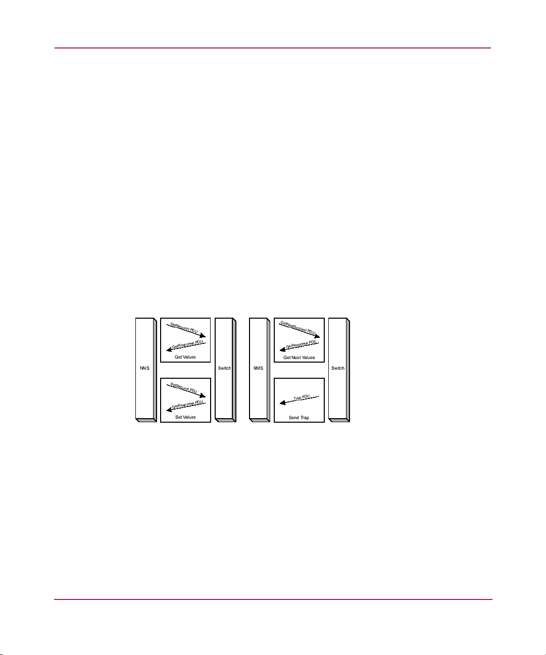
A manager requests information from an agent by sending a single command, the
Get command. The Get command also has a variation (GetNextRequest)
that permits more efficient operation:
■ GetRequest – Requests the value of a specified variable on the agent. This
command is used to retrieve management data.
■ GetNextRequest – Requests the value of the next variable after the one
specified in the command. This command is used to retrieve lists and tables of
management data.
An agent responds to a request by sending a single command, the GetResponse
command. This command contains the requested information.
A manager changes information (variables) in the agent by sending a single
command, the SetRequest command. This command is used to manipulate
management data.
A trap is used by an agent to report extraordinary events. Refer to “Traps and
Their Purpose” on page 19. Figure 1 illustrates SNMP commands and responses:
Introduction to SNMP
Figure 1: SNMP commands and responses
Why Variables Exist in a Managed Device
Variables are the means by which a Director or Edge Switch (and other devices)
keep track of their performance, control their own performance, and provide
access to information about their performance for network managers. A simple
example of a variable’s use is to set a port offline and turn the port back on. Some
variables just hold values that indicate status (for example, error counts). SNMP
allows network managers to have access to some of the same variables for
network management.
17SNMP Reference for Directors and Edge Switches
Page 18
Introduction to SNMP
Note: For purposes of the following explanation, an object is a data variable that
represents an attribute of a managed device.
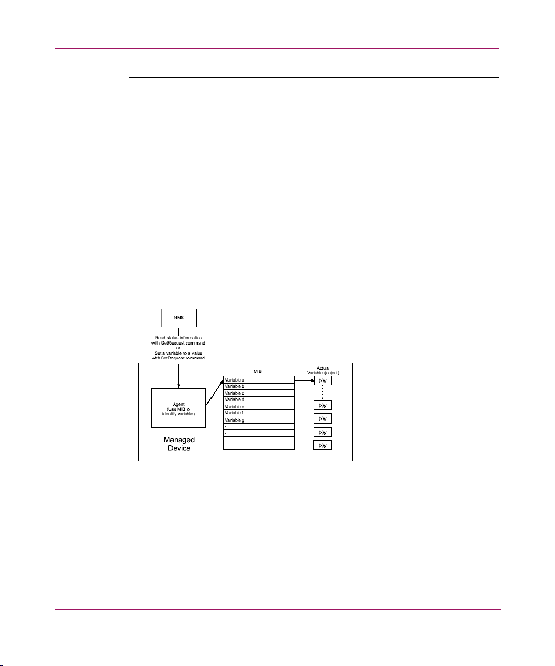
How SNMP Changes Variables (Objects) in a Managed Device
An agent is the entity that interfaces to the object being managed (Figure 2). The
agent understands the language of SNMP and translates between the manager and
the object. Objects may be retrieved and/or modified by the manager, and it is the
agent’s job to return the requested object’s value.
Within the agent is at least one, possibly several, collections of definitions called
Management Information Bases (MIBs). When an agent supports a standard MIB,
it agrees to provide and make available the variables listed in the MIB.
A MIB is a hierarchical tree of groups and variables. Operators at a network
management station enter a command with supported groups and variables from
the MIB.
Figure 2: Retrieving or setting values using MIBs
Standard MIBs
Standard MIBs are those available with SNMP and designed for standard
operation with a wide variety of managed devices. “SNMP Support” on page 21
describes the standard MIBs used by HP StorageWorks Directors, Edge Switches,
and the HA-Fabric Manager (HAFM) application.
18 SNMP Reference for Directors and Edge Switches
Page 19

Standard MIBs are:
■ MIB-II (Internet MIB), as described in RFC 1213: supported by all Directors
and Edge Switches.
■ Fibre Alliance (FCMGMT) MIB, version 3.1: supported by all Directors and
Edge Switches.
■ Fibre Channel Fabric Element (FCFE), version 1.10: supported by all
Directors, Edge Switches, and HAFM.
Private Enterprise MIBs
Private MIBs are those provided by the manufacturer of the managed devices to
allow management of device-specific items. “SNMP Support” on page 21
describes the private MIBs in more detail.
The private enterprise MIB is the FCEOS MIB, which is used by Directors and
Edge Switches to support zoning, port binding, threshold alerts, and trunking.
Traps and Their Purpose
Traps are unsolicited status reports, or status change indicators, that a managed
object sends to a network manager. The destination address for traps is a
configuration item for each managed agent.
Introduction to SNMP
19SNMP Reference for Directors and Edge Switches
Page 20

Introduction to SNMP
20 SNMP Reference for Directors and Edge Switches
Page 21

SNMP Support
This chapter describes SNMP support for HP StorageWorks Directors, Edge
Switches, and the HA-Fabric Manager (HAFM) server.
2
21SNMP Reference for Directors and Edge Switches
Page 22

SNMP Support
SNMP Management
SNMP is a protocol that uses the User Data Protocol (UDP) to exchange messages
between an SNMP agent (in a managed device) and a management station
residing on a network. Although SNMP can be made available over other
protocols, HP StorageWorks Directors, Edge Switches, and the HA-Fabric
Manager (HAFM) application only support UDP.
Overview
To be monitored and managed remotely by a network management station, each
Edge Switch or Director is equipped with an SNMP agent. This agent is a
software process within the switch that receives management requests and
generates corresponding responses by accessing the data specified for the MIB-II,
Fabric Element MIB, Fibre Alliance MIB, or FCEOS enterprise-specific MIB. In
addition, the agent gives each switch the ability to notify a management station
when an important event occurs, by sending a trap to the management station.
Six MIBs are supported:
■ A subset of the Standard MIB-II for TCP/IP-based Internet, as specified in
RFC 1213.
■ Fabric Element MIB containing support for FL_Ports, as specified in Fibre
Channel standards.
■ Fibre Alliance MIB (also referred to as the FC Management MIB), v3.0.
■ Fibre Alliance MIB (also referred to as the FC Management MIB), v3.1.
■ FCEOS MIB, which is the HP enterprise-specific MIB supporting HP Edge
Switch and Director firmware.
■ SNMP Framework MIB.
EOS Trap Overview
All EOS traps are SNMPv1 format, regardless of MIB definition syntax.)
SNMP traps are specific types of SNMP messages enclosed in user datagram
protocol (UDP) packets as shown:
[ IP Packet [ UDP Packet [ SNMP Message ] ] ]
The SNMP message format is:
[ Version | Community | SNMP PDU ]
22 SNMP Reference for Directors and Edge Switches
Page 23

SNMP Support
There are different formats for the SNMP protocol data units (PDUs), including
trap PDUs, for SNMPv1 and SNMPv2. These are summarized here:
SNMPv1 Trap PDU:
[ Enterprise | Agent address | Generic trap type |
Specific trap code | Time stamp | Object/Value 1 |
Object/Value 2…. ]
The following descriptions summarize these fields:
■ Enterprise—Identifies the type of managed object generating the trap.
■ Agent address—Provides the address of the managed object generating the
trap.
■ Generic trap type—Indicates one of a number of generic trap types.
■ Specific trap code—Indicates one of a number of specific trap codes.
■ Time stamp—Provides the amount of time that has elapsed between the last
network reinitialization and generation of the trap.
■ Variable bindings—The data field of the SNMPv1 Trap PDU. Each variable
binding associates a particular object instance with its current value.
The following descriptions summarize the fields illustrated below for the
SNMPv2 PDU format:
■ PDU type—Identifies the type of PDU transmitted (Get, GetNext, Inform,
Response, Set, or Trap).
■ Request ID—Associates SNMP requests with responses.
■ Error status—Indicates one of a number of errors and error types. Only the
response operation sets this field. Other operations set this field to zero.
■ Error index—Associates an error with a particular object instance. Only the
response operation sets this field. Other operations set this field to zero.
■ Variable bindings—Serves as the data field of the SNMPv2 PDU. Each
variable binding associates a particular object instance with its current value
(with the exception of Get and GetNext requests, for which the value is
ignored).
Get, GetNext, Inform, Response, Set, and Trap PDUs Contain the Same Fields:
[PDU type | Request ID | Error status | Error index |
Object/Value 1 | Object/Value 2]
23SNMP Reference for Directors and Edge Switches
Page 24

SNMP Support
For the SNMPv2 trap PDU, the first and second variable bindings contain the
uptime and the trap OID, respectively. Following the uptime and trap OID are all
the variable bindings specified in the MIB for that particular trap.
EOS Trap Summary Table
This table shows the different kinds of traps supported by the switch EOS
firmware.
Note: All EOS traps are SNMPv1 format, regardless of MIB definition syntax.
Sent
Trap Severity
Generic
Authentication
Failure
Generic Link Up N/A RFC-1157 YES NO
Generic Warm
Start
Generic Cold
Start
ES Port Change N/A A change in
ES Fru Change N/A A change in
ES Invalid
Attachment
ES Threshold
Alert
N/A SNMP
N/A Software
N/A Power up. RFC-1157 YES NO
N/A Invalid
N/A Threshold
Because:
request
from an
invalid
community
is received.
reset.
port status.
FRU status.
attachment
to a port.
specified in
threshold
table has
been
exceeded
for a port.
MIB Trap OID EOS HAFM
RFC-1157 YES NO
RFC-1157 YES NO
FCEOS 1.3.6.1.4.1.289.1 YES NO
FCEOS 1.3.6.1.4.1.289.2 YES NO
FCEOS 1.3.6.1.4.1.289.3 YES NO
FCEOS 1.3.6.1.4.1.289.4 YES NO
24 SNMP Reference for Directors and Edge Switches
Page 25

SNMP Support
Switch SCN Alert Change in
switch
status.
Event SCN Info New system
event was
generated.
Sensor SCN Alert Change in
status for
FAN /FAN2/
POWER
FRUs.
Port SCN Alert Change in
port status.
Following are sections describing each trap, and the variables within the traps. For
each variable, the OID is expressed as a numeric value first, followed by a second
line showing the symbolic object name. Appended to the right of the OIDs are the
index values for each object. Most of the objects within traps are actually table
values.
Each SNMP table value must have an index appended to identify a specific table
row. For example, the enterprise-specific port status change trap has the variable
binding for fcEosPortOpStatus, which is a table entry value. So the OID for
fcEosPortOpStatus (1.3.6.1.4.1.289.2.1.1.2.3.1.1.3) specifies a table column. To
get a value for a specific port, the table index (port_number) must be appended to
the OID. If the trap occurred because of a change on port 5, the actual variable
OID would be 1.3.6.1.4.1.289.2.1.1.2.3.1.1.3.5.
FC-MGMNT 1.3.6.1.2.1.8888.0.1 YES YES
FC-MGMNT 1.3.6.1.2.1.8888.0.3 YES YES
FC-MGMNT 1.3.6.1.2.1.8888.0.4 YES YES
FC-MGMNT 1.3.6.1.2.1.8888.0.5 YES YES
Enterprise-specific Port Status Change Trap
This trap is sent for each port that has a status change. There is one variable
binding, as follows:
Binding OID Value
1 1.3.6.1.4.1.289.2.1.1.2.3.1.1.3.port_number
fcEosPortOpStatus.port_number
New status value. See definition for
“fcEosPortOpStatus” on page 133.
25SNMP Reference for Directors and Edge Switches
Page 26

SNMP Support
Enterprise-specific FRU Status Change Trap
This trap is sent for each FRU that has a status change. There is one variable
binding, as follows:
Binding OID Value
1 1.3.6.1.4.1.289.2.1.1.2.2.1.1.3.fru_code.fru_pos
fcEosFruStatus.fru_code.fru_pos
Where fru_code has one of the following values:
0x01, Backplane
0x02, Control Processor card
0x03, Serial crossbar
0x04, ES-3032 center fan module
0x05, Fan module
0x06, Power supply module
0x07, Reserved
0x08, Longwave, Single-Mode, LC connector, 1 Gig (Port
card)
0x09, Shortwave, Multi-Mode, LC connector, 1 Gig (Port card)
0x0A, Mixed, LC connector, 1 Gig (Port card)
0x0B, SFO pluggable, 1 Gig
0x0C, SFO pluggable, 2 Gig
0x0D, Longwave, Single-Mode, MT-RJ connector, 1 Gig
0x0E, Shortwave, Multi-Mode, MT-RJ connector, 1 Gig
0x0F, Mixed, MT-RJ connector, 1 Gig
0x10, F-Port, internal, 1 Gig
New status value.
See definition for
“fcEosFruStatus” on
page 133.
And where fru_pos is a number specific to each possible FRU
position, which varies from product to product. For example, on
a Director 2/140 there are three fans, numbered 1 to 3.
26 SNMP Reference for Directors and Edge Switches
Page 27

Enterprise-specific Invalid Attachment Trap
This trap is sent when an invalid attachment occurs (a device is attached, with a
World Wide Name WWN specifically disallowed by port binding). There is one
variable binding.
Binding OID Value
1 1.3.6.1.4.1.289.2.1.1.2.4.1.1.4.port_number
fcEosPortAttachedWWN.port_number
WWN of invalid attached device.
See definition for
“fcEosPortAttachedWWN” on
page 139.
Enterprise-specific Threshold Alert Trap
This trap is sent when port traffic exceeds a specified threshold. There are two
variable bindings.
Binding OID Value
1 1.3.6.1.4.1.289.2.1.1.2.3.1.1.1.port_number
fcEosPortIndex.port_number
2 1.3.6.1.4.1.289.2.1.1.2.6.1.1.1.threshold_number
fcEosTAIndex.threshold_number
Port number of port with
threshold alert.
The index of the threshold
which was triggered.
SNMP Support
FA MIB Switch Status Change Trap
This trap is sent when the switch status changes. There are two variable bindings.
Binding OID Value
1 1.3.6.1.2.1.8888.1.1.3.1.6.<unit-id>
fcConnUnitStatus.<unit-id>
Where unit-id is the WWN of the switch,
with 8 zeros appended, for a total length of
16. Example:
1.2.3.4.5.6.7.8.0.0.0.0.0.0.0.0
2 1.3.6.1.2.1.8888.1.1.3.1.5.<unit-id>
fcConnUnitState.<unit-id>
Where unit-id is the WWN of the switch,
with 8 zeros appended, for a total length of
16. Example:
1.2.3.4.5.6.7.8.0.0.0.0.0.0.0.0
Unit status. See definition for
“FcConnUnitStatus” on page 91.
Unit state. See definition for
“FcConnUnitStatus” on page 91.
27SNMP Reference for Directors and Edge Switches
Page 28

SNMP Support
FA MIB Event Trap
This trap is sent when an internal software event is generated. There are four
variable bindings.
Binding OID Value
1 1.3.6.1.2.1.8888.1.1.3.1.1.<unit-id>
fcConnUnitId.<unit-id>
Where unit-id is the WWN of the switch, with 8
zeros, appended for a total length of 16.
Example: 1.2.3.4.5.6.7.8.0.0.0.0.0.0.0.0
The value is the same as unit-id: the
WWN of the switch, with 8 zeros
appended, for a total length of 16.
Example:
1.2.3.4.5.6.7.8.0.0.0.0.0.0.0.0
28 SNMP Reference for Directors and Edge Switches
Page 29

SNMP Support
2 1.3.6.1.2.1.8888.1.1.7.1.5.<unit-id><event-in
dex>
fcConnUnitEventType.<unit-id><event-index>
Where unit-id is the WWN of the switch with 8
zeros appended for a total length of 16.
Example: 1.2.3.4.5.6.7.8.0.0.0.0.0.0.0.0
And where event-index is an integer index of
the event table, a unique incrementing value
assigned to each event. The event table always
contains the most recent 200 events which met
the filter criteria in place when the event
occurred.
3 1.3.6.1.2.1.8888.1.1.7.1.6.<unit-id><event-in
dex>
fcConnUnitEventType.<unit-id><event-index>
Where unit-id is the WWN of the switch with 8
zeros appended for a total length of 16.
Example: 1.2.3.4.5.6.7.8.0.0.0.0.0.0.0.0
And where event-index is an integer index of
the event table, a unique incrementing value
assigned to each event. The event table always
contains the most recent 200 events which met
the filter criteria in place when the event
occurred.
4 1.3.6.1.2.1.8888.1.1.7.1.7.<unit-d><event-in
dex>
fcConnUnitEventDescr.<unit-id><event-index>
Where unit-id is the WWN of the switch, with 8
zeros appended, for a total length of 16.
Example: 1.2.3.4.5.6.7.8.0.0.0.0.0.0.0.0
And where event-index is an integer index of
the event table, a unique incrementing value
assigned to each event. The event table always
contains the most recent 200 events which met
the filter criteria in place when the event
occurred.
See definition for
“FcConnUnitEventType” on
page 111.
The value of this variable is the OID
for fcConnUnitId:
1.3.6.1.2.1.8888.1.1.3.1.1.<unitid>
Where unit-id is the WWN of the
switch, with 8 zeros appended, for
a total length of 16. Example:
1.2.3.4.5.6.7.8.0.0.0.0.0.0.0.0
Event description string with a
maximum length of 80 characters.
This string will contain a numeric
event code and other values
describing the specific event.
29SNMP Reference for Directors and Edge Switches
Page 30

SNMP Support
FA MIB Sensor Trap
This trap is generated whenever a status change occurs for a fan or power supply
FRU. There is one variable binding.
Binding OID Value
1 1.3.6.1.2.1.8888.1.1.5.1.3.<unit-id>.<sensor-index>
fcConnUnitSensorStatus.<unit-id>.<sensor-index>
Where unit-id is the WWN of the switch, with 8 zeros
appended, for a total length of 16. Example:
1.2.3.4.5.6.7.8.0.0.0.0.0.0.0.0
And where sensor-index refers to the FRU in the sensor
table which has changed state. For example if
sensor-index was 5, you could look at the 5
the sensor table to determine which FRU was affected.
th
entry in
See description for
“FcConnUnitSensorStatus” on
page 96.
FA MIB Port Status Change Trap
This trap occurs whenever a port status change occurs. There are two variable
bindings.
Binding OID Value
1 1.3.6.1.2.1.8888.1.1.6.1.6.<port-index>
fcConnUnitPortStatus.<port-index>
Where port-index is the port number
normalized to the range 1-140.
2 1.3.6.1.2.1.8888.1.1.6.1.5.<port-index>
fcConnUnitPortState.<port-index>
Where port-index is the port number
normalized to the range 1-140.
See definition for
“FcConnUnitPortStatus” on page 101.
See definition for
“FcConnUnitPortStatus” on page 101.
Example
Interpretation of trap information from HP OpenView
The output from HP OpenView for a series of traps is shown below:
- Minor Thu May 02 09:29:30 10.235.4.111 NO
TRAPD.CONF FMT FOR .1.3.6.1.2.1.8888.0.1 ARGS(2):
[1]
mgmt.mib-2.fcMgmtMIB.fcMgmtObjects.fcMgmtConfig.fcC
onnUnitTable.fcConnUnitEntry.fcConnUnitStatus.3.2.0
.0.0.0.0.0.0.0.0.0.0.0.0.0 (Integer): ok [2]
30 SNMP Reference for Directors and Edge Switches
Page 31

SNMP Support
mgmt.mib-2.fcMgmtMIB.fcMgmtObjects.fcMgmtConfig.fcC
onnUnitTable.fcConnUnitEntry.fcConnUnitState.3.2.0.
0.0.0.0.0.0.0.0.0.0.0.0.0 (Integer): online
- Minor Thu May 02 09:29:31 10.235.4.111 NO
TRAPD.CONF FMT FOR .1.3.6.1.2.1.8888.0.1 ARGS(2):
[1]
mgmt.mib-2.fcMgmtMIB.fcMgmtObjects.fcMgmtConfig.fcC
onnUnitTable.fcConnUnitEntry.fcConnUnitStatus.7.0.0
.0.0.0.0.0.0.0.0.0.0.0.0.0 (Integer): ok [2]
mgmt.mib-2.fcMgmtMIB.fcMgmtObjects.fcMgmtConfig.fcC
onnUnitTable.fcConnUnitEntry.fcConnUnitState.7.0.0.
0.0.0.0.0.0.0.0.0.0.0.0.0 (Integer): online
- Minor Thu May 02 09:29:46 10.235.4.111 NO
TRAPD.CONF FMT FOR .1.3.6.1.2.1.8888.0.1 ARGS(2):
[1]
mgmt.mib-2.fcMgmtMIB.fcMgmtObjects.fcMgmtConfig.fcC
onnUnitTable.fcConnUnitEntry.fcConnUnitStatus.3.2.0
.0.0.0.0.0.0.0.0.0.0.0.0.0 (Integer): ok [2]
mgmt.mib-2.fcMgmtMIB.fcMgmtObjects.fcMgmtConfig.fcC
onnUnitTable.fcConnUnitEntry.fcConnUnitState.3.2.0.
0.0.0.0.0.0.0.0.0.0.0.0.0 (Integer): online
- Minor Thu May 02 09:29:47 10.235.4.111 NO
TRAPD.CONF FMT FOR .1.3.6.1.2.1.8888.0.1 ARGS(2):
[1]
mgmt.mib-2.fcMgmtMIB.fcMgmtObjects.fcMgmtConfig.fcC
onnUnitTable.fcConnUnitEntry.fcConnUnitStatus.7.0.0
.0.0.0.0.0.0.0.0.0.0.0.0.0 (Integer): ok [2]
mgmt.mib-2.fcMgmtMIB.fcMgmtObjects.fcMgmtConfig.fcC
onnUnitTable.fcConnUnitEntry.fcConnUnitState.7.0.0.
0.0.0.0.0.0.0.0.0.0.0.0.0 (Integer): online
This output from HP OpenView contains information for four traps. Blank lines
have been added for clarity.
The first step is to determine which trap caused this output. Looking after the
words NO TRAPD. CONF FMT FOR, you can see the numbers
1.3.6.1.2.1.8888.0.1, which identifies this as a switch SCN trap.
After the trap OID, the variable bindings are listed. HP OpenView calls them
“ARGS” and shows how many have been found in this particular trap (in this
case, 2).
31SNMP Reference for Directors and Edge Switches
Page 32

SNMP Support
The first ARG is identified by its OID in symbolic form:
mgmt.mib-2.fcMgmtMIB.fcMgmtObjects.fcMgmtConfig.fcConn
UnitTable.fcConnUnitEntry.fcConnUnitStatus.
The numbers following fcConnUnitStatus are the unit-id, which identifies a
particular switch in a fabric. (The unit-id is the first index for all tables in the Fibre
Alliance MIB). In this case, these traps are most likely from HAFM, which uses a
different numbering scheme for the unit-id than the EOS firmware (see below). In
both cases the unit-id is a string of 16 numbers. Following the unit-id is the actual
value of the first variable: ok. The value transmitted in the trap is numeric (an
integer) but HP OpenView has cross-referenced this numeric value with the MIB
definitions to provide the symbolic form (ok). The second variable binding is
fcConnUnitState and has the same indexing scheme for unit-id.
Numbering scheme for unit-id (fcConnUnitId) for EOS and HAFM:
EOS: WWN(8 numbers).0.0.0.0.0.0.0.0
HAFM: product-code.product-id.0.0.0.0.0.0.0.0.0.0.0.0.0.0
In both cases the total length is 16 numbers.
This identifier is used as the first index in all FA MIB tables.
Example
Interpretation of trap information from the MIB Browser:
1. 3: Specific trap #3 trap(v1) received from:
172.16.7.243 at 09/25/2002 3:06:45 PM
Time stamp: 0 days 00h:00m:12s.36th
Agent address: 172.16.7.243 Port: 161 Transport:
IP/UDP Protocol: SNMPv1 Trap
Manager address: 172.16.7.107 Port: 162 Transport:
IP/UDP
Community: public
SNMPv1 agent address: 172.16.7.243
Enterprise: fcMgmtMIB
Specific Trap MIB Lookup Results
Name: fcEosPortBindingViolation, Module: FCEOS-MIB,
Enterprise: HP
Bindings (4)
Binding #1:
32 SNMP Reference for Directors and Edge Switches
Page 33

SNMP Support
fcConnUnitId.16.0.8.0.136.122.40.0.0.0.0.0.0.0.0.0
*** (octets)
00.00.00.10.00.00.00.00.00.00.00.08.00.00.00.00
(hex)
Binding #2:
fcConnUnitEventType.16.0.8.0.136.122.40.0.0.0.0.0.0
.0.0.0.295 *** (int32) status(3)
Binding #3:
fcConnUnitEventObject.16.0.8.0.136.122.40.0.0.0.0.0
.0.0.0.0.295 *** (oid)
fcConnUnitId.16.0.8.0.136.122.40.0.0.0.0.0.0.0.0.0
Binding #4:
fcConnUnitEventDescr.16.0.8.0.136.122.40.0.0.0.0.0.
0.0.0.0.295 *** (octets) Reason code
410<00><00><00><00><00><00><00><00><00><00><00><00>
<00><00><00><00><00><00><00><00><00><00><00><00><00
><00><00><00><00><00><00><00><00><00><00><00><00
...
2. 4: Specific trap #1 trap(v1) received from:
172.16.7.243 at 09/25/2002 3:06:45 PM
3. 5: Specific trap HP::fcEosFruScn #2 trap(v1)
received from: 172.16.7.243 at 09/25/2002 3:06:45 PM
4. 6: Specific trap #3 trap(v1) received from:
172.16.7.243 at 09/25/2002 3:06:45 PM
5. 7: Specific trap #3 trap(v1) received from:
172.16.7.243 at 09/25/2002 3:06:45 PM
As displayed by the MIB browser, the output above is shown in hierarchical tree
form. Trap number 3 has been expanded to show the details of the information
contained in the trap. The agent address is the IP address of the switch, and the
management address is the address of the PC which was running the MIB
browser. In this case the trap can be identified by the Enterprise (fcMgmtMIB –
also known as the FA MIB) and the specific trap number (3), which identifies this
as an FA MIB event trap. Lines labeled 4-7 are each for different traps. Referring
to trap 3 again, the browser clearly displays the four variable bindings contained
within a FA MIB event trap. Each variable binding is displayed in the format:
OID data-type value.
33SNMP Reference for Directors and Edge Switches
Page 34

SNMP Support
MIB Definitions
This section provides definitions for the following MIBs:
■ MIB-II, page 34
■ Fabric Element Management MIB, page 63
■ Fibre Alliance MIB, page 85
■ Private (Enterprise-specific) FCEOS MIB, page 130
MIB-II
There are eleven groups of objects specified in MIB-II. The EOS SNMP agent
supports eight groups:
■ System group. This group provides general information about the managed
system.
■ Interfaces group.
■ Address Translation group. This group is implemented, but the corresponding
table may be empty.
■ IP group.
■ ICMP group.
■ TCP group.
■ UDP group.
■ SNMP group. This group keeps statistics on the SNMP agent implementation
itself.
34 SNMP Reference for Directors and Edge Switches
Page 35

SNMP Support
System Group
MIB-2
Object
Name
sysDescr DisplayString(0..255) R A textual description of the entity. This value
sysObjectID Object Identifier R The vendor’s authoritative identification of
sysUpTime TimeTicks R The time (in hundredths of a second) since
sysContact DisplayString (0..255) R The textual identification of the contact
Type Access Description
should include the full name and version
identification of the system's hardware type,
software operating-system, and networking
software. It is mandatory that this only
contain printable ASCII characters.
the network management subsystem
contained in the entity. This value is allocated
within the SMI enterprises subtree
(1.3.6.1.4.1) and provides an easy and
unambiguous means for determining “what
kind of box” is being managed. For
example, if vendor “Flintstones, Inc.” was
assigned the subtree 1.3.6.1.4.1.4242, it
could assign the identifier
1.3.6.1.4.1.4242.1.1 to its “Fred Router.”
the network management portion of the
system was last re-initialized.
person for this managed node, together with
information on how to contact this person.
35SNMP Reference for Directors and Edge Switches
Page 36

SNMP Support
sysName DisplayString (0..255) RW An administratively-assigned name for this
managed node. By convention, this is the
node's fully-qualified domain name.
sysLocation DisplayString (0..255) RW The physical location of this node (for
example, “telephone closet, 3rd floor”).
sysServices INTEGER R A value which indicates the set of services
that this entity primarily offers. The value is a
sum. This sum initially takes the value zero,
Then, for each layer, L, in the range 1
through 7, that this node performs
transactions for, 2 raised to (L - 1) is added
to the sum.
For example, a node which performs
primarily routing functions would have a
value of 4 (2^(3-1)). In contrast, a node
which is a host offering application services
would have a value of 72 (2^(4-1) +
2^(7-1)).
Note that in the context of the Internet suite of
protocols, values should be calculated
accordingly:
layer functionality
1 physical (for example, repeaters)
2 datalink/subnetwork (for example,
bridges)
3 Internet (for example, IP gateways)
4 end-to-end (for example, IP hosts)
7 applications (for example, mail
relays)
For systems including OSI protocols, layers 5
and 6 may also be counted.
36 SNMP Reference for Directors and Edge Switches
Page 37

SNMP Support
Interfaces Group
MIB-2
Object
Name
ifNumber INTEGER R The number of network interfaces (regardless
Type Access Description
of their current state) present on this system.
Interfaces Table
The Interfaces table contains information on the entity's interfaces. Each interface
is thought of as being attached to a subnetwork. Note that this term should not be
confused with subnet, which refers to an addressing partitioning scheme used in
the Internet suite of protocols.
MIB-2 Object
Name
ifIndex INTEGER R A unique value for each interface. Its
ifDescr DisplayString(0..255) R A textual string containing information
Type Access Description
value ranges between 1 and the value of
ifNumber. The value for each interface
must remain constant at least from one
re-initialization of the entity's network
management system to the next
re-initialization
about the interface. This string should
include the name of the manufacturer, the
product name, and the version of the
hardware interface.
37SNMP Reference for Directors and Edge Switches
Page 38

SNMP Support
ifType INTEGER R The type of interface, distinguished
according to the physical/link protocol(s)
immediately “below” the network layer in
the protocol stack.
Values:
other(1), none of the following
regular1822(2),
hdh1822(3),
ddn-x25(4),
rfc877-x25(5),
ethernet-csmacd(6),
iso88023-csmacd(7),
iso88024-tokenBus(8),
iso88025-tokenRing(9),
iso88026-man(10),
starLan(11),
proteon-10Mbit(12),
proteon-80Mbit(13),
hyperchannel(14),
fddi(15),
lapb(16),
sdlc(17),
ds1(18), T-1
e1(19), european equiv. of T-1
basicISDN(20),
primaryISDN(21), proprietary serial
propPointToPointSerial(22),
ppp(23),
softwareLoopback(24),
eon(25), - CLNP over IP [11]
ethernet-3Mbit(26),
nsip(27), - XNS over IP
slip(28), - generic SLIP
ultra(29), - ULTRA technologies
ds3(30), - T-3
sip(31), - SMDS
frame-relay(32)
38 SNMP Reference for Directors and Edge Switches
Page 39

SNMP Support
ifMtu INTEGER R The size of the largest datagram that can
be sent/received on the interface,
specified in octets. For interfaces that are
used for transmitting network datagrams,
this is the size of the largest network
datagram that can be sent on the
interface.
ifSpeed Gauge R An estimate of the interface's current
bandwidth in bits per second. For
interfaces which do not vary in bandwidth
or for those where no accurate estimation
can be made, this object should contain
the nominal bandwidth.
ifPhysAddress PhysAddress R The interface's address at the protocol
layer immediately “below” the network
layer in the protocol stack. For interfaces
which do not have such an address (for
example, a serial line), this object should
contain an octet string of zero length.
ifAdminStatus INTEGER RW The desired state of the interface. The
testing(3) state indicates that no
operational packets can be passed.
ifOperStatus INTEGER R The current operational state of the
interface. The testing(3) state indicates
that no operational packets can be
passed.
ifLastChange TimeTicks R The value of sysUpTime at the time the
interface entered its current operational
state. If the current state was entered prior
to the last re-initialization of the local
network management subsystem, this
object contains a zero value.
ifInOctets Counter R The total number of octets received on the
interface, including framing characters.
ifInUcastPkts Counter R The number of subnetwork-unicast
packets delivered to a higher-layer
protocol.
ifInNUcastPkts Counter R The number of non-unicast (i.e.,
subnetwork-broadcast or
subnetwork-multicast) packets delivered to
a higher-layer protocol.
39SNMP Reference for Directors and Edge Switches
Page 40

SNMP Support
ifInDiscards Counter R The number of inbound packets which
were chosen to be discarded even though
no errors had been detected to prevent
their being deliverable to a higher-layer
protocol. One possible reason for
discarding such a packet could be to free
up buffer space.
ifInErrors Counter R The number of inbound packets that
contained errors preventing them from
being deliverable to a higher-layer
protocol.
ifInUnknownProtos Counter R The number of packets received via the
interface which were discarded because
of an unknown or unsupported protocol.
ifOutOctets Counter R The total number of octets transmitted out
of the interface, including framing
characters.
ifOutUcastPkts Counter R The total number of packets that
higher-level protocols requested be
transmitted to a subnetwork-unicast
address, including those that were
discarded or not sent.
ifOutNUcastPkts Counter R The total number of packets that
higher-level protocols requested be
transmitted to a non-unicast (i.e., a
subnetwork-broadcast or
subnetwork-multicast) address, including
those that were discarded or not sent.
ifOutDiscards Counter R The number of outbound packets which
were chosen to be discarded even though
no errors had been detected to prevent
their being transmitted. One possible
reason for discarding such a packet could
be to free up buffer space.
40 SNMP Reference for Directors and Edge Switches
Page 41

SNMP Support
ifOutErrors Counter R The number of outbound packets that
could not be transmitted because of
errors.
ifOutQLen Gauge R The length of the output packet queue (in
packets).
ifSpecific OBJECT IDENTIFIER R A reference to MIB definitions specific to
the particular media being used to realize
the interface. For example, if the interface
is realized by an Ethernet, the value of this
object refers to a document defining
objects specific to Ethernet. If this
information is not present, its value should
be set to the OBJECT IDENTIFIER { 0 0 },
which is a syntactically valid object
identifier, and any conforming
implementation of ASN.1 and BER must
be able to generate and recognize this
value.
Address Translation Group/Table
Implementation of the Address Translation group is mandatory for all systems.
Note however that this group is deprecated by MIB-II. That is, it is being included
solely for compatibility with MIB-I nodes, and will most likely be excluded from
MIB-III nodes. From MIB-II and onwards, each network protocol group contains
its own address translation tables.
The Address Translation group contains one table, which is the union across all
interfaces of the translation tables for converting a NetworkAddress (for example,
an IP address) into a subnetwork-specific address. For lack of a better term, this
document refers to such a subnetwork-specific address as a `physical' address.
Examples of such translation tables are: for broadcast media where ARP is in use,
the translation table is equivalent to the ARP cache; or, on an X.25 network where
non-algorithmic translation to X.121 addresses is required, the translation table
contains the NetworkAddress to X.121 address equivalences.
41SNMP Reference for Directors and Edge Switches
Page 42

SNMP Support
MIB-2
Object
Name
Type Access Description
atIfIndex INTEGER RW The interface on which this entry's
equivalence is effective. The interface
identified by a particular value of this index
is the same interface as identified by the
same value of ifIndex.
atPhysAddressPhysAddress RW The media-dependent “physical” address.
Setting this object to a null string (one of
zero length) has the effect of invaliding the
corresponding entry in the atTable object;
that is, it effectively disassociates the
interface identified with said entry from the
mapping identified with said entry. It is an
implementation-specific matter as to
whether the agent removes an invalidated
entry from the table. Accordingly,
management stations must be prepared to
receive tabular information from agents that
corresponds to entries not currently in use.
Proper interpretation of such entries requires
examination of the relevant atPhysAddress
object.
atNetAddress NetworkAddress RW The NetworkAddress (for example, the IP
address) corresponding to the
media-dependent “physical” address.
42 SNMP Reference for Directors and Edge Switches
Page 43

SNMP Support
IP Group
MIB-2 Object
Name
ipForwarding INTEGER RW The indication of whether this entity is
ipDefaultTTL INTEGER RW The default value inserted into the
ipInReceives Counter R The total number of input datagrams
ipInHdrErrors Counter R The number of input datagrams
ipInAddrErrors Counter R The number of input datagrams
Type Access Description
acting as an IP gateway in respect to
the forwarding of datagrams received
by, but not addressed to, this entity. IP
gateways forward datagrams. IP hosts
do not (except those source-routed via
the host). Note that for some managed
nodes, this object may take on only a
subset of the values possible.
Accordingly, it is appropriate for an
agent to return a “bedevil” response if
a management station attempts to
change this object to an inappropriate
value.
Time-To-Live (TTL) field of the IP header
of datagrams originated at this entity,
whenever a TTL value is not supplied
by the transport layer protocol.
received from interfaces, including
those received in error.
discarded due to errors in their IP
headers, including bad checksums,
version number mismatches, other
format errors, time-to-live exceeded,
errors discovered in processing their IP
options, and so forth.
discarded because the IP address in
their IP header's destination field was
not a valid address to be received at
this entity. This count includes invalid
addresses (for example, 0.0.0.0) and
addresses of unsupported Classes (for
example, Class E). For entities which
are not IP Gateways and therefore do
not forward datagrams, this counter
includes datagrams discarded because
the destination address was not a local
address.
43SNMP Reference for Directors and Edge Switches
Page 44

SNMP Support
ipForwDatagrams Counter R The number of input datagrams for
which this entity was not their final IP
destination. As a result, an attempt
was made to find a route to forward
them to that final destination. In entities
which do not act as IP Gateways, this
counter will include only those packets
which were Source-Routed via this
entity, and the Source-Route option
processing was successful.
ipInUnknownProtos Counter R The number of locally-addressed
datagrams received successfully but
discarded because of an unknown or
unsupported protocol.
ipInDiscards Counter R The number of input IP datagrams for
which no problems were encountered
to prevent their continued processing,
but which were discarded (for
example, for lack of buffer space).
Note that this counter does not include
any datagrams discarded while
awaiting re-assembly.
ipInDelivers Counter R The total number of input datagrams
successfully delivered to IP
user-protocols (including ICMP).
ipOutRequests Counter R The total number of IP datagrams
which local IP user-protocols (including
ICMP) supplied to IP in requests for
transmission. Note that this counter
does not include any datagrams
counted in ipForwDatagrams.
ipOutDiscards Counter R The number of output IP datagrams for
which no problem was encountered to
prevent their transmission to their
destination, but which were discarded
(for example, for lack of buffer space).
Note that this counter would include
datagrams counted in
ipForwDatagrams if any such packets
met this (discretionary) discard
criterion.
44 SNMP Reference for Directors and Edge Switches
Page 45

SNMP Support
ipOutDiscards Counter R The number of output IP datagrams for
which no problem was encountered to
prevent their transmission to their
destination, but which were discarded
(for example, for lack of buffer space).
Note that this counter would include
datagrams counted in
ipForwDatagrams if any such packets
met this (discretionary) discard
criterion.
ipOutNoRoutes Counter R The number of IP datagrams discarded
because no route could be found to
transmit them to their destination. Note
that this counter includes any packets
counted in ipForwDatagrams which
meet this “no-route” criterion. Note
that this includes any datagarms which
a host cannot route because all of its
default gateways are down.
ipReasmTimeout INTEGER R The maximum number of seconds that
received fragments are held while they
are awaiting reassembly at this entity.
ipReasmReqds Counter R The number of IP fragments received
which needed to be reassembled at
this entity.
ipReasmOKs Counter R The number of successful IP
datagrams.
ipReasmFails Counter R The number of failures detected by the
IP re-assembly algorithm (for whatever
reason: timed out, errors, and so
forth). Note that this is not necessarily
a count of discarded IP fragments
because some algorithms (notably the
algorithm in RFC 815) can lose track
of the number of fragments by
combining them as they are received.
45SNMP Reference for Directors and Edge Switches
Page 46

SNMP Support
ipFragOKs Counter R The number of IP datagrams that have
been successfully fragmented at this
entity.
ipFragFails Counter R The number of IP datagrams that have
been discarded because they needed
to be fragmented at this entity but
could not be, for example, because
their Don't Fragment flag was set.
ipFragCreates Counter R The number of IP datagram fragments
that have been generated as a result of
fragmentation at this entity.
IP Address Table
The IP address table contains this entity's IP addressing information.
MIB-2 Object
Name Type Access Description
ipAdEntAddr IpAddress R The IP address to which this entry's
addressing information pertains.
ipAdEntIfIndex INTEGER R The index value which uniquely
identifies the interface to which this
entry is applicable. The interface
identified by a particular value of this
index is the same interface as identified
by the same value of ifIndex.
46 SNMP Reference for Directors and Edge Switches
Page 47

SNMP Support
ipAdEntNetMask IpAddress R The subnet mask associated with the IP
address of this entry. The value of the
mask is an IP address with all the
network bits set to 1 and all the host’s
bits set to 0.
ipAdEntBcastAddr INTEGER R The value of the least-significant bit in
the IP broadcast address used for
sending datagrams on the (logical)
interface associated with the IP address
of this entry. For example, when the
Internet standard all-ones broadcast
address is used, the value will be 1.
This value applies to both the subnet
and network broadcasts addresses
used by the entity on this (logical)
interface.
ipAdEntReasmMax
Size
INTEGER (0..65535) R The size of the largest IP datagram that
this entity can re-assemble from
incoming IP fragmented datagrams
received on this interface.
IP Routing Table
The IP routing table contains an entry for each route presently known to this entity
MIB-2 Object
Name
ipRouteDest IpAddress RW The destination IP address of this route.
ipRouteIfIndex INTEGER RW The index value which uniquely identifies
Type Access Description
An entry with a value of 0.0.0.0 is
considered a default route. Multiple
routes to a single destination can appear
in the table, but access to such multiple
entries is dependent on the table access
mechanisms defined by the network
management protocol in use.
the local interface through which the next
hop of this route should be reached. The
interface identified by a particular value
of this index is the same interface as
identified by the same value of ifIndex.
47SNMP Reference for Directors and Edge Switches
Page 48

SNMP Support
ipRouteMetric1 INTEGER RW The primary routing metric for this route.
The semantics of this metric are
determined by the routing protocol
specified in the route's ipRouteProto
value. If this metric is not used, its value
should be set to -1.
ipRouteMetric2 INTEGER RW An alternate routing metric for this route.
The semantics of this metric are
determined by the routing protocol
specified in the route's ipRouteProto
value. If this metric is not used, its value
should be set to -1.
ipRouteMetric3 INTEGER RW An alternate routing metric for this route.
The semantics of this metric are
determined by the routing protocol
specified in the route's ipRouteProto
value. If this metric is not used, its value
should be set to -1.
ipRouteMetric4 INTEGER RW An alternate routing metric for this route.
The semantics of this metric are
determined by the routing protocol
specified in the route's ipRouteProto
value. If this metric is not used, its value
should be set to -1.
ipRouteNextHop IpAddress RW The IP address of the next hop of this
route. (In the case of a route bound to an
interface which is realized via a
broadcast media, the value of this field is
the agent's IP address on that interface.)
48 SNMP Reference for Directors and Edge Switches
Page 49

SNMP Support
ipRouteType INTEGER RW The type of route. Note that the values
direct(3) and indirect(4) refer to the
notion of direct and indirect routing in the
IP architecture. Setting this object to the
value invalid(2) has the effect of
invalidating the corresponding entry in
the ipRouteTable object. That is, it
effectively disassociates the destination
identified with said entry from the route
identified with said entry. It is an
implementation-specific matter as to
whether the agent removes an
invalidated entry from the table.
Accordingly, management stations must
be prepared to receive tabular
information from agents that corresponds
to entries not currently in use. Proper
interpretation of such entries requires
examination of the relevant ipRouteType
object.
Values:
other(1), - none of the following
invalid(2), - an invalidated route
direct(3), - route to directly connected
(sub-)network
indirect(4) - route to a
non-localhost/network/sub-network
49SNMP Reference for Directors and Edge Switches
Page 50

SNMP Support
ipRouteProto INTEGER R The routing mechanism via which this
route was learned. Inclusion of values for
gateway routing protocols is not intended
to imply that hosts should support those
protocols.
other(1), - none of the following
local(2), - non-protocol information, for
example, manually configured entries
netmgmt(3), - set via a network
management protocol
icmp(4), - for example, obtained via
ICMP,Redirect
The remaining values are all gateway
routing protocols:
egp(5),
ggp(6),
hello(7),
rip(8),
is-is(9),
es-is(10),
ciscoIgrp(11),
bbnSpfIgp(12),
ospf(13),
bgp(14)
ipRouteAge INTEGER RW The number of seconds since this route
was last updated or otherwise
determined to be correct. Note that no
semantics of `too old' can be implied
except through knowledge of the routing
protocol by which the route was learned.
50 SNMP Reference for Directors and Edge Switches
Page 51

SNMP Support
ipRouteMask IpAddress RW The mask to be logical-ANDed with the
destination address before being
compared to the value in the ipRouteDest
field. For those systems that do not
support arbitrary subnet masks, an agent
constructs the value of the ipRouteMask
by determining whether the value of the
correspondent ipRouteDest field belong to
a class-A, B, or C network, and then
using one of:
Mask Network
255.0.0.0 class-A
255.255.0.0 class-B
255.255.255.0 class-C
If the value of the ipRouteDest is 0.0.0.0
(a default route), the mask value is also
0.0.0.0. It should be noted that all IP
routing subsystems implicitly use this
mechanism.
ipRouteMetric5 INTEGER RW An alternate routing metric for this route.
The semantics of this metric are
determined by the routing protocol
specified in the route's ipRouteProto
value. If this metric is not used, its value
should be set to -1.
ipRouteInfo OBJECT IDENTIFIER R A reference to MIB definitions specific to
the particular routing protocol which is
responsible for this route, as determined
by the value specified in the route's
ipRouteProto value. If this information is
not present, its value should be set to the
OBJECT IDENTIFIER { 0 0 }, which is a
syntactically valid object identifier, and
any conforming implementation of
ASN.1 and BER must be able to generate
and recognize this value.
51SNMP Reference for Directors and Edge Switches
Page 52

SNMP Support
IP Address Translation Table
The IP address translation table contains the IpAddress to physical address
equivalences. Some interfaces do not use translation tables for determining
address equivalences (for example, DDN-X.25 has an algorithmic method); if all
interfaces are of this type, the address translation table is empty, that is, has zero
entries.
MIB-2
Object
Name
ipNetToMedi
aIfIndex
ipNetToMedi
aPhysAddress
ipNetToMedi
aNetAddress
ipNetToMedi
aType
INTEGER RW The interface on which this entry's
PhysAddress RW The media-dependent “physical” address.
IpAddress RW The IpAddress corresponding to the
INTEGER RW The type of mapping. Setting this object to
Type Access Description
equivalence is effective. The interface
identified by a particular value of this index
is the same interface as identified by the
same value of ifIndex.
media-dependent “physical” address
the value invalid(2) has the effect of
invalidating the corresponding entry in the
ipNetToMediaTable. That is, it effectively
disassociates the interface identified with
said entry from the mapping identified with
said entry. It is an implementation-specific
matter as to whether the agent removes an
invalidated entry from the table.
Accordingly, management stations must be
prepared to receive tabular information
from agents that corresponds to entries not
currently in use. Proper interpretation of
such entries requires examination of the
relevant ipNetToMediaType object.
Values:
other(1), - none of the following
invalid(2), - an invalidated mapping
dynamic(3),
static(4)
52 SNMP Reference for Directors and Edge Switches
Page 53

SNMP Support
Additional IP Objects
MIB-2 Object
Name
ipRoutingDiscards Counter R The number of routing entries which
Type Access Description
were chosen to be discarded even
though they are valid. One possible
reason for discarding such an entry
could be to free up buffer space for
other routing entries.
ICMP Group
MIB-2 Object Name Type Access Description
icmpInMsgs Counter R The total number of ICMP
icmpInErrors Counter R The number of ICMP messages
icmpInDestUnreachs Counter R The number of ICMP Destination
icmpInTimeExcds Counter R The number of ICMP Time
icmpInParmProbs Counter R The number of ICMP Parameter
icmpInSrcQuenchs Counter R The number of ICMP Source
icmpInRedirects Counter R The number of ICMP Redirect
icmpInEchos Counter R The number of ICMP Echo
icmpInEchoReps Counter R The number of ICMP Echo Reply
icmpInTimestamps Counter R The number of ICMP Timestamp
messages which the entity
received. Note that this counter
includes all those counted by
ICMP In Errors.
which the entity received but
determined as having
ICMP-specific errors (bad ICMP
checksums, bad length, and so
forth).
Unreachable messages received.
Exceeded messages received.
Problem messages received.
Quench messages received
messages received
(request) messages received
messages received.
(request) messages received.
53SNMP Reference for Directors and Edge Switches
Page 54

SNMP Support
icmpInTimestampReps Counter R The number of ICMP Timestamp
Reply messages received.
icmpInAddrMasks Counter R The number of ICMP Address
Mask Request messages received.
icmpInAddrMaskReps Counter R The number of ICMP Address
Mask Reply messages received.
icmpOutMsgs Counter R The total number of ICMP
messages which this entity
attempted to send. Note that this
counter includes all those counted
by icmpOutErrors.
icmpOutErrors Counter R The number of ICMP messages
which this entity did not send due
to problems discovered within
ICMP, such as a lack of buffers.
This value should not include
errors discovered outside the
ICMP layer, such as the inability of
IP to route the resultant datagram.
In some implementations there
may be no types of error which
contribute to this counter's value.
icmpOutDestUnreachs Counter R The number of ICMP Destination
Unreachable messages sent.
icmpOutTimeExcds Counter R The number of ICMP Time
Exceeded messages sent.
icmpOutParmProbs Counter R The number of ICMP Parameter
Problem messages sent.
icmpOutSrcQuenchs Counter R The number of ICMP Source
Quench messages sent.
icmpOutRedirects Counter R The number of ICMP Redirect
messages sent. For a host, this
object will always be zero,
because hosts do not send
redirects.
icmpOutEchos Counter R The number of ICMP Echo
(request) messages sent.
icmpOutEchoReps Counter R The number of ICMP Echo Reply
messages sent.
icmpOutTimestamps Counter R The number of ICMP Timestamp
(request) messages sent.
54 SNMP Reference for Directors and Edge Switches
Page 55

SNMP Support
icmpOutTimestampReps Counter R The number of ICMP Timestamp
Reply messages sent.
icmpOutAddrMasks Counter R The number of ICMP Address
Mask Request messages sent.
icmpOutAddrMaskReps Counter R The number of ICMP Address
Mask Reply messages sent.
TCP Group
Note that instances of object types that represent information about a particular
TCP connection are transient; they persist only as long as the connection in
question persists.
MIB-2 Object
Name
tcpRtoAlgorithm INTEGER R The algorithm used to determine the timeout
Type Access Description
value used for retransmitting
unacknowledged octets.
Values:
other(1), - none of the following
constant(2), - a constant rto
rsre(3), - MIL-STD-1778, Appendix B
vanj(4) - Van Jacobson's algorithm [10]
tcpRtoMin INTEGER R The minimum value permitted by a TCP
implementation for the retransmission
timeout, measured in milliseconds. More
refined semantics for objects of this type
depend upon the algorithm used to
d e t e r m i n e t h e r e t r a n s m i s s i o n t i m e o u t . I n
particular, when the timeout algorithm is
rsre(3), an object of this type has the
semantics of the LBOUND quantity
described in RFC 793.
55SNMP Reference for Directors and Edge Switches
Page 56

SNMP Support
tcpRtoMax INTEGER R The maximum value permitted by a TCP
implementation for the retransmission
timeout, measured in milliseconds. More
refined semantics for objects of this type
depend upon the algorithm used to
d e t e r m i n e t h e r e t r a n s m i s s i o n t i m e o u t . I n
particular, when the timeout algorithm is
rsre(3), an object of this type has the
semantics of the UBOUND quantity
described in RFC 793.
tcpMaxConn INTEGER R The limit on the total number of TCP
connections the entity can support. In entities
where the maximum number of connections
is dynamic, this object should contain the
value -1.
tcpActiveOpens Counter R The number of times TCP connections have
made a direct transition to the SYN-SENT
state from the CLOSED state.
tcpPassiveOpensCounter R The number of times TCP connections have
made a direct transition to the SYN-RCVD
state from the LISTEN state.
tcpAttemptFails Counter R The number of times TCP connections have
made a direct transition to the CLOSED state
from either the SYN-SENT state or the
SYN-RCVD state, plus the number of times
TCP connections have made a direct
transition to the LISTEN state from the
SYN-RCVD state.
tcpEstabResets Counter R The number of times TCP connections have
made a direct transition to the CLOSED state
from either the ESTABLISHED state or the
CLOSE-WAIT state.
tcpCurrEstab Gauge R The number of TCP connections for which
the current state is either ESTABLISHED or
CLOSE-WAIT.
56 SNMP Reference for Directors and Edge Switches
Page 57

SNMP Support
tcpInSegs Counter R The total number of segments received,
including those received in error. This count
includes segments received on currently
established connections.
tcpOutSegs Counter R The total number of segments sent, including
those on current connections, but excluding
those containing only retransmitted octets.
tcpRetransSegs Counter R The total number of segments retransmitted;
That is, the number of TCP segments
transmitted containing one or more
previously transmitted octets.
57SNMP Reference for Directors and Edge Switches
Page 58

SNMP Support
TCP Connection Table
The TCP connection table contains information about this entity's existing TCP
connections.
MIB-2 Object
Name
tcpConnState INTEGER RW The state of this TCP connection. The only
tcpConnLocalAd
dress
Type Access Description
value which may be set by a management
station is deleteTCB(12). Accordingly, it is
appropriate for an agent to return a
“badValue” response if a management
station attempts to set this object to any other
value. If a management station sets this object
to the value deleteTCB(12), this has the effect
of deleting the TCB (as defined in RFC 793) of
the corresponding connection on the
managed node, resulting in immediate
termination of the connection. As an
implementation-specific option, an RST
segment may be sent from the managed node
to the other TCP endpoint (note, however, that
RST segments are not sent reliably).
Values:
closed(1),
listen(2),
synSent(3),
synReceived(4),
established(5),
finWait1(6),
finWait2(7),
closeWait(8),
lastAck(9),
closing(10),
timeWait(11),
deleteTCB(12)
IpAddress R The local IP address for this TCP connection.
In the case of a connection in the listen state
which is willing to accept connections for any
IP interface associated with the node, the
value 0.0.0.0 is used.
58 SNMP Reference for Directors and Edge Switches
Page 59

SNMP Support
tcpConnLocalPort INTEGER
(0..65535
tcpConnRemAdd
ress
tcpConnRemPort INTEGER
IpAddress R The remote IP address for this TCP
(0..65535)
R The local port number for this TCP
connection.
connection.
R The remote port number for this TCP
connection.
Additional TCP Objects
MIB-2
Object
Name
tcpInErrs Counter R The total number of segments received in
tcpOutRsts Counter R The number of TCP segments sent containing
Type Access Description
error (for example, bad TCP checksums).
the RST flag.
UDP Group
MIB-2 Object
Name
udpInDatagrams Counter R The total number of UDP datagrams
udpNoPorts Counter R The total number of received UDP
udpInErrors Counter R The number of received UDP datagrams
udpOutDatagramsCounter R The total number of UDP datagrams sent
Type Access Description
delivered to UDP users.
datagrams for which there was no
application at the destination port.
that could not be delivered for reasons
other than the lack of an application at
the destination port.
from this entity.
UDP Listener Table
The UDP listener table contains information about this entity's UDP end-points on
which a local application is currently accepting datagrams.
59SNMP Reference for Directors and Edge Switches
Page 60

SNMP Support
MIB-2
Object
Name
udpLocalAddr
ess
udpLocalPort INTEGER (0..65535) R The local port number for this UDP listener.
IpAddress R The local IP address for this UDP listener. In
Type Access Description
the case of a UDP listener which is willing to
accept datagrams for any IP interface
associated with the node, the value 0.0.0.0
is used.
SNMP Group
Some of the objects defined below will be zero-valued in those SNMP
implementations that are optimized to support only those functions specific to
either a management agent or a management station. In particular, it should be
observed that the objects below refer to an SNMP entity, and there may be several
SNMP entities residing on a managed node (for example, if the node is acting as a
management station).
MIB-2 Object
Name
snmpInPkts Counter R The total number of SNMP Messages
snmpOutPkts Counter R The total number of SNMP Messages
snmpInBadVersions Counter R The total number of SNMP Messages
snmpInBadCommunit
yNames
snmpInBadCommunit
yUses
Type Access Description
delivered to the SNMP entity from the
transport service.
which were passed from the SNMP
protocol entity to the transport service.
which were delivered to the SNMP
protocol entity and were for an
unsupported SNMP version.
Counter R The total number of SNMP Messages
delivered to the SNMP protocol entity
which used a SNMP community name not
known to said entity.
Counter R The total number of SNMP Messages
delivered to the SNMP protocol entity
which represented an SNMP operation
which was not allowed by the SNMP
community named in the Message.
60 SNMP Reference for Directors and Edge Switches
Page 61

SNMP Support
snmpInASNParseErrs Counter R The total number of ASN.1 or BER errors
encountered by the SNMP protocol entity
when decoding received SNMP
Messages.
snmpInTooBigs Counter R The total number of SNMP PDUs which
were delivered to the SNMP protocol
entity and for which the value of the
error-status field is “tooBig”.
snmpInNoSuchNamesCounter R The total number of SNMP PDUs which
were delivered to the SNMP protocol
entity and for which the value of the
error-status field is “noSuchName”.
snmpInBadValues Counter R The total number of SNMP PDUs which
were delivered to the SNMP protocol
entity and for which the value of the
error-status field is “badValue”.
snmpInReadOnlys Counter R The total number valid SNMP PDUs which
were delivered to the SNMP protocol
entity and for which the value of the
error-status field is “readOnly”. It should
be noted that it is a protocol error to
generate an SNMP PDU which contains
the value “readOnly” in the error-status
field: as such, this object is provided as a
means of detecting incorrect
implementations of the SNMP.
snmpInGenErrs Counter R The total number of SNMP PDUs which
were delivered to the SNMP protocol
entity and for which the value of the
error-status field is “genErr.”
snmpInTotalReqVars Counter R The total number of MIB objects which
have been retrieved successfully by the
SNMP protocol entity as the result of
receiving valid SNMP Get-Request and
Get-Next PDUs.
snmpInTotalSetVars Counter R The total number of MIB objects which
have been altered successfully by the
SNMP protocol entity as the result of
receiving valid SNMP Set-Request PDUs.
snmpInGetRequests Counter R The total number of SNMP Get-Request
PDUs which have been accepted and
processed by the SNMP protocol entity.
61SNMP Reference for Directors and Edge Switches
Page 62

SNMP Support
snmpInGetNexts Counter R The total number of SNMP Get-Next
PDUs which have been accepted and
processed by the SNMP protocol entity.
snmpInSetRequests Counter R The total number of SNMP Set-Request
PDUs which have been accepted and
processed by the SNMP protocol entity.
snmpInGetResponses Counter R The total number of SNMP Get-Response
PDUs which have been accepted and
processed by the SNMP protocol entity.
snmpInTraps Counter R The total number of SNMP Trap PDUs
which have been accepted and processed
by the SNMP protocol entity.
snmpOutTooBigs Counter R The total number of SNMP PDUs which
were generated by the SNMP protocol
entity and for which the value of the
error-status field is "tooBig".
snmpOutNoSuchNa
mes
Counter R The total number of SNMP PDUs which
were generated by the SNMP protocol
entity and for which the value of the
error-status is “noSuchName”.
snmpOutBadValues Counter R The total number of SNMP PDUs which
were generated by the SNMP protocol
entity and for which the value of the
error-status field is “badValue”.
snmpOutGenErrs Counter R The total number of SNMP PDUs which
were generated by the SNMP protocol
entity and for which the value of the
error-status field is “genErr.”
snmpOutGetRequests Counter R The total number of SNMP Get-Request
PDUs which have been generated by the
SNMP protocol entity.
snmpOutGetNexts Counter R The total number of SNMP Get-Next
PDUs which have been generated by the
SNMP protocol entity.
snmpOutSetRequests Counter R The total number of SNMP Set-Request
PDUs which have been generated by the
SNMP protocol entity.
62 SNMP Reference for Directors and Edge Switches
Page 63

SNMP Support
snmpOutGetResponsesCounter R The total number of SNMP Get-Response
PDUs which have been generated by the
SNMP protocol entity.
snmpOutTraps Counter R The total number of SNMP Trap PDUs
which have been generated by the SNMP
protocol entity.
snmpEnableAuthenTr
aps
INTEGER RW Indicates whether the SNMP agent
process is permitted to generate
authentication-failure traps. The value of
this object overrides any configuration
information; as such, it provides a means
whereby all authentication-failure traps
may be disabled. Note that it is strongly
recommended that this object be stored in
non-volatile memory so that it remains
constant between re-initializations of the
network management system.
Values:
enabled(1),
disabled(2)
Fabric Element Management MIB
There are five groups of objects defined in the Fabric Element Management MIB.
Fabric Element Management MIB Tables
Type Syntax Description
DisplayString OCTET STRING
MilliSeconds INTEGER (0..2147383647) 2^31 – 1
MicroSeconds INTEGER (0..2147383647)
FcNameId OCTET STRING (SIZE(8)) World Wide Name or Fibre Channel Name
associated with an FC entity. This is a
Network_Destination_ID or
Network_Source_ID composed of a value up
to 60 bits wide, occupying the remaining 8
bytes, while the first nibble identifies the
format of the Name_Identifier with hex values:
0: ignored, 1: IEEE 48-bit address, 2: IEEE
extended, 3: Locally assigned, 4: 32-bit IP
address.
63SNMP Reference for Directors and Edge Switches
Page 64

SNMP Support
FabricName FcNameId The Name Identifier of a Fabric. Each Fabric
shall provide a unique Fabric Name. Only the
following formats are allowed: IEEE48, and
Local.
FcPortName FcNameId The Name Identifier associated with a port.
Only the following formats are allowed:
IEEE48, IEEE extended, and Local.
FcAddressId OCTET STRING (SIZE (3)) Fibre Channel Address Identifier. A 24-bit
value unique within the address space of a
Fabric.
FcRxDataFieldSize INTEGER (128..2112) Receive Data_Field Size.
FcBbCredit INTEGER (0..32767) Buffer-to-buffer Credit.
FcphVersion INTEGER (0..255)
FcStackedConnM
ode
INTEGER The values are defined as follows: none(1),
transparent(2), lockedDown(3).
FcCosCap INTEGER (0..127) bit 0 – Class F, bit 1 – Class 1, bit 2 - Class 2,
bit 3 – Class 3, bit 4 – Class 4, bit 5 – Class 5,
bit 6 – Class 6, bit 7 – reserved for future.
Fc0BaudRate INTEGER The values are defined as follows: other(1) –
none of below, oneEighth(2) – 155 Mbaud
(12.5MB/s), quarter(4) – 266 Mbaud
(25.0MB/s), half(8) – 532 Mbaud
(50.0MB/s), full(16) – 1 Gbaud (100MB/s),
double(32) – 2 Gbaud (200MB/s),
quadruple(64) -- 4 Gbaud (400MB/s).
Fc0BaudRateCap INTEGER (0..127) bit 0 – other, bit 1 – oneEighth, bit 2 –
quarter, bit 3 – half, bit 4 – full, bit 5 – double,
bit 6 – quadruple, bit 7 – reserved for future.
Fc0MediaCap INTEGER (0..65535) bit 0 – unknown, bit 1– single mode fibre (sm),
bit 2 – multi-mode fibre 50 micron (m5), bit 3
- multi-mode fibre 62.5 micron (m6), bit 4 –
video cable (tv), bit 5 – miniature cable (mi),
bit 6 - shielded twisted pair (stp), bit 7 –
twisted wire (tw), bit 8 – long video (lv), bits
9-15 - reserved for future use.
Fc0Medium INTEGER The values are defined as follows:
unknown(1), sm(2), m5(4), m6(8), tv(16),
mi(32), stp(64), tw(128), lv(256).
64 SNMP Reference for Directors and Edge Switches
Page 65

SNMP Support
Fc0TxType INTEGER The values are defined as follows:
unknown(1), longWaveLaser(2) – (LL),
shortWaveLaser(3)—(SL), longWaveLED(4) –
(LE), electrical(5) – (EL),
shortWaveLaser-noOFC(6) – (SN).
Fc0Distance INTEGER The values are defined as follows:
unknown(1), long(2), intermediate(3),
short(4).
FcFeModuleCapa
city
FcFeFxPortCapacityINTEGER (1..256)
FcFeModuleIndex INTEGER (1..256)
FcFeFxPortIndex INTEGER (1..256)
FcFeNxPortIndex INTEGER (1..126)
FcFxPortMode INTEGER The values are defined as follows:
FcBbCreditModel INTEGER The values are defined as follows: regular(1),
INTEGER (1..256)
unknown(1), fPort(2), flPort(3).
alternate(2).
MIB objects defined in the Fabric Element MIB
Fabric Element
MIB Object
Name
fcFabricName FabricName PCP R The Name_Identifier of the Fabric
FcElementName FcNameId PCP R The Name_Identifier of the Fabric
FcFeModuleCapa
city
Type
FcFeModuleCap
acity
Provided
By
SNMP R The maximum number of
Access Description
to which this Fabric Element
belongs.
Element.
modules in the Fabric Element,
regardless of their current state.
65SNMP Reference for Directors and Edge Switches
Page 66

SNMP Support
Module Table
A table that contains one entry for each module in the Fabric Element.
Fabric Element
MIB Object
Name
fcFeModuleDescr DisplayStri
FcFeModuleObje
ctID
fcFeModuleOper
Status
Type
ng
(SIZE(256))
OBJECT
IDENTIFIER
INTEGER SNMP R Indicates the operational status of the
Provided ByAcces
s
McK
DEV_TBL
SNMP R A fixed object identifier assigned from
R A textual description of the module.
This value should include the full name
and version identification of the
module. It should contain printable
ASCII characters.
This string should be derived from VPD
information stored in the FRU
EEPROM.
the HP enterprise subtree
(1.3.6.1.4.1.289.2.1.1.2).
module: online(1) – the module is
functioning properly; offline(2) – the
module is not available; testing(3) – the
module is under testing; and faulty(4) –
the module is defective in some way.
The status is evaluated from
fcFPortPhysOperStatus in the following
order.
Testing(3): the module is under testing
if all four ports on the current module
are testing;
faulty(4): the module is defective if any
of the ports on the current module is
faulty;
Online(1): the module is functioning
properly if any of the ports on the
current module is online or testing;
offline(2): the module is not available if
any of the ports on the current module
is offline.
Description
66 SNMP Reference for Directors and Edge Switches
Page 67

SNMP Support
FcFeModuleLastC
hange
TIMETICKS SNMP R This object contains the value of the
sysUpTime when the module entered its
current operational status. A value of
zero indicates that the operational
status of the module has not changed
since the agent last restarted.
This is SS_TIM_RD_TICKS(MILLISEC) *
10.
fcFeModuleFxPort
Capacity
FcFeFxPort
Capacity
AS R The number of Fx_Ports that can be
contained within the module. Within
each module, the ports are uniquely
numbered in the range from 1 to
fcFeModuleFx_PortCapacity inclusive.
However, the numbers are not required
to be contiguous.
This is
AS_glob.prod_cnfg_ptr->ports_per_m
odule.
fcFeModuleName FcNameId PCP R The Name_Identifier of the module.
This is the port module World Wide
Name.
67SNMP Reference for Directors and Edge Switches
Page 68

SNMP Support
Fx_Port Configuration Table
A table that contains one entry for each Fx_Port in the Fabric Element, and
configuration and service parameters of the Fx_Ports.
Fabric Element
MIB Object
Name
fcFxConfFxPortIndexFcFeFxPortIndex SNMP R Identifies the Fx_Port within the
FcFxPortName FcPortName PCP R Name identifier of this Fx_Port.
FcFxPortFcphVersi
onHigh
Type
FcphVersion FC2 R Highest or most recent version of
Provided
By
Access Description
module. This number ranges from
1 to the value of
fcFeModulePortCapacity for the
associated module. The value
remains constant for the identified
Fx_Port until the module is
re-initialized.
This number ranges from 1 to
AS_glob.prod_cnfg_ptr->ports_p
er_module.
Each Fx_Port has a unique port
name within the address space of
the Fabric.
This is the WWN assigned to the
port.
FC-PH that the Fx_Port is
configured to support. Since the
switch is not capable of changing
its support for FC-PH version, the
version reported is the one
currently in use for this port. If
there is no device logged in, the
value is 0.
If a device is logged in, the values
reported are:
6 = FC-PH 4.0
7 = FC-PH 4.1
8 = FC-PH 4.2
9 = FC-PH 4.3
0x10 = FC-PH2
0x20 = FC-PH3
68 SNMP Reference for Directors and Edge Switches
Page 69

SNMP Support
FcFxPortFcphVersi
onLow
FcphVersion FC2 R Lowest or earliest version of
FC-PH that the Fx_Port is
configured to support. Since the
switch is not capable of changing
its support for FC-PH version, the
version reported is the one
currently in use for this port. If
there is no device logged in, the
value is 0. For values see
“FcFxPortFcphVersionHigh” on
page 68.
FcFxPortBbCredit FcBbCredit PCP R The total number of receive
buffers available for holding
Class 1 connect-request, Class 2,
or 3 frames from the attached
NxPort. It is for buffer-to-buffer
flow control in the direction from
the attached NxPort (if
applicable) to Fport.
FcFxPortRxBufSize FcRxDataFieldSize LOGIN
SERVER
R The largest Data_Field Size (in
octets) for an FT_1 frame that can
be received by the Fx_Port.
This is fixed at 2112.
FcFxPortRatov MilliSeconds PCP R The Resource_Allocation_Timeout
Value configured for the Fx_Port.
This is used as the timeout value
for determining when to reuse an
NxPort resource such as a
Recovery_Qualifier. It represents
E_D_TOV (see next object) plus
twice the maximum time that a
frame may be delayed within the
Fabric and still be delivered.
FcFxPortEdtov MilliSeconds PCP R The E_D_TOV value configured
for the Fx_Port. The
Error_Detect_Timeout Value is
used as the timeout value for
detecting an error condition.
FcFxPortCosSuppo
rted
FcCosCap SNMP R A value indicating the set of
Classes of Service supported by
the Fx_Port.
This is fixed at CLASS_2 |
CLASS_3 (0x0C).
69SNMP Reference for Directors and Edge Switches
Page 70

SNMP Support
fcFxPortIntermixSu
pported
INTEGER SNMP R A flag indicating whether the
Fx_Port supports an Intermixed
Dedicated Connection. The values
are defined as follows: yes(1) and
no(2).
This is fixed at no(2).
FcFxPortStackedC
onnMode
FcStackedConnM
ode
SNMP R A value indicating the mode of
Stacked Connect supported by the
Fx_Port.
This is fixed at none(1).
FcFxPortClass2Se
qDeliv
INTEGER SNMP R A flag indicating whether Class 2
Sequential Delivery is supported
by the Fx_Port. The values are
defined as follows: yes(1) and
no(2).
This is fixed at yes(1).
FcFxPortClass3Se
qDeliv
INTEGER SNMP R A flag indicating whether Class 3
Sequential Delivery is supported
by the Fx_Port. The values are
defined as follows: yes(1) and
no(2).
This is fixed at yes(1).
FcFxPortHoldTime MicroSeconds PCP R The maximum time (in
microseconds) that the Fx_Port
shall hold a frame before
discarding it if it is unable to
deliver the frame. The value 0
means that the Fx_Port does not
support this parameter.
This is equal to quarter of
E_D_TOV which is obtained from
PCP.
FcFxPortBaudRate Fc0BaudRate FPM R The FC-0 baud rate of the
Fx_Port.
One of these values, or no value
will be returned.
0x10, 1 Gbaud (100 MB/s)
0x20, 2 Gbaud (200 MB/s)
0x40 4 Gbaud (400 MB/s)
70 SNMP Reference for Directors and Edge Switches
Page 71

SNMP Support
FcFxPortMedium Fc0Medium FPM R The FC-0 medium of the Fx_Port.
The value is a bitwise OR of these
values:
0x02, Single Mode fiber
0x04, Multi-mode fiber 50
micron
0x08, Multi-mode fiber 62.5
micron
Or it will be unknown (0x01) if no
information is available.
FcFxPortTxType Fc0TxType FPM R The FC-0 transmitter type of the
Fx_Port.
1, unknown (long distance
laser)
2, LongwaveLaser (LC
version)
3, ShortwaveLaser
6 ShortwaveLaser-no OFC
FcFxPortDistance Fc0Distance FPM R The FC-0 distance range of the
Fx_Port transmitter.
1, Unknown
2, Long
3, Intermediate
4 Short
71SNMP Reference for Directors and Edge Switches
Page 72

SNMP Support
Fx_Port Operation Table
A table that contains one entry for each Fx_Port in the Fabric Element,
operational status, and parameters of the Fx_Ports.
Fabric Element
MIB Object
Name
fcFxPortOperFxPo
rtIndex
FcFxPortID FcAddressId Login
fcFPortAttachedPo
rtName
FcFPortConnected
Port
Type
FcFeFxPortIndexSNMP R Identifies the Fx_Port within the
FcPortName Login
FcAddressId SNMP R The address identifier of the
Provided
Server
Server
By
Access Description
module. This number ranges from 1 to
the value of fcFeModulePortCapacity
for the associated module. The value
remains constant for the identified
Fx_Port until the module is
re-initialized.
R The address identifier by which this
Fx_Port is identified within the Fabric.
The Fx_Port may assign its address
identifier to its attached NxPort(s)
during Fabric Login.
Returns a port id if the port is logged
into the fabric, otherwise this address
is 000000 in FCEOS.
R The port name of the attached N_Port,
if applicable. If the value of this object
is ‘0000000000000000’H, this
F_Port has no NxPort attached to it.
This variable has been deprecated
and may be implemented for
backward compatibility. Not
supported for NL ports.
destination Fx_Port with which this
Fx_Port is currently engaged in a
either a Class 1 or loop connection. If
the value of this object is ‘000000’H,
this Fx_Port is not engaged in a class
1 connection. This variable has been
deprecated and may be implemented
for backward compatibility.
This address is fixed at 0x000000.
72 SNMP Reference for Directors and Edge Switches
Page 73

SNMP Support
FcFxPortBbCredit
Available
Gauge PSCC R The number of buffers currently
available for receiving frames from
the attached port in the
buffer-to-buffer flow control. The value
should be less than or equal to
fcFx_PortBbCredit.
FcFxPortOperModeFcFxPortMode AS R The current operational mode of the
Fx_Port.
This value is fport(2) if the
port_state_data is unavailable or the
port is a fport, or unknown(1) for the
other port state.
FcFxPortAdminModeFcFxPortMode AS R The desired operational mode of the
Fx_Port.
This value is fport(2) if the
port_state_data is unavailable or the
port is a fport, or unknown(1) for the
other port state.
73SNMP Reference for Directors and Edge Switches
Page 74

SNMP Support
Fx_Port Physical Level Table
A table that contains one entry for each Fx_Port in the Fabric Element, physical
level status and parameters of the Fx_Port.
s
Fabric Element
MIB Object
Name
fcFxPortPhysFxPort
Index
FcFxPortPhysAdmi
nStatus
Type
FcFeFxPortIn
dex
INTEGER PCP, FPM R/W The desired state of the Fx_Port. A
Provided
By
Access Description
SNMP R Identifies the Fx_Port within the module.
This number ranges from 1 to the value
of fcFeModulePortCapacity for the
associated module. The value remains
constant for the identified Fx_Port until
the module is re-initialized.
management station may place the
Fx_Port in a desired state by setting this
object accordingly. The testing(3) state
indicates that no operational frames
can be passed. When a Fabric Element
initializes, all Fx_Port start with
fcFx_PortPhysAdminStatus in the
offline(2) state. As the result of either
explicit management action or per
configuration information accessible by
the Fabric Element,
fcFx_PortPhysAdminStatus is then
changed to either the online(1) or
testing(3) states, or remains in the
offline state. The values are defined as
follows: online(1) – place port online,
offline(2) – take port offline, testing (3).
If the port cannot be set to testing
because it is inactive or in a failed state,
the return value will be
resource_unavailable(13).
74 SNMP Reference for Directors and Edge Switches
Page 75

SNMP Support
FcFxPortPhysOper
Status
INTEGER FPM,
SNMP
R The current operational status of the
Fx_Port. The value testing(3) indicates
that no operational frames can be
passed. If fcFx_PortPhysAdminStatus is
offline(2), fcFx_PortPhysOperStatus
should be offline(2). If
fcFx_PortPhysAdminStatus is changed
to online(1), fcFx_PortPhysOperStatus
should change to online(1) if the
Fx_Port is ready to accept Fabric Login
request from the attached NxPort. It
should proceed and remain in the
link-failure(4) state if and only if there is
a fault that prevents it from going to the
online(1) state. The values are defined
as follows: online(1) – Login may
proceed, offline(2) – Login cannot
proceed, testing(3) – port is under test,
link-failure(4) – failure after
online/testing.
See “Port State Descriptions” on
page 145.
FcFxPortPhysLastC
hange
TimeTicks SNMP R The value of sysUpTime at the time the
Fx_Port entered its current operational
status. A value of zero indicates that the
Fx_Port’s operational status has not
changed since the agent last restarted.
This is SS_TIM_RD_TICKS(MILLISEC) *
10.
FcFxPortPhysRttov MilliSecondsSNMP R The Receiver_Transmitter_Timeout value
of the Fx_Port. This is used by the
receiver logic to detect Loss of
Synchronization.
This value is fixed at 100ms.
75SNMP Reference for Directors and Edge Switches
Page 76

SNMP Support
Fx_Port Fabric Login Table
An entry containing service parameters established from a successful Fabric
Login.
Fabric
Element MIB
Object
Name
fcFxlogiFxPort
Index
FcFxlogiNxPo
rtIndex
FcFxPortFcph
VersionAgree
d
FcFxPortNxPo
rtBbCredit
FcFxPortNxPo
rtRxDataField
Size
FcFxPortCosS
uppAgreed
Type
FcFeFxPortIndexSNMP R Identifies the Fx_Port within the module.
FcFeNxPortIn
dex
FcphVersion Login
FcBbCredit Login
FcRxDataField
Size
FcCosCap Login
Provided
By
SNMP R Identifies the associated NxPort in the
Server
Server
Login
Server
Server
Access Description
This number ranges from 1 to the value of
fcFeModulePortCapacity for the associated
module. The value remains constant for the
identified Fx_Port until the module is
re-initialized.
attachment for which the entry contains
information.
R The version of FC-PH that the Fx_Port has
agreed to support from the Fabric Login.
R The total number of buffers available for
holding Class 1 connect-request, Class 2,
or Class 3 frames to be transmitted to the
attached NxPort. It is for buffer-to-buffer
flow control in the direction from Fx_Port to
NxPort. The buffer-to-buffer flow control
mechanism is indicated in the respective
fcFx_PortBbCreditModel.
R The Receive Data Field Size of the attached
NxPort. This is a binary value that specifies
the largest Data Field Size for an FT_1
frame that can be received by the NxPort.
The value is in number of bytes and ranges
from 128 to 2112 inclusive.
R A variable indicating that the attached
NxPort has requested the Fx_Port for the
support of classes of services and the
Fx_Port has granted the request.
76 SNMP Reference for Directors and Edge Switches
Page 77

SNMP Support
FcFxPortInter
mixSuppAgre
ed
FcFxPortStack
edConnMode
Agreed
FcFxPortClass
2SeqDelivAgr
eed
FcFxPortClass
3SeqDelivAgr
eed
INTEGER SNMP R A variable indicating that the attached
NxPort has requested the Fx_Port for the
support of Intermix and the Fx_Port has
granted the request. This flag is valid only
if Class 1 service is supported. The values
are defined as follows: yes(1) and no(2).
This is always no(2).
FcStackedCon
nMode
SNMP R A variable indicating whether the Fx_Port
has agreed to support stacked connect
from the Fabric Login. This is only
meaningful if Class 1 service has been
agreed on.
This is always none(1).
INTEGER Login
Server
R A variable indicating whether the Fx_Port
has agreed to support Class 2 sequential
delivery from the Fabric Login. This is only
meaningful if Class 2 service has been
agreed. The values are defined as follows:
yes(1) and no(2).
INTEGER Login
Server
R A flag indicating whether the Fx_Port has
agreed to support Class 3 sequential
delivery from the Fabric Login. This is only
meaningful if Class 3 service has been
agreed. The values are defined as follows:
yes(1) and no(2).
77SNMP Reference for Directors and Edge Switches
Page 78

SNMP Support
FcFxPortNxPo
rtName
FcFxPortConn
ectedNxPort
fcFxPortBbCre
ditModel
FcPortName Login
FcAddressId SNMP R The address identifier of the destination
FcBbCreditMo
del
Fx_Port Error Table
R The port name of the attached NxPort, if
Server
SNMP R Identifies the BB_Credit model used by the
applicable. If the value of this object is
‘0000000000000000’H, this Fx_Port has
no NxPort attached to it.
This is the World Wide Name of the
attached to NxPort. It is the same as
fcFPortAttachedPortName.
Fx_Port with which this Fx_Port is currently
engaged in a either a Class 1 or loop
connection. If the value of this object is
‘000000’H, this Fx_Port is not engaged in
a connection.
This is fixed at ‘000000’H.
Fx_Port. The regular model refers to the
Buffer-to-Buffer flow control mechanism
defined in FC-PH [1] is used between the
F_Port and the N_Port. For FL_Ports, the
Alternate Buffer-to-Buffer flow control
mechanism as defined in FC-AL [4] is used
between the FL_Port and any attached
NL_Ports.
This is fixed at regular(1).
A table that contains one entry for each Fx_Port, counters that record the numbers
of errors detected.
Fabric
Element MIB
Object
Name
fcFxPortErrorF
xPortIndex
FcFxPortLinkF
ailures
FcFxPortSyncL
osses
78 SNMP Reference for Directors and Edge Switches
Type
FcFeFxPortIndexSNMP R Identifies the Fx_Port within the module.
Counter PSCC R The number of link failures detected by this
Counter PSCC R The number of losses of synchronization
Provided
By
Access Description
This number ranges from 1 to the value of
fcFeModulePortCapacity for the associated
module. The value remains constant for the
identified Fx_Port until the module is
re-initialized.
Fx_Port.
detected by the Fx_Port.
Page 79

SNMP Support
FcFxPortSigLo
sses
FcFxPortPrimS
eqProtoErrors
FcFxPortInvali
dTxWords
FcFxPortInvali
dCrcs
FcFxPortDelim
iterErrors
FcFxPortAddr
essIdErrors
FcFxPortLinkR
esetIns
FcFxPortLinkR
esetOuts
FcFxPortOlsInsCounter PSCC R The number of Offline Sequences received
FcFxPortOlsO
uts
Counter PSCC R The number of losses of signal detected by
the Fx_Port.
Counter PSCC R The number of primitive sequence protocol
errors detected by the Fx_Port.
Counter PSCC R The number of invalid transmission words
detected by the Fx_Port.
Counter PSCC R The number of invalid CRCs detected by
the Fx_Port.
Counter PSCC R The number of Delimiter Errors detected by
this Fx_Port.
Counter PSCC R The number of address identifier errors
detected by this Fx_Port.
Counter PSCC R The number of Link Reset Protocols
received by this Fx_Port from the attached
NxPort.
Counter PSCC R The number of Link Reset Protocols issued
by this Fx_Port to the attached NxPort.
by this Fx_Port.
Counter PSCC R The number of Offline Sequences issued by
this Fx_Port.
Class 1 Accounting Table
A table that contains one entry for each Fx_Port in the Fabric Element, Class 1
accounting information. These entries are all zero, because class 1 is not
supported.
79SNMP Reference for Directors and Edge Switches
Page 80

SNMP Support
Fabric
Element MIB
Object
Name
fcFxPortC1Ac
ctFxPortIndex
FcFxPortC1In
Connections
FcFxPortC1O
utConnections
FcFxPortC1Fb
syFrames
FcFxPortC1Frj
tFrames
FcFxPortC1Co
nnTime
FcFxPortC1InF
rames
Provided
Type
By
Access Description
FcFeFxPortIndexSNMP R Identifies the Fx_Port within the module.
This number ranges from 1 to the value of
fcFeModulePortCapacity for the associated
module. The value remains constant for the
identified Fx_Port until the module is
re-initialized.
Counter SNMP R The number of Class 1 connections
successfully established in which the
attached NxPort is the source of the
connect-request.
This value is fixed at 0.
Counter SNMP R The number of Class 1 connections
successfully established in which the
attached NxPort is the destination of the
connect-request.
This value is fixed at 0.
Counter SNMP R The number of F_BSY frames generated by
this Fx_Port against Class 1
connect-request.
This value is fixed at 0.
Counter SNMP R The number of F_RJT frames generated by
this Fx_Port against Class 1
connect-request.
This value is fixed at 0.
Counter SNMP R The cumulative time that this Fx_Port has
been engaged in Class 1 connection. The
amount of time of each connection is
counted in octets from after a connectrequest has been accepted until the
connection is disengaged, either by an
EOFdt or Link Reset.
This value is fixed at 0.
Counter SNMP R The number of Class 1 frames (other than
Class 1 connect-request) received by this
Fx_Port from its attached NxPort.
This value is fixed at 0.
80 SNMP Reference for Directors and Edge Switches
Page 81

SNMP Support
FcFxPortC1O
utFrames
FcFxPortC1In
Octets
FcFxPortC1O
utOctets
FcFxPortC1Di
scards
Counter SNMP R The number of Class 1 frames (other than
Counter SNMP R The number of Class 1 frame octets,
Counter SNMP R The number of Class 1 frame octets,
Counter SNMP R The number of Class 1 frames discarded
Class 2 Accounting Table
A table that contains one entry for each Fx_Port in the Fabric Element, Class 2
accounting information recorded since the management agent has re-initialized.
Fabric
Element MIB
Object
Name
fcFxPortC2Ac
ctFxPortIndex
FcFxPortC2InF
rames
FcFxPortC2O
utFrames
FcFxPortC2In
Octets
FcFxPortC2O
utOctets
Type
FcFeFxPortIndexSNMP R Identifies the Fx_Port within the module.
Counter PSCC R The number of Class 2 frames received by
Counter PSCC R The number of Class 2 frames delivered
Counter PSCC R The number of Class 2 frame octets,
Counter PSCC R The number of Class 2 frame octets,
Provided
By
Class 1 connect-request) delivered through
this Fx_Port to its attached NxPort.
This value is fixed at 0.
including the frame delimiters, received by
this Fx_Port from its attached NxPort.
This value is fixed at 0.
including the frame delimiters, delivered
through this Fx_Port its attached NxPort.
This value is fixed at 0.
by this Fx_Port.
This value is fixed at 0.
Access Description
This number ranges from 1 to the value of
fcFeModulePortCapacity for the
associated module. The value remains
constant for the identified Fx_Port until the
module is re-initialized.
this Fx_Port from its attached NxPort.
through this Fx_Port to its attached NxPort.
including the frame delimiters, received by
this Fx_Port from its attached NxPort.
including the frame delimiters, delivered
through this Fx_Port to its attached NxPort.
81SNMP Reference for Directors and Edge Switches
Page 82

SNMP Support
FcFxPortC2Di
scards
FcFxPortC2Fb
syFrames
FcFxPortC2Frj
tFrames
Counter SNMP R The number of Class 2 frames discarded
Counter PSCC R The number of F_BSY frames generated by
Counter PSCC R The number of F_RJT frames generated by
Class 3 Accounting Table
A table that contains one entry for each Fx_Port in the Fabric Element, Class 3
accounting information recorded since the management agent has re-initialized.
Fabric
Element MIB
Object
Name
fcFxPortC3Ac
ctFxPortIndex
FcFxPortC3InF
rames
FcFxPortC3O
utFrames
FcFxPortC3In
Octets
FcFxPortC3O
utOctets
FcFxPortC3Di
scards
Type
FcFeFxPortIndexSNMP R Identifies the Fx_Port within the module.
Counter PSCC R The number of Class 3 frames received by
Counter PSCC R The number of Class 3 frames delivered
Counter PSCC R The number of Class 3 frame octets,
Counter PSCC R The number of Class 3 frame octets,
Counter PSCC R The number of Class 3 frames discarded by
Provided ByAcces
s
by this Fx_Port.
This value is not supported. It is always
zero.
this Fx_Port against Class 2 frames.
this Fx_Port against Class 2 frames.
Description
This number ranges from 1 to the value of
fcFeModulePortCapacity for the associated
module. The value remains constant for the
identified Fx_Port until the module is
re-initialized.
this Fx_Port from its attached NxPort.
through this Fx_Port to its attached NxPort.
including the frame delimiters, received by
this Fx_Port from its attached NxPort.
including the frame delimiters, delivered
through this Fx_Port to its attached NxPort.
this Fx_Port.
Fx_Port Capability Table
A table that contains one entry for each Fx_Port, the capabilities of the port within
the Fabric Element
82 SNMP Reference for Directors and Edge Switches
Page 83

SNMP Support
Fabric
Element MIB
Object
Name
fcFxPortCapF
xPortIndex
Type
FcFeFxPortIndexSNMP R Identifies the Fx_Port within the module.
Provided ByAcces
s
Description
This number ranges from 1 to the value of
fcFeModulePortCapacity for the associated
module. The value remains constant for the
identified Fx_Port until the module is
re-initialized.
FcFxPortCapF
cphVersionHi
gh
FcphVersion FC2 R The highest or most recent version of FC-PH
that the Fx_Port is capable of supporting.
For values see “FcFxPortFcphVersionHigh”
on page 68.
FcFxPortCapF
cphVersionLo
w
FcphVersion FC2 R The lowest or earliest version of FC-PH that
the Fx_Port is capable of supporting. For
values see “FcFxPortFcphVersionHigh” on
page 68.
FcFxPortCapB
bCreditMax
FcBbCredit SNMP R The maximum number of receive buffers
available for holding Class 1
connect-request, Class 2, or Class 3 frames
from the attached NxPort.
This value is fixed at 16.
FcFxPortCapB
bCreditMin
FcBbCredit SNMP R The minimum number of receive buffers
available for holding Class 1
connect-request, Class 2, or Class 3 frames
from the attached NxPort.
This value is fixed at 1.
FcFxPortCapR
xDataFieldSiz
eMax
FcRxDataField
Size
SNMP R The maximum size in bytes of the Data
Field in a frame that the Fx_Port is capable
of receiving from its attached NxPort.
This value is fixed at 2112.
FcFxPortCapR
xDataFieldSiz
eMin
FcRxDataField
Size
SNMP R The minimum size in bytes of the Data Field
in a frame that the Fx_Port is capable of
receiving from its attached NxPort.
This value is fixed at 2112.
FcFxPortCapCosFcCosCap SNMP R A value indicating the set of Classes of
Service that the Fx_Port is capable of
supporting.
This value is fixed at CLASS_2 | CLASS_3
(0x0C).
83SNMP Reference for Directors and Edge Switches
Page 84

SNMP Support
fcFxPortCapIn
termix
FcFxPortCapS
tackedConnM
ode
FcFxPortCapC
lass2SeqDeliv
FcFxPortCapC
lass3SeqDeliv
FcFxPortCapH
oldTimeMax
FcFxPortCapH
oldTimeMin
FcFxPortCapB
audRates
FcFxPortCap
Media
INTEGER SNMP R A flag indicating whether or not the
Fx_Port is capable of supporting the
intermixing of Class 2 and Class 3 frames
during a Class 1 connection. This flag is
valid only if the port is capable of
supporting Class 1 service. The values are
defined as follows: yes(1) and no(2).
This value is fixed no(2).
FcStackedCon
nMode
SNMP R A value indicating the mode of Stacked
Connect request that the Fx_Port is capable
of supporting.
This value is fixed at none(1).
INTEGER SNMP R A flag indicating whether or not the
Fx_Port is capable of supporting Class 2
Sequential Delivery.
This value is fixed at yes(1).
INTEGER SNMP R A flag indicating whether or not the
Fx_Port is capable of supporting Class 3
Sequential Delivery.
This value is fixed at yes(1).
MicroSeconds SNMP R The maximum holding time (in
microseconds) that the Fx_Port is capable
of supporting.
This value is not supported. It is always
zero.
MicroSeconds SNMP R The minimum holding time (in
microseconds) that the Fx_Port is capable
of supporting.
This value is not supported. It is always
zero.
Fc0BaudRate
Cap
FPM R A value indicating the set of baud rates
that the Fx_Port is capable of supporting.
This variable has been deprecated and
may be implemented for backward
compatibility.
Fc0MediaCap FPM R A value indicating the set of media that the
Fx_Port is capable of supporting.
Note: All of the counters are 32-bit counters.
84 SNMP Reference for Directors and Edge Switches
Page 85

SNMP Support
Fibre Alliance MIB
Type Definitions
Type Syntax Description
FcNameId OCTET STRING (SIZE(8)) Represents the World Wide Name (WWN; IEEE
FcGlobalId OCTET STRING (SIZE(16)) Represents the World Wide Name (WWN; IEEE
60-bit variety; standard part of T11 definitions
for Fibre Channel) associated with a Fibre
Channel (FC) entity.
124-bit variety) associated with a Fibre Channel
(FC) entity.
85SNMP Reference for Directors and Edge Switches
Page 86

SNMP Support
FcEventSeverityINTEGER The set of values which define the event severity
that will be logged by this connectivity unit.
Values unknown (1) through debug (9) are
essentially self-explanatory; mark (10) means
that all messages are logged.
The values are defined as follows: unknown (1),
emergency (2), alert (3), critical (4), error (5),
warning (6), notify (7), info (8), debug (9), mark
(10).
FcUnitType INTEGER The values are defined as follows: unknown (1) –
cannot be determined, other (2) – none of the
following, hub (3) – passive connectivity unit
supporting loop protocol, switch (4) – active
connectivity unit supporting multiple protocols,
gateway (5) – unit that converts not only the
interface but also the frame into another
protocol. The assumption is that there are always
two gateways connected together. For example,
FC <-> ATM, converter (6) – unit that converts
from one interface to another, For example, FC
<-> SCSI, hba(7) – host bus adapter,
proxyAgent (8) – software proxy-agent,
storageDevice (9) – disk, cd, tape, etc, host (10)
– host computer, storageSubsystem (11) – raid,
library, etc, module (12) – subcomponent of a
system, swDriver (13) – software driver,
storageAccessDevice (14) – Provides storage
management and access for heterogeneous
hosts and heterogeneous devices.
FcPortFCClass BITS Represents the class(es) of service represented on
a given port, in a given operational context. The
values are defined as follows: unknown (0),
classF (1), class1(2), class2 (3), class3 (4), class4
(5), class5 (6), class6 (7).
86 SNMP Reference for Directors and Edge Switches
Page 87

Connectivity Unit Group
FA MIB
Object
Name
fcConnUnitNu
mber
FcConnURL DisplayString http://switch’s
Type Value Access Description
INTEGER 1 R The number of connectivity units
IP-addr
SNMP Support
present on this system. May be a
count of the boards in a chassis, or
the number of full boxes in a rack.
R The top-level URL of the system. If it
does not exist, the value is an
empty string. The URL format is
implementation dependent and can
have keywords embedded that are
preceded by a percent sign (for
example,%USER).
The following are the defined
keywords that will be recognized
and replaced with data during a
launch:
FcConnUnitSn
sMaxRows
Unsigned32
(Same as
Gauge).
The number of
entries of the
Name Server
Table.
USER - replace with username
PASSWORD - replace with
password
GLOBALID - replace with globalid
SERIALNO - replace with serial
number
A management application will
read this object from the MIB,
provide values for any of the
keywords listed above that are
present in the string, and then use
the URL to invoke or launch the
program referenced.
R The maximum number of rows in
the fcConnUnitSnsTable table.
87SNMP Reference for Directors and Edge Switches
Page 88

SNMP Support
fcConnUnitTable
Contains general information on the system’s units
88 SNMP Reference for Directors and Edge Switches
Page 89
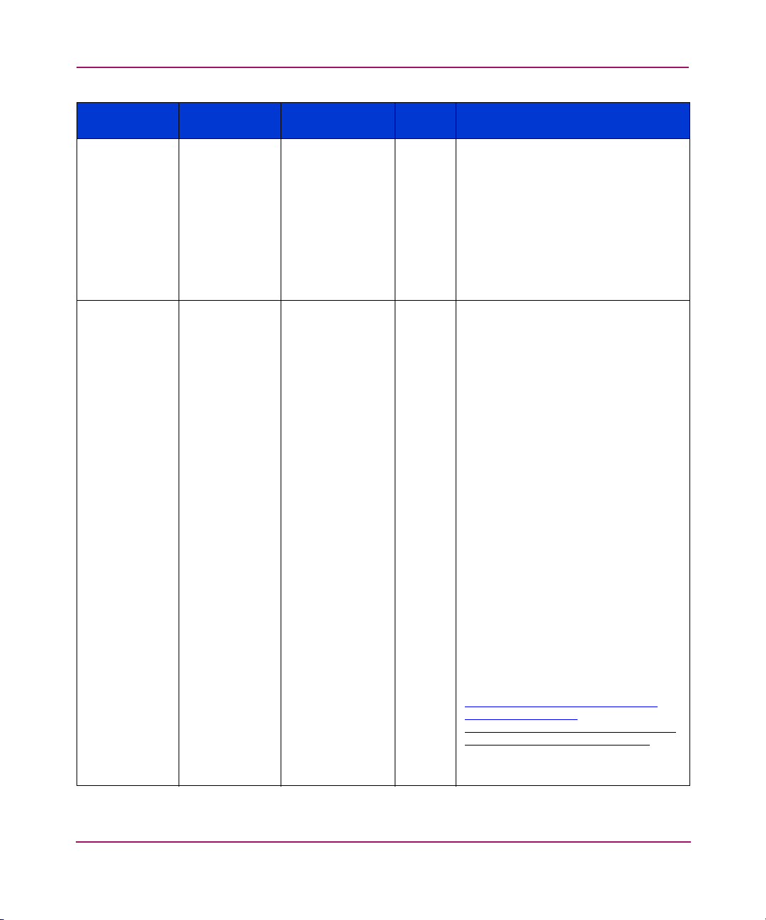
SNMP Support
FA MIB
Object Name Type
*fcConnUnitId OCTET
STRING
FcConnUnitGl
FcGlobalId Switch’s WWN. R
obalId
Product
Mapping Access Description
Switch’s WWN. R
The unique identification for this
connectivity unit among those within
this proxy domain. The value
unique within the proxy domain
because it is the index variable for
fcConnUnitTable. The value
assigned to a given connectivity unit
should be persistent across agent
and unit resets. It
as fcConnUnitGlobalId if
fcConnUnitGlobalId is known and
stable.
An optional global-scope identifier
for this connectivity unit. It
WWN for this connectivity unit or
16 octets of value zero.
WWN formats requiring fewer than
16 octets
must be extended to 16
octets with trailing zero octets. If a
WWN is used for fcConnUnitId, the
same WWN
must be used for
fcConnUnitGlobalId.
When a non-zero value is provided,
it
should be persistent across agent
and unit resets. It
unique. It
should be one of these
FC-PH/PH3 formats:
IEEE (NAA=1)
IEEE Extended (NAA=2)
IEEE Registered (NAA=5)
IEEE Registered extended (NAA=6)
must be
should be the same
must be a
should be globally
Use of the IEEE formats allows any
IEEE-registered vendor to assure
global uniqueness independently.
The following are some references
on IEEE WWN formats:
http://standards.ieee.org/regauth/oui/
tutorials/fibrefo rm at.html
http://standards.ieee.org/regauth/
oui/tutorials/fibrecomp_id.html
(continues in next cell)
89SNMP Reference for Directors and Edge Switches
Page 90

SNMP Support
FcConnUnitGl
obalId
(continued
from previous
cell)
FcGlobalId Switch’s WWN. R (continued from previous cell)
If one or more WWNs are
associated with the connectivity unit
via other management methods, one
of them
should be used for
fcConnUnitGlobalId. If there is not a
WWN assigned specifically to the
connectivity unit, there is some merit,
though not a requirement, to using a
WWN assigned to (one of) its
permanently attached FC/LAN
interface(s). This cannot risk
uniqueness, though. As a
counterexample, if your agent runs
in a host and the host has an HBA, it
is quite possible that agent, host,
and HBA will all be distinct
connectivity units, so the host and
agent cannot use the WWN of the
HBA. Another example: If your hub
has a built-in Ethernet port, it might
be reasonable for the hub to use its
LAN address (prefixed with the
appropriate NAA) as its
fcConnUnitId. But if the Ethernet is a
replaceable PC Card, the hub
should have an independent ID.
FcConnUnitTypeFcUnitType switch(4) R The type of this connectivity unit.
FcConnUnitN
umports
FcConnUnitSt
ate
Unsigned32 Number of ports
from
PROD_CNFG.
INTEGER online and
coming-online
will indicate
online state (2),
and offline and
going-offline
will indicate
offline state (3).
R Number of physical ports in the
connectivity unit
(internal/embedded, external).
R This object reports the overall state
of the connectivity unit. The meaning
of all values is essentially
self-explanatory. Any of these values
may occur with any of the
fcConnUnitStatus values.
The values are defined as follows:
unknown (1), online (2), offline (3).
90 SNMP Reference for Directors and Edge Switches
Page 91

SNMP Support
FcConnUnitSt
atus
INTEGER This value will
be mapped
from current
status of switch
in such a way
that operational
status indicates
ok (3),
degraded status
indicates
warning (4),
failed status
indicates failed
(5).
fcConnUnitPr
oduct
FcConnUnitSe
rialNo
FcConnUnitU
SnmpAdminSt
ring
SnmpAdminSt
ring
OEM product
name.
OEM serial
number.
TimeTicks R The number of centiseconds since
pTime
FcConnUnitUrlDisplayString Same as
fcConnURL.
FcConnUnitD
omainId
OCTET
STRING (SIZE
(3))
FFCCXX
XX is the active
domainId of the
switch.
FcConnUnitPr
INTEGER yes(3) R A value of "yes" means this is the
oxyMaster
R This object reports the overall status
of the connectivity unit. The warning
(4) value means that the connectivity
unit needs attention; all other values
are essentially self-explanatory. Any
of these values may occur with any
of the fcConnUnitState values.
The values are defined as follows:
unknown (1), unused (2), ok (3),
warning(4), failed (5)
R The connectivity unit vendor’s
product model name.
R The serial number identification for
this connectivity unit.
the last unit initialization.
R/W URL to launch a management
application, if applicable.
Otherwise, empty string. In a
standalone unit, this would be the
same as the top level URL. This has
the same definition as the system
URL for keywords.
R 24-bit Fibre Channel address ID of
this connectivity unit. Following the
Fibre Channel standard, the
right-most bit of the right-most octet
is for the least significant bit of the
address value; the left-most bit of the
left-most octet, if needed, is for the
most significant bit of the address
value. If this value is not applicable,
all bits are set to 1.
proxy master unit for a set of
managed units. For example, this
could be the only unit with a
management card in it for a set of
units. A standalone unit should
return "yes" for this object. The
values are defined as follows:
unknown (1), no (2), yes (3).
91SNMP Reference for Directors and Edge Switches
Page 92

SNMP Support
FcConnUnitPri
INTEGER R Whether this connectivity unit is the
ncipal
FcConnUnitN
Unsigned32 The number of
umSensors
FcConnUnitN
Unsigned32 1 R The number of revisions in the
umRevs
FcConnUnitM
oduleId
OCTET
STRING(SIZE(
16))
FcConnUnitN
ame
SnmpAdminSt
ring
FcConnUnitInfoSnmpAdminSt
ring
sensors.
Returns 16
zeros. (currently
not supported)
Switch’s
configured
name.
Writable and
persistent across
IPL.
Textual
description of
the product.
Writable and
persistent across
IPL.
principal unit within the group of
fabric elements. If this value is not
applicable, return unknown. The
values are defined as follows:
unknown (1), no (2), yes (3).
RNumber of sensors in the
fcConnUnitSensorTable.
fcConnUnitRevsTable.
R A unique id, persistent between
boots, that can be used to group a
set of connectivity units together into
a module. The intended use would
be to create a connectivity unit with
an fcConnUnitType of "module" to
represent a physical or logical
group of connectivity units. Then the
members of the group would set the
value of fcConnUnitId for this
"container" connectivity unit.
FcConnUnitModuleId should be
zeros if this connectivity unit is not
part of a module.
R/W A name for this connectivity unit.
This object value should be
persistent between boots.
R/W Information about this connectivity
unit. This object value should be
persistent between boots.
92 SNMP Reference for Directors and Edge Switches
Page 93

SNMP Support
FcConnUnitC
ontrol
INTEGER Always return
unknown (1) on
read operation.
ResetConnUnit
WarmStart (4),
offlineConnUnit
(5), and
onlineConnUnit
(6) will be
supported by
PCP.
ResetConnUnit
WarmStart (4)
indicates IPL on
the switch is
performed.
ResetConnUnitC
oldStart (3) is
not supported.
R/W Is used to control the addressed
connectivity unit.
NOTE: "ColdStart" and
"WarmStart" are as defined in
mib-2 and are not meant to be a
factory reset.
ResetConnUnitColdStart: the
addressed unit performs a
"ColdStart" reset.
ResetConnUnitWarmStart: the
addressed unit performs a
"WarmStart" reset.
OfflineConnUnit: the addressed unit
puts itself into an implementation
dependant "offline" state. In
general, if a unit is in an offline
state, it cannot be used to perform
meaningful Fibre Channel work.
OnlineConnUnit: the addressed unit
puts itself into an implementation
dependant "online" state. In
general, if a unit is in an online
state, it is capable of performing
meaningful Fibre Channel work.
NOTE: Each implementation may
choose not to support SNMP Set
operations for any or all of these
values. For Sets specifying varbinds
for instances of this object and
values not supported by a given
implementation, the agent will return
the SNMP WrongValue PDU error
code.
The values are defined as follows:
unknown (1), invalid (2),
resetConnUnitColdStart (3),
resetConnUnitWarmStart (4),
offlineConnUnit (5), onlineConnUnit
(6).
93SNMP Reference for Directors and Edge Switches
Page 94

SNMP Support
FcConnUnitC
ontact
FcConnUnitLo
cation
FcConnUnitEv
entFilter
FcConnUnitN
umEvents
FcConnUnitM
axEvents
FcConnUnitEv
entCurrID
SnmpAdminSt
ring
SnmpAdminSt
ring
Contact
information for
this connectivity
unit.
Writable and
persistent across
IPL.
The physical
location of the
R/W Contact information for this
connectivity unit. The contact
information is intended to facilitate
contacting someone in case of
problems, questions, and so forth.
(for example, the help desk internal
to a company).
R/W Location information for this
connectivity unit.
switch.
Writable and
persistent across
IPL.
FcEventSeverityWritable and it
is set to the
default value of
info(8) after IPL.
R/W Defines the event severity that will be
logged by this connectivity unit. All
events of severity less than or equal
to fcConnUnitEventFilter are logged
in the fcConnUnitEventTable.
Unsigned32 Number of
events in the
R Number of events currently in the
fcConnUnitEventTable.
fcConnUnitEvent
Table. It is
always <= 200,
the maximum
size of the event
table.
Unsigned32 200. R Max number of events that can be
recorded at any one time in the
fcConnUnitEventTable.
Unsigned32 The current
event index is
used as the last
used event id.
R
The last used event id
(fcConnUnitEventIndex) recorded in
the fcConnUnitEventTable. When no
events are presently recorded in the
fcConnUnitEventTable, the value of
this object
must be zero.
94 SNMP Reference for Directors and Edge Switches
Page 95

Firmware Table
The revisions table lists the revisions supported by the associated connectivity
units.
FA MIB
Object
Name
*fcConnUnitR
evsIndex
FcConnUnitRe
vsRevision
FcConnUnitRe
vsDescription
SNMP Support
Type Product Mapping Access Description
Unsigned32Not accessible R A unique value among
SnmpAd
minString
SnmpAd
minString
XX.XX.XX (The revision of the
switch).
Switch Firmware Level R Description of a
R A vendor-specific value
all fcConnUnitRevsEntrys
with the same value of
fcConnUnitId, in the
range between 1 and
fcConnUnitNumRevs[fcC
onnUnitId].
identifying a revision of
a component of the
connectivity unit.
component in the
fcConnUnit to which the
revision corresponds.
Sensor Table
The sensor table lists the sensors (for fan and power supplies) supported by each
switch. For each switch, the table will contain a list of all fan and power supply
FRU positions, regardless of whether they are installed. When a FRU is not
installed, the UnitSensorStatus for that table entry will be unknown(1). When a
power supply or fan FRU is installed or removed, a sensor trap will be sent (if
enabled), which contains an index to the appropriate entry in this table, for the
affected FRU. Note that the number of entries in the table does not change when a
fan/power supply FRU is installed or removed.
95SNMP Reference for Directors and Edge Switches
Page 96

SNMP Support
FA MIB
Object
Name
*fcConnUnitS
ensorIndex
FcConnUnitSe
nsorName
FcConnUnitSe
nsorStatus
FcConnUnitSe
nsorInfo
Type Product Mapping Access Description
Unsigned32Not assessable. R A unique value among
all
fcConnUnitSensorEntrys
with the same value of
fcConnUnitId, in the
range between 1 and
fcConnUnitNumSensors[f
cConnUnitId].
SnmpAd
minString
The module name of the FRU,
such as FAN, PWR or THM.
R A textual identification of
the sensor, intended
primarily for operator
use.
INTEGER This value is evaluated from
FRU status. The active, backup
and update-busy states are
mapped to ok(3). The failed
state is mapped to failed(5).
RThe status indicated by
the sensor. The values
are defined as follows:
unknown (1) – the unit
cannot determine the
status, other (2) -- the
status does not fit any of
the remaining values, ok
(3) – indicates good
status, warning (4) –
indicates the unit needs
attention, failed (5) B
indicates the unit is
non-functional.
SnmpAd
minString
The serial number of the FRUs.
This is not supported if the
module is failed.
R Miscellaneous static
information about the
sensor, such as its serial
number.
96 SNMP Reference for Directors and Edge Switches
Page 97

SNMP Support
FcConnUnitSe
nsorMessage
FcConnUnitSe
nsorType
FcConnUnitSe
nsorCharacter
istic
SnmpAd
minString
The textual description of the
FRU status, such as “active” or
“failed”.
R Describes the status of
the sensor as a message.
It may also provide more
resolution on the sensor
indication, for example
"Cover temperature
1503K, above nominal
operating range".
INTEGER Fan (4) or power-supply (5). R The type of component
being monitored by this
sensor. The unknown (1)
and other (2) value
meanings are analogous
to those for the
fcConnUnitSensorStatus
object; all other values
are essentially
self-explanatory.
The values are defined
as follows: unknown (1),
other (2), battery (3), fan
(4), powerSupply (5),
transmitter (6), enclosure
(7), board (8), and
receiver (9).
INTEGER Not supported. Always other
(2).
R The characteristics being
monitored by this sensor.
The unknown (1) and
other (2) value meanings
are analogous to those
for the
fcConnUnitSensorStatus
object; emf (5) refers to
electro-magnetic field; all
other values are
essentially
self-explanatory. The
values are defined as
follows: unknown (1),
other (2), temperature
(3), pressure (4), emf (5),
currentValue (6), airflow
(7), frequency (8), and
power (9).
97SNMP Reference for Directors and Edge Switches
Page 98

SNMP Support
Port Table
FA MIB
Object
Name
fcConnUnitPo
rtIndex
FcConnUnitPo
rtType
Generic information on ports for a specific fcConnUnit.
Type Product Mapping Access Description
Unsigned32Port index. R A unique value among all
fcConnUnitPortEntrys on this
connectivity unit, between 1
and fcConnUnitNumPorts.
INTEGER If the port is Not installed,
notPresent(3)
else if the Port State is
online, use the operating
Port Type:
F_Port = fPort(8)
FL_Port = flPort(7)
E_Port = ePort(9)
H_Port = hubPort(4)
B_Port = ePort(9)
else use the configured Port
Type:
Gx_Port = gPort(10)
G_Port = gPort(10)
Fx_Port = flPort(7)
F_Port = fPort(8)
E_Port = ePort(9)
RRefers to the protocol active
on the port and can take one
of the following values:
unknown (1) – cannot be
determined, other (2) – none
of the following, notPresent
(3) – no port, hubPort (4) –
hub port, nPort (5) – end port
for fabric, lPort (6) – end port
for loop, flPort (7) – public
loop, fPort (8) – fabric port,
ePort (9) – fabric expansion
port, gPort (10) – generic
fabric port,
domainController (1) –
domain controller,
hubController (12) – hub
controller, scsi (13) – parallel
SCSI port, escon (14) –
escon port, lan (15) – LAN
port, wan (16) – WAN port.
98 SNMP Reference for Directors and Edge Switches
Page 99

SNMP Support
FcConnUnitPo
rtFCClassCap
FcPortFC
Class
I f t h e p o r t i s n o t i n s t a l l e d ,
fcConnUnitPortFCClassCap
= 0
else if ES-1000
H_Port 0x18 =
class2(0x10) +
class3(0x08)
B_Port 0x58 = classF(0x40)
+ class2(0x10) +
class3(0x08)
else depends on the
configured Port Type:
Gx_Port 0x58 =
classF(0x40) +
class2(0x10) +
class3(0x08)
G_Port 0x58 =
classF(0x40) +
class2(0x10) +
class3(0x08)
Fx_Port 0x18 =
class2(0x10) +
class3(0x08)
F_Port 0x18 =
class2(0x10) +
class3(0x08)
E_Port 0x58 = classF(0x40)
+ class2(0x10) +
class3(0x08)
R
Bit mask that specifies the
classes of service capability
of this port. If this object is
not applicable, the agent
must return all bits set to
zero.
99SNMP Reference for Directors and Edge Switches
Page 100

SNMP Support
FcConnUnitPo
rtFCClassOp
FcConnUnitPo
rtState
FcPortFC
Class
If the port is Not installed
fcConnUnitPortFCClassOp
= 0
else if the Port State is
offline
fcConnUnitPortFCClassOp
= 0
else it depends on the
operating Port Type:
F_Port Use Class of Service
specified in Fabric Login
FL_Port Use Class of
Service specified in one or
more Fabric Login's (OR'd
together)
E_Port 0x58 = classF(0x40)
+ class2(0x10) +
class3(0x08)
INTEGER See “Port State
Descriptions” on
page 145.
R
Bit mask that specifies the
classes of service that are
currently operational at this
port. If this object is not
applicable, the agent
must
return all bits set to zero.
R The current state of the port
hardware. The bypassed
value (4) means that the port
is online but is currently
being isolated from the loop
or fabric for some reason;
the other values are
essentially self-explanatory.
Any value for this object may
co-exist with any value for
the fcConnUnitPortStatus
object. The values are
defined as follows: unknown
(1), online (2), offline (3),
bypassed (4).
100 SNMP Reference for Directors and Edge Switches
 Loading...