

Page 1

hp color LaserJet
4550/4500 series
service
manual
achieve
Page 2

Page 3

HP Color LaserJet 4550/4550N/4550DN/
4550HDN Printer and HP Color LaserJet 4500/
4500 N/4500 DN Printer
Service Manual _____________
Page 4

© Copyright 2000, Hewlett-Packard
Company
All Rights Reserved. Reproduction,
adaptation, or translation without prior written
permission is prohibited, except as allowed
under the copyright laws.
Part number: C7085-90921
First Edition, October 2000
Warranty
The information contained in this document is
subject to change without notice.
Hewlett-Packard makes no warranty of any
kind with respect to this information.
HEWLETT-PACKARD SPECIFICALLY
DISCLAIMS THE IMPLIED WARRANTY OF
MERCHANTABILITY AND FITNESS FOR A
PARTICULAR PURPOSE.
Hewlett-Packard shall not be liable for any
direct, indirect, incidental, consequential, or
other damage alleged in connection with the
furnishing or use of this information.
Trademark Credits
Adobe is a trademark of Adobe Systems
Incorporated which may be registered in
certain jurisdictions.
Arial is a U.S. registered trademark of the
Monotype Corporation.
TM
CompuServe
CompuServe, Inc.
NERGY STAR is a U.S. registered service
E
mark of the United States Environmental
Protection Agency.
Microsoft
Microsoft Corporation.
PANTONE
trademark for color.
PostScript is a trademark of Adobe Systems,
Incorporated, which may be registered in
certain jurisdictions.
TrueType is a U.S. trademark of Apple
Computer, Inc.
UNIX is a registered trademark in the United
States and other countries, licensed
exclusively through X/Open Company
Limited.
Windows, MS Windows, and Windows NT are
U.S. registered trademarks of Microsoft
Corporation.
is a U.S. trademark of
®
is a U.S. registered trademark of
®
Pantone, Inc.’s check-standard
Hewlett-Packard Company
11311 Chinden Boulevard
Boise, Idaho 83714 U.S.A.
Page 5

Conventions
This is a combined Service Manual for both the HP Color LaserJet 4500 series printer and the HP
Color LaserJet 4550 series printer. The HP Color LaserJet 4550 series printer shares most
characteristics of the HP Color LaserJet 4500 series printer, except where stated.
This manual uses the following conventions:
OLoR is used to emphasize items that are important to the material under discussion.
C
Bold is used for emphasis, particularly in situations where italic type would be confusing.
Italic type is used to indicate related documents or emphasis.
DISPLAY type indicates text as seen on the printer control panel display.
Commands you use on a computer keyboard or on the printer control panel are shown in
[Keycap]. Two examples are [Select], and
[-[Value +].
COURIER type indicates text that you type on a computer keyboard exactly as shown.
Hint Hints are used to suggest an action that might simplify the process.
WWW World Wide Web ref erences give Internet addresses for additional information and information updates.
Note Notes contain important information set off from the text.
CAUTION Caution messages alert you to the possibility of damage to equipment or loss of data.
WARNING! Warning messages alert you to the possibility of personal injury.
iii
Page 6

iv
Page 7

Contents
1 Printer description
Printer features . . . . . . . . . . . . . . . . . . . . . . . . . . . . . . . . . . . . . . . . . . . . . . . . . . . . . . . . . . . . . . . . . . . . . . . . .14
Identification . . . . . . . . . . . . . . . . . . . . . . . . . . . . . . . . . . . . . . . . . . . . . . . . . . . . . . . . . . . . . . . . . . . . . . . . . . .18
Site requirements . . . . . . . . . . . . . . . . . . . . . . . . . . . . . . . . . . . . . . . . . . . . . . . . . . . . . . . . . . . . . . . . . . . . . . .20
Printer specifications. . . . . . . . . . . . . . . . . . . . . . . . . . . . . . . . . . . . . . . . . . . . . . . . . . . . . . . . . . . . . . . . . . . . .23
Printer assemblies. . . . . . . . . . . . . . . . . . . . . . . . . . . . . . . . . . . . . . . . . . . . . . . . . . . . . . . . . . . . . . . . . . . . . . .25
Media requirements. . . . . . . . . . . . . . . . . . . . . . . . . . . . . . . . . . . . . . . . . . . . . . . . . . . . . . . . . . . . . . . . . . . . . .28
Environmental Product Stewardship Program . . . . . . . . . . . . . . . . . . . . . . . . . . . . . . . . . . . . . . . . . . . . . . . . .34
Regulatory statements . . . . . . . . . . . . . . . . . . . . . . . . . . . . . . . . . . . . . . . . . . . . . . . . . . . . . . . . . . . . . . . . . . .36
Safety information . . . . . . . . . . . . . . . . . . . . . . . . . . . . . . . . . . . . . . . . . . . . . . . . . . . . . . . . . . . . . . . . . . . . . . .37
2 Service approach
Service approach . . . . . . . . . . . . . . . . . . . . . . . . . . . . . . . . . . . . . . . . . . . . . . . . . . . . . . . . . . . . . . . . . . . . . . .40
Parts and supplies. . . . . . . . . . . . . . . . . . . . . . . . . . . . . . . . . . . . . . . . . . . . . . . . . . . . . . . . . . . . . . . . . . . . . . .41
Warranty statement. . . . . . . . . . . . . . . . . . . . . . . . . . . . . . . . . . . . . . . . . . . . . . . . . . . . . . . . . . . . . . . . . . . . . .44
3 Installation and configuration
Unpack the printer. . . . . . . . . . . . . . . . . . . . . . . . . . . . . . . . . . . . . . . . . . . . . . . . . . . . . . . . . . . . . . . . . . . . . . .48
Installation. . . . . . . . . . . . . . . . . . . . . . . . . . . . . . . . . . . . . . . . . . . . . . . . . . . . . . . . . . . . . . . . . . . . . . . . . . . . .50
Connecting to a network . . . . . . . . . . . . . . . . . . . . . . . . . . . . . . . . . . . . . . . . . . . . . . . . . . . . . . . . . . . . . . . . . .64
Enhanced I/O (EIO) configuration . . . . . . . . . . . . . . . . . . . . . . . . . . . . . . . . . . . . . . . . . . . . . . . . . . . . . . . . . .67
Printer drivers . . . . . . . . . . . . . . . . . . . . . . . . . . . . . . . . . . . . . . . . . . . . . . . . . . . . . . . . . . . . . . . . . . . . . . . . . .69
Network configuration . . . . . . . . . . . . . . . . . . . . . . . . . . . . . . . . . . . . . . . . . . . . . . . . . . . . . . . . . . . . . . . . . . . .70
Configuration tips . . . . . . . . . . . . . . . . . . . . . . . . . . . . . . . . . . . . . . . . . . . . . . . . . . . . . . . . . . . . . . . . . . . . . . .71
Setting network security on the printer . . . . . . . . . . . . . . . . . . . . . . . . . . . . . . . . . . . . . . . . . . . . . . . . . . . . . . .73
4 Printer maintenance
Cleaning the printer and accessories . . . . . . . . . . . . . . . . . . . . . . . . . . . . . . . . . . . . . . . . . . . . . . . . . . . . . . . .78
Approximate replacement intervals for consumable items . . . . . . . . . . . . . . . . . . . . . . . . . . . . . . . . . . . . . . . .80
Locating consumables. . . . . . . . . . . . . . . . . . . . . . . . . . . . . . . . . . . . . . . . . . . . . . . . . . . . . . . . . . . . . . . . . . . .84
Replacing consumable items . . . . . . . . . . . . . . . . . . . . . . . . . . . . . . . . . . . . . . . . . . . . . . . . . . . . . . . . . . . . . .85
DIMM configuration. . . . . . . . . . . . . . . . . . . . . . . . . . . . . . . . . . . . . . . . . . . . . . . . . . . . . . . . . . . . . . . . . . . . . .98
5 Theory of operation
Introduction . . . . . . . . . . . . . . . . . . . . . . . . . . . . . . . . . . . . . . . . . . . . . . . . . . . . . . . . . . . . . . . . . . . . . . . . . . .102
Basic operation . . . . . . . . . . . . . . . . . . . . . . . . . . . . . . . . . . . . . . . . . . . . . . . . . . . . . . . . . . . . . . . . . . . . . . . .103
Image formation . . . . . . . . . . . . . . . . . . . . . . . . . . . . . . . . . . . . . . . . . . . . . . . . . . . . . . . . . . . . . . . . . . . . . . .104
Toner density. . . . . . . . . . . . . . . . . . . . . . . . . . . . . . . . . . . . . . . . . . . . . . . . . . . . . . . . . . . . . . . . . . . . . . . . . .111
Mechanical system . . . . . . . . . . . . . . . . . . . . . . . . . . . . . . . . . . . . . . . . . . . . . . . . . . . . . . . . . . . . . . . . . . . . .112
Paper path. . . . . . . . . . . . . . . . . . . . . . . . . . . . . . . . . . . . . . . . . . . . . . . . . . . . . . . . . . . . . . . . . . . . . . . . . . . .122
DC controller subsystem. . . . . . . . . . . . . . . . . . . . . . . . . . . . . . . . . . . . . . . . . . . . . . . . . . . . . . . . . . . . . . . . .132
Motors and fans. . . . . . . . . . . . . . . . . . . . . . . . . . . . . . . . . . . . . . . . . . . . . . . . . . . . . . . . . . . . . . . . . . . . . . . .133
Formatter system . . . . . . . . . . . . . . . . . . . . . . . . . . . . . . . . . . . . . . . . . . . . . . . . . . . . . . . . . . . . . . . . . . . . . .135
Power supplies . . . . . . . . . . . . . . . . . . . . . . . . . . . . . . . . . . . . . . . . . . . . . . . . . . . . . . . . . . . . . . . . . . . . . . . .135
Contents v
Page 8

6 Removal and replacement
Introduction. . . . . . . . . . . . . . . . . . . . . . . . . . . . . . . . . . . . . . . . . . . . . . . . . . . . . . . . . . . . . . . . . . . . . . . . . . . 139
Consumable assemblies . . . . . . . . . . . . . . . . . . . . . . . . . . . . . . . . . . . . . . . . . . . . . . . . . . . . . . . . . . . . . . . . 142
Covers, drawers, and top and front assemblies. . . . . . . . . . . . . . . . . . . . . . . . . . . . . . . . . . . . . . . . . . . . . . . 144
Right side assemblies. . . . . . . . . . . . . . . . . . . . . . . . . . . . . . . . . . . . . . . . . . . . . . . . . . . . . . . . . . . . . . . . . . . 168
Left side assemblies. . . . . . . . . . . . . . . . . . . . . . . . . . . . . . . . . . . . . . . . . . . . . . . . . . . . . . . . . . . . . . . . . . . . 182
Rear assemblies. . . . . . . . . . . . . . . . . . . . . . . . . . . . . . . . . . . . . . . . . . . . . . . . . . . . . . . . . . . . . . . . . . . . . . . 195
Internal assemblies. . . . . . . . . . . . . . . . . . . . . . . . . . . . . . . . . . . . . . . . . . . . . . . . . . . . . . . . . . . . . . . . . . . . . 200
7 Troubleshooting
Introduction. . . . . . . . . . . . . . . . . . . . . . . . . . . . . . . . . . . . . . . . . . . . . . . . . . . . . . . . . . . . . . . . . . . . . . . . . . . 211
Troubleshooting process . . . . . . . . . . . . . . . . . . . . . . . . . . . . . . . . . . . . . . . . . . . . . . . . . . . . . . . . . . . . . . . . 212
Printer error troubleshooting. . . . . . . . . . . . . . . . . . . . . . . . . . . . . . . . . . . . . . . . . . . . . . . . . . . . . . . . . . . . . . 217
Paper path troubleshooting . . . . . . . . . . . . . . . . . . . . . . . . . . . . . . . . . . . . . . . . . . . . . . . . . . . . . . . . . . . . . . 237
Image formation troubleshooting . . . . . . . . . . . . . . . . . . . . . . . . . . . . . . . . . . . . . . . . . . . . . . . . . . . . . . . . . . 243
HP ColorSmart II . . . . . . . . . . . . . . . . . . . . . . . . . . . . . . . . . . . . . . . . . . . . . . . . . . . . . . . . . . . . . . . . . . . . . . 246
Matching colors . . . . . . . . . . . . . . . . . . . . . . . . . . . . . . . . . . . . . . . . . . . . . . . . . . . . . . . . . . . . . . . . . . . . . . . 247
Four-color printing (CMYK). . . . . . . . . . . . . . . . . . . . . . . . . . . . . . . . . . . . . . . . . . . . . . . . . . . . . . . . . . . . . . . 248
Image defects . . . . . . . . . . . . . . . . . . . . . . . . . . . . . . . . . . . . . . . . . . . . . . . . . . . . . . . . . . . . . . . . . . . . . . . . 253
Overhead transparency defects . . . . . . . . . . . . . . . . . . . . . . . . . . . . . . . . . . . . . . . . . . . . . . . . . . . . . . . . . . 263
Repetitive defects troubleshooting . . . . . . . . . . . . . . . . . . . . . . . . . . . . . . . . . . . . . . . . . . . . . . . . . . . . . . . . . 265
Interface troubleshooting . . . . . . . . . . . . . . . . . . . . . . . . . . . . . . . . . . . . . . . . . . . . . . . . . . . . . . . . . . . . . . . .268
Control panel troubleshooting. . . . . . . . . . . . . . . . . . . . . . . . . . . . . . . . . . . . . . . . . . . . . . . . . . . . . . . . . . . . . 271
Troubleshooting tools. . . . . . . . . . . . . . . . . . . . . . . . . . . . . . . . . . . . . . . . . . . . . . . . . . . . . . . . . . . . . . . . . . . 285
Service mode . . . . . . . . . . . . . . . . . . . . . . . . . . . . . . . . . . . . . . . . . . . . . . . . . . . . . . . . . . . . . . . . . . . . . . . . . 293
Diagnostics mode . . . . . . . . . . . . . . . . . . . . . . . . . . . . . . . . . . . . . . . . . . . . . . . . . . . . . . . . . . . . . . . . . . . . .300
Diagrams . . . . . . . . . . . . . . . . . . . . . . . . . . . . . . . . . . . . . . . . . . . . . . . . . . . . . . . . . . . . . . . . . . . . . . . . . . . . 308
8 Parts and diagrams
Introduction. . . . . . . . . . . . . . . . . . . . . . . . . . . . . . . . . . . . . . . . . . . . . . . . . . . . . . . . . . . . . . . . . . . . . . . . . . . 324
Ordering parts. . . . . . . . . . . . . . . . . . . . . . . . . . . . . . . . . . . . . . . . . . . . . . . . . . . . . . . . . . . . . . . . . . . . . . . . . 325
Illustrations and parts lists . . . . . . . . . . . . . . . . . . . . . . . . . . . . . . . . . . . . . . . . . . . . . . . . . . . . . . . . . . . . . . . 329
Alphabetical parts list . . . . . . . . . . . . . . . . . . . . . . . . . . . . . . . . . . . . . . . . . . . . . . . . . . . . . . . . . . . . . . . . . . . 355
Numerical parts list. . . . . . . . . . . . . . . . . . . . . . . . . . . . . . . . . . . . . . . . . . . . . . . . . . . . . . . . . . . . . . . . . . . . . 359
vi
Page 9

List of Figures
Figure 1-1 HP Color LaserJet 4500 family printers . . . . . . . . . . . . . . . . . . . . . . . . . . . . . . . . . . . . . . . . . . . . .14
Figure 1-2 HP Color LaserJet 4550 series printers . . . . . . . . . . . . . . . . . . . . . . . . . . . . . . . . . . . . . . . . . . . . .15
Figure 1-3 Model and Serial number information . . . . . . . . . . . . . . . . . . . . . . . . . . . . . . . . . . . . . . . . . . . . . .18
Figure 1-4 Sample label . . . . . . . . . . . . . . . . . . . . . . . . . . . . . . . . . . . . . . . . . . . . . . . . . . . . . . . . . . . . . . . . .19
Figure 1-5 Space requirements . . . . . . . . . . . . . . . . . . . . . . . . . . . . . . . . . . . . . . . . . . . . . . . . . . . . . . . . . . . .21
Figure 1-6 Front view, HP Color LaserJet 4500 and HP Color LaserJet 4550
(shown with 500-sheet paper feeder and duplex unit) . . . . . . . . . . . . . . . . . . . . . . . . . . . . . . . . . . . . . . . .25
Figure 1-7 Rear view, HP Color LaserJet 4500 (shown with 500-sheet paper feeder and duplex unit) . . . . .26
Figure 1-8 Rear view, HP Color LaserJet 4550 (shown with 500-sheet paper feeder and duplex unit) . . . . .27
Figure 3-1 Package contents . . . . . . . . . . . . . . . . . . . . . . . . . . . . . . . . . . . . . . . . . . . . . . . . . . . . . . . . . . . . .48
Figure 3-2 Parallel cable with a “C” connector . . . . . . . . . . . . . . . . . . . . . . . . . . . . . . . . . . . . . . . . . . . . . . . .58
Figure 4-1 Imaging drum life . . . . . . . . . . . . . . . . . . . . . . . . . . . . . . . . . . . . . . . . . . . . . . . . . . . . . . . . . . . . . .81
Figure 4-2 OPC life . . . . . . . . . . . . . . . . . . . . . . . . . . . . . . . . . . . . . . . . . . . . . . . . . . . . . . . . . . . . . . . . . . . . .82
Figure 4-3 Location of consumables . . . . . . . . . . . . . . . . . . . . . . . . . . . . . . . . . . . . . . . . . . . . . . . . . . . . . . . .84
Figure 4-4 Removing the formatter board . . . . . . . . . . . . . . . . . . . . . . . . . . . . . . . . . . . . . . . . . . . . . . . . . . . .98
Figure 4-5 Do not remove the DIMM in slot #4. . . . . . . . . . . . . . . . . . . . . . . . . . . . . . . . . . . . . . . . . . . . . . . .99
Figure 4-6 Do not remove the DIMM in slot #3. . . . . . . . . . . . . . . . . . . . . . . . . . . . . . . . . . . . . . . . . . . . . . . .99
Figure 4-7 EDO and SDRAM memory modules . . . . . . . . . . . . . . . . . . . . . . . . . . . . . . . . . . . . . . . . . . . . . . .99
Figure 5-1 Basic system operation . . . . . . . . . . . . . . . . . . . . . . . . . . . . . . . . . . . . . . . . . . . . . . . . . . . . . . . .103
Figure 5-2 Image formation . . . . . . . . . . . . . . . . . . . . . . . . . . . . . . . . . . . . . . . . . . . . . . . . . . . . . . . . . . . . . .104
Figure 5-3 Primary charge . . . . . . . . . . . . . . . . . . . . . . . . . . . . . . . . . . . . . . . . . . . . . . . . . . . . . . . . . . . . . . .105
Figure 5-4 Laser exposure . . . . . . . . . . . . . . . . . . . . . . . . . . . . . . . . . . . . . . . . . . . . . . . . . . . . . . . . . . . . . .106
Figure 5-5 Development . . . . . . . . . . . . . . . . . . . . . . . . . . . . . . . . . . . . . . . . . . . . . . . . . . . . . . . . . . . . . . . .106
Figure 5-6 Primary transfer . . . . . . . . . . . . . . . . . . . . . . . . . . . . . . . . . . . . . . . . . . . . . . . . . . . . . . . . . . . . . .107
Figure 5-7 Secondary transfer . . . . . . . . . . . . . . . . . . . . . . . . . . . . . . . . . . . . . . . . . . . . . . . . . . . . . . . . . . . .108
Figure 5-8 Separation . . . . . . . . . . . . . . . . . . . . . . . . . . . . . . . . . . . . . . . . . . . . . . . . . . . . . . . . . . . . . . . . . .108
Figure 5-9 ITB residual toner cleaning . . . . . . . . . . . . . . . . . . . . . . . . . . . . . . . . . . . . . . . . . . . . . . . . . . . . .109
Figure 5-10 Waste toner to waste toner reservoir . . . . . . . . . . . . . . . . . . . . . . . . . . . . . . . . . . . . . . . . . . . . .109
Figure 5-11 Fuser . . . . . . . . . . . . . . . . . . . . . . . . . . . . . . . . . . . . . . . . . . . . . . . . . . . . . . . . . . . . . . . . . . . . .110
Figure 5-12 Toner density sensor . . . . . . . . . . . . . . . . . . . . . . . . . . . . . . . . . . . . . . . . . . . . . . . . . . . . . . . . .111
Figure 5-13 Photosensitive drum cartridge . . . . . . . . . . . . . . . . . . . . . . . . . . . . . . . . . . . . . . . . . . . . . . . . . .112
Figure 5-14 Waste toner . . . . . . . . . . . . . . . . . . . . . . . . . . . . . . . . . . . . . . . . . . . . . . . . . . . . . . . . . . . . . . . .113
Figure 5-15 Transfer unit function . . . . . . . . . . . . . . . . . . . . . . . . . . . . . . . . . . . . . . . . . . . . . . . . . . . . . . . . .113
Figure 5-16 Home position detection . . . . . . . . . . . . . . . . . . . . . . . . . . . . . . . . . . . . . . . . . . . . . . . . . . . . . .114
Figure 5-17 ITB unit life detection . . . . . . . . . . . . . . . . . . . . . . . . . . . . . . . . . . . . . . . . . . . . . . . . . . . . . . . . .115
Figure 5-18 Secondary transfer roller unit . . . . . . . . . . . . . . . . . . . . . . . . . . . . . . . . . . . . . . . . . . . . . . . . . . .116
Figure 5-19 ITB unit contact/separation unit . . . . . . . . . . . . . . . . . . . . . . . . . . . . . . . . . . . . . . . . . . . . . . . . .117
Figure 5-20 Toner carousel assembly . . . . . . . . . . . . . . . . . . . . . . . . . . . . . . . . . . . . . . . . . . . . . . . . . . . . . .118
Figure 5-21 Toner carousel operation . . . . . . . . . . . . . . . . . . . . . . . . . . . . . . . . . . . . . . . . . . . . . . . . . . . . . .119
Figure 5-22 Toner cartridge contact/separation function . . . . . . . . . . . . . . . . . . . . . . . . . . . . . . . . . . . . . . . .119
Figure 5-23 Toner level detection/toner cartridge detection . . . . . . . . . . . . . . . . . . . . . . . . . . . . . . . . . . . . .120
Figure 5-24 Laser/scanner operation . . . . . . . . . . . . . . . . . . . . . . . . . . . . . . . . . . . . . . . . . . . . . . . . . . . . . .121
Figure 5-25 Paper jam sensors (shown with the optional 500-sheet paper feeder and duplex
unit installed) . . . . . . . . . . . . . . . . . . . . . . . . . . . . . . . . . . . . . . . . . . . . . . . . . . . . . . . . . . . . . . . . . . . . . .122
Figure 5-26 Tray 2 (cassette) operation . . . . . . . . . . . . . . . . . . . . . . . . . . . . . . . . . . . . . . . . . . . . . . . . . . . .123
Figure 5-27 Tray 1 manual feed . . . . . . . . . . . . . . . . . . . . . . . . . . . . . . . . . . . . . . . . . . . . . . . . . . . . . . . . . .124
Figure 5-28 Laser paper detected . . . . . . . . . . . . . . . . . . . . . . . . . . . . . . . . . . . . . . . . . . . . . . . . . . . . . . . . .125
Figure 5-29 Overhead transparency sensor . . . . . . . . . . . . . . . . . . . . . . . . . . . . . . . . . . . . . . . . . . . . . . . . .125
Figure 5-30 Pick-up and feed system . . . . . . . . . . . . . . . . . . . . . . . . . . . . . . . . . . . . . . . . . . . . . . . . . . . . . .126
Figure 5-31 Fusing and delivery unit . . . . . . . . . . . . . . . . . . . . . . . . . . . . . . . . . . . . . . . . . . . . . . . . . . . . . . .127
Figure 5-32 Reversing and duplex pick-up operation . . . . . . . . . . . . . . . . . . . . . . . . . . . . . . . . . . . . . . . . . .128
Figure 5-33 Reversing operation . . . . . . . . . . . . . . . . . . . . . . . . . . . . . . . . . . . . . . . . . . . . . . . . . . . . . . . . . .129
Contents vii
Page 10

Figure 5-34 Side registration adjustment . . . . . . . . . . . . . . . . . . . . . . . . . . . . . . . . . . . . . . . . . . . . . . . . . . . 130
Figure 5-35 Duplex feed roller pressure . . . . . . . . . . . . . . . . . . . . . . . . . . . . . . . . . . . . . . . . . . . . . . . . . . . . 130
Figure 5-36 DC controller PCB . . . . . . . . . . . . . . . . . . . . . . . . . . . . . . . . . . . . . . . . . . . . . . . . . . . . . . . . . . . 132
Figure 5-37 Motors and fans . . . . . . . . . . . . . . . . . . . . . . . . . . . . . . . . . . . . . . . . . . . . . . . . . . . . . . . . . . . . 133
Figure 6-1 Phillips and Posidriv screwdriver comparison . . . . . . . . . . . . . . . . . . . . . . . . . . . . . . . . . . . . . . . 140
Figure 6-2 Top cover removal and replacement (rear view of printer) . . . . . . . . . . . . . . . . . . . . . . . . . . . . . 144
Figure 6-3 Left side cover removal and replacement . . . . . . . . . . . . . . . . . . . . . . . . . . . . . . . . . . . . . . . . . . 145
Figure 6-4 Right side cover removal and replacement . . . . . . . . . . . . . . . . . . . . . . . . . . . . . . . . . . . . . . . . . 146
Figure 6-5 Rear door removal and replacement . . . . . . . . . . . . . . . . . . . . . . . . . . . . . . . . . . . . . . . . . . . . . . 147
Figure 6-6 Right rear cover removal and replacement . . . . . . . . . . . . . . . . . . . . . . . . . . . . . . . . . . . . . . . . . 148
Figure 6-7 Drum drawer (top drawer) cover removal and replacement . . . . . . . . . . . . . . . . . . . . . . . . . . . . 149
Figure 6-8 Drum drawer (top drawer) cover tabs and levers . . . . . . . . . . . . . . . . . . . . . . . . . . . . . . . . . . . . 150
Figure 6-9 ITB drawer (middle drawer) cover removal and replacement . . . . . . . . . . . . . . . . . . . . . . . . . . . 151
Figure 6-10 ITB drawer (middle drawer) removal and replacement . . . . . . . . . . . . . . . . . . . . . . . . . . . . . . . 152
Figure 6-11 Control panel removal and replacement . . . . . . . . . . . . . . . . . . . . . . . . . . . . . . . . . . . . . . . . . . 153
Figure 6-12 Front right cover removal and replacement . . . . . . . . . . . . . . . . . . . . . . . . . . . . . . . . . . . . . . . 155
Figure 6-13 RFI shield removal and replacement . . . . . . . . . . . . . . . . . . . . . . . . . . . . . . . . . . . . . . . . . . . . 156
Figure 6-14 Laser/scanner assembly removal and replacement . . . . . . . . . . . . . . . . . . . . . . . . . . . . . . . . . 157
Figure 6-15 DC controller removal and replacement . . . . . . . . . . . . . . . . . . . . . . . . . . . . . . . . . . . . . . . . . . 158
Figure 6-16 Developing PCB removal and replacement (1 of 2) . . . . . . . . . . . . . . . . . . . . . . . . . . . . . . . . . 159
Figure 6-17 Developing PCB removal and replacement (2 of 2) . . . . . . . . . . . . . . . . . . . . . . . . . . . . . . . . . 160
Figure 6-18 Top cover switch assembly removal and replacement . . . . . . . . . . . . . . . . . . . . . . . . . . . . . . . 162
Figure 6-19 Top cover switch assembly removal and replacement . . . . . . . . . . . . . . . . . . . . . . . . . . . . . . . 162
Figure 6-20 Drum drawer (top drawer) switch . . . . . . . . . . . . . . . . . . . . . . . . . . . . . . . . . . . . . . . . . . . . . . . 163
Figure 6-21 Drum drawer (top drawer) assembly removal and replacement (1 of 3) . . . . . . . . . . . . . . . . . . 164
Figure 6-22 Drum drawer (top drawer) assembly removal and replacement (2 of 3) . . . . . . . . . . . . . . . . . . 165
Figure 6-23 Drum drawer assembly removal and replacement (3 of 3) . . . . . . . . . . . . . . . . . . . . . . . . . . . 165
Figure 6-24 Densitometer removal and replacement (1 of 2) . . . . . . . . . . . . . . . . . . . . . . . . . . . . . . . . . . . . 166
Figure 6-25 Densitometer removal and replacement (2 of 2) . . . . . . . . . . . . . . . . . . . . . . . . . . . . . . . . . . . . 167
Figure 6-26 Formatter removal and replacement . . . . . . . . . . . . . . . . . . . . . . . . . . . . . . . . . . . . . . . . . . . . . 168
Figure 6-27 Formatter pan assembly removal and replacement (1 of 4) . . . . . . . . . . . . . . . . . . . . . . . . . . . 170
Figure 6-28 Formatter pan assembly removal and replacement (2 of 4) . . . . . . . . . . . . . . . . . . . . . . . . . . . 171
Figure 6-29 Formatter pan assembly removal and replacement (3 of 4) . . . . . . . . . . . . . . . . . . . . . . . . . . . 171
Figure 6-30 Formatter pan assembly removal and replacement (4 of 4) . . . . . . . . . . . . . . . . . . . . . . . . . . . 172
Figure 6-31 Power supply removal and replacement . . . . . . . . . . . . . . . . . . . . . . . . . . . . . . . . . . . . . . . . . . 173
Figure 6-32 High-voltage power supply removal and replacement (newer version
HP Color LaserJet 4500 and HP Color LaserJet 4550 printers) . . . . . . . . . . . . . . . . . . . . . . . . . . . . . . . 174
Figure 6-33 High-voltage power supply removal and replacement (older version
HP Color LaserJet 4500 printers) . . . . . . . . . . . . . . . . . . . . . . . . . . . . . . . . . . . . . . . . . . . . . . . . . . . . . . 175
Figure 6-34 Drum drive assembly removal and replacement (1 of 3) . . . . . . . . . . . . . . . . . . . . . . . . . . . . . 176
Figure 6-35 Drum drive assembly removal and replacement (2 of 3) . . . . . . . . . . . . . . . . . . . . . . . . . . . . . 177
Figure 6-36 Drum drive assembly removal and replacement (3 of 3) . . . . . . . . . . . . . . . . . . . . . . . . . . . . . 177
Figure 6-37 Large fan removal and replacement (1 of 2) . . . . . . . . . . . . . . . . . . . . . . . . . . . . . . . . . . . . . . . 178
Figure 6-38 Large fan removal and replacement (2 of 2) . . . . . . . . . . . . . . . . . . . . . . . . . . . . . . . . . . . . . . . 178
Figure 6-39 Toner level sensor assembly removal and replacement . . . . . . . . . . . . . . . . . . . . . . . . . . . . . . 179
Figure 6-40 Carousel drive assembly removal and replacement (1 of 2) . . . . . . . . . . . . . . . . . . . . . . . . . . . 180
Figure 6-41 Carousel drive assembly removal and replacement (2 of 2) . . . . . . . . . . . . . . . . . . . . . . . . . . . 180
Figure 6-42 Paper size switch removal and replacement . . . . . . . . . . . . . . . . . . . . . . . . . . . . . . . . . . . . . . . 181
Figure 6-43 Switch plate assembly removal and replacement . . . . . . . . . . . . . . . . . . . . . . . . . . . . . . . . . . . 182
Figure 6-44 Paper feed PCB removal and replacement (1 of 3) . . . . . . . . . . . . . . . . . . . . . . . . . . . . . . . . . 183
Figure 6-45 Paper feed PCB removal and replacement (2 of 3) . . . . . . . . . . . . . . . . . . . . . . . . . . . . . . . . . 183
Figure 6-46 Paper feed PCB removal and replacement (3 of 3) . . . . . . . . . . . . . . . . . . . . . . . . . . . . . . . . . 184
Figure 6-47 Fuser motor removal and replacement (1 of 2) . . . . . . . . . . . . . . . . . . . . . . . . . . . . . . . . . . . . . 185
Figure 6-48 Fuser motor removal and replacement (2 of 2) . . . . . . . . . . . . . . . . . . . . . . . . . . . . . . . . . . . . . 186
Figure 6-49 Paper path motor removal and replacement . . . . . . . . . . . . . . . . . . . . . . . . . . . . . . . . . . . . . . . 187
Figure 6-50 Paper pick solenoid removal and replacement . . . . . . . . . . . . . . . . . . . . . . . . . . . . . . . . . . . . . 188
Figure 6-51 ITB cleaning roller clutch removal and replacement . . . . . . . . . . . . . . . . . . . . . . . . . . . . . . . . . 189
Figure 6-52 ITB clutch assembly removal and replacement (1 of 2) . . . . . . . . . . . . . . . . . . . . . . . . . . . . . . 190
Figure 6-53 ITB clutch assembly removal and replacement (2 of 2) . . . . . . . . . . . . . . . . . . . . . . . . . . . . . . 190
viii
Page 11

Figure 6-54 Transfer roller cam clutch removal and replacement . . . . . . . . . . . . . . . . . . . . . . . . . . . . . . . . .192
Figure 6-55 Left side gears removal and replacement (1 of 2) . . . . . . . . . . . . . . . . . . . . . . . . . . . . . . . . . . .194
Figure 6-56 Left side gears removal and replacement (2 of 2) . . . . . . . . . . . . . . . . . . . . . . . . . . . . . . . . . . .194
Figure 6-57 Large right side fan removal and replacement (1 of 2) . . . . . . . . . . . . . . . . . . . . . . . . . . . . . . .195
Figure 6-58 Large right side fan removal and replacement (2 of 2) . . . . . . . . . . . . . . . . . . . . . . . . . . . . . . .196
Figure 6-59 Left side fan removal and replacement (1 of 3) . . . . . . . . . . . . . . . . . . . . . . . . . . . . . . . . . . . . .197
Figure 6-60 Left side fan removal and replacement (2 of 3) . . . . . . . . . . . . . . . . . . . . . . . . . . . . . . . . . . . . .198
Figure 6-61 Left side fan removal and replacement (3 of 3) . . . . . . . . . . . . . . . . . . . . . . . . . . . . . . . . . . . . .198
Figure 6-62 Rear paper path assembly removal and replacement . . . . . . . . . . . . . . . . . . . . . . . . . . . . . . . .199
Figure 6-63 Cartridge carousel replacement - formatter pan assembly (1 of 6) . . . . . . . . . . . . . . . . . . . . . .200
Figure 6-64 Cartridge carousel replacement - continuous toner level sensor assembly (2 of 6) . . . . . . . . .201
Figure 6-65 Cartridge carousel replacement - carousel brake (3 of 6) . . . . . . . . . . . . . . . . . . . . . . . . . . . . .201
Figure 6-66 Cartridge carousel replacement - face-down delivery rod (4 of 6) . . . . . . . . . . . . . . . . . . . . . . .202
Figure 6-67 Cartridge carousel replacement - right-side carousel mounting plate (5 of 6) . . . . . . . . . . . . . .202
Figure 6-68 Cartridge carousel replacement - lift out the cartridge carousel (6 of 6) . . . . . . . . . . . . . . . . . .203
Figure 6-69 Paper transport assembly removal and replacement . . . . . . . . . . . . . . . . . . . . . . . . . . . . . . . .204
Figure 6-70 Paper pick rollers removal and replacement . . . . . . . . . . . . . . . . . . . . . . . . . . . . . . . . . . . . . . .205
Figure 6-71 Star wheel assembly removal and replacement . . . . . . . . . . . . . . . . . . . . . . . . . . . . . . . . . . . .206
Figure 6-72 Transfer roller removal and replacement . . . . . . . . . . . . . . . . . . . . . . . . . . . . . . . . . . . . . . . . . .207
Figure 6-73 Cam shaft removal and replacement . . . . . . . . . . . . . . . . . . . . . . . . . . . . . . . . . . . . . . . . . . . . .208
Figure 7-1 Troubleshooting flowchart (1 of 2) . . . . . . . . . . . . . . . . . . . . . . . . . . . . . . . . . . . . . . . . . . . . . . . .214
Figure 7-2 Troubleshooting flowchart (2 of 2) . . . . . . . . . . . . . . . . . . . . . . . . . . . . . . . . . . . . . . . . . . . . . . . .215
Figure 7-3 Jam sensors (shown with the optional 500-sheet paper feeder and duplex unit installed) . . . . .237
Figure 7-4 Jam locations (shown with the optional 500-sheet paper feeder and duplex unit installed) . . . .238
Figure 7-5 Jam locations by error message . . . . . . . . . . . . . . . . . . . . . . . . . . . . . . . . . . . . . . . . . . . . . . . . .239
Figure 7-6 Image formation . . . . . . . . . . . . . . . . . . . . . . . . . . . . . . . . . . . . . . . . . . . . . . . . . . . . . . . . . . . . . .243
Figure 7-7 Color balance calibration page . . . . . . . . . . . . . . . . . . . . . . . . . . . . . . . . . . . . . . . . . . . . . . . . . .251
Figure 7-8 Repetitive defect ruler . . . . . . . . . . . . . . . . . . . . . . . . . . . . . . . . . . . . . . . . . . . . . . . . . . . . . . . . .266
Figure 7-9 Imaging drum exposed to light (proportions not to scale) . . . . . . . . . . . . . . . . . . . . . . . . . . . . . .267
Figure 7-10 HP EIO configuration page . . . . . . . . . . . . . . . . . . . . . . . . . . . . . . . . . . . . . . . . . . . . . . . . . . . .268
Figure 7-11 4500 series menu map . . . . . . . . . . . . . . . . . . . . . . . . . . . . . . . . . . . . . . . . . . . . . . . . . . . . . . .271
Figure 7-12 4550 series menu map . . . . . . . . . . . . . . . . . . . . . . . . . . . . . . . . . . . . . . . . . . . . . . . . . . . . . . .272
Figure 7-13 4500 series (left) and 4550 series (right) printer configuration page . . . . . . . . . . . . . . . . . . . . .287
Figure 7-14 Supplies status page . . . . . . . . . . . . . . . . . . . . . . . . . . . . . . . . . . . . . . . . . . . . . . . . . . . . . . . . .290
Figure 7-15 Usage page . . . . . . . . . . . . . . . . . . . . . . . . . . . . . . . . . . . . . . . . . . . . . . . . . . . . . . . . . . . . . . . .291
Figure 7-16 Hard disk file directory page . . . . . . . . . . . . . . . . . . . . . . . . . . . . . . . . . . . . . . . . . . . . . . . . . . .292
Figure 7-17 Service mode menu map . . . . . . . . . . . . . . . . . . . . . . . . . . . . . . . . . . . . . . . . . . . . . . . . . . . . . .293
Figure 7-18 HP Color LaserJet 4500 series Service menu map . . . . . . . . . . . . . . . . . . . . . . . . . . . . . . . . . .294
Figure 7-19 HP Color LaserJet 4550 series Service menu map . . . . . . . . . . . . . . . . . . . . . . . . . . . . . . . . . .295
Figure 7-20 Registration page . . . . . . . . . . . . . . . . . . . . . . . . . . . . . . . . . . . . . . . . . . . . . . . . . . . . . . . . . . . .298
Figure 7-21 Location of the engine test button . . . . . . . . . . . . . . . . . . . . . . . . . . . . . . . . . . . . . . . . . . . . . . .306
Figure 7-22 Sensor locations . . . . . . . . . . . . . . . . . . . . . . . . . . . . . . . . . . . . . . . . . . . . . . . . . . . . . . . . . . . .308
Figure 7-23 Printer solenoids and clutches . . . . . . . . . . . . . . . . . . . . . . . . . . . . . . . . . . . . . . . . . . . . . . . . . .309
Figure 7-24 Printer motors and fans . . . . . . . . . . . . . . . . . . . . . . . . . . . . . . . . . . . . . . . . . . . . . . . . . . . . . . .310
Figure 7-25 Miscellaneous sensors and clutches . . . . . . . . . . . . . . . . . . . . . . . . . . . . . . . . . . . . . . . . . . . . .310
Figure 7-26 Intermediate transfer belt sensors . . . . . . . . . . . . . . . . . . . . . . . . . . . . . . . . . . . . . . . . . . . . . . .311
Figure 7-27 Miscellaneous sensors (with tray 1 front cover removed) . . . . . . . . . . . . . . . . . . . . . . . . . . . . .312
Figure 7-28 PS6 and PS7 sensor location . . . . . . . . . . . . . . . . . . . . . . . . . . . . . . . . . . . . . . . . . . . . . . . . . .312
Figure 7-29 Miscellaneous switches . . . . . . . . . . . . . . . . . . . . . . . . . . . . . . . . . . . . . . . . . . . . . . . . . . . . . . .313
Figure 7-30 Miscellaneous switches and sensors . . . . . . . . . . . . . . . . . . . . . . . . . . . . . . . . . . . . . . . . . . . . .313
Figure 7-31 PS14 sensor location . . . . . . . . . . . . . . . . . . . . . . . . . . . . . . . . . . . . . . . . . . . . . . . . . . . . . . . . .314
Figure 7-32 Miscellaneous parts . . . . . . . . . . . . . . . . . . . . . . . . . . . . . . . . . . . . . . . . . . . . . . . . . . . . . . . . . .314
Figure 7-33 Imaging drum connector . . . . . . . . . . . . . . . . . . . . . . . . . . . . . . . . . . . . . . . . . . . . . . . . . . . . . .315
Figure 7-34 Rear door interlock switch defeat . . . . . . . . . . . . . . . . . . . . . . . . . . . . . . . . . . . . . . . . . . . . . . . .316
Figure 7-35 Right rear fan . . . . . . . . . . . . . . . . . . . . . . . . . . . . . . . . . . . . . . . . . . . . . . . . . . . . . . . . . . . . . . .316
Figure 7-36 Fuse (F1) and CB101 . . . . . . . . . . . . . . . . . . . . . . . . . . . . . . . . . . . . . . . . . . . . . . . . . . . . . . . .317
Figure 7-37 Fusing assembly . . . . . . . . . . . . . . . . . . . . . . . . . . . . . . . . . . . . . . . . . . . . . . . . . . . . . . . . . . . .317
Figure 7-38 DC controller PCB connectors . . . . . . . . . . . . . . . . . . . . . . . . . . . . . . . . . . . . . . . . . . . . . . . . .318
Figure 7-39 Location of connectors . . . . . . . . . . . . . . . . . . . . . . . . . . . . . . . . . . . . . . . . . . . . . . . . . . . . . . . .319
ix
Page 12

Figure 7-40 Location of duplexer and 500-sheet paper feeder connectors . . . . . . . . . . . . . . . . . . . . . . . . . 320
Figure 7-41 500-sheet feeder wiring diagram . . . . . . . . . . . . . . . . . . . . . . . . . . . . . . . . . . . . . . . . . . . . . . . . 321
Figure 8-1 Assembly location diagram (1 of 2) . . . . . . . . . . . . . . . . . . . . . . . . . . . . . . . . . . . . . . . . . . . . . . . 330
Figure 8-2 Assembly location diagram (2 of 2) . . . . . . . . . . . . . . . . . . . . . . . . . . . . . . . . . . . . . . . . . . . . . . . 331
Figure 8-3 PCB locations . . . . . . . . . . . . . . . . . . . . . . . . . . . . . . . . . . . . . . . . . . . . . . . . . . . . . . . . . . . . . . . 332
Figure 8-4 External covers, panels, etc. . . . . . . . . . . . . . . . . . . . . . . . . . . . . . . . . . . . . . . . . . . . . . . . . . . . . 334
Figure 8-5 Top cover assembly . . . . . . . . . . . . . . . . . . . . . . . . . . . . . . . . . . . . . . . . . . . . . . . . . . . . . . . . . . 336
Figure 8-6 Internal components (1 of 3) . . . . . . . . . . . . . . . . . . . . . . . . . . . . . . . . . . . . . . . . . . . . . . . . . . . . 337
Figure 8-7 Internal components (2 of 3) . . . . . . . . . . . . . . . . . . . . . . . . . . . . . . . . . . . . . . . . . . . . . . . . . . . . 339
Figure 8-8 Internal components (3 of 3) . . . . . . . . . . . . . . . . . . . . . . . . . . . . . . . . . . . . . . . . . . . . . . . . . . . . 340
Figure 8-9 Developing carousel assembly . . . . . . . . . . . . . . . . . . . . . . . . . . . . . . . . . . . . . . . . . . . . . . . . . . 342
Figure 8-10 Paper pick-up assembly (1 of 3) . . . . . . . . . . . . . . . . . . . . . . . . . . . . . . . . . . . . . . . . . . . . . . . . 344
Figure 8-11 Paper pick-up assembly (2 of 3) . . . . . . . . . . . . . . . . . . . . . . . . . . . . . . . . . . . . . . . . . . . . . . . . 346
Figure 8-12 Paper pick-up assembly (3 of 3) . . . . . . . . . . . . . . . . . . . . . . . . . . . . . . . . . . . . . . . . . . . . . . . . 348
Figure 8-13 Upper drawer assembly . . . . . . . . . . . . . . . . . . . . . . . . . . . . . . . . . . . . . . . . . . . . . . . . . . . . . . 350
Figure 8-14 MP tray paper pick-up assembly . . . . . . . . . . . . . . . . . . . . . . . . . . . . . . . . . . . . . . . . . . . . . . . . 351
Figure 8-15 250-sheet cassette . . . . . . . . . . . . . . . . . . . . . . . . . . . . . . . . . . . . . . . . . . . . . . . . . . . . . . . . . . 352
Figure 8-16 500-sheet paper feeder . . . . . . . . . . . . . . . . . . . . . . . . . . . . . . . . . . . . . . . . . . . . . . . . . . . . . . 353
Figure 8-17 Duplex unit . . . . . . . . . . . . . . . . . . . . . . . . . . . . . . . . . . . . . . . . . . . . . . . . . . . . . . . . . . . . . . . . 354
x
Page 13

List of Tables
Table 1-1 Printer features . . . . . . . . . . . . . . . . . . . . . . . . . . . . . . . . . . . . . . . . . . . . . . . . . . .15
Table 1-2 Model names and numbers . . . . . . . . . . . . . . . . . . . . . . . . . . . . . . . . . . . . . . . . . .18
Table 1-3 Electrical specifications . . . . . . . . . . . . . . . . . . . . . . . . . . . . . . . . . . . . . . . . . . . . .22
Table 1-4 Environmental specifications . . . . . . . . . . . . . . . . . . . . . . . . . . . . . . . . . . . . . . . . .22
Table 1-5 Consumable storage requirements . . . . . . . . . . . . . . . . . . . . . . . . . . . . . . . . . . . .23
Table 1-6 Printer dimensions . . . . . . . . . . . . . . . . . . . . . . . . . . . . . . . . . . . . . . . . . . . . . . . . .23
Table 1-7 Acoustic emissions . . . . . . . . . . . . . . . . . . . . . . . . . . . . . . . . . . . . . . . . . . . . . . . . .23
Table 1-8 Supported media specifications . . . . . . . . . . . . . . . . . . . . . . . . . . . . . . . . . . . . . . .29
Table 1-9 Printing on transparencies . . . . . . . . . . . . . . . . . . . . . . . . . . . . . . . . . . . . . . . . . . .31
Table 2-1 Related documentation and software . . . . . . . . . . . . . . . . . . . . . . . . . . . . . . . . . .43
Table 3-1 Printer security levels . . . . . . . . . . . . . . . . . . . . . . . . . . . . . . . . . . . . . . . . . . . . . . .74
Table 4-1 Cleaning the printer . . . . . . . . . . . . . . . . . . . . . . . . . . . . . . . . . . . . . . . . . . . . . . . .78
Table 4-2 Approximate replacement interval for consumable items . . . . . . . . . . . . . . . . . . .83
Table 5-1 Toner carousel assembly components . . . . . . . . . . . . . . . . . . . . . . . . . . . . . . . .118
Table 5-2 Motors, solenoids, sensors, and switches . . . . . . . . . . . . . . . . . . . . . . . . . . . . . .124
Table 5-3 Motors, solenoids, clutches, and sensors . . . . . . . . . . . . . . . . . . . . . . . . . . . . . .124
Table 5-4 Solenoids, sensors, switches . . . . . . . . . . . . . . . . . . . . . . . . . . . . . . . . . . . . . . . .126
Table 5-5 Paper size detection switches . . . . . . . . . . . . . . . . . . . . . . . . . . . . . . . . . . . . . . .127
Table 5-6 Fusing and delivery unit components . . . . . . . . . . . . . . . . . . . . . . . . . . . . . . . . . .128
Table 5-7 Motors, solenoids, and sensors . . . . . . . . . . . . . . . . . . . . . . . . . . . . . . . . . . . . . .129
Table 5-8 Motor and fan locations . . . . . . . . . . . . . . . . . . . . . . . . . . . . . . . . . . . . . . . . . . . .133
Table 6-1 Types of screws . . . . . . . . . . . . . . . . . . . . . . . . . . . . . . . . . . . . . . . . . . . . . . . . . .141
Table 6-2 Approximate replacement interval for consumable items . . . . . . . . . . . . . . . . . .142
Table 7-1 Pre-troubleshooting checklist . . . . . . . . . . . . . . . . . . . . . . . . . . . . . . . . . . . . . . . .213
Table 7-2 Alphabetical printer error messages . . . . . . . . . . . . . . . . . . . . . . . . . . . . . . . . . .217
Table 7-3 Numerical printer error messages . . . . . . . . . . . . . . . . . . . . . . . . . . . . . . . . . . . .226
Table 7-4 HP Color LaserJet 4500 jam locations and associated error messages . . . . . . .239
Table 7-5 HP Color LaserJet 4550 jam locations and associated error messages . . . . . . .240
Table 7-6 Explanation of alternating message . . . . . . . . . . . . . . . . . . . . . . . . . . . . . . . . . . .240
Table 7-7 Image defect table . . . . . . . . . . . . . . . . . . . . . . . . . . . . . . . . . . . . . . . . . . . . . . . .253
Table 7-9 Defect spacing chart . . . . . . . . . . . . . . . . . . . . . . . . . . . . . . . . . . . . . . . . . . . . . .267
Table 7-10 Communications check . . . . . . . . . . . . . . . . . . . . . . . . . . . . . . . . . . . . . . . . . . .268
Table 7-11 HP Color LaserJet 4500 Information Menu . . . . . . . . . . . . . . . . . . . . . . . . . . . .273
Table 7-12 HP Color LaserJet 4550 Information Menu . . . . . . . . . . . . . . . . . . . . . . . . . . . .273
Table 7-13 HP Color LaserJet 4500 Paper Handling Menu . . . . . . . . . . . . . . . . . . . . . . . . .274
Table 7-14 HP Color LaserJet 4550 Paper Handling Menu . . . . . . . . . . . . . . . . . . . . . . . . .275
Table 7-15 HP Color LaserJet 4500 Configuration settings . . . . . . . . . . . . . . . . . . . . . . . . .276
Table 7-16 HP Color LaserJet 4550 Configuration settings . . . . . . . . . . . . . . . . . . . . . . . . .277
Table 7-17 HP Color LaserJet 4500 Printing Menu settings . . . . . . . . . . . . . . . . . . . . . . . .278
Table 7-18 HP Color LaserJet 4550 Printing Menu settings . . . . . . . . . . . . . . . . . . . . . . . .279
Table 7-19 HP Color LaserJet 4500 I/O Menu settings . . . . . . . . . . . . . . . . . . . . . . . . . . . .280
Table 7-20 HP Color LaserJet 4550 I/O Menu settings . . . . . . . . . . . . . . . . . . . . . . . . . . . .280
Table 7-21 HP Color LaserJet 4500 Calibration Menu settings . . . . . . . . . . . . . . . . . . . . . .281
Table 7-22 HP Color LaserJet 4550 Calibration Menu settings . . . . . . . . . . . . . . . . . . . . . .281
Table 7-23 HP Color LaserJet 4500 Resets Menu settings . . . . . . . . . . . . . . . . . . . . . . . . .282
Table 7-24 HP Color LaserJet 4550 Resets Menu settings . . . . . . . . . . . . . . . . . . . . . . . . .282
Table 7-25 HP Color LaserJet 4550 Quick Copy Jobs menu . . . . . . . . . . . . . . . . . . . . . . . .283
Table 7-26 HP Color LaserJet 4550 Private/Stored Jobs menu . . . . . . . . . . . . . . . . . . . . .284
Table 7-27 Formatter diagnostics . . . . . . . . . . . . . . . . . . . . . . . . . . . . . . . . . . . . . . . . . . . . .300
Table 7-28 Engine diagnostics . . . . . . . . . . . . . . . . . . . . . . . . . . . . . . . . . . . . . . . . . . . . . . .302
Table 7-29 Paper path sensors and switches . . . . . . . . . . . . . . . . . . . . . . . . . . . . . . . . . . .303
Table 7-30 Paper size settings . . . . . . . . . . . . . . . . . . . . . . . . . . . . . . . . . . . . . . . . . . . . . . .304
Contents xi
Page 14

Table 7-31 Sensor status . . . . . . . . . . . . . . . . . . . . . . . . . . . . . . . . . . . . . . . . . . . . . . . . . . 304
Table 7-32 Sensor function and locations . . . . . . . . . . . . . . . . . . . . . . . . . . . . . . . . . . . . . . 308
Table 7-33 Solenoid and clutch functions and locations . . . . . . . . . . . . . . . . . . . . . . . . . . . 309
Table 7-34 Printer motors and fans . . . . . . . . . . . . . . . . . . . . . . . . . . . . . . . . . . . . . . . . . . . 310
Table 7-35 Miscellaneous sensors and clutches . . . . . . . . . . . . . . . . . . . . . . . . . . . . . . . . . 311
Table 7-36 Intermediate transfer belt sensors . . . . . . . . . . . . . . . . . . . . . . . . . . . . . . . . . . . 311
Table 7-37 PS3 and PS4 description . . . . . . . . . . . . . . . . . . . . . . . . . . . . . . . . . . . . . . . . . 312
Table 7-38 PS6 and PS7 description . . . . . . . . . . . . . . . . . . . . . . . . . . . . . . . . . . . . . . . . . 312
Table 7-39 Switch description . . . . . . . . . . . . . . . . . . . . . . . . . . . . . . . . . . . . . . . . . . . . . . . 313
Table 7-40 SW2, SW5, and PS13 description . . . . . . . . . . . . . . . . . . . . . . . . . . . . . . . . . . . 313
Table 7-41 Density sensor location . . . . . . . . . . . . . . . . . . . . . . . . . . . . . . . . . . . . . . . . . . . 314
Table 7-42 Miscellaneous parts . . . . . . . . . . . . . . . . . . . . . . . . . . . . . . . . . . . . . . . . . . . . . . 314
Table 7-43 Imaging drum connector . . . . . . . . . . . . . . . . . . . . . . . . . . . . . . . . . . . . . . . . . . 315
Table 7-44 Fuse F1 and CB101 location . . . . . . . . . . . . . . . . . . . . . . . . . . . . . . . . . . . . . . . 317
Table 7-45 110-volt fusing assembly . . . . . . . . . . . . . . . . . . . . . . . . . . . . . . . . . . . . . . . . . . 317
Table 8-1 Consumables, accessories, and supplies . . . . . . . . . . . . . . . . . . . . . . . . . . . . . 325
Table 8-2 Types of screws . . . . . . . . . . . . . . . . . . . . . . . . . . . . . . . . . . . . . . . . . . . . . . . . . 328
Table 8-3 PCB assembly . . . . . . . . . . . . . . . . . . . . . . . . . . . . . . . . . . . . . . . . . . . . . . . . . . . 333
Table 8-4 Printer cover and door . . . . . . . . . . . . . . . . . . . . . . . . . . . . . . . . . . . . . . . . . . . . . 335
Table 8-5 Top cover components . . . . . . . . . . . . . . . . . . . . . . . . . . . . . . . . . . . . . . . . . . . . 336
Table 8-6 Internal components (1 of 3) . . . . . . . . . . . . . . . . . . . . . . . . . . . . . . . . . . . . . . . 337
Table 8-7 Internal components (2 of 3) . . . . . . . . . . . . . . . . . . . . . . . . . . . . . . . . . . . . . . . . 339
Table 8-8 Internal components (3 of 3) . . . . . . . . . . . . . . . . . . . . . . . . . . . . . . . . . . . . . . . . 341
Table 8-9 Developing carousel assembly . . . . . . . . . . . . . . . . . . . . . . . . . . . . . . . . . . . . . . 343
Table 8-10 Paper pick-up assembly (1 of 3) . . . . . . . . . . . . . . . . . . . . . . . . . . . . . . . . . . . . 345
Table 8-11 Paper pick-up assembly (2 of 3) . . . . . . . . . . . . . . . . . . . . . . . . . . . . . . . . . . . . 346
Table 8-12 Paper pick-up assembly (3 of 3) . . . . . . . . . . . . . . . . . . . . . . . . . . . . . . . . . . . . 348
Table 8-13 Upper drawer assembly . . . . . . . . . . . . . . . . . . . . . . . . . . . . . . . . . . . . . . . . . . 350
Table 8-14 MP tray paper pick-up assembly . . . . . . . . . . . . . . . . . . . . . . . . . . . . . . . . . . . . 351
Table 8-15 250-sheet cassette . . . . . . . . . . . . . . . . . . . . . . . . . . . . . . . . . . . . . . . . . . . . . . 352
Table 8-16 500-sheet paper feeder . . . . . . . . . . . . . . . . . . . . . . . . . . . . . . . . . . . . . . . . . . 353
Table 8-17 Duplex unit . . . . . . . . . . . . . . . . . . . . . . . . . . . . . . . . . . . . . . . . . . . . . . . . . . . . 354
Table 8-18 Alphabetical parts list . . . . . . . . . . . . . . . . . . . . . . . . . . . . . . . . . . . . . . . . . . . . 355
Table 8-19 Numerical parts list . . . . . . . . . . . . . . . . . . . . . . . . . . . . . . . . . . . . . . . . . . . . . . 359
xii
Page 15

1 Printer description
Chapter contents
Printer features . . . . . . . . . . . . . . . . . . . . . . . . . . . . . . . . . . . . . . . . . . . . . . . . . . . . . . . . . . . . . . .14
Identification . . . . . . . . . . . . . . . . . . . . . . . . . . . . . . . . . . . . . . . . . . . . . . . . . . . . . . . . . . . . . . . . .18
Model and serial numbers. . . . . . . . . . . . . . . . . . . . . . . . . . . . . . . . . . . . . . . . . . . . . . . . . . . .18
Power and regulatory information. . . . . . . . . . . . . . . . . . . . . . . . . . . . . . . . . . . . . . . . . . . . . .19
Site requirements . . . . . . . . . . . . . . . . . . . . . . . . . . . . . . . . . . . . . . . . . . . . . . . . . . . . . . . . . . . . .20
Space requirements . . . . . . . . . . . . . . . . . . . . . . . . . . . . . . . . . . . . . . . . . . . . . . . . . . . . . . . . 21
Electrical specifications. . . . . . . . . . . . . . . . . . . . . . . . . . . . . . . . . . . . . . . . . . . . . . . . . . . . . . 22
Environmental specifications . . . . . . . . . . . . . . . . . . . . . . . . . . . . . . . . . . . . . . . . . . . . . . . . .22
Consumable storage requirements. . . . . . . . . . . . . . . . . . . . . . . . . . . . . . . . . . . . . . . . . . . . . 23
Printer specifications. . . . . . . . . . . . . . . . . . . . . . . . . . . . . . . . . . . . . . . . . . . . . . . . . . . . . . . . . . .23
Printer assemblies. . . . . . . . . . . . . . . . . . . . . . . . . . . . . . . . . . . . . . . . . . . . . . . . . . . . . . . . . . . . .25
Media requirements. . . . . . . . . . . . . . . . . . . . . . . . . . . . . . . . . . . . . . . . . . . . . . . . . . . . . . . . . . . .28
Selecting print media . . . . . . . . . . . . . . . . . . . . . . . . . . . . . . . . . . . . . . . . . . . . . . . . . . . . . . .28
Media specifications . . . . . . . . . . . . . . . . . . . . . . . . . . . . . . . . . . . . . . . . . . . . . . . . . . . . . . . .28
Supported media weights and sizes. . . . . . . . . . . . . . . . . . . . . . . . . . . . . . . . . . . . . . . . . . . .29
Non-supported media . . . . . . . . . . . . . . . . . . . . . . . . . . . . . . . . . . . . . . . . . . . . . . . . . . . . . . .30
Printing on special media . . . . . . . . . . . . . . . . . . . . . . . . . . . . . . . . . . . . . . . . . . . . . . . . . . . .31
Environmental Product Stewardship Program. . . . . . . . . . . . . . . . . . . . . . . . . . . . . . . . . . . . . . . . 34
Regulatory statements . . . . . . . . . . . . . . . . . . . . . . . . . . . . . . . . . . . . . . . . . . . . . . . . . . . . . . . . .36
HP Color LaserJet 4500 . . . . . . . . . . . . . . . . . . . . . . . . . . . . . . . . . . . . . . . . . . . . . . . . . . . . .36
HP Color LaserJet 4550 . . . . . . . . . . . . . . . . . . . . . . . . . . . . . . . . . . . . . . . . . . . . . . . . . . . . .36
Safety information . . . . . . . . . . . . . . . . . . . . . . . . . . . . . . . . . . . . . . . . . . . . . . . . . . . . . . . . . . . . .37
Laser safety statement . . . . . . . . . . . . . . . . . . . . . . . . . . . . . . . . . . . . . . . . . . . . . . . . . . . . . .37
Material Safety Data Sheet. . . . . . . . . . . . . . . . . . . . . . . . . . . . . . . . . . . . . . . . . . . . . . . . . . .37
Toner safety . . . . . . . . . . . . . . . . . . . . . . . . . . . . . . . . . . . . . . . . . . . . . . . . . . . . . . . . . . . . . .37
Laser statement for Finland . . . . . . . . . . . . . . . . . . . . . . . . . . . . . . . . . . . . . . . . . . . . . . . . . .38
C7085-90921 Chapter 1 Printer description 13
Page 16
Printer features
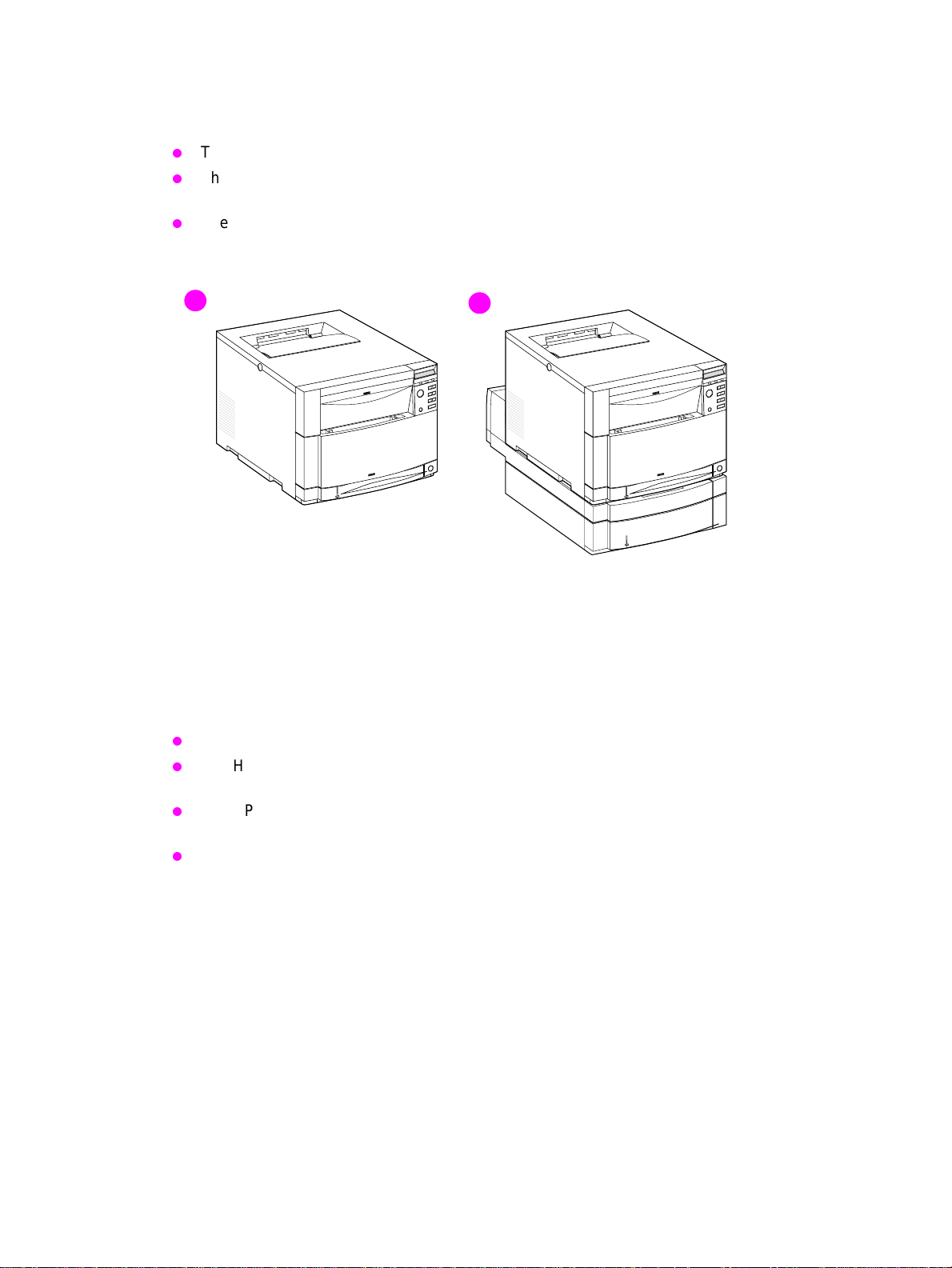
The HP LaserJet 4500 printer family pictured in Figure 1-1 has three models.
The HP LaserJet 4500 printer is the base model; it contains 32 MB of RAM.
The HP LaserJet 4500 N printer is the base model with an HP JetDirect 600N print server
(network card) and 64 MB of RAM.
The HP LaserJet 4500 DN printer is the base model with an HP JetDirect 600N print server
(network card), a 500-sheet paper feeder, a duplex unit, and 64 MB of RAM.
1
Figure 1-1 HP Color LaserJet 4500 family printers
1 HP Color LaserJet 4500 and 4500 N printers
2 HP Color LaserJet 4500 DN printer
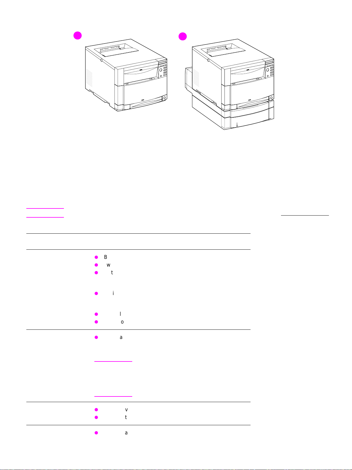
The HP LaserJet 4550 printer family pictured in Figure 1-2 has four models.
The HP LaserJet 4550 printer is the base model; it includes 64 MB of RAM.
The HP LaserJet 4550N printer is the base model with an HP JetDirect 610N print server
(network card) and 64 MB of RAM.
The HP LaserJet 4550N printer is the base model with an HP JetDirect 610N print server
(network card), a 500-sheet paper feeder, a duplex unit, and 64 MB of RAM.
The HP LaserJet 4550N printer is the base model with a 6 GB hard drive, an HP JetDirect
610N print server (network card), a 500-sheet paper feeder, a duplex unit, and 64 MB of RAM.
2
14 Printer description C7085-90921
Page 17
1
Figure 1-2 HP Color LaserJet 4550 series printers
1 HP Color LaserJet 4550 and 4550N printers
2 HP Color LaserJet 4550DN and 4550HDN printers
This printer series combines the quality and reliability of Hewlett-Packard printers with the features
listed in Table 1-1.
2
WWW For more information about printer features, ref er to the Hewlett-Pac kard website at http://www.hp .com.
Table 1-1 Printer features
Feature Description
Connectivity
Duplex
Bidirectional parallel port (requires a “C” connector)
Two enhanced input/output (EIO) slots
Optional HP JetDirect 600N print server (network card)
(included with the HP Color LaserJet 4500 N and 4500 DN
printers)
Optional HP JetDirect 610N print server (network card)
(included with the HP Color LaserJet 4550N, 4550DN and
4550HDN printers)
HP Color LaserJet 4550 series: Infrared receiver port
HP Color LaserJet 4550 series: Embedded Web server
Optional duplex unit; mounts directly beneath the printer for
two-sided printing (duplex unit is standard with the HP Color
LaserJet 4500DN, 4550DN and 4550HDN)
Note Requires 40 MB of memory; 64 MB of memory
is recommended for optimal duplex printing.
If the 500-sheet paper feeder (T ra y 3) is installed,
the duplex unit must be positioned between the
printer and Tray 3.
Environmental
Fonts
C7085-90921 Chapter 1 Printer description 15
PowerSave setting
High content of recyclable components and materials
80 internal fonts
Page 18

Table 1-1 Printer features (continued)
Feature Description
CPU
Memory—standard HP Color LaserJet 4500 series:
The Color LaserJet 4500 series formatter PCB incorportates
a 133 MHz RISC processor
The Color LaserJet 4550 series formatter PCB incorporates a
233 MHz RISC processor
32 MB RAM (Base)
64 MB RAM (HP Color LaserJet 4500 N/4500 DN)
Memory Enhancement T echnology (MEt), which automatically
compresses data to use RAM more efficiently
HP Color LaserJet 4550 series:
64 MB RAM (Base)
128 MB RAM (HP Color LaserJet 4550DN and HDN)
Memory Enhancement T echnology (MEt), which automatically
compresses data to use RAM more efficiently
Memory—optional
HP Color LaserJet 4500 series: Install 4, 8, 16, 32, or 64 MB
DIMMs into the three DIMM slots to a possible total 208 MB.
Synchronous SDRAM modules do not need to be configured
in pairs (in corresponding left and right slots). If you install
more than 208 MB of RAM, it will not be used by the printer.
HP Color LaserJet 4550 series: Install 64 or 128 MB DIMMS
into the two DIMM slots to a possible total of 192 MB. If you
install more than 192 MB of RAM, it will not be used by the
printer.
HP Color LaserJet 4550 series: 5 GB hard disk drive
(Included wit the HP Color LaserJet 4550HDN printer).
CAUTION: The HP Color LaserJet 4500 series uses 100-pin,
non-parity, SDRAM DIMMs. The HP Color LaserJet 4550
series uses 168-pin, non-parity, synchronous DRAM DIMMs.
Extended Data Output (EDO) DIMMs are not supported.
16 Printer description C7085-90921
Page 19

Table 1-1 Printer features (continued)
Feature Description
Paper handling—input
tray capacity
The capacities will vary depending on the media being used (for
example, transparencies, labels, heavy media, and envelopes).
Quantities based on 75 g/m
2
(20 lb) media for both the HP Color
LaserJet 4500 and 4550 printers:
Tray 1: 150-sheet multipurpose tray
Tray 2: 250-sheet standard cassette
Tray 3: Optional 500-sheet paper feeder (included with the HP
Color LaserJet 4500DN, 4550DN and HDN models)
Paper handling—output
(face-down, correct-order
output)
Top output bin holds up to 250 sheets of standard paper.
Rear output bin holds up to 100 sheets of standard paper.
(The output of the rear output bin is in reverse order, facing
up.)
Printer-language support HP Color LaserJet 4500 series:
HP PCL5c
PostScript™ Emulation
Automatic language switching
HP Color LaserJet 4550 series:
HP PCL 5c
HP PCL 6
PostScript™ 3 Emulation
Automatic language switching
Paper sizes supported
Print speed—
monochrome printing
Print speed—
color printing
A4/Letter
Legal
Executive
JIS B5
A5
Custom (B5 ISO)
16 pages per minute (ppm)
8 ppm for transparencies, heavy paper, and glossy paper
4 ppm
2 ppm for transparencies, heavy paper, and glossy paper
Standard interfaces The printer comes equipped with two EIO slots.
Note If the printer is not configured with a network
interface card, connect the printer using a
bidirectional parallel cable (IEEE-1284
compliant) with a “C” connector.
C7085-90921 Chapter 1 Printer description 17
Page 20
Identification
r
Model and serial numbers
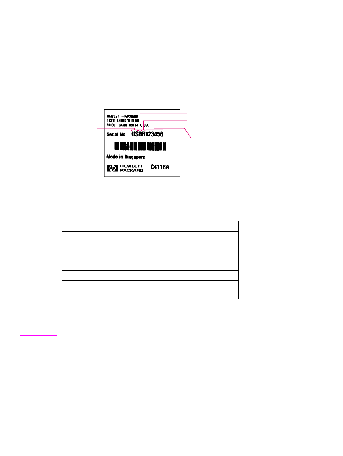
The model number and serial numbers are listed on identification labels located on the rear of the
printer. The model number is alphanumeric, such as C4084A for the HP Color LaserJet 4500. The
serial number contains information about the country of origin, the printer version, production code,
and the production number of the printer (see Figure 1-3). For information on determining the
version of printer you are servicing, see page 140.
country
of origin
Figure 1-3 Model and Serial number information
printer version
production code
production numbe
Table 1-2 Model names and numbers
Model Name Model Number
HP Color LaserJet 4500 C4084A
HP Color LaserJet 4500 N C4089A
HP Color LaserJet 4500 DN C4094A
HP Color LaserJet 4550 C7085A
HP Color LaserJet 4550N C7086A
HP Color LaserJet 4550DN C7087A
HP Color LaserJet 4550HDN C7088A
Note T wo v ersions of the HP Color LaserJet 4500 series printers are available. Bef ore servicing the printer
or ordering parts, you will need to identify which printer version you are servicing. For more
information, see page 140. The HP Color LaserJet 4550 series printer, unless otherwise specified,
is equivalent to the later version of the HP Color LaserJet 4500 series printer.
18 Printer description C7085-90921
Page 21
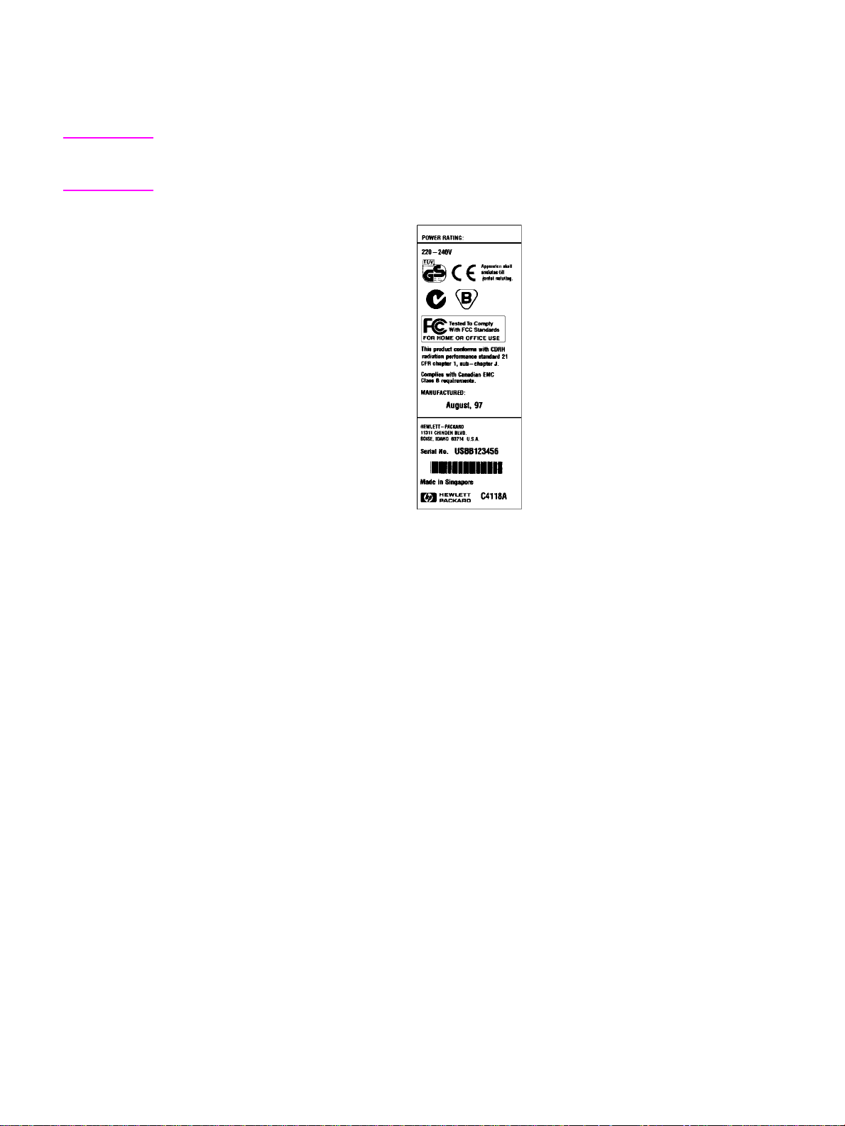
Power and regulatory information
The identification labels on the rear of the printer also contain power rating and regulatory
information as shown in Figure 1-4.
CAUTION Converting the voltage on the printer can damage the printer. Do not use any voltage other than the
operating voltage. An y attempt to convert operating voltages will void the product warranty (f or example,
attempting to change a 110V printer to a 220V printer).
Figure 1-4 Sample label
C7085-90921 Chapter 1 Printer description 19
Page 22

Site requirements
The printer must be kept in a proper location to maintain the performance lev el that has been set at
the factory. In particular, be sure that the environment adheres to the specifications listed in this
chapter.
Below are recommendations for the printer location and placement.
Make sure the printer has the following:
a well-ventilated, dust-free area
a hard, level surface (not more than a 2° angle):
• for the HP Color LaserJet 4500 and 4500N, the surface must support 51 kg (112 lb)
• for the HP Color LaserJet 4500DN, the surface must support 77 kg (169 lb)
• for the HP Color LaserJet 4550 and 4550N, the surface must support 51 kg (112 lb)
• for the HP Color LaserJet 4550DN and 4550HDN, the surface must support 77 kg (169 lb)
a level surface that supports all four corners of the 500-sheet paper feeder
a constant temperature and humidity (Do not install near water sources, humidifiers, air
conditioners, refrigerators, or other major appliances)
Make sure to keep the printer:
away from direct sunlight, dust, open flames, or ammonia fumes.
away from the direct flow of exhaust from air ventilation systems.
away from walls or other objects. There must be enough space around the printer for proper
access and ventilation. See Figure 1-5 on page 21.
20 Printer description C7085-90921
Page 23
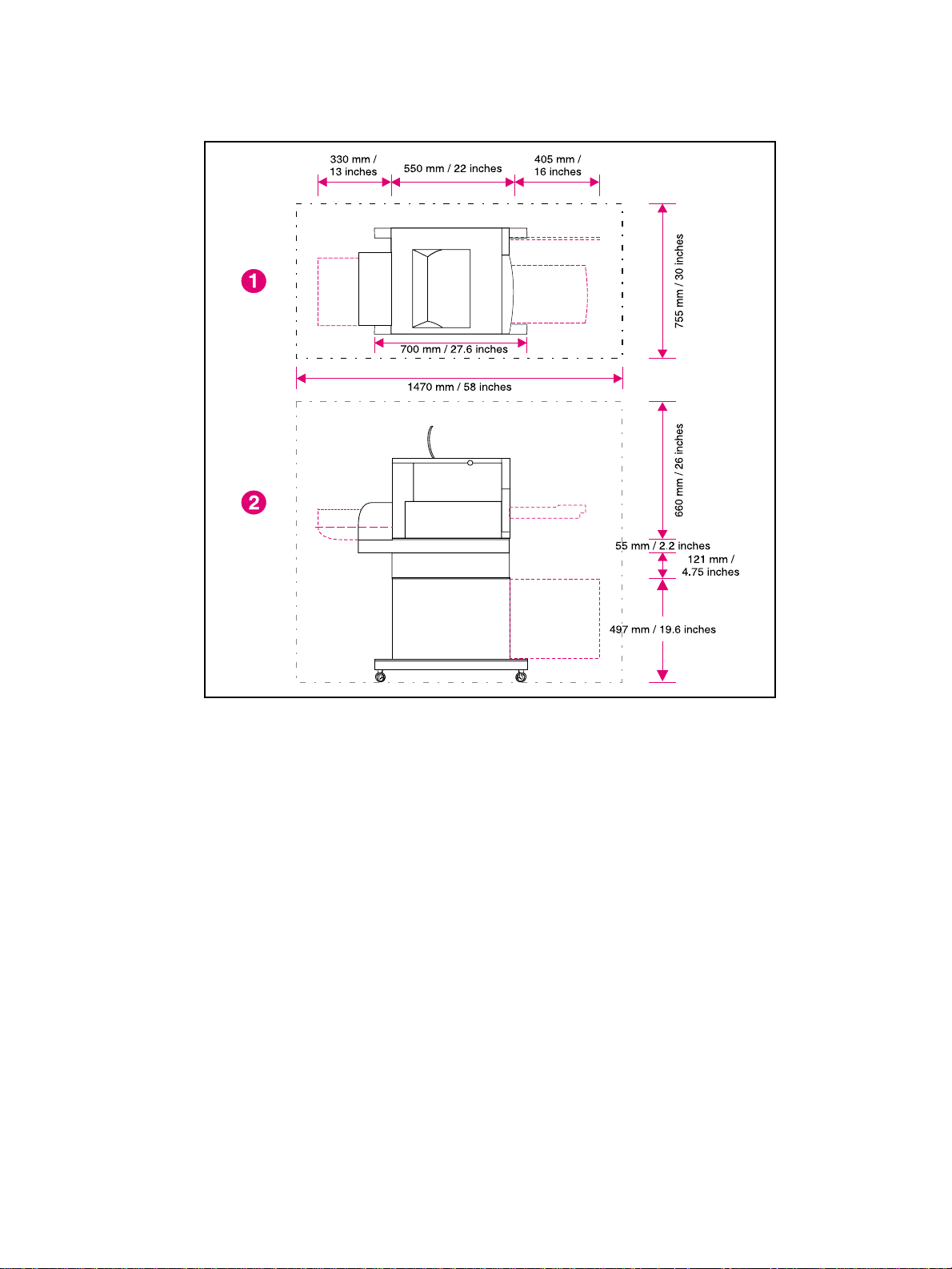
Space requirements
The printer must have the following amounts of space above and around it.
Figure 1-5 Space requirements
1 Top view
2 Side view
C7085-90921 Chapter 1 Printer description 21
Page 24
Electrical specifications
Table 1-3 lists the electrical specifications required to run the printer safely.
Table 1-3 Electrical specifications
Item 110-volt models 220-volt models
Power requirements 100-127 V (+/- 10%)
50/60 Hz (+/- 2 Hz)
Power consumption
(typical)
During printing
During standby
During PowerSave
Off
Minimum recommended
circuit capacity for typical
product
*
When the printer is in standby (off) mode, it continues to consume a minimal amount of energy.
*
470 W (average)
80 W (average)
4500: 32 W
4550: 0 W
4500: 16.0 A at 120 V
4550: 10.2 A at 120 V
220-240 V (+/- 10%)
50/60 Hz (+/- 2 Hz)
480 W (average)
90 W (average)
4500: 32W
4550: 0 W
4500: 7.1 A at 220 V
4550: 5.1 A at 220 V
Note This information is preliminary and might not be current. Please see http://www.hp.com/support/
lj4550 for current information.
Environmental specifications
Keep the printer within the environmental conditions shown in Table 1-4 for optimum performance.
Table 1-4 Environmental specifications
Item Operating
Temperature
Recommended
Allowed
Humidity
Recommended
Allowed
Altitude
Allowed 0 to 3100 m
20° to 26° C (68° to 79° F)
15° to 30° C (59° to 86° F)
20% to 50% RH
10% to 80% RH
(0 to 10,000 ft)
22 Printer description C7085-90921
Page 25
Consumable storage requirements
The life of consumables is greatly affected by their storage environment. Use Table 1-5 to determine
the shelf life of stored consumables.
Table 1-5 Consumable storage requirements
Item Storage time Storage condition
Temperature Normal (maximum of
Maximum temperature
change rate
Humidity Normal (maximum of
Atmospheric pressure 460 to 760 mm Hg (18.1 to 29.9 in Hg)
Average storage time 1 year
Printer specifications
Table 1-6 describes the dimensions of the printer.
Table 1-6 Printer dimensions
HP Color LaserJet
4500, 4500N
0° to 35° C (32° to 95°
2.5 years)
Severe (maximum of
18 days)
40° to 15° C (104° to 59° F) within 3 minutes
-20° to 25° C (-4° to 77° F) within 3 minutes
2.5 years)
Severe (maximum of
18 days)
HP Color LaserJet
4500 DN
F)
High 35° to 40° C (95°
to 104° F)
Low 0° to -20° C (32°
to -4° F)
35% to 85% RH
High 85% to 95% RH
Low 10% to 35% RH
HP Color LaserJet
4550, 4500N
HP Color LaserJet
4550DN, 4550HDN
Height 395 mm (15.6 inches) 578 mm (22.8 inches) 395 mm (15.6 inches) 578 mm (22.8 inches)
Width 500 mm (19.7 inches) 500 mm (19.7 inches) 500 mm (19.7 inches) 500 mm (19.7 inches)
Depth 559 mm (22 inches) 709 mm (27.9 inches) 559 mm (22 inches) 709 mm (27.9 inches)
Weight 57 kg (125 lb) 75 kg (165 lb) 57 kg (125 lb) 75 kg (165 lb)
Table 1-7 lists the acoustic emissions of the printer when it is printing and when it is in standby mode.
Table 1-7 Acoustic emissions
HP Color LaserJet 4500 Series HP Color LaserJet 4550 Series
Operating position
Printing
Standby
Bystander 1m
Printing
Standby
Sound power
Printing
Standby
Per ISO 9296, DIN 45635, T.19
L
58 dB(A)
PA
L
49 dB(A)
PA
Per ISO 7779, DIN 45635, T.19
L
52 dB(A)
PA
L
45 dB(A)
PA
Per ISO 9296
L
= 6.6 bels(A)
WAd
L
= 5.8 bels(A)
WAd
Per ISO 9296, DIN 45635, T.19
L
56 dB(A)
PA
L
48 dB(A)
PA
Per ISO 7779, DIN 45635, T.19
L
52 dB(A)
PA
L
44 dB(A)
PA
Per ISO 9296
L
= 6.7 bels(A)
WAd
L
= 5.3 bels(A)
WAd
C7085-90921 Chapter 1 Printer description 23
Page 26

Note This product emits a sound intensity level, L
in close proximity to users.
Maximum duty cycle is 35,000 pages per month.
, at 6.4 bel during printing. Do not place the printer
WAd
24 Printer description C7085-90921
Page 27
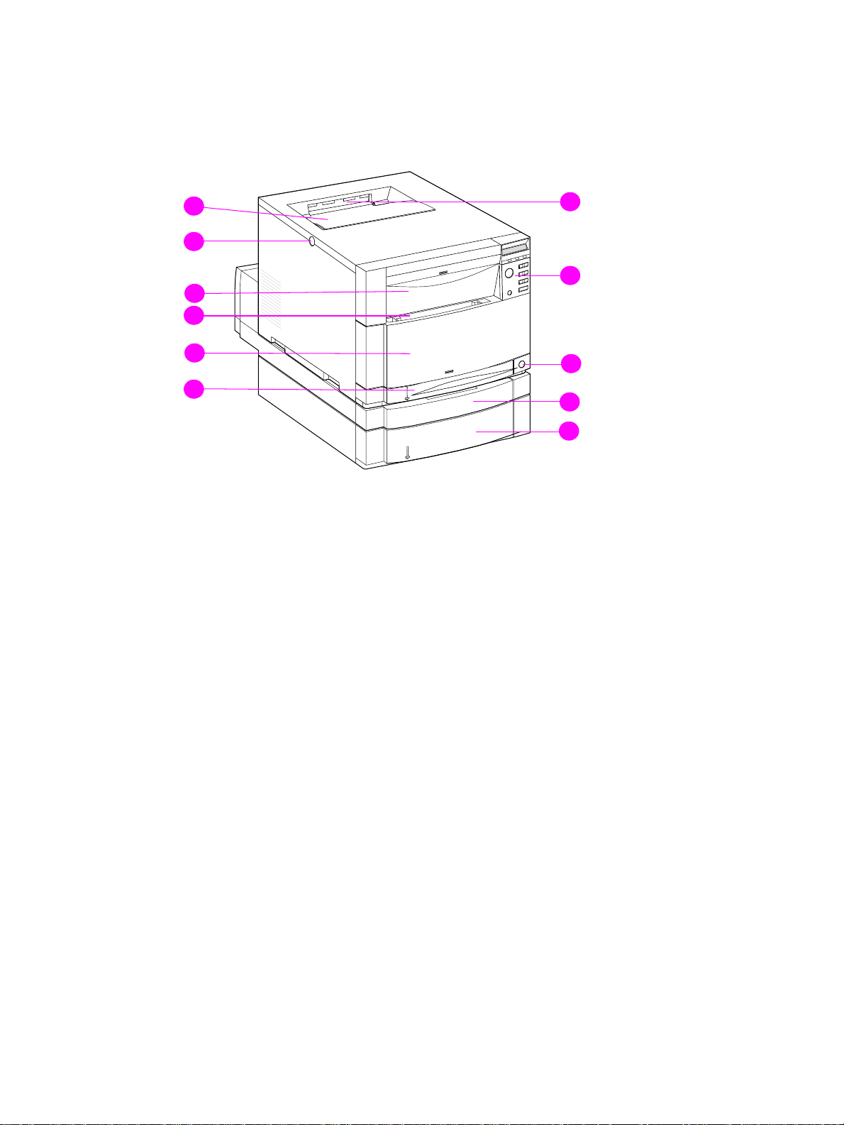
Printer assemblies
Figures 1-6 and 1-7 show the location of each major assembly in the printer. These assemblies are
described in Chapter 3.
11
10
9
8
7
6
Figure 1-6 Front view, HP Color LaserJet 4500 and HP Color LaserJet 4550
(shown with 500-sheet paper feeder and duplex unit)
1 Top output bin
2 Printer control panel
3 Power switch (standby button)
1
2
3
4
5
4 Duplex unit drawer (optional on 4500, 4500N, 4550 and 4550N models)
5 Tray 3 (500-sheet tray; optional on 4500, 4500N, 4550 and 4550N models)
6 Tray 2 (250-sheets standard tray)
7 Intermediate Transfer Belt (ITB) drawer (transfer belt access)
8 Tray 1 (150-sheet multipurpose tray)
9 Drum drawer (imaging drum access)
10 Top cover release (toner access) button
11 Toner cartridge access cover
C7085-90921 Chapter 1 Printer description 25
Page 28
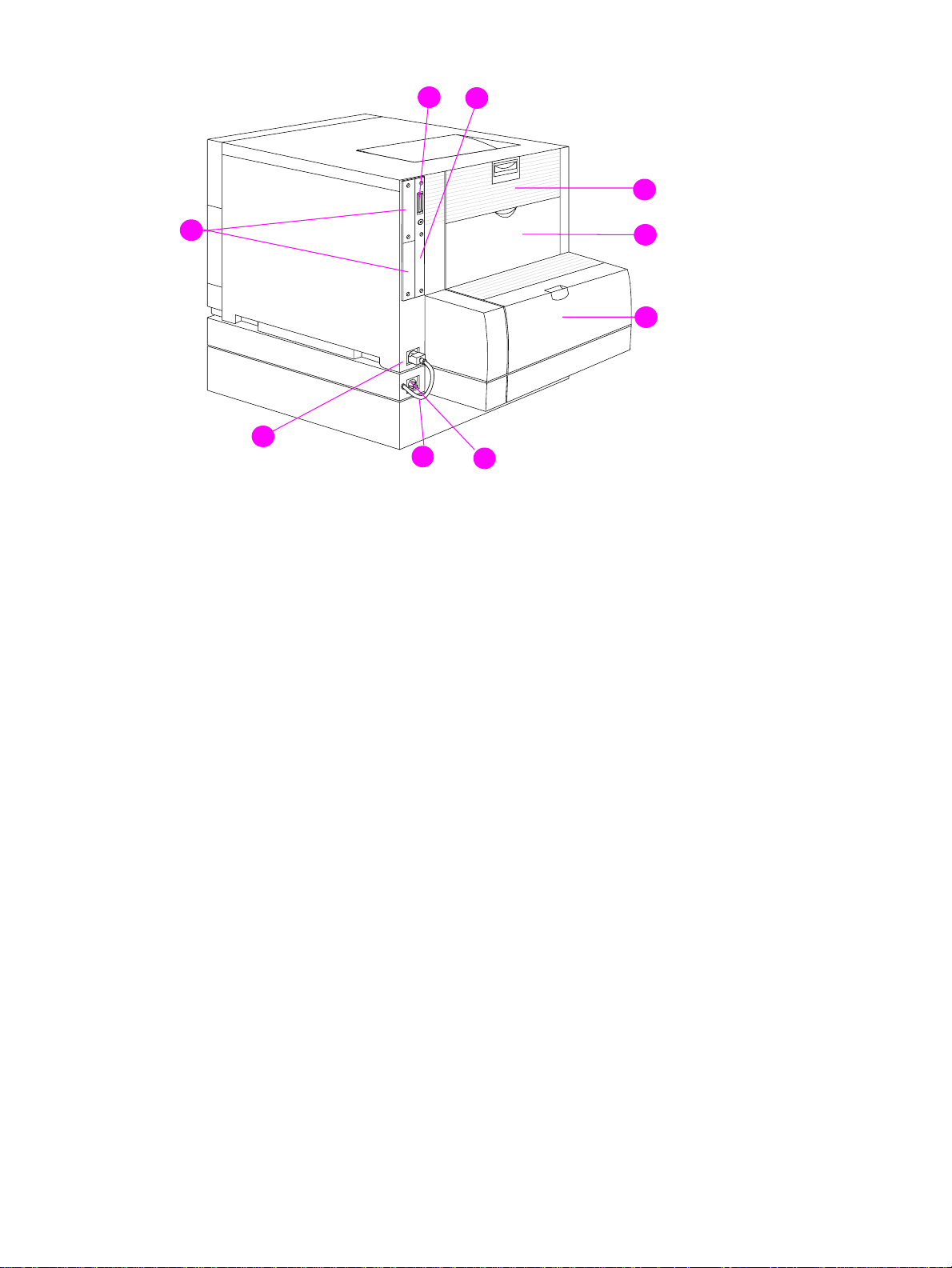
8
9
1
7
6
5
4
2
3
Figure 1-7 Rear view, HP Color LaserJet 4500 (shown with 500-sheet paper feeder and duplex unit)
1 Rear door (fuser access)
2 Rear output bin door
3 Cover for duplex unit
4 Power receptacle for duplex unit
5 Duplex unit power cord to the printer
6 Printer power receptacle
7 EIO slots
8 Parallel connector (“C” connector)
9 Memory access
26 Printer description C7085-90921
Page 29
9
8
1
7
6
5
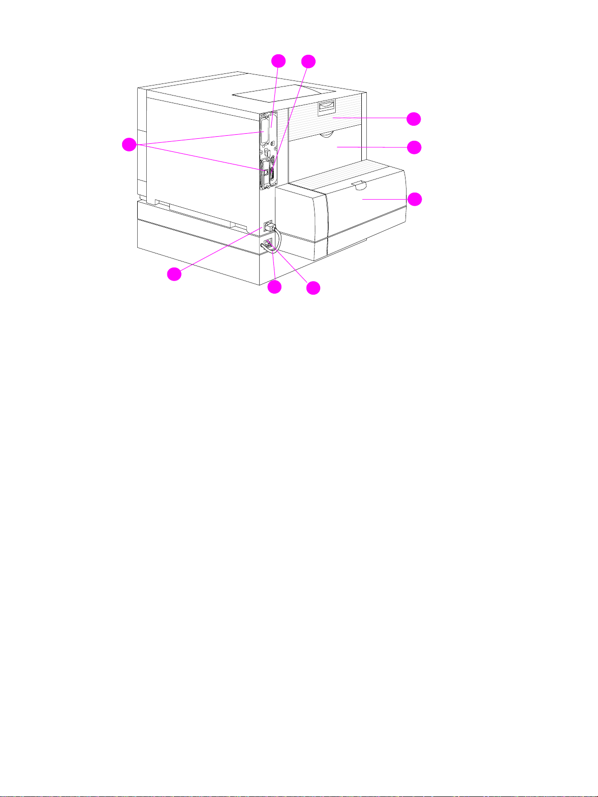
Figure 1-8 Rear view, HP Color LaserJet 4550
1 Rear door (fuser access)
2 Rear output bin door
3 Cover for duplex unit
4 Power receptacle for duplex unit
5 Duplex unit power cord to the printer
2
3
4
(shown with 500-sheet paper feeder and duplex unit)
6 Printer power receptacle
7 EIO slots
8 Parallel connector (“C” connector)
9 Memory access
C7085-90921 Chapter 1 Printer description 27
Page 30

Media requirements
Selecting print media
You can use many types of paper and other print media with this printer. This section provides
guidelines and specifications for selecting and using different print media.
Before purchasing any media or specialized forms in quantity, verify that your paper supplier
obtains and understands the print media requirements specified in the HP LaserJet Family Print
Media Guide. The guide is available through HP Direct. See the online user guide for ordering
information.
It is possible that media could meet all of the guidelines in this chapter and still not print
satisfactorily. This may be a result of abnormal characteristics of the printing environment or to
other variables over which Hewlett-Packard has no control (for example, extremes in temperature
and humidity).
Hewlett-Packard recommends testing any media before buying it in large quantities.
CAUTION Using media that does not conform to the specifications listed here and in the HP LaserJet Family
Print Media Guide can cause problems that require service. This service is not covered by the
Hewlett-Packard warranty or service agreements.
Media specifications
For optimum results, use con v entional 75 g/m2 (20 lb) xerographic paper. Verify that the paper is of
good quality and is free of cuts, nicks, tears, spots, loose particles, dust, wrinkles, curls, or bent
edges. Avoid fanning the print media before loading it into the paper trays.
28 Printer description C7085-90921
Page 31

Supported media weights and sizes
Table 1-8 shows the media types and sizes supported by the printer and the printer accessories.
Table 1-8 Supported media specifications
Tray Supported media Media
specifications
Tray 1 Paper
A4/Letter
Legal
Executive
JIS B5
A5
Custom
Minimum size:
76 by 127 mm (3 by 5 in)
Maximum size:
216 by 356 mm (8.5 by 14 in)
Transparencies
A4/Letter
Glossy Paper
Envelopes
(Tray 1 only)
Com10
Monarch
C5
DL
B5 (JIS)
Single-sided:
If less than or equal
to 148 mm width:
60 to 176 g/m
(16 to 47 lb)
If more than or equal
to 148 mm width:
60 to 135 g/m
(16 to 36 lb bond)
Two-sided:
64 to 105
(17 to 28 lb bond)
0.13 mm (5 mil)
120 g/m
(32 lb/80 lb text)
Maximum weight:
90 g/m
bond)
2
2
(24 lb
g/m
Capacity
150 sheets of 75 g/m
(20 lb) paper
2
Do not load more than the
maximum stack height of
15 mm (0.6 in)
2
2
Limit of 50
Limit of 50 sheets
Limit of 10
2
Labels
(Tray 1 only)
Cardstock (postcards)
(Tray 1 only)
Tray 2* Paper
A4/Letter
Legal
Executive
JIS B5
A5
Custom (B5 ISO)**
Transparencies
Glossy Paper
Maximum weight:
176 g/m
2
(47 lb
bond)
Maximum size:
200 mm by 148
mm
(7.87 in by 5.82 in)
Single Sided
60 to 105 g/m
(16 to 28 lb bond)
Two Sided:
64-105 g/m
2
(17-
28 lb. bond)
0.13 mm (5 mil)
120 g/m
2
(32 lb/80 lb text)
Limit of 50
Do not load more than the
maximum stack height of
15 mm (0.6 in)
250 sheets of 75 g/m
2
(20 lb) paper
Limit of 50 transparencies
Limit of 200 sheets glossy
2
C7085-90921 Chapter 1 Printer description 29
Page 32

Table 1-8 Supported media specifications (continued)
Tray Supported media Media
Capacity
specifications
Tray 3*
(optional)
Duplex
printing
accessory
(optional)
*Trays 2 and 3 do not support the range of custom sizes available in Tray 1.
**Trays 2 and 3 use custom size, specifically for B5 ISO.
Paper
A4/Letter
Legal
Executive
JIS B5
Custom (B5 ISO)**
Transparencies
Glossy Paper
Paper
A4/Letter
Legal
Executive
JIS B5
Single Sided
60 to 105 g/m
(16 to 28 lb bond)
Two Sided:
64-105 g/m
28 lb. bond)
0.13 mm (5 mil)
120 g/m
(32 lb/80 lb text)
64 to 105 g/m
(17 to 28 lb bond)
2
(17-
2
2
500 sheets of 75 g/m2
2
(20 lb) paper
Limit of 50 transparencies
Limit of 500 sheets glossy
Note Use only HP-supported transparencies (HP part number C2934A, Letter size; C2936A, A4 size).
Non-supported media
Use the following guidelines to avoid poor print quality or damage to your printer:
Do not use paper that is too rough.
Do not use paper that is embossed or coated unless it is specifically recommended for use in
this printer.
Do not use paper with cutouts or perforations other than standard three-hole punched paper.
Do not use multipart forms.
Do not use paper with irregularities such as tabs or staples.
Do not use letterhead paper with low temperature dyes or thermography. Preprinted forms or
letterhead must use inks that can tolerate temperatures of 190° C (374° F) for 0.1 second.
Do not use any media that produces hazardous emissions, or that melts, offsets, or discolors
when exposed to 190° C (374° F) for 0.1 second.
Do not use paper that has already been printed on or fed through a photocopier or printer.
Do not use paper with a watermark if you are printing solid patterns.
Do not duplex on glossy paper. Doing so will result in jams and print-quality problems.
Do not use transparencies that are not specified for use with HP Color LaserJet printers.
30 Printer description C7085-90921
Page 33

Printing on special media
Use these guidelines when printing on special types of media.
For optimum results, use conventional 75 g/m2 (20 lb) xerographic paper.
Verify that the paper is of good quality and free of cuts, nicks, tears, spots, loose particles, dust,
wrinkles, curls, or bent edges.
Transparencies
When printing on transparencies, use the following guidelines.
Do not send transparencies from Tray 2 to the rear output bin. The toner will be warm and may
cause the transparencies to stick together.
Send transparencies to the top output bin.
Handle transparencies using the edges. Oils from your fingers can remain on the transparency
and can cause print quality problems.
Use only overhead transparencies recommended for use in this printer. Table 1-9 describes the
recommended specifications for transparencies.
CAUTION Do not use DeskJet (inkjet) transparencies in this printer. The transparencies can become o verheated
and melt, causing serious damage to your printer. Hewlett-Packard recommends using HP Color
LaserJet Transparencies with this printer. HP products are designed to work together for optimum
printing results.
Table 1-9 Printing on transparencies
Description Specifications
Electrical surface
resistivity
Fusing compatibility Materials must not discolor, melt, offset, or release
Caliper (thickness) 0.12 mm (0.0048 in) to 0.13 mm (0.0052 in)
2.0 to 15 by 10 ohms per square inch
hazardous emissions when heated to 190° C
(374° F) for 0.1 second.
Glossy paper
For optimum results when printing on glossy paper , select the glossy print setting in the printer driver.
You can also use the printer control panel to set the media type to
GLOSS for the input tray you are
using. Because this setting affects all print jobs, it is important to return the printer to its original
settings once your job has printed. See the section in the online user guide on configuring input trays.
Note Do not duplex on glossy paper. Doing so will result in jams and print quality problems.
Colored paper
Colored paper should be of the same high quality as white xerographic paper. Pigments used must
be able to withstand the printer’s fusing temperature of 190° C (374° F) for 0.1 second without
deterioration. Do not use paper with a colored coating that was added after the paper was produced.
The printer creates colors by printing patterns of dots, overlaying and varying their spacing to
produce various colors. V arying the shade or color of your paper will aff ect the shades of y our printed
colors.
C7085-90921 Chapter 1 Printer description 31
Page 34

Heavy paper
Use Tray 1 for paper that is 105-157 g/m2 (28-42 lb bond). For optimum results when printing on
heavy paper , select the hea vy print setting in the printer driver. You can also use the printer control
panel to set the media type to
HEAVY for the input tra y you are using. Because this setting aff ects all
print jobs, it is important to return the printer to its original settings once your job has printed.
CAUTION Do not use paper that is heavier than the recommended specification for this printer. Doing so can
cause misfeeds, jams, inferior print quality, and excessive mechanical wear. See Table 1-8 for
supported paper types and sizes.
Envelopes
Envelopes can only be printed from Tray 1. For information about loading envelopes, see the
section in the online user guide about loading envelopes into Tray 1.
Adhering to the following guidelines will help ensure proper printing of envelopes and help prevent
printer jams:
Do not load more than 10 envelopes into Tray 1.
The weight rating of envelopes should not exceed 90 g/m2 (24 lb).
Envelopes should be flat.
Envelopes must not be wrinkled, nicked, or otherwise damaged.
Envelopes with peel-off adhesive strips must use adhesives that can withstand the heat and
pressures of the printer’s fusing process.
Envelopes should be loaded with the flaps f acing a w a y f rom the printer and tow ard the left side
of the printer.
CAUTION To prevent severe printer damage, do not use envelopes that have windows, clasps, snaps, or
synthetic materials.
Labels
Note To print labels, Hewlett-Packard recommends configuring Tra y 1 as a cassette and setting the tra y’s
media type to LABELS in the printer control panel.
When printing labels, use the following guidelines:
Verify that the label’s adhesive material can tolerate temperatures of 190° C (374° F) for 0.1
second.
Verify that adhesive material is not exposed between the labels. Exposed areas can cause
labels to peel off during printing, which can cause printer jams. Exposed adhesive can also
cause damage to printer components.
Do not re-feed a sheet of labels.
Verify that labels lie flat.
Do not use labels that are wrinkled, bubbled, or otherwise damaged.
32 Printer description C7085-90921
Page 35

Preprinted forms and letterhead
Observe the following guidelines for best results with preprinted forms and letterhead.
Forms and letterhead must be printed with heat-resistant inks that will not melt, vaporize, or
release hazardous emissions when subjected to the printer’s fusing temperature of
approximately 190° C (374° F) for 0.1 second.
Inks must be non-flammable and should not adversely affect any printer rollers.
Forms and letterhead should be sealed in a moisture-proof wrapping to prev ent changes during
storage.
Before you load preprinted paper such as forms and letterhead, verify that the ink on the paper is
dry. During the fusing process, wet ink can come off of preprinted paper.
Recycled paper
This printer supports the use of recycled paper. Recycled paper must meet the same specifications
as standard paper; refer to the HP LaserJet Family Print Media Guide, available through HP Direct.
See the online user guide for ordering information. Hewlett-P ackard recommends that recycled paper
contain no more than 5 percent groundwood.
C7085-90921 Chapter 1 Printer description 33
Page 36

Environmental Product Stewardship Program
Protecting the environment
Hewlett-Packard Company is committed to providing quality products in an environmentally sound
manner. This HP LaserJet printer has been designed with sev eral attrib utes to minimize impacts on
our environment.
This HP LaserJet printer design eliminates:
Ozone Emissions—This product has been designed to minimize ozone emissions and avoid
the need for an ozone filter.
CFC Usage—Class I U.S. Clean Air Act stratospheric ozone-depleting chemicals
(chlorofluorocarbons [CFCs], for example) have been eliminated from the manufacturing sites
that produce this printer. This practice coincides with the 1987 “Montreal Protocol on
Substances that Deplete the Ozone Layer” and its subsequent amendments. CFCs are not
used in manufacturing of the packing.
This HP LaserJet printer design reduces:
Energy Consumption—Energy usage drops significantly from printing mode to PowerSave
mode.
As an ENERGY STAR partner, HewlettPackard Company has determined
that this product meets E
Guidelines for energy efficiency.
NERGY STAR
Paper Use—The printer’s optional duplex printing accessory provides two-sided printing,
reducing paper usage and the resulting demands on natural resources.
The design of this HP LaserJet printer facilitates the recycling of:
Plastics—Major plastic parts have markings that enhance the ability to identify plastics for
recycling purposes at the end of the printer’s life.
HP Toner Cartridges/Photoconductive Drum—In many countries, this product’s toner
cartridge/drum can be returned to HP at the end of its useful life. A prepaid shipping label and
instructions on how to return the toner cartridge/drum are included with the replacement toner
cartridge/drum. If your country is not listed in the replacement’s brochure, call your local HP
Sales and Service Office for further instructions.
HP recycling program information:
This HP LaserJet printer also contributes to protecting the environment in the following ways:
HP LaserJet printing supplies—In many countries, this product's printing supplies (e.g.,
toner cartridge, drum, fuser) can be returned to HP through the HP Planet Partners Printing
Supplies Environmental Program. An easy-to-use take-back component of the program is
available in over 25 countries.
Multilingual program information and instructions are included in ev ery new HP LaserJet Toner
Cartridge and Consumables box.
HP Planet Partners printing supplies environmental program—Since 1990, the HP
LaserJet Toner Cartridge Recycling Program has collected more than 39 million used LaserJet
toner cartridges that otherwise might have been discarded in the world’s landfills. The HP
34 Printer description C7085-90921
Page 37

LaserJet toner cartridges go to a collection center and are bulk-shipped to our recycling partners
who disassemble the cartridge parts for recycling. Materials are separated and converted into
raw materials for use by other industries to make a variety of useful products.
U.S. Recycling Returns—For a more environmentally responsible return of used cartridges and
consumables, HP encourages the use of bulk returns. Simply bundle two or more cartridges
together and use a single, prepaid, and pre-addressed UPS label that is supplied in the package.
WWW For more information, call (800) 340-2445 (U .S. only) or visit the HP LaserJet Supplies website at http:/
/www.hp.com/ljsupplies/planet_index.html.
Non-U.S. Recycling Returns—Non-U.S. customers should call the local HP Sales and Service
Office for further information regarding availability of the HP Planet Partners LaserJet Toner
Cartridge and Consumables Recycling Program.
Paper—This printer is suited for the use of recycled papers (according to DIN 19 309) when the
paper meets the guidelines outlined in the HP LaserJet Family Print Media Guide.
For downloadable manuals, go to http://www.hp.com/support/lj4550
. When you connect, select
Manuals. The user guide is provided on CD-ROM, which allo ws the same high-quality inf ormation to
be provided without consuming the large quantities of energy and natural resources required to
produce traditional paper manuals.
To ensure longevity of your HP LaserJet printer, HP provides the following:
Extended Warranty—HP SupportPack provides coverage for the HP hardware product and all
HP-supplied internal components. The hardware maintenance covers a three-year period from
date of the HP product purchase. HP SupportPack must be purchased by the customer within 90
days of the HP product purchase.
WWW Information on HP SupportPack is av ailable on the W eb at http://www .hp .com/ under the HP Services
and Support section. International customers can contact the nearest HP-authorized reseller about
this service.
Spare Parts and Consumables Availability—Spare parts and consumable supplies for this
product will be made available for at least five years after production has stopped.
C7085-90921 Chapter 1 Printer description 35
Page 38

Regulatory statements
HP Color LaserJet 4500
For the most current regulatory statements regarding the HP Color LaserJet 4500 series, please
see the HP Color LaserJet 4500 User Guide, or go to http://www.hp.com/cposupport/prodhome/
hpcolorlas7857.html.
HP Color LaserJet 4550
For the most current regulatory statements regarding the HP Color LaserJet 4550 series, please
see the HP Color LaserJet 4550 User Guide, or go to http://www.hp.com/support/lj4550
.
36 Printer description C7085-90921
Page 39

Safety information
Laser safety statement
The Center for Devices and Radiological Health (CDRH) of the U.S. Food and Drug Administration
has implemented regulations for laser products manufactured since 1 August 1976. Compliance is
mandatory for products marketed in the United States. The printer is certified as a “Class 1” laser
product under the U.S. Department of Health and Human Services (DHHS) Radiation Performance
Standard according to the Radiation Control for Health and Safety Act of 1968. Since radiation
emitted inside the printer is completely confined within protective housings and external covers, the
laser beam cannot escape during any phase of normal user operation.
Material Safety Data Sheet
The Toner Cartridge/Drum Material Safety Data Sheet (MSDS) can be obtained by visiting the
website at http://www .ljsupplies.com/planetpartners/datasheets.html
see support information in this guide for appropriate phone numbers and information.
Toner safety
Hewlett-Packard encourages responsible disposal of HP LaserJet printer consumable items through
its Environmental Collection Program. F or details on this program, see the recycling instruction guide
enclosed with each consumable item.
. International customers should
Note In case of toner spills, skin and clothing are best cleaned by removing as much toner as possib le with
a dry tissue, then washing with cold water. Hot water causes toner to permanently set into clothing.
C7085-90921 Chapter 1 Printer description 37
Page 40

Laser statement for Finland
LASERTURVALLISUUS
Luokan 1 laserlaite
Klass 1 Laser Apparat
HP LaserJet 4500, 4550-laserkirjoitin on käyttäjän kannalta turvallinen luokan 1 laserlaite.
Normaalissa käytössä kirjoittimen suojakotelointi estää lasersäteen pääsyn laitteen ulkopuolelle.
Laitteen turvallisuusluokka on määritetty standardin EN 60825-1 (1994) mukaisesti.
VAROITUS !
Laitteen käyttäminen muulla kuin käyttöohjeessa mainitulla tavalla saattaa altistaa käyttäjän
turvallisuusluokan 1 ylittävälle näkymättömälle lasersäteilylle.
VARNING !
Om apparaten används på annat sätt än i bruksanvisning specificerats, kan användaren utsättas
för osynlig laserstrålning, som överskrider gränsen för laserklass 1.
HUOLTO
HP LaserJet 4500, 4550-kirjoittimen sisällä ei ole käyttäjän huollettavissa olevia kohteita. Laitteen
saa avata ja huoltaa ainoastaan sen huoltamiseen koulutettu henkilö. Tällaiseksi
huoltotoimenpiteeksi ei katsota väriainekasetin vaihtamista, paperiradan puhdistusta tai muita
käyttäjän käsikirjassa lueteltuja, käyttäjän tehtäväksi tarkoitettuja ylläpitotoimia, jotka voidaan
suorittaa ilman erikoistyökaluja.
VARO !
Mikäli kirjoittimen suojakotelo avataan, olet alttiina näkymättömälle lasersäteilylle laitteen ollessa
toiminnassa. Älä katso säteeseen.
VARNING !
Om laserprinterns skyddshölje öppnas då apparaten är i funktion, utsättas användaren för osynlig
laserstrålning. Betrakta ej strålen.
Tiedot laitteessa käytettävän laserdiodin säteilyominaisuuksista:
Aallonpituus 770-795 nm
Teho 5 mW
Luokan 3B laser
38 Printer description C7085-90921
Page 41

2 Service approach
Chapter contents
Service approach . . . . . . . . . . . . . . . . . . . . . . . . . . . . . . . . . . . . . . . . . . . . . . . . . . . . . . . . . . . . .40
Parts and supplies. . . . . . . . . . . . . . . . . . . . . . . . . . . . . . . . . . . . . . . . . . . . . . . . . . . . . . . . . . . . .41
Ordering parts. . . . . . . . . . . . . . . . . . . . . . . . . . . . . . . . . . . . . . . . . . . . . . . . . . . . . . . . . . . . .41
Ordering consumables . . . . . . . . . . . . . . . . . . . . . . . . . . . . . . . . . . . . . . . . . . . . . . . . . . . . . .41
Exchange program . . . . . . . . . . . . . . . . . . . . . . . . . . . . . . . . . . . . . . . . . . . . . . . . . . . . . . . . .42
Consumables . . . . . . . . . . . . . . . . . . . . . . . . . . . . . . . . . . . . . . . . . . . . . . . . . . . . . . . . . . . . .42
World Wide Web. . . . . . . . . . . . . . . . . . . . . . . . . . . . . . . . . . . . . . . . . . . . . . . . . . . . . . . . . . .42
HP Service Parts Information Compact Disc . . . . . . . . . . . . . . . . . . . . . . . . . . . . . . . . . . . . .42
HP Support Assistant Compact Disc . . . . . . . . . . . . . . . . . . . . . . . . . . . . . . . . . . . . . . . . . . .42
Ordering related documentation and software . . . . . . . . . . . . . . . . . . . . . . . . . . . . . . . . . . . . 43
Warranty statement. . . . . . . . . . . . . . . . . . . . . . . . . . . . . . . . . . . . . . . . . . . . . . . . . . . . . . . . . . . .44
Hewlett-Packard warranty statement . . . . . . . . . . . . . . . . . . . . . . . . . . . . . . . . . . . . . . . . . . .44
Onsite service agreements. . . . . . . . . . . . . . . . . . . . . . . . . . . . . . . . . . . . . . . . . . . . . . . . . . .45
C7085-90921 Chapter 2 Service approach 39
Page 42

Service approach
Printer repair normally begins by using the printer’s internal diagnostics and the three-step process
below.
Step 1 Isolate the problem to the major system (for example, the host computer, the network
Step 2 Determine if the problem is located in the accessories or in the printer engine.
Step 3 Troubleshoot the problem using the procedures in Chapter 7.
Once a faulty part is located, the printer can usually be repaired at the assembly level by replacing
field replaceable units (FRUs). Some mechanical assemblies might need to be repaired at the
subassembly level. Hewlett-Packard does not support replacement of components on the printer
circuit assembles.
or server, or the printer system).
40 Service approach C7085-90921
Page 43

Parts and supplies
Ordering parts
Field replaceable and accessory part numbers are found in Chapter 8 of this manual. Replacement
parts can be ordered from HP’s Commercial Support Services Organization-Americas (CSSO-A) or
HP’s Commercial Support Services Organization-Europe (CSSO-E).
Note Use only accessories specifically designed for this printer. Accessories can be ordered from an
authorized service or support provider. See “Ordering related documentation and software” on page
43 and “Ordering parts” on page 325 for additional ordering information.
By phone:
Commercial Support Services Organization-Americas (CSSO-A)
(1)(800) 227-8164 (U.S. only)
Commercial Support Services Organization-Europe (CSSO-E)
(49) (070) 3114-2253
By mail:
Hewlett-Packard Company
CSSO-A
8050 Foothills Blvd.
Roseville, CA 95678
Hewlett-Packard Company
CSSO-E
Wolf-Hirth Straße 33
D-7030 Böblingen, Germany
Ordering consumables
Consumables can be ordered directly from Hewlett-Packard. The phone numbers for ordering
consumables are:
U.S. (800) 538-8787
Canada (800) 387-3154; Toronto (416) 671-8383
United Kingdom 0734-441212
Other local phone numbers may also be available
C7085-90921 Chapter 2 Service approach 41
Page 44

Exchange program
HP offers remanuf actured assemblies for some parts. These are identified in Chapter 8 and can be
ordered through Commercial Support Services Organization-Americas (CSSO-A) or Commercial
Support Services Organization-Europe (CSSO-E).
Consumables
Paper and toner cartridges can be ordered directly from Hewlett-Packard. See Chapter 8 for
ordering information.
World Wide Web
Printer drivers, updated HP printer software, and product and support information can be obtained
from the following URL:
in the U.S.http://www.hp.com/go/support
Printer drivers may be obtained from the f ollowing sites:
In China:ftp://www.hp.com.cn/go/support
In Japan:ftp://www.jpn.hp.com/go/support
In Korea:http://www.hp.co.kr/go/support
In Taiwan:http://www.hp.com.tw/go/support
or the local driver website http://www.dds.com.tw
HP Service Parts Information Compact Disc
This powerful, CD-ROM-based parts information tool is designed to give users fast, easy access to
parts information such as pricing and recommended stocking lists for a wide range of HP products.
To subscribe to this quarterly service in the U.S. or Canada, call (800) 336-5987. In Asia Pacific,
call (65) 740-4484. Parts identification and pricing information can also be checked via the World
Wide Web at http://www.hp.com/go/partsinfo
.
HP Support Assistant Compact Disc
This support tool offers a comprehensive online information system designed to provide technical
and product information about HP products. To subscribe to the quarterly service in the U.S. or
Canada, call (800) 457-1762. In Hong Kong, Indonesia, Mala ysia, or Singapore , call Mentor Media
at (65) 740-4477.
42 Service approach C7085-90921
Page 45

Ordering related documentation and software
Table 2-1 shows where to order related documentation and software. Telephone numbers for the
various sources are:
Commercial Support Services Organization-Americas (CSSO-A)
(800) 227-8164 (US only)
Commercial Support Services Organization-Europe (CSSO-E)
(49) (070) 3114-2253
HP Distribution Center (HPD) (661) 257-5565.
Fax: (805) 257-6995
Table 2-1 Related documentation and software
Description Part Number CSSO-A CSSO-E HPD
HP LaserJet Family Print
Media Guide
HP JetDirect Print Server
Administrator’s Guide
Technical reference package 5021-0377 X
HP Color LaserJet 4500
Printer Drivers Disk
HP Color LaserJet 4500,
4500 N documentation bundle
(quick reference guide and
getting started guide)
HP Color LaserJet 4500 DN
documentation bundle (quick
reference guide and getting
started guide)
HP LaserJet 4550 Series
Getting Started Guide
HP Color LaserJet 4550/4500
Series Quick Reference
Service Guide
HP LaserJet 4550/4500
Series Service Manual
5963-7863 X
5969-6818 X X
C4084-60122
C4084-99021 X
C4094-99020 X
C7085-90901 X
5963-7921 X
C7085-90921 X X
HP Color LaserJet 4550/4500
Series Printer Service and
Support CD-ROM
HP Color LaserJet 4550
Series Printer Online User
Guide
C7085-90921 Chapter 2 Service approach 43
C7085-60102 X X
C7085-60101
Page 46

Warranty statement
Hewlett-Packard warranty statement
HP Color LaserJet 4500,1 year limited warranty
4500 N, 4500 DN Printer and 4550/4550N/4550DN/4550HDN Printer
1 HP warrants HP hardware, accessories and supplies against defects in materials and
workmanship for the period specified above. If HP receives notice of such defects during the
warranty period, HP will, at its option, either repair or replace products which prove to be
defective. Replacement products may be either new or like-new.
2 HP warrants that HP software will not fa il to ex ecute its progr amming instructions, for the period
specified above, due to def ects in material and workmanship when properly installed and used.
If HP receives notice of such defects during the warranty period, HP will replace software
media which does not execute its programming instructions due to such defects.
3 HP does not warrant that the operation of HP products will be uninterrupted or error free. If HP
is unable, within a reasonable time, to repair or replace any product to a condition as
warranted, customer will be entitled to a refund of the purchase price upon prompt return of the
product.
4 HP products may contain remanuf actured parts equivalent to new in performance or may hav e
been subject to incidental use.
5 The warranty period begins on the date of delivery or on the date of installation if installed by
HP. If customer schedules or delays HP installation more than 30 days after delivery, warranty
begins on the 31st day from delivery.
6 Warranty does not apply to defects resulting from (a) improper or inadequate maintenance or
calibration, (b) software, interfacing, parts or supplies not supplied by HP, (c) unauthorized
modification or misuse, (d) operation outside of the published environmental specifications for
the product, or (e) improper site preparation or maintenance.
7 TO THE EXTENT ALLO WED BY LOCAL LA W, THE ABOVE W ARRANTIES ARE EXCLUSIVE
AND NO OTHER WARRANTY OR CONDITION, WHETHER WRITTEN OR ORAL, IS
EXPRESSED OR IMPLIED AND HP SPECIFICALLY DISCLAIMS THE IMPLIED
WARRANTIES OR CONDITIONS OF MERCHANTABILITY, SATISFACTORY QUALITY, AND
FITNESS FOR A PARTICULAR PURPOSE.
8 HP will be liable for damage to tangible property per incident up to the greater of $300,000 or
the actual amount paid for the product that is the subject of the claim, and for damages for
bodily injury or death, to the extent that all such damages are determined by a court of
competent jurisdiction to have been directly caused by a defective HP product.
9 TO THE EXTENT ALLOWED BY LOCAL LAW, THE REMEDIES IN THIS WARRANTY
STATEMENT ARE CUSTOMER’S SOLE AND EXCLUSIVE REMEDIES. EXCEPT AS
INDICATED ABOVE, IN NO EVENT WILL HP OR ITS SUPPLIERS BE LIABLE FOR LOSS OF
DATA OR FOR DIRECT, SPECIAL, INCIDENTAL, CONSEQUENTIAL (INCLUDING LOST
PROFIT OR DATA), OR OTHER DAMAGE, WHETHER BASED IN CONTRACT, TORT, OR
OTHERWISE.
10 FOR CONSUMER TRANSA CTIONS IN A USTRALIA AND NEW ZEALAND: THE W ARRANTY
TERMS CONTAINED IN THIS STATEMENT, EXCEPT TO THE EXTENT LAWFULLY
PERMITTED , DO NOT EXCLUDE, RESTRICT OR MODIFY AND ARE IN ADDITION TO THE
MANDATORY STATUTORY RIGHTS APPLICABLE TO THE SALE OF THIS PRODUCT TO
YOU.
44 Service approach C7085-90921
Page 47

To ensure longevity of your HP LaserJet printer, HP provides the following:
Onsite service agreements
To provide you with the support level best suited to your system usage and support budget, HP has
onsite service agreements with three response times:
Priority Onsite Service is designed for production-critical applications, giving you four-hour service
response to your site for calls made during normal HP business hours.
Next Day Onsite Service provides onsite support by the next working day following your service
request. Extended coverage hours and extended travel beyond HP designated service zones are
available for additional charges on most on-site service agreements.
Weekly (Volume) Onsite Service Agreement, for organizations with many HP LaserJet printers,
provides economical, scheduled on-site coverage. Designated for customer sites using 25 or more
workstation products, this service provides scheduled weekly repair visits to your central location. HP
can write an agreement for any combination of 25 or more workstation products including printers,
plotters, computers, and disk drives.
For more information on HP service agreements, call (800) 835-4747 (U.S.) or (800) 268-1221
(Canada).
C7085-90921 Chapter 2 Service approach 45
Page 48

46 Service approach C7085-90921
Page 49

3
Installation and configuration
Chapter contents
Unpack the printer. . . . . . . . . . . . . . . . . . . . . . . . . . . . . . . . . . . . . . . . . . . . . . . . . . . . . . . . . . . . .48
Package contents . . . . . . . . . . . . . . . . . . . . . . . . . . . . . . . . . . . . . . . . . . . . . . . . . . . . . . . . . .48
Unpacking the printer . . . . . . . . . . . . . . . . . . . . . . . . . . . . . . . . . . . . . . . . . . . . . . . . . . . . . . . 49
Installation. . . . . . . . . . . . . . . . . . . . . . . . . . . . . . . . . . . . . . . . . . . . . . . . . . . . . . . . . . . . . . . . . . .50
Attaching the power cord . . . . . . . . . . . . . . . . . . . . . . . . . . . . . . . . . . . . . . . . . . . . . . . . . . . .50
Installing the toner cartridges—for older version HP Color LaserJet 4500 printers . . . . . . . .51
Installing the toner cartridges—for newer version HP Color LaserJet 4500 and HP Color
LaserJet 4550 printers . . . . . . . . . . . . . . . . . . . . . . . . . . . . . . . . . . . . . . . . . . . . . . . . . . .55
Installing the imaging drum. . . . . . . . . . . . . . . . . . . . . . . . . . . . . . . . . . . . . . . . . . . . . . . . . . .57
Using the parallel cable. . . . . . . . . . . . . . . . . . . . . . . . . . . . . . . . . . . . . . . . . . . . . . . . . . . . . .58
Selecting the display language. . . . . . . . . . . . . . . . . . . . . . . . . . . . . . . . . . . . . . . . . . . . . . . .61
Testing the printer operation . . . . . . . . . . . . . . . . . . . . . . . . . . . . . . . . . . . . . . . . . . . . . . . . . .62
Using PowerSave . . . . . . . . . . . . . . . . . . . . . . . . . . . . . . . . . . . . . . . . . . . . . . . . . . . . . . . . . .63
Connecting to a network . . . . . . . . . . . . . . . . . . . . . . . . . . . . . . . . . . . . . . . . . . . . . . . . . . . . . . . .64
Connecting to a LocalTalk network (J3111A only) . . . . . . . . . . . . . . . . . . . . . . . . . . . . . . . . .64
Connecting to a 10Base2 network (J3111A only). . . . . . . . . . . . . . . . . . . . . . . . . . . . . . . . . . 65
Connecting to a 10Base-T or 10/100Base-TX network . . . . . . . . . . . . . . . . . . . . . . . . . . . . .66
Enhanced I/O (EIO) configuration. . . . . . . . . . . . . . . . . . . . . . . . . . . . . . . . . . . . . . . . . . . . . . . . .67
HP JetDirect print servers. . . . . . . . . . . . . . . . . . . . . . . . . . . . . . . . . . . . . . . . . . . . . . . . . . . .67
LocalTalk I/O. . . . . . . . . . . . . . . . . . . . . . . . . . . . . . . . . . . . . . . . . . . . . . . . . . . . . . . . . . . . . . 68
CPU . . . . . . . . . . . . . . . . . . . . . . . . . . . . . . . . . . . . . . . . . . . . . . . . . . . . . . . . . . . . . . . . . . . .68
Printer drivers . . . . . . . . . . . . . . . . . . . . . . . . . . . . . . . . . . . . . . . . . . . . . . . . . . . . . . . . . . . . . . . .69
Network configuration . . . . . . . . . . . . . . . . . . . . . . . . . . . . . . . . . . . . . . . . . . . . . . . . . . . . . . . . . .70
Configuring the printer for the network . . . . . . . . . . . . . . . . . . . . . . . . . . . . . . . . . . . . . . . . . .70
Configuring Novell NetWare frame type parameters . . . . . . . . . . . . . . . . . . . . . . . . . . . . . . .70
Configuration tips . . . . . . . . . . . . . . . . . . . . . . . . . . . . . . . . . . . . . . . . . . . . . . . . . . . . . . . . . . . . .71
NetWare 3.x and 4.x based products . . . . . . . . . . . . . . . . . . . . . . . . . . . . . . . . . . . . . . . . . . .71
Windows 3.1, Windows 95, and Windows NT 3.51 and 4.0 networks . . . . . . . . . . . . . . . . . . 71
IBM OS/2 LAN Server and Warp Server networks. . . . . . . . . . . . . . . . . . . . . . . . . . . . . . . . .72
LocalTalk network . . . . . . . . . . . . . . . . . . . . . . . . . . . . . . . . . . . . . . . . . . . . . . . . . . . . . . . . . .72
UNIX networks . . . . . . . . . . . . . . . . . . . . . . . . . . . . . . . . . . . . . . . . . . . . . . . . . . . . . . . . . . . .72
Setting network security on the printer . . . . . . . . . . . . . . . . . . . . . . . . . . . . . . . . . . . . . . . . . . . . .73
Locking the control panel . . . . . . . . . . . . . . . . . . . . . . . . . . . . . . . . . . . . . . . . . . . . . . . . . . . .74
Using an ASCII PJL escape sequence to set network security . . . . . . . . . . . . . . . . . . . . . . .75
C7085-90921 Chapter 3 Installation and configuration 47
Page 50

Unpack the printer
9
8
Figure 3-1 Package contents
Package contents
1
7
2
3
4
5
6
The following items are included with the printer:
1 Printer guides: getting started guide (HP Color LaserJet 4500 and 4550) and quick reference
guide (HP Color LaserJet 4500 only)
2 Software CD-ROMs (including printer drivers and software , network administrator utilities,
online user guide, and the HP JetDirect Print Server Installation Guide)
3 Power cord
4 Control panel overlay (for non-English language users)
5 Parallel cable (only included with the HP Color LaserJet 4500 and 4550 base model printer)
6 Imaging drum
7 Four toner cartridges: cyan (C), magenta (M), yellow (Y), and black (K)
8 Tray 3 (500-sheet paper feeder, included only with the HP Color LaserJet 4500DN, 4550DN
and 4550HDN printers)
9 Duplex unit (included only with the HP Color LaserJet 4500DN, 4550DN and 4550HDN
printers)
48 Installation and configuration C7085-90921
Page 51

1
2
Unpacking the printer
Note
Save all of the packing materials in case you need to repack and
transport the printer at a later date.
WARNING!
The base and N model printers weigh approximately 57 kg (125 lb). The
DN model weighs 77 kg (169 lb) with Tray 3 and the duplex unit
installed.
HP recommends having two or more people lift or move any of the
printers.
1 Using safe lifting techniques, remove the printer and the printer
accessories from the box.
3
4
CAUTION
The prepared location must be level (not more than a 2° angle), able to
support up to 77 kg (169 lb), and must support all four corners of the
500-sheet paper feeder (serves as printer base).
2 Place the 500-sheet feeder in the prepared location.
CAUTION
Avoid bending the guide pins while assembling the printer.
3 Using the guide pins for proper alignment, carefully assemble the
printer and accessories.pen the ITB drawer and remove the packing
tape, then close the drawer.
4 Open the ITB drawer and remove the packing tape, then close the
drawer.
C7085-90921 Chapter 3 Installation and configuration 49
Page 52

Installation
1
2
3
Attaching the power cord
1 Locate the standby button (power switch) on the front of the
printer.
2 The standby button has two positions: in (power on) and out
(standby mode—the fans remain on). Make sure that the standby
button is out (standby mode).
3 Locate the power cord on the back side of the printer for the HP
Color LaserJet 4500, 4500N, 4550 and 4550N printers or on the
duplex unit for the HP Color LaserJet 4500DN, 4550DN and
4550HDN printers. Connect the power cord to the power
receptacle on the back of the printer.
50 Installation and configuration C7085-90921
Page 53

1
Installing the toner cartridges—for older
version HP Color LaserJet 4500 printers
Note
The following instructions are for older versions of the 4500 series
printers (see page 140 to determine which version of the printer you
have). See page 55 for instructions for installing toner cartridges in
newer version 4500 series and 4550 series printers.
2
1 Locate the toner cartridges packaged in the printer box. The printer
uses four different toner colors and has a different toner cartridge
for each color: K = black, M = magenta, C = cyan,
and Y = yellow.
2 Close all the doors and drawers on the printer. If the printer is not
already turned on, turn it on. Wait for the printer to warm up. When it
is ready, the control panel displays:
3
CYAN = MISSING.
Note
If the
INSTALL DRUM message appears, wait for the INSTALL TONER
CARTRIDGE message, then proceed with the following instructions.
TONER POSITION
3 Push the dark gray release button on the side of the printer ([1]) and
open the top cover ([2]).
C7085-90921 Chapter 3 Installation and configuration 51
Page 54

4 The cartridge slot for the black toner cartridge is visible. Lift up the
4
5
6
flap that partially covers the cartridge slot. The correct toner color
is shown on the flap.
CAUTION
Do not shake the toner cartridges after removing them from the
packaging.
5 Remove the cyan toner cartridge from the bag. Gently rotate the
toner cartridge from side to side to redistribute the toner.
6 Remove the inside sealing tape by firmly pulling the orange tab
located on the end of the toner cartridge. (If the tab breaks off, pull
on the tape.)
CAUTION
Do not shake the toner cartridge after you have removed the inside
tape. Doing so could cause toner to spill.
7 Position the toner cartridge over the cartridge slot so that the blue
arrow on the toner cartridge points to the blue arrow on the printer.
7
52 Installation and configuration C7085-90921
Page 55

10
8
8 Make sure that the tab on the other end of the toner cartridge aligns
with the notch on the cartridge slot.
Note
If the tab does not fit in the notch when you insert the toner cartridge,
the toner is the wrong color for that cartridge slot.
9 Hold the toner cartridge so that the arrow on the right side of the
cartridge (the control panel side of the printer) points straight down.
9
10 Slide the toner cartridge down into the slot until the cartridge stops.
11 Rotate the toner cartridge toward the back of the printer (within the
cartridge slot) until the cartridge stops. The cartridge shutter opens
to reveal the developer sleeve.
11
C7085-90921 Chapter 3 Installation and configuration 53
Page 56

12
12 Lower the flap to partially cover the toner cartridge and close the
top cover.
Note
You must close the top cover before installing the next toner cartridge.
13
14
15
13 On the printer control panel, press
[VALUE +] once to prepare the
printer for installation of the next toner cartridge. When the printer
is ready, the control panel displays:
TONER POSITION
(color) = MISSING
14 Install the other three toner cartridges by repeating steps 3
through12. Install the cartridges in the following order:
1. black (K)
2. magenta (M)
3. cyan (C)
4. yellow (Y)
15 After installing the fourth toner cartridge, close the top cover and
press
[GO]. Wait while the printer runs an internal color calibration.
The calibration takes a fe w minutes . When the printer is ready, the
control panel displays:
CAUTION
If you need to ship the printer, remove the toner cartridges and
imaging drum before shipping.
READY.
54 Installation and configuration C7085-90921
Page 57

1
Installing the toner cartridges—for newer
version HP Color LaserJet 4500 and HP Color
LaserJet 4550 printers
Note
The following instructions are for newer versions of the 4500 series and
4550 series printers (see page 140 to determine which version of the
2
3
printer you have). See page 51 for instructions for installing toner
cartridges in older version printers.
1 Locate the toner cartridges packaged in the printer box. The printer
uses four different toner colors and has a different toner cartridge
for each color:
C = black; M = magenta; C = cyan; and Y = yellow.
2 If the printer is not already turned on, turn it on and close all doors
and drawers. After the printer warms up for a few minutes, the
control panel displays:
TONER POSITION
BLACK = MISSING.
3 Push the dark gray release button on the left side of the printer ([1])
and open the printer’s top cover ([2]).
4 The cartridge slot for the black toner cartridge is visible. Lift up the
flap that partially covers the cartridge slot.
5 Remove the black toner cartridge from the bag and locate the
4
5
6
orange tab on the end of the toner cartridge. Pull the tab firmly to
remove the inside sealing tape. (If the tab breaks off, pull on the
tape.) Discard the tape.
6 Position the toner cartridge over the cartridge slot so that the blue
arrow on the toner cartridge points to the blue arrow on the printer.
The arrow on the right (control panel side of the printer) should point
straight down.
C7085-90921 Chapter 3 Installation and configuration 55
Page 58

7
8
7 Slide the toner cartridge down into the slot until the cartridge
stops.
Note
If the cartridge does not slide easily into the slot, ensure that you have
the right color cartridge for that slot.
8 Rotate the toner cartridge toward the back of the printer (within
the cartridge slot) until the cartridge clicks in place.
9 Lower the flap to partially cover the toner cartridge. If the cartridge
was rotated correctly, the flap covers the cartridge label. Close the
top cover before installing the next toner cartridge.
10 When the top cover is shut, the carousel advances to the next
toner cartridge slot. When the printer is ready, the control panel
displays:
TONER POSITION
(COLOR> = MISSING
9
Install the other three toner cartridges by repeating steps 3
through 9.
11 After installing the fourth toner cartridge, close the top cover and
press
[GO]. Wait while the printer runs an internal color calibration.
The calibration takes a fe w minutes . When the printer is ready, the
control panel displays:
READY.
10
56 Installation and configuration C7085-90921
Page 59

1
9
Installing the imaging drum
CAUTION
Avoid exposing the imaging drum to direct light. Exposure to light for
more than 15 seconds can seriously damage the imaging drum.
1 Pull open the drum drawer until it stops.
10
2
3
4
2 Align the imaging drum over the drawer so that the arrow on top
points to the rear of the printer, and the blue end cap on the side
slides into the slot identified with the blue arrow.
3 Slide the imaging drum down into place.
4 Push the front upper drawer shut. Wait while the printer runs an
internal color calibration. The calibration takes a few min utes. When
the printer is ready, the control panel displays
CAUTION
If you need to ship the printer, remove the toner cartridges and imaging
drum before shipping.
READY.
C7085-90921 Chapter 3 Installation and configuration 57
Page 60

Using the parallel cable
The printer can connect to the computer with a bidirectional parallel cable (IEEE-1284C compliant)
(see Figure 3-2). Connect the male “C” connector to the printer and the male “B” connector to the
computer. HP recommends that the parallel cable length be no longer than 10 meters (30 ft) in
length. The cable (HP part number C2946A) is included with the HP Color LaserJet 4500 printer
and the 4550 printer. It must be purchased separately for the HP Color LaserJet 4500N, 4500DN,
4550N, 4550DN and 4550HDN printers.
Figure 3-2 Parallel cable with a “C” connector
Parallel interface
When used to describe a parallel interface, the term bidirectional indicates that the printer is able to
both receive data from the computer and send data to the computer through the parallel port.
Note To use the enhanced capabilities of the bidirectional parallel interface such as bidirectional
communication between the computer and printer, f aster transfer of data, and automatic configuration
of printer drivers, your software application must support these capabilities.
When you are using multiple ports, you can adjust automatic I/O switching to maximize
performance by using the timeout feature. If data from other ports appears in the middle of your
print job, increase the I/O timeout value.
58 Installation and configuration C7085-90921
Page 61

1
Connecting a parallel cable
1 Press the printer standby button (power switch) to place the printer
in standby mode. Turn off the computer.
2 Plug the parallel cable into the printer’s parallel port until it snaps
into place.
3 Plug the other end of the parallel cable into the computer. Tighten
the screws on the parallel cable to secure the cab le to the computer.
2
3
4
4 Turn the computer on and then turn the printer on.
Note
Your system will sense the printer (if your system is Plug and Play
compatible). Follow the directions on your screen. To install the
complete software package, cancel Plug and Play, and see the getting
started guide for more information.
C7085-90921 Chapter 3 Installation and configuration 59
Page 62

Parallel cable pin configuration
To take advantage of the enhanced bidirectional parallel interface, use a 10-meter (30 ft.) parallel
cable (IEEE-1284 compliant) with a 25-pin DB male to a (IEEE-1284C) male “C” connector. Use
the following table to verify correct pin configuration.
Signal Name Printer Pin #
nSTROBE 15 1
DATA 0 6 2
DATA 1 7 3
DATA 2 8 4
DATA 3 9 5
DATA 4 10 6
DATA 5 11 7
DATA 6 12 8
DATA 7 13 9
nACKNLG 3 10
BUSY 1 11
CALL (PE) 5 12
SELECT 2 13
NAutoFd 17 14
O VDC (GND) 19 – 35 18 – 25
nF AULT 4 15
nSe/In 16 17
nINIT 14 16
PERIPHLH 36
N.C. 18
Computer
Port #
60 Installation and configuration C7085-90921
Page 63

1
Selecting the display language
To change the display language on the printer control panel, do the
following:
1 Press and hold
the standby button (power switch). Continue holding
the control panel displays
[SELECT] on the printer control panel while pressing
[SELECT] until
SELECT LANGUAGE (in English), and then release the [SELECT] key.
2
3
4
2 When the control panel displays
[VALUE] repeatedly until your language choice appears.
3 Press
4 After the printer warms up, the control panel displays
Note
If the control panel does not display the message in the language you
selected, press the printer standby button and repeat the instructions for
changing the display language.
[SELECT] to save your language choice. An asterisk appears
next to the selected language. Then press
selected language. See Table 7-2 on page 217 if an error message
appears.
LANGUAGE=ENGLISH *, press
[GO].
READY in the
C7085-90921 Chapter 3 Installation and configuration 61
Page 64

1
Testing the printer operation
Print a configuration page to ensure that the printer is working
properly.
1 On the control panel, press
appears on the display.
2 Press
[ITEM] until
[MENU] until INFORMATION MENU
PRINT CONFIGURATION appears.
2
3
4
3 Press
4 After about 30 seconds, the configuration page prints. If it does
[SELECT] to print a configuration page.
not print, see the “Troubleshooting flowchart” on page 213.
62 Installation and configuration C7085-90921
Page 65

1
Using PowerSave
PowerSave reduces power consumption when the printer is not in use.
The factory default setting for PowerSave is
one hour. The instructions below e xplain ho w to change the time setting
and how to turn PowerSave
OFF.
ON, and the time setting is
1 On the control panel, press
appears on the control panel display.
2
2 Press
[ITEM] until
[MENU] until CONFIGURATION MENU
POWERSAVE=1 HR * appears on the HP Color LaserJet 4500, or
POWERSAVE=30 MIN * appears on the HP Color LaserJet 4550.
3 Press
3
4
4 Press
5 Press
[VALUE +] or [VALUE –] to display other time-setting choices
between 1 minute and 8 hours for the HP Color LaserJet 4500, or
turning PowerSave off. Time choices are between 1 minute and 4
hours for the HP Color LaserJet 4550; see the Resets Menu to turn
PowerSave off.
[SELECT] to save your choice. An asterisk (*) appears beside
your saved choice.
[GO]. The control panel displays READY.
5
C7085-90921 Chapter 3 Installation and configuration 63
Page 66

Connecting to a network
1
The following ports are available on the HP JetDirect print servers:
1 LocalTalk DIN-8 port (not available on the HP JetDirect J3113A
print server)
2 BNC port for ThinLAN coaxial cable (not available on the HP
JetDirect J3113A print server
3 RJ-45 port
2
3
Network cable connection
Note
On the HP JetDirect J3113A print server, you can attach either a
ThinLAN cable or a 10Base-T cable, but not both at the same time.
See the instructions that follow to connect one or more network cables
to the printer.
Connecting to a LocalTalk network (J3111A
only)
Plug the end of your DIN-8 cable into the LocalTalk port on the HP
JetDirect print server. Attach the other end to the network.
Note
Network cables are not included with the printer. They must be
purchased separately.
LocalTalk DIN-8 connection
64 Installation and configuration C7085-90921
Page 67

1
Connecting to a 10Base2 network (J3111A
only)
1 Attach one section of your ThinLAN cable to the BNC “T” connector.
2 Attach another ThinLAN cable section ([1]) or a 50-ohm terminator
([2]) to the other side of the BNC “T” connector. If you are
attaching the printer to the end of your network, you must connect a
50-ohm terminator.)
2
Note
The BNC “T” connector and 50-ohm terminator for the 10Base-2
connection are not included with the printer. They must be purchased
separately.
3 Connect the BNC “T” connector to the BNC port on the HP JetDirect
print server.
3
BNC port
Note
The HP JetDirect J3111A print server supports one Ethernet cable
connection at a time.
C7085-90921 Chapter 3 Installation and configuration 65
Page 68

HP Color LaserJet 4500 RJ-45 (10BaseT or 10/100Base-TX) connection
Connecting to a 10Base-T or 10/100Base-TX
network
Plug the connector of your unshielded twisted-pair cable into the
RJ-45 port. The other end of the cable should be attached to the
network.
Note
The HP JetDirect print server supports one Ethernet cable connection
at a time.
HP Color LaserJet 4550 RJ-45 (10BaseT or 10/100Base-TX) connection
Plug the connector of your unshielded twisted-pair cable into the
RJ-45 port. The other end of the cable should be attached to the
network.
Note
The HP JetDirect Print server supports RJ-45 connection to 10Base-T
or 10/100Base-TX and Fast Infrared (FIR) and parallel ports.
66 Installation and configuration C7085-90921
Page 69

Enhanced I/O (EIO) configuration
This printer comes equipped with two enhanced input/output (EIO) slots. These slots hold compatible
external devices such as the HP JetDirect 600N Print Server. Plugging EIO cards into the slots
increases the number of network interfaces available to the printer.
EIO cards can maximize printer performance when you are printing from a network. In addition, they
provide the ability to place the printer anywhere on a network. This eliminates the need to attach the
printer directly to a server or a workstation and enables you to place the printer closer to your
network users.
The printer control panel will have an additional menu (EIO Menu) if the printer is configured with EIO
cards. (See the chapter on using the printer control panel in the online user guide.)
Note Installation of cards and network configuration should be performed by a network administrator.
Note The HP Color LaserJet 4550 series printer supports the optional 5 GB hard disk drive (included with
the HP Color LaserJet 4550HDN printer). The HP Color LaserJet 4500 series printer does not support
an optional hard disk drive.
HP JetDirect print servers
HP JetDirect print servers (network cards) can be installed in one of the printer EIO slots. These
cards support multiple network protocols and operating systems. HP JetDirect print servers facilitate
network management by allowing you to connect a printer directly to your network at any location.
HP JetDirect print servers also support the Simple Network Management Protocol (SNMP), which
provides network managers with remote printer management and troubleshooting through HP
Web JetAdmin software.
C7085-90921 Chapter 3 Installation and configuration 67
Page 70

LocalTalk I/O
The LocalTalk interface enables you to print directly from a stand-alone Apple Macintosh computer
or from a Macintosh computer on a LocalTalk network. For specific information about configuring
your computer and printer to print through a LocalTalk interface, refer to the printer’s getting started
guide and the HP JetDirect Print Server Software Installation Guide.
CPU
The HP Color LaserJet 4500 formatter PCB incorporates a 133-MHz RISC processor.
The HP Color LaserJet 4550 formatter PCB incorporates a 200-MHz RISC processor.
Fast InfraRed Receiver (optional)
The HP Fast Infr aRed Receiver enab les cab leless printing from any IrD A-compliant portable device
(such as a laptop computer) to the HP Color LaserJet 4550 printer (when the optional FIR
accessory is installed).
The printing connection is maintained by positioning the sending FIR port within operating range.
Note that the connection can be blocked by objects such as a hand, paper, direct sunlight, or any
bright light shining into either the sending or receiving FIR port.
System requirements
In order to print with the HP Fast InfraRed Receiver, you will need:
the receiver connected to this printer
IrDA-compliant portable or other IR-capable host supporting IRLPT or JetSend
Communications Technology over IR
Microsoft Windows 9x, Windows NT 4.0, Windows 2000 or Mac 8.5 with a LaserWriter 8.6 or
higher driver
Note Older non-IrDA-compliant portable computers might not be compatible with the HP Fast InfraRed
Receiver . If y ou experience problems when attempting to print with the HP Fast InfraRed Receiver,
contact the manufacturer of or dealer f or your portable computer to verify compatibility with the IrD A
standard.
For more information, see the HP Fast InfraRed Receiver User Guide that came with the HP Fast
InfraRed Receiver.
68 Installation and configuration C7085-90921
Page 71

Printer drivers
The optimal way to control the printer is through settings in a software application or through the
printer driver. Changing print settings via a software application affects only that particular print job.
Most software applications allow you to choose print settings from menus within the application.
Software application settings and printer driver settings override the settings on the printer control
panel.
For best print quality, always select the paper or media type in the printer driver. Different media
types use different printer settings. For example, selecting transparencies in the driver causes the
printer to use a different color table, one designed for maximum print quality on transparencies.
Additionally, transparencies cause the printer to adjust printer speed and fuser temperature.
Other media types affect the printer settings as well: Selecting heavy or glossy media, for example,
causes the printer to change the engine speed.
The printer driver also gives you customized control of color te xt, gr aphics, and photos . The f ollo wing
color control features are available only through your HP printer driver:
Halftone Options
HP ColorSmart II
Halftone options affect the resolution and clarity of your color output. You can select halftone settings
for text, graphics, and photos independently. The two halftone options are Smooth and Details.
HP ColorSmart II default settings will produce optimum results for most color printing needs.
However, you can also manually adjust color settings through the printer driver’s Vivid Color and
Screen Match color control options.
See the printer driver’s online Help for details on color settings and their effect on printed output.
C7085-90921 Chapter 3 Installation and configuration 69
Page 72

Network configuration
Configuring the printer for the network
You can configure certain network parameters on the printer from the printer control panel or, for
most networks, from the HP JetAdmin Software (or the HP LaserJet Utility for Macintosh). The
utilities are provided on the printing software CD-ROM that comes with the printer . You can also set
these parameters from the HP Web JetAdmin Softw are, which is a v ailab le at http://www.hp.com/go/
webjetadmin.
For a complete list of supported networks and for instructions on configuring network parameters
from software such as HP JetAdmin and HP Web JetAdmin, see the HP JetDirect Print Server
Software Installation Guide. The guide comes on the CD-ROM with printers in which an
HP JetDirect 600N print server is installed.
Note If you are configuring network parameters from the printer control panel, the control panel menu
appears in the languages listed below . If your language is not listed, the menu will appear in English
and you will need to configure the printer by using HP JetAdmin software (or the HP LaserJet Utility
for Macintosh).
DanishFrenchPortuguese
DutchGermanSpanish
EnglishItalianSwedish
FinnishNorwegian
Configuring Novell NetWare frame type parameters
The HP JetDirect 600N print server automatically selects a NetWare frame type. Select a frame
type manually only when the print server selects an incorrect frame type. To identify the frame type
chosen by the HP JetDirect 600N print server, print a configuration page.
70 Installation and configuration C7085-90921
Page 73

Configuration tips
HP JetDirect 600N print servers (network cards) provide software solutions for:
Novell NetWare versions 3.x and 4.x
Microsoft Windows 3.1 and Windows 95
Microsoft Windows NT 3.51 and 4.0
IBM OS/2 LAN Server or Warp Server
LocalTalk
UNIX (HP-UX, Solaris, and SunOS)
For information about installing HP JetDirect 600N print servers and the types of interfaces and
network operating systems supported, see the HP JetDirect Print Server Software Installation Guide.
NetWare 3.x and 4.x based products
When using Novell NetWare 3.x and 4.x products with the HP JetDirect print server, queue server
mode provides improved printing performance over remote printer mode. For more information, see
the HP JetDirect Print Server Software Installation Guide.
Windows 3.1, Windows 95, and
Windows NT 3.51 and 4.0 networks
For Windows 3.1 and Windows 95 netw orks, HP JetAdmin software w orks as a Windows application
and supports native Novell Directory Services (NDS).
For peer-to-peer Windows 95 networks, HP JetAdmin softw are works as a Windows application, and
connects HP printers to an IPX/SPX-compatible printer network using an HP JetDirect print server.
For Windows NT 3.51 and 4.0 networks, HP JetAdmin software supports the TCP/IP or IPX/SPX
environments.
C7085-90921 Chapter 3 Installation and configuration 71
Page 74

IBM OS/2 LAN Server and Warp Server networks
For IBM OS/2 LAN Server and Warp Server Networks, HP JetAdmin software supports the Data
Link Control (DLC) environment. Depending on the number of network printers and type of printer
driver, when using virtual memory, improved performance might be realized by increasing server
RAM, especially if the swapper.dat file is large.
LocalTalk network
The LocalTalk interface enables you to print directly from a stand-alone Apple Macintosh computer
or from a Macintosh computer on a LocalTalk network. For specific information about configuring
your computer and printer to print through a LocalTalk interface, refer to the printer’s getting started
guide and the HP JetDirect Print Server Software Installation Guide.
Macintosh DIN-8 cable
To connect a Macintosh computer directly to this printer, use a standard Macintosh DIN-8 printer
cable. This cable cannot be used in a network configuration.
Note For LocalTalk configuration, the DIN-8 printer cable must be plugged into the printer port of your
Macintosh computer.
LocalTalk configuration
To connect the printer to a Macintosh computer on a LocalTalk network, use the HP LocalTalk
Cable Kit. You will need a kit for each printer and an additional kit for each Macintosh computer on
your network.
UNIX networks
HP JetAdmin software provides a TCP/IP-based solution for configuring and managing HP
JetDirect print servers on HP-UX, Solaris, and SunOS systems.
72 Installation and configuration C7085-90921
Page 75

Setting network security on the printer
This printer features control panel locking, which allows network administrators to pre v ent users from
changing certain printer control panel settings. When a menu is locked, unauthorized users trying to
change settings in the printer control panel will receive the following message:
ACCESS DENIED
MENUS LOCKED
You can use HP JetAdmin software, the HP LaserJet Utility for Macintosh, or an ASCII escape
sequence to perform this procedure. For instructions on locking the printer control panel using either
the HP JetAdmin software or the HP LaserJet Utility for Macintosh, see the online Help for these
utilities.
C7085-90921 Chapter 3 Installation and configuration 73
Page 76

Locking the control panel
You can prevent users f rom changing printer control panel settings by estab lishing a password and
locking the printer control panel. The control panel offers multiple levels of security. You can lock
certain control panel menus, allowing users to change the rest of the menus, or you can lock all of
the menus—and you can even lock the
unauthorized users who try to change settings at the control panel receive the following message:
ACCESS DENIED
MENUS LOCKED
Levels of security
Table 3-1 Printer security levels
Lock setting Control panel items locked
0 = None No items are locked
[CANCEL JOB] key. When the printer control panel is locked,
1 = Minimum Configuration Menu
I/O Menu
2 = Moderate Configuration Menu
I/O Menu
Calibration Menu
3 = Maximum Configuration Menu
I/O Menu
Calibration Menu
Resets Menu
Calibration Menu
Resets Menu
Resets Menu
Paper Handling Menu
Paper Handling Menu
Information Menu
Printing Menu
[C
ANCEL JOB] key
Use HP JetAdmin software, HP LaserJet Utility for Macintosh, or an ASCII escape sequence to
perform this procedure. HP software, which comes on the software CD-ROM, is easier to use than
an ASCII escape sequence. For instructions about locking the control panel by using either HP
JetAdmin software or the HP LaserJet Utility for Macintosh, go to the online Help for that software.
74 Installation and configuration C7085-90921
Page 77

Using an ASCII PJL escape sequence to
set network security
If you decide to use the ASCII escape sequence, you m ust use an MS-DOS® or Windows ASCII
editor to create the commands. The commands must also be sent to the printer by using a DOS
COPY command or an ASCII file download utility. The PJL T echnical Ref erence Man ual is located on
CD-ROM, part number 5961-0976. Order a copy of this manual from the HP website:
http://www.hp.com
Note In the following e xamples, EC represents the escape character . For more inf ormation on using escape
characters, see the PJL Technical Reference Manual.
To lock or unlock the printer control panel if a password has not been set, send the following
ASCII sequence to the printer:
EC%-12345X@PJL JOB
@PJL DEFAULT CPLOCK=NONE
(or MINIMUM, MODERATE, or MAXIMUM)
@PJL EOJ
EC%-12345X
To set the password, send the following ASCII sequence to the printer:
EC%-12345X@PJL JOB
@PJL DEFAULT PASSWORD=[numeric password (0 to 65535)]
@PJL EOJ
EC%-12345X
.
To lock or unlock the control panel if the password has been set, send the following ASCII
sequence to the printer:
EC%-12345X@PJL JOB PASSWORD=(numeric password)
@PJL DEFAULT CPLOCK=NONE
(or MINIMUM, MODERATE, or MAXIMUM)
@PJL EOJ
EC%-12345X
C7085-90921 Chapter 3 Installation and configuration 75
Page 78

76 Installation and configuration C7085-90921
Page 79

4 Printer maintenance
Chapter contents
Cleaning the printer and accessories . . . . . . . . . . . . . . . . . . . . . . . . . . . . . . . . . . . . . . . . . . . . . .78
Cleaning spilled toner . . . . . . . . . . . . . . . . . . . . . . . . . . . . . . . . . . . . . . . . . . . . . . . . . . . . . . .78
Approximate replacement intervals for consumable items . . . . . . . . . . . . . . . . . . . . . . . . . . . . . .80
Imaging drum life . . . . . . . . . . . . . . . . . . . . . . . . . . . . . . . . . . . . . . . . . . . . . . . . . . . . . . . . . .80
Replacement intervals for consumables. . . . . . . . . . . . . . . . . . . . . . . . . . . . . . . . . . . . . . . . . 83
Locating consumables. . . . . . . . . . . . . . . . . . . . . . . . . . . . . . . . . . . . . . . . . . . . . . . . . . . . . . . . . .84
Replacing consumable items . . . . . . . . . . . . . . . . . . . . . . . . . . . . . . . . . . . . . . . . . . . . . . . . . . . .85
Cleaning the toner density sensor . . . . . . . . . . . . . . . . . . . . . . . . . . . . . . . . . . . . . . . . . . . . .85
Replacing the toner cartridges . . . . . . . . . . . . . . . . . . . . . . . . . . . . . . . . . . . . . . . . . . . . . . . .86
Replacing the imaging drum. . . . . . . . . . . . . . . . . . . . . . . . . . . . . . . . . . . . . . . . . . . . . . . . . .88
Replacing the transfer kit . . . . . . . . . . . . . . . . . . . . . . . . . . . . . . . . . . . . . . . . . . . . . . . . . . . .89
Replacing the fuser kit . . . . . . . . . . . . . . . . . . . . . . . . . . . . . . . . . . . . . . . . . . . . . . . . . . . . . .92
Replacing the paper rollers. . . . . . . . . . . . . . . . . . . . . . . . . . . . . . . . . . . . . . . . . . . . . . . . . . .94
DIMM configuration. . . . . . . . . . . . . . . . . . . . . . . . . . . . . . . . . . . . . . . . . . . . . . . . . . . . . . . . . . . .98
Adding memory. . . . . . . . . . . . . . . . . . . . . . . . . . . . . . . . . . . . . . . . . . . . . . . . . . . . . . . . . . . . 98
C7085-90921 Chapter 4 Printer maintenance 77
Page 80

Cleaning the printer and accessories
To maintain high print quality and performance, use the following opportunities to thoroughly clean
the printer and the paper handling accessories:
every time you change the toner cartridge (run a few pages through)
after printing approximately 5,000 pages for C (cyan), M (magenta), and Y (yellow); and 8,000
pages for K (black)
whenever print quality problems occur
Clean the outside surfaces with a water-dampened cloth. Observe the warning and caution below.
WARNING! Before you begin these steps , turn the printer off and unplug all power cords to av oid shoc k hazard.
Be careful when cleaning around the fusing assembly area. It might be hot.
CAUTION T o av oid permanent damage to the toner cartridge, do not use ammonia-based cleaners on or around
the printer.
Do not touch the transfer roller. Skin oils on the roller can reduce print quality. If toner gets on your
clothes, wipe it off with a dry cloth and wash your clothes in cold water . Hot water sets toner into fabric.
Table 4-1 Cleaning the printer
Component Cleaning Method
Outside covers Use an HP Toner Cleaning Cloth (part number
5090-3379) or a water-dampened cloth. Do not use
solvents or ammonia-based cleaners.
Inside general With a dry lint-free cloth, wipe any dust, spilled
toner, and paper particles from the paper path area,
the registration roller, and the toner cartridge cavity.
Paper pickup, feed,
and separation rollers
Separation pad Use a dry, lint-free cloth.
Registration roller Use a dry, lint-free cloth.
Transfer roller Use a dry, lint-free cloth. DO NOT TOUCH the
Fuser Use a water-dampened, lint-free cloth.
Use a water-dampened, lint-free cloth.
transfer roller with your fingers .
Cleaning spilled toner
Defective toner cartridges can develop leaks. Also, after a paper jam has occurred, some toner
might remain on the rollers and guides inside the printer. The pages that print immediately after the
jam can pick up this toner.
CAUTION When cleaning the printer, do not touch the transfer roller with the damp cloth or with your fingers.
Vacuum specifications
Do not vacuum the printer or any spilled toner using a conv entional vacuum. Toner particles used in
this product might be too fine for effective vacuuming and could result in damage to conventional
vacuums.
A vacuum specifically designed for cleaning toner can be used if it is capable of filtering fine
particles (5 microns in diameter).
78 Printer maintenance C7085-90921
Page 81

Toner catch tray and transport assembly
Thoroughly clean the toner catch tray, and clean or replace the paper transport assembly. These
assemblies are easily accessed once the fusing assembly has been removed (see “Toner catch tray
and paper transport assembly” on page 204).
To remove the toner catch tray, pull downward on the tab and slide the tray out of the rear of the
printer. To remove the transport assembly, remove the one screw (shown in Figure 6-69 on page
204) and then slide the assembly to the left. Once the assembly is free of the spline gear drive, you
can easily maneuver the assembly out of the rear of the printer. Thoroughly vacuum the assembly
and the cavity where the transport assembly rests.
When re-installing the transport assembly, there are two tabs on the right side of the assembly that
must be aligned to the printer’s frame; the white drive gear splines on the assembly must be aligned
with the driving gear mechanism on the printer.
C7085-90921 Chapter 4 Printer maintenance 79
Page 82

Approximate replacement intervals for consumable items
Imaging drum life
Images versus pages
The life of the imaging drum (about 25,000 pages) is stated in terms of A-4/Letter-size images. The
number of images printed for each sheet of paper varies, depending on the mix of color, type of
format, and whether duplexing has occurred. The fo llo wing guidelines will help determine drum life:
An “image” is a layer of toner. An A-4/Letter-size color page printed on one side contains four
A-4/Letter images, one for each color (CMYK).
A duplexed sheet counts as tw o pages. In color duple x mode (printing on both sides of a page),
there are eight A-4/Letter-size images per A-4/Letter sheet.
The page count numbers on the Configuration Page give a count of the number of pages
printed, regardless of size. For e xample, an A-4-siz e color duplex ed page takes eight images to
print, but only adds two pages to the page count.
Usage patterns
How the printer is actually used can also have a significant effect on drum life:
Because of pre- and post-rotations, the drum wear is approximately the same for a one-page
job as for a two-page job. Frequent short jobs will decrease the drum life.
There are extra rotations and cleaning cycles when printing duplex pages . Duplex jobs use the
imaging drum at a higher rate than comparable simplex jobs.
“Drum life low” versus “drum life out”
The DRUM LIFE LOW wa rning message on the control panel indicates approximately 20 percent of
life remaining. This is intentional to allow the user enough time to order a replacement kit
(C4195A). It is perfectly acceptable to continue to print while the
displayed. Ho we v er, when the
its life and the printer will not operate.
DRUM LIFE OUT message occurs, the drum has reached the end of
DRUM LIFE LOW message is
Key points to remember
The drum life specification assumes two-page jobs, one-sided printing on A-4/Letter-size
pages. When printing in color (four images per page), the number of pages will be 1/4 of the
images printed.
Due to the carousel arrangement of the color cartridges, color printing uses four images per
page even if only one color is actually used.
80 Printer maintenance C7085-90921
Page 83

Drum life under different circumstances
The following graph shows the approximate life of the imaging drum for different types and sizes of
print jobs.
40
38
36
34
32
30
28
26
24
22
20
18
16
14
12
10
Pages/Drum (K)
8
6
4
2
0
1 2 5 10 15 20 2000
Pages/job
A-4 simplex monochrome
A-4 duplex monochrome
A-4 simplex color
A4 duplex color
Figure 4-1 Imaging drum life
Note When printing black pages, there is a wider range of v ariation in pages/drum. The drum life will be well
below 25,000 images if only short monochrome jobs are printed.
C7085-90921 Chapter 4 Printer maintenance 81
Page 84

The following graph shows the drum life for printing in Letter and Legal formats:
45000
40000
35000
30000
25000
20000
15000
Engine, total page count
10000
5000
0
04812162024
Pages/job
Figure 4-2 OPC life
4-color simplex Letter
4-color duplex Letter
Monocolor simplex Letter
Monocolor duplex Letter
4-color simplex Legal
4-color duplex Legal
Monocolor simplex Legal
Monocolor duplex legal
82 Printer maintenance C7085-90921
Page 85

Replacement intervals for consumables
You can identify consumable items by their labeling and their blue plastic handles . F or instructions on
installing consumables, see the installation guides supplied with each consumable item.
The following table lists the replacement intervals and part numbers for printer consumable items,
and the control panel messages that prompt you when it is time to replace each item.
Table 4-2 Approximate replacement interval for consumable items
Consumable Printer message Page count Approximate
time period
Black (K) toner
cartridge
Cyan (C) toner
cartridge
Magenta (M)
toner cartridge
Y ello w (Y) toner
cartridge
Drum kit
Transfer kit
Fuser kit
1.
Approximate lives are based on 2,000 pages per month.
2.
The approximate average A4/Letter-size page count is based on 5% coverage of individual toner
colors. Page counts are only estimations; usage conditions and print patterns cause results to vary.
TONER K LOW or
TONER K OUT
TONER C LOW or
TONER C OUT
TONER M LOW or
TONER M OUT
TONER Y LOW or
TONER Y OUT
DRUM KIT OUT
REPLACE DRUM KIT
WASTE TONER FULL
REPLACE KIT
TRANSFER KIT OUT
REPLACE KIT
FUSER KIT OUT
REPLACE KIT
9,000 pages
6,000 pages 23 months R94-4004-410CN
6,000 pages 23 months R94-4003-410CN
6,000 pages
25,000 blackand-whiteonly pages, or
6,250 color
pages.
100,000
black-andwhite-only
pages, or
25,000 color
pages.
100,000
black-andwhite-only
pages, or
50,000 color
pages.
2
4.5 months R94-4005-410CN
2
3 months R94-4002-410CN
12.5 months for
black-and-whiteonly pages, or 3
months for color
pages.
50 months for
black-and-whiteonly pages, or
12.5 months for
color pages.
50 months for
black-and-whiteonly pages, or
25 months for
color pages.
Part number
1
(see Table 8-1)
(see Table 8-1)
(see Table 8-1)
(see Table 8-1)
R94-4001-410CN
(see Table 8-1)
R96-5009-000CN
(see Table 8-1)
R96-5007-000CN
(110V)
R96-5008-000CN
(220V)
(see Table 8-1)
CAUTION Hewlett-Packard recommends the use of HP products in this printer. Use of non-HP products can
cause problems the require service not covered by the Hewlett-Packard warranty or service
agreements.
C7085-90921 Chapter 4 Printer maintenance 83
Page 86

Locating consumables
Figure 4-3 illustrates the location of each consumable item.
1
2
3
5
6
4
7
Figure 4-3 Location of consumables
1 Toner cartridges
2 Imaging drum cartridge
3 Intermediate transfer belt
4 Transfer roller
5 Air filters
6 Fuser
7 Paper feed and separation rollers
84 Printer maintenance C7085-90921
Page 87

Replacing consumable items
1
2
3
Cleaning the toner density sensor
Clean the toner density sensor whenever the imaging drum is replaced
or when the control panel message displays:
.
RANGE
CAUTION
To avoid scratching the sensor, do not clean it with any paper products.
To clean the toner density sensor
1 Open the ITB drawer and remove the cleaning brush mounted
inside.
2 Open the drum drawer and remov e the imaging drum using the blue
handle.
3 Using the cleaning brush, remove all dust and toner particles from
the sensor as illustrated.
4 Replace the imaging drum.
DENSITY SENSOR OUT OF
4
C7085-90921 Chapter 4 Printer maintenance 85
Page 88

1
Replacing the toner cartridges
Replace the toner cartridge when the control panel displays:
TONER CMYK OUT.
The display can indicate that one or more toner colors are out.
1 With the printer turned on and warmed up, push the dark gray
release button on the side of the printer ([1]) and open the
printer’s top cover ([2]).
2
Note
If you need to replace a toner cartridge and the
TONER CMYK LOW or
TONER CMYK OUT messages are not displayed on the control panel,
open and close the top cover . W ait for the
message to appear on the control panel. Press [SELECT] and the
TONER
message
[–VALUE+] to select the toner cartridge you want to replace, and
proceed to the following steps.
3
2 Lift the toner access cover and remove the used toner cartridge.
CAUTION
Do not shake the toner cartridges after removing them.
3 Position the toner cartridge over the cartridge slot so that the blue
TONER=(COLOR) appears on the printer control panel. Press
arrow on the toner cartridge points to the blue arrow on the printer.
The arrow on the right (control panel side of the printer) should
point straight down.
PRESS SELECT TO CHANGE
86 Printer maintenance C7085-90921
Page 89

4
4 Make sure that the tab on the other end of the toner cartridge aligns
with the notch on the cartridge slot.
Note
If the tab does not fit in the notch when you insert the toner cartridge,
the toner is the wrong color for that cartridge slot.
5 Slide the toner cartridge down into the slot until the cartridge stops.
5
6 Rotate the toner cartridge toward the back of the printer (within the
cartridge slot) until the cartridge stops. The cartridge shutter opens
to reveal the developer sleeve.
7 Lower the toner access cover and close the printer’s top cover.
Note
You must close the top cover before installing another toner cartridge.
6
CAUTION
If you need to ship the printer, remove the toner cartridges and imaging
drum before shipping.
Note
If you receive a 54.2 error, see page 233 for more information.
7
C7085-90921 Chapter 4 Printer maintenance 87
Page 90

1
Replacing the imaging drum
Replace the imaging drum when the printer control panel displays:
REPLACE DRUM KIT.
1 Open the drum drawer and remove the used imaging drum.
2 Locate the new imaging drum. Align it over the drawer so that the
arrow on top points to the rear of the printer, and the b lue end cap
on the side fits into the slot identified with the blue arrow.
2
CAUTION
Avoid exposing the imaging drum to direct light. Exposure to light for
more than 15 seconds can seriously damage the imaging drum.
3 Slide the imaging drum down into place and close the drawer.
CAUTION
3
If you need to ship the printer, remove the toner cartridges and
imaging drum before shipping.
88 Printer maintenance C7085-90921
Page 91

1
Replacing the transfer kit
Replace the transfer kit when the printer control panel displays:
TRANSFER KIT OUT REPLACE KIT.
The transfer kit consists of an intermediate transfer belt (ITB), a transfer
roller, two air filters, and a hand wipe.
1 Open the ITB drawer. Remove the used transfer belt by pulling up
on the green handles located on the sides.
2
3
4
2 Locate the transfer roller inside the printer.
3 To unlock the used transfer roller, gently push back and up (in a
rotating motion) on the blue triangles located on the lower corners
of the flap that is in front of the roller.
4 Remove the used transfer roller by lifting it up and then out.
C7085-90921 Chapter 4 Printer maintenance 89
Page 92

5
CAUTION
Avoid touching the foam portion of the roller. Oil from your fingers can
affect the print quality.
5 Locate the new transfer roller and place it in the notches behind
the roller flap.
CAUTION
6
Be careful not to insert the transfer roller backwards. Doing so can
damage the printer.
6 Snap the new transfer roller into place b y pushing both ends of the
roller toward the rear of the printer .
7 Remove the new transfer belt from the bag. Align the blue pins
that are on both sides of the new transfer belt with the b lue slots in
the drawer. Then slide the transfer belt down into place. Close the
ITB drawer.
7
8 To reset the printer for the new transfer kit, push
control panel until
RESETS MENU appears in the control panel
[MENU] on the
display.
8
90 Printer maintenance C7085-90921
Page 93

9
9 Press [ITEM] until TRANSFER KIT SELECT IF DONE appears in the
control panel display. Then press
[SELECT].
10 To replace the air filters, turn the printer off and wait 10 minutes for
the fans to stop running. Unplug the power cord and open the upper
rear door of the printer. If the printer has a duplex unit, open the rear
cover of the duplex unit.
11 Remove the two used air filters from the rear of the printer. Then
use the hand wipe to clean excess dust away from the fan areas.
10
11
12
12 Insert the new air filters. Close all doors, plug in the printer , and turn
the printer on.
C7085-90921 Chapter 4 Printer maintenance 91
Page 94

1
Replacing the fuser kit
Replace the fuser kit when the printer control panel displays:
FUSER LIFE OUT REPLACE KIT.
The fuser kit contains one fuser, four paper rollers, and a hand wipe.
WARNING!
To prevent possible burns, be sure the power cord is unplugged and
2
3
that the printer has cooled for 30 minutes.
1 Open the upper-rear door of the duplex unit, if attached.
2 Open the upper-rear door of the printer.
3 Release the straps from the rear door by squeezing the latches on
the straps where the latches connect to the rear door.
4 Inside the back of the printer, near the bottom, locate the tw o b lue
latches on the fuser.
4
92 Printer maintenance C7085-90921
Page 95

5
5 Rotate the two blue latches upward 90 degrees.
6 Grasp the finger holds on the fuser and pull the used fuser out of the
printer.
7 Remove the new fuser from the bag using the finger holds. Holding
the new fuser by the finger holds, slide the fuser into the printer.
CAUTION
The blue latches will lock only if the fuser is installed.
6
8 Lock the fuser in place by rotating the two blue latches down.
Reconnect the support straps to the upper rear door.
7
8
C7085-90921 Chapter 4 Printer maintenance 93
Page 96

1
Replacing the paper rollers
1 Remove Tray 2 from the front of the printer.
2 On Tray 2, locate the paper roller and the cover next to the roller.
3 Squeeze the cover release lever and open the cover.
4 Remove the old paper roller from Tra y 2 by squeezing together the
blue tabs and then sliding the roller off its spindle.
2
3
4
Note
The feed roller has a D-shaped hub and the separation roller has a
round-shaped hub.
94 Printer maintenance C7085-90921
Page 97

5
spindle until the roller clicks into place.
6 Close the cover.
7 Inside the tray cavity on the printer, locate the paper roller in the top
of the tray cavity.
8 Squeeze the blue tabs on the roller and remove the old paper roller
from the tray cavity.
6
7
5 Install a new paper roller on Tray 2. Slide the new roller onto the
8
C7085-90921 Chapter 4 Printer maintenance 95
Page 98

9
10
11
9 Install a new paper roller on the tray cavity. Slide the new roller
onto the spindle until the roller clicks into place.
10 Replace Tray 2.
11 If you have the optional 500-sheet paper feeder (Tray 3), repeat
steps 3 through 9 to replace the two paper rollers for Tray 3.
12 Remov e the paper roller in the tra y ca vity f or Tray 3 in the opposite
direction from the paper roller in the other tray cavity.
12
96 Printer maintenance C7085-90921
Page 99

13
13 Turn the printer on. When the printer control panel displays READY,
reset the printer for the new fuser kit and push
panel until
RESET MENU appears.
[MENU] on the control
14
15
14 Press
Then press
15 Press
[ITEM] until NEW FUSER KIT, SELECT IF DONE appears.
[SELECT].
[GO] to return the printer to READY.
C7085-90921 Chapter 4 Printer maintenance 97
Page 100

DIMM configuration
You can add additional Random Access Memory (RAM) to this printer by installing Dual Inline
Memory Modules (DIMMs). The HP Color LaserJet 4500 printer uses 100-pin, non-parity,
synchronous DRAM memory modules. The HP Color LaserJet 4550 printer uses 168-pin
synchronous DRAM memory modules. The SDRAM modules do not need to be configured in pairs
(in corresponding left and right slots).
Note Extended Data Output (EDO) DIMMs are not supported.
Adding memory
HP Color LaserJet 4500 printer
You can install 4, 8, 16, 32, or 64 MB DIMMs into the printer’s three DIMM slots. The DIMM slots
can be used to add memory, fonts, or firmware upgrades.
HP Color LaserJet 4550 printer
You can install 64 or 128 MB DIMMs into the printer’s two DIMM slots. The DIMM slots may be
used to add memory only. You can add fonts or firmware upgrades to the printer’s two 100-pin
slots.
Note The HP Color LaserJet 4500 printer will recognize RAM only up to 208 MB. The HP Color LaserJet
4550 printer will recognize RAM only up to 192 MB. Additional memory will not be used by either
printer.
To install memory in the printer, you must remove the formatter board from the rear of the printer.
To remove the formatter board, remove the six screws shown in Figure 4-4. The DIMMs are then
inserted into the available slots in the formatter board. See Appendix A in the online user guide for
installation instructions.
Figure 4-4 Removing the formatter board
CAUTION Do not attempt to remove the DIMM in slot #4 (see Figure 4-5) of the HP Color LaserJet 4500 printer,
or the DIMM in slot #3 (see Figure 4-6) of the HP Color LaserJet 4550 printer. This DIMM is part of
the printer’s firmware. Removing it will affect printer operation.
98 Printer maintenance C7085-90921
 Loading...