

Page 1

hp
LaserJet 4200
4200n 4200tn
service
4200dtn
hp
4300dtn 4300dtns 4300dtnsl
4200dtns 4200dtnsl
LaserJet 4300
4300n 4300tn
Page 2

Page 3

hp LaserJet 4200/4300 Series Printers
Service
Page 4

Copyright Information
© Copyright Hewlett-Packard Company 2002
All Rights Reserved. Reproduction, adaptation, or translation without prior written permission is prohibited, except as allowed
under the copyright laws.
Publication number: Q2431-90912
Edition 1, 08 2002
Warranty
The information contained in this document is subject to change without notice.
Hewlett-Packard makes no warranty of any kind with respect to this information. HEWLETT-PACKARD SPECIFICALLY
DISCLAIMS THE IMPLIED WARRANTY OF MERCHANTABILITY AND FITNESS FOR A PARTICULAR PURPOSE.
Hewlett-Packard shall not be liable for any direct, indirect, incidental, consequential, or other damage alleged in connection
with the furnishing or use of this information.
Trademark Credits
®
, Acrobat®, PostScript™, and the Acrobat logo are either registered trademarks or trademarks of Adobe Systems
Adobe
Incorporated in the United States and/or other countries/regions.
®
Microsoft
, MS-DOS®, and Windows® are U.S. registered trademarks of Microsoft Corp.
Netscape™ is a U.S. trademark of Netscape Communications Corporation.
TrueType™ is a U.S. trademark of Apple Computer, Inc.
ENERGY STAR
®
is a U.S. registered service mark of the United States Environmental Protection Agency.
FCC regulations
This equipment has been tested and found to comply with the limits for a Class B digital device, pursuant to P art 15 of the FCC
rules. These limits are designed to provide reasonable protection against harmful interference in a residential installation. This
equipment generates, uses, and can radiate radio frequency energy. If this equipment is not install ed and used in accordance
with the instructions, it may cause harmful interference to radio communications. However, there is no guarantee that
interference will not occur in a particular installation. If this equipment does cause harmful interference to radio or television
reception, which can be determined by turning the equipment off and on, the user is encouraged to try to correct the
interference by one or more of the following measures:
z Reorient or relocate the receiving antenna.
z Increase separation between equipment and receiver.
z Connect equipment to an outlet on a circuit different from that to which the receiver is located.
z Consult your dealer or an experienced radio/TV technician.
Any changes or modifications to the printer that are not expressly approved by HP could void the user’s authority to operate
this equipment.
ii Q2431-90912
Page 5

Table of contents
List of figures
List of tables
1 Printer description
Printer configurations . . . . . . . . . . . . . . . . . . . . . . . . . . . . . . . . . . . . . . . . . . . . . . 3
Model and serial numbers. . . . . . . . . . . . . . . . . . . . . . . . . . . . . . . . . . . . . . . . . . . 4
Site requirements . . . . . . . . . . . . . . . . . . . . . . . . . . . . . . . . . . . . . . . . . . . . . . . . . 5
Printer specifications . . . . . . . . . . . . . . . . . . . . . . . . . . . . . . . . . . . . . . . . . . . 5
Environmental specifications. . . . . . . . . . . . . . . . . . . . . . . . . . . . . . . . . . . . . . 7
Paper specifications . . . . . . . . . . . . . . . . . . . . . . . . . . . . . . . . . . . . . . . . . . . . . . . 9
Supported sizes and weights of media . . . . . . . . . . . . . . . . . . . . . . . . . . . . . 10
Supported types of media . . . . . . . . . . . . . . . . . . . . . . . . . . . . . . . . . . . . . . . 14
Labels . . . . . . . . . . . . . . . . . . . . . . . . . . . . . . . . . . . . . . . . . . . . . . . . . . . . . . 16
Overhead transparencies . . . . . . . . . . . . . . . . . . . . . . . . . . . . . . . . . . . . . . . 16
Envelopes . . . . . . . . . . . . . . . . . . . . . . . . . . . . . . . . . . . . . . . . . . . . . . . . . . . 17
Card stock and heavy paper . . . . . . . . . . . . . . . . . . . . . . . . . . . . . . . . . . . . . 18
Types of print media to avoid . . . . . . . . . . . . . . . . . . . . . . . . . . . . . . . . . . . . 19
Safety information . . . . . . . . . . . . . . . . . . . . . . . . . . . . . . . . . . . . . . . . . . . . . . . 20
Print cartridge and toner safety . . . . . . . . . . . . . . . . . . . . . . . . . . . . . . . . . . . 20
Laser safety. . . . . . . . . . . . . . . . . . . . . . . . . . . . . . . . . . . . . . . . . . . . . . . . . . 20
Laser safety statement (U.S.) . . . . . . . . . . . . . . . . . . . . . . . . . . . . . . . . . . . . 20
EMI statement (Korea) . . . . . . . . . . . . . . . . . . . . . . . . . . . . . . . . . . . . . . . . . 21
VCCI statement (Japan) . . . . . . . . . . . . . . . . . . . . . . . . . . . . . . . . . . . . . . . . 21
Laser statement (Finland) . . . . . . . . . . . . . . . . . . . . . . . . . . . . . . . . . . . . . . . 22
Regulatory information . . . . . . . . . . . . . . . . . . . . . . . . . . . . . . . . . . . . . . . . . . . . 23
FCC regulations. . . . . . . . . . . . . . . . . . . . . . . . . . . . . . . . . . . . . . . . . . . . . . . 23
Environmental product stewardship program . . . . . . . . . . . . . . . . . . . . . . . . 24
HP Printing Supplies Returns and Recycling program information . . . . . . . . 25
Declarations of Conformity . . . . . . . . . . . . . . . . . . . . . . . . . . . . . . . . . . . . . . . . . 26
Declaration of Conformity . . . . . . . . . . . . . . . . . . . . . . . . . . . . . . . . . . . . . . . 26
Canadian DOC regulations . . . . . . . . . . . . . . . . . . . . . . . . . . . . . . . . . . . . . . 26
2 Service approach
Service approach . . . . . . . . . . . . . . . . . . . . . . . . . . . . . . . . . . . . . . . . . . . . . . . . 28
Parts and supplies. . . . . . . . . . . . . . . . . . . . . . . . . . . . . . . . . . . . . . . . . . . . . . . . 28
Ordering information . . . . . . . . . . . . . . . . . . . . . . . . . . . . . . . . . . . . . . . . . . . 28
Related documentation and software . . . . . . . . . . . . . . . . . . . . . . . . . . . . . . 28
Support . . . . . . . . . . . . . . . . . . . . . . . . . . . . . . . . . . . . . . . . . . . . . . . . . . . . . 28
Print-cartridge information . . . . . . . . . . . . . . . . . . . . . . . . . . . . . . . . . . . . . . 31
Hewlett-Packard limited warranty statement. . . . . . . . . . . . . . . . . . . . . . . . . . . . 32
Limited warranty for toner cartridge life . . . . . . . . . . . . . . . . . . . . . . . . . . . . . 33
Q2431-90912 Table of contents iii
Page 6

3 Printer operation
Using the control panel . . . . . . . . . . . . . . . . . . . . . . . . . . . . . . . . . . . . . . . . . . . .36
Control-panel layout . . . . . . . . . . . . . . . . . . . . . . . . . . . . . . . . . . . . . . . . . . .36
Control-panel lights. . . . . . . . . . . . . . . . . . . . . . . . . . . . . . . . . . . . . . . . . . . . .36
Control-panel buttons . . . . . . . . . . . . . . . . . . . . . . . . . . . . . . . . . . . . . . . . . . .37
Using the printer Help system . . . . . . . . . . . . . . . . . . . . . . . . . . . . . . . . . . . .37
Settings and defaults . . . . . . . . . . . . . . . . . . . . . . . . . . . . . . . . . . . . . . . . . . .38
Setting the control-panel display language. . . . . . . . . . . . . . . . . . . . . . . . . . .38
Control-panel menus . . . . . . . . . . . . . . . . . . . . . . . . . . . . . . . . . . . . . . . . . . . . . .39
Overview. . . . . . . . . . . . . . . . . . . . . . . . . . . . . . . . . . . . . . . . . . . . . . . . . . . . .39
Printing and changing control-panel menus . . . . . . . . . . . . . . . . . . . . . . . . . .39
Retrieve Job menu . . . . . . . . . . . . . . . . . . . . . . . . . . . . . . . . . . . . . . . . . . . .41
Information menu . . . . . . . . . . . . . . . . . . . . . . . . . . . . . . . . . . . . . . . . . . . . . .41
Paper Handling menu. . . . . . . . . . . . . . . . . . . . . . . . . . . . . . . . . . . . . . . . . . .42
Configure Device menu . . . . . . . . . . . . . . . . . . . . . . . . . . . . . . . . . . . . . . . . .44
4 Printer maintenance
Cleaning the printer and accessories . . . . . . . . . . . . . . . . . . . . . . . . . . . . . . . . .54
Cleaning the fuser . . . . . . . . . . . . . . . . . . . . . . . . . . . . . . . . . . . . . . . . . . . . .55
Running the cleaning page manually . . . . . . . . . . . . . . . . . . . . . . . . . . . . . . .56
Running the cleaning page automatically. . . . . . . . . . . . . . . . . . . . . . . . . . . .57
Cleaning spilled toner . . . . . . . . . . . . . . . . . . . . . . . . . . . . . . . . . . . . . . . . . .57
Performing preventative maintenance . . . . . . . . . . . . . . . . . . . . . . . . . . . . . . . . .58
Resetting the maintenance-kit counter. . . . . . . . . . . . . . . . . . . . . . . . . . . . . .58
Expected life of components . . . . . . . . . . . . . . . . . . . . . . . . . . . . . . . . . . . . .59
Maintaining the stapler unit . . . . . . . . . . . . . . . . . . . . . . . . . . . . . . . . . . . . . . . . .60
Removing and replacing the stapler unit . . . . . . . . . . . . . . . . . . . . . . . . . . . .60
Loading staples . . . . . . . . . . . . . . . . . . . . . . . . . . . . . . . . . . . . . . . . . . . . . . .62
Downloading a remote firmware update . . . . . . . . . . . . . . . . . . . . . . . . . . . . . . .63
5 Theory of operation
Introduction . . . . . . . . . . . . . . . . . . . . . . . . . . . . . . . . . . . . . . . . . . . . . . . . . . . . .67
Basic operation of the printer . . . . . . . . . . . . . . . . . . . . . . . . . . . . . . . . . . . . .67
General descriptions . . . . . . . . . . . . . . . . . . . . . . . . . . . . . . . . . . . . . . . . . . . . . .69
DC controller PCA . . . . . . . . . . . . . . . . . . . . . . . . . . . . . . . . . . . . . . . . . . . . .69
Power supply . . . . . . . . . . . . . . . . . . . . . . . . . . . . . . . . . . . . . . . . . . . . . . . . .71
Laser/scanner assembly. . . . . . . . . . . . . . . . . . . . . . . . . . . . . . . . . . . . . . . . .76
Paper pickup system . . . . . . . . . . . . . . . . . . . . . . . . . . . . . . . . . . . . . . . . . . . . . .78
Paper pickup and feed block . . . . . . . . . . . . . . . . . . . . . . . . . . . . . . . . . . . . .79
Printing from tray 1 . . . . . . . . . . . . . . . . . . . . . . . . . . . . . . . . . . . . . . . . . . . .80
Printing from tray 2 . . . . . . . . . . . . . . . . . . . . . . . . . . . . . . . . . . . . . . . . . . . .82
Media skew prevention. . . . . . . . . . . . . . . . . . . . . . . . . . . . . . . . . . . . . . . . . .85
Fixing/delivery block . . . . . . . . . . . . . . . . . . . . . . . . . . . . . . . . . . . . . . . . . . . .86
Printer jam detection. . . . . . . . . . . . . . . . . . . . . . . . . . . . . . . . . . . . . . . . . . . .87
Printing from the 500-sheet feeder. . . . . . . . . . . . . . . . . . . . . . . . . . . . . . . . .90
Printing from the 1,500-sheet feeder . . . . . . . . . . . . . . . . . . . . . . . . . . . . . . .92
Envelope feeder . . . . . . . . . . . . . . . . . . . . . . . . . . . . . . . . . . . . . . . . . . . . . . .95
Envelope feeder jam detection. . . . . . . . . . . . . . . . . . . . . . . . . . . . . . . . . . . .97
Duplexer . . . . . . . . . . . . . . . . . . . . . . . . . . . . . . . . . . . . . . . . . . . . . . . . . . . . .98
Duplexer jam detection . . . . . . . . . . . . . . . . . . . . . . . . . . . . . . . . . . . . . . . .100
Stacker and stapler/stacker . . . . . . . . . . . . . . . . . . . . . . . . . . . . . . . . . . . . . . . .101
Stacker . . . . . . . . . . . . . . . . . . . . . . . . . . . . . . . . . . . . . . . . . . . . . . . . . . . . .103
Stacker jam detection. . . . . . . . . . . . . . . . . . . . . . . . . . . . . . . . . . . . . . . . . .105
Stapler/stacker . . . . . . . . . . . . . . . . . . . . . . . . . . . . . . . . . . . . . . . . . . . . . . .106
Stapler/stacker jam detection. . . . . . . . . . . . . . . . . . . . . . . . . . . . . . . . . . . .117
iv Table of contents Q2431-90912
Page 7

Image-formation system . . . . . . . . . . . . . . . . . . . . . . . . . . . . . . . . . . . . . . . . . . 118
Electrostatic latent-image formation . . . . . . . . . . . . . . . . . . . . . . . . . . . . . . 120
Formatter system . . . . . . . . . . . . . . . . . . . . . . . . . . . . . . . . . . . . . . . . . . . . . . . 127
PowerSave . . . . . . . . . . . . . . . . . . . . . . . . . . . . . . . . . . . . . . . . . . . . . . . . 127
Resolution Enhancement technology . . . . . . . . . . . . . . . . . . . . . . . . . . . . 127
EconoMode . . . . . . . . . . . . . . . . . . . . . . . . . . . . . . . . . . . . . . . . . . . . . . . . 128
Input/output . . . . . . . . . . . . . . . . . . . . . . . . . . . . . . . . . . . . . . . . . . . . . . . . . 128
Printer memory . . . . . . . . . . . . . . . . . . . . . . . . . . . . . . . . . . . . . . . . . . . . . . 129
PJL overview . . . . . . . . . . . . . . . . . . . . . . . . . . . . . . . . . . . . . . . . . . . . . . . 130
PML. . . . . . . . . . . . . . . . . . . . . . . . . . . . . . . . . . . . . . . . . . . . . . . . . . . . . . . 130
Control panel . . . . . . . . . . . . . . . . . . . . . . . . . . . . . . . . . . . . . . . . . . . . . . . 130
6 Removing and replacing parts
Removal and replacement strategy . . . . . . . . . . . . . . . . . . . . . . . . . . . . . . . . . 133
Required tools . . . . . . . . . . . . . . . . . . . . . . . . . . . . . . . . . . . . . . . . . . . . . . . 133
Before performing service . . . . . . . . . . . . . . . . . . . . . . . . . . . . . . . . . . . . . 133
After completing service . . . . . . . . . . . . . . . . . . . . . . . . . . . . . . . . . . . . . . . 133
Screws used in the printer . . . . . . . . . . . . . . . . . . . . . . . . . . . . . . . . . . . . . 134
Parts-removal tree. . . . . . . . . . . . . . . . . . . . . . . . . . . . . . . . . . . . . . . . . . . . 135
Printer input tray, and cabinet wheel locks . . . . . . . . . . . . . . . . . . . . . . . . . 136
User-replaceable parts . . . . . . . . . . . . . . . . . . . . . . . . . . . . . . . . . . . . . . . . . . . 137
Print cartridge . . . . . . . . . . . . . . . . . . . . . . . . . . . . . . . . . . . . . . . . . . . . . . . 137
Transfer roller . . . . . . . . . . . . . . . . . . . . . . . . . . . . . . . . . . . . . . . . . . . . . . . 138
Tray 1 pickup roller . . . . . . . . . . . . . . . . . . . . . . . . . . . . . . . . . . . . . . . . . . . 139
Tray 1 separation pad . . . . . . . . . . . . . . . . . . . . . . . . . . . . . . . . . . . . . . . . . 140
Tray 2 feed rollers . . . . . . . . . . . . . . . . . . . . . . . . . . . . . . . . . . . . . . . . . . . . 141
Covers, tray 1, and the rear output bin . . . . . . . . . . . . . . . . . . . . . . . . . . . . . . . 143
Accessory covers and the tray 2 extension door. . . . . . . . . . . . . . . . . . . . . 143
Formatter cover . . . . . . . . . . . . . . . . . . . . . . . . . . . . . . . . . . . . . . . . . . . . . . 145
Top cover . . . . . . . . . . . . . . . . . . . . . . . . . . . . . . . . . . . . . . . . . . . . . . . . . . 146
Right-side cover. . . . . . . . . . . . . . . . . . . . . . . . . . . . . . . . . . . . . . . . . . . . . . 149
Left-side cover. . . . . . . . . . . . . . . . . . . . . . . . . . . . . . . . . . . . . . . . . . . . . . . 151
Tray 1 . . . . . . . . . . . . . . . . . . . . . . . . . . . . . . . . . . . . . . . . . . . . . . . . . . . . . 152
Rear output bin . . . . . . . . . . . . . . . . . . . . . . . . . . . . . . . . . . . . . . . . . . . . . . 155
Control-panel display . . . . . . . . . . . . . . . . . . . . . . . . . . . . . . . . . . . . . . . . . . . . 156
Control-panel overlay . . . . . . . . . . . . . . . . . . . . . . . . . . . . . . . . . . . . . . . . . 156
Control-panel assembly. . . . . . . . . . . . . . . . . . . . . . . . . . . . . . . . . . . . . . . . 157
Internal components . . . . . . . . . . . . . . . . . . . . . . . . . . . . . . . . . . . . . . . . . . . . . 160
Firmware DIMM. . . . . . . . . . . . . . . . . . . . . . . . . . . . . . . . . . . . . . . . . . . . . . 160
Formatter assembly . . . . . . . . . . . . . . . . . . . . . . . . . . . . . . . . . . . . . . . . . . 161
Fuser . . . . . . . . . . . . . . . . . . . . . . . . . . . . . . . . . . . . . . . . . . . . . . . . . . . . . . 162
Output delivery assembly . . . . . . . . . . . . . . . . . . . . . . . . . . . . . . . . . . . . . . 163
Duplexing pendulum assembly . . . . . . . . . . . . . . . . . . . . . . . . . . . . . . . . . . 165
Tray 2 media-size sensor . . . . . . . . . . . . . . . . . . . . . . . . . . . . . . . . . . . . . . 167
Main cooling fan (left side). . . . . . . . . . . . . . . . . . . . . . . . . . . . . . . . . . . . . . 168
Cooling fan (right side; HP LaserJet 4300 series printer only) . . . . . . . . . . 170
Laser/scanner assembly . . . . . . . . . . . . . . . . . . . . . . . . . . . . . . . . . . . . . . . 173
Print-cartridge motor (HP LaserJet 4300 series printer only) . . . . . . . . . . . 175
Main motor. . . . . . . . . . . . . . . . . . . . . . . . . . . . . . . . . . . . . . . . . . . . . . . . . . 177
Tray 2 lifter-drive assembly . . . . . . . . . . . . . . . . . . . . . . . . . . . . . . . . . . . . . 179
DC controller PCA . . . . . . . . . . . . . . . . . . . . . . . . . . . . . . . . . . . . . . . . . . . . 181
Q2431-90912 Table of contents v
Page 8

Paper-pickup assembly, . . . . . . . . . . . . . . . . . . . . . . . . . . . . . . . . . . . . . . .183
Main drive assembly. . . . . . . . . . . . . . . . . . . . . . . . . . . . . . . . . . . . . . . . . . .186
Power supply . . . . . . . . . . . . . . . . . . . . . . . . . . . . . . . . . . . . . . . . . . . . . . . .188
Paper-feed belt assembly. . . . . . . . . . . . . . . . . . . . . . . . . . . . . . . . . . . . . . .191
Tray 1 paper-pickup assembly . . . . . . . . . . . . . . . . . . . . . . . . . . . . . . . . . .192
Paper feed assembly . . . . . . . . . . . . . . . . . . . . . . . . . . . . . . . . . . . . . . . . . .195
Registration assembly . . . . . . . . . . . . . . . . . . . . . . . . . . . . . . . . . . . . . . . . .198
Transfer assembly . . . . . . . . . . . . . . . . . . . . . . . . . . . . . . . . . . . . . . . . . . . .200
Accessories . . . . . . . . . . . . . . . . . . . . . . . . . . . . . . . . . . . . . . . . . . . . . . . . . . . .204
500-sheet feeder assembly . . . . . . . . . . . . . . . . . . . . . . . . . . . . . . . . . . . . .204
1,500-sheet feeder assembly. . . . . . . . . . . . . . . . . . . . . . . . . . . . . . . . . . . .214
7 Troubleshooting
Introduction . . . . . . . . . . . . . . . . . . . . . . . . . . . . . . . . . . . . . . . . . . . . . . . . . . . .230
Troubleshooting process . . . . . . . . . . . . . . . . . . . . . . . . . . . . . . . . . . . . . . . . . .231
Initial troubleshooting checklist. . . . . . . . . . . . . . . . . . . . . . . . . . . . . . . . . . .232
Troubleshooting flowchart . . . . . . . . . . . . . . . . . . . . . . . . . . . . . . . . . . . . . .234
Power-on checks . . . . . . . . . . . . . . . . . . . . . . . . . . . . . . . . . . . . . . . . . . . . .236
Troubleshooting tools. . . . . . . . . . . . . . . . . . . . . . . . . . . . . . . . . . . . . . . . . . . . .239
Information pages. . . . . . . . . . . . . . . . . . . . . . . . . . . . . . . . . . . . . . . . . . . . .239
Embedded Web server . . . . . . . . . . . . . . . . . . . . . . . . . . . . . . . . . . . . . . . .243
Gaining access to the embedded Web server . . . . . . . . . . . . . . . . . . . . . . .243
Printer Status and Alerts software . . . . . . . . . . . . . . . . . . . . . . . . . . . . . . . .245
Control-panel menus . . . . . . . . . . . . . . . . . . . . . . . . . . . . . . . . . . . . . . . . . . . . .247
Using control-panel menus. . . . . . . . . . . . . . . . . . . . . . . . . . . . . . . . . . . . . .247
Resets submenu. . . . . . . . . . . . . . . . . . . . . . . . . . . . . . . . . . . . . . . . . . . . . .247
Diagnostics menu. . . . . . . . . . . . . . . . . . . . . . . . . . . . . . . . . . . . . . . . . . . . .248
Service menu (service PIN codes) . . . . . . . . . . . . . . . . . . . . . . . . . . . . . . . .249
Printer resets and power-on modes. . . . . . . . . . . . . . . . . . . . . . . . . . . . . . . . . .251
Cold reset . . . . . . . . . . . . . . . . . . . . . . . . . . . . . . . . . . . . . . . . . . . . . . . . . .251
NVRAM initialization . . . . . . . . . . . . . . . . . . . . . . . . . . . . . . . . . . . . . . . . . .251
Hard-disk initialization . . . . . . . . . . . . . . . . . . . . . . . . . . . . . . . . . . . . . . . . .252
Power-on bypass . . . . . . . . . . . . . . . . . . . . . . . . . . . . . . . . . . . . . . . . . . . . .252
Test pages . . . . . . . . . . . . . . . . . . . . . . . . . . . . . . . . . . . . . . . . . . . . . . . . . . . .254
Engine test page. . . . . . . . . . . . . . . . . . . . . . . . . . . . . . . . . . . . . . . . . . . . . .254
Formatter test page . . . . . . . . . . . . . . . . . . . . . . . . . . . . . . . . . . . . . . . . . . .254
Interface troubleshooting . . . . . . . . . . . . . . . . . . . . . . . . . . . . . . . . . . . . . . . . . .255
Communications checks. . . . . . . . . . . . . . . . . . . . . . . . . . . . . . . . . . . . . . . .255
EIO troubleshooting . . . . . . . . . . . . . . . . . . . . . . . . . . . . . . . . . . . . . . . . . . .255
Display-message troubleshooting . . . . . . . . . . . . . . . . . . . . . . . . . . . . . . . . . . .257
Status messages . . . . . . . . . . . . . . . . . . . . . . . . . . . . . . . . . . . . . . . . . . . . .257
Warning messages . . . . . . . . . . . . . . . . . . . . . . . . . . . . . . . . . . . . . . . . . . .257
Error messages . . . . . . . . . . . . . . . . . . . . . . . . . . . . . . . . . . . . . . . . . . . . . .257
Critical-error messages . . . . . . . . . . . . . . . . . . . . . . . . . . . . . . . . . . . . . . . .257
Alphabetical printer messages . . . . . . . . . . . . . . . . . . . . . . . . . . . . . . . . . .258
Numerical printer messages . . . . . . . . . . . . . . . . . . . . . . . . . . . . . . . . . . . .274
Paper-path troubleshooting . . . . . . . . . . . . . . . . . . . . . . . . . . . . . . . . . . . . . . . .295
Overview. . . . . . . . . . . . . . . . . . . . . . . . . . . . . . . . . . . . . . . . . . . . . . . . . . . .295
Paper-jam recovery . . . . . . . . . . . . . . . . . . . . . . . . . . . . . . . . . . . . . . . . . . .296
Avoiding paper jams . . . . . . . . . . . . . . . . . . . . . . . . . . . . . . . . . . . . . . . . . .297
Persistent jams . . . . . . . . . . . . . . . . . . . . . . . . . . . . . . . . . . . . . . . . . . . . . .298
Media transport problems . . . . . . . . . . . . . . . . . . . . . . . . . . . . . . . . . . . . . . . . .304
Multiple pages feed . . . . . . . . . . . . . . . . . . . . . . . . . . . . . . . . . . . . . . . . . . .304
Paper is wrinkled or folded. . . . . . . . . . . . . . . . . . . . . . . . . . . . . . . . . . . . . .304
Paper is skewed . . . . . . . . . . . . . . . . . . . . . . . . . . . . . . . . . . . . . . . . . . . . .305
vi Table of contents Q2431-90912
Page 9

Image-formation troubleshooting . . . . . . . . . . . . . . . . . . . . . . . . . . . . . . . . . . . 306
Print quality problems associated with media . . . . . . . . . . . . . . . . . . . . . . . 306
Overhead transparency defects . . . . . . . . . . . . . . . . . . . . . . . . . . . . . . . . . 307
Print quality problems associated with the environment . . . . . . . . . . . . . . . 307
Print quality problems associated with jams . . . . . . . . . . . . . . . . . . . . . . . . 307
Image defects . . . . . . . . . . . . . . . . . . . . . . . . . . . . . . . . . . . . . . . . . . . . . . . 308
Image defect tables . . . . . . . . . . . . . . . . . . . . . . . . . . . . . . . . . . . . . . . . . . . 311
Repetitive defects troubleshooting . . . . . . . . . . . . . . . . . . . . . . . . . . . . . . . 325
Troubleshooting the stacker and the stapler/stacker . . . . . . . . . . . . . . . . . . . . 326
Overview . . . . . . . . . . . . . . . . . . . . . . . . . . . . . . . . . . . . . . . . . . . . . . . . . . . 326
Initial checks . . . . . . . . . . . . . . . . . . . . . . . . . . . . . . . . . . . . . . . . . . . . . . . . 326
Jam errors . . . . . . . . . . . . . . . . . . . . . . . . . . . . . . . . . . . . . . . . . . . . . . . . . . 327
Paper transport errors . . . . . . . . . . . . . . . . . . . . . . . . . . . . . . . . . . . . . . . . . 330
Malfunction errors . . . . . . . . . . . . . . . . . . . . . . . . . . . . . . . . . . . . . . . . . . . . 330
Component errors . . . . . . . . . . . . . . . . . . . . . . . . . . . . . . . . . . . . . . . . . . . . 331
Printer component locations . . . . . . . . . . . . . . . . . . . . . . . . . . . . . . . . . . . . . . . 332
Main printer parts. . . . . . . . . . . . . . . . . . . . . . . . . . . . . . . . . . . . . . . . . . . . . 332
Printer switches and sensors. . . . . . . . . . . . . . . . . . . . . . . . . . . . . . . . . . . . 336
Printer motors and fans . . . . . . . . . . . . . . . . . . . . . . . . . . . . . . . . . . . . . . . . 337
Printer PCAs . . . . . . . . . . . . . . . . . . . . . . . . . . . . . . . . . . . . . . . . . . . . . . . . 338
Accessory component locations . . . . . . . . . . . . . . . . . . . . . . . . . . . . . . . . . . . . 339
500-sheet feeder main parts . . . . . . . . . . . . . . . . . . . . . . . . . . . . . . . . . . . . 339
500-sheet feeder switches, sensors, solenoids, and PCAs. . . . . . . . . . . . . 340
1,500-sheet feeder main parts. . . . . . . . . . . . . . . . . . . . . . . . . . . . . . . . . . . 341
1,500-sheet feeder switches, sensors, solenoids, and PCAs . . . . . . . . . . . 343
Stapler/stacker stapler assembly. . . . . . . . . . . . . . . . . . . . . . . . . . . . . . . . . 344
Stacker and stapler/stacker switches and sensors . . . . . . . . . . . . . . . . . . . 345
Stacker and stapler/stacker motors and solenoids . . . . . . . . . . . . . . . . . . . 346
Stacker and stapler/stacker PCAs. . . . . . . . . . . . . . . . . . . . . . . . . . . . . . . . 347
Printer and accessory wiring diagrams . . . . . . . . . . . . . . . . . . . . . . . . . . . . . . . 348
DC controller block diagram . . . . . . . . . . . . . . . . . . . . . . . . . . . . . . . . . . . . 356
General timing diagrams. . . . . . . . . . . . . . . . . . . . . . . . . . . . . . . . . . . . . . . . . . 357
8 Parts and diagrams
Ordering parts, supplies, and getting support. . . . . . . . . . . . . . . . . . . . . . . . . . 362
Ordering information . . . . . . . . . . . . . . . . . . . . . . . . . . . . . . . . . . . . . . . . . . 362
Related documentation and software . . . . . . . . . . . . . . . . . . . . . . . . . . . . . 362
Support . . . . . . . . . . . . . . . . . . . . . . . . . . . . . . . . . . . . . . . . . . . . . . . . . . . . 362
Accessories and supplies . . . . . . . . . . . . . . . . . . . . . . . . . . . . . . . . . . . . . . . . . 364
How to use the parts lists and diagrams . . . . . . . . . . . . . . . . . . . . . . . . . . . . . . 367
Parts diagrams and lists . . . . . . . . . . . . . . . . . . . . . . . . . . . . . . . . . . . . . . . . . . 368
Alphabetical parts list. . . . . . . . . . . . . . . . . . . . . . . . . . . . . . . . . . . . . . . . . . 405
Numerical parts list . . . . . . . . . . . . . . . . . . . . . . . . . . . . . . . . . . . . . . . . . . . 409
Index
Q2431-90912 Table of contents vii
Page 10

viii Table of contents Q2431-90912
Page 11

List of figures
Figure 1. Printer physical dimensions . . . . . . . . . . . . . . . . . . . . . . . . . . . . . . . . . . . . . . . . . . . . . . 6
Figure 2. Sample cleaning page . . . . . . . . . . . . . . . . . . . . . . . . . . . . . . . . . . . . . . . . . . . . . . . . . 56
Figure 3. Replacing the stapler unit (1 of 2). . . . . . . . . . . . . . . . . . . . . . . . . . . . . . . . . . . . . . . . . 60
Figure 4. Replacing the stapler unit (2 of 2). . . . . . . . . . . . . . . . . . . . . . . . . . . . . . . . . . . . . . . . . 61
Figure 5. Loading staples in the staple cartridge (stapler/stacker only). . . . . . . . . . . . . . . . . . . . 62
Figure 6. DC controller PCA block diagram. . . . . . . . . . . . . . . . . . . . . . . . . . . . . . . . . . . . . . . . . 69
Figure 7. Power supply block diagram. . . . . . . . . . . . . . . . . . . . . . . . . . . . . . . . . . . . . . . . . . . . . 71
Figure 8. Fuser components . . . . . . . . . . . . . . . . . . . . . . . . . . . . . . . . . . . . . . . . . . . . . . . . . . . . 71
Figure 9. Fuser over-temperature protection circuit block diagram. . . . . . . . . . . . . . . . . . . . . . . 72
Figure 10. High-voltage circuit block diagram . . . . . . . . . . . . . . . . . . . . . . . . . . . . . . . . . . . . . . . 73
Figure 11. Low-voltage circuit block diagram . . . . . . . . . . . . . . . . . . . . . . . . . . . . . . . . . . . . . . . 74
Figure 12. Laser/scanner assembly. . . . . . . . . . . . . . . . . . . . . . . . . . . . . . . . . . . . . . . . . . . . . . . 76
Figure 13. Laser control circuit block diagram. . . . . . . . . . . . . . . . . . . . . . . . . . . . . . . . . . . . . . . 77
Figure 14. Printer paper pickup and feed block diagram. . . . . . . . . . . . . . . . . . . . . . . . . . . . . . . 78
Figure 15. Paper pickup/feed and fuser/delivery block diagram . . . . . . . . . . . . . . . . . . . . . . . . . 79
Figure 16. Tray 1 timing diagrams. . . . . . . . . . . . . . . . . . . . . . . . . . . . . . . . . . . . . . . . . . . . . . . . 80
Figure 17. Tray 1 pickup . . . . . . . . . . . . . . . . . . . . . . . . . . . . . . . . . . . . . . . . . . . . . . . . . . . . . . . 81
Figure 18. Tray 2 timing diagrams. . . . . . . . . . . . . . . . . . . . . . . . . . . . . . . . . . . . . . . . . . . . . . . . 82
Figure 19. Multiple feed prevention. . . . . . . . . . . . . . . . . . . . . . . . . . . . . . . . . . . . . . . . . . . . . . . 84
Figure 20. Correcting skewed media pages . . . . . . . . . . . . . . . . . . . . . . . . . . . . . . . . . . . . . . . . 85
Figure 21. Paper pickup/feed and fuser/delivery block diagram . . . . . . . . . . . . . . . . . . . . . . . . . 86
Figure 22. 500-sheet feeder I/O block diagram. . . . . . . . . . . . . . . . . . . . . . . . . . . . . . . . . . . . . . 90
Figure 23. 500-sheet feeder pickup and feed diagram . . . . . . . . . . . . . . . . . . . . . . . . . . . . . . . . 91
Figure 24. 1,500-sheet feeder I/O block diagram . . . . . . . . . . . . . . . . . . . . . . . . . . . . . . . . . . . . 92
Figure 25. 1,500-sheet feeder pickup and feed diagram. . . . . . . . . . . . . . . . . . . . . . . . . . . . . . . 93
Figure 26. 1,500-sheet feeder lifting mechanism. . . . . . . . . . . . . . . . . . . . . . . . . . . . . . . . . . . . . 94
Figure 27. Envelope feeder I/O block diagram . . . . . . . . . . . . . . . . . . . . . . . . . . . . . . . . . . . . . . 95
Figure 28. Envelope feeder pickup and feed diagram. . . . . . . . . . . . . . . . . . . . . . . . . . . . . . . . . 96
Figure 29. Duplexer I/O block diagram . . . . . . . . . . . . . . . . . . . . . . . . . . . . . . . . . . . . . . . . . . . . 98
Figure 30. Duplexer pickup and reversing diagram. . . . . . . . . . . . . . . . . . . . . . . . . . . . . . . . . . . 99
Figure 31. Stacker and stapler/stacker paper path . . . . . . . . . . . . . . . . . . . . . . . . . . . . . . . . . . 101
Figure 32. Power-on sequence for the stacker and stapler/stacker . . . . . . . . . . . . . . . . . . . . . 102
Figure 33. Stacker driver PCA block diagram . . . . . . . . . . . . . . . . . . . . . . . . . . . . . . . . . . . . . . 103
Figure 34. Stacker feed delivery diagram . . . . . . . . . . . . . . . . . . . . . . . . . . . . . . . . . . . . . . . . . 104
Figure 35. Stapler/stacker driver PCA block diagram . . . . . . . . . . . . . . . . . . . . . . . . . . . . . . . . 106
Figure 36. Stapler/stacker motors, solenoids, and sensors block diagram . . . . . . . . . . . . . . . . 108
Figure 37. Staple mode feed and delivery diagram (1 of 6). . . . . . . . . . . . . . . . . . . . . . . . . . . . 109
Figure 38. Staple mode feed and delivery diagram (2 of 6). . . . . . . . . . . . . . . . . . . . . . . . . . . . 110
Figure 39. Staple mode feed and delivery diagram (3 of 6). . . . . . . . . . . . . . . . . . . . . . . . . . . . 110
Figure 40. Staple mode feed and delivery diagram (4 of 6). . . . . . . . . . . . . . . . . . . . . . . . . . . . 111
Figure 41. Staple mode feed and delivery diagram (5 of 6). . . . . . . . . . . . . . . . . . . . . . . . . . . . 111
Figure 42. Staple mode feed and delivery diagram (6 of 6). . . . . . . . . . . . . . . . . . . . . . . . . . . . 112
Figure 43. Staple mode timing diagram. . . . . . . . . . . . . . . . . . . . . . . . . . . . . . . . . . . . . . . . . . . 112
Figure 44. Stapler unit I/O block diagram . . . . . . . . . . . . . . . . . . . . . . . . . . . . . . . . . . . . . . . . . 11 3
Figure 45. Stapler unit. . . . . . . . . . . . . . . . . . . . . . . . . . . . . . . . . . . . . . . . . . . . . . . . . . . . . . . . 114
Figure 46. Staple operation (1 of 3). . . . . . . . . . . . . . . . . . . . . . . . . . . . . . . . . . . . . . . . . . . . . . 114
Figure 47. Staple operation (2 of 3). . . . . . . . . . . . . . . . . . . . . . . . . . . . . . . . . . . . . . . . . . . . . . 115
Figure 48. Staple operation (3 of 3). . . . . . . . . . . . . . . . . . . . . . . . . . . . . . . . . . . . . . . . . . . . . . 115
Figure 49. Staple level detection. . . . . . . . . . . . . . . . . . . . . . . . . . . . . . . . . . . . . . . . . . . . . . . . 116
Figure 50. Image formation block diagram . . . . . . . . . . . . . . . . . . . . . . . . . . . . . . . . . . . . . . . . 119
Figure 51. Primary charging of the photosensitive drum. . . . . . . . . . . . . . . . . . . . . . . . . . . . . . 120
Figure 52. Writing the image to the photosensitive drum . . . . . . . . . . . . . . . . . . . . . . . . . . . . . 121
Figure 53. Developing the image. . . . . . . . . . . . . . . . . . . . . . . . . . . . . . . . . . . . . . . . . . . . . . . . 122
Q2431-90912 List of figures ix
Page 12

Figure 54. Transferring the image. . . . . . . . . . . . . . . . . . . . . . . . . . . . . . . . . . . . . . . . . . . . . . . 123
Figure 55. Fusing the image. . . . . . . . . . . . . . . . . . . . . . . . . . . . . . . . . . . . . . . . . . . . . . . . . . . 124
Figure 56. Cleaning the transfer charging roller and photosensitive drum . . . . . . . . . . . . . . . . 125
Figure 57. Print cartridge memory chip. . . . . . . . . . . . . . . . . . . . . . . . . . . . . . . . . . . . . . . . . . . 126
Figure 58. Location of printer, input trays, and cabinet wheel locks. . . . . . . . . . . . . . . . . . . . . 136
Figure 59. Print cartridge (1of 2) . . . . . . . . . . . . . . . . . . . . . . . . . . . . . . . . . . . . . . . . . . . . . . . 137
Figure 60. Print cartridge (2of 2) . . . . . . . . . . . . . . . . . . . . . . . . . . . . . . . . . . . . . . . . . . . . . . . 137
Figure 61. Transfer roller . . . . . . . . . . . . . . . . . . . . . . . . . . . . . . . . . . . . . . . . . . . . . . . . . . . . . 138
Figure 62. Tray 1 pickup roller (1 of 2) . . . . . . . . . . . . . . . . . . . . . . . . . . . . . . . . . . . . . . . . . . . 139
Figure 63. Tray 1 pickup roller (2 of 2) . . . . . . . . . . . . . . . . . . . . . . . . . . . . . . . . . . . . . . . . . . . 139
Figure 64. Tray 1 separation pad . . . . . . . . . . . . . . . . . . . . . . . . . . . . . . . . . . . . . . . . . . . . . . . 140
Figure 65. Tray 2 feed rollers (1 of 4) . . . . . . . . . . . . . . . . . . . . . . . . . . . . . . . . . . . . . . . . . . . . 141
Figure 66. Tray 2 feed rollers (2 of 4) . . . . . . . . . . . . . . . . . . . . . . . . . . . . . . . . . . . . . . . . . . . . 141
Figure 67. Tray 2 feed rollers (3 of 4) . . . . . . . . . . . . . . . . . . . . . . . . . . . . . . . . . . . . . . . . . . . . 142
Figure 68. Tray 2 feed rollers (4 of 4) . . . . . . . . . . . . . . . . . . . . . . . . . . . . . . . . . . . . . . . . . . . . 142
Figure 69. Accessory covers (1 of 4) . . . . . . . . . . . . . . . . . . . . . . . . . . . . . . . . . . . . . . . . . . . . 143
Figure 70. Accessory covers (2 of 4) . . . . . . . . . . . . . . . . . . . . . . . . . . . . . . . . . . . . . . . . . . . . 143
Figure 71. Accessory covers (3 of 4) . . . . . . . . . . . . . . . . . . . . . . . . . . . . . . . . . . . . . . . . . . . . 144
Figure 72. Accessory covers (4 of 4) . . . . . . . . . . . . . . . . . . . . . . . . . . . . . . . . . . . . . . . . . . . . 144
Figure 73. Formatter cover . . . . . . . . . . . . . . . . . . . . . . . . . . . . . . . . . . . . . . . . . . . . . . . . . . . . 145
Figure 74. Top cover (1of 5) . . . . . . . . . . . . . . . . . . . . . . . . . . . . . . . . . . . . . . . . . . . . . . . . . . 146
Figure 75. Top cover (2of 5) . . . . . . . . . . . . . . . . . . . . . . . . . . . . . . . . . . . . . . . . . . . . . . . . . . 146
Figure 76. Top cover (3of 5) . . . . . . . . . . . . . . . . . . . . . . . . . . . . . . . . . . . . . . . . . . . . . . . . . . 147
Figure 77. Top cover (4of 5) . . . . . . . . . . . . . . . . . . . . . . . . . . . . . . . . . . . . . . . . . . . . . . . . . . 147
Figure 78. Top cover (5 of 5) . . . . . . . . . . . . . . . . . . . . . . . . . . . . . . . . . . . . . . . . . . . . . . . . . . 148
Figure 79. Right-side cover (1of 4) . . . . . . . . . . . . . . . . . . . . . . . . . . . . . . . . . . . . . . . . . . . . . 149
Figure 80. Right-side cover (2of 4) . . . . . . . . . . . . . . . . . . . . . . . . . . . . . . . . . . . . . . . . . . . . . 149
Figure 81. Right-side cover (3of 4) . . . . . . . . . . . . . . . . . . . . . . . . . . . . . . . . . . . . . . . . . . . . . 150
Figure 82. Right-side cover (4of 4) . . . . . . . . . . . . . . . . . . . . . . . . . . . . . . . . . . . . . . . . . . . . . 150
Figure 83. Left-side cover (1of 2). . . . . . . . . . . . . . . . . . . . . . . . . . . . . . . . . . . . . . . . . . . . . . . 151
Figure 84. Left-side cover (2of 2). . . . . . . . . . . . . . . . . . . . . . . . . . . . . . . . . . . . . . . . . . . . . . . 151
Figure 85. Tray 1 (1 of 6) . . . . . . . . . . . . . . . . . . . . . . . . . . . . . . . . . . . . . . . . . . . . . . . . . . . . . 152
Figure 86. Tray 1 (2 of 6) . . . . . . . . . . . . . . . . . . . . . . . . . . . . . . . . . . . . . . . . . . . . . . . . . . . . . 152
Figure 87. Tray 1 (3 of 6) . . . . . . . . . . . . . . . . . . . . . . . . . . . . . . . . . . . . . . . . . . . . . . . . . . . . . 153
Figure 88. Tray 1 (4 of 6) . . . . . . . . . . . . . . . . . . . . . . . . . . . . . . . . . . . . . . . . . . . . . . . . . . . . . 153
Figure 89. Tray 1 (5 of 6) . . . . . . . . . . . . . . . . . . . . . . . . . . . . . . . . . . . . . . . . . . . . . . . . . . . . . 154
Figure 90. Tray 1 (6 of 6) . . . . . . . . . . . . . . . . . . . . . . . . . . . . . . . . . . . . . . . . . . . . . . . . . . . . . 154
Figure 91. Rear output bin (1 of 2) . . . . . . . . . . . . . . . . . . . . . . . . . . . . . . . . . . . . . . . . . . . . . . 155
Figure 92. Rear output bin (2 of 2) . . . . . . . . . . . . . . . . . . . . . . . . . . . . . . . . . . . . . . . . . . . . . . 155
Figure 93. Control-panel overlay. . . . . . . . . . . . . . . . . . . . . . . . . . . . . . . . . . . . . . . . . . . . . . . . 156
Figure 94. Control-panel assembly (1 of 4). . . . . . . . . . . . . . . . . . . . . . . . . . . . . . . . . . . . . . . . 157
Figure 95. Control-panel assembly (2 of 4). . . . . . . . . . . . . . . . . . . . . . . . . . . . . . . . . . . . . . . . 158
Figure 96. Control-panel assembly (3 of 4). . . . . . . . . . . . . . . . . . . . . . . . . . . . . . . . . . . . . . . . 158
Figure 97. Control-panel assembly (4 of 4). . . . . . . . . . . . . . . . . . . . . . . . . . . . . . . . . . . . . . . . 159
Figure 98. Firmware DIMM. . . . . . . . . . . . . . . . . . . . . . . . . . . . . . . . . . . . . . . . . . . . . . . . . . . . 160
Figure 99. Formatter assembly. . . . . . . . . . . . . . . . . . . . . . . . . . . . . . . . . . . . . . . . . . . . . . . . . 161
Figure 100. Fuser (1 of 2) . . . . . . . . . . . . . . . . . . . . . . . . . . . . . . . . . . . . . . . . . . . . . . . . . . . . . 162
Figure 101. Fuser (2 of 2) . . . . . . . . . . . . . . . . . . . . . . . . . . . . . . . . . . . . . . . . . . . . . . . . . . . . . 162
Figure 102. Output delivery assembly (rear view, formatter side; 1 of 2) . . . . . . . . . . . . . . . . . 163
Figure 103. Output delivery assembly (2 of 2) . . . . . . . . . . . . . . . . . . . . . . . . . . . . . . . . . . . . . 164
Figure 104. Duplexing pendulum assembly (1 o 2). . . . . . . . . . . . . . . . . . . . . . . . . . . . . . . . . . 165
Figure 105. Duplexing pendulum assembly (2 of 2) . . . . . . . . . . . . . . . . . . . . . . . . . . . . . . . . . 166
Figure 106. Tray 2 media-size sensor (1 of 2). . . . . . . . . . . . . . . . . . . . . . . . . . . . . . . . . . . . . 167
Figure 107. Tray 2 media-size sensor (2of 2) . . . . . . . . . . . . . . . . . . . . . . . . . . . . . . . . . . . . . 167
Figure 108. Main cooling fan (1 of 4) . . . . . . . . . . . . . . . . . . . . . . . . . . . . . . . . . . . . . . . . . . . . 168
Figure 109. Main cooling fan (2 of 4) . . . . . . . . . . . . . . . . . . . . . . . . . . . . . . . . . . . . . . . . . . . . 168
Figure 110. Main cooling fan (3 of 4) . . . . . . . . . . . . . . . . . . . . . . . . . . . . . . . . . . . . . . . . . . . . 169
Figure 111. Main cooling fan (4 of 4) . . . . . . . . . . . . . . . . . . . . . . . . . . . . . . . . . . . . . . . . . . . . 169
Figure 112. Cooling fan (HP LaserJet 4300 series only; 1of 5) . . . . . . . . . . . . . . . . . . . . . . . . 170
Figure 113. Cooling fan (HP LaserJet 4300 series only; 2of 5) . . . . . . . . . . . . . . . . . . . . . . . . 170
Figure 114. Cooling fan (HP LaserJet 4300 series only; 3of 5) . . . . . . . . . . . . . . . . . . . . . . . . 171
Figure 115. Cooling fan (HP LaserJet 4300 series only; 4of 5) . . . . . . . . . . . . . . . . . . . . . . . . 171
Figure 116. Cooling fan (HP LaserJet 4300 series only; 5of 5) . . . . . . . . . . . . . . . . . . . . . . . . 172
Figure 117. Laser/scanner (1 of 4) . . . . . . . . . . . . . . . . . . . . . . . . . . . . . . . . . . . . . . . . . . . . . . 173
x List of figures Q2431-90912
Page 13

Figure 118. Laser/scanner (2 of 4) . . . . . . . . . . . . . . . . . . . . . . . . . . . . . . . . . . . . . . . . . . . . . . 173
Figure 119. Laser/scanner (3 of 4) . . . . . . . . . . . . . . . . . . . . . . . . . . . . . . . . . . . . . . . . . . . . . . 174
Figure 120. Laser/scanner (4 of 4) . . . . . . . . . . . . . . . . . . . . . . . . . . . . . . . . . . . . . . . . . . . . . . 174
Figure 121. Print-cartridge motor (HP LaserJet 4300 series only; 1 of 2) . . . . . . . . . . . . . . . . . 175
Figure 122. Print-cartridge motor (HP Laserjet 4300 series only; 1 of 2) . . . . . . . . . . . . . . . . . 176
Figure 123. Main motor (1 of 3) . . . . . . . . . . . . . . . . . . . . . . . . . . . . . . . . . . . . . . . . . . . . . . . . . 177
Figure 124. Main motor (2 of 3) . . . . . . . . . . . . . . . . . . . . . . . . . . . . . . . . . . . . . . . . . . . . . . . . . 177
Figure 125. Main motor (3 of 3) . . . . . . . . . . . . . . . . . . . . . . . . . . . . . . . . . . . . . . . . . . . . . . . . . 178
Figure 126. Tray2 lifter-drive assembly (1 of 2) . . . . . . . . . . . . . . . . . . . . . . . . . . . . . . . . . . . . 179
Figure 127. Tray2 lifter-drive assembly (2 of 2) . . . . . . . . . . . . . . . . . . . . . . . . . . . . . . . . . . . . 180
Figure 128. DC controller PCA (1 of 3) . . . . . . . . . . . . . . . . . . . . . . . . . . . . . . . . . . . . . . . . . . . 181
Figure 129. DC controller PCA (2 of 3) . . . . . . . . . . . . . . . . . . . . . . . . . . . . . . . . . . . . . . . . . . . 182
Figure 130. DC controller PCA (3 of 3) . . . . . . . . . . . . . . . . . . . . . . . . . . . . . . . . . . . . . . . . . . . 182
Figure 131. Paper-pickup assembly (1 of 5) . . . . . . . . . . . . . . . . . . . . . . . . . . . . . . . . . . . . . . . 183
Figure 132. Paper-pickup assembly (2 of 5) . . . . . . . . . . . . . . . . . . . . . . . . . . . . . . . . . . . . . . . 183
Figure 133. Paper-pickup assembly (3 of 5) . . . . . . . . . . . . . . . . . . . . . . . . . . . . . . . . . . . . . . . 184
Figure 134. Paper-pickup assembly (4 of 5) . . . . . . . . . . . . . . . . . . . . . . . . . . . . . . . . . . . . . . . 184
Figure 135. Paper-pickup assembly (5 of 5) . . . . . . . . . . . . . . . . . . . . . . . . . . . . . . . . . . . . . . . 185
Figure 136. Tray2 drive gear and shaft. . . . . . . . . . . . . . . . . . . . . . . . . . . . . . . . . . . . . . . . . . . 185
Figure 137. Main drive assembly (1 of 2) . . . . . . . . . . . . . . . . . . . . . . . . . . . . . . . . . . . . . . . . . 186
Figure 138. Main drive assembly (2 of 2) . . . . . . . . . . . . . . . . . . . . . . . . . . . . . . . . . . . . . . . . . 187
Figure 139. Power supply (right side; 1 of 5). . . . . . . . . . . . . . . . . . . . . . . . . . . . . . . . . . . . . . . 188
Figure 140. Power supply (2 of 5) . . . . . . . . . . . . . . . . . . . . . . . . . . . . . . . . . . . . . . . . . . . . . . . 189
Figure 141. Power supply (left side; 3 of 5). . . . . . . . . . . . . . . . . . . . . . . . . . . . . . . . . . . . . . . . 189
Figure 142. Power supply (tray 2 cavity; 4 of 5) . . . . . . . . . . . . . . . . . . . . . . . . . . . . . . . . . . . . 190
Figure 143. Power supply (5 of 5) . . . . . . . . . . . . . . . . . . . . . . . . . . . . . . . . . . . . . . . . . . . . . . . 190
Figure 144. Paper-feed belt assembly (1 of 2) . . . . . . . . . . . . . . . . . . . . . . . . . . . . . . . . . . . . . 191
Figure 145. Paper-feed belt assembly (2 of 2) . . . . . . . . . . . . . . . . . . . . . . . . . . . . . . . . . . . . . 191
Figure 146. Tray1 pickup assembly (1 of 4) . . . . . . . . . . . . . . . . . . . . . . . . . . . . . . . . . . . . . . . 192
Figure 147. Tray1 pickup assembly (2 of 4) . . . . . . . . . . . . . . . . . . . . . . . . . . . . . . . . . . . . . . . 193
Figure 148. Tray1 pickup assembly (3 of 4) . . . . . . . . . . . . . . . . . . . . . . . . . . . . . . . . . . . . . . . 193
Figure 149. Tray1 pickup assembly (4 of 4) . . . . . . . . . . . . . . . . . . . . . . . . . . . . . . . . . . . . . . . 194
Figure 150. Correct position of the tray 1 pickup assembly grounding spring. . . . . . . . . . . . . . 194
Figure 151. Paper feed assembly (1 of 2) . . . . . . . . . . . . . . . . . . . . . . . . . . . . . . . . . . . . . . . . . 195
Figure 152. Paper-feed assembly (2 of 2) . . . . . . . . . . . . . . . . . . . . . . . . . . . . . . . . . . . . . . . . . 196
Figure 153. Correctly install the paper-feed assembly sensor flag . . . . . . . . . . . . . . . . . . . . . . 197
Figure 154. Registration assembly (1 of 3) . . . . . . . . . . . . . . . . . . . . . . . . . . . . . . . . . . . . . . . . 198
Figure 155. Registration assembly (2 of 3) . . . . . . . . . . . . . . . . . . . . . . . . . . . . . . . . . . . . . . . . 198
Figure 156. Registration assembly (3 of 3) . . . . . . . . . . . . . . . . . . . . . . . . . . . . . . . . . . . . . . . . 199
Figure 157. Transfer assembly (1 of 5) . . . . . . . . . . . . . . . . . . . . . . . . . . . . . . . . . . . . . . . . . . . 200
Figure 158. Transfer assembly (left rear view; 2 of 5). . . . . . . . . . . . . . . . . . . . . . . . . . . . . . . . 201
Figure 159. Transfer assembly (3 of 5) . . . . . . . . . . . . . . . . . . . . . . . . . . . . . . . . . . . . . . . . . . . 202
Figure 160. Transfer assembly (4 of 5) . . . . . . . . . . . . . . . . . . . . . . . . . . . . . . . . . . . . . . . . . . . 202
Figure 161. Transfer assembly (5 of 5) . . . . . . . . . . . . . . . . . . . . . . . . . . . . . . . . . . . . . . . . . . . 203
Figure 162. Correct alignment of the left-side chassis. . . . . . . . . . . . . . . . . . . . . . . . . . . . . . . . 203
Figure 163. 500-sheet feeder right-side cover (1 of 5) . . . . . . . . . . . . . . . . . . . . . . . . . . . . . . . 204
Figure 164. 500-sheet feeder right-side cover (2 of 5) . . . . . . . . . . . . . . . . . . . . . . . . . . . . . . . 205
Figure 165. 500-sheet feeder right-side cover (3 of 5) . . . . . . . . . . . . . . . . . . . . . . . . . . . . . . . 205
Figure 166. 500-sheet feeder right-side cover (4 of 5) . . . . . . . . . . . . . . . . . . . . . . . . . . . . . . . 206
Figure 167. 500-sheet feeder right-side cover (5 of 5) . . . . . . . . . . . . . . . . . . . . . . . . . . . . . . . 206
Figure 168. 500-sheet feeder control PCA . . . . . . . . . . . . . . . . . . . . . . . . . . . . . . . . . . . . . . . . 207
Figure 169. 500-sheet feeder media-size sensor (1 of 2) . . . . . . . . . . . . . . . . . . . . . . . . . . . . . 208
Figure 170. 500-sheet feeder media-size sensor (2 of 2) . . . . . . . . . . . . . . . . . . . . . . . . . . . . . 208
Figure 171. 500-sheet feeder lifter-drive assembly (1 of 2). . . . . . . . . . . . . . . . . . . . . . . . . . . . 209
Figure 172. 500-sheet feeder lifter-drive assembly (2 of 2). . . . . . . . . . . . . . . . . . . . . . . . . . . . 209
Figure 173. 500-sheet feeder paper-pickup drive assembly (1 of 7) . . . . . . . . . . . . . . . . . . . . . 210
Figure 174. 500-sheet feeder paper-pickup drive assembly (2 of 7) . . . . . . . . . . . . . . . . . . . . . 210
Figure 175. 500-sheet feeder paper-pickup drive assembly (3 of 7). . . . . . . . . . . . . . . . . . . . . 211
Figure 176. 500-sheet feeder paper-pickup drive assembly (4 of 7) . . . . . . . . . . . . . . . . . . . . . 211
Figure 177. 500-sheet feeder paper-pickup drive assembly (5 of 7) . . . . . . . . . . . . . . . . . . . . . 212
Figure 178. 500-sheet feeder paper-pickup drive gear assembly (6 of 7). . . . . . . . . . . . . . . . . 212
Figure 179. 500-sheet feeder paper-pickup drive assembly (7 of 7) . . . . . . . . . . . . . . . . . . . . . 213
Figure 180. 500-sheet feeder paper-pickup drive gear . . . . . . . . . . . . . . . . . . . . . . . . . . . . . . . 213
Figure 181. 1,500-sheet feeder roller (1 of 2) . . . . . . . . . . . . . . . . . . . . . . . . . . . . . . . . . . . . . . 214
Q2431-90912 List of figures xi
Page 14

Figure 182. 1,500-sheet feeder roller (2 of 2). . . . . . . . . . . . . . . . . . . . . . . . . . . . . . . . . . . . . . 214
Figure 183. 1,500-sheet feeder door (1 of 3) . . . . . . . . . . . . . . . . . . . . . . . . . . . . . . . . . . . . . . 215
Figure 184. 1,500-sheet feeder door (2 of 3) . . . . . . . . . . . . . . . . . . . . . . . . . . . . . . . . . . . . . . 215
Figure 185. 1,500-sheet feeder door (3 of 3) . . . . . . . . . . . . . . . . . . . . . . . . . . . . . . . . . . . . . . 216
Figure 186. 1,500-sheet feeder rear cover (1 of 2). . . . . . . . . . . . . . . . . . . . . . . . . . . . . . . . . . 217
Figure 187. 1,500-sheet feeder rear cover (2 of 2). . . . . . . . . . . . . . . . . . . . . . . . . . . . . . . . . . 217
Figure 188. 1,500-sheet feeder right-side cover (1of 3). . . . . . . . . . . . . . . . . . . . . . . . . . . . . . 218
Figure 189. 1,500-sheet feeder right-side cover (2of 3). . . . . . . . . . . . . . . . . . . . . . . . . . . . . . 218
Figure 190. 1,500-sheet feeder right-side cover (3of 3). . . . . . . . . . . . . . . . . . . . . . . . . . . . . . 219
Figure 191. 1,500-sheet feeder control PCA (1 of 2) . . . . . . . . . . . . . . . . . . . . . . . . . . . . . . . . 220
Figure 192. 1,500-sheet feeder control PCA (2 of 2) . . . . . . . . . . . . . . . . . . . . . . . . . . . . . . . . 220
Figure 193. 1,500-sheet feeder media-size sensor . . . . . . . . . . . . . . . . . . . . . . . . . . . . . . . . . 221
Figure 194. 1,500-sheet feeder lifter-drive assembly (1 of 4) . . . . . . . . . . . . . . . . . . . . . . . . . . 222
Figure 195. 1,500-sheet feeder lifter-drive assembly (2 of 4) . . . . . . . . . . . . . . . . . . . . . . . . . . 223
Figure 196. 1,500-sheet feeder lifter-drive assembly (3 of 4) . . . . . . . . . . . . . . . . . . . . . . . . . . 223
Figure 197. 1,500-sheet feeder lifter-drive assembly (4 of 4) . . . . . . . . . . . . . . . . . . . . . . . . . . 224
Figure 198. 1,500-sheet feeder paper-pickup drive assembly . . . . . . . . . . . . . . . . . . . . . . . . . 225
Figure 199. Troubleshooting flowchart (1 of 2) . . . . . . . . . . . . . . . . . . . . . . . . . . . . . . . . . . . . . 234
Figure 200. Troubleshooting flowchart (2 of 2) . . . . . . . . . . . . . . . . . . . . . . . . . . . . . . . . . . . . . 235
Figure 201. Sample menu map page . . . . . . . . . . . . . . . . . . . . . . . . . . . . . . . . . . . . . . . . . . . . 240
Figure 202. Configuration page . . . . . . . . . . . . . . . . . . . . . . . . . . . . . . . . . . . . . . . . . . . . . . . . 241
Figure 203. Supplies status page . . . . . . . . . . . . . . . . . . . . . . . . . . . . . . . . . . . . . . . . . . . . . . . 242
Figure 204. Engine test-page switch. . . . . . . . . . . . . . . . . . . . . . . . . . . . . . . . . . . . . . . . . . . . . 254
Figure 205. Jetdirect page . . . . . . . . . . . . . . . . . . . . . . . . . . . . . . . . . . . . . . . . . . . . . . . . . . . . 256
Figure 206. Jam locations. . . . . . . . . . . . . . . . . . . . . . . . . . . . . . . . . . . . . . . . . . . . . . . . . . . . . 295
Figure 207. Repetitive defect ruler . . . . . . . . . . . . . . . . . . . . . . . . . . . . . . . . . . . . . . . . . . . . . . 325
Figure 208. Stacker and stapler/stacker paper path. . . . . . . . . . . . . . . . . . . . . . . . . . . . . . . . . 327
Figure 209. Location of main printer parts (1 of 4) . . . . . . . . . . . . . . . . . . . . . . . . . . . . . . . . . . 332
Figure 210. Location of main printer parts (2 of 4) . . . . . . . . . . . . . . . . . . . . . . . . . . . . . . . . . . 333
Figure 211. Location of main printer parts (3 of 4) . . . . . . . . . . . . . . . . . . . . . . . . . . . . . . . . . . 334
Figure 212. Location of main printer parts (4 of 4) . . . . . . . . . . . . . . . . . . . . . . . . . . . . . . . . . . 335
Figure 213. Location of printer switches and sensors. . . . . . . . . . . . . . . . . . . . . . . . . . . . . . . . 336
Figure 214. Location of printer motors and fans . . . . . . . . . . . . . . . . . . . . . . . . . . . . . . . . . . . . 337
Figure 215. Location of printer PCAs . . . . . . . . . . . . . . . . . . . . . . . . . . . . . . . . . . . . . . . . . . . . 338
Figure 216. Location of 500-sheet paper feeder main parts. . . . . . . . . . . . . . . . . . . . . . . . . . . 339
Figure 217. Location of 500-sheet paper feeder switches, sensors, solenoids, and PCAs . . . 340
Figure 218. Location of 1,500-sheet paper feeder main parts (1 of 2) . . . . . . . . . . . . . . . . . . . 341
Figure 219. Location of 1,500-sheet paper feeder main parts (2 of 2) . . . . . . . . . . . . . . . . . . . 342
Figure 220. Location of 1,500-sheet switches, sensors, solenoids, and PCAs. . . . . . . . . . . . . 343
Figure 221. Location of the stapler/stacker stapler unit . . . . . . . . . . . . . . . . . . . . . . . . . . . . . . 344
Figure 222. Location of the stacker and stapler/stacker switches and sensors . . . . . . . . . . . . 345
Figure 223. Location of the stacker and stapler/stacker motors and solenoids . . . . . . . . . . . . 346
Figure 224. Location of the stacker and stapler/stacker PCAs. . . . . . . . . . . . . . . . . . . . . . . . . 347
Figure 225. HP LaserJet 4200 wiring diagram . . . . . . . . . . . . . . . . . . . . . . . . . . . . . . . . . . . . . 348
Figure 226. HP LaserJet 4300 wiring diagram . . . . . . . . . . . . . . . . . . . . . . . . . . . . . . . . . . . . . 349
Figure 227. 500-sheet feeder wiring diagram. . . . . . . . . . . . . . . . . . . . . . . . . . . . . . . . . . . . . . 350
Figure 228. 1,500-sheet feeder wiring diagram . . . . . . . . . . . . . . . . . . . . . . . . . . . . . . . . . . . . 351
Figure 229. Duplex accessory wiring diagram . . . . . . . . . . . . . . . . . . . . . . . . . . . . . . . . . . . . . 352
Figure 230. Envelope feeder accessory wiring diagram. . . . . . . . . . . . . . . . . . . . . . . . . . . . . . 353
Figure 231. Stacker accessory wiring diagram. . . . . . . . . . . . . . . . . . . . . . . . . . . . . . . . . . . . . 354
Figure 232. Stapler/stacker accessory wiring diagram . . . . . . . . . . . . . . . . . . . . . . . . . . . . . . . 355
Figure 233. DC controller connectors diagram. . . . . . . . . . . . . . . . . . . . . . . . . . . . . . . . . . . . . 356
Figure 234. HP LaserJet 4200 general timing diagram. . . . . . . . . . . . . . . . . . . . . . . . . . . . . . . 357
Figure 235. HP LaserJet 4300 general timing diagram. . . . . . . . . . . . . . . . . . . . . . . . . . . . . . . 358
Figure 236. Stapler/stacker timing diagram . . . . . . . . . . . . . . . . . . . . . . . . . . . . . . . . . . . . . . . 359
Figure 237. External covers and panels . . . . . . . . . . . . . . . . . . . . . . . . . . . . . . . . . . . . . . . . . . 368
Figure 238. Main assemblies (1 of 3) . . . . . . . . . . . . . . . . . . . . . . . . . . . . . . . . . . . . . . . . . . . . 370
Figure 239. Main assemblies (2 of 3) . . . . . . . . . . . . . . . . . . . . . . . . . . . . . . . . . . . . . . . . . . . . 372
Figure 240. Main assemblies (3 of 3) . . . . . . . . . . . . . . . . . . . . . . . . . . . . . . . . . . . . . . . . . . . . 374
Figure 241. Right-side assemblies . . . . . . . . . . . . . . . . . . . . . . . . . . . . . . . . . . . . . . . . . . . . . . 376
Figure 242. Power supply and paper feed belt assembly. . . . . . . . . . . . . . . . . . . . . . . . . . . . . 377
Figure 243. Main drive assembly . . . . . . . . . . . . . . . . . . . . . . . . . . . . . . . . . . . . . . . . . . . . . . . 378
Figure 244. Paper-pickup assembly . . . . . . . . . . . . . . . . . . . . . . . . . . . . . . . . . . . . . . . . . . . . . 379
Figure 245. Duplexing pendulum assembly . . . . . . . . . . . . . . . . . . . . . . . . . . . . . . . . . . . . . . . 380
xii List of figures Q2431-90912
Page 15

Figure 246. Tray2 lifter driver assembly . . . . . . . . . . . . . . . . . . . . . . . . . . . . . . . . . . . . . . . . . . 381
Figure 247. Paper pickup assembly . . . . . . . . . . . . . . . . . . . . . . . . . . . . . . . . . . . . . . . . . . . . . 382
Figure 248. Paper-feed assembly . . . . . . . . . . . . . . . . . . . . . . . . . . . . . . . . . . . . . . . . . . . . . . . 383
Figure 249. Registration assembly . . . . . . . . . . . . . . . . . . . . . . . . . . . . . . . . . . . . . . . . . . . . . . 384
Figure 250. Tray 1 assembly. . . . . . . . . . . . . . . . . . . . . . . . . . . . . . . . . . . . . . . . . . . . . . . . . . . 385
Figure 251. Output delivery assembly. . . . . . . . . . . . . . . . . . . . . . . . . . . . . . . . . . . . . . . . . . . . 386
Figure 252. Transfer assembly . . . . . . . . . . . . . . . . . . . . . . . . . . . . . . . . . . . . . . . . . . . . . . . . . 387
Figure 253. Fuser . . . . . . . . . . . . . . . . . . . . . . . . . . . . . . . . . . . . . . . . . . . . . . . . . . . . . . . . . . . 388
Figure 254. 500-sheet feeder external covers and panels . . . . . . . . . . . . . . . . . . . . . . . . . . . . 390
Figure 255. 500-sheet feeder main assemblies (1 of 2) . . . . . . . . . . . . . . . . . . . . . . . . . . . . . . 391
Figure 256. 500-sheet feeder main assemblies (2 of 2) . . . . . . . . . . . . . . . . . . . . . . . . . . . . . . 392
Figure 257. 500-sheet feeder paper-pickup drive assembly . . . . . . . . . . . . . . . . . . . . . . . . . . . 394
Figure 258. 500-sheet feeder lifter driver assembly . . . . . . . . . . . . . . . . . . . . . . . . . . . . . . . . . 395
Figure 259. 500-sheet tray. . . . . . . . . . . . . . . . . . . . . . . . . . . . . . . . . . . . . . . . . . . . . . . . . . . . . 396
Figure 260. 1500-sheet feeder external covers and panels . . . . . . . . . . . . . . . . . . . . . . . . . . . 397
Figure 261. 1,500-sheet feeder main assemblies . . . . . . . . . . . . . . . . . . . . . . . . . . . . . . . . . . . 398
Figure 262. 1,500-sheet feeder paper-pickup drive assembly. . . . . . . . . . . . . . . . . . . . . . . . . . 400
Figure 263. 1,500-sheet feeder lifter-drive assembly . . . . . . . . . . . . . . . . . . . . . . . . . . . . . . . . 401
Figure 264. 1,500-sheet feeder paper-pickup assembly. . . . . . . . . . . . . . . . . . . . . . . . . . . . . . 402
Figure 265. Stacker and stapler/stacker . . . . . . . . . . . . . . . . . . . . . . . . . . . . . . . . . . . . . . . . . . 403
Figure 266. Stacker and stapler/stacker . . . . . . . . . . . . . . . . . . . . . . . . . . . . . . . . . . . . . . . . . . 404
Q2431-90912 List of figures xiii
Page 16

xiv List of figures Q2431-90912
Page 17

List of tables
Table 1. Product configurations. . . . . . . . . . . . . . . . . . . . . . . . . . . . . . . . . . . . . . . . . . . . . 3
Table 2. Printer weights. . . . . . . . . . . . . . . . . . . . . . . . . . . . . . . . . . . . . . . . . . . . . . . . . . . 7
Table 3. Power consumption. . . . . . . . . . . . . . . . . . . . . . . . . . . . . . . . . . . . . . . . . . . . . . . 7
Table 4. Circuit requirements. . . . . . . . . . . . . . . . . . . . . . . . . . . . . . . . . . . . . . . . . . . . . . . 8
Table 5. Acoustic ratings . . . . . . . . . . . . . . . . . . . . . . . . . . . . . . . . . . . . . . . . . . . . . . . . . . 8
Table 6. General specifications. . . . . . . . . . . . . . . . . . . . . . . . . . . . . . . . . . . . . . . . . . . . . 8
Table 7. Tray 1 Media specifications . . . . . . . . . . . . . . . . . . . . . . . . . . . . . . . . . . . . . . . 10
Table 8. Tray 2 and 500-sheet feeder media specifications . . . . . . . . . . . . . . . . . . . . . . 11
Table 9. 1,500-sheet feeder media specifications . . . . . . . . . . . . . . . . . . . . . . . . . . . . . 11
Table 10. Duplex accessory media specifications. . . . . . . . . . . . . . . . . . . . . . . . . . . . . . 12
Table 11. Envelope feeder accessory. . . . . . . . . . . . . . . . . . . . . . . . . . . . . . . . . . . . . . . 12
Table 12. Stacker or stapler/stacker accessory. . . . . . . . . . . . . . . . . . . . . . . . . . . . . . . . 13
Table 13. Paper weight equivalents. . . . . . . . . . . . . . . . . . . . . . . . . . . . . . . . . . . . . . . . . 15
Table 14. Technical support websites. . . . . . . . . . . . . . . . . . . . . . . . . . . . . . . . . . . . . . . 28
Table 15. Control-panel lights . . . . . . . . . . . . . . . . . . . . . . . . . . . . . . . . . . . . . . . . . . . . . 36
Table 16. Control-panel buttons . . . . . . . . . . . . . . . . . . . . . . . . . . . . . . . . . . . . . . . . . . . 37
Table 17. Settings and defaults. . . . . . . . . . . . . . . . . . . . . . . . . . . . . . . . . . . . . . . . . . . . 38
Table 18. Retrieve job menu . . . . . . . . . . . . . . . . . . . . . . . . . . . . . . . . . . . . . . . . . . . . . . 41
Table 19. Information menu. . . . . . . . . . . . . . . . . . . . . . . . . . . . . . . . . . . . . . . . . . . . . . . 41
Table 20. Paper-handling menu . . . . . . . . . . . . . . . . . . . . . . . . . . . . . . . . . . . . . . . . . . . 42
Table 21. Printing submenu. . . . . . . . . . . . . . . . . . . . . . . . . . . . . . . . . . . . . . . . . . . . . . . 44
Table 22. PCL submenu . . . . . . . . . . . . . . . . . . . . . . . . . . . . . . . . . . . . . . . . . . . . . . . . . 45
Table 23. Print quality submenu . . . . . . . . . . . . . . . . . . . . . . . . . . . . . . . . . . . . . . . . . . . 46
Table 24. System setup submenu. . . . . . . . . . . . . . . . . . . . . . . . . . . . . . . . . . . . . . . . . . 49
Table 25. Stapler stacker submenu. . . . . . . . . . . . . . . . . . . . . . . . . . . . . . . . . . . . . . . . . 51
Table 26. I/O submenu . . . . . . . . . . . . . . . . . . . . . . . . . . . . . . . . . . . . . . . . . . . . . . . . . . 52
Table 27. Cleaning the printer . . . . . . . . . . . . . . . . . . . . . . . . . . . . . . . . . . . . . . . . . . . . 55
Table 28. Maintenance kit part numbers. . . . . . . . . . . . . . . . . . . . . . . . . . . . . . . . . . . . . 58
Table 29. Component life expectancies and part numbers. . . . . . . . . . . . . . . . . . . . . . . 59
Table 30. Basic printer operating sequence . . . . . . . . . . . . . . . . . . . . . . . . . . . . . . . . . . 67
Table 31. Printer fans and motors. . . . . . . . . . . . . . . . . . . . . . . . . . . . . . . . . . . . . . . . . . 70
Table 32. Tray 2 and 500-sheet feeder media size switch settings. . . . . . . . . . . . . . . . . 83
Table 33. 1,500-sheet feeder media size switch settings . . . . . . . . . . . . . . . . . . . . . . . . 83
Table 34. Stacker components . . . . . . . . . . . . . . . . . . . . . . . . . . . . . . . . . . . . . . . . . . . 104
Table 35. Stapler/stacker components . . . . . . . . . . . . . . . . . . . . . . . . . . . . . . . . . . . . . 107
Table 36. Common fasteners used in this product . . . . . . . . . . . . . . . . . . . . . . . . . . . . 134
Table 37. Initial troubleshooting checklist . . . . . . . . . . . . . . . . . . . . . . . . . . . . . . . . . . . 232
Table 38. Power-on defect or blank display. . . . . . . . . . . . . . . . . . . . . . . . . . . . . . . . . . 237
Table 39. Resets submenu . . . . . . . . . . . . . . . . . . . . . . . . . . . . . . . . . . . . . . . . . . . . . . 247
Table 40. Diagnostics menu . . . . . . . . . . . . . . . . . . . . . . . . . . . . . . . . . . . . . . . . . . . . . 248
Table 41. Alphabetical printer messages. . . . . . . . . . . . . . . . . . . . . . . . . . . . . . . . . . . . 258
Table 42. Numerical printer messages . . . . . . . . . . . . . . . . . . . . . . . . . . . . . . . . . . . . . 274
Table 43. Common causes of paper jams . . . . . . . . . . . . . . . . . . . . . . . . . . . . . . . . . . . 297
Table 44. Causes of tray 1 jams . . . . . . . . . . . . . . . . . . . . . . . . . . . . . . . . . . . . . . . . . . 301
Table 45. Causes of tray 2 jams . . . . . . . . . . . . . . . . . . . . . . . . . . . . . . . . . . . . . . . . . . 301
Table 46. Causes of tray 3 and or tray 4 jams. . . . . . . . . . . . . . . . . . . . . . . . . . . . . . . . 302
Table 47. Causes of paper-path jams . . . . . . . . . . . . . . . . . . . . . . . . . . . . . . . . . . . . . . 303
Table 48. Causes of duplex path jams . . . . . . . . . . . . . . . . . . . . . . . . . . . . . . . . . . . . . 303
Table 49. Causes for multiple pages feeding . . . . . . . . . . . . . . . . . . . . . . . . . . . . . . . . 304
Table 50. Causes for wrinkled or folded paper (part one, paper path entrance). . . . . . 304
Table 51. Causes for wrinkled or folded paper (part two, paper path exit) . . . . . . . . . . 304
Table 52. Causes for skewed paper . . . . . . . . . . . . . . . . . . . . . . . . . . . . . . . . . . . . . . . 305
Table 53. Image quality checks. . . . . . . . . . . . . . . . . . . . . . . . . . . . . . . . . . . . . . . . . . . 308
Q2431-90912 List of tables xv
Page 18

Table 54. Print quality image defects . . . . . . . . . . . . . . . . . . . . . . . . . . . . . . . . . . . . . . . 311
Table 55. Light print (partial page) . . . . . . . . . . . . . . . . . . . . . . . . . . . . . . . . . . . . . . . . . 313
Table 56. Light print (entire page). . . . . . . . . . . . . . . . . . . . . . . . . . . . . . . . . . . . . . . . . . 313
Table 57. Specks or dots . . . . . . . . . . . . . . . . . . . . . . . . . . . . . . . . . . . . . . . . . . . . . . . . 314
Table 58. Drop outs and character voids . . . . . . . . . . . . . . . . . . . . . . . . . . . . . . . . . . . . 315
Table 59. Lines . . . . . . . . . . . . . . . . . . . . . . . . . . . . . . . . . . . . . . . . . . . . . . . . . . . . . . . . 316
Table 60. Grey background . . . . . . . . . . . . . . . . . . . . . . . . . . . . . . . . . . . . . . . . . . . . . . 317
Table 61. Loose toner or toner smear. . . . . . . . . . . . . . . . . . . . . . . . . . . . . . . . . . . . . . . 317
Table 62. Repeating defects and repeating images . . . . . . . . . . . . . . . . . . . . . . . . . . . . 318
Table 63. Distorted images. . . . . . . . . . . . . . . . . . . . . . . . . . . . . . . . . . . . . . . . . . . . . . . 318
Table 64. Skew. . . . . . . . . . . . . . . . . . . . . . . . . . . . . . . . . . . . . . . . . . . . . . . . . . . . . . . . 319
Table 65. Curl or wave . . . . . . . . . . . . . . . . . . . . . . . . . . . . . . . . . . . . . . . . . . . . . . . . . . 319
Table 66. Creases. . . . . . . . . . . . . . . . . . . . . . . . . . . . . . . . . . . . . . . . . . . . . . . . . . . . . . 319
Table 67. White lines . . . . . . . . . . . . . . . . . . . . . . . . . . . . . . . . . . . . . . . . . . . . . . . . . . . 320
Table 68. Smudged lines (either direction). . . . . . . . . . . . . . . . . . . . . . . . . . . . . . . . . . . 320
Table 69. White spots on black. . . . . . . . . . . . . . . . . . . . . . . . . . . . . . . . . . . . . . . . . . . . 321
Table 70. Scattered lines . . . . . . . . . . . . . . . . . . . . . . . . . . . . . . . . . . . . . . . . . . . . . . . . 321
Table 71. Blurred print . . . . . . . . . . . . . . . . . . . . . . . . . . . . . . . . . . . . . . . . . . . . . . . . . . 321
Table 72. Black page . . . . . . . . . . . . . . . . . . . . . . . . . . . . . . . . . . . . . . . . . . . . . . . . . . . 322
Table 73. Blank (or white) page . . . . . . . . . . . . . . . . . . . . . . . . . . . . . . . . . . . . . . . . . . . 323
Table 74. Dark print . . . . . . . . . . . . . . . . . . . . . . . . . . . . . . . . . . . . . . . . . . . . . . . . . . . . 324
Table 75. Repetitive defects . . . . . . . . . . . . . . . . . . . . . . . . . . . . . . . . . . . . . . . . . . . . . . 325
Table 76. Printer connection area jam troubleshooting . . . . . . . . . . . . . . . . . . . . . . . . . 328
Table 77. Delivery area jam troubleshooting . . . . . . . . . . . . . . . . . . . . . . . . . . . . . . . . . 329
Table 78. Paper transport error troubleshooting. . . . . . . . . . . . . . . . . . . . . . . . . . . . . . . 330
Table 79. Malfunction error troubleshooting . . . . . . . . . . . . . . . . . . . . . . . . . . . . . . . . . . 330
Table 80. Component error troubleshooting. . . . . . . . . . . . . . . . . . . . . . . . . . . . . . . . . . 331
Table 81. Technical support websites. . . . . . . . . . . . . . . . . . . . . . . . . . . . . . . . . . . . . . . 362
Table 82. Paper-handling accessories . . . . . . . . . . . . . . . . . . . . . . . . . . . . . . . . . . . . . . 364
Table 83. Memory, fonts, and mass storage . . . . . . . . . . . . . . . . . . . . . . . . . . . . . . . . . 365
Table 84. Cables and interfaces . . . . . . . . . . . . . . . . . . . . . . . . . . . . . . . . . . . . . . . . . . 365
Table 85. Printer maintenance kit and exchange parts . . . . . . . . . . . . . . . . . . . . . . . . . 366
Table 86. Documentation . . . . . . . . . . . . . . . . . . . . . . . . . . . . . . . . . . . . . . . . . . . . . . . . 367
Table 87. External covers and panels. . . . . . . . . . . . . . . . . . . . . . . . . . . . . . . . . . . . . . . 369
Table 88. Main assemblies (1 of 3). . . . . . . . . . . . . . . . . . . . . . . . . . . . . . . . . . . . . . . . . 371
Table 89. Main assemblies (2 of 3). . . . . . . . . . . . . . . . . . . . . . . . . . . . . . . . . . . . . . . . . 373
Table 90. Main assemblies (3 of 3). . . . . . . . . . . . . . . . . . . . . . . . . . . . . . . . . . . . . . . . . 375
Table 91. Right-side assemblies. . . . . . . . . . . . . . . . . . . . . . . . . . . . . . . . . . . . . . . . . . . 376
Table 92. Power supply and paper-feed belt assembly . . . . . . . . . . . . . . . . . . . . . . . . . 377
Table 93. Main drive assembly . . . . . . . . . . . . . . . . . . . . . . . . . . . . . . . . . . . . . . . . . . . . 378
Table 94. Paper-pickup assembly. . . . . . . . . . . . . . . . . . . . . . . . . . . . . . . . . . . . . . . . . . 379
Table 95. Duplexing pendulum assembly. . . . . . . . . . . . . . . . . . . . . . . . . . . . . . . . . . . . 380
Table 96. Tray 2 lifter driver assembly . . . . . . . . . . . . . . . . . . . . . . . . . . . . . . . . . . . . . . 381
Table 97. Paper pickup assembly. . . . . . . . . . . . . . . . . . . . . . . . . . . . . . . . . . . . . . . . . . 382
Table 98. Paper-feed assembly . . . . . . . . . . . . . . . . . . . . . . . . . . . . . . . . . . . . . . . . . . . 383
Table 99. Registration assembly. . . . . . . . . . . . . . . . . . . . . . . . . . . . . . . . . . . . . . . . . . . 384
Table 100. Tray 1 assembly . . . . . . . . . . . . . . . . . . . . . . . . . . . . . . . . . . . . . . . . . . . . . . 385
Table 101. Output delivery assembly . . . . . . . . . . . . . . . . . . . . . . . . . . . . . . . . . . . . . . . 386
Table 102. Transfer assembly . . . . . . . . . . . . . . . . . . . . . . . . . . . . . . . . . . . . . . . . . . . . 387
Table 103. Fuser. . . . . . . . . . . . . . . . . . . . . . . . . . . . . . . . . . . . . . . . . . . . . . . . . . . . . . . 389
Table 104. 500-sheet feeder external covers and panels. . . . . . . . . . . . . . . . . . . . . . . . 390
Table 105. 500-sheet feeder main assemblies (1 of 2). . . . . . . . . . . . . . . . . . . . . . . . . . 391
Table 106. 500-sheet feeder main assemblies (2 of 2). . . . . . . . . . . . . . . . . . . . . . . . . . 393
Table 107. 500-sheet feeder paper-pickup drive assembly . . . . . . . . . . . . . . . . . . . . . . 394
Table 108. 500-sheet feeder lifter driver assembly. . . . . . . . . . . . . . . . . . . . . . . . . . . . . 395
Table 109. 500-sheet tray. . . . . . . . . . . . . . . . . . . . . . . . . . . . . . . . . . . . . . . . . . . . . . . . 396
Table 110. 1500-sheet feeder external covers and panels . . . . . . . . . . . . . . . . . . . . . . 397
Table 111. 1,500-sheet feeder main assemblies . . . . . . . . . . . . . . . . . . . . . . . . . . . . . . 399
Table 112. 1,500-sheet feeder paper-pickup drive assembly. . . . . . . . . . . . . . . . . . . . . 400
Table 113. 1,500-sheet feeder lifter-drive assembly. . . . . . . . . . . . . . . . . . . . . . . . . . . . 401
Table 114. 1,500-sheet feeder paper-pickup assembly . . . . . . . . . . . . . . . . . . . . . . . . . 402
xvi List of tables Q2431-90912
Page 19

Table 115. Stacker and stapler/stacker. . . . . . . . . . . . . . . . . . . . . . . . . . . . . . . . . . . . . 403
Table 116. Stacker and stapler/stacker. . . . . . . . . . . . . . . . . . . . . . . . . . . . . . . . . . . . . 404
Table 117. Alphabetical pars list . . . . . . . . . . . . . . . . . . . . . . . . . . . . . . . . . . . . . . . . . . 405
Table 118. Numerical pars list. . . . . . . . . . . . . . . . . . . . . . . . . . . . . . . . . . . . . . . . . . . . 409
Q2431-90912 List of tables xvii
Page 20

xviii List of tables Q2431-90912
Page 21

1 Printer description
Contents
Printer configurations . . . . . . . . . . . . . . . . . . . . . . . . . . . . . . . . . . . . . . . . . 3
Model and serial numbers. . . . . . . . . . . . . . . . . . . . . . . . . . . . . . . . . . . . . . 4
Site requirements . . . . . . . . . . . . . . . . . . . . . . . . . . . . . . . . . . . . . . . . . . . . 5
Printer specifications . . . . . . . . . . . . . . . . . . . . . . . . . . . . . . . . . . . . . . . 5
Physical dimensions. . . . . . . . . . . . . . . . . . . . . . . . . . . . . . . . . . . . . 6
Printer weights (without print cartridge) . . . . . . . . . . . . . . . . . . . . . . 7
Environmental specifications. . . . . . . . . . . . . . . . . . . . . . . . . . . . . . . . . 7
Paper specifications . . . . . . . . . . . . . . . . . . . . . . . . . . . . . . . . . . . . . . . . . . 9
Supported sizes and weights of media . . . . . . . . . . . . . . . . . . . . . . . . 10
Supported types of media . . . . . . . . . . . . . . . . . . . . . . . . . . . . . . . . . . 14
Guidelines for using paper . . . . . . . . . . . . . . . . . . . . . . . . . . . . . . . 14
Paper weight equivalence table . . . . . . . . . . . . . . . . . . . . . . . . . . . 15
Labels . . . . . . . . . . . . . . . . . . . . . . . . . . . . . . . . . . . . . . . . . . . . . . . . . 16
Overhead transparencies . . . . . . . . . . . . . . . . . . . . . . . . . . . . . . . . . . 16
Envelopes . . . . . . . . . . . . . . . . . . . . . . . . . . . . . . . . . . . . . . . . . . . . . . 17
Envelope construction . . . . . . . . . . . . . . . . . . . . . . . . . . . . . . . . . . 17
Envelopes with double-side-seams . . . . . . . . . . . . . . . . . . . . . . . . 17
Envelopes with adhesive strips or flaps . . . . . . . . . . . . . . . . . . . . . 17
Envelope margins. . . . . . . . . . . . . . . . . . . . . . . . . . . . . . . . . . . . . . 18
Envelope storage . . . . . . . . . . . . . . . . . . . . . . . . . . . . . . . . . . . . . . 18
Card stock and heavy paper . . . . . . . . . . . . . . . . . . . . . . . . . . . . . . . . 18
Card stock construction . . . . . . . . . . . . . . . . . . . . . . . . . . . . . . . . . 18
Card stock guidelines. . . . . . . . . . . . . . . . . . . . . . . . . . . . . . . . . . . 18
Types of print media to avoid . . . . . . . . . . . . . . . . . . . . . . . . . . . . . . . 19
Safety information . . . . . . . . . . . . . . . . . . . . . . . . . . . . . . . . . . . . . . . . . . . 20
Print cartridge and toner safety . . . . . . . . . . . . . . . . . . . . . . . . . . . . . . 20
Handling and storage . . . . . . . . . . . . . . . . . . . . . . . . . . . . . . . . . . . 20
First aid measures . . . . . . . . . . . . . . . . . . . . . . . . . . . . . . . . . . . . . 20
Clothing contact . . . . . . . . . . . . . . . . . . . . . . . . . . . . . . . . . . . . . . . 20
Additional information. . . . . . . . . . . . . . . . . . . . . . . . . . . . . . . . . . . 20
Laser safety. . . . . . . . . . . . . . . . . . . . . . . . . . . . . . . . . . . . . . . . . . . . . 20
Laser safety statement (U.S.) . . . . . . . . . . . . . . . . . . . . . . . . . . . . . . . 20
EMI statement (Korea) . . . . . . . . . . . . . . . . . . . . . . . . . . . . . . . . . . . . 21
VCCI statement (Japan) . . . . . . . . . . . . . . . . . . . . . . . . . . . . . . . . . . . 21
Laser statement (Finland) . . . . . . . . . . . . . . . . . . . . . . . . . . . . . . . . . . 22
Regulatory information . . . . . . . . . . . . . . . . . . . . . . . . . . . . . . . . . . . . . . . 23
FCC regulations. . . . . . . . . . . . . . . . . . . . . . . . . . . . . . . . . . . . . . . . . . 23
Q2431-90912 Chapter 1 Printer description 1
Page 22

Environmental product stewardship program. . . . . . . . . . . . . . . . . . . 24
Protecting the environment . . . . . . . . . . . . . . . . . . . . . . . . . . . . . . 24
Energy consumption . . . . . . . . . . . . . . . . . . . . . . . . . . . . . . . . . . . 24
Toner consumption . . . . . . . . . . . . . . . . . . . . . . . . . . . . . . . . . . . . 24
Paper use . . . . . . . . . . . . . . . . . . . . . . . . . . . . . . . . . . . . . . . . . . . 24
Plastics . . . . . . . . . . . . . . . . . . . . . . . . . . . . . . . . . . . . . . . . . . . . . 24
HP LaserJet printing supplies . . . . . . . . . . . . . . . . . . . . . . . . . . . . 24
Paper. . . . . . . . . . . . . . . . . . . . . . . . . . . . . . . . . . . . . . . . . . . . . . . 24
Material restrictions . . . . . . . . . . . . . . . . . . . . . . . . . . . . . . . . . . . . 25
For more information. . . . . . . . . . . . . . . . . . . . . . . . . . . . . . . . . . . 25
HP Printing Supplies Returns and Recycling program information . . 25
U.S. returns . . . . . . . . . . . . . . . . . . . . . . . . . . . . . . . . . . . . . . . . . . 25
Non-U.S. returns . . . . . . . . . . . . . . . . . . . . . . . . . . . . . . . . . . . . . . 25
Declarations of Conformity. . . . . . . . . . . . . . . . . . . . . . . . . . . . . . . . . . . . 26
Canadian DOC regulations. . . . . . . . . . . . . . . . . . . . . . . . . . . . . . . . . 26
2 Printer description Q2431-90912
Page 23
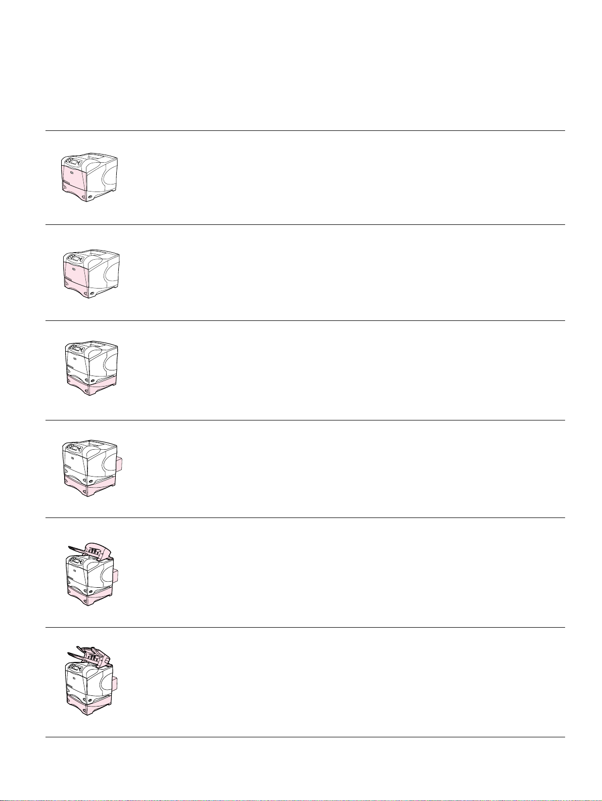
Printer configurations
The HP LaserJet 4200/4300 series printer is available in a total of 12 models.
Table 1. Product configurations
HP LaserJet 4200 series HP LaserJet 4300 series
Base model
n model
tn model
dtn model
● Q2425A
● 48 MB RAM, expandable to 416 MB
● one 100-sheet tray and one 500-sheet tray
● Q2426A
● 64 MB RAM, expandable to 416 MB
● one 100-sheet tray and one 500-sheet tray
● HP Jetdirect 10/100Base-TX print server card
for network connection
● Q2427A
● 64 MB RAM, expandable to 416 MB
● one 100-sheet tray and two 500-sheet trays
● HP Jetdirect 10/100Base-TX print server card
for network connection friend
● Q2428A
● 64 MB RAM, expandable to 416 MB
● one 100-sheet tray and two 500-sheet trays
● HP Jetdirect 10/100Base-TX print server card
for network connection
● duplexer for automatic two-sided printing
● Q2431A
● 64 MB RAM, expandable to 416 MB
● one 100-sheet tray and one 500-sheet tray
● Q2432A
● 80 MB RAM, expandable to 416 MB
● one 100-sheet tray and one 500-sheet tray
● HP Jetdirect 10/100Base-TX print server card
for network connection
● Q2433A
● 80 MB RAM, expandable to 416 MB
● one 100-sheet tray and two 500-sheet trays
● HP Jetdirect 10/100Base-TX print server card
for network connection
● Q2434A
● 80 MB RAM, expandable to 416 MB
● one 100-sheet tray and two 500-sheet trays
● HP Jetdirect 10/100Base-TX print server card
for network connection
● duplexer for automatic two-sided printing
dtns model
dtnsL model
● Q2446A
● 64 MB RAM, expandable to 416 MB
● one 100-sheet tray and two 500-sheet trays
● HP Jetdirect 10/100Base-TX print server card
for network connection
● duplexer for automatic two-sided printing
● 500-sheet stacker output accessory
● Q2447A
● 64 MB RAM, expandable to 416 MB
● one 100-sheet tray and two 500-sheet trays
● HP Jetdirect 10/100Base-TX print server card
for network connection
● duplexer for automatic two-sided printing
● 500-she et sta ple r/st acker output access ory
● Q2435A
● 80 MB RAM, expandable to 416 MB
● one 100-sheet tray and two 500-sheet trays
● HP Jetdirect 10/100Base-TX print server card
for network connection
● duplexer for automatic two-sided printing
● 500-sheet stacker output accessory
● Q2448A
● 80 MB RAM, expandable to 416 MB
● one 100-sheet tray and two 500-sheet trays
● HP Jetdirect 10/100Base-TX print server card
for network connection
● duplexer for automatic two-sided printing
● 500-sheet stapler/stacker output accessory
Q2431-90912 Chapter 1 Printer description 3
Page 24

Model and serial numbers
The model number and printer serial number are listed on an identification label located under
the top cover on the right side of the printer. The model number is alphanumeric, such as
Q2431A for the HP LaserJet 4200/4300 products.
The serial number contains information about the country/region of origin, the revision level, the
production code, and the production number of the printer. An example of a serial number is
USBB123456.
The label also contains power rating and regulatory information as shown in figure 1.
Figure 1. Sample model and serial number label
4 Printer description Q2431-90912
Page 25

Site requirements
The following environmental specifications must be maintained to ensure the correct operation of
the printer. Consider the following points before installing the printer:
● Install in a well-ventilated, dust-free area.
● Install on a hard, flat, continuous surface, with all four printer feet level. Do not install
on carpet or other soft surfaces.
● Make sure that adequate power is supplied. Printer circuit requirements are listed in
table 4 on page 8. Uninterruptable power supplies (UPSs) are not recommended.
● Install where temperature and humidity are stable, away from water sources,
humidifiers, air conditioners, refrigerators, or other major appliances. See table 6 on
page 8 for temperature and humidity ranges.
● Install awa y from direct sunlight, open flames, or ammonia fumes. If the printer is
placed near a window, make sure the window has a curtain or blind to block direct
sunlight.
● Install with enough space around the printer for access and ventilation.
● Install away from the direct flow of exhaust from air ventilation systems.
Printer specifications
Install the printer with enough space around it to open trays and bins, install toner, and perform
maintenance. The printer needs 101 mm (4 inches) of ventilation space on the left side (fan side)
and at the rear of the printer.
Q2431-90912 Chapter 1 Printer description 5
Page 26
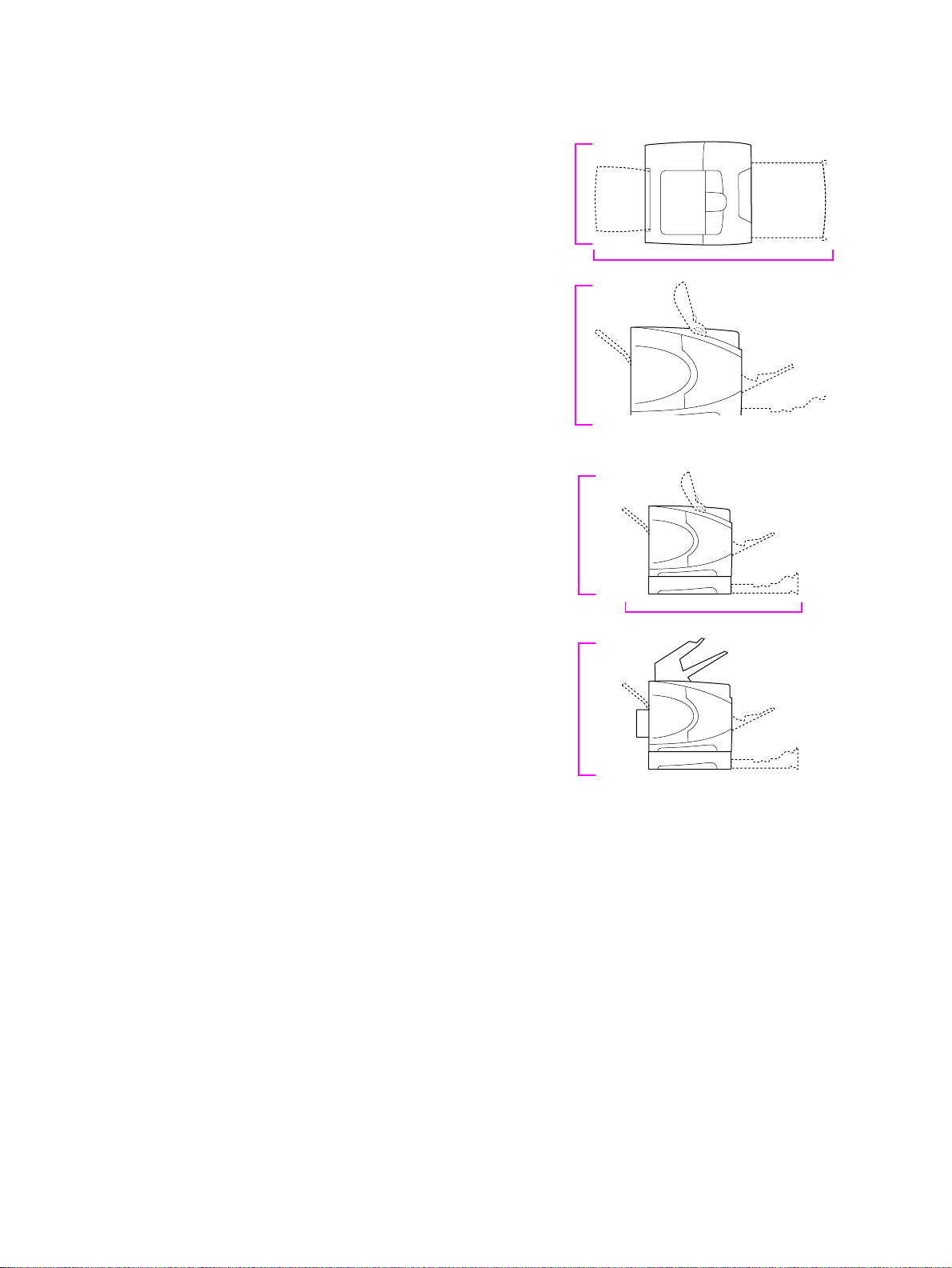
Physical dimensions
HP LaserJet 4200/4200n/4200tn/
4200dtn/4200dtns/4200dtnsL
Maximum length with trays and rear output bin open
HP LaserJet 4300/4300n/4300tn/
4300dtn/4300dtnsL
HP LaserJet 4200/4200n/4300/4300n
(top cover open)
HP LaserJet 4200tn/4 200 dtn/
4300tn/4300dtn
(top cover open)
HP LaserJet 4200dtns/4200dtnsL/
4300dtns/4300dtnsL
412 mm
(16.2 inches)
1,045 mm (41.1 inches)
547 mm
(21.5 inches)
670 mm
(26.4 inches)
1,045 mm (41.1 inches)
740 mm
(29.1 inches)
Figure 1. Printer physical dimensions
6 Printer description Q2431-90912
Page 27

Printer weights (without print cartridge)
Table 2. Printer weights
HP LaserJet 4200/4200n printers 20 kg (45 lb)
HP LaserJet 4200tn printer 27 kg (60 lb)
HP LaserJet 4200dtn printer 30 kg (66 lb)
HP LaserJet 4200dtns printer 33 kg (73 lb)
HP LaserJet 4200dtnsL printer 34 kg (76 lb)
HP LaserJet 4300/4300n printers 21 kg (46 lb)
HP LaserJet 4300tn printer 28 kg (61 lb)
HP LaserJet 4300dtn printer 30 kg (66 lb)
HP LaserJet 4300dtns printer 33 kg (73 lb)
HP LaserJet 4300dtnsL printer 34 kg (76 lb)
Environmental specifications
CAUTION P ower requirements are based on the country/region in which the printer is sold. Do not convert
operating voltages. Converting operating voltages can damage the printer and void the product
warranty.
Table 3. Power consumption
Printer model
Power consumption (average, in watts)
Printing Standby PowerSave
HP LaserJet 4200 580 (35 ppm) 21 20.4 .07
HP LaserJet 4200n 580 (35 ppm) 22 20.7 .07
HP LaserJet 4200tn 580 (35 ppm) 23 21.8 .07
HP LaserJet 4200dtn 580 (35 ppm) 24 24.2 .07
HP LaserJet 4200dtns 580 (35 ppm) 26 24.1 .07
HP LaserJet 4200dtnsL 580 (35 ppm) 26 at least 24.2 .07
HP LaserJet 4300 685 (45 ppm) 21 21.0 .07
HP LaserJet 4300n 685 (45 ppm) 23 22.7 .07
HP LaserJet 4300tn 685 (45 ppm) 24 22.6 .07
HP LaserJet 4300dtn 685 (45 ppm) 26 24.0 .07
HP LaserJet 4300dtns 685 (45 ppm) 26 24.5 .07
HP LaserJet 4300dtnsL 685 (45 ppm) 27 at least 24.9 .07
1. Values are subject to change. See http://www.hp.com/support/lj4200 or http://www.hp.com/support/lj4300
for current information.
2. PowerSa ve default activation time is 30 minutes.
1
2
Off
Q2431-90912 Chapter 1 Printer description 7
Page 28

Table 4. Circuit requirements
HP LaserJet 4200 series
110-volt models 220-volt models
HP LaserJet 4300 series
Power requirements 110 to 127 volt s(+/-10 percent)
50/60 Hz (+/-2 Hz)
Rated short-term current for a typical
8.2 amps 3.3 amps
product
220 to 240 volts (+/-10percent)
50/60 Hz (+/-2 Hz)
Table 5. Acoustic ratings
Sound power level
Printing, 35 ppm (HP LaserJet 4200 series)
Printing, 45 ppm (HP LaserJet 4300 series)
PowerSave
SPL-Bystander position
Printing, 35 ppm (HP LaserJet 4200 series)
Printing, 45 ppm (HP LaserJet 4300 series)
PowerSave
Values are subject to change. See http://www.hp.com/support/lj4200 or http://www.hp.com/support/lj4300 for
current information.
Declared per ISO 9296
L
=6.8bels(A)
WAd
L
=7.0bels(A)
WAd
L
=4.0bels(A)
WAd
Declared per ISO 9296
L
=54dB(A)
pAm
L
=56dB(A)
pAm
L
= 27 dB (A)
pAm
Table 6. General specifications
Description HP LaserJet 4200 HP LaserJet 4300
Operating tempera ture 10° to 32° C(50° to 90° F) 10° to 32° C (50° to 90° F)
Relative humidity 20 percent to 80 percent 20 percent to 80 percent
Speed, in pages per minute
(ppm)
Expandable memory Up to 416 MB total, combining
Up to 35 ppm, letter-size paper
Up to 33 ppm, A4-size paper
standard and accesso ry memory
DIMMs
Up to 45 ppm, letter-size paper
Up to 43 ppm, A4 -size paper
Up to 416 MB total, combining
standard and accessory memory
DIMMs
8 Printer description Q2431-90912
Page 29

Paper specifications
HP LaserJet 4200/4300 printers produce excellent print quality. This printer accepts a variety of
print media, such as cut-sheet paper (including recycled paper), envelopes, labels,
transparencies, and custom-size paper. Paper properties such as weight, grain, and moisture
content are important factors that affect printer performance and output quality.
The printer can use a variety of paper and other print media in accordance with the following
guidelines. Media that does not meet these guidelines can cause the following problems:
● poor print quality
● more jams
● premature wear on the printer, requiring repair
Note For best results, use only high-quality media, such as HP-brand paper and print media.
Hewlett-Packard Company cannot recommend the use of other brands. Because they are not HP
products, HP cannot influence or control their quality. To order HP quality papers and supplies,
go to http://www.hp.com or visit your local HP authorized reseller.
It is possible for paper to meet all of the guidelines specified here and still not produce satisfactory
results. This might be the result of improper handling, unacceptable temperature and humidity
levels, or other variables over which Hewlett-Packard has no control.
Before purchasing a large quantity of paper, make sure that it meets the requirements specified
here and in the HP LaserJet Printer Family Print Media Guide. Go to
http://www.hp.com/support/ljpaperguide for more information. Always test paper before
purchasing a large quantity.
CAUTION Using media that is outside HP specifications can cause problems for the printer, requiring repair.
This repair is not covered by the Hewlett-Packard warranty or service agreements.
This section provides information about types of media:
● Supported sizes and weights of media
● Supported types of paper
● Guidelines for using paper
● Paper weight equivalents
● Labels
● Overhead transparencies
● Env elopes
● Card stock and heavy paper
Q2431-90912 Chapter 1 Printer description 9
Page 30

Supported sizes and weights of media
Note The printer always prints at half speed from tray 1. The printer also prints at half speed from all
other trays when printing on media sizes other than letter, legal, and A4.
Table 7. Tray 1 Media specifications
Size Dimensions
Letter 216 by 279 mm
(8.5 by 11 inches)
A4 210 by 297 mm
(8.3 by 11.7 inches)
Legal 216 by 356 mm
(8.5 by 14 inches)
Executive 184 by 267 mm
(7.3 by 10.5 inches)
A5 148 by 210 mm
(5.8 by 8.3 inches)
B5 (ISO) 176 by 250 mm
(6.9 by 9.8 inches)
B5 (JIS) 182 by 257 mm
(7.2 by 10.1 inches)
Executive (JIS) 216 by 330 mm
(8.5 by 13 inches)
1
Weight Capacity
60 to 200 g/m
(16to53lb)
2
100 sheets of 75-g/
2
m
(20-lb) paper
2
Double postcard (JIS) 148 by 200 mm
(5.8 by 7.9 inches)
16K 197 by 273 mm
(7.8 by 10.8 inches)
Custom
Envelope
Commercial #10
Envelope
DL ISO
Envelope
C5 ISO
Envelope
B5 ISO
Envelope
Monarch #7-3/4
Transparencies (for
monochrome LaserJet
printers only)
3
Minimum:
76 by 127 mm
(3 by 5 inches)
Maximum:
216 by 356 mm
(8.5 by 14 inches)
105 by 241 mm
(4.1 by 9.5 inches)
110 by 220 mm
(4.3 by 8.7 inches)
162 by 229 mm
(6.4 by 9.0 inches)
176 by 250 mm
(6.9 by 9.8 inches)
98 by 191 mm
(3.9 by 7.5 inches)
Minimum:
76 by 127 mm
(3 by 5 inches)
75 to 105 g/m
(20to28lb)
Thickness:
0.099 to 0.114 mm
(0.0039 to 0.0045 inch)
2
10 envelopes
50 transparencies
Maximum:
216 by 356 mm
(8.5 by 14 inches)
10 Printer description Q2431-90912
Page 31

Table 7. Tray 1 Media specifications (continued)
Labels Minimum:
76 by 127 mm
(3 by 5 inches)
Thickness:
0.127 to 0.229 mm
(0.005 to 0.009 inch)
Maximum:
216 by 356 mm
(8.5 by 14 inches)
1. The printer supports a wide range of sizes. Check the printer software for supported sizes.
2. Capacity can vary depending on paper weight and thickness, as well as environmental conditions.
3. All sizes can be stacked, but only letter, legal, and A4 can be stapled.
Table 8. Tray 2 and 500-sheet feeder media specifications
Size Dimensions
Letter 216 by 279 mm
(8.5 by 11 inches)
A4 210 by 297 mm
(8.3 by 11.7 inches)
Executive 184 by 267 mm
(7.3 by 10.5 inches)
Legal 216 by 356 mm
(8.5 by 14 inches)
B5 (JIS) 182 by 257 mm
(7.2 by 10.1 inch)
1
60 to 120 g/m
(16to32lb)
Weight Capacity
2
500 sheets of 75-g/m
(20-lb) paper
50 labels
2
2
A5 148 by 210 mm
(5.8 by 8.3 inches)
Custom
3
Minimum:
148 by 210 mm
(5.8 by 8.3 inch)
Maximum:
216 by 356 mm
(8.5 by 14 inches)
1. The printer supports a wide range of sizes. Check the printer software for supported sizes.
2. Capacity can vary depending on paper weight and thickness, as well as environmental conditions.
3. All sizes can be stacked, but only letter, legal, and A4 can be stapled.
Table 9. 1,500-sheet feeder media specifications
Size Dimensions Weight Capacity
Letter 216 by 279 mm
(8.5 by 11 inches)
A4 210 by 297 mm
(8.3 by 11.7 inches)
60 to 120 g/m
(16to32lb)
2
Legal 216 by 356 mm
(8.5 by 14 inches)
1. Capacity can vary depending on paper weight and thickness, as well as environmental conditions.
1,500 sheets of 75-g/m
(20-lb) paper
1
2
Q2431-90912 Chapter 1 Printer description 11
Page 32

Table 10. Duplex accessory media specifications
Size Dimensions Weight
Letter 216 by 279 mm
(8.5 by 11 inches)
A4 210 by 297 mm
(8.3 by 11.7 inches)
Executive 184 by 267 mm
(7.3 by 10.5 inches)
Legal 216 by 356 mm
(8.5 by 14 inches)
B5 (JIS) 182 by 257 mm
(7.2 by 10.1 inches)
A5 148 by 210 mm
(5.8 by 8.3 inches)
60 to 120 g/m
(16to32lb)
Table 11. Envelope feeder accessory
Size Dimensions Weight Capacity
Monarch #7-3/4 98 by 191 mm
(3.9 by 7.5 inches)
2
Commercial#10 105 by 241 mm
(4.1 by 9.5 inches)
DL ISO 110by 220 mm
(4.3 by 8.7 inches)
C5 ISO 162by 229 mm
(6.4 by 9.0 inches)
B5 ISO 176 by 250 mm
(6.9 by 9.8 inches)
75 to 105 g/m
(20to28lb)
2
75 envelopes
12 Printer description Q2431-90912
Page 33

Table 12 . Stacke r or stapler/stacker accessory
Size Dimensions
Stacker or stacker part of stapler/stacker only
Letter 216 by 279 mm
(8.5 by 11 inches)
A4 210 by 297 mm
(8.3 by 11.7 inches)
Executive 184 by 267 mm
(7.3 by 10.5 inches)
Legal 216 by 356 mm
(8.5 by 14 inches)
B5 (JIS) 182 by 257 mm
(7.2 by 10.1 inches)
A5 148 by 210 mm
(5.8 by 8.3 inches)
1
Weight Capacity
60 to 120 g/m
(16to32lb)
2
2
500 sheets of 75-g/m
2
(20-lb) paper
Custom
3
Minimum:
148 by 210 mm
(5.8 by 8.3 inches)
Maximum:
216 by 356 mm
(8.5 by 14 inches)
Stapler part of stapler/stacker only
Letter 216 by 279 mm
(8.5 by 11 inches)
A4 210 by 297 mm
(8.3 by 11.7 inches)
60 to 120 g/m
(16to32lb)
Legal 216 by 356 mm
(8.5 by 14 inches)
1. The printer supports a wide range of sizes. Check the printer software for supported sizes.
2. Capacity can vary depending on paper weight and thickness, as well as environmental conditions.
3. All sizes can be stacked, but only letter, legal, and A4 can be stapled.
Note The stacker and stapler/stacker do not support card stock.
Do not use the stapler/stacker to staple labels, card stock, or transparencies.
2
15 sheets of 75-g/m
2
(20-lb) paper
Q2431-90912 Chapter 1 Printer description 13
Page 34

Supported types of media
The printer supports the following types of paper and other print media:
● plain
● letterhead
● prepunched
● bond
● color
● rough
● preprinted
● transparency
● labels
● recycled
● card stock
● envelopes
Guidelines for using paper
For best results, use conventional 75- to 90-g/m2 (20- to 24-lb) paper. Make sure that the paper
is of good quality, and free of cuts, nicks, tears, spots, loose particles, dust, wrinkles, voids, and
curled or bent edges. If you are unsure what type of paper you are loading (such as bond or
recycled), check the label on the package of paper.
CAUTION Some paper might cause print-quality problems, jamming, or damage to the printer.
Symptom Problem with paper Solution
Poor print quality or toner
adhesion.
● Too moist, too rough, too smooth, or
embossed.
● Ragged edges.
● Faulty paper lot.
● Try another kind of paper, between
100 to 250 Sheffield, 4 to 6 percent
moisture content.
● Change the fuser mode. See “Print Quality
submenu” on page 46.
Dropouts, jamming, curl.
● Stored improperly. ● Store paper flat in its moisture-proof
wrapping.
Increased gray background
shading.
● Too heavy. ● Use lighter paper.
● Use a higher toner density setting. See
“Print Quality submenu” on page 46.
● Too smooth. ● Use less smooth paper.
Excessive curl.
Problems with feeding.
● Too moist, wrong grain direction, or short-
grain construction.
● Use the rear output bin.
● Turn the paper stack over in the tray.
● Use long-grain paper.
● Store paper in a drier environment.
● Change the fuser mode. See “Print Quality
submenu” on page 46.
Note Do not use letterhead paper that is printed with low-temperature inks, such as those used in some
types of thermography.
Do not use raised letterhead.
The printer uses heat and pressure to fuse toner to the paper. Make sure that any colored paper
or preprinted forms use inks that are compatible with the printer’s temperature of 230° C (446° F)
for 0.05 second.
Avoid using paper that has been damaged from being previously used in a printer or copier. (Do
not print on both sides of envelopes, transparencies, or labels.)
14 Printer description Q2431-90912
Page 35

Paper weight equivalence table
Use the following table to determine approximate equivalent points in weight specifications other
than U.S. bond weight. For e xample, to determine the equivalent of 20-lb U.S. bond weight paper
in U.S. cover weight, locate the bond weight (in row 3, second column) and scan across the row
to the cover weight (in the fourth column). The equivalent is 28 lb.
The shaded areas indicate a standard weight for that grade.
Table 13. Paper weight equivalents
U.S. post card1
thickness
(mm)
U.S. bond
weight (lb)
U.S. text/book
weight
16 41 22 27 33 37 60
2
(lb)
U.S. cover
weight (lb)
U.S. Bristol
weight (lb)
U.S. index
weight (lb)
U.S. tag weight
(lb)
Metric weight
(g/m2)
17 43 24 29 35 39
20 50
21 54 30 36 44 49
24 60
27 68 37 45 55 61
28 70
29 74 41 50 61 68
32 80
36 90 50 62 75 83 135
0.18 39
100 55 67 82 91 148
40 101 55 68 83 92
0.20 43 110
45 115 63 77 94 104
0.23 47 119
51 128 70 86 105 117
53 134 74 90
54 137 75 93 113
58 146
64
2
28 34 42 46 75
80
b
33 41 50 55 90
100
b
39 49 58 65 105
110
b
44 55 67 74 120
150
60 74 90 100 163
170
65 80 97 108 176
190
110 122 200
125 203
80 98 120 133 216
65 165 90 111 135 150 244
66 169 92 114 138 154 250
67 171 94 115
70 178 98
120 146 162 264
140 155 253
72 183 100 123 150 166 271
1. U.S. postcard measurements are approximate. Use for reference only.
2. Text and book grades actually calculate out to 51, 61, 71, and 81, but are standardized to book/text weights of 50, 60, 70, and 80.
Q2431-90912 Chapter 1 Printer description 15
Page 36

Labels
Use tray 1 to print labels. Labels are multiple-layer media that typically consists of a face sheet
(the printable surface), pressure-sensitive adhesive, and a liner (a carrier sheet coated with a
release agent). Labels used in the HP LaserJet printer must be specifically designed for laser
printers. If labels other than those compatible with laser printers are used, there is a significant
risk of labels peeling or of adhesive contamination that can severely damage the printer. All
materials in laser label stock must be compatible with the heat and pressure of the fusing
process.
CAUTION To avoid damaging the printer, use only labels that are recommended for use in laser printers.
Do not duplex labels or leave the printer default set to DUPLEX=ON.
Do not staple labels in the stapler/stacker .
Do not print on the same sheet of labels more than once. The printer might be damaged.
If you have problems printing labels, use tray 1 and open the rear output bin. When selecting
labels, consider the quality of each component.
● Adhesives: The adhesive material should be stable at 230° C (446° F) for 0.05
seconds (this is the printer’s maximum temperature).
● Arrangement: Use only labels with no exposed backing between them. Labels can
peel off sheets that have spaces between the labels, causing serious jams.
● Curl: Before printing, labels must lie flat with no more than 13 mm (0.5 inch) of curl
in any direction.
● Condition: Do not use labels that have wrinkles, bubbles, or other indications of
separation.
Overhead transparencies
Use tray 1 to print overhead transparencies. Overhead transparency film must be designed
specifically for use with monochrome laser printers. Photocopy transparency film might not be
compatible with laser printers because of higher temperature and stiffness requirements.
Overhead transparency film is very smooth and must have a topcoat to provide the proper
electrical and toner adhesion properties. A transparency that is made of poor materials or that is
too thin can easily melt in the fuser and damage the printer.
Overhead transparency materials must be compatible with the heat and pressure of the fusing
process.
CAUTION To avoid damaging the printer, use only transparencies that are recommended for use in
monochrome laser printers.
Do not attempt to duplex overhead transparencies or leave the printer default set to DUPLEX=ON.
Damage to the printer might result.
Do not staple transparencies in the stapler/stacker.
Transparencies used in the printer must be able to withstand the printer’s maximum temperature
of 230° C (446° F) for 0.05 seconds. Close the rear output bin to print transparencies to the top
output bin. If you have problems printing transparencies, use tray 1 and print to the top output
bin. Be sure to remove each transparency from the output bin as it prints to keep the
transparencies from sticking together.
16 Printer description Q2431-90912
Page 37

Envelopes
Bad
Good
Envelope construction
Envelope construction is critical. Envelope fold lines can vary considerably, not only between
manufacturers, but also within a box from the same manufacturer. Successful printing on
envelopes depends upon the quality of the envelopes.
When selecting envelopes, consider the following components. Many envelope manufacturers
are now making envelopes optimized for laser printers.
● Weight: The weight of the envelope paper should be 75 to 105 g/m
jamming might result.
● Construction: Before printing, envelopes should lie flat with less than 6 mm
(0.25 inch) curl, and should not contain air. (Envelopes that trap air might cause
problems.)
● Condition: Make sure that envelopes are not wrinkled, nicked, or otherwise
damaged.
● Sizes in tray 1: Use standard and custom sizes from 76 by 127 mm (3 by 5 inches)
to 216 by 356 mm (8.5 by 14 inches).
● Sizes in the optional envelope feeder: Standard sizes from
Monarch (98 by 191 mm, or 3.9 by 7.5 inches) to B5 (ISO) (176 by 250 mm, or
6.9 by 9.8 inches).
If you do not have an optional envelope feeder, alwa ys print envelopes from tray 1. If envelopes
curl or jam, try opening the rear output bin.
2
(20to28lb) or
CAUTION Do not duplex envelopes. Damage to the printer might result.
Do not send envelopes to the stacker or stapler/stacker. Damage to the stacker or stapler/stacker
might result.
Envelopes with double-side-seams
Double-side-seam construction has vertical seams at both ends of the envelope rather than
diagonal seams. This style might be more likely to wrinkle unless properly constructed. Be sure
the seam extends all the way to the corner of the envelope.
Envelopes with adhesive strips or flaps
Envelopes that are use a peel-off adhesive strip or with more than one flap that folds over to seal
must use adhesives compatible with the heat and pressure in the printer. The extra flaps and
strips might cause wrinkling, creasing, or jams.
construction
construction
Q2431-90912 Chapter 1 Printer description 17
Page 38

Envelope margins
The following table gives typical address margins for a Commercial #10 or DL envelope.
Type of address Top margin Left margin
Return address 15 mm (0.6 inches) 15 mm (0.6 inches)
Delivery address 51 mm (2 inches) 89 mm (3.5 inches)
Hint For the best print quality, position margins no closer than 15 mm (0.6 inch) from the edges of the
envelope.
Envelope storage
Proper storage of envelopes helps contribute to good print quality. Envelopes should be stored
flat. If air is trapped in an envelope, creating an air bubble, then the envelope might wrinkle
during printing.
Card stock and heavy paper
Many types of card stock can be printed from tray 1, including index cards and postcards. Some
card stock performs well because its construction is better suited for feeding through a laser
printer.
2
For optimum printer performance, do not use paper that is heavier than 200 g/m
or 120 g/m
2
(32 lb) in other trays. Paper that is too heavy might cause misfeeds, stacking
problems, jams, poor toner fusing, poor print quality, or excessive mechanical wear.
(53 lb) in tra y 1
The stacker and stapler/stacker do not support card stock.
CAUTION Do not attempt to duplex card stock or paper heavier than 120 g/m2(35 lb), or leave the printer
default set to DUPLEX=ON. Damage to the printer might result.
Do not attempt to use the stacker or stapler/stacker with card stock.
Note Printing on heavier paper might be possible if the tray is not filled to capacity, and short-grain
paper with a smoothness rating of 100 to 180 Sheffield is used.
Card stock construction
● Smoothness: Card stock should have smoothness in the range of
100 to 180 Sheffield.
● Construction: Card stock should lie flat with less than 5 mm (0.2 inch) of curl. It
should be short-grain paper to improve feeding and reduce wear on the printer.
● Condition: Make sure that card stock is not wrinkled, nicked, or otherwise
damaged.
● Sizes: Use only card stock within the following size ranges:
• minimum: 76 by 127 mm (3 by 5 inches)
• maximum: 216 by 356 mm (8.5 by 14 inches)
Before loading card stock in tray 1, make sure that it is regular in shape and not damaged. Also,
make sure that the cards are not stuck together.
Card stock guidelines
● If cards curl or jam, try printing from tray 1 and opening the rear output bin.
● Set margins at least 6 mm (0.24 inch) away from the edges of the paper.
18 Printer description Q2431-90912
Page 39

Types of print media to avoid
The following characteristics can affect the performance of the HP LaserJet 4200/4300 printer
unless the paper or other print media used is specifically designed to work with HP LaserJet
printers.
● Print media that is very rough, highly textured, or heavily embossed.
● Multipart forms.
● Print media that offsets materials or discolors.
● Print media that is damaged, curled, wrinkled, or irregularly shaped.
● Paper that is extremely shiny or glossy.
● Paper, labels, envelopes, or transparencies that produce undesirable emissions or
melt when exposed to a fusing temperature of 230° C (446° F) for 0.05 second.
● Media coatings, dyes, or inks that produce undesirable emissions or melt when
exposed to a fusing temperature of 230° C (446° F) for 0.05 second.
● Envelopes that have an open flap with the adhesive exposed so that closing the flap
seals the envelope.
● Envelopes with clasps, snaps, tie strings, windows, or synthetic materials. These
materials can severely damage the printer.
● Envelopes that are not square, straight, or constructed correctly. See “Envelope
construction” on page 17.
● Envelopes with a basis weight less than 60 g/m
lb).
● Envelopes with baggy construction or folds that are not sharply creased.
2
(16 lb) or greater than 105 g/m2 (28
Note Some media types might not work in the printer because of differences in manufacturer
specifications or environmental conditions.
Q2431-90912 Chapter 1 Printer description 19
Page 40

Safety information
Print cartridge and toner safety
Handling and storage
For information about handling and storing toner, see section 7 in the material safety data sheet
(MSDS) at the http://www.hp.com/go/msds website.
First aid measures
For information about toner safety, see section 4 in the material safety data sheet (MSDS) at the
http://www.hp.com/go/msds website.
Clothing contact
Note Toner can stain clothing. Hot water or heat (from a clothes dryer) can cause toner to melt and
permanently fuse into clothing.
Clothing is best cleaned by removing as much toner as possible with a dry tissue, and then
washing with cold water. Air-dry clothing.
Additional information
The print cartridge Material Safety Data Sheet (MSDS) can be obtained by contacting HP at the
http://www.hp.com/go/msds website.
Laser safety
Do not open the laser scanner assembly. Avoid direct exposure to the laser beams.
WARNING! Using controls, making adjustments, bypassing safety switches, or performing procedures other
than those specified in this service manual can result in exposure to hazardous radiation.
Laser safety statement (U.S.)
The Center for Devices and Radiological Health (CDRH) of the U.S. Food and Drug
Administration has implemented regulations for laser products manufactured since
August 1, 1976. Compliance is mandatory for products marketed in the United States. The
printer is certified as a “Class 1” laser product under the U.S. Department of Health and Human
Services (DHHS) Radiation Perf ormance Standard according to the Radiation Control for Health
and Safety Act of 1968. Because radiation emitted inside the printer is completely confined within
protective housings and external covers, the laser beam cannot escape during any phase of
normal user operation.
WARNING! Using controls, making adjustments, or performing procedures other than those specified in this
user guide can result in exposure to hazardous radiation.
20 Printer description Q2431-90912
Page 41

EMI statement (Korea)
VCCI statement (Japan)
Q2431-90912 Chapter 1 Printer description 21
Page 42

Laser statement (Finland)
Luokan 1 laserlaite
Klass 1 Laser Apparat
HP LaserJet 4200 series, 4300 series laserkirjoitin on käyttäjän kannalta turvallinen luokan 1
laserlaite. Normaalissa käytössä kirjoittimen suojakotelointi estää lasersäteen pääsyn laitteen
ulkopuolelle. Laitteen turvallisuusluokka on määritetty standardin EN 60825-1 (1994) mukaisesti.
Varoitus!
Laitteen käyttäminen muulla kuin käyttöohjeessa mainitulla tavalla saattaa altistaa käyttäjän
turvallisuusluokan 1 ylittävälle näkymättömälle lasersäteilylle.
Varning!
Om apparaten används på annat sätt än i bruksanvisning specificerats, kan användaren utsättas
för osynlig laserstrålning, som överskrider gränsen för laserklass 1.
HUOLTO
HP LaserJet 4200 series, 4300 series -kirjoittimen sisällä ei ole käyttäjän huollettavissa olevia
kohteita. Laitteen saa avata ja huoltaa ainoastaan sen huoltamiseen koulutettu henkilö.
Tällaiseksi huoltotoimenpiteeksi ei katsota väriainekasetin vaihtamista, paperiradan puhdistusta
tai muita käyttäjän käsikirjassa lueteltuja, käyttäjän tehtäväksi tarkoitettuja ylläpitotoimia, jotka
voidaan suorittaa ilman er ikoist yökaluja.
Varo!
Mikäli kirjoittimen suojakotelo avataan, olet alttiina näkymättömälle lasersäteilylle laitteen ollessa
toiminnassa. Älä katso säteeseen.
Varning!
Om laserprinterns skyddshölje öppnas då apparaten är i funktion, utsättas användaren för
osynlig laserstrålning. Betrakta ej strålen.
Tiedot laitteessa käytettävän laserdiodin säteilyominaisuuksista:
Aallonpituus 775-7 95 nm
Teho 5 mW
Luokan 3B laser
22 Printer description Q2431-90912
Page 43

Regulatory information
FCC regulations
This equipment has been tested and found to comply with the limits for a Class B digital device,
pursuant to Part 15 of the FCC rules. These limits are designed to provide reasonable protection
against harmful interference in a residential installation. This equipment generates, uses, and
can radiate radio frequency energy . If this equipment is not installed and used in accordance with
the instructions, it may cause harmful interference to radio communications. However , there is no
guarantee that interference will not occur in a particular installation. If this equipment does cause
harmful interference to radio or television reception, which can be determined by turning the
equipment off and on, the user is encouraged to try to correct the interference by one or more of
the following measures:
● Reorient or relocate the receiving antenna.
● Increase separation between equipment and receiver.
● Connect equipment to an outlet on a circuit different from that to which the receiver
is located.
● Consult your dealer or an experienced radio/TV technician.
Note Any changes or modifications to the printer that are not expressly approved by HP could void the
user’s authority to operate this equipment.
Use of a shielded interface cable is required to comply with the Class B limits of Part 15 of FCC
rules.
Attaching a network interface cable to the printer’s LAN connector(s) changes the Class B rating
to Class A. For more information see the supplementary ibformation in the “Declaration of
Conformity” on page 26.
Q2431-90912 Chapter 1 Printer description 23
Page 44

Environmental product stewardship program
Protecting the environment
Hewlett-Packard Company is committed to providing quality products in an environmentally
sound manner. This product has been designed with several attributes to minimize impacts on
our environment.
Energy consumption
Energy usage drops while in PowerSave mode, which saves natural resources and saves money
without affecting the high performance of this product. This product qualifies for E
which is a voluntary program to encourage the development of energy-efficient office products.
NERGY STAR
E
As an E
meets E
http://www.energystar.gov website.
®
is a U.S. registered service mark of the U.S. Environmental Protection Agency.
NERGY STAR
NERGY STAR
®
Partner, Hewlett-Packard Company has determined that this product
®
Guidelines for energy efficiency. For more information, see the
NERGY STAR
®
Toner consumption
EconoMode uses significantly less toner, which might extend the life of the print cartridge.
Paper use
This product’s optional automatic duplex feature (two-sided printing), and n-up printing (multiple
pages printed on one page) capability can reduce paper usage and the resulting demands on
natural resources.
Plastics
,
Plastic parts over 25 grams are marked according to international standards that enhance the
ability to identify plastics for recycling purposes at the end of the product’s life.
HP LaserJet printing supplies
In many countries/regions, this product’s printing supplies (for example the print cartridge, drum,
and fuser) can be returned to HP through the HP Printing Supplies Returns and Recycling
Program. An easy-to-use and free take back program is available in more than 48 countries/
regions. Multi-lingual program information and instructions are included in every new
HP LaserJet print cartridge and supplies package.
Paper
This product is capable of using recycled papers when the paper meets the guidelines outlined in
the HP LaserJet Printer Family Print Media Guide.
(See http://www.hp.com/support/ljpaperguide.) This product is suitable for the use of recycled
paper according to DIN 19309.
24 Printer description Q2431-90912
Page 45

Material restrictions
This HP product does not contain added mercury.
This HP product contains lead in solder that might require special handling at end-of-life.
This HP product does not contain batteries.
For recycling information, you can contact http://www.hp.com/recycle, your local authorities, or
the Electronics Industries Alliance at http://www.eiae.org.
Material Safety Data Sheet
Material Safety Data Sheets (MSDS) can be obtained by contacting the HP LaserJet Supplies
website at http://www.hp.com/hpinfo/community/environment/productinfo.
For more information
To obtain more information about the following environmental topics, visit
http://www.hp.com/go/environment or http://www.hp.com/hpinfo/community/environment:
● product environmental profile sheet for this and many related HP products
● HP’s commitment to the environment
● HP’s environmental management system
● HP’s end-of-life supplies return and recycling program
● MSDS
HP Printing Supplies Returns and Recycling program
information
Since 1990, the HP Printing Supplies Returns and Recycling program has collected millions of
used LaserJet print cartridges that otherwise might have been discarded in the world’s landfills.
The HP LaserJet print cartridges and supplies are collected and bulk shipped to our resource
and recovery partners who disassemble the cartridge. After a thorough quality inspection,
selected parts are reclaimed for use in new print cartridges. Remaining materials are separated
and converted into raw materials for use by other industries to make a variety of useful products.
U.S. returns
For a more environmentally responsible return of used cartridges and supplies, HP encourages
the use of bulk returns. Simply bundle two or more cartridges together and use the single, prepaid, pre-addressed UPS label that is supplied in the package. For more information in the U.S.,
call (1-800-340-2445) or visit the HP LaserJet Supplies website at http://www.hp.com/recycle.
Non-U.S. returns
Non-U.S. customers should call their local HP sales and service office or visit the
http://www.hp.com/recycle website for further information regarding availability of the
HP Supplies Returns and Recycling Program.
Q2431-90912 Chapter 1 Printer description 25
Page 46

Declarations of Conformity
Declaration of Conformity
according to ISO/IEC Guide 22 and EN 45014
Manufacturer’s Name: Hewlett-Packard Company
Manufacturer’s Address: 11311 Chinden Boulevard
declares that the product
Product Name: HP LaserJet 4200 series
Regulatory Model Numbers: BO ISB-0203-00
Product Options: ALL
conforms to the following Product Specifications:
Safety: IEC 60950:1999 / EN 60950:2000
EMC: CI SP R 22:1993+A 1+A2 / EN 55022:1994+A1+A2 Class B
Supplementary Information:
The product herewith complies with the requirements of the EMC Directive 89/336/EEC and the Low Voltage Directive 73/23/EEC, and carries the
CE-Marking accordingly.
1)
The product was tested in a typical configuration with Hewlett-Packard Per sonal Computer Syst em s.
2)
The product includes LAN (local area network) options. When the interface cable is attached to LAN connectors, the product meets the
requirements of EN55022 Class A in which case the following applies: Warning
product may cause radio interference in which case a user may be required to take adequate measures.
3)
This Device complies with Part 15 of the FCC Rules. Operation is subject to the following two Conditions: (1) this device may not cause
harmful interference, and (2) this device must accept any interference received, including interference that may cause undesired operation.
IEC 60825-1:1993+A1 / EN 60825-1+A11 Class 1 Laser/LED Product
GB4943:1995
EN 61000-3-2:1995 / A14
EN 61000-3-3:1995
EN 55024:1998
FCC Title 47 CFR, Part 15 Class B
AS /NZS 3548:1995+A1+A2 GB9254:1998
Boise, Idaho 83714-1021, USA
HP LaserJet 4300 series
BOISB-0204-00
1)
3
/ ICES-003, Issue 3
*2)
— This is a class A product. In a domestic environment, this
Boise, Idaho, USA
17 April 2002
For regulatory topics ONLY, contact:
Australia Contact: Product Regulations Manager, Hewlett-Packard Australia Ltd., 31-41 Joseph Street, Blackburn, Victoria 3130, Australia
Europe Contact: Your Local Hewlett-Packard Sales and Service Office or Hewlett-Packard Gmbh, Department HQ-TRE / Standards
Europe, Herrenberger Straße 130, D-71034 Böblingen (FAX: +49-7031-14-3143)
USA Contact: Product Regulations Manager, Hewlett-Packard Company, PO Box 15, Mail Stop 160, Boise, ID 83707-0015 (Phone:
208-396-6000)
Canadian DOC regulations
Complies with Canadian EMC Class B requirements.
Conforme à la classe B des normes canadiennes de compatibilité électromagnétique (CEM).
26 Printer description Q2431-90912
Page 47

2 Service approach
Contents
Service approach . . . . . . . . . . . . . . . . . . . . . . . . . . . . . . . . . . . . . . . . . . . 28
Parts and supplies. . . . . . . . . . . . . . . . . . . . . . . . . . . . . . . . . . . . . . . . . . . 28
Ordering information . . . . . . . . . . . . . . . . . . . . . . . . . . . . . . . . . . . . . . 28
Related documentation and software . . . . . . . . . . . . . . . . . . . . . . . . . 28
Support . . . . . . . . . . . . . . . . . . . . . . . . . . . . . . . . . . . . . . . . . . . . . . . . 28
HP-authorized resellers and support . . . . . . . . . . . . . . . . . . . . . . . 29
HP service agreements . . . . . . . . . . . . . . . . . . . . . . . . . . . . . . . . . 29
HP PartnerCare . . . . . . . . . . . . . . . . . . . . . . . . . . . . . . . . . . . . . . . 29
Worldwide service and support offices. . . . . . . . . . . . . . . . . . . . . . 30
Print-cartridge information. . . . . . . . . . . . . . . . . . . . . . . . . . . . . . . . . . 31
Refilled print cartridges. . . . . . . . . . . . . . . . . . . . . . . . . . . . . . . . . . 31
Recycling print cartridges. . . . . . . . . . . . . . . . . . . . . . . . . . . . . . . . 31
Returns. . . . . . . . . . . . . . . . . . . . . . . . . . . . . . . . . . . . . . . . . . . . . . 31
Hewlett-Packard limited warranty statement. . . . . . . . . . . . . . . . . . . . . . . 32
Limited warranty for toner cartridge life . . . . . . . . . . . . . . . . . . . . . . . . 33
Q2431-90912 Chapter 2 Service approach 27
Page 48

Service approach
Repair of the printer normally begins with the use of the printer’s internal diagnostics in
conjunction with the troubleshooting procedures that are described in chapter 7. When a faulty
part is located, repair is generally accomplished by assembly-level replacement of fieldreplaceable units (FRUs) (listed in chapter 8). Some mechanical assemblies might be repaired at
the subassembly level. Hewlett-Packard does not support replacement of components on printed
circuit boards.
Parts and supplies
Ordering information
Chapter 8 of this manual contains FRU and accessory part numbers. Replacement parts can be
ordered from the HP Services. Go to http://www.hp.com/go/parts for information about ordering
service parts in your area. Go to http://www.hp.com/go/partsinfo for the online HP service parts
identification tool (HP PartSurfer).
Use only the accessories that are specifically designed for this printer. Order accessories from
an authorized service or support provider, or online at http://www.hp.com (for more information,
see chapter 8).
Related documentation and software
Order documentation and software from the sites listed in table 14.
Support
Table 14. Technical support websites
HP Connect Online.
(for HP partners)
HP Customer Care Online.
Software drivers, support
documentation, and answers to
frequently asked questions.
HP Technical Training.
Classes and schedules.
Parts.
Parts information.
http://www.connect-online.hp.com
HP Connect Online is an Internet site that is created
exclusively for our partners. You can easily find all the HP
information tha t y ou n eed for your daily business . A nd y ou
can get it earlier than from any other site
http://www.hp.com
Select your country/region in the “select a country or
region” field on the web page. Select the support block.
USA: http://www.partner.americas.hp.com
Canada: http://www.canada.hp.com
Asia: http://partnercare.asiapac.hp.com
Latin America: http://www.conecta.latinamerica.hp.com
Ordering: http://www.hp.com/go/parts
Identifying: http://www.hp.com/go/partsinfo
.
28 Service approach Q2431-90912
Page 49

HP provides free telephone support during the product warranty period. When you call, you will
be connected to a responsive team waiting to help you. For the number you should call in your
country/region, see the support sheet that came in the box with your printer. Before calling have
the following information available:
● product name (for example, HP LaserJet 4300 dtns)
● product serial number (found on the underside of the control-panel door.
● the date of purchase of your printer and a description of the problem you are
experiencing
Test the software installation. Attempt to print a test page from the software program. Try
reinstalling the software. If reinstalling the software does not correct the problem, see the
Readme file on the CD-ROM that came with the printer, or call the phone number for your
country/region (phone numbers are listed on the support sheet that came in the box with the
printer). You can also find answers to frequently asked questions at the following websites:
● htpp//:www.hp.com/support/lj4200
● htpp//:www.hp.com/support/lj4300
HP-authorized resellers and support
To locate HP-authorized resellers and support, call (1) (800) 243-9816 in the U.S. or
(1) (800) 387-38 67 in Cana da. See “Worldwide service and support offices” on page 30 for
areas outside of North America.
HP service agreements
For information about HP service agreements, call (1) (800) 743-8305 in the U.S. or (1) (800)
268-1221 in Canada.
HP PartnerCare
You can use the following information to contact HP PartnerCare:
● for PartnerShip Web, http://www.partner.americas.hp.com
● for Connect Online, http://www.connect-online.hp.com
● for Asia Pacific countries/regions, http://partnercare.asiapac.hp.com
● for Canada Partner, http://www.canada.hp.com
● for Latin America, http://www.conecta.latinamerica.hp.com
Q2431-90912 Chapter 2 Service approach 29
Page 50

Worldwide service and support offices
● F or the U.S., call (1) (208) 323-2551 Monday through Friday from 6 A.M. to 6 P.M.,
Mountain time.
● F or Canada, call (1) (905) 206-4663 or (1) (800) 387-3867 Monday through Friday
from 8
● F or customers outside of North America, use the following list and call the
appropriate telephone number for the country/region.
Europe
A.M. to 8 P.M., Mountain time.
● Austria: 43 (0)810 00 6080
● Belgium
Dutch: 32 (0)2 626-8806
French: 32 (0)2 626-8806
● Czech Republic: 42 (0)2 6130 7310
● Denmark: +45 39 29 4099
● International English: +44 (0)207 512 52 02
● Finland: 358 (0)203 47 288
● France: 33 (0)1 43 62 34 34
● Germany: 49 (0)180 52 58 143
● Greece: +30 (0)1 619 64 11
● Hungary: +36 (0)1 382-1111
● Ireland: +353 (0)1 662 5525
● Italy: 39 02 264 10350
Africa and Middle East
● Egypt: +202 7956222
● International English: +44 (0)207 512 52 02
● Israel: +972 (0)9 9524848
● South Africa
Inside RSA: 086 000 1030
Outside RSA: +27-11 258 9301
Asia-Pacific
● Netherlands: 31 (0)20 606 8751
● Norway: 47 22 11 6299
● Poland: +48 22 865 98 00
● Portugal: 351 21 3176333
● Romania: +40 1 315 44 42 (or 01 3154442)
● Russian Federation
Moscow: +7 095 797 3520
St. Petersburg: +7 812 346 7997
● Spain: +34 902 321 123
● Sweden: +46 (0)8 619 2170
● Switzerland: +41 (0)848 80 11 11
● Turkey: +90 212 221 69 69
● Ukraine: +7 (380-44) 490-3520
● U.K.: +44 (0)207 512 52 02
● United Arab Emirates, Bahrain, Jordan, Kuwait,
Lebanon, Oman, Palestine, Qatar, Saudi Arabia,
and Yemen: 971 4 883 8454
● Australia: (03) 8877 8000
● China: +86 (0)10 6564 5959
● Hong Kong SAR: +85 (2) 2802 4098
● India: +91 11 682 6035
● Indonesia: +62 (21) 350-3408
● Japan: +81 3 3335-8333
● Republic of Korea
● Malaysia: +60 (3) 295 2566
● New Zealand: +64 (9) 356 6640
● Philippines: +63 (2) 867 3551
● Singapore: +65 272 5300
● Taiwan: +886 (2) 2717 0055
● Thailand: +66 (2) 661 4000
● Vietnam: +84 (0) 8 823 4530
Seoul: +82 (2) 3270-0700
Outside Seoul: 080 999-0700
Latin America
● Argentina: 0810-555-5520
● Brazil
Greater Sao Paulo: (11) 3747-7799
Outside Greate r São Paulo: 0800-157751
● Chile: 800-22-5547
● Guatemala: 800-999-5305
● Mexico
Mexico City: 52-58-9922
Outside Mexico City: 01-800-472-6684
● Peru: 0-0800-10111
● Puerto Rico: 1-877-2320-589
● Venezuela
Caracas: 207 8488
Outside Caracas: 800 47 777
30 Service approach Q2431-90912
Page 51

Print-cartridge information
The print cartridge is designed to simplify replacement of the major consumable parts. The print
cartridge contains the printing drum and a supply of toner.
At five-percent page coverage, a print cartridge prints approximately 12,000 pages (for the
HP LaserJet 4200) or 18,000 pages (for the HP LaserJet 4300). A print cartridge might print
fewer pages if it is routinely used to print with dense ink coverage, or print more pages when it is
routinely used to print pages with less ink coverage (such as short memos). If EconoMode or
small media is always used, however, the toner supply might outlast the mechanical parts in the
print cartridge.
Refilled print cartridges
While Hewlett-Packard does not prohibit the use of refilled print cartridges during the warranty
period or while the printer is under a maintenance contract. However, the use of refilled
cartridges is not recommended for the following reasons:
● Repairs resulting from the use of refilled print cartridges are not covered under
Hewlett-Packard warranty or maintenance contracts.
● Hewlett-Packard has no control or process to ensure that a refilled print cartridge
functions at the same high level of reliability as a new HP LaserJet print cartridge.
Hewlett-Packard also cannot predict the long-term reliabili ty effect on the printer
from using the differing toner formulations that are found in refilled cartridges.
● The print quality of HP LaserJet print cartridges influences the customer’s
perception of the printer. Hewlett-Packard has no control over the actual print quality
of a refilled print cartridge.
Recycling print cartridges
In many countries/regions this product’s printing supplies (for example, the print cartridge, the
drum, and the fuser) can be returned to HP through the HP printing supplies returns and
recycling program. this program is an easy-to-use free take-back program and is available in
more than 48 countries/regions. Multi-lingual program information and instructions are included
in every new HP LaserJet print cartridge and supplies package.
Since 1990, the HP printing supplies returns and recycling program has collected more than 47
million used LaserJet print cartridges that otherwise would have ended up in the world’ landfills.
Print cartridges and supplies are collected by HP’s resource and recovery partners. After a
thorough inspection, selected parts are reclaimed for use in new print cartridges. The remaining
materials are separated and converted into raw materials for use by other industries to make a
variety of products.
Returns
● U.S. returns
For a more environmentally responsible return of used print cartridges and supplies,
HP encourages the use of bulk returns. Bundle two or more print cartridges together
and use the single, prepaid, preaddress United Parcel Service (UPS) label that was
included in the package. For more information in the U.S. call (1) (800) 340-2445 or
visit the HPLaserJet supplies http://www.hp.com/recycle website.
● Non-U.S. returns
Customers should call the local HP sales and service office (see“Worldwide service
and support offices” on page 30) or visit the HP LaserJet supplies
http://www.hp.come/recycle website for more information about the HP printing
supplies returns and recycling program.
Q2431-90912 Chapter 2 Service approach 31
Page 52

Hewlett-Packard limited warranty statement
HP PRODUCT DURATION OF WARRANTY
HP LaserJet 4200, 4200n, 4200tn, 4200dtn,
4200dtns, and 4200dtnsL
HP LaserJet 4300, 4300n, 4300tn, 4300dtn,
4300dtns, and 4300dtnsL
1. HP warrants to you, the end-user customer, that HP hardware and accessories will be free from defects in
materials and workmanship after the date of purchase, for the period specified above. If HP receives notice of
such defects during the warranty period, HP will, at its option, either repair or replace products which prove to be
defective. Replacement products may be either new or equivalent in performance to new.
2. HP warrants to you that HP software will not fail to execute its programming instructions after the date of
purchase, for the period specified above, due to defects in material and workmanship when properly installed and
used. If HP receives notice of such defects during the warranty period, HP will replace the software which does
not execute its programming instructions due to such defects.
3. HP does not warrant that the operation of HP products will be uninterrupted or error free. If HP is unable, within a
reasonable time, to repair or replace any product to a condition as warranted, you will be entitled to a refund of
the purchase price upon prompt return of the product.
4. HP products may contain remanufactured parts equivalent to new in performance or may have been subject to
incidental use.
5. Warranty does not apply to defects resulting from (a) improper or inadequate maintenance or calibration,
(b) software, interfacing, parts or supplies not supplied by HP, (c) unauthorized modification or misuse, (d)
operation outside of the published environmental specifications for the product, or (e) improper site preparation or
maintenance.
1 year from purchase date - return for repair
1 year from purchase date - return for repair
6. TO THE EXTENT ALLOWED BY LOCAL LAW, THE ABOVE WARRANTIES ARE EXCLUSIVE AN D NO OTHER
WARRANTY OR CONDITION, WHETHER WRITTEN OR ORAL, IS EXPRESSED OR IMPLIED AND HP
SPECIFICALLY DISCLAIMS ANY IMPLIED WARRANTIES OR CONDITIONS OF MERCHANTABILITY,
SATISFACTORY QUALITY, AND FITNESS FOR A PARTICULAR PURPOSE. Some countries/regions, states or
provinces do not allow limitations on the duration of an implied warranty, so the above limitation or exclusion
might not apply to you. This warranty gives you specific legal rights and you might also have other rights that vary
from country/region to country/region, state to state, or province to province.
7. HP’s limited warranty is valid in any country/region or locality where HP has a support presence for this product
and where HP has marketed this product. The level of warranty service you receive may vary according to local
standards. HP will not alter form, fit, or function of the product to make it operate in a country/region for which it
was never intended to function for legal or regulatory reasons.
8. TO THE EXTENT AL LO W ED BY LO CAL LAW, THE R EMEDI ES IN THIS W A RRAN TY STA TEM ENT AR E YOUR
SOLE AND EXCLUSIVE REMEDIES. EXCEPT AS INDICATED ABOVE, IN NO EVENT WILL HP OR ITS
SUPPLIERS BE LIABLE FOR LOSS OF DATA OR FOR DIRECT, SPECIAL, INCIDENTAL, CONSEQUENTIAL
(INCLUDING LOST PROFIT OR DATA), OR OTHER DAMAGE, WHETHER BASED IN CONTRACT, TORT, OR
OTHERWISE. Some countries/regions, states, or provinces do not allow the exclusion or limitation of incidental
or consequential damages, so the above limitation or exclusion may not apply to you.
THE WARRANTY TERMS CONTAINED IN THIS STATEMENT, EXCEPT TO THE EXTENT LAWFULLY
PERMITTED, DO NOT EXCLUDE, RESTRICT OR MODIFY AND ARE IN ADDITION TO THE MANDATORY
STATUTORY RIGHTS APPLICABLE TO THE SALE OF THIS PRODUCT TO YOU.
Note This warranty might differ from country/region to country/region.
32 Service approach Q2431-90912
Page 53

Limited warranty for toner cartridge life
Note The warranty below applies to the print cartridge that came with this printer. This warranty
supersedes all previous warranties.
The HP print cartridge is warranted to be free from defects in materials and workmanship for the
life of the cartridge until the HP toner is depleted. The HP toner is depleted when the printer
indicates a toner-low message. Hewlett-Packard will, at its option, either replace products that
prove to be defective or refund the purchase price.
The warranty does not cover print cartridges that have been refilled, or are emptied, abused,
misused, or tampered with in any way. This limited warranty gives the customer specific legal
rights. Th e cus tom er mi ght ha v e other right s wh ich vary from state to sta te , p ro vin ce to pro vin ce ,
and country/region to country/region.
To the extent allowed by applicable law, in no event shall Hewlett-Packard Company be liable for
any incidental, consequential, special, indirect, punitive, or exemplary damages or lost profits
from any break of this warranty or otherwise.
Q2431-90912 Chapter 2 Service approach 33
Page 54

34 Service approach Q2431-90912
Page 55

3 Printer operation
Contents
Using the control panel . . . . . . . . . . . . . . . . . . . . . . . . . . . . . . . . . . . . . . . 36
Control-panel layout . . . . . . . . . . . . . . . . . . . . . . . . . . . . . . . . . . . . . . 36
Control-panel lights . . . . . . . . . . . . . . . . . . . . . . . . . . . . . . . . . . . . . . . 36
Control-panel buttons . . . . . . . . . . . . . . . . . . . . . . . . . . . . . . . . . . . . . 37
Using the printer Help system . . . . . . . . . . . . . . . . . . . . . . . . . . . . . . . 37
Settings and defaults. . . . . . . . . . . . . . . . . . . . . . . . . . . . . . . . . . . . . . 38
Setting the control-panel display language . . . . . . . . . . . . . . . . . . . . . 38
Control-panel menus. . . . . . . . . . . . . . . . . . . . . . . . . . . . . . . . . . . . . . . . . 39
Overview . . . . . . . . . . . . . . . . . . . . . . . . . . . . . . . . . . . . . . . . . . . . . . . 39
Printing and changing control-panel menus . . . . . . . . . . . . . . . . . . . . 39
To print a control-panel menu map . . . . . . . . . . . . . . . . . . . . . . . . 39
To change a control-panel setting . . . . . . . . . . . . . . . . . . . . . . . . . 40
Retrieve Job menu . . . . . . . . . . . . . . . . . . . . . . . . . . . . . . . . . . . . . . . 41
Information menu. . . . . . . . . . . . . . . . . . . . . . . . . . . . . . . . . . . . . . . . . 41
Paper Handling menu . . . . . . . . . . . . . . . . . . . . . . . . . . . . . . . . . . . . . 42
Configure Device menu. . . . . . . . . . . . . . . . . . . . . . . . . . . . . . . . . . . . 44
Printing submenu . . . . . . . . . . . . . . . . . . . . . . . . . . . . . . . . . . . . . . 44
PCL sub-submenu (a submenu in the printing submenu) . . . . . . . 45
Print Quality submenu . . . . . . . . . . . . . . . . . . . . . . . . . . . . . . . . . . 46
System Setup submenu . . . . . . . . . . . . . . . . . . . . . . . . . . . . . . . . . 49
Stapler/stacker submenu . . . . . . . . . . . . . . . . . . . . . . . . . . . . . . . . 51
I/O submenu. . . . . . . . . . . . . . . . . . . . . . . . . . . . . . . . . . . . . . . . . . 52
Note For information about the resets submenu, diagnostics menu, and the service menu, see “Resets
submenu” on page 247, “Diagnostics menu” on page 248, and “Service menu (service PIN
codes)” on page 249.
Q2431-90912 Chapter 3 Printer operation 35
Page 56

Using the control panel
Control-panel layout
The printer control panel consists of the following features:
Ready
light
Data
light
Attention
light
P
AUSE/RESUME button
Figure 2. Control-panel layout
Control-panel lights
The control-panel lights provide information about printer status.
C
ANCEL
JOB
button
Display
B
A
RROW
button
OWN
D
A
RROW
button
ACK
U
P
A
RROW
button
Printer online H
S
ELECT
button
ELP button
Table 15. Control-panel lights
Light Indication
Ready The printer is ready to print.
Data The printer is processing information.
Attention Action is required. See the control-panel display.
36 Printer operation Q2431-90912
Page 57

Control-panel buttons
The following table explains the function of each button on the printer control panel.
Table 16. Control-panel buttons
Button Function
CANCEL JOB ● Cancels the print job that the printer is processing, clears the paper path, and
clears any continuable errors that are associated with the canceled job. The time
that it takes to cancel depends on the size of the print job. (Press the button only
once.)
AUSE/RESUME ● When the printer is processing a print job, pauses the print job.
P
● When the printer is paused, pushing this button resumes printing or returns the
printer to the Ready state.
● Closes the menus or Help.
● Opens the menus.
(S
ELECT)
ACK ARROW)
(B
● In the menus, selects the menu item currently highlighted.
● Finishes a print job that is waiting for a form feed.
● Clears a continuable error, or shows the options for resolving the continuable
error.
● Returns to the previous level of menus or to the previous numeric entry.
● Closes Help.
● Closes the menus if the button is pressed for one full second or more.
● Navigates to the previous item on the current menu.
(U
P ARROW)
● For numeric values , pus hing th is b utton increas es the v alue to the ne x t increm ent.
If the button is held down for more than one second, the value increases rapidly.
● In Help, scrolls to the previous four lines of the current topic (if any).
● Navigates to the next item on the current menu.
OWN ARROW)
(D
● For numeric values, pushing this button decreases the value to the previous
increment. If the button is held down for more than one second, the value
decreases rapidly.
● In Help, scrolls to the next four lines of the current topic (if any).
● Shows additional Help for the current. (Not all messages have additional Help
(H
ELP)
topics.)
● Closes Help.
Using the printer Help system
This printer features a Help system at the control panel that provides instructions for resolving
most printer errors. Some Help topics include animations that appear on the printer control panel
display to show you how to resolve an error.
To view Help for a message (if one is available), press H
four lines, use the U
P ARROW ( ) or the DOWN ARROW ( ) button to scroll through the entire
topic.
To close the Help system, press H
ELP ( ) again.
ELP ( ). If the Help topic is longer than
Q2431-90912 Chapter 3 Printer operation 37
Page 58

Settings and defaults
The printer makes most printing decisions based on either temporary settings or permanent
defaults.
Note Settings sent from software applications override printer defaults.
Table 17. Settings and defaults
Setting or default Explanation
Temporary setting A value that is set in the software program for the current
print job. For example, a request from the software to print
three copies instead of the control panel default value of
one copy is a temporary setting. The printer continues to
use the temporary setting until it receives another software
request or until it is reset.
Control-panel default A value set at the control panel when you select a menu
item. An asterisk appears next to the setting, indicating the
default setting. The printer retains this default when power
to the printer is turned off.
Factory default The value set for each menu item at the factory. Factory
defaults are listed in the item column of the menu tables
starting with “Retrieve Job menu” on page 41.
Note For information about the resets submenu, diagnostics menu, and the service menu, see “Resets
submenu” on page 247, “Diagnostics menu” on page 248, and “Service menu (service PIN
codes)” on page 249.
Setting the control-panel display language
The control-panel display can be set to display messages in different languages. The default
setting is English.
1. Press and hold the S
ELECT () button until the three control-panel LEDs are illuminated.
the S
2. Release the S
3. The message SELECT LANGUAGE appears on the display. Use the U
OWN ARROW ( ) button to scroll to the language you want to see on the display.
D
4. Press the S
ELECT () button to save your choice. An asterisk (*) appears beside the
selected language.
ELECT () button while turning on the printer. Continue to hold down
ELECT () button.
P ARROW ( ) button or
38 Printer operation Q2431-90912
Page 59

Control-panel menus
Overview
Most routine printing tasks performed by the printer come from a computer using an application
program or a printer driver. These two methods are the most convenient way to control the
printer, and they override the printer control-panel settings. See the Help file for your program for
more information.
Printer settings can also be changed by using the printer control panel. Use the control panel to
gain access to printer features that are not supported by the software program or the printer
driver.
The following control panel menus are available.
● Retrieve job menu
● Information menu
● Paper handling menu
● Configure device menu
• Printing submenu
• PCL submenu
• Print quality submenu
• System setup submenu
• Stapler/stacker submenu
• I/O submenu
• Resets menu (“Resets submenu” on page 247)
●
Diagnostics menu (“Diagnostics menu” on page 248)
● Service menu (“Service menu (service PIN codes)” on page 249)
Printing and changing control-panel menus
To see the current settings for the menus and items that are available at the control panel, print a
control-panel menu map. You might want to store the menu map near the printer for reference.
For a complete list of menu items and possible values, see the menu tables in “Control-panel
menus” on page 39. Certain menu options appear only if the associated tray or accessory is
installed. For example, the EIO menu appears only if you have an EIO card installed.
To print a control-panel menu map
1. Press the SELECT ( ) button to open the menus.
2. Use the U
then press the S
3. Use the U
and then press the S
P ARROW ( ) button or the DOWN ARROW ( ) button to scroll to INFORMATION, and
ELECT ( ) button.
P ARROW ( ) button or the DOWN ARROW ( ) button to scroll to PRINT MENU MAP,
ELECT ( ) button.
Q2431-90912 Chapter 3 Printer operation 39
Page 60

To change a control-panel setting
1. Press the SELECT ( ) button to open the menus.
2. Use the U
want, and then press the S
3. Some menus might have several submenus. Use the U
OWN ARROW ( ) button to scroll to the submenu item that you want, and then press the
D
ELECT ( ) button.
S
4. Use the U
then press the S
button or the D
P ARROW ( ) button or the DOWN ARROW ( ) button to scroll to the menu that you
ELECT ( ) button.
P ARROW ( ) button or the
P ARROW ( ) button or the DOWN ARROW ( ) button to scroll to the setting, and
ELECT ( ) button. Some settings change rapidly if the UP ARROW ()
OWN ARROW ( ) button is held down. An asterisk (*) appears next to the
selection on the display, indicating that it is now the default.
5. Press the P
AUSE/RESUME button to close the menu.
Note Settings established in the printer driver and software program override control-panel settings
(software-program settings override printer-driver settings).
If you cannot gain access to a menu or item, it is either not an option for the printer, or you have
not enabled the associated higher-level option. See the network administrator if a function has
been locked. (ACCESS DENIED MENUS LOCKED appears on the printer control-panel display.)
40 Printer operation Q2431-90912
Page 61

Retrieve Job menu
This menu supplies a list of the jobs stored in the printer and provides access to the Job Storage
feature. You can print or delete these jobs at the printer control panel.
Note If you turn the printer power off, all stored jobs are deleted unless an optional hard disk is installed.
Table 18. Retrieve job menu
Item Values Explanation
NO STORED JOBS No stored job. Indicates that there are no stored jobs to print or delete.
Information menu
This menu contains printer information pages that provide details about the printer and its
configuration. To print an information page, scroll to the page you want and press the
ELECT ( ) button.
S
Table 19. Information menu
Item Explanation
PRINT MENU MAP The menu map shows the layout and current settings of the printer
control-panel menu items. To print a menu map, see “Menu map” on page 240.
PRINT CONFIGURATION The configuration page shows the current printer configuration. If an
HP Jetdirect print server is installed, an HP Jetdirect configuration page will
also print. To print a configuration page, see “Con fig uration page” on page 241.
PRINT SUPPLIES STATUS
PAGE
PRINT FILE DIRECTORY This directory appears only if a mass sto ra ge de v ice tha t contai ns a recogni ze d
PRINT PCL FONT LIST The PCL font list shows all the PCL fonts that are currently available to the
PRINT PS FONT LIST The PS font list shows all the PS fonts currently available to the printer. For
The supplies status page shows the levels of the supplies for the printer,
calculation of the remaining number of pages that the supplies can print, and
cartridge-usage information. If you are not using genuine HP supplie s , som e o r
all of the supplies information is not available (for example, the toner-supply
gauge). To print a supplies status page, see “Supplie s sta tus page” on
page 242.
file system is insta ll ed in the printer, such as an optio nal fla sh D IM M o r op tion al
hard-disk accessory. The file directory shows information for all installed mass
storage devices. For more informat ion, see the
HP LaserJet 4200/4300 Use Guide.
printer. For more information, see the HP LaserJet 4200/4300 Use Guide.
more information, see the HP LaserJet 4200/4300 Use Guide.
Q2431-90912 Chapter 3 Printer operation 41
Page 62

Paper Handling menu
If paper-handling settings are correctly configured at the printer control panel, you can print by
selecting the type and size of paper in the software program or the printer driver. For more
information about configuring for paper types and sizes, and information about supported paper
types and sizes, see “Supported sizes and weights of media” on page 10 and “Supported types
of media” on page 14.
Some items on this menu (such as duplex and manual feed) are available in the program or
printer driver (if the appropriate driver is installed). Program and printer-driver settings override
control panel settings. For more information, see the
HP LaserJet 4200/4300 Use Guide.
The following section lists the settings and their possible values in the Paper Handling menu.
The default value for each setting is the one that has an asterisk (*) next to it.
Table 20. Paper-handling menu
Item Values Explanation
TRAY 1 SIZE *ANY SIZE
LETTER
LEGAL
EXECUTIVE
A4
A5
B5 (ISO)
B5 (JIS)
EXECUTIVE (JIS)
DPOSTCARD (JIS)
16K
ENVELOPE #10
ENVELOPE MONARCH
ENVELOPE C5
ENVELOPE DL
ENVELOPE B5
ANY CUSTOM
TRAY 1 TYPE *ANY
PLAIN
PREPRINTED
LETTERHEAD
TRANSPARENCY
PREPUNCHED
LABELS
BOND
RECYCLED
COLOR
CARDSTOCK > 164 g/m
ROUGH
The value corresponds to the media size that is
currently loaded in tray 1.
ANY: If both the type and size for tray 1 are set to ANY,
the printer will pull media from tray1 first if media is
loaded in the tray.
A size other than ANY: The printer does not pull from
tray 1 unless the type or size of the print job matches
the type or size loaded in this tray.
For more information, see
HP LaserJet 4200/4300 Use Guide
The value corresponds to the type of paper or other
print media currently loaded in tray 1.
ANY: If both the type and size for tray 1 are set to ANY,
the printer will pull media from tray1 first if media is
loaded in the tray.
A type other than ANY: The printer does not pull from
tray 1 unless the type or size of the print job matches
the type or size loaded in this tray.
2
the
.
TRAY [N] SIZE *LETTER
LEGAL
A4
EXECUTIVE
A5
B5 (JIS)
CUSTOM
Automatica lly detec ts the stan dard me dia siz e curren tly
loaded in the specified tray, where [N] is the number of
the tray.
42 Printer operation Q2431-90912
Page 63

Table 20. Paper-handling menu (continued)
Item Values Explanation
TRAY [N] TYPE ANY
*PLAIN
PREPRINTED
LETTERHEAD
TRANSPARENCY
PREPUNCHED
LABELS
BOND
RECYCLED
COLOR
CARDSTOCK > 164 g/m
ROUGH
Automatical ly detect s the stan dard me dia siz e current ly
loaded in the specified tray, where [N] is the number of
the tray.
2
Q2431-90912 Chapter 3 Printer operation 43
Page 64

Configure Device menu
This menu contains administrative functions in the following submenus:.
● Pr i nti ng su bme nu
• PCL submenu
●
Print quality submenu
● System setup submenu
● Stapler/stacker submenu
● I/O submenu
Printing submenu
Some items on this menu are available in the software program or the printer driver (if the
appropriate driver is installed). Program and printer-driver settings override control-panel
settings. In general, it is better to change these settings in the printer driver, if applicable.
The following section lists the settings and their possible values in the Printing submenu. The
default value for each setting is the one that has an asterisk (*) next to it.
Table 21. Printing submenu
Item Values Explanation
COPIES *1 to 32000 The default n um be r of c opi es c an be set to any nu mb er from
1 to 32000. Use the U
D
OWN ARROW ( ) button to select the number of copies.
This setting applie s onl y to print jobs tin which the num ber of
copies is not specified in the software program or the printer
driver, such as a MS-DOS, UNIX, or Linux application.
Note
It is best to set the numbe r of copies in the prog ram o r printer
driver. (Program and printer-driver settings override
control-panel settings.)
P ARROW ( ) button or the
DEFAULT PAPER
SIZE
DEFAULT CUSTOM
PAPER SIZE
PAPER
DESTINATION
DUPLEX *OFF
ANY
*LETTER
LEGAL
EXECUTIVE
A4
A5
B5 (ISO)
B5 (JIS)
EXECUTIVE (JIS)
DPOSTCARD (JIS)
16K
ENVELOPE #10
ENVELOPE MONARCH
ENVELOPE C5
ENVELOPE DL
ENVELOPE B5
CUSTOM
UNIT OF MEASURE
X DIMENSION
Y DIMENSION
*STANDARD OUTPUT
OPTIONAL BIN 1
ON
The default image size for media. (The item name changes
from paper to envelope as you scroll through the available
sizes.) This setting applies only to print jobs in which the
paper size is not specified in the software program or the
printer driver.
Note
It is best to set the numbe r of copies in the prog ram o r printer
driver. (Program and printer-driver settings override
control-panel settings.)
The default custom paper size for tray 1 or any 500-sheet
tray. This menu appears only if the Custom-Standard switch
in the selected tray is set to Custom.
Use this item to configure the output destination. Only
installed bins appear on the menu.
Appears only if an optional duplex printing accessory is
installed. Set the v alu e to ON to print on both sides (duple x) or
OFF to print on one side (simplex) of a sheet of paper.
44 Printer operation Q2431-90912
Page 65

Table 21. Printing submenu (continued)
Item Values Explanation
OVERRIDE A4/
LETTER
MANUAL FEED *OFF
COURIER FONT *REGULAR
WIDE A4 *NO
PRINT PS ERRORS *OFF
*NO
YES
ON
DARK
YES
ON
Use this item to instruct the printer to print an A4-size job on
letter-size media if A4-size paper is not loaded in the printer
(or vice versa).
Use this item to instruct the printer to feed the media
manually from tray 1, rather than automatically from a tray. If
MANUAL FEED=ON and tray 1 is empty, the printer goes offline
when it receives a print job. MANUALLY FEED [PAPER SIZE]
appears on the printer control-panel display.
Specify the version of Courier font to use:
REGULAR: The internal Courier font available on the
HP LaserJet 4 series printers.
DARK: The internal Courier font available on the
HP LaserJet 4200/4300 series printers.
Changes the number of characters that can be printed on a
single line of A4-size paper.
NO: Up to 78 10-pitch characters can be printed on one line.
YES: Up to 80 10-pitch characters can be printed on one line.
Use this item to tell the printer whether or not to print a
postscript (PS; an object orientated computer langua ge used
to describe the la y out o f doc uments to be printe d) error p age
prints.
OFF: PS error page never prints.
ON: PS error page prints when PS errors occur.
PCL sub-submenu (a submenu in the printing submenu)
The following section lists the settings and their possible values in the PCL submenu. The
default value for each setting is the one that has an asterisk (*) next to it.
Table 22. PCL submenu
Item Values Explanation
FORM LENGTH 5 to 128 (*60) Use this item to set v ertical spacing fro m 5 to 128 lines
for the def aul t pape r siz e.
ORIENTATION *PORTRAIT
LANDSCAPE
FONT SOURCE *INTERNAL
SOFT
SLOT 1, 2, or 3
FONT NUMBER *0 to 999 The printer assigns a number to each font and lists the
FONT PITCH 0.44 to 99.99 (*10.00) Use this item to select the font pitch. This item might
Use this item to select default page orientation.
Note
It is best to set the page orientation in the software
program or printer driver. (Program and printer-driver
settings overr ide control-panel settings.)
INTERNAL: Internal fonts .
SOFT: Permanent soft fonts. This option is available
only if it is installed.
SLOT 1, 2, or 3: Fonts stored in one of the three DIMM
slots. This option is available only if it is installed.
numbers on the PCL Font List. The font number
appears in the Font # column of the printout.
not appear, depending on the selected font.
Q2431-90912 Chapter 3 Printer operation 45
Page 66

Table 22. PCL submenu (continued)
Item Values Explanation
SYMBOL SET *PC-8
Several
APPEND CR TO LF *NO
YES
Use this item to select any one of several available
symbol sets at the printer control panel. A symbol set
is a unique grouping of all the characters in a font. PC8 or PC-850 is recommended for line-draw characters.
Select YES to append a carriage return to each line
feed that is encountered in backward-compatible PCL
jobs (pure text, no job control). Some environments,
such as UNIX, indicate a new line using only the
line-feed control code. Use this item to append the
required carriage return to each line feed.
Print Quality submenu
Some items on this menu are available in the software program or the printer driver (if the
appropriate driver is installed). Program and printer-driver settings override control-panel
settings. For more information, see the HP LaserJet 4200/4300 Use Guide. In general, it is best
to change these settings in the printer driver, if applicable.
The following section lists the settings and their possible values in the Print Quality
submenu.The default value for each setting is the one that has an asterisk (*) next to it.
Table 23. Print quality submenu
Item Values Explanation
SET REGISTRATION No value
available.
Use this item to shift the margin alignment to center
the image on the page from top to bottom, and from
left to right. You can also align the image that is
printed on the front with the image that is printed on
the back.
PRINT TEST PAGE
● SOURCE
● ADJUST TRAY [N]
X1 Shift
X2 Shift
Y Shift
● SOURCE
ALL TRAYS
TRAY 1
*TRAY 2
TRAY [N]
● ADJUST TRAY
[N]
X1 Shift
X2 Shift
Y Shift
-20 to 20 (*0)
Use this item to sele ct the tra y from whi ch y ou want to
print the test page. If installed, optional trays appear
as selections, where [N] is the number of the tray.
Use this item to set the registration for the specified
tray, where [N] is the number of the tray. A selection
appears fo r each tr ay that is in stalled, and regis tratio n
must be set for each tray.
X1 SHIFT: Registration of the image o n th e page fro m
side to side, as the media lies in the tray. For
duplexing, this side is the second side (back) of the
page.
X2 SHIFT: Registration of the image o n th e page fro m
side to side, as the media lies in the tray, for the first
side (front) of a duplexed page.
Y SHIFT: Registration of the image on the page from
top to bottom, as the media lies in the tray.
46 Printer operation Q2431-90912
Page 67

Table 23. Print quality submenu (continued)
Item Values Explanation
FUSER MODES
PLAIN
PREPRINTED
LETTERHEAD
TRANSPARENCY
PREPUNCHED
LABELS
BOND
RECYCLED
COLOR
CARDSTOCK>164 G/M2
ROUGH
[Paper Type]=
NORMAL
LOW
HIGH1
HIGH2
ENVELOPE
RESTORE MODES
Use this item to config ures the fuser mode associated
with each media type.
Change the fuser mode only if you are experiencing
problems printin g on certain types of m edia. After y ou
select a type of paper, you can select a fuser mode
that is available for that type. The av a ila ble selections
might include some or all of the following modes:
NORMAL: Used for most types of paper.
HIGH 1: Used for rough paper.
LOW: Used for transparencies.
HIGH 2: Used for paper that has a special or rough
finish.
The default fuser mode is NORMAL for all print media
types except transparencies (LOW), and rough paper
(HIGH 1).
CAUTION
Do not change the fuser mode for transparencies.
Failure to use the LOW setting while printing
transparencies can result in permanent damage to
the printer and fuser. Always select Transparencies
as the Type in the printer driver and set the tray type
at the printer control panel to TRANSPARENCY.
When selected, RESTORE MODES resets the fu ser m ode
for each media type back to its default setting.
OPTIMIZE
● HIGH TRANSFER
● LINE DETAIL
● RESTORE OPTIMIZE
● RESOLUTION
● HIGH TRANSFER
*OFF
ON
● LINE DETAIL
*OFF
On
● RESTORE
OPTIMIZE
● RESOLUTION
300
600
*FASTRES 1200
PRORES 1200
Set this value to ON if you are using highly resistive,
lower-quality papers. (See “Scattered lines” on
page 321 and “Blurred print” on page 321.) HP
recommends using only HP paper and print media.
Set this value to ON to improve the appearance of
lines if scatter ed lin es are appea ring. (See “Scattered
lines” on page 321 and “Blurred print” on page 321.)
Use this item to return the OPTIMIZE submenu
settings to factory defaults.
Use this item to select the resolution. All values print
at the same speed.
300: Produces draft print quality and can be used for
compatibility with the HP LaserJet III family of
printers.
600: Produces h igh-quali ty te xt print and can b e used
for compatibility with the HPLaserJet 4 family of
printers.
FASTRES 1200: Produces near-1200-dpi print quality
for fast, high-quality printing of business text and
graphics.
PRORES 1200: Produces 1200-dpi printin g for the best
quality in line art and graphic images.
Note
It is best to change the resolution in the software
program or printer driver. (Program and printer-driver
settings override control-panel settings.)
Q2431-90912 Chapter 3 Printer operation 47
Page 68

Table 23. Print quality submenu (continued)
Item Values Explanation
RET OFF
LIGHT
*MEDIUM
DARK
ECONOMODE *OFF
ON
TONER DENSITY 1
2
*3
4
5
Use the Resolution Enhancement technology (REt)
setting to produce print with smooth angles, curves,
and edges.
REt does not affect print quality if the print resolution
is set to FastRes 1200. All other print resolutions
benefit from REt.
Note
It is best to change the REt setting in the software
program or the printer driver. (Program and
printer-driver settings override control-panel settings.)
Turn EconoMode ON (to save toner) or OFF (for high
quality).
EconoMode creates draft-quality printing by reducing
the amount of toner on the printed page.
Note
It is best to turn EconoMode on or off in the software
program or the printer driver. (Program and printer
driver-settings override control-panel settings.)
CAUTION
HP does not recommend full-time use of EconoMode .
If EconoMode is used full-time, it is possible that the
toner supply will outlast the mechanical parts in the
print cartr idge.
Lighten or darken the print on the page by setting the
toner density. Select a setting from 1(light) to
5 (dark). The default setting of 3 usually produce s the
best results.
Note
It is best to change the toner density in the software
program or the printer driver. (Program and
printer-driver settings override control-panel settings.)
CREATE CLEANING PAGE No value
available.
Press the S
manually (f or c leaning toner from the fus er). Open the
rear output bin. Follow the instructions on the
cleaning page.
ELECT ( ) button to print a cleani ng page
48 Printer operation Q2431-90912
Page 69

System Setup submenu
Items on this menu affect printer behavior. Configure the printer according to your printing needs.
The following section lists the settings and their possible values in the System Setup submenu.
The default value for each setting is the one that has an asterisk (*) next to it.
Table 24. System setup submenu
Item Values Explanation
JOB STORAGE LIMIT 1 to 100 (*32) Use this item to specify the number of quick copy jobs
that can be stored on the printer. This item appears only
if an optional hard disk accessory is installed.
JOB HELD TIMEOUT *OFF
1 HOUR
4 HOURS
1 DAY
1 WEEK
TRAY BEHAVIOR
● USE REQUESTED TRAY
● MANUAL FEED PROMPT
● USE
REQUESTED
TRAY
Exclusively
*First
● MANUAL FEED
PROMPT
Always
*Unless Loaded
POWERSAVE TIME 1 MINUTE
15 MINUTES
*30 MINUTES
60 MINUTES
90 MINUTES
2 HOURS
4 HOURS
Use this item to set the am oun t of tim e th at h eld jobs are
retained before being automatically deleted from the
queue.
Determines whether the printer tries to pu ll media from a
tray other than the one that was selected in the printer
driver.
EXCLUSIVELY: Sets the printer to pull media only from the
tray that you selected and not from another tray, even if
the tray you selected is empty.
FIRST: Sets the printer to pull first from the tray that you
selected, but then to pull from another tray automatically
if the tray you selected is empty.
Use this item to tell the printer to show a prompt about
pulling from tray 1 if the print job does not match the typ e
or size loaded in any other tray.
ALWAYS: Select this option if you always want to be
prompted before the printer pulls from tray 1.
UNLESS LOADED: Prompts you only if tray 1 is empty.
Use this item to set how long the printer remains idle
before it enters the PowerSave mode.
PowerSave mode does the following:
● minimizes the amount of power the printer consumes
when it is idle
● reduces wear on electronic components in the printer
(turns off the display backlight, but the display is still
readable)
The printer automatically comes out of PowerSave mode
when you send a print job, press a printer control-panel
button, open a tray, or open the top cover.
PERSONALITY *AUTO
PS
PCL
Use this item to select the default printer language
(personality). Th e av ai labl e v alues dep end on w hich val id
printer languages are installed in the printer.
Normally, you should not change the printer language. If
you change it to a specific printer language, the printer
will not switch automatically from one language to
another unless specific software commands are sent to
the printer.
Q2431-90912 Chapter 3 Printer operation 49
Page 70

Table 24. System setup submenu (continued)
Item Values Explanation
CLEARABLE WARNINGS *JOB
ON
AUTO CONTINUE OFF
*ON
CARTRIDGE LOW STOP
*CONTINUE
The amount of ti me tha t a c lea rable warning is s hown on
the printer control-panel displ ay.
JOB: The clearable warning message appears until the
end of the jo b that generated the message.
ON: The clearable warning message appears until you
press the S
Use this item to tell the printer how to react to errors. If
the printer is on a network, you probably want to turn
ELECT () button.
AUTO CONTINUE to ON.
ON: If an error occurs t hat pre v e nts print ing, th e me ssage
appears on the printer control-panel display, and the
printer goes offline for 10 seconds before returning
online.
OFF: If an error occurs that prevents printing, the
message remains on the printer control panel display,
and the printer remains offline until you press the
ELECT () button.
S
Use this item to tell the printer how to behave if the print
cartridge is low. The ORDER CARTRIDGE message first
appears when about 15 percent of the toner remains in
the print cartridge when printing at 5 percent coverage.
(For the 12,000-page cartridge in the LaserJet 4200
series, 15 percent means that about 1,800 pages
remain. For the 18,000-page cartridge in the LaserJet
4300 series, 15percent means that about 2,700 pages
remain.) Good print quality is not guaranteed if you print
after receiving this message.
STOP: The printer pauses printing until you replace the
print cartr idge. If you do not replace the cartridge, yo u
must press the S
print that job . The messa ge ap pears until y ou replac e the
print cartr idge.
ELECT ( ) button before each job to
CONTINUE: The printer continues to print, but the
message continues to appear until you replace the print
cartridge.
CARTRIDGE OUT STOP
*CONTINUE
Use this item to tell the printer how to act if the print
cartridge is empty.
STOP: The printer stops p rinting until you replace the
print cartr idge.
CONTINUE: The printer continues to print, and the
REPLACE CARTRIDGE message continues to appear until
you replace the print cartridge. HP does not guarantee
good print quality if you select CONTINUE after a REPLACE
CARTRIDGE condition. Replace the print cartridge as soon
as possible to ensure good print quality.
JAM RECOVERY OFF
ON
*AUTO
Use this item to tell the printer how to behave if a jam
occurs.
OFF: The printer does not reprint pages following a jam.
Printing performance might be improved with this setting.
ON: The printer automatically reprints pages after a jam is
cleared.
AUTO: The printer automatica lly select s the best mode for
printer jam recove ry (usually
ON).
50 Printer operation Q2431-90912
Page 71

Table 24. System setup submenu (continued)
Item Values Explanation
RAM DISK OFF
*AUTO
LANGUAGE *ENGLISH
(Selections are
available
depending on
the installed
fonts.)
Use this item to configure the RAM disk.
OFF: The RAM disk is disabl ed.
AUTO: The printer determines the optimal RAM-disk size
based on the amount of available memory.
Note
If you change the setting from
automatically reinitializes when it becomes idle.
Selects the language for the messages that appear on
the printer control-panel display.
OFF to AUTO, the printer
Stapler/stacker submen u
This submenu allows you to select settings for the optional stapler/stacker, if one is installed.
Some items on this menu are available in the software program or the printer driver (if the
appropriate driver is installed).
The following section lists the settings and their possible values in the Stapler/stacker
submenu. The default value for each setting is the one that has an asterisk (*) next to it.
Table 25. Stapler stacker submenu
Item Values Explanation
STAPLER/STACKER
● STAPLES
● STAPLES OUT
● STAPLES
*NONE
ONE
● STAPLES OUT
*STOP
CONTINUE
Use this item to specify whether or not print jobs are
stapled.
NONE: Turns off stapling.
ONE: Turns on stapling.
Note
Selecting the stapler at the printer control panel
changes the default setting to staple. It is possible that
all print jobs will be stapled.
Use this item to tell the printer how to behave if the
stapler runs out of staples, as indicated by the STAPLER
OUT OF STAPLES message on the printer control-panel
display .
STOP: The printer stops printing until you refill the
stapler.
CONTINUE: The stapler accepts print jobs if it is out of
staples, but the pages will not be stapled.
For information about ordering a new staple cartridge,
see chapter 8.
Q2431-90912 Chapter 3 Printer operation 51
Page 72

I/O submenu
Items on the I/O (input/output) menu affect the communication between the printer and the
computer. The contents of the I/O submenu depend on which EIO card is installed.
The following section lists the settings and their possible values in the I/O submenu. The default
value for each setting is the one that has an asterisk (*) next to it.
Table 26. I/O submenu
Item Values Explanation
I/O TIMEOUT 5 to 300 (*15) Select the I/O timeout period in seconds.
This setting allows you to adjust timeout for best
performance. If data from other ports appear in the middle
of your print job, increase the timeout value.
PARALLEL INPUT
● HIGH SPEED
● ADVANCED
FUNCTIONS
EIO [X]
JETDIRECT MENU
TCP/IP
● ENABLE
● CONFIG METHOD
IPX/SPX
● ENABLE
● FRAME TYPE
● HIGH SPEED
NO
*YES
● ADVANCED
FUNCTIONS
OFF
*ON
CFG NETWORK
YES
NO
● ENABLE
OFF
*ON
● CONFIG METHOD
*BootP
DHCP
MANUAL
● ENABLE
OFF
*ON
Select YES to ena bl e the printer to ac cept th e f ast er pa rall el
communications that are used for connections with newer
computers.
Turn the bidirectional parall el com m un ic ati on on or off. The
default is set for a bidirectional parallel port (IEEE-1284).
The function allows the printer to send status readback
messages to the computer. (Turning the parallel advanced
functions on might slow language switching.)
The [X] represents the slot in which the optional
HP Jetdirect print server is installed, if any. Which of the
following submenus appears depends on the type of print
server that is installed. Use this item to select
CFG NETWORK = YES to access the available submenus
listed below.
Select whether the TCP/IP protocol stack is enabled or
disabled. You can set several TCP/IP parameters.
Select the TCP/IP configuration method.
For the MANUAL option, set the values for IP ADDRESS,
SUBNET MASK, DEFAULT GATEWAY, SYSLOG SERVER, and IDLE
TIMEOUT.
Select whether the IPX/SPXprotocol stack (in Novell
NetWare networks, for example) is ena bled or disabled.
● FRAME TYPE
*AUTO
Select whether the frame type is automatically determined
or turned off.
OFF
APPLETALK
● ENABLE
● ENABLE
OFF
Select whether the Apple EtherTalk protocol stack is
enabled or disabled.
*ON
DLC/LLC
● ENABLE
● LINK SPEED
● ENABLE
OFF
*ON
● LINK SPEED
*AUTO
Select whether the DLC/LLC protocol stack is enabled or
disabled.
Selects the network link speed (10 or 1 00 Mbps) and the
communication mode (full-duplex or half-duplex).
10T HALF
10T FULL
100TX HALF
100TX FULL
52 Printer operation Q2431-90912
Page 73

4 Printer maintenance
Contents
Cleaning the printer and accessories . . . . . . . . . . . . . . . . . . . . . . . . . . . . 54
Cleaning the fuser . . . . . . . . . . . . . . . . . . . . . . . . . . . . . . . . . . . . . . . . 55
Running the cleaning page manually . . . . . . . . . . . . . . . . . . . . . . . . . 56
To run the cleaning page manually . . . . . . . . . . . . . . . . . . . . . . . . 56
Running the cleaning page automatically . . . . . . . . . . . . . . . . . . . . . . 57
To run the cleaning page automatically . . . . . . . . . . . . . . . . . . . . . 57
Cleaning spilled toner . . . . . . . . . . . . . . . . . . . . . . . . . . . . . . . . . . . . . 57
Performing preventative maintenance . . . . . . . . . . . . . . . . . . . . . . . . . . . 58
Resetting the maintenance-kit counter . . . . . . . . . . . . . . . . . . . . . . . . 58
Resetting the maintenance-kit counter. . . . . . . . . . . . . . . . . . . . . . 58
Expected life of components . . . . . . . . . . . . . . . . . . . . . . . . . . . . . . . . 59
Maintaining the stapler unit. . . . . . . . . . . . . . . . . . . . . . . . . . . . . . . . . . . . 60
Removing and replacing the stapler unit . . . . . . . . . . . . . . . . . . . . . . . 60
To remove and replace the stapler unit . . . . . . . . . . . . . . . . . . . . . 60
Loading staples . . . . . . . . . . . . . . . . . . . . . . . . . . . . . . . . . . . . . . . . . . 62
To load staples. . . . . . . . . . . . . . . . . . . . . . . . . . . . . . . . . . . . . . . . 62
Downloading a remote firmware update . . . . . . . . . . . . . . . . . . . . . . . . . . 63
Q2431-90912 Chapter 4 Printer maintenance 53
Page 74

Cleaning the printer and accessories
To maintain superior print quality and performance, thoroughly clean the printer and the paperhandling accessories:
● every time you change the print cartridge.
● after printing approximately 10,000 pages.
● whenever print-quality problems occur.
Clean the outside surfaces of the printer and accessories with a water-dampened cloth. Clean
the inside parts as indicated in “Cleaning the printer” on page 55. Observe the following warning
and caution when cleaning the printer accessories.
WARNING! Before beginning the cleaning steps, turn the printer off and unplug all power cords to avoid shock
hazard.
Be careful when cleaning around the fusing assembly area. It might be hot.
CAUTION To prevent permanent damage to the print cartridge, do not use ammonia-based cleaners on or
around the printer.
Do not touch the transfer roller (callout 1). Skin oils on the roller can cause print-quality defects.
If toner gets on clothing, wipe it off with a dry cloth and wash the clothes in cold water. Hot water
sets toner into fabric.
11
Figure 3. Location of the transfer roller – do not touch!
54 Printer maintenance Q2431-90912
Page 75

Table 27. Cleaning the printer
Component Cleaning method/notes
Outside covers Use a water-dampened cloth. Do not use solvents or
ammonia-based cleaners.
Inside With a dry, lint-free cloth, wipe any dust, spilled toner, and
paper particles from the paper-path area, the registration
roller, and the print cartridge cavity. Do not touch the
transfer roller with bare hands.
Paper-pickup, feed, and
Use a water-dampened, lint-free cloth.
separation rollers
Tray 1 separation pad Use a dry, lint-free cloth.
Registration roller Use a dry, lint-free cloth.
Transfer roller Use a dry, lint-free cloth. Do not touch the transfer roller.
Fuser Use a water-dampened, lint-free cloth.
Cleaning the fuser
Run the printer cleaning page to keep the fuser free of toner and paper particles that can
sometimes accumulate. Accumulation of toner and particles can cause specks to appear on the
front or back side of your print jobs. See “Specks or dots” on page 314.
To ensure optimum print quality, HP recommends that you use the cleaning page every time you
replace the print cartridge at an automatic interval that you establish. If you have an optional
duplexer installed, you must run the cleaning page manually.
The cleaning procedure takes about 2.5 minutes to complete. A message (either CREATING
CLEANING PAGE or CLEANING) appears on the printer control-panel display during the cleaning
processes.
● See “Running the cleaning page manually” on page 56.
● See “Running the cleaning page automatically” on page 57.
Q2431-90912 Chapter 4 Printer maintenance 55
Page 76

Running the cleaning page manually
In order for the cleaning page to work properly, print the page on copier-grade paper (not bond,
heavy, or rough paper).
Hint If you have an optional duplexer installed, this cleaning method is the only one you can use. To
make sure that automatic cleaning option is not selected. To ensure good print quality, run the
cleaning page every time the print cartridge is replaced. If you need to run the cleaning page
frequently, try using a different type of paper for everyday printing.
To run the cleaning page manually
1. If a duplexer is installed, open the rear output bin.
2. Press the S
3. Use the U
DEVICE, and then press the S
4. Use the U
and then press the S
5. Use the U
and then press the S
ELECT ( ) button to open the menus.
P ARROW ( ) button or the DOWN ARROW ( ) button to scroll to CONFIGURE
ELECT ( ) button.
P ARROW ( ) button or the DOWN ARROW ( ) button to scroll to PRINT QUALITY,
ELECT ( ) button.
P ARROW ( ) button or the DOWN ARROW ( ) button to scroll to CLEANING PAGE,
ELECT ( ) button.
6. Follow the instructions on the cleaning page to complete the cleaning process.
7. If a duplexer is installed, close the rear output bin.
You might need to create and process a cleaning page more than once. When toner has been
cleaned from the fuser assembly, shiny black spots appear on the page’s black strip. If white
spots appear on the black strip, create and process another cleaning page.
Figure 2. Sample cleaning page
56 Printer maintenance Q2431-90912
Page 77

Running the cleaning page automatically
Use the following procedure to set the printer to print cleaning pages automatically at an interval
that you select. In order for the cleaning page to run without intervention, you must keep the
selected size and the plain paper type available in the printer. The printer will not interrupt a
printing job in process to run a cleaning page.
Note HP recommends that the cleaning-page interval be set at 2,000 pages (or fewer) to make sure that
excess toner is removed from the printer. This ensures good print quality.
If you have an optional duplexer installed, make sure that automatic cleaning option is turned not
selected. Run cleaning pages only manually. See “Running the cleaning page manually” on
page 56.
To run the cleaning page automatically
1. Press the SELECT ( ) button to open the menus
2. Use the U
DEVICE, and then press the S
3. Use the U
and then press the S
4. Use the U
and then press the S
5. Use the U
press the S
6. Use the U
INTERVAL
7. Use the U
1,000 to 20,000 pages that is appropriate for your use cycle, and then press the S
P ARROW ( ) button or the DOWN ARROW ( ) button to scroll to CONFIGURE
ELECT ( ) button.
P ARROW ( ) button or the DOWN ARROW ( ) button to scroll to PRINT QUALITY,
ELECT ( ) button.
P ARROW ( ) button or the DOWN ARROW ( ) button to scroll to AUTO CLEANING,
ELECT ( ) button.
P ARROW ( ) button or the DOWN ARROW ( ) button to scroll to ON, and then
ELECT ( ) button.
P ARROW ( ) button or the DOWN ARROW ( ) button to scroll to CLEANING
, and then press the SELECT ( ) button.
P ARROW ( ) button or the DOWN ARROW ( ) button to scroll to an interval from
ELECT
( ) button to save your selection.
8. Use the U
SIZE
9. Use the U
that you want the printer to use for cleaning pages (A4 or LETTER), and then press the S
P ARROW ( ) button or the DOWN ARROW ( ) button to scroll to AUTO CLEANING
, and then press the SELECT ( ) button.
P ARROW ( ) button or the DOWN ARROW ( ) button to scroll to the paper size
ELECT
( ) button to save your selection.
The printer automatically prints a cleaning page at the interval and on the page size that you
selected. You can discard the output page that the cleaning process creates.
The printer will not interrupt a printing job in progress to automatically run the cleaning page. The
printer will run the cleaning page immediately after the completing job in which the selected
cleaning interval occurred.
Cleaning spilled toner
Defective or worn print cartridges can develop leaks. Also, after a jam has occurred, some toner
might remain on the rollers and guides inside the printer. The pages that print immediately after
the jam might pick up this toner.
Clean spilled toner with a cloth that has been dampened with cold water. Do not touch the
transfer roller with the damp cloth or with your fingers. Do not use a vacuum cleaner unless it is
equipped with a micro-fine particle filter.
Q2431-90912 Chapter 4 Printer maintenance 57
Page 78

Performing preventative maintenance
You should replace certain parts when the PERFORM PRINTER MAINTENANCE message app ear s
on the printer control-panel display. This helps your printer maintain optimum performance.
The maintenance message appears every 200,000 pages. The message can be temporarily
cleared for approximately 10,000 pages using the CLEAR MAINTENANCE MESSAGE item on the
Resets submenu. (See “Control-panel menus” on page 247.) To check the number of pages that
the printer has printed since new maintenance-kit components were installed, print either a
configuration page (see “Configuration page” on page 241) or a supplies status page (see
“Supplies status page” on page 242).
To order the printer maintenance kit, see chapter 8. The kit includes the following components:
● fuser
● rollers (transfer, feed, and separation and tray 1 pickup); rollers for the printer, two 500-sheet
feeders and one 1,500-sheet feeder are included in this kit
● installation instructions
Note The printer maintenance kit components are a consumable items that are not typically covered
under the original printer warranty or under most extended warranties.
Resetting the maintenance-kit counter
After a maintenance kit is installed, the maintenance-kit counter must be reset. Use the following
procedure to reset the maintenance-kit counter.
1. Turn the printer power off.
2. Hold down the S
down the S
ELECT ( ) button, and then turn on the printer power. Continue holding
ELECT ( ) button until all three printer control-panel lights flash once and then
remain on. This might take up to 10 seconds.
3. Press the U
4. Press the S
P ARROW ( ) button to scroll to NEW MAINTENANCE KIT.
ELECT ( ) button to reset the maintenance-kit counter.
Note Perform this procedure only after a maintenance kit has been installed. Do not use this procedure
to clear the PERFORM PRINTER MAINTENANCE message temporarily.
Table 28. Maintenance kit part numbers
Part name Part number
● 110-V printer kit
(HP LaserJet 4200 series)
● 110-V printer kit
(HP LaserJet 4300 series)
● 220-V printer kit
(HP LaserJet 4200 series)
Q2429A
Q2436A
Q2430A
The maintenance kit contains userreplaceable parts and instructions f or
printer maintenance. The printer
maintenance kit components are
consumable items. (Typically the
associated components are not covered
under the original warranty or most
extended warranty options).
● 220-V printer kit
(HP LaserJet 4300 series)
Q2437A
58 Printer maintenance Q2431-90912
Page 79

Expected life of components
The following table shows the expected life of certain components in the printer. To order parts,
see chapter 8.
Table 29. Component life expectancies and part numbers
Part name Part number Exchange number Expected life
Tray 1 feed roller RL1-0019-000CN none 100,000 pages
Tray 1 separation pad RL1-0007-000CN none 200,000 pages
Tray 1 solenoid RH7-5357-000CN none 200,000 pages
Feed and separation rollers
(trays 2, 3, and 4)
Fuser
HP LaserJet 4200 110-V
HP LaserJet 4300 110-V
HP LaserJet 4200 220- V
HP LaserJet 4300 220- V
Transfer roller RL1-0044-000CN none 200,000 pages
Main cooling fan
Cooling fan (right-side; HP LaserJet 4300)
Duplexer exhaust fan RH7-1443-000CN none 25,000 hours
Stapler unit Q2443-67903 none 50,000 staple operations
RM1-0037-000CN none 200,000 pages
RM1-0013-000CN
RM1-0101-000CN
RM1-0014-000CN
RM1-0102-000CN
RH7-1573-000CN
RH7-1577-000CN
Q2425-69004
Q2431-69005
Q2425-69005
Q2431-69006
none
none
200,000 pages
200,000 pages
200,000 pages
200,000 pages
25,000 hou rs
25,000 hou rs
Note If an HP LaserJet 4200/4300 printer component is not listed in table 28, the component should
last for the life of the printer.
Q2431-90912 Chapter 4 Printer maintenance 59
Page 80

Maintaining the stapler unit
Removing and replacing the stapler unit
Use this procedure to replace a defective stapler unit in the optional stapler/stacker.
To remove and replace the stapler unit
1. Locate the stapler unit on the right side of the stapler/stacker.
2. Rotate the stapler unit toward the front of the printer until the unit clicks. Hold the stapler unit
in this open position.
3. Push down on the tab at the top of the stapler unit.
4. Hold the tab down and pull the stapler unit up and out of the stapler/stacker.
5. Disconnect the cable that connects the stapler unit to the stapler/stacker. (Only the blue part
detaches.)
1
2
3
4
5
Figure 3. Replacing the stapler unit (1 of 2)
60 Printer maintenance Q2431-90912
Page 81

6. Remove the new stapler unit from its packaging.
7. Connect the cable on the new stapler unit to the stapler/stacker.
8. Place the pivot pin that is located on the bottom of the new stapler unit into the hole in the
stapler/stacker (located in the cavity that was created when the staple unit was removed
earlier in this procedure).
9. Press down on the tab at the top of the stapler unit and push the unit into the stapler/stacker.
10. Rotate the stapler unit toward the rear of the printer until the unit clicks into place.
11. If the stapler cartridge is not installed in the stapler unit, install it now. (See “To load staples”
on page 62.)
6
7
8
9
10
Figure 4. Replacing the stapler unit (2 o f 2)
Q2431-90912 Chapter 4 Printer maintenance 61
Page 82

Loading staples
Load staples if the printer control panel display prompts you with a STAPLER LOW ON STAPLES
message (the staple cartridge contains fewer than 70 staples) or a STAPLER OUT OF STAPLES
message (the staple cartridge contains 15 or fewer staples). For more information see “Staple
level detection” on page 116. Once the stapler runs out of staples, jobs may continue to print to
the stapler/stacker (if STAPLES OUT = CONTINUE), but they will not be stapled. For more
information see “Stapler/stacker submenu” on page 51.
To load staples
1. Turn the stapler unit on the right side of the stapler/stacker toward the front of the printer until
the unit clicks into the open position. Grasp the blue staple-cartridge handle and pull the
cartridge out of the stapler unit.
2. Insert the new staple cartridge into the stapler unit and rotate the stapler unit toward the rear
of the printer until the unit snaps into place.
1
Figure 5. Loading staples in the staple cartridge (stapler/stacker only)
2
62 Printer maintenance Q2431-90912
Page 83

Downloading a remote firmware update
Note Not all HP LaserJet 4200/4300 printers support remote firmware updates.
A remote firmware update (RFU) can be downloaded from
http://www.hp.com/go/lj4200_firmware or http://www.hp.com/go/lj4300_firmware. The RFU file
on the website is a self-extracting .EXE file. Downloading a RFU is similar to downloading
printing-system software and printer drivers.
These web sites also features an “E-mail me when new software is available” link. This feature
notifies you by e-mail when a new RFU version is available for the printer. If you used HP
WebReg to register your printer, you are automatically sent an e-mail notification when a new
RFU version is available for your printer.
The RFU process consists of three steps:
1. Determine the version of firmware that is currently installed (print a configuration page; see
“Configuration page” on page 241). Look for the version information in the device information
section of the configuration pag e.
2. Go to http://www.hp.com/go/lj4200_firmware or
http://www.hp.com/go/lj4300_firmware and download the update.
3. Install the update.
Note For more information about RFUs, contact your HP Customer Care Center and ask for a software
technical reference sheet.
Q2431-90912 Chapter 4 Printer maintenance 63
Page 84

64 Printer maintenance Q2431-90912
Page 85

5 Theory of operation
Contents
Introduction . . . . . . . . . . . . . . . . . . . . . . . . . . . . . . . . . . . . . . . . . . . . . . . . 67
Basic operation of the printer. . . . . . . . . . . . . . . . . . . . . . . . . . . . . . . . 67
Printer operating sequence . . . . . . . . . . . . . . . . . . . . . . . . . . . . . . 67
Control system overview . . . . . . . . . . . . . . . . . . . . . . . . . . . . . . . . 68
Pickup and feed system overview . . . . . . . . . . . . . . . . . . . . . . . . . 68
Laser/scanner system overview. . . . . . . . . . . . . . . . . . . . . . . . . . . 68
Image formation system overview . . . . . . . . . . . . . . . . . . . . . . . . . 68
General descriptions . . . . . . . . . . . . . . . . . . . . . . . . . . . . . . . . . . . . . . . . . 69
DC controller PCA . . . . . . . . . . . . . . . . . . . . . . . . . . . . . . . . . . . . . . . . 69
Motor and fan control . . . . . . . . . . . . . . . . . . . . . . . . . . . . . . . . . . . 70
Power supply. . . . . . . . . . . . . . . . . . . . . . . . . . . . . . . . . . . . . . . . . . . . 71
Fuser-control circuit . . . . . . . . . . . . . . . . . . . . . . . . . . . . . . . . . . . . 71
Fuser over-temperature protection. . . . . . . . . . . . . . . . . . . . . . . . . 72
High-voltage circuit. . . . . . . . . . . . . . . . . . . . . . . . . . . . . . . . . . . . . 73
Low-voltage circuit . . . . . . . . . . . . . . . . . . . . . . . . . . . . . . . . . . . . . 74
Overcurrent/overvoltage protection . . . . . . . . . . . . . . . . . . . . . . . . 75
Toner detection . . . . . . . . . . . . . . . . . . . . . . . . . . . . . . . . . . . . . . . 75
Cartridge detection. . . . . . . . . . . . . . . . . . . . . . . . . . . . . . . . . . . . . 75
Cartridge memory. . . . . . . . . . . . . . . . . . . . . . . . . . . . . . . . . . . . . . 75
Laser/scanner assembly . . . . . . . . . . . . . . . . . . . . . . . . . . . . . . . . . . . 76
Laser/scanner control. . . . . . . . . . . . . . . . . . . . . . . . . . . . . . . . . . . 77
Paper pickup system. . . . . . . . . . . . . . . . . . . . . . . . . . . . . . . . . . . . . . . . . 78
Paper pickup and feed block. . . . . . . . . . . . . . . . . . . . . . . . . . . . . . . . 79
Printing from tray 1 . . . . . . . . . . . . . . . . . . . . . . . . . . . . . . . . . . . . . . . 80
Printing from tray 2 . . . . . . . . . . . . . . . . . . . . . . . . . . . . . . . . . . . . . . . 82
Tray 2, 500-, 1,500-sheet feeder media size detection . . . . . . . . . 83
Lifter-driver operation . . . . . . . . . . . . . . . . . . . . . . . . . . . . . . . . . . . 84
Multiple feed prevention . . . . . . . . . . . . . . . . . . . . . . . . . . . . . . . . . 84
Media skew prevention . . . . . . . . . . . . . . . . . . . . . . . . . . . . . . . . . . . . 85
Fixing/delivery block . . . . . . . . . . . . . . . . . . . . . . . . . . . . . . . . . . . . . . 86
Printer jam detection . . . . . . . . . . . . . . . . . . . . . . . . . . . . . . . . . . . . . . 87
Printer pickup delay jam from tray 1. . . . . . . . . . . . . . . . . . . . . . . . 87
Printer pickup delay jam from tray 2. . . . . . . . . . . . . . . . . . . . . . . . 87
Printer pickup stationary jam . . . . . . . . . . . . . . . . . . . . . . . . . . . . . 87
Printer delivery wrap jam when feeding regular media . . . . . . . . . 88
Printer delivery wrap jam when feeding non-regular media . . . . . . 88
Printer delivery delay jam. . . . . . . . . . . . . . . . . . . . . . . . . . . . . . . . 88
Printer door open jam. . . . . . . . . . . . . . . . . . . . . . . . . . . . . . . . . . . 89
Printer residual media jam . . . . . . . . . . . . . . . . . . . . . . . . . . . . . . . 89
Printing from the 500-sheet feeder . . . . . . . . . . . . . . . . . . . . . . . . . . . 90
500-sheet feeder pickup and feeding. . . . . . . . . . . . . . . . . . . . . . . 90
Printing from the 1,500-sheet feeder. . . . . . . . . . . . . . . . . . . . . . . . . . 92
1,500-sheet feeder pickup and feeding . . . . . . . . . . . . . . . . . . . . . 92
1,500-sheet feeder lifting mechanism . . . . . . . . . . . . . . . . . . . . . . 94
Q2431-90912 Chapter 5 Theory of operation 65
Page 86

Envelope feeder . . . . . . . . . . . . . . . . . . . . . . . . . . . . . . . . . . . . . . . . . 95
Envelope feeder pickup and feeding. . . . . . . . . . . . . . . . . . . . . . . 96
Envelope feeder jam detection. . . . . . . . . . . . . . . . . . . . . . . . . . . . . . 97
Envelope feeder pickup delay jam . . . . . . . . . . . . . . . . . . . . . . . . 97
Envelope feeder pickup stationary jam . . . . . . . . . . . . . . . . . . . . . 97
Duplexer . . . . . . . . . . . . . . . . . . . . . . . . . . . . . . . . . . . . . . . . . . . . . . . 98
Reversing and duplexer pickup. . . . . . . . . . . . . . . . . . . . . . . . . . . 99
Duplexer jam detection. . . . . . . . . . . . . . . . . . . . . . . . . . . . . . . . . . . 100
Stacker and stapler/stacker . . . . . . . . . . . . . . . . . . . . . . . . . . . . . . . . . . 101
Stacker . . . . . . . . . . . . . . . . . . . . . . . . . . . . . . . . . . . . . . . . . . . . . . . 103
Stacker feed and delivery . . . . . . . . . . . . . . . . . . . . . . . . . . . . . . 104
Stacker jam detection. . . . . . . . . . . . . . . . . . . . . . . . . . . . . . . . . . . . 105
Stacker feed jam . . . . . . . . . . . . . . . . . . . . . . . . . . . . . . . . . . . . . 105
Stacker feed stationary jam. . . . . . . . . . . . . . . . . . . . . . . . . . . . . 105
Stacker residual media jam. . . . . . . . . . . . . . . . . . . . . . . . . . . . . 105
Stapler/stacker . . . . . . . . . . . . . . . . . . . . . . . . . . . . . . . . . . . . . . . . . 106
Stapler/stacker feed and delivery . . . . . . . . . . . . . . . . . . . . . . . . 107
Staple mode feed and delivery . . . . . . . . . . . . . . . . . . . . . . . . . . 109
Stapler unit . . . . . . . . . . . . . . . . . . . . . . . . . . . . . . . . . . . . . . . . . 113
Stapler unit operation . . . . . . . . . . . . . . . . . . . . . . . . . . . . . . . . . 114
Staple level detection . . . . . . . . . . . . . . . . . . . . . . . . . . . . . . . . . 116
Stack mode feed and delivery. . . . . . . . . . . . . . . . . . . . . . . . . . . 116
Stapler/stacker jam detection. . . . . . . . . . . . . . . . . . . . . . . . . . . . . . 117
Stapler/stacker feed jam . . . . . . . . . . . . . . . . . . . . . . . . . . . . . . . 117
Stapler/stacker feed stationary jam. . . . . . . . . . . . . . . . . . . . . . . 117
Stapler/stacker delivery jam . . . . . . . . . . . . . . . . . . . . . . . . . . . . 117
Stapler/stacker residual media jam . . . . . . . . . . . . . . . . . . . . . . . 117
Image-formation system. . . . . . . . . . . . . . . . . . . . . . . . . . . . . . . . . . . . . 118
Electrostatic latent-image formation . . . . . . . . . . . . . . . . . . . . . . . . . 120
Primary charging . . . . . . . . . . . . . . . . . . . . . . . . . . . . . . . . . . . . . 120
Writing the image . . . . . . . . . . . . . . . . . . . . . . . . . . . . . . . . . . . . 121
Developing the image . . . . . . . . . . . . . . . . . . . . . . . . . . . . . . . . . 122
Transferring the image . . . . . . . . . . . . . . . . . . . . . . . . . . . . . . . . 123
Fusing the image. . . . . . . . . . . . . . . . . . . . . . . . . . . . . . . . . . . . . 124
Cleaning the transfer charging roll er and photos en si tive dr um . . 125
Print cartridge memory chip . . . . . . . . . . . . . . . . . . . . . . . . . . . . 126
Formatter system . . . . . . . . . . . . . . . . . . . . . . . . . . . . . . . . . . . . . . . . . . 127
PowerSave . . . . . . . . . . . . . . . . . . . . . . . . . . . . . . . . . . . . . . . . . . . . 127
Resolution Enhancement technology. . . . . . . . . . . . . . . . . . . . . . . . 127
EconoMode . . . . . . . . . . . . . . . . . . . . . . . . . . . . . . . . . . . . . . . . . . . 128
Input/output. . . . . . . . . . . . . . . . . . . . . . . . . . . . . . . . . . . . . . . . . . . . 128
Parallel interface . . . . . . . . . . . . . . . . . . . . . . . . . . . . . . . . . . . . . 128
Expanded I/O . . . . . . . . . . . . . . . . . . . . . . . . . . . . . . . . . . . . . . . 128
Flash . . . . . . . . . . . . . . . . . . . . . . . . . . . . . . . . . . . . . . . . . . . . . . 128
Hard-disk accessory . . . . . . . . . . . . . . . . . . . . . . . . . . . . . . . . . . 128
CPU. . . . . . . . . . . . . . . . . . . . . . . . . . . . . . . . . . . . . . . . . . . . . . . 128
Printer memory. . . . . . . . . . . . . . . . . . . . . . . . . . . . . . . . . . . . . . . . . 129
Read-only memory . . . . . . . . . . . . . . . . . . . . . . . . . . . . . . . . . . . 129
Random-access memory . . . . . . . . . . . . . . . . . . . . . . . . . . . . . . 129
DIMM slots . . . . . . . . . . . . . . . . . . . . . . . . . . . . . . . . . . . . . . . . . 129
Firmware DIMM. . . . . . . . . . . . . . . . . . . . . . . . . . . . . . . . . . . . . . 129
Nonvolatile memory. . . . . . . . . . . . . . . . . . . . . . . . . . . . . . . . . . . 129
Memory Enhancement technology . . . . . . . . . . . . . . . . . . . . . . . 129
PJL overview . . . . . . . . . . . . . . . . . . . . . . . . . . . . . . . . . . . . . . . . . . 130
PML . . . . . . . . . . . . . . . . . . . . . . . . . . . . . . . . . . . . . . . . . . . . . . . . . 130
Control panel . . . . . . . . . . . . . . . . . . . . . . . . . . . . . . . . . . . . . . . . . . 130
66 Theory of operation Q2431-90912
Page 87

Introduction
This chapter presents an overview of the relationships between major components in the printer.
It also provides a general description of the following:
● Basic operation of the printer
● Power supply
● Laser/scanner assembly
● Image form ati on
● Paper pickup and feeding
● 500- sh eet feeder operation
● 1,500-sheet feeder operation
● Envelope feeder
● Duplexer
● Stacker and stapler/stacker
Basic operation of the printer
Printer operation can be divided into four systems. The control system (which includes the power
supply and DC controller PCA), the pickup and feed system (which consists of various rollers
and transports the media through the printer, the laser/scanner system (which forms the latent
image on a photosensitive drum), the image formation system (which transfers a toner image
onto the print media), and.
Printer operating sequence
The operating sequence is controlled by a microprocessor on the DC controller PCA. The table
in this section describes the basic operating sequence from when the printer power is turned on
until the final printed page is delivered to an output bin. For information about the timing of the
basic operating sequence, see “HP LaserJet 4200 general timing diagram” on page 357 and
“HP LaserJet 4300 gene ral tim ing diagram” on page 358.
Table 30. Basic printer operating sequence
Period (sequence) Description
Waiting This is the period of time from when the printer power is turned on until the main
motor or drum motor (HPLaserJet 4300 only) begins to rotate. During this time
the transfer roller is cleaned and the microprocessor on the DC controller PCA
checks to determine if a print card ridge is installed in the printer.
Standby This is the period of time from the end of the waiting sequence until the print
command is input from the host computer, or from the end of the last rotation is
input from the sequence (described below) until a print command host computer,
or until the printer power is turned off. The message READY appears on the con trol-
panel display.
Initial rotation This is the period of time when the photosen sitive drum is stabilized to prepare for
printing.
Print This is the period of time from the initial rotation until control system detects the
page entering the printer (the p age is d etec ted by the top of page sensor (PS103).
Last rotation This is the period of time from the completion of the print job until the main motor
or drum motor (HP LaserJet 4300 only) stops. The final page of the job is
delivered to an output bin and the transfer roller is cleaned. If another print job is
immediately detected (sent by the host computer) the printer returns to the initial
rotation period. If no print jobs are waiting, then the printer returns to the standby
period.
Q2431-90912 Chapter 5 Theory of operation 67
Page 88

Control system overview
The control system consists of the power supply and the DC controller PCA. It controls the
pickup and feed, laser/scanner, and image formation systems. The microprocessor on the DC
controller PCA controls the operating sequence of the printer.
When the printer power is in the standby sequence (see table 30 on page 67), direct current
power (dc voltage) is supplied to the DC controller PCA by the power supply. When the printer is
in the standby sequence (see table 30 on page 67) the microprocessor on the DC controller PCA
sends signals to turn on and off various solenoids, motors, and other printer components needed
to process and print the image data input by the host computer.
Pickup and feed system overview
The pickup and feed system consists of a motor, various rollers, and sensors that detect the
presence of media, transport the media into and through the printer, and deliver the media to an
output bin.
If during the transport process, the media does not reach specific sensors in a specified time, the
microprocessor on the DC controller PCA halts the motor and a jam message appears on the
control-panel display.
Laser/scanner system ov erview
The laser/scanner system forms a latent (or potential) image on a photosensitive drum according
to signals sent from the microprocessor on the DC controller PCA.
The main components of the laser/scanner assembly are the laser driver PCA, the scanner
motor and a six-sided mirror. The DC controller PCA sends image data signals to the laser/
scanner assembly. The laser/scanner PCA converts these data signals into a laser beam of light.
The laser beam of light is reflected by the six-sided mirror onto a photosensitive drum (in the
print cartridge) and a latent image of the image to be printed is created.
Image formation system overview
The image formation system uses toner in the print cartridge to transfer the latent image on the
the photosensitive drum to the media. Heat and pressure (from the fuser) are used to
permanently bond the toner image to the media.
The photosensitive drum (in the print cartridge) receives a uniform negative primary charge that
will be exposed to the laser beam of light.
The photosensitive drum is exposed to the laser beam and an electrostatic latent image is
created on the drum (this image is invisible to your eye) by the laser neutralizing specific areas of
the drum’s surface. When the areas exposed to the laser beam come in contact with toner, the
toner is attracted to them (now the image can be seen on the drum).
The transfer roller applies a positive charge to the back of the media. As the media passes the
photosensitive drum the toner image is attracted to the media and transfers from the drum to the
media.
The media then passes through the fuser where heat and pressure are applied to permanently
bond the toner to the media.
68 Theory of operation Q2431-90912
Page 89

General descriptions
This section describes individual components found in the printer. Information is provided about
the following components.
● DC controller PCA ● 500-sheet feeder
● Power supply assembly ● 1,500-sheet feeder
● Pickup and feed assembly ● envelope feeder
● Laser /sca nner assembly ● Duplexer
● Image formation system ● Stacker and stapler/stacker
DC controller PCA
The DC controller PCA controls the operation of the printer and its components. The DC
controller PCA starts printer operation when the printer power is turned on and the power supply
sends dc voltage to the DC controller PCA. After the printer enters the standby sequence (see
table 30 on page 67. the DC controller PCA sends out various signals to operate motors,
solenoids and other printer components based on the print command and image data sent by the
host computer. For a list of DC controller PCA connectors, see figure 233 on page 356.
HP LaserJet 4300 only
Figure 6. DC controller PCA block diagram
Q2431-90912 Chapter 5 Theory of operation 69
Page 90

Motor and fan control
The HP LaserJet 4200 printer has three dc brushless motors. The main motor, the lifter driver
motor (inside of the lifter driver assembly), and a fan motor. The main motor is used for image
formation (rotating the photosensitive drum in the print cartridge) and paper pickup and feed.
The lifter motor raises the plate in the tray cassette. The fan motor rotates the fan blades.
The HP LaserJet 4300 printer has five dc brushless motors. The main motor, the print cartridge
motor, the lifter motor, and two fan motors. the main motor is used for paper pickup and feed.
The print cartridge motor rotates the photo sensitive drum (the photosensitive drum used in the
larger HP LaserJet 4300 print cartridge is heavier than the one used in the HP LaserJet 4200
printer). The lifter motor raises the plate in the tray cassette. Two fan motors rotate the left- and
right-side fans.
The DC controller PCA controls the operation of the motors and fans.
Table 31. Printer fans and motors
Motor names Purpose Type Rotation Speed Failure
detection
Motor Main motor (M101)
HP LaserJet 4200
Main motor (M101)
HP LaserJet 4300
Print cartridge
motor (M102)
HP LaserJet 4300
Lifter motor (M103)
HP LaserJet 4200
HP LaserJet 4300
Fan Left-side cooling
fan (FN101)
HP LaserJet 4200
HP LaserJet 4300
Drives the tray cassette
pickup roller, feed/
separation roller, tray 1
pickup roller, pretransfer roller,
photosensitive drum,
developing cylinder,
pressure roller, and
output delivery roller
Drives the tray cassette
pickup roller, feed/
separation roller, tray 1
pickup roller pretransfer rol ler , pres sure
roller, and output
delivery roller.
Drives the transfer
charging roller,
photosensitive drum,
and developing
cylinder.
Moves the tray cassette
lifting plate up and
down.
Cools the inside of the
printer
dc
Counter
motor
clockwise
dc
Counter
motor
clockwise
dc
Counter
motor
clockwise
dc
Counter
motor
clockwise
dc
NA 2-speed
motor
2-speed
(full and half)
2-speed
(full and half)
2-speed
(full and half)
1-speed Yes
(full and half)
Yes
Yes
Yes
Yes
Right-side cooling
fan (FN102)
HP LaserJet 4300
Cools the inside of the
printer.
dc
NA 1-speed Yes
motor
70 Theory of operation Q2431-90912
Page 91

Po wer supply
The power supply consists of the fuser-control circuit, the high-voltage circuit, and the lowvoltage circuit. The fuser-control and high-voltage circuits control the temperature of the fuser
and generate high-voltage according to signals from the DC controller PCA. The low-voltage
circuit generates the dc voltages used by other components in the printer (for example the DC
controller PCA, the motors, and fans).
Figure 7. Power supply block diagram
Fuser-control circuit
The fuser-control ci rcuit con tro ls th e f user ’s components. The two fuser heaters provide the high
temperatures which cause the toner to be permanently bonded to the media. The fuser
thermistor is used to monitor the fuser temperatures. The thermal switch detects abnormally high
fuser temperatures and interrupts the supply of voltage to the fuser if the temperature is
determined to be too high.
Fuser heaters
Fuser thermal switch
Fuser thermistor
Figure 8. Fuser components
Q2431-90912 Chapter 5 Theory of operation 71
Page 92

Fuser over-temperature protection
The fusing heater safety circuit is located on the power supply and constantly monitors the fusing
temperature.
To protect the fuser from excessive temperatures, the printer has the following three protective
functions:
● The CPU monitors the voltage of the thermistor. If the fuser temperature reaches
240° C (464° F) or higher, the CPU turns off the relay (RL101) to interrupt the power
to the fusing heater.
● If the temperature of the fusing heater continues to rise abnormally and the
temperature of the thermistor (TH1) exceeds about 250° C (482° F), the relay 1
(RL101) opens up to cut off the power supply to the fusing heater.
● When the temperature of the heater exceeds about 250° C (482° F), the thermal
switch (TP1) is turned off to cut off the power supply to the fusing heater
.
Figure 9. Fuser over-temperature protection circuit block diagram
72 Theory of operation Q2431-90912
Page 93

High-voltage circuit
The high-voltage circuit produces the voltage biases that are applied to the primary charging
roller, the developing cylinder, the transfer charging roller, and the pressure roller.
Figure 10. High-voltage circuit block diagram
The primary charging voltage (bias) applies a uniform negative charge to the photosensitive
drum in the print cartridge. There are two types of primary charging biases. The primary charging
dc negative voltage and the primary charging ac bias. Both biases are generated by the highvoltage circuit on the power supply. These biases are superimposed on one another and then
applied to the primary charging roller which will transfer the biases to the drum. The laser/
scanner assembly generates the electrostatic image on the primary charged photosensitive
drum. See “Image formation system overview” on page 68. The electrostatic image cannot be
seen until toner is deposited on the drum.
Q2431-90912 Chapter 5 Theory of operation 73
Page 94

The developing voltage (bias) causes the toner to adhere to the electrostatic image that the
laser/scanner assembly created on the photosensitive drum. There are two types of developing
biases. The developing dc negative bias and the developing ac bias. Both biases are generated
by the high-voltage circuit on the power supply. These biases are superimposed on one another
and then applied to the primary charging roller which will transfer the biases to the drum. The
biased developing cylinder picks up toner particles and deposits them onto the electrostatic
image on the photosensitive drum. The image is now visible on the drum.
The transfer voltage (bias) allows the toner image on the photosensitive drum to transfer to the
media. There are two types of developing biases. The transfer dc positive bias and the dc
negative bias. Both biases are generated by the high-voltage circuit on the power supply.
Transfer dc positive bias is applied to the transfer roller during the toner transfer process.
Transfer dc positive bias is applied to the transfer roller during the transfer roller cleaning
process. The dc positive bias attracts the toner to the media (this transfers the toner image on
the photosensitive drum to the media). The dc negative bias is used to clean residual toner off of
the transfer roller.
The fuser voltage (bias) prevents toner on the media from sticking to the fuser’s pressure roller.
For the HP LaserJet 4200 there is one type of fuser bias. A dc positive bias is generated by the
sub high-voltage circuit on the power supply . The dc positive bias is applied to the pressure roller
in the fuser.
For the HP LaserJet 4300 there are two types of fuser biases. The fuser dc positive bias and a
dc negative bias. Both biases are generated by the sub high-voltage circuit on the power supply.
The dc positive bias is applied to the pressure roller in the fuser. The dc negative bias is applied
to the fixing film in the fuser.
Low-voltage circuit
The low-voltage circuit converts the ac power from the power source (the wall receptacle the
printer’s power cord is plugged into) into the direct current voltage (vdc) used by printer
components (like the motors and fans). The ac voltage is converted into +24 vdc, +5 vdc, and
+3.3 vdc. The +24 vdc voltage is supplied to printer components like the main motor, laser/
scanner assembly motor, solenoids and clutches. The +5 vdc voltage is supplied to the laser/
scanner assembly. The +3.3 vdc is supplied to the sensors and the DC controller PCA.
Figure 11. Low-voltage circuit block diagram
74 Theory of operation Q2431-90912
Page 95

Overcurrent/overvoltage protection
If a short-circuit or other problem on the load side causes an excessive current flow or generates
abnormal voltage, the overcurrent/overvoltage protection systems automatically cut off the
output voltage to protect the power supply circuit.
If the overcurrent or overvoltage protection system are activated and the power supply circuit
does not generate dc voltage, it is necessary to turn the power off, correct the problem, and then
turn the printer on again.
The circuit has two fuses (FU1, FU2), which break and cut off the output voltage if overcurrent
flows through the ac line.
Toner detection
To monitor the toner level, the printer uses two plate antennas and a toner level circuit in the
high-voltage power supply circuit (see figure 10 on page 73). Toner level detection is performed
by the DC controller PCA which monitors the output signal of this circuit. The signal is fed back to
the DC controller PCA from the antennas during the wait and standby operating periods (see
table 30 on page 67). The DC controller PCA detects toner level from 1 percent to 100 percent. If
the toner is detected as being low, a message will appear on the control-panel display (see
“Alphabetical prin ter mess ag es ” on page 258).
Cartridge detection
The presence of the cartridge is detected using information stored in plate antenna 2 and the
print cartridge memory tag (see “High-voltage circuit block diagram” on page 73). The DC
controller PCA detects the presence (or lack of) the print cartridge during the wait operating
sequence ((see table 30 on page 67).
Cartridge memory
This memory is built-in EEPROM in the cartridge, so that the printer is capable of detecting the
cartridge conditions.
Read/write of the cartridge memory is performed by the memory controller board through the
antenna unit. The cartridge information read by the memory controller is updated by the DC
controller PCA and written to the memory. The read/write of the memory is implemented when
the memory controller board receives a command from the DC controller PCA. The DC controller
PCA instructs the memory controller to perform read/write at the following timing.
Reading timing
● When the power is turned on
● When the door is closed
● When the DC controller PCA receives a command from the formatter
Writing timing
● When printing is complet ed
● When the DC controller PCA receives a command from the formatter
The memory data sent from the memory controller also contains the error status that has
occurred during read/write operation. When error status is sent, the DC controller PCA attempts
to read the operation four times. If the error status is not cleared after the operation, the DC
controller PCA determines one of the following error conditions: sub-C PU failure, memory data
abnormality, or memory access abnormality.
Do not remove the toner cartridge when the top cover interlock is overridden. Cartridge memory
will be disabled.
Q2431-90912 Chapter 5 Theory of operation 75
Page 96

Laser/scanner assembl y
The laser/scanner produces the latent electrostatic image on the photosensitive drum in the print
cartridge.The main components of the laser/scanner assembly are the laser driver PCA, the
scanner motor, various mirrors, and the focusing lenses.
Scanner motor PCA
Scanner motor
Scanner mirror
Focusing lens
BD mirror
Mirror
Figure 12. Laser/scanner assembly
The laser scanner uses two laser diodes to scan two lines simultaneously producing high speed
laser scanning. After receiving the print command from the host computer, the DC controller
PCA activates the scanner motor which rotates the six-sided scanner mirror. The laser driver
PCA emits light from the two laser diodes according to signals from the DC controller PCA. The
two laser beams strike the six-sided scanning mirror and are directed through the focusing
lenses and down onto the photosensitive drum. The modulated laser beams generate the latent
electrostatic image on the photosensitive drum according to the image data signals received
from the DC controller PCA.
BD PCA
Photosensitive drum
(inside the print cartridge)
Laser beams
76 Theory of operation Q2431-90912
Page 97

Laser/scanner control
The laser/scanner control circuit on the laser driver PCA turns the laser diodes on an off
according to image data signals received from the DC controller PCA. The DC controller PCA
sends image data signals VD01/VD01,VD02, and /VD02 and the laser control signals CNT0,
CNT1, and CNT2 to the logic circuit on the laser driver PCA. The laser control signals control
laser emission, automatic power control (APC), horizontal synchronization control, and image
mask control.
Figure 13. Laser control circuit block diagram
Laser emission control is simply turning the laser diodes on and off. Automatic power control is
used to limit the amount of light that is emitted from the laser diodes. Horizontal synchronization
control is used to determine the starting position for the images horizontal direction. Image mask
control is used to avoid laser beam emission on the non-imaging areas of the drum (about 5mm
down the vertical edges and 8mm at the top and bottom)
Q2431-90912 Chapter 5 Theory of operation 77
Page 98

Paper pickup system
The paper pickup and feed system consists of various kinds of pickup and feed rollers that are
driven by the printer’s motor(s). The printer uses tray 1 (the manual feeding tray) and a cassette
in tray 2 as media sources. The printed media is delivered to either the rear output bin (straight
through printing) or the top output bin (the default destination). T wo additional 500-sheet feeders
and one 1,500-sheet feeder can be added to the printer. These accessories are discussed
further along in this chapter.
Media is detected in tray 1 by the tray 1 paper sensor (on the tray 1 pickup assembly; PS105).
The media is detected in tray 2 by the tray 2 paper sensor (PS101). The paper size sensor
(PS106) and the paper size switch (SW102) detect the media that is loaded in the tray 2
cassette.
All of the rollers in the printer are driven by two motors, a clutch, and a solenoid which are
controlled by the DC controller PCA (for the HP LaserJet 4300 has three motors). See “Motor
and fan control” on page 70.
The pre-feed, top of page, and fuser assembly delivery sensor (PS102, PS103, PS108) detect
arrival and passing of media along the paper path. If the paper does not reach or pass these
sensors within a specific amount of time the microprocessor on the DC controller PCA halts the
printer functions and a jam error message will appear on the control-panel display. See
“Alphabetical printer messages” on page 258 and “Numerical printer messages ” on page 274.
For information about the location of printer switches, sensors, and motors see “Printer switches
and sensors” on page 336 and “Printer motors and fans” on page 337.
Figure 14. Printer paper pickup and feed block diagram
78 Theory of operation Q2431-90912
Page 99

The paper pickup and feed system is divided into two blocks. The paper pickup/feed block, and
the fuser/delivery block.
Fuser/delivery block
Figure 15. Paper pickup/feed and fuser/delivery block diagram
Paper pickup and feed block
Paper pickup/feed block
The printer functions that take place in the pickup/feed block are cassette media size and
presence detection, media entering the paper path from tray 1 or tray 2, Lifting of the tray 2
paper plate, multiple feed prevention, and page skew correction. For information about the
locations of switches, sensors, and motors in the pickup/feed block, see “Printer switches and
sensors” on page 336 and “Printer motors and fans” on page 337.
When the print command is received from the host computer by the DC controller PCA it turns
the main motor (M101) power on. This motor will drive the tray 2 pickup, feed, and separation
rollers to rotate. For the HP LaserJet 4300, the print cartridge motor power also is turned on. The
laser/scanner motor power is turned on.
The DC controller PCA then activates the feed clutch (CL101) to rotate the feed roller. The tray 2
pickup solenoid is activated (SL101) and the pickup arm descends. The pickup roller touches the
media and a sheet is fed into the printer. The separation roller prevents multi-sheets of media
from being fed all at one time.
As the pre-feed sensor (PS102) detects the media, the DC controller PCA turns off the clutch
which stops the media. When the DC controller PCA detects that the laser/scanner is ready it
activates the feed clutch again. The feed roller moves the media further into the printer. Page
skew is corrected by the registration shutter and the media is transported to the fuser/delivery
block (feed belt, fuser, and delivery output bin).
For information about the timing of these operations, see “HP LaserJet 4 200 gen eral timin g
diagram” on page 357 and “HP LaserJet 4300 general timing diagram” on page 358.
Q2431-90912 Chapter 5 Theory of operation 79
Page 100

Printing from tray 1
The presence of paper in tray 1 is detected by the tray 1 paper sensor (PS105).
When the DC controller PCA receives the print command, the printer starts the initial rotation
phase. (This consists of main motor warm-up, scanner motor warm-up, high-voltage control
sequence and fuser warm-up.) When the initial rotation phase ends, the tray 1 pickup solenoid
(SL102) is activated.
The cam rotates, the paper tray lifter rises, and the media comes in contact with the tray 1 pickup
roller. At the same time, the tray 1 pickup roller rotates twice and a sheet of media in tray 1 is
picked up. The separation pad prevents unnecessary sheets from feeding with the first sheet.
The sheet then reaches the registration assembly, where its skew is corrected. Then it goes
through transfer, separation, and fusing stages; passes through the delivery unit; and is
delivered to the output bin.
Note If paper is removed from tray 1 just before it is picked, the tray 1 pickup roller might continue to
rotate up to six times and a jam will be detected.
Figure 16. Tray 1 timing diagrams
80 Theory of operation Q2431-90912
 Loading...