

Hp LASERJET 3015, COLOR LASERJET 3700, COLOR LASERJET 2500, LASERJET 1220, LASERJET 2000 PCL 5 Printer Language Technical Quick Reference Guide
...Page 1

PCL/PJL ReferenceSetHP
PCL 5
Printer Language
Technical
Quick Reference
Guide
Page 2

Page 3

Factory Default Print Environment Feature Settings (PCL)
JOB CONTROL
• NUMBER OF COPIES* = 1
• DUPLEX* = Off (Simplex)
• BINDING* = Long-Edge
• TRAY LOCK= All trays unlocked
• JOB SEPARATION = OFF
• MANUAL FEED* = OFF
• REGISTRATION (left = 0, top = 0)
• OUTPUT BIN = Upper
• UNITS OF MEASURE = 300 Units/Inch
PAGE CONTROL
• PRINT DIRECTION = 0
• CHARACTER TEXT PATH DIRECTION* = 0
• TEXT PARSING METHOD* = 0
• ORIENTATION* = Portrait
• PAGE SIZE* = Letter
• PAPER (MEDIA) SOURCE = Main Source (Printer Specific)
• VERTICAL MOTION INDEX * = 8 (6 lpi)
• HORIZONTAL MOTION INDEX = 12 (10 cpi)
• TOP MARGIN = 1/2" (150 dots or 3 lines)
• TEXT LENGTH = 60 lines
• LEFT MARGIN = Left logical page boundary
• RIGHT MARGIN = Right logical page boundary
• PERFORATION SKIP = On
• LINE TERMINATION = CR=CR, LF=LF, FF=FF
FONT SELECTION**
• SYMBOL SET* = ROMAN-8 ***
• SPACING = Fixed
• PITCH = 10 cpi
• HEIGHT = 12 point
• STYLE = Upright
• STROKE WEIGHT = Medium
• TYPEFACE = Courier
• UNDERLINING MODE = Off
FONT MANAGEMENT
• FONT ID = 0
• CHARACTER CODE = 0
• SYMBOL SET ID = 0
MACRO
• MACRO ID = 0
Note: Feature support varies with each printer. See the
Comparison Guide
* For these items, select User Default values using the printer driver or
control panel (or remote control panel for LaserJet 4L, 5L, and 5P).
** The font characteristics are determined by the default font. The default
font can be the factory default font or the user selected default font from
the control panel or from a font cartridge with a default font.
*** PC-8 is the default symbol set for the LaserJet 5L and 5Si/5SiMx
printers.
for specific feature support information.
1
PCL 5
Page 4

Factory Default Print Environment Feature Settings (PCL)
(continued)
PRINT MODEL
• SOURCE TRANSPARENCY MODE = 0 (Transparent)
• PATTERN TRANSPARENCY MODE = 0 (Transparent)
• CURRENT PATTERN = Solid (Black)
• PATTERN REFERENCE POINT = 0,0
• PATTERN ROTATION = 0
RECTANGULAR AREA FILL
• HORIZONTAL RECTANGLE SIZE = 0
• VERTICAL RECTANGLE SIZE = 0
• PATTERN (AREA FILL) ID = 0
RASTER GRAPHICS
• RESOLUTION = 75 dpi
• PRESENTATION = 3
• COMPRESSION MODE = 0
• LEFT GRAPHICS MARGIN = 0
• RASTER WIDTH = Logical Page
• RASTER HEIGHT = N/A
TROUBLESHOOTING COMMANDS
• END-OF-LINE WRAP = OFF
• DISPLAY FUNCTIONS = OFF
STATUS READBACK
• CURRENT LOCATION TYPE = 0
• CURRENT LOCATION UNIT = 0
Factory Default Print Environment Feature Settings
(HP-GL/2)
LINE AND FILL GROUP
• LINE TYPE = Solid
• LINE TYPE REPEAT LENGTH = 4% of the diagonal distance from P1
to P2.
• LINE CAP = Butt
• LINE JOIN = Mitered
• MITER LIMIT = 5
• PEN WIDTH = 0.35mm
• PEN WIDTH SELECTION MODE = Metric
• SELECTED PEN = No pen
• FILL TYPE = Solid (bi-directional)
• USER-DEFINED LINE TYPE = Eight standard line types
• ANCHOR CORNER = (0,0) plotter units
• USER-DEFINED FILL TYPES = Solid fill
• TRANSPARENCY MODE = On (transparency)
• SCREENED VECTOR = No screening
2
Page 5

Factory Default Print Environment Feature Settings
(HP-GL/2) (continued)
CONFIGURATION AND STATUS GROUP
• SCALE MODE = Off
• WINDOW = PCL default picture frame (PCL default logical page, less
1/2 inch at the top and bottom)
• COORDINATE SYSTEM ORIENTATION = Same as PCL default
logical page
• P1,P2 Lower left, upper right corners of picture frame
CHARACTER GROUP
• SYMBOL SET = Roman-8
• FONT SPACING = Fixed
• PITCH = 10 cpi
• HEIGHT = 12 point
• POSTURE = Upright
• STROKE WEIGHT = Medium
• TYPEFACE = HP-GL/2 stick
• CHARACTER DIRECTION = Horizontal
• CHARACTER DIRECTION MODE = Absolute
• CHARACTER SIZE = Size transformation off
• CHARACTER SIZE MODE = Absolute
• CHARACTER WIDTH = N/A
• CHARACTER HEIGHT = N/A
• CHARACTER SLANT = 0
• EXTRA HORIZONTAL SPACE = 0
• EXTRA VERTICAL SPACE = 0
• CHARACTER FILL MODE = No edging, solid fill
• LABEL ORIGIN = 1
• LABEL TERMINATOR = Etx
• TRANSPARENT DATA MODE = Off
• PRIMARY FONT ID = 0
• SECONDARY FONT ID = 0
• SCALABLE OR BITMAP FONT = Select scalable only
VECTOR GROUP
• PLOTTING MODE = Absolute
• PEN STATE = Up
POLYGON GROUP
• POLYGON BUFFER = Cleared
• POLYGON MODE = Off
3
Page 6

Job Control
Universal Exit Language
Causes the printer to exit the current language and return control to PJL.
% – 1 2 3 4 5 X
?
Configuration (AppleTalk)
Allows the user to configure the printer I/O to receive PCL jobs over
AppleTalk I/O.
& b # W [Key]<sp>[value]
?
# = Number of bytes of [key]/[value] data (count space <sp>).
Printer Reset
Restores the User Default Environment, deletes temporary fonts and
macros, and prints any remaining data.
E
?
Number of Copies
Prints the specified number (#) of copies of each page.
? & l # X
# = Number of copies (1 to 99 for III/IIID; 1 to 32,767 for
IIISi, 4 family and 5 family)
Simplex/Duplex Print
Prints front side of a page or both sides (front and back - in either of two
binding modes).
? & l # S
# = 0 - Single side (Simplex)
1 - Duplex, long-edge binding
2 - Duplex, short-edge binding
Left (Long-Edge) Offset Registration
Adjusts the position of the logical page across the width of the page.
? & l # U
# = Number of decipoints (1/720 inch)
[+ or – specifies the plus or minus move
direction (for example, # = –10).]
Top (Short-Edge) Offset Registration
Adjusts the position of the logical page across the length of the page.
? & l # Z
# = Number of decipoints (1/720 inch)
[+ or – specifies the plus or minus move
direction (for example, # = –10).]
Note: The printer ignores any commands sent to it that it does not
support.
4
Page 7

Job Control (continued)
Duplex Page Side Selection
Prints the logical page on the specified physical page side.
? & a # G
# = 0 - Select next side
1 - Select front side
2 - Select back side
If a non-duplex printer receives this command, it performs a page eject.
Job Separation
Toggles the printer's job separation mechanism.
? & l 1 T
Output Bin
Selects the output paper bin for paper output.
? & l # G
# = 0 - Automatic selection
1 - Upper Output Bin (for the LaserJet 5Si,
printer top/face-down bin—bin #1)
2 - Rear Output Bin (for the LaserJet 5Si, printer
left/face-up bin—bin #2; this bin is not available
when the High Capacity Output (HCO) is attached)
3 - Selects Bin #3 (HCO face-up bin)
4 - Selects Bin #4 (HCO #1 face-down bin)
5 - Selects Bin #5 (HCO #2 face-down bin)
6 - Selects Bin #6 (HCO #3 face-down bin)
7 - Selects Bin #7 (HCO #4 face-down bin)
8 - Selects Bin #8 (HCO #5 face-down bin)
9 - Selects Bin #9 (HCO #6 face-down bin)
10 - Selects Bin #10 (HCO #7 face-down bin)
11 - Selects Bin #11 (HCO #8 face-down bin)
Unit of Measure
Establishes the unit of measure for the PCL unit.
? & u # D
# = Number of units/inch (96, 100, 120, 144, 150, 160, 180, 200,
225, 240, 288, 300, 360, 400, 450, 480, 600, 720, 800, 900,
1200, 1440, 1800, 2400, 3600, 7200)
5
Page 8

Page Control
Page Size
Designates the physical paper size which in turn defines the logical page.
? & l # A
# = 1 - Executive (7.25" x 10.5")
2 - Letter (8.5" x 11")
3 - Legal (8.5" x 14")
6 - Ledger (11" x 17")
25 - A5 paper (148mm x 210mm)
26 - A4 paper (210mm x 297mm)
27 - A3 (297mm x 420mm)
45 - JIS B5 paper (182mm x 257mm)
46 - JIS B4 paper (250mm x 354mm)
71 - Hagaki postcard (100mm x 148mm)
72 - Oufuku-Hagaki postcard (200mm x 148mm)
80 - Monarch Envelope (3 7/8" x 7 1/2")
81 - Commercial Envelope 10 (4 1/8" x 9 1/2")
90 - International DL (110mm x 220mm)
91 - International C5 (162mm x 229mm)
100 - International B5 (176mm x 250mm)
101 - Custom (size varies with printer)
Correct paper tray must be installed for selected paper size.
Page Length (Obsolete—see Paper Size)
Selects the logical page length in lines (one logical page per physical page)
? & l # P
# = Number of Lines
Paper (Media) Source
Designates one of four paper sources for paper feed.
? & l # H
# = 0 - Print current page (paper source remains unchanged)
1 - Feed paper from main paper source
2 - Feed paper from manual input
3 - Feed envelope from manual input
4 - Feed paper from alternate paper source
5 - Feed from optional large paper source
6 - Feed envelope from envelope feeder *
7 - Autoselect
8 - Feed paper from Tray 1 (right side tray)
20 - 39 - High Capacity Input (HCI) Trays 2-21
* Must be used in conjunction with Paper Size.
6
Page 9

Page Control (continued)
Page Orientation
Designates the logical page position with respect to the physical page.
? & l # O
# = 0 - Portrait
1 - Landscape
2 - Reverse Portrait
3 - Reverse Landscape
Print Direction
Rotates the logical page coordinate system counterclockwise in 90 degree
increments with respect to the orientation of the current logical page.
? & a # P
# = Degrees of rotation (0, 90, 180, 270)
Character Text Path Direction
Specifies the direction text is printed on the page, providing a means of
printing using either a horizontal or vertical text path.
? & c # T
# = 0 - Horizontal printing
= –1 - Vertical rotated printing
Text Parsing Method
Specifies PCL parsing method as either 1-byte or 2-byte characters
codes.
? & t # P
# = 0, 1 - All character codes processed as one-byte characters
= 21 - Character codes processed as two-byte characters
PCL 5 Comparison Guide
(see
= 31 - Character codes processed as two-byte characters
PCL 5 Comparison Guide
(see
= 38 - Characters codes processed as two-byte characters (see
PCL 5 Comparison Guide
Left Margin
Sets the left margin to the left edge of the specified column.
? & a # L
# = Column number
Right Margin
Sets the right margin to the right edge of the specified column.
? & a # M
# = Column number
)
)
)
7
Page 10

Page Control (continued)
Top Margin
Designates number of lines between top of logical page to top of text area.
? & l # E
# = Number of lines
Clear Horizontal Margins
Resets left and right margins to their default settings.
? 9
Horizontal Motion Index (HMI)
Designates the distance between columns. (The value field # is valid to 4
decimal places.)
? & k # H
# = Number of 1/120 inch increments
Vertical Motion Index (VMI)
Designates the distance between rows. (The value field # is valid to 4
decimal places.)
? & l # C
# = Number of 1/48 inch increments between rows
Line Spacing
Sets the number of lines printed per inch (an alternate method for
designating VMI).
? & l # D
# = 1 - 1 line/inch
2 - 2 lines/inch
3 - 3 lines/inch
4 - 4 lines/inch
6 - 6 lines/inch
8 - 8 lines/inch
12 - 12 lines/inch
16 - 16 lines/inch
24 - 24 lines/inch
48 - 48 lines/inch
Text Length
Designates the length of the text area in lines.
? & l # F
# = Number of lines
Perforation Skip
Causes printing to skip from the end of the text area to the top of the next
text area (top margin of new page).
? & l # L
# = 0 - Disabled
1 - Enabled
8
Page 11

Cursor Positioning
Cursor positioning can be either absolute or relative. Absolute positioning
specifies the cursor move distances referenced from the left edge of the
logical page and the top margin. Relative positioning specifies cursor
move distances referenced from the current cursor position. Relative
moves are indicated by using signed numbers (e.g.# = +15 or –122);
absolute moves are indicated by unsigned numbers (e.g. # = 15 or 122).
Horizontal Cursor Positioning (in Columns)
Moves the cursor to a new column on the current line (column width
determined by current HMI setting).
? & a # C
# = Column number
Horizontal Cursor Positioning (in Decipoints)
Moves the cursor to a new position along the x-axis.
? & a # H
# = Decipoint position (1/720 inch), valid to 2 decimal places.
Horizontal Cursor Positioning (PCL units)
Moves the cursor to a new position along the x-axis.
? * p # X
# = Number of PCL units
Horizontal Cursor Positioning Control Codes
CR - Carriage-Return
Moves the cursor to the left margin on the current line.
(Operation of CR may be modified—see Line Termination command.)
SP - Space
Moves the cursor one column right on the current line for fixed-space font
or moves the cursor the HMI distance for proportional fonts when space
is a non-printing character.
BS - Backspace
Moves the cursor left, the distance of the last printed character, on the
current line for fixed-space fonts. For proportionally-spaced fonts,
backspace moves the cursor back along the current line the distance
required to center the overstrike character over the last printed character.
Subsequent BS command moves the width of the last printed character.
HT - Horizontal Tab
Moves the cursor to the next tab stop on the current line. (Tab stops are
set every 8th column.)
9
Page 12

Cursor Positioning (continued)
Vertical Cursor Positioning (Rows)
Moves the cursor to a new row in the same column (row distances are
determined by the VMI setting).
? & a # R
# = Row number
Vertical Cursor Positioning (Decipoints)
Moves the cursor to a new vertical position along the y-axis.
? & a # V
# = Decipoint position (1/720 inch), valid to 4 decimal places.
Vertical Cursor Positioning (PCL units)
Moves the cursor to a new dot position along the y-axis.
? * p # Y
# = Number of PCL units
Half Line-Feed
Moves the cursor to the same character position one-half line down
(distance moved depends on current VMI).
? =
Vertical Cursor Positioning Control Codes
LF - Line Feed
Moves the cursor to the same horizontal position on the next line.
FF - Form Feed
Moves the cursor to the same horizontal position at the top of the next te xt
area.
Line Termination
Controls the way the printer interprets CR, LF, and FF control codes.
? & k # G
# = 0 - CR = CR, LF = LF, FF = FF
1 - CR = CR+LF, LF = LF, FF = FF
2 - CR = CR, LF = CR+LF, FF = CR+FF
3 - CR = CR+LF, LF = CR+LF, FF = CR+FF
Push/Pop Cursor Position
Allows the cursor position to be stored and recalled for later use.
(Up to 20 positions may be pushed onto the stack)
? & f # S
# = 0 - Push (Store cursor position)
1 - Pop (Recall a cursor position)
10
Page 13

Font Selection
Any number of fonts may be printed per page, limited only by memory.
Symbol Set
Designates the set of symbols or characters contained in a font.
? ( ID
? ) ID
See Table C-1 in the
Spacing
Designates either a fixed or proportionally spaced font.
? ( s # P ? ) s # P -
Pitch
Designates the horizontal spacing of a fixed spaced font in terms of the
number of characters per inch.
? ( s # H ? ) s # H -
Height (Point Size)
Designates the height of the font in points.
? ( s # V ? ) s # V -
Primary
Secondary
ID = Symbol Set identifier
Common examples:
ID = 8M - HP Math-8 0N - ISO 8859-1 Latin 1
8U - HP Roman-8 0O - OCR A
10U - PC-8 1E - ISO 4: United Kingdom
1G - ISO 21: German 1U - HP US Legal
0U - ASCII 19U - Windows ANSI
PCL 5 Comparison Guide
for more symbol sets.
Primary
Secondary
# =0 - Fixed spacing
1 - Proportional spacing
Primary
Secondary
# = Pitch in characters/inch
Primary
Secondary
# = Height in points
11
Page 14

Font Selection (continued)
Style
Designates the font style.
? ( s # S ? ) s # S -
Stroke Weight
Designates the thickness or weight of the stroke that composes the
characters of a font.
? ( s # B ? ) s # B -
Primary
Secondary
# = 0 - Upright
1 - Italic
4 - Condensed
5 - Condensed Italic
8 - Compressed, Extra Condensed
24 - Expanded
32 - Outline
64 - Inline
128 - Shadowed
160 - Outline Shadowed
Primary
Secondary
# = -7 - Ultra thin 1 - Semi Bold
-6 - Extra Thin 2 - Demi Bold
-5 - Thin 3 - Bold
-4 - Extra Light 4 - Extra Bold
-3 - Light 5 - Black
-2 - Demi Light 6 - Extra Black
-1 - Semi Light 7 - Ultra Black
0 - Medium
Typeface Selection
Designates the design of the font.
? ( s # T ? ) s # T -
# = 0 - Line Printer 8 - Prestige
See Table C-2 and C-3 in the
values.
Primary
Secondary
3 - Courier 4099 - Courier (Scalable)
4 - Helvetica 4101 - CG Times
6 - Gothic 4148 - Univers
7 - Script 16602 - Arial
PCL 5 Comparison Guide
Font Selection by ID #
Selects a soft font using its specific ID #.
? ( # X ? ) # X -
Designates soft font as primary
Designates soft font as secondary
# = Font Identification number (ID #; 0 through 32767)
for more typeface
12
Page 15

Font Selection (continued)
Select Default Font
Sets all font characteristics (except orientation) to those of the default font.
? ( 3 @
? ) 3 @
Transparent Print Data
Provides printing access to all characters in a font including those defined
as unprintable.
? & p # X
Underline
Controls automatic text underlining.
? & d # D
? & d @ -
Default primary font characteristics
Default secondary font characteristics
[transparent data ]
# = Number of bytes of transparent print data.
# = 0 - Underline On
3 - Floating Underline On
Underline Off
13
Page 16

Font Management
Font ID #
Specifies an identification number (ID #) for use in subsequent font
management commands.
? * c # D
# = ID # (0 through 32767)
Font Control
Provides the means for manipulating soft fonts within the printer.
? * c # F
# = 0 - Delete all soft fonts
1 - Delete all temporary soft fonts
2 - Delete soft font (last ID specified)
3 - Delete Character Code (last ID and character code)
4 - Make soft font temporary (last ID specified)
5 - Make soft font permanent (last ID specified)
6 - Copy/Assign current invoked font as temporary
Alphanumeric ID
Specifies alphanumeric String IDs for fonts, macros, and media types.
Specifies media selection by the type of media and supports enhancements
for the printer disk drive.
? & n # W
[operation][string]
# = Number of bytes of string data
Operations
0 - Set the current Font ID to the given String ID.
1 - Associates current Font ID to font with supplied
String ID.
2 - Selects the font referred to by the String ID as primary.
3 - Selects the font referred to by the String ID as
secondary.
4 - Sets the current Macro ID to the String ID.
5 - Associates the current Macro ID to the supplied
String ID.
20 - Deletes the font association named by the current
Font ID.
21 - Deletes the macro association named by the current
Macro ID.
100 - Media select
Note: See the
additional information about the Font Descriptor command and the
Character Descriptor command data fields.
PCL 5 Printer Language Technical Reference Manual
14
for
Page 17

User-Defined Symbol Set
Symbol Set ID Code
Assigns an identification code to a user-defined symbol set.
? * c # R
# = Symbol set ID code.
Define Symbol Set
Downloads symbol set definition data for a user-defined symbol set.
? ( f # W
Symbol Set Control
Provides a means for manipulating user-defined symbol sets.
? * c # S
[symbol set definition data]
# = Number of symbol set definition bytes.
# = 0 - Delete user-defined symbol sets (temporary
and permanent)
1 - Delete all temporary symbol sets
2 - Delete symbol set (last symbol set ID code specified)
4 - Make symbol set temporary (last symbol set
ID code specified)
5 - Make symbol set permanent (last symbol set
ID code specified)
Soft Font Creation
Font Descriptor
Downloads the font descriptor to the printer.
? ) s # W
Character Code
Establishes the decimal character code that will be associated with the
next character downloaded or deleted.
? * c # E
Character Descriptor/Data
Downloads the character descriptor and character data.
? ( s # W
[ font descriptor data ]
# = Number of font descriptor data bytes
# = Decimal character code
[binary data bytes]
# = Number of binary data bytes
15
Page 18

Macros
Macro ID #
Specifies an ID # for a macro for use in subsequent macro commands.
? & f # Y
# = Macro ID # (0 through 32767)
Macro Control
Provides the mechanism for definition, invocation, and deletion of macros.
? & f # X
# = 0 - Start macro definition (for last ID specified)
1 - Stop macro definition
2 - Execute macro (for last ID specified)
3 - Call macro (for last ID specified)
4 - Enable macro for automatic overlay
(for last ID specified)
5 - Disable automatic overlay
6 - Delete all macros
7 - Delete all temporary macros
8 - Delete macro (for last ID specified)
9 - Make macro temporary (for last ID specified)
10 - Make macro permanent (for last ID specified)
16
Page 19

Print Model
Source Transparency Mode
Sets the source image's transparency mode to transparent or opaque.
? * v # N
# = 0 - Transparent (default)
1 - Opaque
Pattern Transparency Mode
Sets the pattern's transparency mode to transparent or opaque.
? * v # O
# = 0 - Transparent (default)
1 - Opaque
Pattern (Area Fill) ID
Specifies the level of shading, type of cross-hatch, or user-defined pattern
to select via Select Pattern command. See the following page f or command
description.
Select Current Pattern
Identifies the type of pattern to be applied to the source.
? * v # T
# = 0 - Solid Black (default)
1 - Solid White
2 - Shading Pattern
3 - Cross-Hatch Pattern
4 - User-Defined Pattern
Logical Operation
Specifies the logical operation (ROP3) to be performed.
? * l # O
# = 0 - 255 (for specific operations refer to the
Comparison Guide
for the logical operation values)
Pixel Placement
Determines how pixels are rendered in images.
? * l # R
# = 0 - Grid intersection (default)
1 - Grid centered
PCL 5
17
Page 20
Rectangular Area Fill Graphics
Horizontal Rectangle Size (Decipoints or Dots)
Specifies the rectangular fill area width in decipoints or dots.
? * c # H -
? * c # A -
Vertical Rectangle Size (Decipoints or Dots)
Specifies the rectangular fill area height in decipoints or dots.
? * c # V -
? * c # B -
Set Pattern Reference Point
Sets pattern reference point to cursor position and will either keep pattern
fixed or rotate with print direction changes.
? * p # R
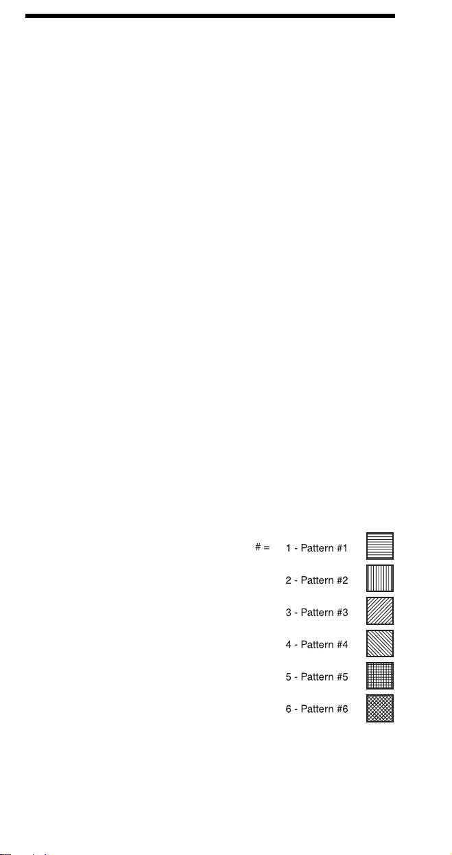
Pattern (Area Fill) ID (Pattern ID)
Specifies the level of shading or type of cross-hatch to select via Fill
Rectangular Area command.
? * c # G
If Shading fill is selected: OR, if Cross-Hatch Pattern
Decipoints
# = Number of decipoints (1/720 inch)
Dots
# = Number of dots (see Unit of Measure Command)
Decipoints
# = Number of decipoints (1/720 inch)
Dots
# = Number of dots (see Unit of Measure Command)
# = 0 - Rotate patterns with print direction
1 - Keep patterns fixed
fill is selected:
# = 1 thru 2 = 1-2% shade
3 thru 10 = 2-10% shade
11 thru 20 = 11-20% shade
21 thru 35 = 21-35% shade
36 thru 55 = 36-55% shade
56 thru 80 = 56-80% shade
81 thru 99 = 81-99% shade
100 = 100% shade
OR, if User-Defined Pattern
# = # of Pattern
Range = 0-32767
18
Page 21

Rectangular Area Fill Graphics (continued)
Fill Rectangular Area
Causes the defined rectangular area to be filled with the specified rule
pattern.
? * c # P
# = 0 - Solid area fill
1 - Solid white area fill
2 - Shading fill
3 - Cross-hatch pattern fill
4 - User-defined pattern
5 - Current pattern
User Defined Pattern
Downloads binary data that defines a user-defined pattern.
? * c # W
Pattern Control
Provides a means for manipulating user-defined (soft) patterns.
? * c # Q
[pattern data]
# = 0 - Number of pattern data bytes
# = 0 - Delete all patterns (temporary and permanent)
1 - Delete all temporary patterns
2 - Delete pattern (last pattern ID specified)
3 - Reserved
4 - Make pattern temporary (last pattern ID specified)
5 - Make pattern permanent (last pattern ID specified)
19
Page 22

Raster Graphics
Raster Graphics Resolution
Designates the graphics resolution for raster data operations.
? * t # R
# = 75 - 75 dots-per-inch
100 - 100 dots-per-inch
150 - 150 dots-per-inch
200 - 200 dots-per-inch
300 - 300 dots-per-inch
600 - 600 dots-per-inch
Raster Graphics Presentation Mode
Specifies the presentation of the raster image on the logical page.
? * r # F
# = 0 - image printed in the current print direction.
3 - image printed along the width of physical page.
Source Raster Height
Specifies the height in raster rows (pixels) of the raster picture area.
? * r # T
# = Height in raster rows
Source Raster Width
Specifies the width in pixels of the raster picture area.
? * r # S
# = width in pixels of the specified resolution
Destination Raster Width
Specifies the width in decipoints of the destination raster picture when
raster scaling.
? * t # H
# = Width in decipoints
Destination Raster Height
Specifies the height in decipoints of the destination raster picture when
raster scaling.
? * t # V
# = Height in decipoints
Scale Algorithm
Selects an algorithm for enhancing details when down-scaling color
images having light or dark backgrounds.
? * t # K
# = 0 Enhances color source image having a light background
# = 1 Enhances color source image having a dark background
20
Page 23

Raster Graphics (continued)
Start Raster Graphics
Specifies the left raster graphics margin.
? * r # A
# = 0 - sets left graphics margin at X-position 0.
1 - sets left graphics margin to the current column
(current X-position).
2 - Turn on scale mode (start raster at logical page left
boundary)
3 - Turn on scale mode (start raster at cursor position)
Y Offset
Moves the cursor vertically the specified number of raster lines from the
current line in the picture area.
? * b # Y
# = Number of raster lines of vertical movement.
Compression Method
Determines how the printer interprets (decodes) the binary data in the
Transfer Raster Data command.
? * b # M
# = 0 - Unencoded (default)
1 - Run-length encoding
2 - Tagged Image File Format (TIFF) revision 4.0
3 - Delta Row
5 - Adaptive Compression
Transfer Raster Data by Plane
Transfers a plane of raster data to the printer.
? * b # V
Transfer Raster Data by Row/Block
Transfers a row of raster graphics to the printer.
? * b # W
End Raster Graphics
Signifies the end of a raster graphic image transfer.
? * r B
? * r C
[data]
# = Number of bytes in the plane data
[binary data bytes]
# = Number of bytes in the raster row
-
All LaserJet printers III and newer
-
All LaserJet printers IIISi and newer (Preferred)
21
Page 24

Color
Simple Color
Creates a fixed-size palette whose color specifications cannot be
modified.
? * r # U
# = -3 - 3 planes, device CMY palette
1 - Single plane black and white palette
3 - 3 planes, device RGB palette
Configure Image Data (CID)
The CID command provides configuration information for palette creation
and raster data transmission in a single escape sequence by:
• designating the color space of the default palette,
• designating the size of the palette to be created,
• providing data for the resolution of color-space specific values into
device-specific values,
• designating the format of raster data, and
• designating how primary components are combined to yield the raster
presentation.
? * v # W
Color Component One
Specifies the first component of any new color entry of the palette.
? * v # A
Color Component Two
Specifies the second component of any new color entry of the palette.
? * v # B
Color Component Three
Specifies the third component of any new color entry of the palette.
? * v # C
Assign Color Index
Assigns the three current color components to the specified palette index
number.
? * v # I
[binary data]
# = Number of data bytes
# = First component
# = Second component
# = Third component
# = Index number
22
Page 25

Color (continued)
Push / Pop Palette
Pushes or pops the palette from the palette stack. The last item pushed is
the first item popped.
? * p # P
# = 0 - Push (save) palette
= 1 - Pop (restore) palette
Select Palette
Selects a new active palette by ID. The previously active palette is
unchanged.
? & p # S
# = Palette ID number
Palette Control ID
Specifies the ID to be used by the Palette Control command.
? & p # I
# = Palette ID number
Palette Control
Provides a mechanism for copying and deleting palettes.
? & p # C
# = 0 Delete all palettes except those in the stack (active
palette deleted)
= 1 Delete all palettes in the stack (active palette is not
affected)
= 2 Delete palette specified by Palette Control ID
= 6 Copy the active palette to the ID specified by the
Palette Control ID
Foreground Color
Sets the foreground color to the specified index of the curent palette.
? * v # S
# = Palette Index number
23
Page 26

Color (continued)
Render Algorithm
Selects an algorithm for rendering page marking entities on a given page.
? * t # J
# = 0 Continuous tone detail 300 lpi (device-best dither)
= 1 Snap to primaries
= 2 Snap black to white, color to black
= 3 Device-best dither
= 4 Error diffusion
= 5 Monochrome device-best dither
= 6 Monochrome error diffusion
= 7 Cluster ordered dither
= 8 Monochrome cluster ordered dither
= 9 User-defined dither
= 10 Monochrome user-defined dither
= 11 Ordered dither
= 12 Monochrome ordered dither
= 13 Noise ordered dither
= 14 Monochrome noise ordered dither
= 15 Continuous tone smooth 150 lpi
= 16 Monochrome continuous tone detail 300 lpi
= 17 Monochrome continuous tone smooth 150 lpi
= 18 Continuous tone basic 100 lpi
= 19 Monochrome continuous tone basic 100 lpi
Download Dither Matrix
Specifies a single dither matrix for all three primaries, or three matrices
(one for each primary) which may have different sizes and contents.
? * m # W
Color Lookup Tables
Enables and specifies color lookup tables.
? * l # W
Gamma Correction
Specifies the gamma correction to be applied equally for each primary.
? * t # I
Viewing Illuminant
Specifies the relative white point used in the determination of a viewing
illuminant condition.
? * i # W
[binary data]
# = Number of bytes in the data field
[binary data]
# = Number of bytes in the data field
# = Gamma number
[binary data]
# = Number of bytes in the data field
24
Page 27

Color (continued)
Monochrome Print Mode
Designates either the current rendering mode or a fast gray-scale
equivalent.
? & b # M
# = 0 Print in mixed render algorithm mode
# = 1 Print everything in gray equivalent
Status Readback
Set Status Readback Location Type
Sets the location type for an inquire entity status request.
? * s # T
# = 0 - Invalid Location
1 - Currently Selected
2 - All Locations
3 - Internal
4 - Download entity
5 - Cartridge
7 - SIMMs
Set Status Readback Location Unit
Sets the location unit for an inquire entity status request.
? * s # U
Location Type Location Unit 0 # = * Invalid location 1 = * Currently selected 2 = * All Locations 3 = 0 All internal 4 = 0 All downloaded
= 1 Temporary downloaded = 2 Permanent downloaded
5 = 0 All cartridge
= 1 Highest priority cartr idge
:: n Lowest priority cartridge
7 = 0 All SIMMs
= 1 Highest priority SIMM
:: n Lowest priority SIMM
25
Page 28

Status Readback (continued)
Inquire Status Readback Entity
Identifies the entity type and causes the printer to create a status
response.
? * s # I
# = 0 - Font
1 - Macro
2 - User-defined pattern
3 - Symbol set
4 - Font extended
Free Space
Returns the amount of total available user memory and the largest block
available.
? * s 1 M
Flush All Pages
Suspends accepting I/O data until all pages currently in printer are
printed.
? &r # F
# = 0 - Flush all complete pages
1 - Flush all pages
Echo
Echoes the value field value back to the host.
? * s # X
# = Echo value (-32767 to 32767)
26
Page 29

Picture Frame
Picture Frame Horizontal Size in Decipoints
Specifies the horizontal dimension of the area to be allocated for rendering
an HP-GL/2 plot.
? * c # X
# = Horizontal size in decipoints
Picture Frame Vertical Size in Decipoints
Specifies the vertical dimension of the area to be allocated for rendering
an HP-GL/2 plot.
? * c # Y
# = Vertical size in decipoints
Set Picture Frame Anchor Point
Sets the picture frame anchor point to current PCL cursor position.
? * c 0 T
HP-GL/2 Plot Horizontal Size
Specifies the horizontal size of the HP-GL/2 drawing being imported into
PCL.
? * c # K
# = Horizontal size in inches
HP-GL/2 Plot Vertical Size
Specifies the vertical size of the HP-GL/2 drawing being imported into
PCL.
? * c # L
# = Vertical size in inches
Enter HP-GL/2 Mode
Causes printer to begin interpreting the incoming data stream as HP-GL/2
commands instead of PCL commands.
? % # B
# = 0 - Use previous HP-GL/2 pen position
1 - Use current PCL cursor position for HP-GL/2 pen
position
2 - Use current PCL dot coordinate system and old
HP-GL/2 pen position
3 - Use current PCL dot coordinate system and the
current PCL cursor position
Enter PCL Mode
Causes printer to return to PCL mode from HP-GL/2 mode.
? % # A
# = 0 - Return cursor to previous PCL position
1 - Use current HP-GL/2 pen position for cursor position
27
Page 30

HP-GL/2
Configuration and Status Group
Default Values
Sets most programmable HP-GL/2 features to default conditions.
DF [;]
Initialize
Sets all programmable HP-GL/2 features to default conditions.
IN [;]
Input P1 and P2
Establishes new or default locations for the scaling points P1 and P2.
IP [XP1, YP1 [XP2, YP2]] [;]
XP1, YP1 = P1 location coordinates
X
, YP2 = P2 location coordinates
P2
Input Relative P1 and P2
Establishes P1 and P2 locations in relation to the PCL Picture Frame.
IR [XP1, Y
XP1, YP1 = P1 location as percentage of PCL Picture Frame
X
, YP2 = P2 location as percentage of PCL Picture Frame
P2
Input Window
Sets up a window (soft-clip limits).
IW [ XLL, YLL, XUR, YUR][;]
XLL = X coordinate (lower left)
Y
= Y coordinate (lower left)
LL
X
= X coordinate (upper right)
UR
Y
= Y coordinate (upper right)
UR
Rotate Coordinate System
Rotates the HP-GL/2 coordinate system.
RO [ angle ] [;]
angle = 0, 90, 180, or 270
Scale
Establishes a user-unit coordinate system.
SC [ X1, X2, Y1, Y2 [,type [,left, bottom ] ] ] [;]
SC X
, X
MIN
left, bottom = Positions isometric area within P1/P2 limits
, YP2]] [;]
P1 [XP2
type = 2 (point factor)
or
, Y
FACTOR
X1,Y1 = User-unit coordinates for P1
X2,Y2 = User-unit coordinates for P2
type = 0 (Anisotropic) or 1 (isotropic)
MIN
, Y
FACTOR
, type [;]
28
Page 31

HP-GL/2
Vector Group
Arc Absolute
Draws an arc using absolute coordinates.
AA X
CTR,YCTR
Arc Relative
Draws an arc using relative coordinates.
AR X
INCR,YINCR
Absolute Arc Three Point
Draws an arc from the current pen location through two absolute points.
AT X
INTRM,YINTRM,XEND,YEND
Bezier Absolute
Draws a Bezier curve using absolute coordinates.
BZ X1, Y1, X2, Y2, X3, Y3 [;]
Bezier Relative
Draws a Bezier curve using relative coordinates.
BR X1, Y1, X2, Y2, X3, Y3 [;]
Circle
Draws a circle with a specified radius.
CI radius [,chord angle] [;]
Plot Absolute
Enables movement to absolute coordinate locations (with respect to the
origin [ 0,0]).
PA [ X, Y... [,X,Y ] ] [;]
Pen Down
Lowers the logical “pen” to the page.
PD [ X, Y... [,X,Y ] ] [;]
Polyline Encoded
Encodes common HP-GL/2 commands to increase throughput.
PE [flag] [val] | coord pair... [flag] [val] | coord pair ;
or
PE;
,sweep angle [,chord angle] [;]
,sweep angle[,chord angle] [;]
[,chord angle] [;]
Flag = < – pen up
> – fractional data
= – absolute
7 – 7-bit data7
: – Select pen
29
Page 32

HP-GL-2
Vector Group (continued)
Plot Relative
Enables movement relative to the current pen location.
PR [ X,Y... [,X,Y ] ] [;]
Pen Up
Lifts the logical “pen” from the page.
PU [ X,Y...[ ,X,Y ] ] [;]
Relative Arc Three Point
Draws an arc from the current pen location through two relative points.
RT X
Y
INCR END
INCR INTRM
[,chord angle] [;]
Y
,
INCR INTRM
X
,
INCR END
,
Polygon Group
Edge Rectangle Absolute
Outlines a rectangle defined with absolute coordinates.
EA X,Y [;]
X,Y = Coordinates of opposite corner of rectangle.
Edge Rectangle Relative
Outlines a rectangle defined with relative coordinates.
ER X,Y [;]
X,Y = Coordinates of opposite corner of rectangle.
Edge Wedge
Defines and outlines a wedge-shaped polygon.
EW radius,start angle,sweep angle[,chord angle] [;]
Edge Polygon
Outlines the polygon resident in the polygon buffer.
EP [;]
Fill Polygon
Fills the polygon specified in the polygon buffer with the current fill type.
FP [fill method][;]
fill method = 0 - Odd/Even fill
1 - Non-zero winding fill
30
Page 33

HP-GL/2
Polygon Group (continued)
Polygon Mode
Allows creation of user-defined polygons in the polygon buffer.
PM polygon definition [;]
polygon definition = 0 (Clears polygon buffer and enters
polygon mode)
1 (Closes current polygon or subpolygon
and remains in polygon mode)
2 (Closes current polygon or subpolygon
and exits polygon mode)
Fill Rectangle Absolute
Fills a rectangle specified with absolute coordinates.
RA X,Y [;]
X,Y = Coordinates of opposite corner of rectangle.
Fill Rectangle Relative
Fills a rectangle specified with relative coordinates.
RR X,Y [;]
X,Y = Coordinates of opposite corner of rectangle.
Fill Wedge
Defines and fills a wedge-shaped polygon.
WG radius,start angle,sweep angle[,chord angle] [;]
Line and Fill Attributes Group
Anchor Corner
Specifies the starting point for fill patterns.
AC [ X,Y] [;]
Fill Type
Selects the pattern to use when filling polygons.
FT [ fill type[,option1[,option2 ] ] ] [;]
Fill Type = description option1 option2
1 and 2 = Solid black ignored ignored
3 = Hatched line spacing angle
4 = Cross-hatched line spacing angle 10 = Shading % shading ignored 11 = User-defined raster-fill index ignored 21 = PCL Patterns pattern type ignored 22 = PCL User-
defined
pattern ID ignored
31
Page 34

HP-GL/2
Line and Fill Attributes Group (continued)
Line Attributes
Specifies how line ends and joins are shaped.
LA [ kind, value...[,kind, value ] ] [;]
Attribute = Kind, Value - Description
Line Ends = 1, 1 - Butt (default)
= 2 - Square = 3 - Triangular = 4 - Round
Line Joins = 2, 1 - Mitered (default)
= 2 - Mitered/beveled = 3 - Triangular = 4 - Round = 5 - Beveled = 6 - No join applied
Miter Limit = 3, 1 to 32,767 - Max. length of miter
(miter length/pen width ratio)
(default = 5)
Line Type
Selects the line pattern to use for drawing lines.
LT [ line type[,pattern length[,mode ] ] ] [;]
mode = 0 (relative mode – interprets pattern length as
percentage of diagonal distance between P1 and P2.
= 1 (absolute – interprets the pattern length parameter
in mm.
Pen Width
Specifies a new pen width.
PW [ width [,pen ] ] [;]
Raster Fill Definition
Defines a pattern for use as area fill.
RF [ index[,width, height, pen number [,...pen
number ] ] ][;]
Symbol Mode
Draws a symbol (character) at each coordinate location.
SM [ character][;]
Select Pen
Selects a pen for plotting.
SP [ pen] [;]
pen = 0 (white)
1 (black)
Default is no pen.
32
Page 35

HP-GL/2
Line and Fill Attributes Group (continued)
Screened Vectors
Selects type of area fill for vectors (lines, hatch lines, arcs, circles, edges
of polygons, rectangles, and wedges).
SV [ screen type [,option1[,option2]]][;]
screen type = description option 1 option 2
0 = No screening ignored ignored
1 = Shaded fill % shading ignored
2 = User defined index no. pen flag 21 = PCL Patterns patter n type ignored 22 = PCL User-defined
Patterns
Transparency Mode
Defines how the white areas of the source graphics image affect the
destination graphics image.
TR [ n][;]
n = 1 (Transparency mode=on [ default])
0 (Transparency mode=off)
User Defined Line Type
Defines a line pattern.
UL [ index[,gap1, . . . ,gapn ] ][;]
index = Line pattern number. [1–8]
gap = Percentage of pattern length for that portion (first
gap is a pen-down move).
Pen Width Unit Selection
Specifies whether pen width is defined in millimeters or as a
percentage of P1/P2 distance.
WU [ type] [;]
type = 0 (millimeters)
= 1 (percentage of P1/P2 distance)
pattern ID ignored
33
Page 36

HP-GL/2
Character Group
Alternate Font Definition
Specifies an alternate font for labeling.
AD [ kind, value...[,kind, value ] ] [;]
Kind Attribute Value
1 Symbol Set * 2 Font spacing 0 (fixed); 1 (prop.) 3 Pitch characters per inch 4 Height font point size 5 Posture 0 (upright); 1 (italic) 6 Stroke Weight 0 (medium); 3 (bold)* 7 Typeface *
* See tables in Appendix C of the
Character Fill Mode
Specifies how outline fonts will be rendered.
CF [ fill mode [,edge pen*]] [;]
fill mode = 0 (solid fill and edged)
1 (edging with specified pen [or current pen if edge
pen parameter not specified]; characters filled if
can't be edged)
2 (fill with current fill type; characters are not
edged)
3 (fill with current fill type; edge characters with
the specified pen or current pen if edge pen
parameter is not specified)
edge pen = pen number to be used for edging.
* Using 0 means edge in pen 0.
Character Plot
Moves the pen the specified number of character “cells” from the current
pen location.
CP [ spaces, lines] [;]
Absolute Label Direction
Specifies the slope of labels independent of P1 and P2 locations.
DI [ run,rise ][;]
run = the X-component of the label direction or
the angle
rise = the Y-component of the label direction or
angle
PCL 5 Comparison Guide
COSINE
of
SINE
of the
.
34
Page 37

HP-GL/2
Character Group (continued)
Relative Label Direction
Specifies the slope of labels relative to P1 and P2 locations.
DR [ run,rise] [;]
run = percentage of distance between P1X and P2
rise = percentage of distance between P1Y and P2Y.
Define Label Terminator
Defines the character that “turns off” labeling.
DT [ lblterm [,mode ] ];
lblterm = character to be used as terminator
mode = 0 (print label terminator)
1 (do not print terminator)
Define Variable Text Path
Specifies the label path as right, left, up, or down.
DV [ path [,line ] ] [;]
path = 0 (0 degrees – right)
1 (-90 degrees – down)
2 (-180 degrees – left)
3 (-270 degrees – up)
line = 0 (-90 degrees – normal line feed)
1 (+90 degrees – reverse line feed)
Extra Space
Increases or reduces space between characters and lines of text.
ES [ width [,height ] ] [;]
width = number (or fractional number) of character spaces
height = number (or fractional number) of lines
Select Primary Font ID
Selects as primary a font previously assigned a PCL font ID number.
FI font ID [;]
font ID = Font ID number assigned in PCL mode.
Select Secondary Font ID
Selects as secondary a font previously assigned a font ID number.
FN font ID [;]
font ID = Font ID number assigned in PCL mode.
X
35
Page 38

HP-GL/2
Character Group (continued)
Label
Prints text using the currently selected font.
LB text . . . text lblterm [;]
text . . . text = Any characters.
lblterm = Label terminator (default Ext or defined with
DT command).
Label Origin
Specifies the positioning of the characters within a label.
LO [ position] [;]
position = Number indicating label position relative to
current cursor position (see command description
PCL5 Technical Reference Manual
in
Label Mode
Determines how LB (Label) and SM (Symbol Mode) interpret characters.
Most often used for printing a 2-byte character set such as Kanji.
LM [mode,[row number]:]
mode = determines the interpretation mode as follows:
0 Interprets each byte as a character (8-bit mode).
1 Interprets the next two bytes as a character (16-bit mode).
2 Same logic as mode 0 except that vertical substitutes are
used if found in a VT segment of the current font.
3 Same logic as mode 1 except that vertical substitutes are
used if found in a VT segment of the current font.
row number = indicates the first byte while the LB or SM
instruction supplys the second byte. Used only in mode 0 when a
16-bit character set is selected.
Select Alternate Font
Selects the font designated by AD.
SA [;]
Scalable or Bitmap Fonts
Specifies the type of fonts to be used for labels.
SB [ n] [;]
n = 0 (Scalable fonts [default])
= 1 (Bitmap and scalable fonts)
).
36
Page 39

HP-GL/2
Character Group (continued)
Standard Font Definition
Specifies the standard font for printing labels.
SD [ kind, value...[,kind, value ] ] [;]
Kind Attribute Value
1 Symbol Set * 2 Font spacing 0 (fixed); 1 (prop.) 3 Pitch characters per inch 4 Height font point size 5 Posture 0 (upright); 1 (italic) 6 Stroke Weight 0 (medium); 3 (bold)* 7 Typeface *
* See tables in Appendix C of the
Absolute Character Size
Specifies an absolute character size (in centimeters).
SI [ width, height] [;]
Character Slant
Specifies the slant at which labels are printed.
SL [ tangent of angle] [;]
tangent of angle = Tangent of slant angle (measured from
vertical)
Relative Character Size
Specifies character size as a percentage of the P1/P2 distance.
SR [ width, height] [;]
Select Standard Font
Selects the font designated by SD for printing labels.
SS [;]
Transparent Data
Specifies whether control characters perform their function or are printed
as characters.
TD [ mode] [;]
mode = 0 (Normal)
1 (Transparent)
PCL 5 Comparison Guide
.
37
Page 40

HP-GL/2
Technical Drawing Extensions Group
Merge Control
Specifies the logical operation (ROP3) to be performed.
MC[mode[,opcode]];
mode = 0 - opcode value ignored (ROP set to 252 [default])
1 - opcode value used as ROP value
opcode = logical operation (ROP3 value)
Pixel Placement
Specifies either grid intersection or grid-centered pixel placement.
PP[mode];
mode = 0 - grid intersection (default)
1 - grid centered
Programming Hints
End-Of-Line Wrap
Defines action that occurs when text reaches right margin: perform a
carriage return or do not perform carriage return (truncate data).
? & s # C
# = 0 - Enables End-Of-Line Wrap
1 - Disables End-Of-Line Wrap
Display Functions
Causes all escape sequences and control codes to be printed instead of
executed.
? Y – Enables Display Functions
? Z – Disables Display Functions
38
Page 41

PJL
Kernel
Universal Exit Language
Terminates operation of current language and returns control to PJL.
Every job should begin and end with this command.
<ESC> % –12345X
Enter Language
Causes PJL to enable the specified language.
PCL
@PJL ENTER LANGUAGE
POSTSCRIPT
others
[CR] <LF>=
Comment
Allows one line of comment text to be entered in PJL.
@PJL COMMENT
comment text . . .
[CR] <LF>
Job Separation
Job
Indicates the start of a print job, resets the page count and allows naming
of the job; supports non-printing mode. Also, used for providing the password for PJL security.
@PJL JOB
[NAME= ]
[START= ]
[END= ]
[PASSWORD = ]
“
job name
first page
last page
”
[CR] <LF>
number
End-Of-Job
Tells printer the job has completed, resets the page count.
@PJL EOJ [NAME =
“job name”
] [<CR>] <LF>
39
Page 42

PJL
Environment
Initialize
Resets current and default PJL variables to factory default values.
@PJL INITIALIZE [<CR>]<LF>
Reset
Resets current PJL variables to default values.
@PJL RESET [<CR>]<LF>
Default
Sets default value for environment variables.
@PJL DEFAULT [LPARM :
~
variable = value [<CR>] <LF>
Set
Sets the environment variable for the duration of a PJL job.
@PJL SET [LPARM :
~
variable = value [<CR>] <LF>
personality
personality
| IPARM :
| IPARM :
port
port
]
]
Status Readback
Inquire
Requests the current value for an environment variable.
@PJL INQUIRE [LPARM :
~
variable [<CR>] <LF>
Response
@PJL INQUIRE [LPARM :
~
variable<CR><LF>
value <CR><LF>
<FF>
Dinquire
Requests the default value for a specified environment variable.
@PJL DINQUIRE [LPARM :
~
variable [<CR>] <LF>
Response
@PJL DINQUIRE [LPARM :
~
variable<CR> <LF>
value <CR><LF>
<FF>
~ - Indicates that the following data is part of the preceding line.
personality
personality
personality
personality
| IPARM :
| IPARM :
| IPARM :
| IPARM :
port
port
port
port
]
]
]
]
40
Page 43

PJL
Status Readback (continued)
Info
Request a specified category of printer information.
@PJL INFO
Response
@PJL INFO
[1 or more lines of printable characters or <WS> followed by]
<CR><LF>
<FF>]
Echo
Returns the “words” portion of the command to the host computer.
@PJL ECHO [<Words>] [<CR>] <LF>
Response
@PJL ECHO [<Words>] <CR><LF>
<FF>
Ustatus
Allows printer to send unsolicited status messages.
@PJL USTATUS
Response
@PJL USTATUS
[1 or more lines of printable characters or <WS> followed by]
<CR><LF>
<FF>
Ustatusoff
Turns off all unsolicited status.
@PJL USTATUSOFF [<CR>]<LF>
category
category
[<CR>]<LF>
<CR><LF>
variable = value
variable
[<CR>]<LF>
<CR><LF>
41
Page 44

PJL
Device Attendance
Operator Message
Displays specified message on control panel and takes printer offline.
@PJL OPMSG DISPLAY =
Ready Message
Specifies a message that replaces the READY message on the printer
control panel. Doesn't affect on-line state.
@PJL RDYMSG DISPLAY =
Status Message
Displays specified message on printer control panel and takes printer
offline. Returns name of the key that is pressed by operator to put the
printer back online.
@PJL STMSG DISPLAY =
Response
@PJL STMSG DISPLAY =
key <CR><LF>
<FF>
“message”
“message”
“message”
“message”
[<CR>]<LF>
[<CR>]<LF>
[<CR>]<LF>
<CR><LF>
File System
FSDELETE
Deletes printer disk files.
@PJL FSDELETE NAME =
FSDOWNLOAD
Downloads a file to the printer disk file system.
@PJL FSDOWNLOAD FORMAT:BINARY [SIZE=int] [<CR>]<LF>
FSINIT
Initializes the printer disk file system.
@PJL FSINIT VOLUME =
FSMKDIR
Creates the specified directory on the printer disk file system.
@PJL FSMKDIR NAME =
“pathname”
“pathname”
“pathname”
[<CR>]<LF>
[<CR>]<LF>
[<CR>]<LF>
42
Page 45

PCL C O M M A N D S U M M A R Y
Job Control
Universal Exit Language
Configuration (I/O)
Printer Reset
Number of Copies
Simplex/Duplex
Long-edge Offset Registration
Short-edge Offset Registration
Duplex Page Side Selection
Job Separation
Output Bin (Media Bin)
Unit-of-Measure
Page Control
Page Size
Paper (Media) Source
Page Length (Obsolete)
Orientation
Print Direction
Character Text Path Direction
Text Parsing Method
Left Margin
Right Margin
Clear Horizontal Margins
Top Margin
Text Length
Perforation Skip
Horizontal Motion Index
Vertical Motion Index
Line Spacing
% – 1 2 3 4 5 X
?
b # W[data]
? &
?E
? & l
? & l
? & l
? & l
? &
? & l
? & l
# X
# S
# U
# Z
a # G
1 T
# G
? & u # D
? & l
? & l
# A
# H
? & l # P
? & l
# O
? & a # P
c # T
? &
? & t # P
a # L
? &
? &
a # M
? 9
? & l # E
? & l
? &
l
? & k
? & l
? & l
# F
# L
# H
# C
# D
43
Page 46

Cursor Positioning
Horizontal Cursor Positioning
Columns
Decipoints
Units-of-Measure
Control Codes
Carriage Return
Space
Backspace
Horizontal Tab
Vertical Cursor Positioning
Rows
Decipoints
Units-of-Measure
Half Line-Feed
Control Codes
Line-Feed
Form-Feed
Line Termination
Push/Pop Cursor Position
Font Selection
Symbol Set
Spacing
Pitch
Height
Style
Stroke Weight
Typeface
Font Selection by ID #
Select Default Font
Transparent Print Data
Underline - Enable
†
†
†
†
†
†
†
- Disable
†
†
&
a # C
?
? & a # H
*
p # X
?
CR
SP
BS
HT
&
a # R
?
&
a # V
?
*
p # Y
?
=
?
LF
FF
&
k # G
?
&
f # S
?
(
ID
?
(
s # P
?
(
s # H
?
(
s # V
?
(
s # S
?
(
s # B
?
(
s # T
?
(
# X
?
(
3 @
?
&
p # X
?
&
d # D
?
&
d @
?
[transparent data ]
Font Management
*
c # D
Font ID # (specify)
Font Control
Alphanumeric ID
User-Defined Symbol Set
Symbol Set ID Code
Define Symbol Set
Symbol Set Management
†
Command shown for primary only, reverse parenthesis for secondary command.
?
*
c # F
?
? & n # W
*
c # R
?
( f # W
?
?
44
[symbol set definition data]
*
c # S
[operation][string]
Page 47

Font Descriptor /Data
Character Code
Character Descriptor/Data
Macro ID # (specify)
Macro Control
Source Transparency Mode
Pattern Transparency Mode
Pattern (Area Fill) ID
Select Current Pattern
User-Defined Pattern
Set Pattern Reference Point
Pattern Control
Logical Operation
Pixel Placement
Rectangular Area Fill Graphics
Horizontal Rectangle Size
Decipoints
Units-of-Measure
Vertical Rectangle Size
Decipoints
Units-of-Measure
Pattern ID (Area Fill ID)
Fill Rectangular Area
Font Creation
s # W
?)
c # E
? *
s # W
? (
Macros
f # Y
? &
? & f # X
Print Model
v # N
? *
v # O
? *
c # G
? *
v # T
? *
? * c # W
* p # R
?
? * c
? * l
? * l
? *
?
? *
# Q
# O
# R
c # H
* c # A
c # V
? * c # B
c # G
? *
* c # P
?
[descriptor data ]
[binary data ]
[pattern data]
Raster Resolution
Presentation
Source Raster Height
Source Raster Width
Destination Raster Height
Destination Raster Width
Scale Algorithm
Start Raster Graphics
Y Offset
Set Compression Mode
Transfer Raster Data
End Raster Graphics
Raster Graphics
t # R
? *
r # F
? *
r # T
? *
* r # S
?
t # V
? *
t # H
? *
t # K
? *
r # A
? *
? * b # Y
b # M
? *
b # W
? *
? * r B
? * r C
45
[raster data ]
Page 48

Simple Color
Configure Image Data
Color Component One
Color Component Two
Color Component Three
Assign Color Index
Push/Pop Palette
Select Palette
Palette Control ID
Palette Control
Foreground Color
Render Algorithm
Download Dither Matrix
Color Lookup Tables
Gamma Correction
Viewing Illuminant
Monochrome Print Mode
Set Location Type
Set Location Unit
Inquire Entity
Free Space
Flush All Pages
Echo
Color
*
r # U
?
* v # W
?
*
v # A
?
*
v # B
?
*
v # C
?
*
v # I
?
* p # P
?
? &p # S
&p # I
?
&p # C
?
? * v # S
*
t # J
?
* m # W
?
l # W
? *
* t # I
?
? * i # W
&b # M
?
Status Readback
* s # T
?
* s # U
?
? * s # I
* s # M
?
&r # F
?
* s # X
?
[data]
[data]
[data]
[data]
Picture Frame
Picture Frame Horizontal Size
Picture Frame Vertical Size
Set Picture Frame Anchor Point
HP-GL/2 Plot Horizontal Size
HP-GL/2 Plot Vertical Size
Enter HP-GL/2 Mode
Enter PCL Mode
* c # X
?
* c # Y
?
* c 0 T
?
* c # K
?
*
?
% # B
?
% # A
?
46
c # L
Page 49

Config./Status Group (HP-GL/2)
Default Values DF[;]
Initialize IN[;]
Input P1 and P2 IP[X
Input Relative P1 and P2 IR[X
Input Window IW[ X
, YP1[,XP2,YP2 ] ] [;]
P1
, YP1[,XP2,YP2] ] [;]
P1
LL,YLL,XUR,YUR
] [;]
Rotate Coordinate System RO[ angle] [;]
Scale SC[ X
1,X2,Y1,Y2
[,type[,left
bottom ]]] [;] or
SC X
MIN,
X
FCTR
,Y
,Y
FCTR
,
MIN
type[;]
Vector Group (HP-GL/2)
Arc Absolute AA X
CTR,YCTR
[,chord angle] [;]
Arc Relative AR X
INCR,YINCR
[,chord angle] [;]
Absolute Arc Three Point AT X
INTRM
[,chord angle] [;]
Bezier Absolute BZx1_control_pt,y1_control_pt
x2_control_pt,y2_control_pt
x3_control_pt,y3_control_pt...
[x1_control_pt,y1_control_pt
x2_control_pt,y2_control_pt
x3_control_pt,y3_control_pt];
Bezier Relative BRx1_control_pt_increments,
y1_control_pt_increments,
x2_control_pt_increments,
y2_control_pt_increments,
x3_control_pt_increments,
y3_control_pt_increments...
[x1_control_pt_increments,
y1_control_pt_increments,
x2_control_pt_increments,
y2_control_pt_increments,
x3_control_pt_increments,
y3_control_pt_increments];
Circle CI radius[,chord angle] [;]
Plot Absolute PA[ X,Y...[,X,Y] [;]
Pen Down PD[ X, Y...[,X,Y] [;]
,sweep angle
,sweep angle
,Y
,X
INTRM
END
, Y
END
,
Polyline Encoded PE[ flag][val] | [coord pair]...
[flag][val] | [coord pair ];
PE;
or
Plot Relative PR[ X,Y...[,X,Y]] [;]
Pen Up PU[ X,Y...[,X,Y]] [;]
Relative Arc Three Point RT X
INCR INTRM,YINCR INTRM
X
INCR END
[,chord angle] [;]
, Y
INCR END
47
,
Page 50

Polygon Group (HP-GL/2)
Edge Rectangle Absolute EA X,Y[;]
Edge Polygon EP[;]
Edge Rectangle Relative ER X,Y[;]
Edge Wedge EW radius, start angle, sweep
angle [,chord angle] [;]
Fill Polygon FP fill method[;]
Polygon Mode PM polygon definition[;]
Fill Rectangle Absolute RA X,Y[;]
Fill Rectangle Relative RR X,Y[;]
Fill Wedge WG radius, start angle, sweep
angle [,chord angle] [;]
Line and Fill Attributes Group (HP-GL/2)
Anchor Corner AC [ X,Y] [;]
Fill Type FT[ fill type[,option1[ option2 ] ] ] [;]
Line Attributes LA [ kind, value...[,kind,value] ] [;]
Line Type LT [ line type[,pattern length
Pen Width PW[ width[,pen ] ] [;]
Raster Fill Definition RF [index[,width,height,pen
Symbol Mode SM[ character] [;]
Select Pen SP[ pen] [;]
Screened Vectors SV[ screen type[,option1
Transparency Mode TR[ n] [;]
User Defined Line Type UL[ index[,gap1 . . . gapn] [;]
Pen Width Unit Selection WU[ type] [;]
[,mode ] ] ] [;]
number][, . . . pen number] ] [;]
[,option2 ] ] ] [;]
Character Group (HP-GL/2)
Alternate Font Definition AD [ kind,value...[,kind,value]] [;]
Character Fill Mode CF[ fill mode[,edge pen ] ] [;]
Character Plot CP [ spaces,lines] [;]
Absolute Direction DI[ run,rise] [;]
Relative Position DR[ run, rise] [;]
Define Label Terminator DT[ lblterm[,mode ] ] ;
Define Variable Text Path DV[ path[,line ] ] [;]
Extra Space ES[ width[,height ] ] [;]
Select Primary Font FI font ID[;]
Select Secondary Font FN font ID[;]
Label LB text . . . text lblterm[;]
Label Origin LO[ position] [;]
Label Mode LM[mode,[row number];]
Select Alternate Font SA[;]
Scalable or Bitmap Fonts SB[ n] [;]
Standard Font Definition SD[ kind,value...[,kind,value ] ] [;]
Absolute Character Size SI[ width,height] [;]
Character Slant SL[ tangent of angle] [;]
Relative Character Size SR[ width,height] [;]
Select Standard Font SS[;]
Transparent Data TD[ mode] [;]
48
Page 51

Technical Drawing Extensions Group (HP-GL/2)
Merge Control MC[mode[,opcode]];
Pixel Placement PP[mode];
Programming Hints
& s # C
End-Of-Line Wrap
Display Functions - Enable
- Disable
?
? Y
Z
?
49
Page 52

Notes
50
Page 53

Page 54
Printed on
Recycled Paper
Copyright© 1999
Hewlett-Packard Co.
Printed in USA
 Loading...