

Page 1

HP Designjet 3D
Service Guide
HP Designjet Color 3D
Page 2

Legal Notice
The information contained herein is subject
to change without notice.
The only warranties for HP Products and
services are set forth in the express warranty
statement accompanying such products and
services. Nothing herein should be
construed as constituting an additional
warranty. HP shall not be liable for technical
or editorial errors or omissions contained
herein.
© 2012 Hewlett-Packard Development
Company, L.P.
Rev. C
Microsoft
®
and Windows
®
are U.S. registered
trademarks of Microsoft Corporation.
.
Conforms to ANSI/UL std. 60950-1-2003
Certified to CAN/CSA C22.2 no. 60950-1-03
HP Designjet 3D and HP Designjet Color 3D
conform with the following standards, in accordance with the
EU Machinery, Low Voltage and Electromagnetic
Compatibility Directives: EU 98/37/EEC, EU 73/23/EEC
amended by 93/68/EEC, EU 89/336/EEC
Page 3

Page 4

-3
Page 5

Table of Contents
Introduction .....................................................................................................1
How to use this guide ......................................................................................................1
Safety............................................................................................................................ 2
Overview .........................................................................................................3
What happens when... ...........................................................................................3
Powering up: .........................................................................................................3
Powering Down ..................................................................................................... 4
Loading Material.................................................................................................... 4
Building a Part .......................................................................................................4
Electronics Overview .............................................................................................. 6
Single Board Computer...........................................................................................7
Controller Board .................................................................................................... 8
Overview .............................................................................................................. 8
Voltage Generation ................................................................................................8
Dual Port Memory Interface .....................................................................................8
X, Y, Z Axis Control................................................................................................8
Material Motor Control ...........................................................................................8
Temperature Control ...............................................................................................8
Liquefier Temperature Control .................................................................................. 9
Actuators, Switches & Optical Sensors ...................................................................... 9
Safety Devices .....................................................................................................10
Controller Board Layout ........................................................................................ 10
Reset Button ......................................................................................................... 11
Dip Switches........................................................................................................ 11
SW2 ..................................................................................................................12
SW5 ..................................................................................................................12
SW6 ..................................................................................................................12
Memory .............................................................................................................. 12
LEDs ...................................................................................................................12
Power Distribution Board (PDB) ..............................................................................14
Chamber Temperature Control ............................................................................... 15
Test Points and LED’s ............................................................................................ 16
I/O Card ............................................................................................................ 18
Head Board ........................................................................................................19
Printer overview ...................................................................................................20
Page 6

Setup ............................................................................................................25
Installing software ......................................................................................................... 25
Installing HP Designjet 3D Software Solution:......................................................25
Installing firmware to the workstation: ................................................................25
Networking the printer................................................................................................... 25
Connecting through a network: ......................................................................... 25
Connecting directly to a workstation: ................................................................. 25
Establishing network communication with the printer ......................................................... 26
Establishing communication on a dynamic network: ............................................26
Establishing communication on a static network: .................................................27
Setting the static network in Windows XP: ..........................................................27
Setting the static network in Windows Vista: .......................................................27
Setting the static network in Windows 7:............................................................ 28
Setting the static network on printer: ..................................................................28
Establish communication: .................................................................................29
Installing Firmware on printer .........................................................................................30
Adding the second HP Designjet 3D Material Bay.............................................................31
Installing the HP Designjet 3D Material Bay: .......................................................31
Operation ......................................................................................................37
Display panel and keypad .............................................................................................37
System firmware overview.............................................................................................. 38
HP Designjet 3D Software Solution overview ....................................................................39
Processing your STL file for printing .................................................................................40
Opening your STL file with HP Designjet 3D Software Solution:.............................40
Selecting layer resolution:.................................................................................40
Selecting model interior fill style: .......................................................................40
Selecting support style:.....................................................................................41
Selecting the scale of your STL file: .................................................................... 41
Selecting the orientation of your STL file: ............................................................ 41
Adding your STL file to the pack:....................................................................... 42
Printing your STL file: .......................................................................................42
Building a part .............................................................................................................43
Starting a build from a remote location: ............................................................. 43
Starting a build from the display panel:.............................................................. 43
The display panel during build ....................................................................................... 44
Chamber Lights............................................................................................................. 44
Pausing a build............................................................................................................. 45
Resuming after pause ....................................................................................................45
Canceling a build ......................................................................................................... 45
Page 7

Removing a completed part............................................................................................ 46
Remove a part from the modeling base: .............................................................46
Removing support material .............................................................................................46
Emptying the purge bucket .............................................................................................47
Replacing material for single material bay .......................................................................47
Replacing material for dual material bays ........................................................................48
Material bay LEDs.........................................................................................................49
Replacing material spools ..............................................................................................50
Removing a spool of material from the carrier:....................................................50
Storing material spools .................................................................................................. 50
Auto power down .........................................................................................................52
Cancelling auto power down:........................................................................... 52
Powering off.................................................................................................................53
Resuming operations from Standby mode ........................................................................53
Updating printer firmware:............................................................................................. 53
Installing the firmware:..................................................................................... 53
Software ........................................................................................................55
Software Architecture .................................................................................................... 55
Operating System ......................................................................................................... 55
Display Driver ..............................................................................................................55
Comm Server ...............................................................................................................56
System Manager...........................................................................................................56
Move Compiler............................................................................................................. 56
Feeder......................................................................................................................... 56
Event/Command Monitor...............................................................................................56
HP Designjet 3D Software Solution Help ..........................................................................57
HP Designjet 3D Software Solution overview ...........................................................57
Conventional help file ...........................................................................................57
Dynamic help ...................................................................................................... 57
Maintenance ..................................................................................................59
Startup kit tools............................................................................................................. 59
Preventive Maintenance ................................................................................................. 59
Daily ..................................................................................................................59
Empty the purge bucket....................................................................................59
Inspect the tip wipe assembly............................................................................59
Inspect the tip shields .......................................................................................59
Remove debris buildup.....................................................................................59
Vacuum build chamber ....................................................................................59
Clean door.....................................................................................................59
Page 8

500 Hour maintenance..................................................................................................60
Tip wipe assembly................................................................................................ 60
Tip shield replacement .......................................................................................... 62
Remove debris from the Filament Present switch .......................................................64
2000 Hour maintenance................................................................................................66
Tip replacement and calibration.............................................................................66
Removing tips: ................................................................................................ 66
Installing tips:..................................................................................................68
Tip calibration: ...............................................................................................71
Chamber light bar replacement.............................................................................. 73
Troubleshooting .............................................................................................75
User Troubleshooting.....................................................................................................75
Fault determination codes......................................................................................77
Cycling power ..................................................................................................... 78
Diagnosing loss of extrusion ..................................................................................78
Clogged tip .........................................................................................................79
Material Jam........................................................................................................80
Recovering from loss of extrusion ........................................................................... 82
Service Troubleshooting ................................................................................................. 86
1.0 How to use this Guide ....................................................................................86
2.0 Special Notes ................................................................................................87
3.0 Code Errors ................................................................................................... 88
Major Codes with Minor Codes .............................................................................90
4.0 Non-Code Errors .......................................................................................... 107
What happens during Power Up / Boot................................................................ 119
5.0 Connector Pinouts and Signals....................................................................... 129
Umbilical cable diagram.....................................................................................129
Umbilical cable pinouts.......................................................................................129
Upper harness ...................................................................................................131
Upper harness pinouts ........................................................................................132
Lower harness....................................................................................................133
Lower harness pinouts.........................................................................................133
Part Quality Troubleshooting ........................................................................................135
Embedded support strands in model ..................................................................... 135
Brown streaks (burn marks).................................................................................. 136
Loss of Extrusion (LOE) ........................................................................................137
Model embedded in to support ............................................................................ 139
Moisture in material............................................................................................ 140
Open seams ......................................................................................................141
Page 9

Part curling........................................................................................................142
Part fell over ...................................................................................................... 143
Part shifting ....................................................................................................... 144
Rough surface quality .........................................................................................146
Rough quality all over .........................................................................................147
Model strands on parts .......................................................................................148
Witness marks ...................................................................................................149
Wavy surface .................................................................................................... 150
Wavy parts ....................................................................................................... 151
Under fill........................................................................................................... 152
Material sagging on curved parts.........................................................................153
Fused layers ...................................................................................................... 154
Z layers inconsistent ...........................................................................................155
Removal and Installation ..............................................................................157
Maintenance Preparation.............................................................................................159
Tools needed for repair not order-able as a service part.......................................... 160
Tools needed for repair that are order-able as a service part ...................................160
Pre-Maintenance Procedures ................................................................................160
Exterior Components ................................................................................................... 161
Top Panel..........................................................................................................161
Removing the top panel ................................................................................. 161
Installing the top panel...................................................................................162
Side Panels........................................................................................................162
Removing the side panels ............................................................................... 162
Removing the right side panel: ........................................................................164
Installing the side panels ................................................................................164
Display Panel.....................................................................................................165
Removing the display panel............................................................................165
Installing the display panel .............................................................................166
Front Panel ........................................................................................................166
Removing the front panel................................................................................166
Installing the front panel .................................................................................168
Door Solenoid ...................................................................................................168
Removing the door solenoid ........................................................................... 168
Installing the door solenoid............................................................................. 169
Door Sensor ...................................................................................................... 169
Removing the door sensor ..............................................................................169
Installing the door sensor................................................................................ 170
Electronics Bay Components.........................................................................................171
Page 10

Lower Electronics Bay Cover ................................................................................171
Opening the electronics bay ...........................................................................171
Closing the electronics bay.............................................................................172
Upper Electronics Bay Cover ...............................................................................173
Removing the upper electronics bay cover ........................................................173
Installing the upper electronics bay cover .........................................................174
Removing the Electronics Bay............................................................................... 175
Removing the electronics bay.......................................................................... 175
Installing the electronics bay ........................................................................... 176
Electronics Bay Cooling Fan ................................................................................177
Removing the electronics bay cooling fan ......................................................... 177
Installing the electronics bay cooling fan .......................................................... 178
Controller Board ................................................................................................ 179
Removing the controller board ........................................................................179
Installing the controller board..........................................................................181
Single Board Computer (SBC) ..............................................................................182
Removing the single board computer ............................................................... 182
Reinstalling the single board computer .............................................................184
Power Distribution I/O Card................................................................................184
Removing the I/O card ..................................................................................185
Installing the I/O card ................................................................................... 186
Power Distribution Board (PDB) ............................................................................187
Removing the power distribution board ............................................................187
Installing the power distribution board ............................................................. 190
Hard Drive ........................................................................................................ 191
Removing the hard drive ................................................................................191
Installing the hard drive..................................................................................193
Line Filter...........................................................................................................194
Removing the line filter...................................................................................194
Installing the line filter ....................................................................................195
Circuit Breaker...................................................................................................196
Removing the circuit breaker...........................................................................196
Installing the circuit breaker ............................................................................ 197
AC Input ........................................................................................................... 197
Removing the AC Input .................................................................................. 198
Installing the AC Input.................................................................................... 198
Power Switch.....................................................................................................199
Removing the Power Switch ............................................................................ 199
Installing the power switch..............................................................................200
Page 11

24VDC Power Supply .........................................................................................201
Removing the 24VDC Power Supply ................................................................ 201
Installing the 24VDC power supply..................................................................204
5/12VDC Power Supply .....................................................................................205
Removing the 5/12VDC power supply ............................................................205
Installing the 5/12VDC power supply.............................................................. 207
120VDC Power Supply.......................................................................................208
Removing the 120VDC power supply ..............................................................208
Installing the 120 VDC power supply...............................................................209
Head Components ......................................................................................................210
Head Cooling Fan.............................................................................................. 210
Removing the head cooling fan .......................................................................210
Installing the Head Cooling fan....................................................................... 211
Toggle Head Assembly ....................................................................................... 212
Removing the toggle head assembly ................................................................ 212
Installing the toggle head assembly .................................................................217
Substrate Sensor ................................................................................................ 220
Removing the substrate sensor.........................................................................220
Installing the substrate sensor ..........................................................................222
Z Foam Level Assembly ....................................................................................... 223
Removing the Z Foam Level Assembly: ............................................................. 223
Installing the Z Foam Level Assembly: ..............................................................224
Toggle Sensor....................................................................................................225
Removing the toggle sensor ............................................................................225
Installing the toggle sensor ............................................................................. 226
Toggle Bar ........................................................................................................ 227
Removing the toggle bar: ...............................................................................228
Installing the toggle bar:.................................................................................232
Head Board ......................................................................................................233
Removing the head board ..............................................................................233
Installing the head board ............................................................................... 238
TC Amp board................................................................................................... 239
Removing the TC Amp board..........................................................................239
Installing the TC Amp board ...........................................................................241
Umbilical Hose .................................................................................................. 241
Removing the umbilical hose...........................................................................241
Installing the umbilical hose ............................................................................ 245
Material Tubes...................................................................................................246
Removing the material tubes ...........................................................................246
Page 12

Installing the material tubes ............................................................................ 246
Umbilical Cable .................................................................................................247
Removing the umbilical cable ......................................................................... 247
Installing the umbilical cable...........................................................................248
XY Table Components ................................................................................................. 249
Y Home Sensor ..................................................................................................249
Removing the Y home sensor ..........................................................................249
Installing the Y Home Sensor........................................................................... 250
Y EOT (End of Travel) Sensor ............................................................................... 250
Removing the Y EOT sensor ............................................................................ 250
Installing the Y EOT Sensor............................................................................. 251
X Motor ............................................................................................................252
Removing the X motor .................................................................................... 252
Installing the X motor .....................................................................................256
Y Motor ............................................................................................................260
Removing the Y motor ....................................................................................260
Installing the Y motor .....................................................................................262
Y Motor Belt ...................................................................................................... 263
Removing the Y Motor Belt ............................................................................. 263
Installing the Y Motor Belt...............................................................................271
Y Drive Rod ....................................................................................................... 272
Removing the Y Drive Rod ..............................................................................272
XY Table ...........................................................................................................281
Removing the XY table ...................................................................................282
Installing the XY table .................................................................................... 291
Z Stage Components ................................................................................................... 304
Z Home Sensor ..................................................................................................304
Removing the Z home sensor ..........................................................................304
Installing the Z home sensor............................................................................305
Z EOT (End of Travel) Sensor ............................................................................... 305
Removing the Z EOT sensor ............................................................................ 305
Installing the Z EOT sensor .............................................................................306
Chamber Fans ................................................................................................... 307
Removing the right side chamber fan ............................................................... 307
Installing the right side chamber fan ................................................................308
Removing the left side chamber fan .................................................................308
Installing the left side chamber fan................................................................... 309
Chamber Heaters ............................................................................................... 310
Removing the right side heater ........................................................................ 310
Page 13

Installing the right side heater .........................................................................312
Removing the left side heater ..........................................................................312
Installing the left side heater............................................................................ 314
Thermal Fuses .................................................................................................... 315
Removing the right side thermal fuse ................................................................315
Installing the right side thermal fuse .................................................................316
Removing the left side thermal fuse ..................................................................317
Installing the left side thermal fuse ...................................................................318
Chamber Thermocouple ......................................................................................319
Removing the chamber thermocouple...............................................................319
Installing the chamber thermocouple ................................................................319
Z Motor ............................................................................................................321
Removing the Z motor ....................................................................................321
Installing the Z motor .....................................................................................324
Z Stage.............................................................................................................325
Removing the Z stage .................................................................................... 326
Installing the Z stage...................................................................................... 327
Service Calibrations & Adjustments ...............................................................337
Offset Calibrations ...................................................................................................... 338
Adjusting Z Calibration and XY Tip Offset ........................................................338
Z Calibration ................................................................................................338
Entering Z Calibration values manually (Firmware version 9.1 or newer)..............338
Z tip to base (ZT2B).......................................................................................338
Z tip to tip (ZT2T) .......................................................................................... 339
XY Tip Calibration .........................................................................................340
Entering XY Tip Calibration values manually (Firmware version 9.1 or newer)....... 341
Part Based Calibration................................................................................................. 343
When to Perform Part Based calibration ........................................................... 343
Performing part based calibration for HP Designjet 3D from the Service Calibration
menu (Firmware version 9.1 or newer).............................................................343
Performing part based calibration for HP Designjet 3D with the HP Designjet 3D Diag-
nostic Software .............................................................................................352
Part Measurement Equations...........................................................................359
Performing part based calibration for HP Designjet Color 3D from the Service Calibra-
tion menu (Firmware version 9.1 or newer).......................................................360
Performing part based calibration for HP Designjet Color 3D with the HP Designjet Di-
agnostics Software ........................................................................................ 371
Part Measurement Equations...........................................................................380
Tensioning the X & Y Drive Belts ...................................................................................381
Zero the Dial Indicator ...................................................................................381
Checking/Adjusting the X-Drive Belt Tension.....................................................382
Page 14

Checking/Adjusting the Y-Drive Belt Tension.....................................................384
Get/Send Calibration Files .......................................................................................... 386
Get Calibration..................................................................................................386
Send Calibration................................................................................................386
When this button is pressed a dialog box appears that allows you to browse for and select
the calibration file to send to the printer. ...............................................................386
XY Table Leveling........................................................................................................ 386
Checking the XY Table Level ........................................................................... 386
Adjusting the XY Table Level ...........................................................................390
Head Alignment Procedure .......................................................................................... 392
Drive Wheel Alignment..................................................................................392
Idler Wheel Check/Adjustment .......................................................................395
Liquefier Alignment........................................................................................397
Verify Liquefier Alignment...............................................................................398
Complete the Re-Assembly of the Toggle Head Assembly ...................................401
Tip wipe assembly.............................................................................................. 402
Adjusting tip wipe assembly height:.................................................................402
Appendix ....................................................................................................405
Appendix Overview ....................................................................................................405
Front door area components.........................................................................................406
Electronics bay components .........................................................................................407
Head area components ............................................................................................... 409
XY Table area components........................................................................................... 413
Z Stage area components ............................................................................................415
Chamber heater area components ................................................................................416
Cables....................................................................................................................... 417
Material Bay Components............................................................................................418
Tools .........................................................................................................................419
Consumables.............................................................................................................. 419
Hard Drive Installation Checklist ...................................................................................420
Toggle Head Assembly Installation Checklist .................................................................. 421
XY Table Assembly Installation Checklist ........................................................................422
Controller Board Checklist............................................................................................423
HP Designjet 3D Diagnostic Software Help .................................................................... 424
Overview .......................................................................................................... 424
Select a Modeler................................................................................................424
Modeler States................................................................................................... 425
Modeler Setup ...................................................................................................425
Display Units ..................................................................................................... 425
Printer Status...................................................................................................... 425
Page 15

Position and Temperatures................................................................................... 426
Versions ............................................................................................................ 426
Travel Limits.......................................................................................................426
Material............................................................................................................ 427
Door.................................................................................................................427
Setting the Serial Number ................................................................................... 427
Materials........................................................................................................... 427
Adjusting XY Tip Offset ....................................................................................... 427
Gantry ..............................................................................................................428
Temperatures ..................................................................................................... 428
Temperature Limits..............................................................................................428
Outputs............................................................................................................. 429
Get Calibration..................................................................................................429
Send Calibration................................................................................................430
Get Configuration ..............................................................................................430
Test Parts...........................................................................................................430
Reset Password .................................................................................................. 430
Connect ............................................................................................................ 430
Tera Term ..................................................................................................................431
Using Tera Term.................................................................................................431
Connecting with Tera Term ..................................................................................431
Tera Term Commands.........................................................................................434
Page 16

-12
Page 17

Introducti on
HP Designjet 3D and HP Designjet Color 3D are designed with
ultimate simplicity in mind. The printer enables you to build parts
quickly and easily, even if you’ve never used a 3D printer before.
The printers build models with ABSplus
strong and durable. ABSplus material also ensures you will be
able to drill, tap, sand and paint your creations. With Soluble
Support Technology (SST), your completed parts are quickly
available for review and test. Designjet 3D and Designjet Color
3D are an innovative combination of proprietary hardware,
software and material technology.
TM
material so parts are
Welcome to the new dimension of 3D modeling!
How to use this guide
This User Guide is laid out in easy to follow sections which cover
Set-up, Operation, Maintenance, and Troubleshooting. Read each
section carefully so that you will get the best performance from
your printer.
Throughout this User Guide, text representing Interface Messages
that appear on the display panel are presented in a bold font.
-1
Page 18

Safety
The following classifications are used throughout this guide.
CAUTION: Indicates a potentially hazardous situation which, if not
avoided, may result in minor or moderate injury.
WARNING: Indicates a potentially hazardous situation which, if
not avoided, could result in serious injury.
Hot Surface: The hot surface sign indicates the presence of devices
with high temperatures. Always use extra care, and wear safety
gloves, when working around heated components
GLOVES: When performing some maintenance procedures, the
machine may be hot and gloves will be required to avoid burns.
SAFETY GLASSES: Wear safety glasses to avoid injury to your
eyes.
LIFTING HAZARD: Hazard: Lift with two or more people to avoid
serious injury.
RECYCLE: Use proper recycling techniques for materials and packaging.
ESD: Use standard electrostatic discharge (ESD)
precautions when working on or near electrical
components.
-2
Page 19
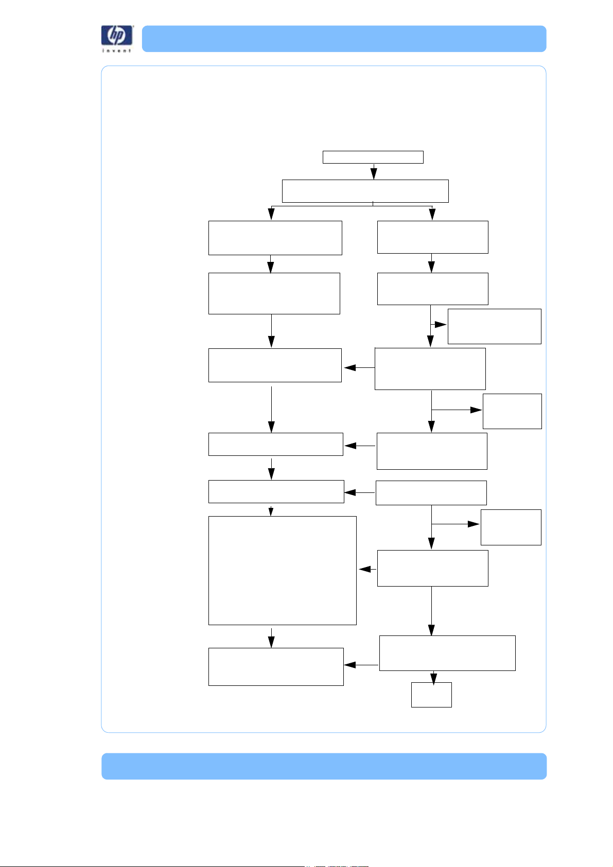
What happens when...
Powe r Switch turne d to ON
Chamber lights (dim mode), display backlight
and fans turn on. Material bay drive homes.
Performs Power On Self Test (POST).
POST looks at voltages, checksum
and memory, etc.
Performs basic hardware setup such
as checks for number of material
bays and loads gantry parameters,
etc.
Once printer software is loaded to
RAM the controller runs the POST
test again.
Controller receives updated
parameters from SBC.
Power enabled to the XYZ motors, via
the XP command.
• Chamber lights on (full power)
• Load globals
• Door locks
• Performs “Calibrate” (home) sequence:
1. Moves Z stage down to Z EOT
sensor
2. Moves head to X home (BOT) sensor
3. Moves head to Y home (BOT) sensor
4. Moves head to Y EOT sensor
Head and chamber heaters begin to
heat up, via the th, tr and tx
commands
BIOS starts and loads the OS
(operating system) from the
hard drive to the SBC RAM.
OS boots - performs check
disk (chkdsk) and loads Linux
OS from hard drive to RAM.
Loads printer software from
hard drive to RAM. SBC send
second reset (in) command to
controller.
Loads parameters to controller
(Coldfire chip) (e.g. extrusion
parameters).
SBC enables power to XYZ
motors
“Calibrate” (home) by issuing
move commands to the
controller
After chkdsk is complete,
“Copyright” screen will
be displayed.
“Starting Up”
“Initializing” is
displayed.
“Starting Up”
“Calibrating” is
displayed
“Idle” is
displayed
Controller
SBC
Commands head and chamber to
heat to “Idle” temperature (sets
temperatures)
Powering up:
Overview
-3
Page 20

Once the unit is ready to build, the display will show Idle (no part in the
queue) or Ready to build followed by the part name. Once a part is started
the appropriate liquefier will begin to heat. Once the liquefier and chamber
reach the operating temperature (310C model, 300C support, 77 Chamber)
the system will begin to build a part.
Powering Down
When the Power Switch is turned off the unit begins a controlled shut down.
The software processes are stopped and the power to the liquefier and
chamber heaters are turned off. The controller board continues to monitor
the temperature of the liquefier and the fans will continue to run. During this
time the display will show “Shutting down”. The head blower fan continues
to run to cool the liquefier down quickly to prevent back flow of material from
the liquefier. If the material is not cooled down during power down the
system may experience a loss of extrusion due to material build up at the
liquefier. Once the liquefier temperature drops below 102° C the SBC
changes the display to “Shut down” and turns off.
Loading Material
When the load material button is pressed with carriers installed the SBC will
ask the controller board to unload the carriers requested by the operator.
The most recent value for material remaining is written to the cartridge
EPROM. The material is run in reverse to unload the liquefier. When filament
is clear of the filament sensor the controller board tells the SBC that the
command is complete. The SBC sends “REMOVE CARRIER” to the
display, the carriers are unlatched, and the unit waits for you to respond.
If there are no carriers in the printer when the material button is pushed, or if
an unload has just been completed, the SBC will ask the operator to
“INSERT CARRIER”. The unit will look for a valid carrier EPROM. If there
is no change to the EPROM status in 30 seconds, you are asked if you want
to RETRY. Once valid carriers are read, the unit begins the material load
sequence.
Building a Part
How to start building a part build is dependent upon whether or not a part
is in the printer queue:
1. If a part has not been sent to the printer for building (the build queue is
empty):
A. The panel displays Idle and Queue Empty.
B. Wait for Part is blinking. Choose whether you want to start
the build process from a ‘remote’ location or from the
display panel at the printer.
-4
i. At Printer ‘Start Model’ - You send a part to the printer
from your HP Designjet 3D Software Solution work station.
You start the build of the part from the printer.
Page 21

a. Do not press the Wait for Part button
b. From your HP Designjet 3D Software Solution work
station, send a part to the printer.
c. The printer panel displays the name of the first
model in the printer queue and Start Model is
blinking.
d. From the printer, press the Start Model button to
begin building the displayed part.
ii. Remote ‘Start Model’: - You send a part to the printer
from your HP Designjet 3D Software Solution work
station. The part automatically begins to build.
a. From the printer, press the Wait for Part button
Note: Make sure an empty modeling base is installed, then answer
Yes to the prompt Is Model Base Installed?
b. Wait for Part is displayed in the upper window.
Press Cancel if you wish to exit the remote start
mode.
c. From your HP Designjet 3D Software Solution work
station, send a part to the printer. The printer will
automatically start to build the model.
3. If a part has been sent to the printer for build (there is at least one part
in the build queue), but is not building:
A. The panel displays Ready to Build.
B. The name of the first model in the build queue is displayed.
C. Start Model is blinking. Press the Start Model button to
begin building the displayed part.
Regardless of the method used to start building a part, the printer will
perform the same sequence of steps:
1. The printer drops (lowers) the substrate sensor.
2. System “touches down” six times which measures the height of the sub-
strate.
3. SBC converts the model file (CMB) into the motion commands that the
controller will execute to build the model.
4. System completes substrate measurement.
5. Z stage moves to bottom of Z travel.
6. Head moves over the purge bucket and prepares to build purging the
appropriate tip.
7. Once purge is complete, the printer will start to build the model.
During model construction, the printer will display the percentage of material
remaining on each spool. During building the keypad will allow you to
pause the printer, or turn on the chamber lights. The printer will stay in the
Building State until the model is finished or the printer pauses. If the printer
pauses, it will enter a Pending Pause state until the current road is finished.
-5
Page 22
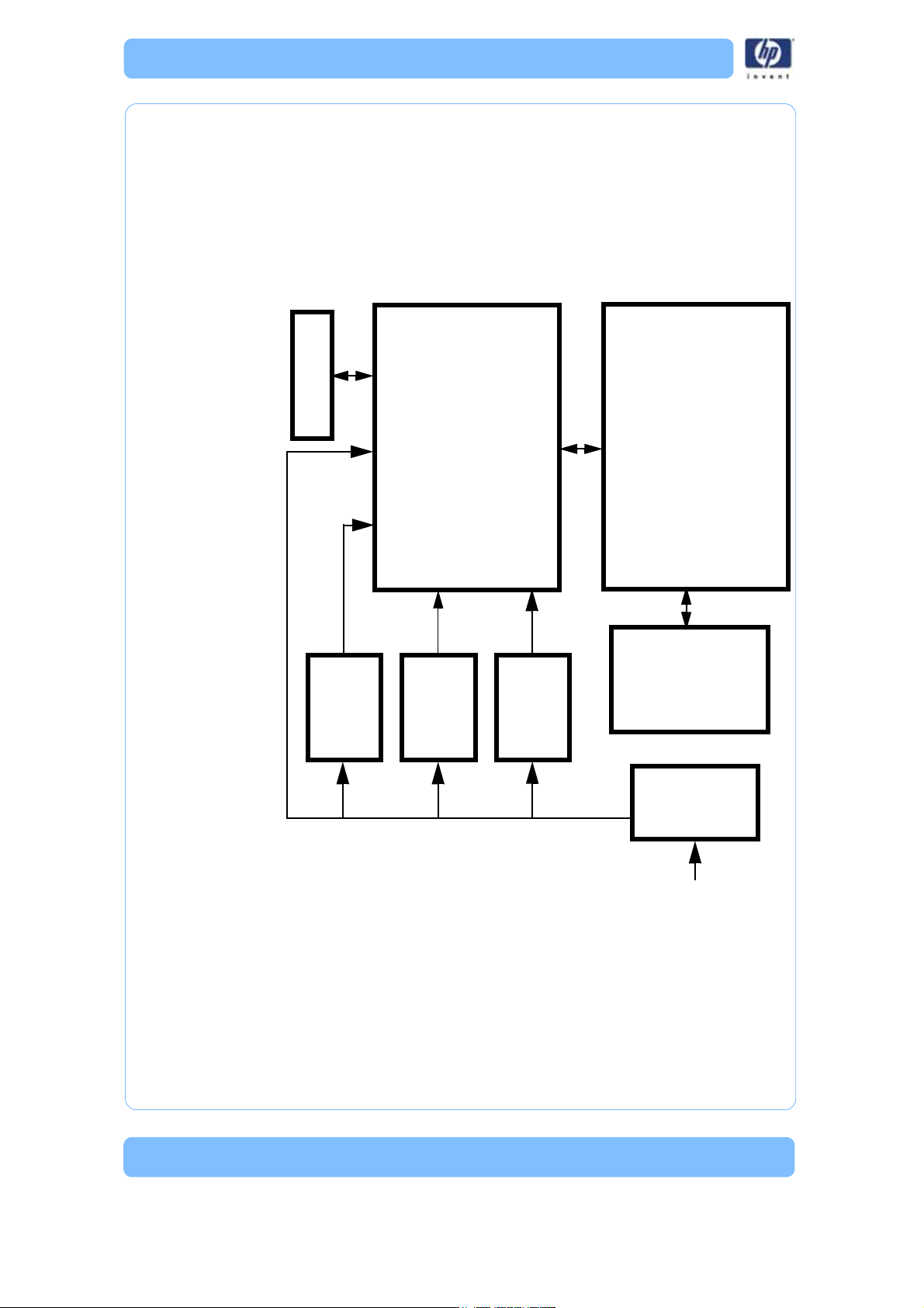
PDB
Controller
Board
SBC
AC Input
+5 and
+12 VDC
Power
Supply
Support
heater
+120
VDC
power
supply
+24 VDC
power
supply
120-240
VAC in
120-240
VAC
I/O
Once that road is complete, the head will move over the purge bucket, and
the Z stage will descend to the bottom of the envelope. In the Pause State the
printer can be resumed, material can be loaded and unloaded, the build
can be canceled, and printer maintenance may be performed.
Electronics Overview
Figure 1: Electronics Overview detail
-6
Page 23

Single Board Computer
J2 power
input
SATA
Connector
P104
Connector
Display Panel
DB-9
Connector
RJ-45
Network
Connector
The single board computer (SBC) is the main processor in the system. See
(Figure ) showing the board layout.
The TCP/IP network interface connects directly to the RJ-45 connector on the
SBC. The network interface supports both 10baseT and 100baseT operation.
The hardware differentiates automatically. There are two LED’s at the RJ-45
connector. These show the status of the network connection as follows:
• Green LED: Indicates there is a network connection present.
• Amber LED: Indicates there is a network communication.
The Hard Disk Drive (HDD) connects to the SBC with a standard IDE
interface (ribbon cable). The HDD contains the Linux operating system and
all the control software needed to run the system (except the controller
firmware). This is also where all the downloaded models are stored in the
queue.
The LCD Control Panel connects to the I/O Card. The signals then travel
though the PDB and on to the SBC. All user entered commands from the
control panel buttons are routed through the I/O and PDB and then on to the
SBC.
The P104 connector on the top edge of the board is a bus level interface to
the controller board. This allows the SBC to read and write to the dual port
ram on the controller board, which forms the communication channel
between the two boards.
Figure 2: Single board computer detail
-7
Page 24

Controller Board
Overview
The controller board provides all of the low level hardware control and
sensing for the system. The firmware runs on the controller CPU and is flash
resident (rather than on the HDD and SBC).
Voltage Generation
• +/-15 VDC is used for PMD DACs
• 10 VDC is used for DAC reference
• 3.3 VDC is used for controller board logic
Dual Port Memory Interface
The dual port memory located on the controller board provides the
communication channel with the single board computer (SBC) through the
P104 connector. The SBC provides the coordinates, velocities, and flow rate
commands for modeling to the controller. The controller board provides the
status/error information about the hardware back to the SBC.
X, Y, Z Axis Control
The controller takes the flow rate information from the SBC and sends it to
the PMD processor. The PMD 2840 processor services the X and Y stepper
motors and the model and support head servo motors. The 3410 processor
services the Z axis stepper motor. There is no feedback from the stepper
motors to the system (they are open-loop controlled).
Material Motor Control
The controller takes the flow rate information from the SBC and sends it to
the PMD 2840 processors. The PMD uses this information along with the
encoder signals from the material motors to generate an output signal to
drive the servo motors in the head assembly. Since the encoders provide
feedback the material motors have a closed-loop control. Their position and
rotation are precisely known at all times.
Temperature Control
The controller board reads the three thermocouple (T/C) inputs/signals - 2
for the head, 1 for the chamber.
-8
Page 25
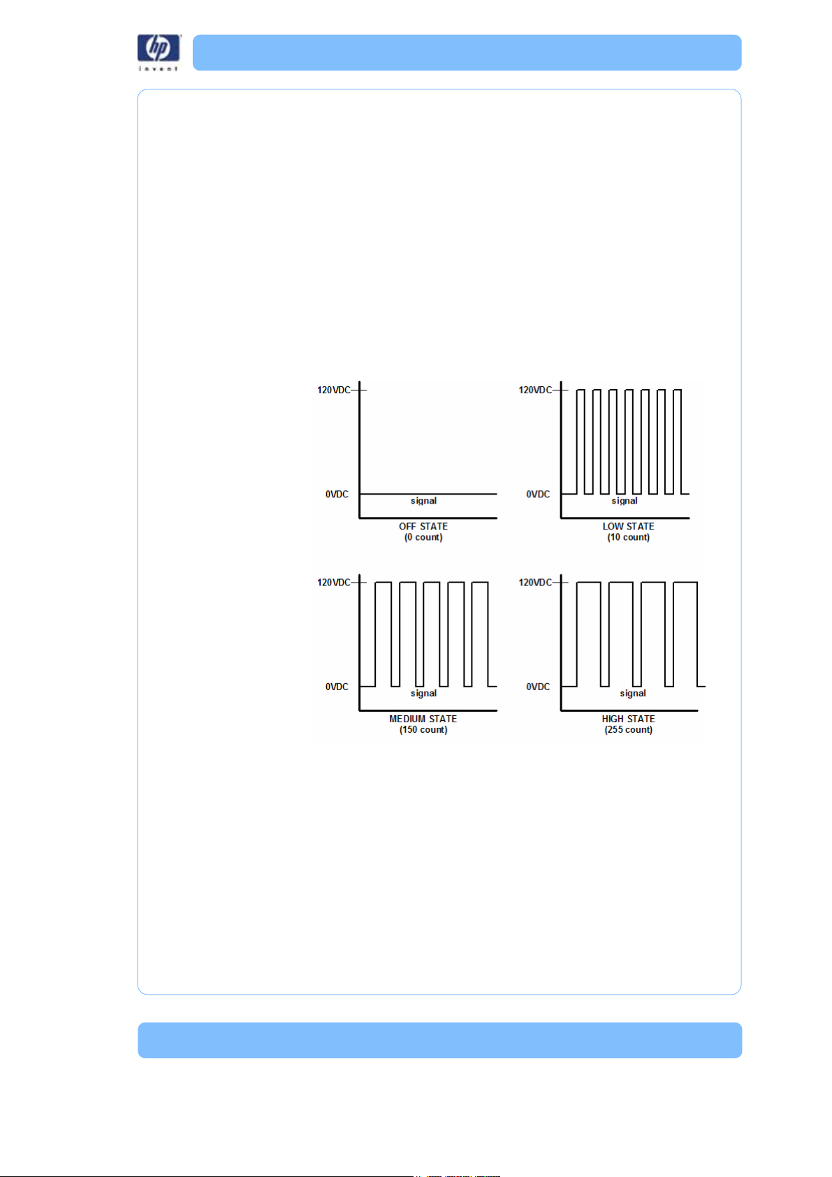
Liquefier Temperature Control
The liquefier T/C connects to the controller board through the power
distribution board. The T/C generates a variable low level current that
depends on the temperature of the T/C. This analog signal from the T/C is
amplified by the head distribution. It is then sent down the umbilical cable to
the PDB, and then to the controller board. An A to D converter in the
ColdFire chip converts the analog signal to digital. In order to improve
temperature resolution, this signal is biased. The lowest reading possible is
109.5° C. The highest reading is 330° C.
The liquefier temperature is maintained at: Model: 310 ° C, Support: 300° C
Temperature control is accomplished using “pulse wide modulation” (Figure
3).
Figure 3: Pulse Width Modulation (PWM)
Actual power to the liquefier heater is supplied by the PDB, which is
controlled by the controller board. The head heaters are turned off and on
1000 times a second (pulses). The duration of the 120 VDC pulse
determines the average power being supplied to keep the liquefier at
temperature. Temperatures can be read using a volt meter at test points TP5
for model, and TP4 support on the PDB (10 mV per degree C).
Actuators, Switches & Optical Sensors
The input and output signals are passed through the PDB and then
processed by the controller board. The non-motor actuators on a uPrint
system are 24 volt solenoids. The 24 volt power is supplied by the PDB which
-9
Page 26

in turn is controlled by the controller board. The following is a list of
actuators:
• Door solenoid – locks the door to the modeling chamber.
• Carrier latches – holds carriers in the material bays.
• Material bay solenoids – engage the motor that feeds filament from
carrier to the liquefier during auto load.
The controller board reads and updates the remaining material information
on the spool e-prom. This is accomplished through a serial interface to the
material bay encryption board. The material encryption board in turn
connects to the e-prom on the carrier/spool via two pogo pins.
The controller board monitors these switches:
• Z limit switches – upper and lower
• X end of travel (EOT) switch
• Y end of travel (ETO) switch
The controller board monitors the following optical sensors:
• X home (BOT) sensor
•Y home (BOT) sensor
• Top of modeling base sensor
Safety Devices
The controller board monitors the following safety devices:
• Chamber T/C alarm – activated for a bad or missing T/C
• Liquefier T/C alarm – activated for a bad or missing T/C
• Head and chamber “snap” switches
• Two main thermal fuses
• Door open switch
• Door latch solenoid
Controller Board Layout
(Figure 4) Shows the layout of the controller board connectors with labels
indicating where each of the functions described previously are connected.
In addition to those functions, the figure shows a reset button, a set of dip
switches, and the LEDs (D1-D3 and D6-D13).
-10
Page 27

Reset Button
Figure 4: Controller board connection detail
Located on the lower right side of the board, the reset button will do a hard
reset of the controller board. Before continuing with normal operation after
resetting the board, system power must be cycled before building. The reset
button should only be used after using Tera Term.
Dip Switches
There are three dip switch banks (SW2, SW5, SW6) located on the top right
side of the board. Dip switches are factory set and should not be changed
unless noted to be in another position.
-11
Page 28

SW2
Number (in white) Description Default
16 -24 U n us e d O f f
SW5
Number (in white) Description Default
8-15 Unused Off
SW6
Number (in white) Description Default
0 Run built-in self test (BIST) Off
1 Load Firmware (turn on when using SND-
BIN.EXE)
2 Disable door latching Off
3Unused Off
4 Don’t reset controller when in command is
issued
5 Disable WatchDog timer Off
6 Enable use of dc commands Off
7Unused Off
Off
Off
Memory
There are three types of memory contained on the controller board.
• Dual Port RAM: The communication buffer between the controller
board and the single board computer. Events (from the controller),
commands (from the SBC), and motion control vertices (from the
SBC) are passed through the P104 connector joining the two
boards.
• Flash Memory: Where the executable code resides.
Battery backup RAM; Where the controller board stores the following system
parameters:
1. Results of last power-on self test (POST)
2.Results of certain built-in diagnostic tests, if used
3.Exception trace, which is a list of the most recent exception messages
logged on the controller board
4.State information, which stores printer state when it is powered off
(includes things like the type of gantry, whether material is loaded,
the UDN, etc.).
LEDs
There are 11 LEDs located on the controller board. A grouping of three (D1D3) are located on the lower left side. The other group of eight (D6-D13) are
located on the upper right side. D1-D3 are lit when their associated voltage,
as shown in table below, is present. The 3.3 VDC supply is generated on the
-12
Page 29

controller board, +5 and +12 VDC come from the PDB. One function of the
D6-D12 LEDs is that they turn on sequentially to show software download
progress. During normal operation, D13 will blink approximately once every
two seconds to indicate that the watchdog is monitoring the system and
everything is operational.
LED Label Description
D1 +3.3 VDC Supply
D2 +5 VDC Supply
D3 +12 VDC Supply
D6-D12 Debug LEDs (software use only)
D13 Coldfire processor heartbeat
-13
Page 30

Power Distribution Board (PDB)
Figure 5: PDB Detail
AJ1AC Power In
BJ2Power Switch/Thermostat
C J3 Chamber Heaters
D J22 Auxillary 120VDC power supply
E J8 Z BOT, Z EOT, Chamber Fans, Frame ID, Filament detect
sensor (not used)
FJ9Z motor
G J10 I/O board connection
H J11 I/O board connection
IJ724VDC input
J Test points and LEDs (see detail in this section)
KJ45/12VDC input
L Voltage indicator LEDs (see detail in this section)
M J12 To material bay
N J16 To external UPS (optional)
O J18 LCD display from SBC
P J15 To controller board (ribbon cable)
Q J14 To controller board (ribbon cable)
R J13 To controller board (ribbon cable)
This board provides the power required to run the system. AC line voltage,
+5 VDC, +12 VDC, and +24 VDC feed into the PDB. An additional +120
VDC input feeds into the PDB for the support head heater.
-14
Page 31

AC line voltage comes into the PDB (Figure 5). The voltage is routed through
the solid state relay to an auto switching circuit. The circuit is used to supply
the chamber heater voltage: 240 VAC in series, or 120 VAC in parallel. The
solid state relay is controlled by the controller board, and turns the heater
on/off to regulate the chamber temperature. A second solid state relay
provides AC line voltage to the system. It is controlled by the controller board
and safely shuts down the system when the power down switch is turned off.
• The 5 VDC and 12 VDC are used by the controller board, single
board computer, and hard drive. The 12 VDC also powers the filament motors.
• The 24 VDC powers the stepper motors, solenoids, fans, and chamber lights.
• The 120 VDC circuit powers the model heater and a separate 120
VDC supply powers the support heater.
There are two fuses on the power distribution board.
• Fuse F1 fuses the AC input to the +120 VDC supply.
• Fuse F2 fuses the +120 VDC output.
Chamber Temperature Control
The chamber thermocouple (T/C) connects via the I/O board to the PDB
and is sent to the controller board. The T/C generates a variable low level
voltage that depends on the temperature of the chamber. This analog signal
from the chamber thermocouple is amplified on the I/O board and sent to
the PDB. From the amplifier, the signal goes to an A to D converter in the
ColdFire. The controller reads the chamber temperature and turns the heaters
on and off to maintain 77° C. The chamber fans run continuously when the
system is on. Temperatures can be read on the PDB using a volt meter at test
points TP22 for model, TP20 for support, and TP28 for the chamber NOTE:
10 mV = 1 degree C.
-15
Page 32

Test Points and LED’s
Test points and LED’s are very useful for troubleshooting the system. The test
points and LED’s are listed below with a brief description.
Figure 6: Test points and LEDs detail
Component Test Pt. Description
UPS TP29 Power fail signal from external UPS
+5V REF TP24 Head T/C service reference
Door Switch TP15 State of the door (open or closed)
On/Off Switch TP14 State of power down switch
Power Enable TP8 Enables power to circuitry (normally high)
Model Toggle TP17 Toggle travel complete
Chamber
Thermocouple
Support
Thermocouple
Model
Thermocouple
HD Thermostat TP25 Chamber and head thermostat (snap
Head TC Alarm TP26 High if head T/C not plugged in or open
Support Toggle TP16 Not used
Chamber TC
Alarm
TP28 Voltage corresponds to chamber temperature
(10 m V= ° C )
TP20 Voltage corresponds to support temperature
(10 m V= ° C )
TP22 Voltage corresponds to model temperature
(10 m V= ° C )
switches)
(+5 VDC if both switches closed)
Normal = tp17 lo, tp19 hi
ch thermostat fault=tp17 lo, tp19 lo.
TP27 High if chamber T/C not plugged in or open
-16
Page 33

Component Test Pt. Description
X EOT TP18 X end of travel sensor (5 VDC), switches are
wired normally closed (NC)
X Home TP19 X home sensor (5 VDC), switches are wired
normally closed (NC)
Y EOT TP12 Y end of travel sensor (5 VDC), switches are
wired normally closed (NC)
Y Home TP13 Y home sensor (5 VDC), switches are wired
normally closed (NC)
Z EOT TP10 Z end of travel sensor (5 VDC), switches are
wired normally closed (NC)
Z Home TP9 Z home sensor (5 VDC), switches are wired
normally closed (NC)
Z Substrate TP23 Z substrate sensor (5 VDC)
HD Type A TP21 Not used
HD Type B TP30 Not used
Figure 7: Voltage test points and LEDs detail
Component Test Pt. Description
+ 5 VDC TP3 + 5VDC is present
+12 VDC TP4 + 12VDC is present
+12 VDC SW TP5 + 12VDC Switching is present
+24 VDC TP6 + 24VDC is present
+24 VDC SW TP7 + 24VDC Switching is present
-17
Page 34

I/O Card
Figure 8: I/O card detail
A J510 PDB Board connection
B J511 PDB Board connection
C J507 Chamber thermocouple
DJ501Y Motor
EJ502X Motor
F J503 Y BOT and Y EOT sensors
G J504 Head blower fan, power on/off switch, left and right chamber
lights, LCD display, door solenoid, door switch.
H J505 Umbilical cable to: Model and support heaters, toggle sensor,
X BOT and X EOT sensors
I J506 Umbilical cable to: Substrate detect sensor, head drive motor,
chamber temperature alarm, model thermocouple, support
thermocouple, head temperature alarm
-18
Page 35

Head Board
G
F
J
E
K
Rear view
Front view
D
A
B
C
I
H
Figure 9: Head board layout
A J304 Z Sensor
BJ302Head Motor Power
C J303 Head Motor Ribbon Cable
D J301 Umbilical Cable
E J102 Support Heater
F U303 X Home Sensor
G J305 Toggle Sensor
H D1 Support 120VDC LED (120 VDC present if on)
I D2 Model 120VDC LED (120 VDC present if on)
J U304 X EOT Sensor
K J202 Model Heater
-19
Page 36

Printer overview
Front view
Left side view
1
6
2
3
4
5
HP Designjet 3D Printer and HP Designjet Color 3D Printer build models
from CAD STL files. The printer builds three-dimensional parts by extruding a
bead of ABS material through a computer-controlled extrusion head,
producing high quality parts that are ready to use immediately after
completion.
HP Designjet 3D Printer and HP Designjet Color 3D Printer consist of two
primary components — the 3D printer and material bay. HP Designjet 3D
Software Solution is the preprocessing software that runs on Windows XP
Pro, Windows Vista or Windows 7 platforms.
HP Designjet 3D Printer builds a maximum part size of 8 x 6 x 6 in (203 x
152 x 152 mm). HP Designjet Color 3D Printer builds a maximum part size
of 8 x 8 x 6 in (203 x 203 x 152 mm). Each material carrier contains 40 cu.
in (700 cc) of usable material — enough to build continuously for about 48
hours without reloading. You can add an optional second material bay for
extended build times.
Figure 10: Front and left side view of printer .
1Display Panel
2 Material Bay, Support Side
3 Optional Material Bay, Support Side
4 Optional Material Bay, Model Side
5 Material Bay, Model Side
6Power ON/OFF Switch
-20
Page 37

Figure 11: Interior chamber - front view
1
2
3
4
5
6
7
8
9
1Extrusion Head
2 Tip wipe assembly
3Purge bucket
4 Z stage platen
5 Modeling base retainers (x2)
6Modeling base
7 Z stage guide rods
8Z stage lead screw
9Extrusion Tips
-21
Page 38

Figure 12: Rear view of printer
1
2
3
4
5
6
7
8
9
10
11
12
13
14
15
16
1 Model Material Y Connector 9 Support Material Tube
2Model Material Tube 10 UPS Connection
3 AC Power Cord Connector 11 Material Bay Cable Connector
4 Circuit Breaker 12 RJ-45 Network Connector
5 Material Bay 13 Diagnostics Cable Connector
6 Optional Model Material Tube 14 Material Bay Communications Cable
7 Optional Material Bay 15 Optional Material Bay Communica-
8 Support Material Y Connector 16 Optional Support Material Tube
tions Cable
-22
Page 39

Figure 13: Material carriers
Support material carrier
Model material carrier
Modeling base
Figure 14: Modeling base
CAUTION: DO NOT reuse modeling bases. If a modeling base is
reused, calibration errors, poor part quality, and loss of extrusion
may occur. Additional modeling bases are available from your HP
reseller.
-23
Page 40

-24
Page 41

Setup
Set up the printer and material bay(s) per assembly instructions included with
printer.
Installing software
There are two software programs that work with HP Designjet 3D and HP
Designjet Color 3D:
1. HP Designjet 3D Software Solution, installed on your workstation,
processes the STL files for printing and communicates with the printer
from your workstation.
2. System firmware, the operating software installed on the printer, controls
printer functions.
Installing HP Designjet 3D Software Solution:
1. Locate the Startup DVD from startup kit and insert into workstation (PC).
2. Click the Install HP Designjet 3D Software Solution:
3. Follow prompts to finish loading HP Designjet 3D Software Solution on
the workstation.
button.
Installing firmware to the workstation:
1. Cl i c k t h e Install Firmware button to load firmware to your workstation.
You will be asked to load this firmware to your printer later.
2. Follow prompts to finish installing firmware on the workstation.
3. Install firmware to the printer, see “Installing Firmware on printer” on
page30.
Networking the printer
There are two methods of connecting your printer to your workstation, over a
network or with a direct connection to your workstation.
Connecting through a network:
1. Locate the network cable (blue) from the startup kit.
2. Connect the network cable between the printer and the network hub.
Connecting directly to a workstation:
1. Locate the crossover cable (orange) from the startup kit.
2. Connect the crossover cable between the printer and the network port
on your workstation.
-25
Page 42

Establishing network communication with the printer
You will need to establish network communication between your
workstation and printer before you can send files to be built. How you
establish this communication with an IP address is dependent upon how
your network and workstation are configured. If your network is configured
for DHCP (Dynamic Host Configuration Protocol), your DHCP server will
automatically assign a Dynamic IP address to your printer. This is the default
setting for your HP Designjet printer and commonly used in large networks.
In some situations you may need to manually enter a Static IP address for
your printer and record the IP address in the HP Designjet 3D Software
Solution. Static IP addresses are frequently used for smaller networks.
Follow the instructions below to configure your workstation and network.
Establishing communication on a dynamic network:
If you are on a dynamic network (or not sure of your network type) follow
these steps to allow HP Designjet 3D Software Solution to find your printer
and establish communication.
1. Connect a network cable between the printer and a network hub.
2. Make sure the printer is ON and determine the Unique Device Name
(UDN) for your printer.
A. From Idle (or Ready to Build), press Maintenance on the
display panel. The display will show Maintenance and the
software version.
B. From the display panel press System.
C. From the display panel press Set Network. The top window
will display: Network Admin - Dynamic IP Address; UDN.
D. The Unique Device Name (UDN) for your printer is listed
here. This is preset at the factory and cannot be changed.
3. From your workstation, start the HP Designjet 3D Software Solution.
4. From the General tab, click the Manage 3D Printers button.
5. Click the Add from Network button in the lower right corner of the window.
6. A new window, Add 3D Printer, should list your printer in the main win-
dow (identified by its UDN). Click on the printer in this window and
enter a name and location in the lower portion of the window.
7. C l i c k Add Printer and you are ready to print. Close the Add 3D Printer
window.
NOTE: If your printer is not displayed in the “Add 3D Printer”
window, you are not using a dynamic network and you will need to
set up a static network address.
-26
Page 43

Establishing communication on a static network:
If you are using a static network or connecting the printer directly to a
workstation, you will need to enter the static IP address information into the
workstation and the printer. If you are using a static network and your
computer already has network access, see “Setting the static network on
printer:” on page28.
1. Set the static IP address information in the workstation:
A. For Windows XP, see “Establishing communication on a
static network:” on page27.
B. For Windows Vista, see “Setting the static network in
Windows Vista:” on page27.
C. For Windows 7, see “Setting the static network in Windows
7:” on page28.
2. Set the static IP address information in the printer, see “Setting the static
network on printer:” on page28.
3. Establish communication, see “Establish communication:” on page29.
Setting the static network in Windows XP:
1. From your workstation open the Control Panel and double click on
Network Connections.
2. Right click on Local Area Connection and then left click on Properties.
3. Select Internet Protocol (TCP/IP) from the list.
4. Click on the Properties button.
5. Click on the Use the following IP address option.
6. Enter the IP Address, Subnet Mask and Default Gateway. Contact your
IT Administrator or Internet Service Provider for details regarding IP
address information.
7. Cl i c k o n t h e OK button when finished. Close any open networking win-
dows.
Setting the static network in Windows Vista:
1. From your workstation click on the Start Menu.
2. Click on the Control Panel button.
3. Double click on Network and Internet.
4. Double click on the Network and Sharing Center icon.
5. Left click on Manage network connections.
6. Right click on the Local Area Connection icon then left click on Proper-
ties.
7. S e l e c t Internet Protocol Version 4 (TCP/IPv4) from the list.
8. Click on the Properties button.
9. Click o n the Use the following IP address option.
-27
Page 44

10. Enter the IP address, Subnet Mask and Default Gateway. Contact your IT
Administrator or Internet Service Provider for details regarding IP
address information.
11. C l i c k o n t h e OK button when finished. Close any open networking windows.
Setting the static network in Windows 7:
1. From your workstation click on the Start Menu.
2. Click on the Control Panel button.
3. Double click on Network and Internet.
4. Double click on the Network and Sharing Center icon.
5. Double click Local Area Connection.
6. Click on the Properties button.
7. S e l e c t Internet Protocol Version 4 (TCP/IPv4) from the list.
8. Click on the Properties button.
9. Click o n the Use the following IP address option.
10. Enter the IP address, Subnet Mask and Default Gateway. Contact your IT
Administrator or Internet Service Provider for details regarding IP
address information.
11. Click on the OK button when finished. Close any open networking windows.
Setting the static network on printer:
1. Obtain your static network address from your Network Administrator.
2. From Idle (or Ready to Build), press Maintenance on the display panel.
The display will show Maintenance and the software version.
3. Press System.
4. Press Set Network. The top window displays: Network Admin - S tatic IP
Address; UDN.
5. Press Static IP to display default settings.
IP Address:172.016.075.020 or 198.000.000.001
NM Address:255.255.000.000
GW Addres s : 172.018 .100.002
NOTE: These values are the factory defaults and MUST be
changed. If these values are not changed the printer will continue
to restart until they are changed.
6. Update the IP address:
Press Increment to increase the value one digit at a time.
Press Next Digit to move the cursor one place to the right.
Press Last Digit to move the cursor one place to the left.
7. Use the three functions listed above to set your IP address.
8. After setting the final digit of the Internet Protocol (IP) address, move the
cursor one more place to the right. The cursor moves to the Netmask
-28
Page 45

(NM) address. Follow the same steps for setting the Netmask (NM) and
Gateway (GW) addresses.
9. When you have finished setting the addresses, press Done. The display
will show: Change IP, Netmask and Gateway?
10. Pre ss Yes. The panel then displays Resetting Network.
11 . P r e s s Done until Idle is displayed.
Establish communication:
1. From your workstation, start the HP Designjet 3D Software Solution.
A. From the General tab, click the Manage 3D Printers button.
B. Click the Add from Network button in the lower right corner
of the window.
C. A new window, Add 3D Printer, should list your printer
(identified by its UDN). Click on the printer in this window
and enter a name and location of your choice in the lower
portion of the window.
D. Click Add Printer to complete. Close the Add 3D Printer
window.
2. If your printer is not displayed in the Add 3D Printer window, you will
need to add the printer IP address manually.
A. From the General tab, click the Manage 3D Printers button.
B. Click the Add Manually button in the lower right corner of
the window.
C. In the Add 3D Printer window, enter a name and location
of your choice in the appropriate fields.
D. Enter the IP Address for your printer in the appropriate field.
It will be the same address as entered in step 6.
E. Select your printer type from the drop down list, either HP
Designjet 3D or HP Designjet Color 3D.
NOTE: If you only have one printer connected, it will be the only
printer in the list.
F. C li ck Add Printer and close the Add 3D Printer window.
3. If you are unable to connect the printer to your workstation, contact your
Network Administrator.
-29
Page 46

Installing Firmware on printer
1. From the display panel, press Maintenance.
2. Press System.
3. Press Load Upgrade. “Send upgrade from workstation” and the printer
IP address will be displayed.
4. From your workstation, open the HP Designjet 3D Software Solution by
double clicking on the HP Designjet 3D Software Solution icon.
5. Click the Printer Services tab.
6. Select your printer from the drop down list then click the Update Soft-
ware button.
7. Navigate the HP Designjet 3D Software Solution to the directory where
the firmware file is located and select the HP Designjet 3D.upg file for
HP Designjet 3D or select the HP Designjet Color 3D.upg file for HP
Designjet Color 3D. Firmware will now begin to download to the printer.
NOTE: The printer will not allow a firmware upgrade file for a
different type of printer. If an upgrade file that is incorrect,
“Upgrade - Invalid Upgrade” will be shown on the display panel.
8. When firmware verification is complete, the printer display will show
Reboot to complete upgrade? Press Yes. The printer will then load the
firmware then reboot and return to Idle.
NOTE: Loading firmware will take approximately 10 minutes.
-30
Page 47

Adding the second HP Designjet 3D Material Bay
You have the option of adding a second material bay to extend printing
times without having to reload material while the model is printing.
Installing the HP Designjet 3D Material Bay:
1. Remove the HP Designjet 3D Material Bay, material bay cable, material
spools and material carriers from the box.
2. Unload the model and support material from the printer.
3. Open the material bay doors by gently pressing in to release and pull-
ing outwards.
4. Remove the material carriers by first pushing them in to unlatch and then
pulling them outwards.
5. Place the carriers on a flat stable surface.
CAUTION: Do not push the material through the material guide
back into the carrier, doing so can cause material to break or
become tangled.
6. Open the carriers.
7. Rotate the spools to rewind the material, leaving 2 inches (50mm)
remaining at the material guide. See Figure 15.
Figure 15: Rewinding the material spool
8. Using a cutters, cut the excess 2 inches (50mm) of material from the
material guide. leaving a blunt end.
9. Power the printer off at the power switch.
10. When the printer has powered down, switch the circuit breaker to the
OFF position.
11. Disconnect the power cable, network cable, material bay cable and
UPS cable if used.
12. Disconnect the model and support material tubes from the printer and
the material bay by pressing in on the coupler ring and pulling the tubes
outward.
13. With 2 people, use the handgrips to lift the printer off of the material
bay and place on a flat stable surface. See Figure 16.
-31
Page 48

Figure 16: Separating the printer and material bay
14. Position the second material bay on top of the existing material bay. Be
sure the feet and pins are properly aligned. See Figure 17.
Figure 17: Positioning material bays
-32
15. With 2 people, position the printer on to the top of the material bays. Be
sure the feet and pins are properly aligned. See Figure 18.
Page 49

Figure 18: Positioning printer
16. Remove the black plugs from the model and support Y blocks by push-
ing in on the coupler rings and pulling outward. See Figure 19.
Figure 19: Removing the Y block plugs
17. Connect the short red striped material tube (M1) from model (M) coupler
of upper material bay to left side of model Y block by inserting firmly
into red couplers. Gently pull the tube to ensure it is properly inserted.
18. Repeat with the short black striped (S1) material tube for support side.
See Figure 20.
-33
Page 50

Figure 20: Connecting the short material tubes
19. Connect the long red striped material tube (M2) from model (M) coupler
of lower material bay to right side of model Y block by inserting firmly
into red couplers. Gently pull the tube to ensure it is properly inserted.
20. Repeat with long black striped (S2) material tube for support side. See
Figure 21.
Figure 21: Connecting the long material tubes
21. Connect a material bay cable between the printer and the top connector
on the upper material bay.
22. Connect the other material bay cable between the bottom connector of
the upper material bay to the top connector of the lower material bay.
See Figure 22.
-34
Page 51

Figure 22: Connecting the material bay cables
23. Connect the power cable, network cable and UPS cable if used.
24. Switch the circuit breaker to the ON position.
25. Power the printer ON at the power switch.
26. After the printer has booted up, you may need to reload the printer firm-
ware. If the printer displays “Send Upgrade from Workstation”, See
“Updating printer firmware:” on page 53.
27. Insert model and support material spools into the new material carriers.
28. From display panel press Material. Display will show Add/Remove.
29. Open material bay doors and push both red handled model carriers
into right side of the material bays until they latch.
30. Push both black handled support carriers into left side of the material
bays until they latch.
31. P r e s s Load Selected. The printer will load the first material bay and pre-
pare the second material bay for automatic loading. When the printer
has finished loading material, S1 and M1 will be marked with asterisks.
All material bay LED’s will be solid.
NOTE: Material may take up to ten minutes to load.
32. When finished loading material press Done. Display will show Idle and
amount of material remaining for model and support in both material
bays.
-35
Page 52

-36
Page 53

Operation
Upper window
Lower windows
Keypad buttons
Display panel and keypad
The main user interface for the printer is the display panel and keypad. See
Figure 23.
Figure 23: Display panel and keypad
The HP Designjet 3D and HP Designjet Color 3D display panel and keypad
consist of a multiple-line LCD window with two buttons used for scrolling
through messages and four single-line windows, each with one button for
making selections. The top line in the upper window always shows the
printer status.
NOTE: If an item is blinking in the lower displays, the blinking item
is usually the next most logical selection.
-37
Page 54

Idle
Standby
Maintenance
Machine
• Set Network
• Test Parts
• Load Upgrade
• Lights Always On
• Select Language
• Gantry
• Head
• Tips
Building
• Pause
• Lights Off
• Show Time
• Auto Power Down
• Load Material
• Unload Material
• Replace Material
Wait for Part/Start Part
System
Setup
Material
System firmware overview
• Idle: If there is no part being built and no part in the build queue,
the display will show that the printer is Idle.
• Wait for Part or Start Part: If the printer is in Idle and the build
queue is empty, you can set it to wait for a part. If the printer has a
part in the build queue, you can press Start Part to start a build.
• Building: If the printer is building a part, you can choose to pause,
set the lights either ON or OFF, view the print time or material
remaining and set the printer to auto power down.
• Material: From this section you can load material, unload material
or replace material.
• Standby: From this section you can set the printer to Standby mode.
• Maintenance: From this section you can make changes to the Sys-
tem, Setup or Machine.
Figure 24: Display panel hierarchy
-38
Page 55

HP Designjet 3D Software Solution
HP Designjet 3D Software Solution
• Auto orientation
• Part rotation
• STL scale
• Change views
• Insert Pause
• Insert CMB file
• Pack name
• Clear pack
• Printer status
• Job queue
• Manage queue
• Printer history
• Export configuration
• Printer time
• Printer password
• Printer information
• Update software
• Layer resolution
• Model fill style
• Support style
• Number of copies
• STL units
• STL scale
General tab
Orientation tab
Pack tab Printer Status tab
Printer Services tab
overview
• General tab: This section is where you can select the model fill, sup-
port style, change the STL units and STL scale.
• Orientation tab: This section allows you to rotate, resize and auto-
orient your parts. You can also change the view and insert a pause.
• Pack tab: This section shows you which parts are in the pack for
printing. You can add parts, arrange the parts for a better fit or
clear the pack from this section.
• Printer Status tab: This section shows you the amount of material
remaining (both model and support) as well as which parts are in
the Build Queue.
• Printer Services tab: From this section you can check the printer his-
tory, set the printer time, set the printer password, update printer
software, get printer info and export configuration files (files containing specific operating information regarding the printer).
Figure 25: HP Designjet 3D Software Solution hierarchy
NOTE: For detailed information refer to HP Designjet 3D Software
Solution Dynamic Help.
-39
Page 56

Processing your STL file for printing
Opening your STL file with HP Designjet 3D Software Solution:
1. Create an STL file using your CAD software. Refer to your CAD software
help section for more information about converting your CAD drawings
into STL files.
2. Open the HP Designjet 3D Software Solution.
3. From the File menu select Open STL...
4. Navigate to and select the STL file that you have created.
Selecting layer resolution:
Layer resolution can be changed on the HP Designjet Color 3D printer.
Changing layer resolution will affect surface finish and build times. Selecting
a smaller layer resolution creates a smoother surface finish, but takes longer
to build. Layer resolution also affects the minimum wall thickness. Minimum
wall thickness applies to the horizontal (XY) plane of your part. If a feature
in an STL is smaller than the limit, the modeler will increase the size of the
feature to the minimum wall thickness.
Printer type Available layer resolutions Min. wall thickness
HP Designjet 3D .010 inch (.254 mm) .036 inch (.914 mm)
HP Designjet Color 3D .010 inch (.254 mm)
.013 inch (.3302 mm)
.036 inch (.914 mm)
.047 inch (1.194 mm)
Selecting model interior fill style:
This establishes the type of fill used for the interior areas of the part. There
are three types of model interior that you can choose from.
• Solid - Used when a stronger, more durable part is desired. Build
times will be longer and more material will be used.
• Sparse High Dens ity - This is the default model interior style and
is highly recommended. Build times will be shorter, less material will
be used and the possibility of part curl for geometries with large
mass will be greatly reduced.
• Sparse Low Density - The interior will be “honeycombed” or
“hatched”. This style allows for the shortest build times and lowest
material usage but will decrease the strength of the part.
-40
Page 57

Selecting support style:
Support material is used to support the model during the build process. It is
removed when the part is complete. Support styles will affect the support
strength and build time of the print. SMART support is the default support
setting as it uses the least amount of support material and allows for faster
build times.
• Basic - May be used for most parts. Basic support uses a consistent
spacing between support toolpaths.
• SMART - minimizes the amount of support material used, reduces
the build time, and improves support removal for many parts.
SMART supports use a wide spacing between toolpath rasters and
change the shape of the support region. As the supports descend
from the underside of the part feature to the base of the supports,
the support region shrinks and transforms to a simpler shape to
reduce the amount of material used and the build time. SMART supports are suitable for all parts, especially those with large support
regions.
• Surround - The entire model is surrounded by support material.
Typically used for tall, thin models.
Selecting the scale of your STL file:
Before you process a part for printing, you can change the size of the part
within the build envelope. Every part has a pre-defined size within the STL
file. After you have opened the file you can change the size of the part
produced from the STL file by changing the scale. The scale always relates to
the original STL file size definition.
For example: a cube that is defined as 2 X 2 X 2 can be built to be 4 X 4 X
4 by simply changing the scale to 2.0. If after changing the scale to 2.0, you
decide that a size of 3 X 3 X 3 would be preferred, change the scale to 1.5 the scale relates to the original size of 2.0, NOT the resulting 4.0 from the
first scale change.
Click within the scale input box to type a scale of your choice.
Selecting the orientation of your STL file:
The Orientation tab has an expanded preview window. It provides options
for viewing a part, measuring a part, orienting a part, processing a part and
viewing the layers of a part. How a part is oriented in the preview window
will determine how the part is oriented when it prints.
Orientation impacts build speed, part strength, surface finish and material
consumption. Orientation can also affect the ability of HP Designjet 3D
Software Solution to repair any problems with the STL file.
You can choose to auto orient your part, which allows HP Designjet 3D
Software Solution to determine the best orientation for the part for the fastest
build time and least material usage, or you can manually change the
orientation of your part.
-41
Page 58

Orientation Considerations:
• Build Speed - Closely related to material use. A lesser amount of
supports will allow for a faster build speed.
Another factor affecting build speed is the axis orientation. The
printer can build faster across the X-Y plane than it can along the Z
axis. Orienting a part so that it is shorter within the modeling envelope will produce a quicker build.
• Part Strength - A model is stronger within a layer than it is across
layers. Depending upon what features you want your part to demonstrate, you may need to orient your part to have its greatest
strength across a specific area. For example a tab that needs to be
pressed would be weakest if you are applying pressure across layers.
• Surface Finish - Much like orienting for strength, how the part is
oriented will determine how the surface finish will look and allow
the printer to provide the smoothest finish for a specific area. For
example, if building a cylinder, orienting the cylinder upright will
have a smoother surface finish than building it on its side.
• STL File Repair - It is possible for an STL file to have errors while
appearing to be trouble free. If the STL file contains errors, HP
Designjet 3D Software Solution may have problems processing the
file. HP Designjet 3D Software Solution has the ability to automatically correct some STL file errors. How the part is oriented can
impact this automated repair function.
Adding your STL file to the pack:
The Add to Pack button is found on the General, Orientation and Pack tabs.
When you click on the Add to Pack button, HP Designjet 3D Software
Solution will add the file that is currently in the preview window (General tab
or Orientation tab) to the pack preview window (Pack tab).
If the file in the preview window has not been processed for printing,
processing will occur before the file is added to the pack. Each additional
click of the Add to Pack button will add another copy of the file to the pack.
Printing your STL file:
The Print button is found on the General, Orientation and Pack tabs.
HP Designjet 3D Software Solution will now process all parts in the pack
and create a CMB file from which the printer will print the parts.
-42
Page 59

Building a part
If a part has not been sent to your printer for building, the build queue will
be empty. If the build queue is empty the display panel will show Idle or
Ready to build.
Choose whether or not you want to start a build from a remote location or
from the display panel at the printer.
Starting a build from a remote location:
The lower display will show Wait for Part and it will be flashing.
1. From the display panel press Wait for Part. The display will ask Is
Model Base Installed?
2. Insert a modeling base.
CAUTION: DO NOT reuse modeling bases. If a modeling base is
reused, calibration errors, poor part quality, and loss of extrusion
may occur. Additional modeling bases are available from your HP
reseller.
3. Press Yes. Waiting for Part will now be on the display.
4. From your HP Designjet 3D Software Solution workstation, send a part
to the printer. The printer will automatically start to build the part.
Starting a build from the display panel:
If Wait for Part has not been activated, you can send the part to the printer
and start the part from the display panel after the part has been sent to the
printer.
1. From your HP Designjet 3D Software Solution workstation, send a part
to the printer. The display will show Idle/Ready to Build and the name of
the first file that is in the queue waiting to be built.
2. Insert a modeling base.
CAUTION: DO NOT reuse modeling bases. If a modeling base is
reused, calibration errors, poor part quality, and loss of extrusion
may occur. Additional modeling bases are available from your HP
reseller.
3. From the display panel press Start Model to start building the part.
-43
Page 60

Printer status
Model file name
Support material
remaining
Model material
remaining
Printer status
Model file name
Support material
remaining in bay 1
Support material
remaining in bay 2
Model material remaining
in bay1
Model material remaining
in bay2
Single material bay
Dual material bay
The display panel during build
The top two lines of the display panel will show the printer status. See Figure
26. The bottom line of the display panel will show the amount of model and
support material that remains in the carriers.
Figure 26: Display panel during build
NOTE: If a material amount is flashing, it indicates that the
remaining material will not be enough to complete the current build.
Chamber Lights
When a part starts to build, the chamber lights are automatically ON. The
default time-out for the lights is 30 minutes. You can toggle the lights ON or
OFF through the display panel.
You can set the chamber lights on permanently, however the chamber lights
will return to factory settings when power is cycled.
1. F r o m Idle or Ready to Build, on the display panel press Maintenance.
2. Press Setup.
3. Press Lights Always On.
Repeat this process to turn this option off.
-44
Page 61

Pausing a build
While building a part, you may want to pause the build to allow for material
replacement. To pause the build at any time, from the display panel press
Pause.
NOTE: The printer will complete the current tool path before
pausing.
Resuming after pause
If you have pressed Pause, and are ready to resume building the part, press
Resume and the printer will resume printing.
Canceling a build
You can cancel a build at any time while the part is building.
1. From the display panel press Pause.
2. Once the printer stops building, press Cancel Build.
3. The display will ask Are you Sure? Press Yes.
4. The display will show Build Stopped followed by the file name. You will
then be prompted to remove the part and replace the modeling base.
5. Remove the part and replace the modeling base.
GLOVES: The modeling base will be hot, wear gloves when
removing the part from the printer.
6. Once the chamber door has been opened and closed, the display will
ask Part Removed? Press Yes ONLY after you have removed the part
and replaced the modeling base.
CAUTION: If you press Yes before removing the part, the printer
can be damaged.
-45
Page 62

Removing a completed par t
When the printer has completed building a part, the display will show
Completed followed by the file name. It will also show Remove Part and
Replace Modeling Base.
GLOVES: The modeling base will be hot, wear gloves when
removing the part from the printer.
1. Open the chamber door.
2. Turn the modeling base retainers down and remove the modeling base
by sliding out and pulling up.
3. Insert a new modeling base by sliding in and pushing down, turn the
retainers up to lock the modeling base in place.
4. Close the chamber door.
5. After you have opened and closed the door, the display will show Part
Removed? ONLY after removing the part and replacing the modeling
base, from the display panel press Yes.
CAUTION: If you press Yes before removing the part, the
printer can be damaged.
After you press Yes, the display will show the status as Idle or Ready to Build
for the next part in the queue.
Remove a part from the modeling base:
1. After removing the modeling base from the printer, firmly flex the
modeling base back and forth with your hands to loosen the part.
2. Pull the part off of the modeling base or use a putty knife to completely
remove the part.
NOTE: Parts are easier to remove from the modeling base when still
warm.
Removing support material
HP Designjet 3D and HP Designjet Color 3D use soluble support material
which is designed to dissolve in a soap and water based solution. Your part
is left with a smooth and clean finish with the fine details intact. The soluble
support material can be removed by hand with relative ease, but is designed
to be dissolved from your parts for hands free finishing.
WARNING: Support material is sharp, wear safety glasses and
gloves when removing support material.
-46
Page 63

Emptying the purge bucket
Purge bucket
Empty the purge bucket after each build to avoid part quality issues or
damage to the printer.
GLOVES: Wear gloves when emptying the purge bucket.
1. With a gloved hand, lift up on the purge bucket and pull it off of the two
mounts. See Figure 27.
Figure 27: Emptying the purge bucket
2. Empty the purge bucket.
3. Place the purge bucket over the two mounts and push down to lock in
place.
CAUTION: When reinstalling the purge bucket, make sure that it
locks on both mounts and hangs flush with the chamber wall to
avoid damage.
Replacing material for single material bay
1. From the display panel press Material... The display will show Add/
Remove and S1(remaining%) and M1(remaining%). Asterisks will
mark the currently active material bays (the material bays that are
currently loaded to the head).
2. Press Unload...
3. Select Unload both, Unload Model or Unload Support.
4. The printer will now unload material from the head. When the material
has unloaded, you will need to replace the material carriers.
5. Open the material bay doors by gently pressing in to release and pull-
ing outwards.
-47
Page 64

6. Remove the material carriers by first pushing them in to unlatch and then
pulling them outwards.
7. Place the carrier on a flat stable surface.
CAUTION: Do not push the material through the material guide
back into the carrier, doing so can cause material to break or
become tangled.
8. Open the carrier.
9. Rotate the spool to rewind the material, leaving 2 inches (50mm)
remaining at the material guide. See Figure 28.
Figure 28: Rewinding the material spool
10. Using a cutters, cut the excess 2 inches (50mm) of material from the
material guide. leaving a blunt end.
11. Replace the material spool.
12. Close and latch the carrier.
13. Once the material carriers have been replaced press Load...
14 . S e l e c t Load Model, Load Support or Load both.
15. After material has been loaded to the head press Done...
Replacing material for dual material bays
1. From the display panel press Material... The display will show Add/
Remove and S1(remaining%), S2(remaining%) and M1, M2
(remaining%). Asterisks will mark the currently active material bays (the
material bays that are currently loaded to the head).
2. Press Unload...
3. Press Unload both, Unload Model or Unload Support.
4. The printer will now unload material from the head. When the material
has unloaded, you will need to replace the material carriers.
5. Open the material bay doors by gently pressing in to release and pulling outwards.
6. Remove the material carriers by first pushing them in to unlatch and then
pulling them outwards.
-48
Page 65

7. Place the carrier on a flat stable surface.
CAUTION: Do not push the material through the material guide
back into the carrier, doing so can cause material to break or
become tangled.
8. Open the carrier.
9. Rotate the spool to rewind the material, leaving 2 inches (50mm)
remaining at the material guide. See Figure 29.
Figure 29: Rewinding the material spool
10. Using a cutters, cut the excess 2 inches (50mm) of material from the
material guide, leaving a blunt end.
11. R e p l a c e t h e m a t e r i a l s p o o l .
12. Close and latch the carrier.
13. Once the material carriers have been replaced press Load...
14. You can select which carriers you want to load to the head by selecting
Next Model or Next Support. When done selecting press Load Selected.
15. The printer will now load the selected material bays and prepare the
other bays for automatic loading. After they are done loading and preparing, press Done... the display will show Wait for Part or Ready to
Build.
Material bay LEDs
The table below will show the status indicated by the LEDs.
On
Off
Blinking
Material currently loaded to the head
No carrier present
Carrier present and ready to be loaded
Carrier needs replacement (is empty or has an
error)
-49
Page 66

Replacing material spools
Removing a spool of material from the carrier:
1. Place the carrier on a flat stable surface.
2. Unlatch the carrier and open.
3. Remove the spool of material. Discard any pieces of material
that may re main in the carrier.
4. Remove the material guide and recycle.
5. Recycle the empty material spool.
6. Install a new material spool into the material carrier.
Storing material spools
If you will not be using the printer for more than 72 hours, unload and store
model and support material in the storage bags provided to prevent moisture
absorption.
1. Unload material from the printer.
2. Open the material bay doors by gently pressing in to release and pulling outwards.
CAUTION: Do not push the material through the material
guide back into the carrier, doing so can cause material to
break or become tangled.
3. Remove the material carriers by first pushing them in to unlatch and then
pulling them outwards.
4. Place the carrier on a flat stable surface.
5. Open the carrier.
6. Rotate the spool to rewind the material, leaving 2 inches (50mm)
remaining at the material guide. See Figure 30.
-50
Page 67

Figure 30: Rewinding the material spool
Material retaining clips
7. Using a cutters, cut the excess 2 inches (50mm) of material from the
material guide, leaving a blunt end.
8. Locate the two material retaining clips on the carrier. See Figure 31.
Figure 31: Material retaining clips
9. Place the material guide in the material guide slot on the spool. See Fig-
ure 32.
10. Place the material in the material notches. See Figure 32.
Figure 32: Material guide slot and notches
-51
Page 68

11. Cut the excess material from material guide.
Place clip and push down to lock in place
12. Place the material retaining clips on the spool before removing the spool
from the carrier. See Figure 33.
A. Push the material retaining clips over the material and clip
on to the material spool.
B. Push the material retaining clips down until they lock in
place.
Figure 33: Installing material retaining clips
13. Remove the material spool from the material carrier. See Figure 34.
Figure 34: Properly installed material retaining clips.
14. Place the material spool in the storage bag that came with the material
carrier.
NOTE: When not loaded in the printer, always store material spools
in the material carrier or the storage bag that came with the carrier
to prevent moisture absorption.
Auto power down
You can set the printer to automatically power down when a build is
complete. This option will save energy usage.
1. While the printer is building, press the Auto Power Down button.
2. Turn the power switch, located on the left side of the printer, to the OFF
position.
The printer will display Auto Power Down Mode and the printer will power
down as soon as the build is complete.
Cancelling auto power down:
1. Turn the power switch back to the ON position.
-52
Page 69

Powering off
To power off the printer, turn the power switch to the OFF position. You can
do this at anytime without harming the printer. No other steps are necessary.
If this is done while the printer is building a part, the current part will not be
completed.
NOTE: System cooling fans and lights will continue to operate for
several minutes after the switch has been turned off.
Resuming operations from Standby mode
After several minutes of inactivity, the printer will enter Standby mode.
During Standby, the head temperature will decrease to conserve energy.
From the display panel press Resume.
Updating printer firmware:
Check http://www.hp.com for printer firmware updates. If there is an
upgrade to the printer firmware, download the upgrade and install on the
printer.
Installing the firmware:
1. From the printer display panel, press Maintenance.
2. Press System.
3. Press Load Upgrade. The printer will then display “Se nd up grade from
workstation” followed by the printer’s IP address.
4. Open HP Designjet 3D Software Solution and click on the Printer Ser-
vices tab.
5. Click on the Update Software button. HP Designjet 3D Software Solution
will now connect to the printer and will prompt you to locate the
upgrade file. Navigate HP Designjet 3D Software Solution to the directory where the upgrade file is located. The update will automatically be
loaded on to the printer. After the update has been loaded, the display
will show Verifying update.
6. When verification is complete, the display will show Reboot to complete.
Press Yes. The printer will now reboot and return to Idle.
7. P r e s s t h e Maintenance button and verify the updated version was
installed correctly then exit maintenance.
-53
Page 70

-54
Page 71

Software
Software Architecture
(Figure 35) shows the major software components that control the system.
The software that runs on the controller board is EPROM based. The
software that runs on the SBC (single board computer) is stored on the hard
drive and loaded during power up. Like all workstation compatible
computers, the SBC runs a brief self-test on power up and then loads the
operating system followed by the system’s application components.
Figure 35: Software Architecture Diagram
Operating System
The printer’s software currently runs on RedHat Linux. The operating system is
multi tasking allowing the software components to run fairly independently.
The operating system also provides support for the TCP/IP network interface
and the hard drive.
Display Driver
This software interacts with the operator display panel on the front of the
system. This software processes all button pushes. The driver also formats the
information going to the four line display and the context sensitive button
labels.
-55
Page 72

Comm Server
The comm server software on the system is the other half of the download
software that is part of the HP Designjet 3D Software Solution. Parts to be
built (.cmb files) are received by the comm server and saved on the data
partition of the hard drive. Queue management of the parts to be built is
also part of the comm server. Lastly the comm server provides HP Designjet
3D Software Solution the printer status information that is displayed on the
workstation (PC).
System Manager
The system manager software provides the overall control and decision
making functions that are used by the system during all operations. User
requests are received from the display driver (in response to button pushes).
The requests are processed and commands sent to the controller board to
activate the appropriate hardware.
Move Compiler
When “Start Part” is requested the system manager activates the move
compiler. The move compiler retrieves the cmb file from the top of the queue.
The CMB file defines the tool path for the part on a layer by layer basis. The
move compiler calculates the proper extrusion rate for the road thus
combining tool path and extrusion. The resulting motion control is saved in a
PCB file.
Feeder
This driver takes the output of the move compiler and feeds the motion
control information to the controller board on demand. The feeder will
typically start before the move compiler has finished the calculations for the
part. This eliminates waiting for all calculation to be complete. As the
controller board executes the motion control commands they are removed
from dual port memory. The feeder adds new commands as space becomes
available.
Event/Command Monitor
This software handles all non-motion control interactions between the single
board computer and the controller board. Events are printer status
information being sent to the single board computer. Commands come from
the single board computer telling the controller board to do something such
as find home.
-56
Page 73

HP Designjet 3D Software Solution Help
HP Designjet 3D Software Solution overview
HP Designjet 3D Software Solution is an intuitive, user-friendly application
designed to interface with HP Designjet 3D printers. It allows you to quickly
and easily open a 3D drawing of a part, prepare the drawing for print, and
send the print command to create the part.
HP Designjet 3D Software Solution provides 'Help' information in two ways through a conventional help file and through a Dynamic Help system.
Conventional help file
The entire Help file is accessible through the menu bar (Help>Contents). This
will open HP Designjet 3D Software Solution help in a separate window
containing standard help tools - table of contents, search, index, and
personally selected favorites.
Dynamic help
Dynamic Help is available from within the HP Designjet 3D Software
Solution window. The right side of the application window is dedicated to
Dynamic Help.
-57
Page 74

-58
Page 75

Maintenance
Startup kit tools
The startup kit contains a set of tools used to help you maintain the printer.
The following is a list of the tools contained in the startup kit.
• Needle nose pliers
• T-Handled allen wrench - 1/8 inch
• T-Handled allen wrench - 7/64 inch
• Gloves (Leather)
•Cutters
•Brush
•Magnifier
Preventive Maintenance
Daily
Empty the purge bucket
Empty the purge bucket after each build has completed.
Inspect the tip wipe assembly
After each build you should inspect the tip wipe assembly to make sure there
is no material build up. If there is material build up, clean the tip wipe
assembly. Material build up on the tip wipe assembly can cause part quality
issues. See “Tip wipe assembly” on page60.
Inspect the tip shields
After each build you should inspect the tip shields for damage or material
build up. If there is material build up remove it as needed. If the material will
not break free or there is damage to the tip shield, replace the tip shield. See
“Tip shield replacement” on page62.
Remove debris buildup
Remove all material buildup on the Z platform and around the lead screw.
Failure to do so could cause the base to not be level or the Z platform to jam
at its upper limit.
Vacuum build chamber
Vacuum the build chamber to remove all debris and purged material.
Clean door
Do not use ammonia based glass cleaner on the door. It will damage the
acrylic window.
CAUTION: ONLY use acrylic cleaner.
-59
Page 76

500 Hour maintenance
Preventive Maintenance Alerts will be displayed on the workstation at the
500 hour time interval as a reminder to perform preventive maintenance.
See Figure 36.
Figure 36: Preventive Maintenance Alert
Tip wipe assembly
The tip wipe assembly should be replaced approximately every 500 hours.
1. Completely power down the printer.
2. Move the head to the right of the printer to gain access to the tip wipe
assembly.
Figure 37: Move the toggle head to the right
-60
3. Remove the tip wipe assembly by lifting the assembly up and out of the
printer. Discard this tip wipe assembly. See Figure 38.
Page 77

Figure 38: Replacing the tip wipe assembly
4. Place the new tip wipe assembly over the two mounting posts making
sure the assembly is fully installed. See Figure 39.
Figure 39: Installing tip wipe assembly
5. Power the printer back up.
-61
Page 78

New shield Worn shield
Press tabs in to
remove head
cover
Head cover
Tip shield replacement
Tip shields can become worn or damaged over time. This can have a
negative impact on the surface finish and detail of models. Replace the tip
shields every 500 hours.
Figure 40: Tip Shield damage
1. E n t e r Head Maintenance.
A. From the display panel press Maintenance.
B. Press Machine.
C. Press Head. The head will come to rest in the center of the
chamber and the Z platform will change position.
GLOVES: The head area is hot, wear gloves when working in this
area of the printer.
2. Remove the head cover by pressing the tabs in and pulling away from
the head. See Figure 41.
Figure 41: Head cover tab locations
-62
Page 79

3. Position the blade of a small screwdriver between the tip shield and tip
Insert small standard
screwdriver to pry tip
shields from tips.
Tip shield
Tip plate
Clean the tips using a wire brush.
plate. Use the blade of the small screwdriver to separate the tip shield
from the tip plate. See Figure 42.
Figure 42: Tip Shield removal
4. Clean the tip using the wire brush supplied with the Startup Kit to
remove any debris. See Figure 43.
Figure 43: Clean tips with wire brush
5. Install a new tip shield by pushing it, by hand, over the exposed tip,
keeping the slotted end towards the back of the tip. See Figure 44.
-63
Page 80

Figure 44: Tip Shield installation
6. Exit Maintenance, press Done until back at Idle.
Remove debris from the Filament Present switch
There may be a time when the Filament Present switch needs to be cleared in
addition to the 500 hour maintenance. For example, if a Material Error-
Filament blocked message appears on the display panel; the
recommendation may be to clear debris from the Filament present switch.
1. Unload material from the printer and remove the material carriers.
2. Open the material bay doors by gently pressing in to release and pulling outwards.
3. Remove the material carriers by first pushing them in to unlatch and then
pulling them outwards.
4. Disconnect the material tubes from the rear of the material bay(s). Leave
them attached to the Y block.
5. Locate the entrance hole to the Filament Present Switch in the material
bay(s). See Figure 45.
-64
Page 81

Figure 45: Filament Present Switch location
Support side Filament Present Switch
Model side Filament Present Switch
6. Obtain a can of compressed air.
7. Insert the canned air extension tube to its spray nozzle.
8. Align the canned air extension tube with the entrance hole of the Fila-
ment Present Switch. See Figure 46.
Figure 46: Cleaning the Filament Present Switch
9. Squeeze the spray nozzle for one quick burst (approximately 2 seconds)
to clear each Filament Present Switch on the model and support sides of
the material bay. If an optional material bay is installed, repeat this procedure for the second bay.
10. Reconnect the material tubes to the rear of the material bay(s).
11. Replace the material carriers and load material.
-65
Page 82

2000 Hour maintenance
Tip replacement and calibration
A Preventive Maintenance Alert will be displayed after 2000 hours of run
time informing you that tips need to be replaced and calibrated. See Figure
47.
Figure 47: Preventive Maintenance Alert
NOTE: Tips can also be damaged by improper care while
performing maintenance in the area around the tips.
HP Designjet 3D Software Solution displays the tip time (hrs) - from
the Printer Services Tab - Printer Info button (Tip time will reset to
zero after replacement).
Removing tips:
1. You will need to make sure the printer is powered ON before replacing
the extrusion tips.
2. From the display panel press Maintenance.
3. Press Machine.
4. Press Tip.
5. Press Replace.
6. The printer will display Load Model - Unloading.
7. You can now open the printer door and replace the tips - or you can
Cancel the tip replacement procedure.
8. Remove plastic head cover by squeezing raised pads on sides of cover.
See Figure 48.
-66
Page 83

9. Remove ti p s
Press tabs in to
remove head
cover
Head cover
Loosen but do not
remove heater block
screws
Loosen but do not
remove heater block
screws
A. Use 7/64 T-Handle Allen wrench to loosen the heater block
screws three to four full turns counterclockwise - or until the
top of the screws are flush with the metal cover. DO NOT
remove the screws entirely. See Figure 49.
Figure 48: Head cover tab locations
Figure 49: Tip Removal
B. Use needle nose pliers to grasp the stainless steel shield of
the tip.
C. Pull the tip shield toward you, then pull down to remove the
tip from the heater block. Discard the used tip. See Figure
50.
-67
Page 84

Pull tips down to remove
Align the tip shield so the slotted end is facing
the back of the printer
Slotted end
Slotted end
Figure 50: Remove the tips
D. Repeat for second tip if necessary.
Installing tips:
1. Place the tip shield on the tip. Be sure to install the proper tip. See Figure
51.
Figure 51: Tip shield alignment
2. With gloved hand, insert the new tip into the heater block. With the slotted side towards the rear of the printer. See Figure 52.
-68
Page 85

Figure 5 2: Install the tips
3. Use needle nose pliers to grasp the stainless steel shield of the tip.
4. Pull the tip shield toward you, then lift up to install the tip.
5. Push the tip toward the back of the printer once it is all the way up
against the heater block.
6. Verify the tip is fully inserted into the heater block and that the stainless
steel shield is aligned. See Figure 53.
7. Use 7/64 T-Handle Allen wrench to firmly tighten the heater block
clamp screws. See Figure 53.
NOTE: Make sure the tip remains all the way up against the heater
block as you tighten the screws.
-69
Page 86

Figure 53: Tighten heater block clamp screws.
Tighten screws
Tighten screws
8. Repeat steps 3 through 7 for the other tip if necessary.
9. Replace head cover and close the printer door.
10. The printer will display Tip Maintenance - Tips Replaced? - press Yes to
begin material load.
A. The printer will display Load Model - Replace Both Carriers
(flashing).
• If you want to replace a material carrier, do so now.
• If you do NOT want to change a material carrier, you must
unlatch and latch the carriers to continue (Push the carrier forward to unlatch, then push it forward again to latch).
Because the material ‘unloaded’ during the tip replacement,
the printer is in the material replacement mode. You must
unlatch and then latch the carriers to continue. If there is a
delay in the unlatch/latch process, the printer will display
Both Carriers Not Replaced Or Invalid. Select Retry, then
unlatch and latch the carriers.
B. The printer will now begin to load material.
C. After material loading is complete the printer will display
Tip Calibration - Install Modeling Base And Build
Calibration Part.
NOTE: Make sure a NEW modeling base is installed before
starting calibration. Calibration results will be incorrect if a NEW
modeling base is not used.
-70
Page 87

Tip calibration:
Tip replacement requires Tip Calibration.
1. S e l e c t Start Part (flashing) - the printer will run two calibration parts.
• The printer will automatically build a Z Calibration part, measure
the part and calibrate the Z Axis for tip depth and tip level (approximately 5 minutes). The Z calibration is automatic.
• The printer will then automatically build an XY Calibration part
(approximately 10 minutes). You must inspect the XY Calibration
part and calibrate the X and Y axis for tip offset:
2. When the XY Calibration part is complete the printer will display
Remove Part and Select XY Adjustment - X:0, Y:0
3. Remove the XY tip calibration part from the printer.
4. Inspect the part and calibrate the X and Y axis. See Figure 54.
A. Use the magnifier from the Startup kit to view the support
road (shown in red).
B. Identify the location on the +X or –X side of the part where
the support road is best centered within the model
boundaries (shown in blue).
C. Read the number closest to this location. This is the required
X Tip Offset adjustment. If the number is on the -X side, a
negative offset is required.
D. Select Increment or Decrement to input the X offset
adjustment - the value will change in the upper display
window (by default, the printer will be ready to accept the
X value).
E. When you are satisfied with your X offset value, Select Y
and repeat steps A- D to identify and input the required Y
Tip Offset adjustment.
-71
Page 88

Figure 54: Example XY Tip Offset Part.
This example requires an adjustment of X = + 2, Y = - 4
5. Select Done after you have input the X and Y offsets. The printer will
return to Maintenance. Run the XY calibration a second time to be sure
the values changed the offset properly.
6. When finished, press Done until back at Idle.
-72
Page 89

Chamber light bar replacement
1. Pow e r d o wn t h e p r i n t e r.
2. Locate the wiring harness leading away from the top of the light bar.
3. Disconnect the light bar from the wiring harness by squeezing the wiring
harness clip while pulling down.
4. Remove the light bar by removing the three attachment screws (top, middle, bottom) - use the 7/64 T-handle wrench supplied in the startup kit.
5. Install a replacement light bar with the three attachment screws - do not
overtighten the screws.
6. Re-attach the wiring harness lead.
Figure 55: Chamber light bar locations
-73
Page 90

-74
Page 91

Troubleshooting
User Troubleshooting
Problem Recommendation
No power
Material not extruding Material may be clogged in tip. See “Clogged tip”
Purge material accumulating
on part.
No text displayed on
Display Panel
Cannot communicate with
printer through network or
crossover cable
Error code displayed on
display panel
Build Error Partial or bad part file sent to printer. Check STL file
1. Verify power cord is securely plugged in.
2. Verify that the circuit breaker (at rear of
printer) and the power switch (on left side
panel of printer) are both in the ON position.
3. Verify AC power is present at wall outlet,
i.e. plug a known good item into outlet.
on page79.
Check condition of tip wipe assembly. Replace if
worn.
Cycle power.
1. Make sure network cables are connected at the printer, at the PC, or where cables
connect to network hubs.
2. Re-configure network settings.
3. If using a static network address, verify that
the IP address entered in HP Designjet 3D
Software Solution matches the IP address
entered in the printer.
4. Your network configuration may have
changed. Contact your Network Administrator.
Record error code and reboot printer. If error code
repeats, contact Technical Support. For more
information, refer to“Fault determination codes” on
page77.
in CAD software for errors; reprocess STL in HP
Designjet 3D Software Solution and re-download to
printer.
-75
Page 92

Error message on
display panel
Can’t Find Home – Check
Modeling Base
Material Error
Filament error
Material Error
Filament blocked
Material Error
Carrier invalid
Material Error
Filament broken
Load Error
Filament blocked
Recommendation
1. Verify a modeling base is inserted.
2. Modeling base may be used or defective
– replace.
1. Remove the carrier and verify material is
coming out of the material guide.
2. Verify material pulls freely from the carrier.
3. Verify the material tubes are free of material.
4. Reload material.
1. Remove carrier and verify material pulls
freely from carrier.
2. Verify the material tubes are free of material.
3. If the path is not obstructed, clean debris
from Filament Present Switch. See
“Remove debris from the Filament Present
switch” on page64.
4. Reload material.
1. Remove carrier and verify it is not empty.
2. Replace material spool.
3. Reload material.
1. Remove the carrier and verify material is
coming out of the material guide.
2. Verify material pulls freely from the carrier.
3. Verify the material tubes are free of material.
4. Reload material.
1. Remove the carrier and verify material is
coming out of the material guide.
2. Verify the material pulls freely from the
carrier.
3. Verify the material tubes are free of material.
4. If the path is not obstructed, clean debris
from Filament Present Switch. See
“Remove debris from the Filament Present
switch” on page64.
5. Reload material.
-76
Page 93

Error message on
display panel
Load Error
Purge failed
Unload Error
Unload failed
Model/Support Jam
in head
clear before resuming
Pausing
Model/Support Jam
in head
clear before resuming
Can’t Find Home – Check
Modeling Base
Recommendation
1. Remove the carrier and verify material is
coming out of the material guide.
2. Verify the material pulls freely from the
carrier.
3. Verify the material tubes are free of mate-
rial.
4. Check for and clear any excess material
build up around the tips.
Remove the carrier and verify the material
tubes are free of material.
See “Material Jam” on page 80.
1. P r e s s Resume.
2. Unload the material carriers and reinstall.
See “Material Jam” on page 80.
1. Verify a modeling base is inserted.
2. Modeling base may be used or defective
– replace.
NOTE: Certain Filament related error messages will allow you to
enter maintenance mode after a 30 second timeout.
Fault determination codes
If a fault occurs which would prevent the printer from executing an operator
request, the printer will begin to shut down and cool. The panel will display
an error code. An error-code list (with the filename “error.txt”) can be found
on the DVD-ROM for the printer firmware. (Because this list may change with
each new software version, be sure to check the error.txt attachment when
you download new firmware upgrades.)
After the printer has finished cooling, the only option displayed is Continue.
Press Continue and the printer will reboot and try to return to normal
operation. If pressing Continue does not eliminate the error, power should
be cycled (see “Cycling power” on page78..); wait 60 seconds before
switching power on again. In most cases you will be able to continue
operation. However, if the printer continues to shut down and display the
same error, contact technical support.
-77
Page 94

Cycling power
1. Turn the power switch to the OFF position. The display will show
Shutting Down.
2. After the printer has cooled down enough to shut down, the display will
go blank.
3. When the display is blank and the printer has shut down, turn the circuit
breaker to the OFF position.
4. Once the circuit breaker has been turned to the OFF position, wait 60
seconds and turn the circuit breaker back to the ON position.
5. Turn the power switch to the ON position. The printer display will show
that it is starting up.
Once the display shows Idle or Ready to Print, you can send a file to the
printer to be printed.
Diagnosing loss of extrusion
Occasionally, the printer’s head may experience loss of extrusion. This will
be evident by observing one of the following:
• The head is moving with no material coming out of either tip
• The height of the model and support materials are not equal
• Sagging structures due to lack of support materials
GLOVES: The head area is hot. Use gloves when working in this
area of printer.
1. From the display panel press Cancel and remove parts from the printer.
2. Insert a new modeling base.
3. From Idle, press Maintenance
4. Press Machine.
5. Press Head. The head will move to the center of the chamber and the Z
platform will change position. The display will read: Model Driv e Motor
Stopped
6. Determine if there is a model material extrusion problem by pressing
Forward (command will be available after head reaches operating tem-
perature). Watch the model tip (right tip) for any extrusion (material
purge).
NOTE: You may need to wait up to 30 seconds before extrusion will
begin as the tip may need to reach operating temperature
7. P r e s s Stop to stop the extrusion.
8. If material did NOT flow from the model tip, see “Recovering from loss
of extrusion” on page82.. If material steadily flowed from the model tip,
the model tip is functioning properly.
9. Test the support material tip by choosing: Select Drive.
-78
Page 95

10. Determine if there is a support material extrusion problem by pressing
Press tabs in to
remove head
cover
Head Cover
Forward. Watch the support tip (left tip) for any extrusion (material
purge).
11 . P r e s s Stop to stop the extrusion.
12. If material did NOT flow from the support tip, see “Recovering from loss
of extrusion” on page82. If material steadily flowed from the support
tip, the support tip is functioning properly.
13. Return the printer to the Maintenance state - Press Done, then press Yes
when the printer displays Is Material Loaded?
14 . P r e s s Done until back at Idle.
Clogged tip
Occasionally, a tip may clog with material. This will often result in a loss of
extrusion (LOE). A clogged tip will prohibit material load and part building.
1. Remove the head cover by pressing the tabs in and pulling away from
the head. See Figure 56.
GLOVES: The head area is hot. Use gloves when working in this
area of printer.
Figure 56: Remove the head cover
2. Inspect top of tips for material build up. If there is excess material build
up see “Recovering from loss of extrusion” on page82. If there is no
excess material build up close the chamber door and continue.
3. From the display panel press Maintenance.
4. Press Machine. The printer will calibrate which will take approximately 3
minutes.
-79
Page 96

Press tabs in to
remove head
cover
Head Cover
5. Press Head. The head will heat up to operating temperature which will
take approximately 3 minutes.
6. Press Select Drive and choose the drive that may have the clogged tip.
7. P r e s s Forward, the drive wheel will turn the selected drive forward.
8. Press Blower Off, this will turn the head cooling fan off for 10 seconds,
allowing the tip to heat up beyond operating temperature. If material
starts to extrude the tip is no longer clogged. If material does not
extrude see “Recovering from loss of extrusion” on page82.
9. Press Done.
10. Displ ay w i ll a s k Which Materials Loaded? Press Both.
11 . P r e s s Done until back to Idle.
Material Jam
Occasionally, material may become jammed in the head. The printer will
notify you of a material jam through a message shown on the display panel.
If a material jam is detected, follow these steps to clear the jam.
1. From the display panel, press Continue.
2. Press Maintenance.
3. Press Machine.
4. Press Head.
5. Once in head maintenance mode, remove the head cover by pressing
the tabs in and pulling away from the head. See Figure 57.
GLOVES: The head area is hot. Use gloves when working in this
area of printer.
Figure 57: Remove the head cover
-80
Page 97

6. Inspect tip inlets for material build up see Figure 58. If there is excess
Model tip inlet
Support tip inlet
material build up see “Recovering from loss of extrusion” on page82. If
there is no excess material build up close the chamber door and continue.
Figure 58: Tip inlet locations
7. P r e s s Select Drive and choose the drive that may have the clogged tip.
8. Press Forward, the drive wheel will turn the selected drive forward.
9. Press Blower Off, this will turn the head cooling fan off for 10 seconds,
allowing the tip to heat up beyond operating temperature. If material
starts to extrude the tip is no longer clogged. If material does not
extrude see “Recovering from loss of extrusion” on page82.. If material
extrudes, you can continue building your part.
10. Reinstall the head cover.
NOTE: If the head cover is not replaced the printer may not function
properly.
11 . P r e s s Done.
12. D i s p l ay w i l l a s k Which Materials Loaded? Press Both.
13 . P r e s s Done until back to Pause screen.
Press Resume to continue building the part.
-81
Page 98

Support side
idler wheel
Model side
idler wheel
Toggle spring
Heater shield
Drive wheel
Toggle bar
Recovering from loss of extrusion
NOTE: It is recommended that you read and understand this entire
procedure before performing any of the work.
1. E n t e r Head Maintenance mode.
A. From Idle, press Maintenance.
B. Press Machine.
C. Press Head. The head will heat up to operating temperature
which will take approximately 3 minutes.
GLOVES: The head area is hot. Use gloves when working in this
area of printer.
2. Remove the head cover by pressing the tabs in and pulling away from
the head. See Figure 56.
3. Place the toggle bar in neutral position (bar will extend equally from
both sides of head). This can be done manually - push on the extended
bar end. See Figure 60.
Figure 59: Head Components
-82
Page 99

Figure 60: Toggle bar in neutral position
4. Remove any excess material found around the head area.
NOTE: Material fed to the tip can sometimes jam causing a buildup of material under the head cover.
A. Clean out as much of the material as possible using needle
nose pliers, a probe, or equivalent tool.
CAUTION: The end of the tip where the material enters is called
the extrusion tube. Extrusion tubes are fragile. Use care when
working in this area so as to avoid damage to the tubes.
B. For easier access to areas that may need to be cleaned,
move the material idler wheels out of the way (there is one
idler wheel for support material and one for model
material, see Figure 59.
NOTE: Move only one idler wheel assembly at a time. Finish
cleaning around the moved wheel and restore it to its normal
position before moving the other idler wheel. Having both wheels
out of position simultaneously could stretch the spring.
i. Place a 7/64 T-Handle Allen wrench between the
toggle spring post and the idler wheel post as illustrated in
Fi g u re 61. (model side shown).
-83
Page 100

Figure 61: Create access space for cleaning - model side shown
Position toggle
bar to same
side of head as
T-Handle.
Toggle
spring post
Idler wheel post
Insert 1/8 inch
T-Handle into
fixturing hole.
To create space, move Idler
assembly by pushing with 7/64
T-Handle Allen wrench against
spring tension.
ii. Move idler wheel assembly by pushing with 7/64 inch
T-Handle Allen wrench against spring tension. Insert a
1/8 T-handled Allen wrench (from startup kit) into the
fixture hole. See Figure 62.
Figure 62: Holding access space open - model side shown
-84
 Loading...