

Honda BH6575, H6522A4 Owner's Manual


INTRODUCTION
INTRODUCTION
Thank you for purchasing a BH6575 Backhoe attachment for your Honda H6522 A4 Compact Tractor
equipped with a
and to operate it safely.
H6555 Front Loader. We want
to
help you get the best results from your new backhoe
This manual covers the assembly, operation, and maintenance of the
convenience, a parts guide and warranty information are also included in this publication.
The illustrations in this manual are intended to serve as a reference and may not necessarily depict the
actual model listed above. The information in this publication is based on the latest product information
available at the time of printing. American Honda Motor Co., Inc. reserves the right to make changes at
any time without notice and without incurring any obligation.
This manual is a permanent part of the backhoe and must remain with the backhoe
No part of this publication may be reproduced without written permission.
BH6575 Backhoe. For your
if
resold.
SAFETY MESSAGES
Your safety and the safety of others are very important. We have provided important safety messages
in this manual and on the backhoe. Please read these messages carefully.
A safety message alerts you to potential hazards that could hurt you or others. Each safety message is
A
preceded by a safety alert symbol
These mean:
!
DL
1-
?A
0
You WILL be KILLED or SERIOUSLY HURT if you don’t follow instructions.
You can be KILLED or SERIOUSLY HURT if you don’t follow instructions.
You
can be HURT if you don’t follow instructions.
and one
of
three words: DANGER, WARNING, or CAUTION.
Each message tells you what the hazard is, what can happen, and what you can do to avoid or reduce
injury.
DAMAGE PREVENTION MESSAGES
You will also see other important messages that are preceded by the word NOTICE.
This word means:
-1
The purpose of these messages is
environment.
The Honda
and operated according to instructions.
If
a problem should arise, or
Honda compact tractor dealer.
Your
backhoe
BH6575 Backhoe attachment is designed
or
other property can be damaged if you don’t follow instructions.
to
help prevent damage to your backhoe, other property, or the
if
you have any questions about your backhoe, consult an authorized
to
give safe and dependable service
if
assembled
1

INTRODUCTION
The chart below lists common abbreviations used throughout this
ABBREVIATIONS
ATF
....
AutomaticTransmission
CV
.......... Constant Velocity
F
....................
..................
GA
GR
(5,
etc.)
......
............. National Fine
NF
UNF
.............
PTO
..........
kg
.................
ID
...........
Grade
Unified Fine
Power Take
Inside Dimension
Fluid
Female
Gauge
(5,
etc.)
Off
.Kilogram
P
......................
......................
M
MPa
............
N
.................. .Newton UNC
NC
...........
HT
.............
m
....................
ASTM
R
OD
...... American Society fo
....................
........
.Mega Pascal SAE
National Coarse NPSM
Heat Treated UNS
Testing
.Outside Dimension
Pitch mm
Meter NPT
&
Materials
.Right
NOTES
manual.
Male psi
Ib.
L
................
.....
Pounds per Square Inch
......
Society of Automotive
..........
....
National Pipe Straight
..........
......
.National Pipe Thread
Millimeter
Engineers
.Unified Coarse
Mechanical
.Unified Special
...................
.......................
Pound
left
2

TABLE
OF
CONTENTS
TABLE
INTRODUCTION
ACCIDENT PREVENTION
GENERAL INFORMATION
SAFETY LABELS
SAFETY RULES
ASSEMBLY INSTRUCTIONS
OPERATION
TROUBLESHOOTING
SERVICE & MAINTENANCE INSTRUCTIONS
PLUMBING SCHEMATIC
SPECIFICATIONS
INDEX TO PARTS LIST
WARRANTY
......................
.....................
......................
.......................
..................
....................
.......................
OF
CONTENTS
................
................
..............
................
.................
1
5
6
7
9
11
26
34
.....
35
50
52
55
71
3

TABLE OF CONTENTS
GENERAL SAFETY INFORMATION
TO THE OWNER:
Read this manual before using your backhoe. The information presented will prepare you to do a better
and safer job. Keep this manual handy for ready reference. Study this manual carefully and become
acquainted with all the adjustments and operating procedures before attempting to operate your new
equipment.
The Honda
Compact Tractor equipped with a H6555 Front Loader. It is not to be modified
configuration.
The backhoe you have purchased has been carefully engineered and manufactured to provide
dependable and satisfactory use. Like all mechanical products,
Lubricate the backhoe as specified. Observe all safety information in this manual and safety labels
the backhoe and tractor.
For service, your authorized Honda compact tractor dealer has trained mechanics, genuine Honda
service parts, and the necessary tools and equipment to handle all your needs.
Use only genuine Honda service parts. Substitute parts may not meet standards required
satisfactory operation. Record the model and serial number of your backhoe (Figure
Model:
Serial Number:
Provide this information to your dealer to obtain correct repair parts.
BH6575 Backhoe attachment
is
designed only for sub-frame mounting to a Honda H6522
or
mounted in any other
it
will require cleaning and upkeep.
for
safe and
1):
on
4
1
Figure
1.
Model and Serial Number Location

ACCIDENT PREVENTION
ACCIDENT PREVENTION
Accidents Can
Your
No
who is directly responsible for the operation of equipment.
A
accident is caused and doing something about it.
transportation
can be safer than the person who is at the controls. Accidents can be prevented by operators who
accept
It is true that the designer, the manufacturer, the safety engineer can help, but their combined efforts
can be erased by a single careless act
The best kind of
Help
accident prevention program can be successful without the wholehearted cooperation of the person
large number of accidents can be prevented only by the operator anticipating the result before the
or
a
full measure of their responsibility.
Be
Prevented
processing, whether it be on the highway,
a
safety device is a careful operator. We ask you to be that kind of an operator.
With
of
the operator.
No
power-driven equipment, whether it be
in
the harvest field or in the industrial plant,
5

GENERAL INFORMATION
GENERAL INFORMATION
The purpose of this manual is to assist in setting
up, operating and maintaining your backhoe. Read
it carefully. It furnishes information and instructions
that will help you achieve years of dependable
performance.
These instructions have been compiled from
field
extensive
Some information may be general in nature due to
unknown and varying conditions. However,
through experience and these instructions, you
should be able to develop procedures suitable to
your particular situation.
The illustrations and data used in this manuatwere
current at the time of printing, but due to possible
in line production changes, your machine may vary
slightly in detail. We reserve the right to redesign
and change the machines as may be necessary
without notification.
experience and engineering data.
FORWARD
Some illustrations in this manual show the backhoe
or
with safety shields
to provide a better view.
safety
could cause serious injury.
should never
shielding
Throughout this manual, references are made to
right, left, forward and rearward directions. These
are determined from the backhoe operator seat
position facing forward as shown in .Figure
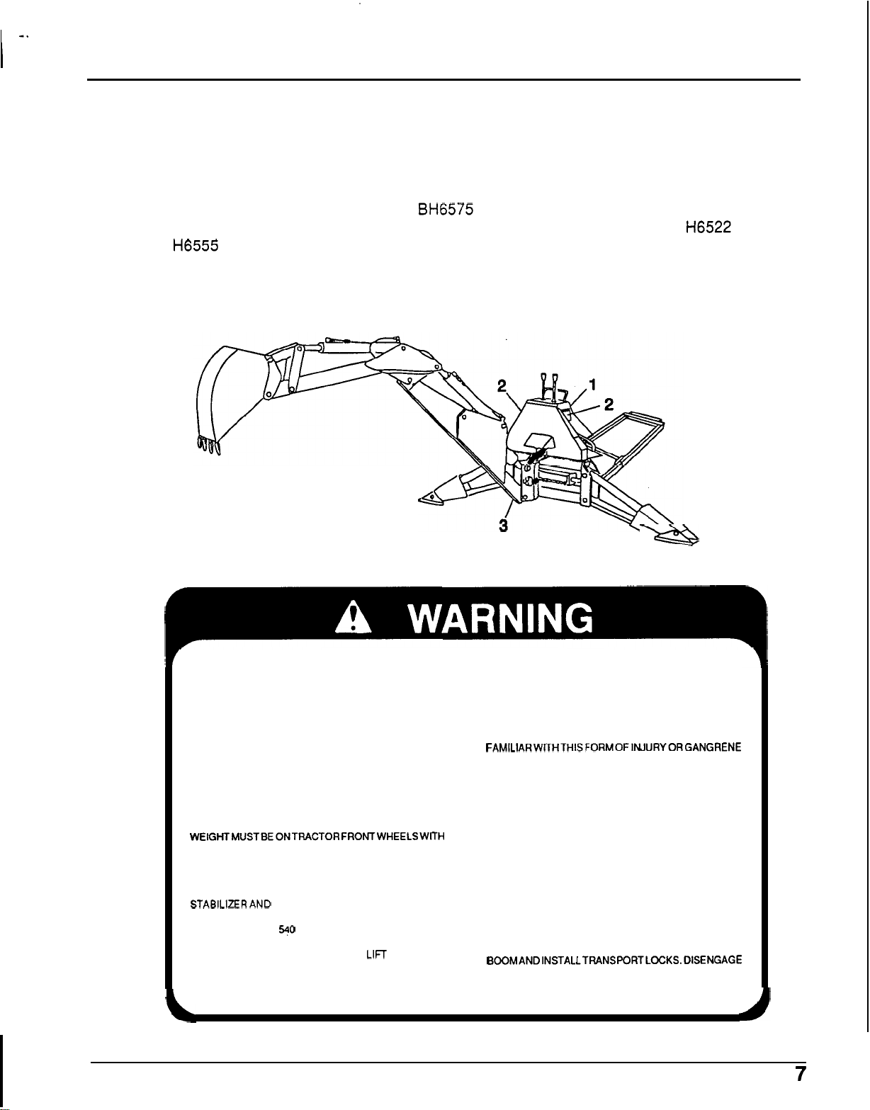
Nomenclature for backhoe components have
some variations throughout the industry. We use
SAE
shields
or
components removed.
designations as shown in Figure
other components removed
Operating the
or
any components removed
be
operated with any
backhoe
The
backhoe
2.
safety
2.
with
-
1.
Bucket
2.
Bucket cylinder
3.
Dipperstick cylinder
4.
Boom cylinder
5.
Console
6.
Stabilizer
Figure
2.
Backhoe Nomenclature
10.
11.
12.
13.
7.
Swing cylinder
8.
Boom
9.
Dipperstick
Stabilizer cylinder
Swing Frame
Main Frame
Sub-frame assembly
6
I
-*
SAFETY
SAFETY
,
SAFETY LABEL LOCATIONS
(Figure
Read all safety instructions before operating the BH6575 Backhoe. Anyone who uses the backhoe
should read and understand this information before operating the backhoe. Refer to the
Manual and
operating the backhoe.
The safety labels should be considered as permanent parts of the backhoe.
or becomes hard to read, contact an authorized Honda compact tractor dealer for replacements.
3)
H6555 Front Loader Operator’s Manual
1.
Warning Label
2.
Danger Label
3.
Lock
Label
Figure
3.
Safety Label Locations
H6522 Owner’s
for
additional safety label information before
If
a safety label comes
a
off
1
TO
AVOID
READ OPERATOR’S MANUAL AND FOLLOW ALL
SAFETY, OPERATING AND SERVICE INSTRUCTIONS
(CONTACT DEALER FOR MANUAL.) PENETRATES THE SKIN,
ENSURE
INSTALLED AND IN GOOD CONDITION.
DO NOT ALLOW CHILDREN
PERSONSTOOPERATE EQUIPMENT.
A MINIMUM
WEIGHTMUSTBEONTRACTORFRONTWHEELSWITH
BACKHOE IN TRANSPORT POSITION. NO RIDERS ARE ALLOWED ON TRACTOR
WHEN OPERATING, ALWAYS SIT IN BACKHOE SEAT;
KEEP BYSTANDERS AWAY FROM OPERATOR, BEFORE TRANSPORTING, ATTACH SLOW MOVING
STABILERAND MAXIMUM BUCKET SWING AREAS. VEHICLE (SMV) SIGN AND ENGAGE TRANSPORT
OPERATE PTO AT
BACKHOE DIGGING FORCES CAN
TRACTOR OVER. MAKE SURE STABILIZER PADS ARE
ON FIRM GROUND AND AVOID
BANKS.
ALL
SAFETY SHIELDS AND DECALS ARE
OR
25%
OF TRACTOR AND EQUIPMENT
540
RPM
MAX.
SERIOUS
UNQUALIFIED
LIFT AND TURN
SOFT
OR
STEEP
INJURY
OR
DEATH,
KEEP HANDS AND BODY AWAY FROM
HIGH
-
PRESSURE LINES. IF OIL, UNDER PRESSURE,
IT
MUST BE SURGICALLY
REMOVED WITHIN A FEW HOURS BY A DOCTOR
FAMlLlARWITHTHISFORMOFlNJURYORGANGRENE
MAY RESULT.
CONSULT LOCAL UTILITIES BEFORE DIGGING. KNOW
LOCATION OF AND AVOID CONTACTING ALL
UNDERGROUND CABLES, PIPELINES, OVERHEAD
WIRES AND OTHER HAZARDS IN DIGGING AREA.
BACKHOE.
LOCKS.
BEFORE LEAVING EQUIPMENT UNATTENDED. RAISE
BOOMANDlNSTALLTRANSPORTLOCKS.0lSENGAGE
PTO, RELIEVE PRESSURE ON DIPPERSTICK AND
BUCKET. SHUT ENGINE OFF AND REMOVE KEY.
OR

2
I
151
FULURE
TO
DEATH
FROM MCKHOE BEING THRUST UPWARD. FORWARD
BYWINOFORCES.
I
H
ONLY OPERATE WHEN MANUFACTURERS SUBFRAME AND FRONT-END
LOADER HAVE BEEN INSTALLED AND AWUSTED. AND
(SHOWN SHADED1
I
THESUTTOAPOlNT((rBEHlNDTHESUT
H
NEVER MOUNT BACKHOE TO
HITCH
I
CRUSHING
RXLOW THESE
IS
FREE FROM OBSTRUCTIONS IN
WILL
ROTATE
AND CAUSE
STEPS
YAY
A
TRACTOR
SERIOUS
HAZARD
RESULT
IN
SERIDUB
%POINT
HITCH.
INJURY
OR
INJURY
OR
REARWARD
OPEIUTOWS
A
UT
RAMUS
THE
DEATH.
9
OR
AREA
FROM
POINT
SAFETY
.-
I
H
FOW
BACKHOE AND SUBFRAME OPERATORS MANUAL MOUNTING
INSTRUCTIONS. (CONTACT
H
WLY MOUNT BACKHOE AND SUBFRUIE
WADERS
AS
SPECIFIED
ONLY USE MANUFACTURERS HEAVY
HIGHSTRENGTH TOP
H
DONOTMODlMORSUBST~UTEANYPARTOF8*CKHOE.SUB.FRIMEOR
MOUNTING
I
HARDWARE.
UNK
A
IN
MANUAL
PIN.
HONM
DEALER
K)R
MANUAL)
TO
TRACTORS
-
DUTY TOP LINK AND
WmC FRONT
8

I
-
SAFETY
SAFETY INFORMATION
Safety is a primary concern in the design and
manufacture of our products. Unfortunately, our
to
efforts
a single careless act of an operator.
In addition to the design and configuration of
equipment, hazard control and accident prevention
are dependent upon the awareness, concern,
prudence and proper training of personnel involved
in the operation, transport, maintenance and
storage
The best safety device is an informed, careful
operator. We ask you to be that kind of an operator.
The designed and tested safety of this equipment
depends on
as explained in this manual.
provide safe equipment can be erased by
of
equipment.
it
being operated within the limitations
TRAINING
Safety instructions are important! Read this
all
manual, the tractor manual and
rules.
0
Know your controls and how to stop tractor
engine and backhoe quickly in an
emergency.
0
Operators must be instructed in and
capable of the safe operation of the
equipment, its attachments and all
Do
controls.
thisequipmentwithout proper instructions.
0
Keep hands and body away from
pressurized lines. Use paper
not body parts to check for leaks. Hydraulic
fluid (oil) under pressure will penetrate skin
causing serious injury.
0
Make sure that
personnel know that in the event hydraulic
fluid penetrates skin,
removed within a few hours by a doctor
familiar with this form of injury, or gangrene
may result.
0
Do not allow children or unqualified
persons to operate equipment.
not allow anyone to operate
or
ail
operating and service
It must be surgically
safety
be
cardboard,
PREPARATION
0
The BH6575 Backhoe should only be used
with the Honda
Compact Tractor.
0
Always wear relatively tight and belted
clothing to avoid entanglement in moving
parts. Wear sturdy, rough
shoes and protective equipment for eyes,
hands, hearing and head.
0
Never operate unless backhoe’s sub-frame
has been installed and properly mounted to
a
Honda H6522
equipped with a
Do not operate backhoe unless there
adequate operator clearance as shown on
safety label. (Refer to Danger Label on page
8.)
0
Always use special heavy-duty top link
(provided with backhoe) and original
equipment high
(provided with tractor) to mount top link to
tractor. Use pin provided with backhoe to
mount top link to backhoe.
Ensure that backhoe is properly mounted,
adjusted and in good operating condition.
0
Ensure
good condition. (See page
Ensure shields and guards are properly
installed and in good condition.
0
A
weight must be on tractor front wheels with
backhoe in transport position. Without this
weight, the tractor could tip over causing
personal Injury or death. The weight must
be attained with a
fluid
wheel weights depending on the type of
rear tire.
Ag tires
tire and 75 Ib
rear wheel.
Turf or High Flotation Tires
ballast
all
safety labels are installed and in
minimum 25% of tractor and equipment
In
the rear wheels and possibly rear
-
99
in
each rear tire.
H6522
FL6555 Front Loader.
-
Ib (45 kg) ballast
(31.8
A4
(4-wheel drive)
-
soled work
A4
Compact Tractor
strength top link pin
7
illustrations.)
FL6555 Front Loader,
In
each rear
kg) wheel weight on each
-
170
Ib
(77
Is
kg)
Weigh the tractor and equipment.
estimate.
Do
not
9

0
Make sure that the hydraulic pump
spring activated locking pin slides freely
Is seated firmly in the tractor
and
spline groove.
0
Before working on backhoe, extend boom
and dipperstick and place bucket on
ground. Make sure that ail system pressure
has been relieved by operating controls
before maintenance, service or
disconnecting any hydraulic lines.
Hydraulic system
mechanical or hydraulic system can cause
equipment to drop.
0
Clean all dirt, trash and grease from
operator’s platform and steps.
leak down and failure of
OPERATIONAL SAFETY
0
Consult local utilities before digging. Know
location of and avoid contacting all
underground cables, pipelines, overhead
in
wires and other hazards
0
Keep bystanders away from operator,
stabilizer and maximum bucket swing
areas.
Operate only In daylight or good artificial
light.
0
When transporting, you must wear a seat
belt
if
your tractor
0
Always comply with all state and local
lighting and marking requirements.
0
No
riders are allowed on tractor or backhoe.
0
When Operating controls, always sit in
backhoe seat.
c]
Disengage Power Take
tractor into neutral or park, and place all
controls
engine.
0
Operate tractor
In
neutral before starting tractor
Is
equipped with a
PTO
at
digging area.
Off
(PTO),
540
rpm.
~~
PTO
PTO
ROPS.
shift
0
Be careful when swinging loaded bucket on
a hillside; always dump spoll on uphill side
of backhoe to
0
Always engage swing and boom transport
locks and attach Slow Moving Vehicle
(SMV)
0
Never leave equipment unattended with
engine running or with bucket
position. Always rest bucket on ground and
remove
0
Do
designed for digging.
sign before transporting backhoe.
Ignition key before leaving tractor.
not use backhoe for craning;
minimize upset possibility.
In
MAINTENANCE SAFETY
0
Always wear relatively tight and belted
clothing to avoid entanglement
parts. Wear sturdy, rough
shoes and protective equipment for eyes,
hands, hearing and head.
c]
Never perform service or maintenance with
tractor engine running.
Before working on backhoe, extend boom
and dipperstick and place bucket on
ground. Make sure that all system pressure
has been relieved by Operating controls
before maintenance, service or
disconnecting any hydraulic lines.
Hydraulic system leak down and failure
mechanical or hydraulic system can cause
equipment to drop.
0
Keep all persons away from operator
control area while
service or maintenance.
0
Tighten all bolts, nuts and screws, and
check that all cotter pins are Installed
securely to ensure backhoe
condition before operating.
0
Ensure all safety labels are installed and
good condition. (See page 7 Illustration.)
performing adjustments,
in
-
soled work
Is
In
raised
It
Is
moving
of
a safe
in
0
Always dump spoll at least
from opening.
0
Always provide a means to exit from trench
It
is
25
If
0
Use extreme care when working close to
fences, ditches or on hillsides.
feet or longer.
two
feet away
10
0
Ensure shields and guards are properly
installed and in good condition.
STORAGE
0
Refer to Removing and Storing Backhoe on
page
33.
ASSEMBLY INSTRUCTIONS
ASSEMBLY INSTRUCTIONS
.
..~..,<<
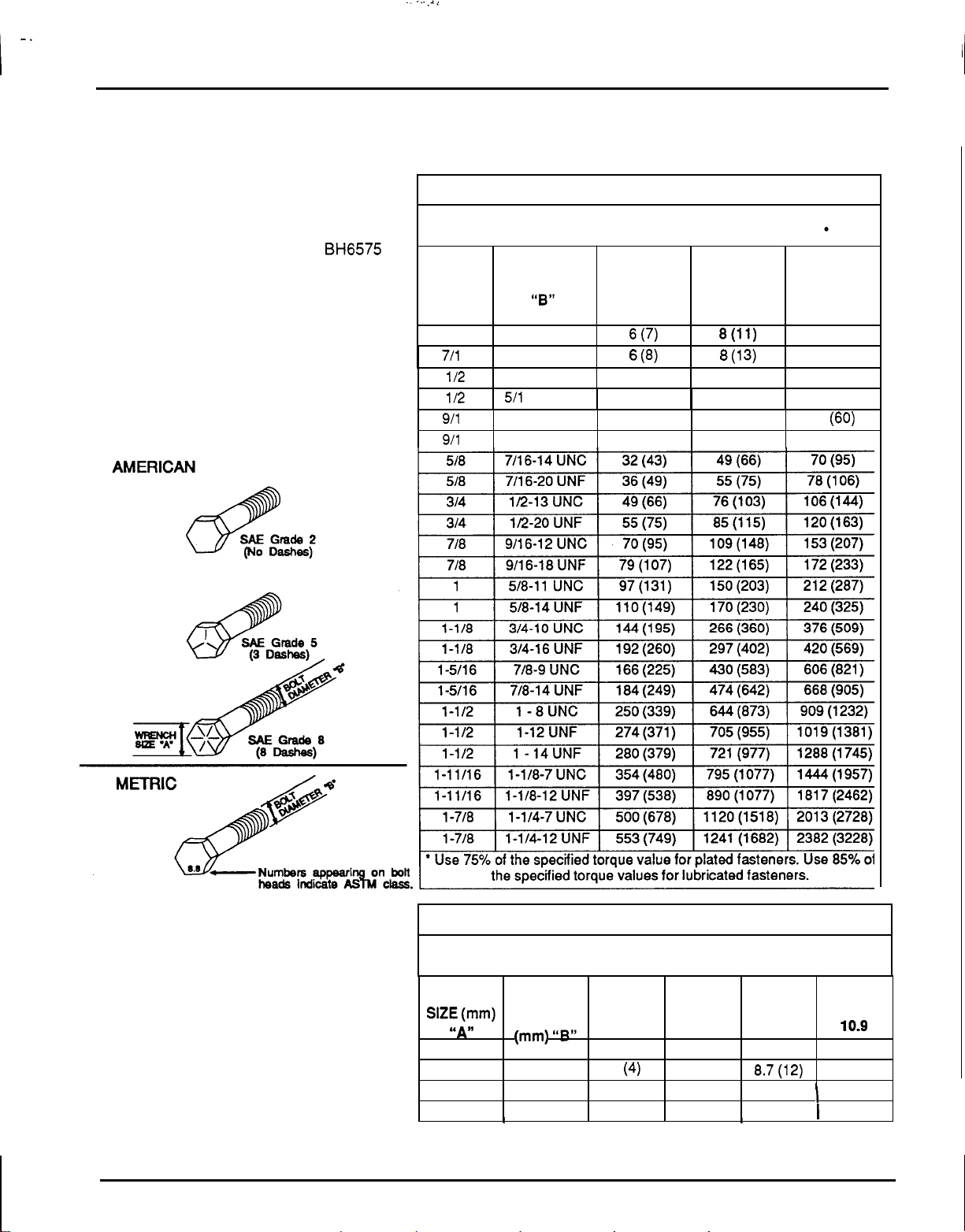
PROPER TORQUE FOR
FASTENERS
The chart lists
for fasteners used on the Honda
backhoe. When
replaced, refer to this chart
grade of
when specific torque values are assigned in
manual text.
Bolt
Head Markings
the
correct tightening torque
bolts
are
to
be tightened or
to
determine the
bolts
and the proper torque except
BH6575
TORQUE SPECIFICATIONS (AMERICAN)
Proper torque for American fasteners used on Honda equipment.
Recommended Torque in Foot Pounds (Newton Meters).
WRENCH
SIZE (IN.)
“A”
BOLT
DIAMETER
(IN.)
“8”
AND
GRADE
2
SAE SAE
GRADE
5
THREAD SIZE
6
1/4-20 UNC
1/4-28 UNF
5/16
-
18 UNC
511 6-24 UNF
3/8
-
20 UNC
3/8
-
24 UNF
6 (7)
(8)
11 (15)
20
(27)
23 (31)
8(11)
8
(1 3) 6
17 (23)
19 (26) 13 (1 7)
31 (42)
35 (47)
7/16
711 6
112
1/2
911 6
911
SAE
GRADE
12 (16)
14 (18)
25 (33)
27 (37)
44
(60)
49 (66)
8
TORQUE SPECIFICATIONS (METRIC)
Proper torque for Metric fasteners used on Honda equipment.
WRENCH
SlZE(mm)
‘SAW
8
12
14
I
Recommended Torque in
DIAMETER
(mm) UBlS
5
6 10
8
10
I
I I
4.6
1.8 (2.4)
3
(4)
7.3 (1
0)
Foot
Pounds (Newton Meter).
ASTM ASTM BOLT
CLASS CLASS
8.8
I
9.8
5.1 (6.9)
21.1 (29)
42 (57)
1
I
CLASS CLASS
6.5
11.1 (15) 8.7(12)
ASTM ASTM
10.9
27
53 (72) 14.5 (20)
(8.8)
(37)
I
11

ASSEMBLY INSTRUCTIONS
GENERAL ASSEMBLY
INSTRUCTIONS
Backhoe assembly is the responsibility of the
Honda Power Equipment Compact Tractor Dealer.
The backhoe should be delivered to the owner
completely assembled, lubricated and adjusted for
normal operating conditions.
Set up with these instructions and illustrations.
!
BA
assembly, complete the following check
Failure
serious injury
to
complete
When finished with
all
checklists could cause
or
death
to
the operator.
lists.
Pre-Deliveiy Check List
Inspect the backhoe thoroughly after assembly
be certain it is set up properly before delivering
to the customer. The check lists are a reminder of
off
points to inspect. Check
satisfactory or after proper adjustments are made.
Check all bolts to be sure they are tight.
c]
Check that all lubrication points have been
lubricated.
each item as it is found
to
Delivery Check List
c]
Show customer how to make adjustments.
c]
Explain importance
lubrication points to customer.
c]
Give Operator's Manual to customer and
recommend that all operators become familiar
with all sections and especially the safety
information.
Daily Check List
Check that the backhoe and .sub-frame are
properly and securely attached to the tractor
and front end loader sub
During inspection, check that all nuts and bolts
it
are secure and clevis pins are properly cotter
pinned.
0
Check for hydraulic leaks, frayed or worn hoses
and general safety of hydraulic system.
Instructions
for hydraulic leaks.
on
of
lubrication and show
Refer
page 9 and
-
frame.
to
the safety
10
before checking
c]
Check that all cotter pins and safety pins are
properly installed.
Check that the 'backhoe and sub-frame are
properly attached to tractor and front end
-
loader sub
c]
Check that
c]
Check that hydraulic reservoir has been
serviced and that hydraulic system and all
functions have been operated through full
cylinder stroke to purge air from system.
0
Make sure
there are no leaks in hydraulic system.
0
Refer to the safety instructions on pages 9 and
10
before checking for hydraulic leaks.
frame.
all
adjustments have been made.
all
hydraulic fittings are tight and
12

ASSEMBLY INSTRUCTIONS
DEALER SET
The backhoe is shipped partially assembled.
Assembly will be easier
and loosely assembled before tightening
hardware.
Recommended torque values for hardware are
given on page
vr
belted clothing to avoid entanglement in
and
moving parts. Wear sturdy, rough
shoes and protective equipment for eyes,
hands, hearing and head.
-
operator control area while performing
adjustments, service or maintenance.
from pressurized lines. Use paper or
cardboard, not body parts to check for
Hydraulic fluid (oil) under pressure will
penetrate skin causing serious Injury.
I
-
e
-
UP INSTRUCTIONS
if
components are aligned
11.
Always wear relatively tight
-
soled work
Keep all persons away from
Keep hands and body away
leaks.
Make sure that all operating
and service personnel know that In the event
hydraulic fluid penetrates skin, it must be
surgically removed within a few hours by
doctor familiar with this form of injury, or
gangrene may result.
SHIPPING PALLET PREPARATION
1.
Position backhoe on pallet in an assembly
a
area. Support unit with
(3),
Figure
2.
Remove the seat assembly from the backhoe.
3.
Remove
from backhoe components. Set the following
components
Sub-frame assembly
cross member and upper link are
attached to the sub
Bucket
Right Stabilizer assembly
4,
to provide stability.
all
bands, tie straps
off
the pallet for installation later.
chain hoist from lift lug
and
steel wire
(set
plate assembly,
-
frame).
(2)
a
1.
Shipping bar
2.
Shipping bands
3.
Lift
lug
4.
Right
stabilizer
Figure
4.
Backhoe
3
5.
Bucket
6.
Sub-frame assembly
7.
Seat assembly
8.
Shipping angles
in
Shipping Configuration
13

-
~ ~~~~
~~
Pallet Parts
1 Sub
1 Crossmember
1 Pin, 19 x 397.mm
1 Klik Pin, 1/4 x 1-3/4"
1 Upper Link
-
Frame
assy.
Assy.
Assy.
ASSEMBLY
Pivot Pin
1
\
Pivot Pins, 1
2
Clevis Pins, 1/4 x 1-718"
2
Clevis Pins, 1/16 x 1/2"
2
Control Handles
2
2
Grips (black)
Hex Lock Nuts,
2
Bolts,
2
Reducer w/O-ring, 1.31 x .88"
1
.O
x
7.25
"
1/2" NC
1/2NC X 1-1/2" HHCS
INSTRUCTIONS
WA
\
8
GR
5
1 Right Stabilizer
1 Bucket
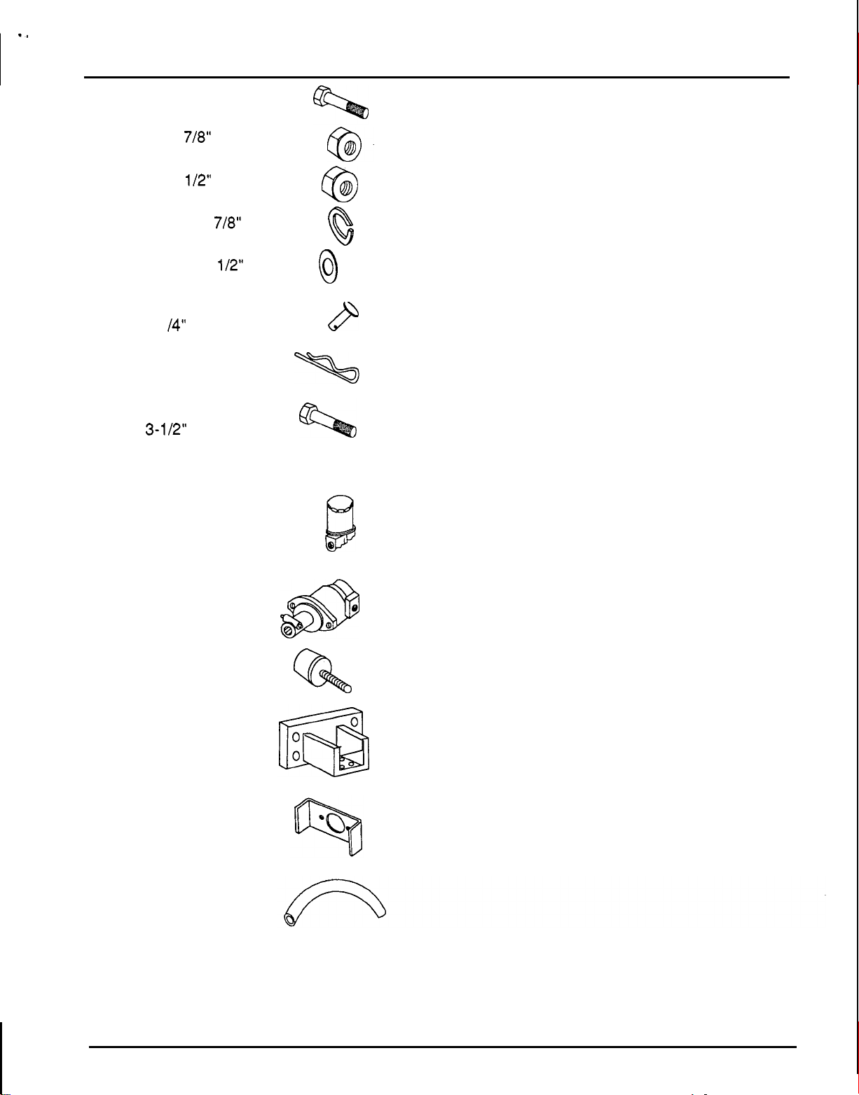
4. Open the parts box and lay parts out to make
location easy. Refer to parts list and the
illustrations below.
14
"
x
18
"
1 Breather Cap/dipstick
1 Elbow, 314 Hose 90'
1 Elbow, 7/8"-14 x 9/16"-18 90'
1 Fitting, 90'
Assy.
Double
Burlap Bag
Reducer O-ring Boss
1
Pivot Pins Retaining Sleeve
2
x
Spiral Pins, 5/16
2
Swing Lock Pin
1
Safety Pin,
1
3/16"
1 -3/4"
Burlap Bag
2 4-hole Backing Plates
-
hole Backing Plates
2 2
4 Bolts, 7/8 X 2-1/2" NC GR
8 Bolts, 1/2 X 1-3/4" NC
0
@
Q
\
5
2 Screw Hose Clamps
1
.OO"
1 Pin,
1 Pivot Pin (boom)
x 6.19" HT
14
8 Bolts, 1/2
4 Bolts, 12
4 Bolts, 12
X
1-1/2" NC
x
80 mm
x
1.25P x 35 mm
-,
.
ASSEMBLY INSTRUCTIONS
4
Bolts, 1/2 x 2" NC
4
Lock Nuts,
7/8"
NC
63
8
Lock Nuts, 1/2" NC
63
4 Lock Washers,
7/8"
Q
32 Flat Washers, 1/2"
1 High strength Clevis Pin,
3/4
X
3-1
14"
1 Safety Pin, 3/16
1 Backhoe Top Link Bolt,
X
3-1/2" NC
3/4
"
GR5
0
P
\
Loose
1 Oil Filter Assy.
1
2
2
1 Pump Mounting
Parts
box)
(in
Pump Assy.
Bumper Pads
Crossmember
Mounting Brackets
Bracket
(Box)
Q
1 Hose, 3/4
ID
x
40
"
15

ASSEMBLY
INSTRUCTIONS
Control Handle Installation
(Figure
1.
Install both control handles.
2.
Slide a rubber grip over each control handle.
5)
Stabilizer Installation (Figure
Right stabilizer (reference
BH6575
1.
2.
backhoe is shipped banded.
Remove right stabilizer pin
stabilizer
Remove bolt
assemble cylinder rod end and pad to right
stabilizer.
(7).
(9)
from right stabilizer pad and
7,
Figure
5)
5)
(3)
and attach
on the
I
16
1.
Control handle
2. Rubber
3.
Right stabilizer pin
4.
Clevis pin
5.
Cotter pin
-
grip
Figure
6.
Stabilizer cylinder
7.
Stabilizer frame
8.
Stabilizer pad
9.
Stabilizer
10.
Stabilizer pad nut,
5.
Stabilizer Installation
bolt,
3/4
NC
314"
x
6
NC locknut

ASSEMBLY
INSTRUCTIONS
'5
1.
Boom
2.
Dipperstick
3.
Bucket
4.
Retaining
5.
5/16
6.
Rotating pivot pin
Bucket
(Figure
sleeve
x
1
-3/4"
Spiral pin
&
Dipperstick
6)
Installation
7.
8.
9.
10. 1/4
11. 1/1
12.
Figure
Bucket arm
1
x
7-1/2"
1 x 4-7/8
x
1
-7/8"
6
x
1/2"
Dipperstick cylinder
6.
Dipperstick & Bucket Assembly
1. Remove shipping bar and attaching hardware
(Figure
2.
Align dipperstick
with pivot pin
reference
(8).
1).
(2)
with boom (1). Join them
Line up the pivot pin hole with
4,
hole in pivot bushing and secure with clevis pin
0)
and cotter pin (1 1).
(1
3.
Disconnect bucket hydraulic cylinder base end
where it attaches to the
,dipperstick. Route
bucket cylinder hoses through dipperstick
8).
openings (1
twisted. Install pivot pin
clevis
pin
(1
Make sure hoses are not
(9A) and secure with
0)
and cotter pin
(1 1).
Pivot
Pivot
Clevis
Cotter
13.
Bumper pad
14.
1
x
6-1"'
Pivot
Bolt
hose
pin
routing
pin
pin
pin
pin
4.
Fasten the bucket rod end hose (orange mark)
15. 1/4"
16. 1/4
17.
18.
Flange locknut
x
3/4"
Hose
clamp
Hydraulic
with the clamp (17) on the right side of the
"
dipperstick as shown. Leave 16
of hose
toward the rod end fitting past the clamp. Snug
bolt
(16) and locknut (15) but do not torque
down. Fasten bucket base end hose (white
of
mark) with clamp on left side
"
leaving 16
of hose extending toward the base
the dipperstick,
end fitting past the clamp. Snug bolt (16) and
locknut (15) but do not torque down. When
backhoe is installed on tractor, operate
dipperstick through the entire range of
movement and check that hose length beyond
the clamp is sufficient. After completing check,
tighten both hose clamps.
(12)
Align dipperstick cylinder
5.
and install pivot pin
(9B). Line up pivot pin hole
with dipperstick
with hole in pivot bushing. Secure with clevis
pin (10) and cotter pin (1 1).

6.
Actuate swing control handle and move boom
and dipperstick to the centered position. Lower
dipperstickand align bucket and bucket arm (7)
(6).
and install rotating pivot pin
retaining sleeve (4) and spiral pin
bucket with dipperstick and secure with
retaining sleeve (4) and spiral pin
boom and dipperstick, resting bucket on
ground.
7.
Remove lifting lug
install pivot pin
hole with hole in pivot bushing. Secure with
clevis pin (1
8.
Install rotating pivot pins
retaining sleeves (4) and spiral pins
9.
Install bumper pads
0)
(3), Figure 4, from boom and
(14), Figure
and cotter pin (1 1).
(13)
6.
(6)
to kingpost as shown.
Plumbing Installation (Figure
Keep hands and body from pressurized lines. Use
or
paper
leaks.
cardboard, not body parts, to check for
Secure with
(5).
Align
(5).
Lower
Line up pivot pin
and secure with
(5).
7.)
Hydraulic oil under
pressure will penetrate the skin causing
serious injury.
Make sure that all operating and service
personnel know that
penetrates skin,
In the event hydraulic fluid
It
must be surgically removed
within a few hours by a doctor familiar with this
form of injury, or gangrene may result.
To prevent damage to the
hydraulic system:
ASSEMBLY
1. Apply Teflon tape to the reservoir filter fitting.
2.
Install filter base inlet port-to reservoir fitting.
Install elbow (4) in outlet port of filter base. Ideal
orientation of the filter is vertical; position filter
base to accommodate this location. The filter
may be moved to provide clearance when
attaching backhoe to tractor
Install filter in filter base.
To
3.
4. Check pump reducers and elbows for O
5.
6.
7.
8.
9.
10. When backhoe is attached to tractor, it may be
11.
properly install hydraulic fittings with
-
rings, completely loosen locknut, screw
O
fitting completely in, hold in position and tighten
two
locknut using
before installing them.
Install reducer (1 1) in pump suction port.
Install
Install reducer (13) into pump pressure port.
Install elbow (14) into reducer (13).
Attach one end of suction hose
at the filter and the other end to elbow (10) at
the pump and secure with hose clamps
Attach hose (1
necessary to reposition filter and hoses to
eliminate interference.
Service hydraulic reservoir by filling
mark on dipstick (approximately 5 to 5-1/2 US
gallons) with Dexron
mounted and operated, filling cylinders, it will
be necessary to add fluid to the reservoir.
90’
elbow (10) into reducer
wrenches.
5)
to elbow (1 4).
INSTRUCTIONS
if
necessary.
(1
1).
(6)
to elbow (4)
to
II
ATF. When backhoe
-
rings
(5).
“full”
is
Clean all fittings and use care to prevent
foreign
material from entering hydraulic
system.
Additional sealant such as pipe dope or
Teflon thread tape is not required on O
-
ring
fittings.
Teflon thread tape
Is
recommended for pipe
threads. Use care when applying to prevent
excess tape from entering hydraulic
system.
Make sure all hydraulic connections are
tight and all hydraulic
In
good condition before engaging the
lines
and hoses are
tractor PTO.
(1
types or grades.
Fill with clean oil.
Do
Using unsuitable hydraulic oil
can damage the hydraulic system.
not mix oil

ASSEMBLY
INSTRUCTIONS
1. Dipperstick and breather
2. Reservoir
3. Fitter and housing
4.3"' Hose x 3/4" pipe, 90' elbow
5.
Hose clamp
6. 3/4
x
36" Low-pressure hose
7.
Pump mounting plate
x
8. 1/2
1" Bo#
Figure
9. 1 -1/2" Locknut
10. 1-1/16 - 12 x 3/4" Hose, 90' elbow
11.1-5/8"-12x1-1/16-12Reducer
12. Pump
13.1-5/16 - 12
14.
7/8"
15.9/16 - 18 Flare 34" High-pressure hose assembly
7.
Pump Installation
x
7/8
-
14 Reducer
-
14 x 9/16 - 18 Flare Elbow
ASSEMBLY
~~~~~
3.
Install the threaded end of the upper link
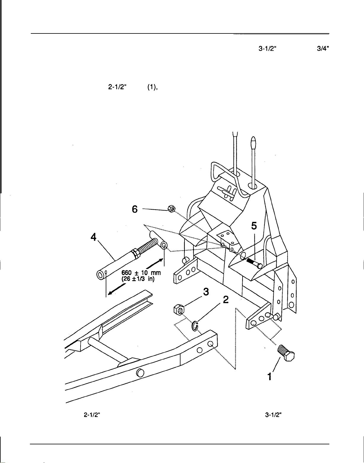
Sub-frame Installation (Figure
1.
Remove the hardware securing the backhoe to and adjust to the dimension shown for easier
8,
the pallet (reference
2.
Install the sub-frame to the backhoe as shown installation.
using the. four
washers
(2)
7/8
and nuts
Figure
x
2-1/2"
4).
bolts
(3).
Tighten to the
8)
(l),
lock
using the
locknut
3/4
NC
(6).
Loosen the threaded end jam nut
.installation during backhoe-to-tractor
INSTRUCTIONS
x
3-1/2"
bolt
(5)
and
specified torque.
A
(4)
3/4"
20
1.
718
2.718
X
2-112"
Bolt
"
Lockwasher
GR
5
3.
4.
Figure
718
"
nut
Top
link assembly
8.
Sub-frame
Installation
5.314
6.314
NC
X
"
Locknut
3-112" Bolt
GR
5

ASSEMBLY
4.
Remove and retain the four
(1)
bolts
to the transmission (Figure
INSTRUCTIONS
holding the
left
and right rolling pins
12
9).
x
75
The
mm flange
12
bolts and rolling pins must be retained for
-
point hitch installation.
3
x
75
(2)
mm
5.
Remove one of the
(3) and
shaft
(5)
1/2"
lock washer
to the
plates in place of the rolling pins
12
x
the four
washers
and
1/2"
80
(8).
Install the
lock washer
two
two
set plates
mm bolts
(4)
1/2
NC
x
1-1/4"
(4)
holding the cross
(6).
Install the set
as
shown with
(7)
and four
1/2
NC
x
1-1/4"
removed from the set
plate and tighten to the specified torque.
12
x
80
Tighten the
mm bolts (7) to the specified
torque.
6.
Remove the
rear PTO cover
two
6
x
(9).
12
mm
flange bolts and the
bolts
1/2"
bolt
flat
(3)
\
3
'4
1.12
x
75
mm
2.
Rear
Rolling Pin
3.
1/2 NC X 1-1/4"
4. 112"
5.
Lock
Cross
shaft
Figure
bolt
bolt
washer
9.
Set
(R)
Plate
GR
5
Assembly
6.
Set plate
7.12
x
80
8.
1/2"
Flat
9.
PTO
cover
Installation
(R)
mm
Bolt
washer
 Loading...