


Owner's Manual
Includes Remote Control
Supplement
Outboard Motor
BF9.9A/15A
©1990 Honda Motor Co., Ltd. — All Rights Reserved

.
The engine exhaust from this product
contains chemicals known to the State
defects or other reproductive harm.

Thank you for purchasing a Honda Outboard Motor.
This manual describes the operation and maintenance of the Honda
Outboard Motor: BF9.9AJ15A
All information in this publication is based on the latest product
information available at the time of printing.
Honda Motor Co., Ltd. reserves the right to make changes at any time
without notice and without incurring any obligation.
No part of this publication may be reproduced without written
permission.
This manual should be considered a permanent part of the Outboard
Motor and it must stay with the Outboard motor if resold.
READ THIS OWNER’S MANUAL CAREFULLY. Pay special attention to
these symbols and any instructions that follow.
m
You WILL be KlLLED or SERIOUSLY HURT if you don’t
follow instructions.
m
You CAN be KILLED or SERIOUSLY HURT if you don’t
follow instructions.
CAUTION:
pic?iEq
You CAN be HURT if you don’t follow instructions.
Your outboard motor or other property could be damaged if
you don’t follow instructions.
Honda Outboard Motors are designed to give safe and dependable
service if operated according to instructions. Operating this Outboard
Motor requires special effort on your part to ensure your safety and
the safety of others.
Careless operation or misuse may cause injury or property damage.
Read and understand this owner’s manual before operating the
Outboard Motor.
If a problem should arise, or if you have any .questions about your
Outboard Motor, see an authorized Honda Outboard Motor dealer.
Illustrations are mainly based on: BF15A LAS type
HONDA MOTOR CO., LTD. 1990, ALL RIGHTS RESERVED
1
CONTENTS
1. SAFETY
2. COMPONENT IDENTIFICATION
3. INSTALLATION
4. PRE-OPERATION CHECKS
5. STARTING THE ENGINE
6. OPERATION
0 High altitude operation
7. STOPPlNG,THE ENGINE
8. MAINTENANCE
9. TRANSPORTING/STORAGE
10. TROUBLESHOOTING
11. SPECIFICATIONS
12. WIRING DIAGRAM
13. OPTIONAL PARTS
14. WARRANTY SERVICE
..................................................................................................
.....................................................................................
.................................................................
....................................................................
........................................................................................
.................................................................
....................................................................
..................................................................................
..............................................................
.........................................................................
................................................................................
.............................................................................
...............................................................................
........................................................................
..........................................................
11
16
22
23
29
30
44
48
49
zi
54
3
5
7
2

1. SAFETY
I
Safety label locations
Read all safety instructions before using the Outboard Motor.
DANGER
IlAWFUL OS FATAL IF SIALLOVEO.
EL? OUT OF REACH OF CIIILOSEN.
IF SUAlLWEO.00 II01 IYOUCE
~CUtll16.CALl A PHYSICIAN
IUIEOIAYELY.
3
SAFETY INFORMATION
For your safety and the safety of others, pay special attention to these
precautions.
l Know how to stop the engine quickly in case of emergency.
Understand the use of all controls.
l Do not exceed the boat manufacturer’s power recommendation,
and be sure the outboard motor is properly mounted.
l Never permit anyone to operate the outboard motor without
proper instruction.
l Stop the engine immediately if anyone falls overboard.
l Do not run the motor while the boat is near anyone in the water.
l Attach the emergency stop switch lanyard securely to the operator.
l Before operating the outboard motor, familiarize yourself with all
laws and regulations relating to boating and the use of outboard
motors.
l Do not attempt to modify the outboard motor.
l Always wear a PERSONAL FLOTARON DEVlCE (PFD) when on
board.
l Exhaust contains poisonous carbon monoxide which can cause
unconsciousness and may lead to death. Never run the outboard in
a closed garage or confined area.
l Gasoline is.extremely flammable and is explosive under certain con-
ditions. Refuel in a well ventilated area with the engine stopped.
. Do not smoke or allow flames or sparks where the engine is
refueled or where gasoline is stored.
l Do not overfill the fuel tank. After refueling make sure that the fuel
tank cap is closed properly and securely.
l Be careful not to spill any fuel while refueling. Spilled fuel or fuel
vapor may ignite. lf any fuel is spilled make sure that the area is dry
before starting the engine.
l Do not remove any guards, labels, shields, covers or safety devices;
they are installed for your safety.
4

ENGINE COVER
WATER CHECK HOLE
ENGINE OIL DRAIN PLUG
2. COMPONENT IDENTIFICATION
STARTER GRIP
/
CY STOP SWlTCH
CLAMP SCREW
ANTI-VENWAlTlON PLATE
PRIMER BULB
FRAME SERIAL NUMBER
*Always list the serial number when
ordering parts.

THRO:::&
TILLER HANDLE
STERN BRACKET
Jz OIL LNEL DIPSTICK
ENGINE COVER LOCK LEifER
ADJUSTlNG ROD
GEAR OIL LEVEL PLUG
WATER INTAKE SCREEN
GEAR OIL DRAIN iLUG’
OIL PRESSURE INDICATOR UGHT
ENGINE STOP SWlTCH
CHOKE KNOB
WASHING BOLT
ANODE METAL
ZEllST AND DRAlNlNG
6
FUEL HOSE CONNECTORIMALE)

3. INSTALLATION
It is your responsibility to choose a boat suitable for the engine.
BF9.9A: 9.9 HP (7.4 kW)
BFlSA: 15 HP (11.2 kW1
N
Do not exceed the boat manufacturer’s power recommendatidn.
Damage and injury may result.
1. Installation position
Install at the stern, at the center
line of the boat.
2. Installation height
For proper ropeller depth and
engine coo ing, the boat and P
outboard motor transom height
must match. .
Three outboard motor transom
heights are available. Match
your boats transom height to the
outboard motor transom height
shown below.
MOTOR
EFM
STERN CEiTER
The anti-ventilation plate should
be O-50 mm (O-2 in) below the
bottom of the boat. With the
boat in the water, loaded and
motor off, the anti-ventilation
late should be about 100 mm
3.9 in) below the surface of the
P
water.
(J
Running the outboard motor
without sufficient cooling water
will damage the water pump
and overheat the engine.
mm
in)
7

3. Motor attachment
Attach the stern bracket to the
transom and tighten the clamp
screws.
[NoncEI
l Before operating the boat, check
the tightness of the clamp screws.
l Tie a rope through the hole in the
stern bracket and secure the
other end of the rope to the boat.
This will prevent accidental loss
of the motor.
SAFETY ROPE
NOTE:
To prevent the outboard motor from
falling accidentally, you may further
secure the stern bracket to the
transom board with commercially
available bolts, nuts and washers.
After attaching the stern bracket to
the transom board, be sure to apply
sealant (THREEBOND 1216 or equivalent) to the bolt holes.
This modification should be made
by your authorized Honda Outboard
Motor dealer.
,
a
STERN WASHER
WASHER TRANSOM BOARD
8
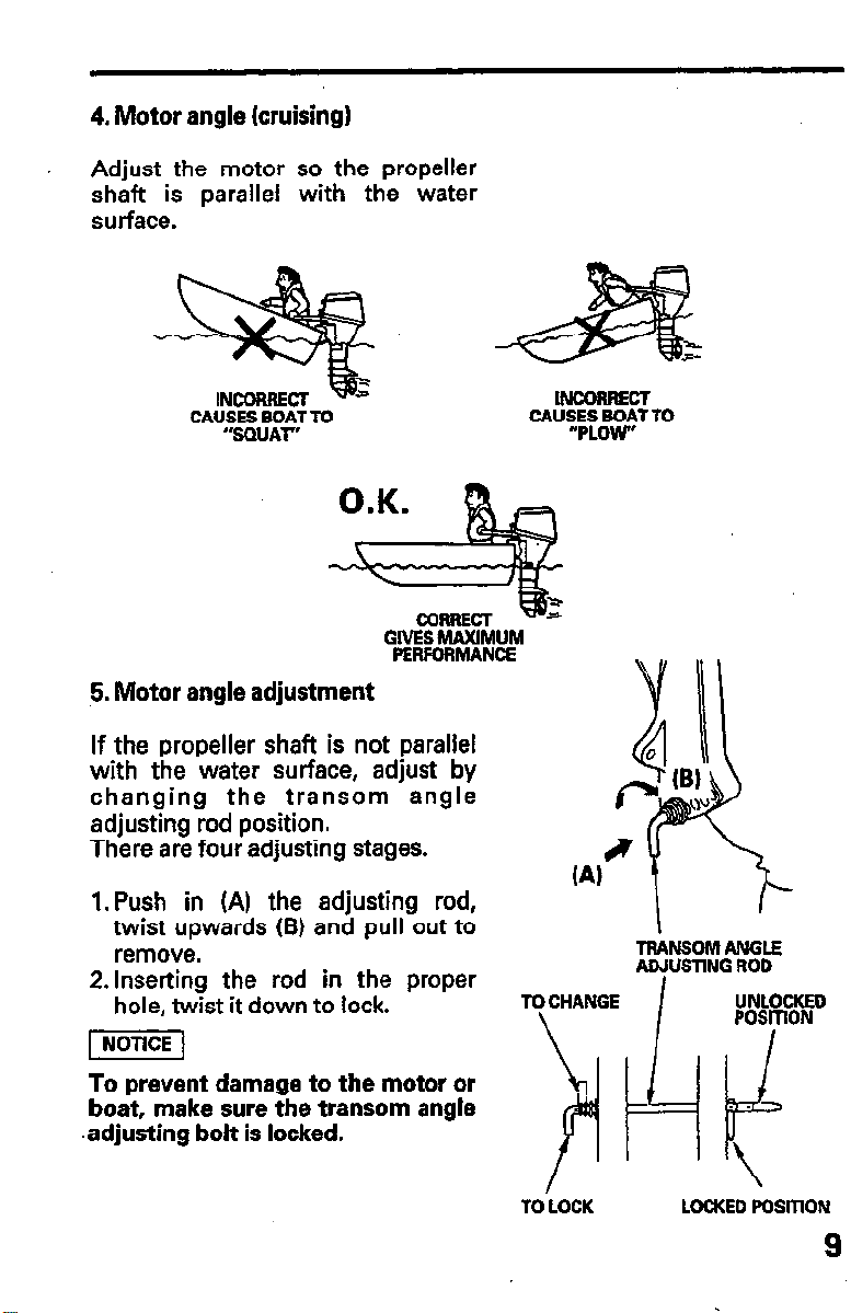
4. Motor angle (cruising)
Adjust the motor so the propeller
shaft is parallel with the water
surface.
CAUSES BOAT TO
“‘SQUAT”
GlVES MAXlMUM
PERFORMANCE
5. Motor angle adjustment
If the propeller shaft is not parallel
with the water surface, adjust by
changing the transom angle
adjusting rod position.
There are four adjusting stages.
1. Push in (A) the adjusting rod,
twist upwards (B) and pull out to
remove.
2. Inserting the rod in the proper
hole, twist it down to lock.
INCORRECT
CAU%fo~~T TO
TRANSOM ANGLE
ADJUSTlNG ROD
TO CHANGE UNLOCKED
pii5iq
To prevent damage to the motor or
boat, make sure the transom angle
.adjusting bolt is locked.
TO LOCK
LOCKED POSmON
9

6. Battery connections (for electric starter)
Use a 12V40AH battery.
Place the battery in a corrosion-resistant battery box and fix the
battery box securely to the hull.
Install the battery box in a location such that remains level while the
boat is cruising and is not exposed to spray or direct sunlight.
Connecting the battery cord
1. Connect the cable with the red terminal cover to the (+) side of the
battery.
2. Connect the cable with the black terminal cover to the (-1 side of the
battery.
(-)lERMINAL
l Be sure to connect the (+) side battery cable first. When
disconnecting the cables, disconnect the (- 1 side first then the (+ 1
side.
l Unless the cables are properly connected to the terminals, the
starter motor may fail to operate normally.
l Do not place the fuel tank near the battery.

1. Engine oil level
sevice
recommended,
engine
/iiGiq
l Engine oil is a major factor affecting engine performance and
life. Nondetergent and low quality oils are not
because they have inadequate lubricating properties.
l Running the engine with insufficient oil can cause serious
damage.
Use Honda 4-stroke oil, or an equiva-
lent high detergent, premium
quality motor oil certified to meet or
exceed U.S. automobile manufacturer’s requirements for Service
Classification SG, SF. Motor oils =~p
classified SG, SF will show this designation on the container.
SAE low/30 is recommended for general, all-temperature use. Other
viscosities shown in the chart may be used when the average
temperature in your area is within the indicated range.
1. Position the outboard motor vertically,and remove the engine cover
by pushing down the engine cover lock lever.
2. Remove the oil level dipstick and wipe with a clean rag.
3. Reinsert the dipstick all the way in, then pull it out and read the level.
If the oil level is down toward the lower level mark, fill to the upper
level mark.
Tighten the oil filler cap securely.
4. Install the engine cover and lock it securely by pulling up lock lever.
Oil capacity: 1 .l 8 (1.2 US qt , 1.0 Imp qt)

2. Fuel level
Fuel tank capacity: 12 8 (3.0 US gal, 2.6 Imp gal)
EL GAUGE
Check the fuel gauge and refill the tank to the SAFE FILL LEVEL mark if
necessary.
Gasoline is extremely flammable, and gasoline virpor can explode,
causing serious injury or death. Do not smoke or allow flames or
sparks in your working area. KEEP OUT OF REACH OF CHILDREN.
VENT KNOB
.
FUELC
Refilling
Remove the fuel tank from the boat for refilling. Turn the vent knob
counterclockwise to the open position and remove the fuel cap.
Refuel in a well-ventilated area. Fill the fuel tank up to the SAFE FILL
LEVEL mark only. Inspect the condition of the fuel cap gasket and
replace if necessary.
After refilling, install and tighten the fuel cap securely. Turn the vent
knob clockwise to the closed position. Return the fuel tank to the boat.
12

Fuel Recommendations
13
Use unleaded gasoline with a pump octane rating of 86 or higher.
This engine is desi ned to operate on unleaded gasoline. Unleaded
gasoline produces ewer engine and spark plug deposits and extends
9
. exhaust system life.
Never use stale or contaminated gasoline or an oil/gasoline mixture.
Avoid getting dirt or water in the fuel tank.
Occasionally
rapping noise while operating under heavy loads. T
ou may hear light “spark knock” or ”
Y
inging” (metallic
It
is IS no cause for
concern.
If spark knock or pin
normal load, than
persists, see an aut
ing occurs at a steady engine speed, under
13
e
rands of gasoline. If spark knock or pinging
1
orized Honda dealer.
Running the engine with persistent spark knock or pinging can cause
engine damage.
Running the engine with persistent spark knock or pinging is misuse,
and the Distributor’s Limited Warranty does not cover parts damaged
by misuse.

OXYGENATED FUELS
Some conventional asolines are being blended with alcohol or an
ether compound. T ese I! gasolines are collectively referred to as
oxygenated fuels. To meet clean air standards, some areas of the
United States and Canada use oxygenated fuels to help reduce
emissions.
If you use an oxygenated fuel, be sure it is unleaded and meets the
mmimum octane rating requirement.
Before using an oxygenated fuel, try to confirm the fuel’s contents.
Some states/provinces require this information to be posted on the
pump.
The following are the EPA approved percentages of oxygenates:
ETHANOL -
MTBE
(ethyl or grain alcohol) 10% by volume
You may use
by volume. 8
marketed under the name “Gas0
asoline containing up to 10% ethanol
asoline containin
ethanol may be
I!
01”.
(Methyl Tertiary Butyl Ether) 15% by volume
You may use gasohne containing up to 15% MTBE
by volume.
METHANOL -
(methyl or wood alcohol) 5% by volume
You may use gasoline containing up to 5%
methanol by volume, as long as it also contains
cosolvents and corrosion inhibitors to protect the
fuel system. Gasoline containing more than 5%
methanol by volume may cause starting and/or
performance problems. It may also damage metal,
rubber, and plastic parts of your fuel system.
If you notice any undesirable operating symptoms, try another service
station, or switch to another brand of gasoline.
Fuel system dama e or performance problems resulting from the use
of an oxygenate
CB
fuel containing more than the percentages of
oxygenates mentioned above are not covered under warranty.
14
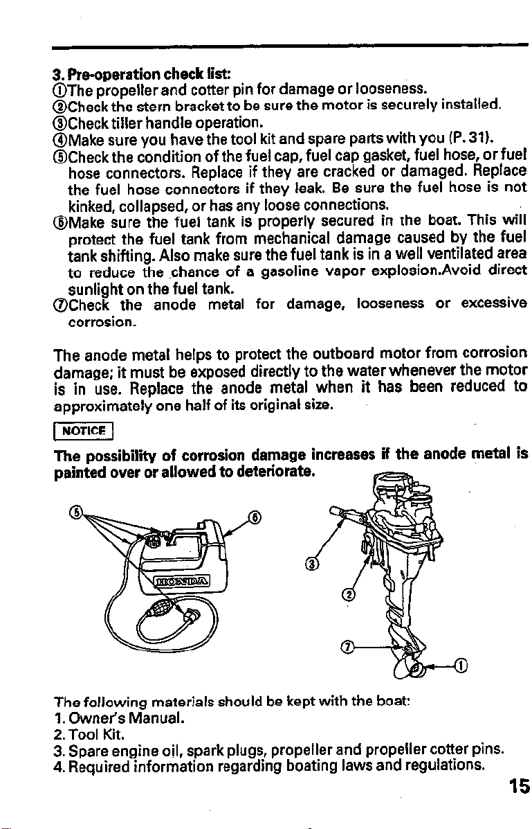
3. Pre-operation check list:
is
15
@The propeller and cotter pin for damage or looseness.
@Check the stern bracket to be sure the motor is securely installed.
@Check tiller handle operation.
@Make sure you have the tool kit and spare parts with you (P. 31).
@Check the condition of the fuel cap, fuel cap gasket, fuel hose, or fuel
hose connectors. Replace if they are cracked or damaged. Replace
the fuel hose connectors if they leak. Be sure the fuel hose is not
kinked, collapsed, or has any loose connections.
@Make sure the fuel tank is properly secured in the boat. This will
protect the fuel tank from mechanical damage caused by the fuel
tank shifting. Also make sure the fuel tank is in a well ventilated area
to reduce the .chance of a gasoline vapor explosion.Avoid direct
sunlight on the fuel tank.
@Check the anode metal for damage, looseness or excessive
corrosion.
The anode metal helps to protect the outboard motor from corrosion
damage; it must be exposed directly to the water whenever the motor
is in use. Replace the anode metal when it has been reduced to
approximately one half of its original size.
The possibility of corrosion damage increases if the anode
painted over or allowed to deteriorate.
The following materials should be kept with the boat:
1. Owner’s Manual.
2. Tool Kit.
3. Spare engine oil, spark plugs, propeller and propeller cotter pins.
4. Required information regarding boating laws and regulations.
metal

5. STARTING THE ENGINE
Fuel line connection
Check the fuel tank related components and fuel tank positioning
(refer step @ and @ on page 15 1.
Due to the fuel pump capacity, do not place the fuel tank more than 6
feet away from the motor or lower than 3 feet below the outboard end
fuel hose connector.
Be careful not to spill any fuel while refueling. Spilled fuel or fuel
vapor may ignite. lf any fuel is spilled make sure that the area is dry
before starting the engine.
1iConnect the fuel hose connectors to the outboard motor and fuel
tank as shown. The outboard end fuel hose connector must be
installed with the clip toward the outside or the fuel hose connector
O-ring seal can be damaged. Replace the fuel hose connectors if
they leak. Check to be sure that both connectors are securely
snapped in place.
(OUTBOARD END) (FUEL TANK END)
FUEL HOSE CONNECTOR
FUEL HOSE
CONNECTOR
If the outboard end fuel hose connector is installed in the reversed
direction, the fuel hose connector O-ring seal can be damaged.’ A
damaged O-ring seal can cause a fuel leak.
2. Open the fuel cap vent knob 2 to 3 turns.
3.Hold the primer bulb so that the outlet end is higher than the inlet,
and squeeze it until it feels firm, indicating that fuel has reached the
motor. Check for leaks.
NOTE:
Do not squeeze the primer bulb when the motor is running because
this could cause the carburetors to overflow.
PRIMER SU
16

Starting
cause
17
Exhaust contains poisonous carbon monoxide which can
unconsciousness and may lead to death. Never run the outboard in a
closed garage or confined area.
The anti-ventilation plate must be lowered into the water and be at
least 2 inches below the surface. Running the outboard motor out of
the water will damage the water pump and overheat the engine.
1. Engage the emergency stop switch clip located at one end of the
emergency stop switch lanyard with the engine stop switch. Attach
the other end of the emergency stop switch lanyard securely to the
operator.
If the operator does not attach the emergency stop switch lanyard,
and is thrown from his seat or out of the boat, the out-of-control boat
can seriously injure the operator, passengers, or bystanders. Always
r;frly attach the lanyard before starting the motor.
.
.
l The engine will not start unless the emergency stop switch clip is
engaged with the engine stop switch.
l A spare emergency stop switch
ENGINE STOP
clip is provided in the tool bag.
fPWAREEIE$GENCY STOP
2. Put the gearshift lever in NEUTRAL.
NEUTRAL
EARSHIFT LEVER
EMERGENCY STOP
SWlTCH LANYARD

3.Align the throttle grip START position with the mark on the tiller
handle.
THR0lTl.E GRIP
4. If the engine is “cold”, pull out the choke knob for starting and then
push it in gradually as the engine warms up.
CHOKE KNOB
5. Pull the starter rope slowly until a resistance is felt, then pull briskly.
piiEq
l Do not allow the starter grip to snap back against the engine.
Return it gently to prevent damage to the starter.
l Do not pull the starter grip while the engine is running, as that may
damage the starter.
STARER GRIP
18

6. Electric starter (Electric starter model only)
Put the outboard motor in NEUTRAL, then press the electric starter
button and start the engine.
ELECTRIC STARTER BUllON
-
l Do not use the starter motor for more than 5 seconds. lf the engine
fails to start, release the key, and wait at least 10 seconds before
operating the starter motor again.
l Do not press the electric starter button while the engine is running.
. This may damage the starting unit.
NOTE:
If the engine fails to start, check the emergency stop switch clip.
7.The oil pressure indicator light should be ON while the engine is
running. If the light goes off, stop the engine immediately, check the
engine oil level and inspect engine for oil leaks.
NOTE:
If the oil level is OK, but the light stays off while the engine is running,
take the motor to an authorized Honda Outboard dealer immediately.
OIL PRESSURE INMCATOR UGHT
19

8. After starting, be sure water is flowing out of the water check hole.
If water does not flow out, or if steam comes out, stop the engine.
Check to see if the screen in the cooling water inlet is obstructed. Do
not operate the engine until the problem has been corrected.
9. If the choke was used, push it in gradually as the engine warms up.
NOTE:
Before leaving the dock, check the operation of the emergency stop
switch.
20

Emergency stating
If the recoil starter is not working properly, the engine can be started
with the spare starter rope in the tool kit.
1. Remove the engine cover.
6MM BOLT6
2. Remove the recoil starter by removing the three 6 mm bolts.
3. Disconnect the neutral starter
cable.
4. Wind the spare rope clockwise
around the pulley, and then pull it
straight out to start the engine.
c 1
Keep clear of moving pa-.
5. Leave the recoil starter off and
reinstall engine cover.
Exposed moving parts can cause
injury. Use extreme care when
installing the engine cover. Do not
operate the outboard motor
Without the engine cover.
STARTER CABLE
STARTER ROPE
21

6. OPERATION
r
For the first 10 hours of operation, run the outboard motor at low
speed, and avoid abrupt operation of the throttle.
1. Gear shifting
Put the tilt lever in the RUN position to prevent the outboard motor
from tilting up, when operating in reverse (refer to page 25 1.
The gearshift lever has 3 positions : FORWARD, NEUTRAL, and
REVERSE. An indicator at the base of the gearshift lever aligns with
letters F, N, or R on the engine case to show the gear that has been
selected.
Turn the throttle grip to SHIFT to decrease engine speed before
moving the gearshift lever.
p?iEq
When operating in reverse, proceed with caution to avoid hitting any
underwater obstructions with the propeller.
NOTE:
The throttle mechanism is designed to limit throttle opening in
REVERSE and NEUTRAL. The throttle can be opened to FAST only in
FORWARD gear.
THROTILE GRIP
NEUTRAL
22

2. Steering
To turn to the right, swing the tiller handle to the left. To turn to the left,
swing the tiller handle to the right.
Boats equipped with a remote control steering wheel are controlled in
the same way as a car.
RIGHT TURN
LEFTTURN
Swing the tiller handle to the left.
Swing the tiller hendle to the right.
The steering friction should be adjusted so that stable boat operation
is maintained with a minimum of operator effort.
STEERING
FRICTION BOLT
23

3. Cruising
With the gearshift lever in the
forward position F, turn the throttle
grip toward FAST to increase speed.
For normal cruising, open the
throttle about 3/4.
To hold the throttle at a steady
setting, turn the throttle. friction
knob clockwise. To free the throttle
grip for manual speed control, turn
the friction knob counterclockwise.
NOTE:
This outboard motor is provided
with an over-rev limiter in order to
prevent a breakdown due to
excessive engine speed. Depending
upon the running condition of the
outboard motor (if the force applied
to the propeller is light, for example),
the limiter may operate, causing the
engine speed to become unstable,
thus preventing stable running. If
the engine speed becomes unstable
when the outboard motor is run
with the grip near the “fully open”
position, return the grip to the “low
speed”
side until the speed
becomes stable.
1NoTlCEJ
GEARSHIFT LEVER
THROTTLE GRIP
l Do not operate without the
engine cover. Exposed moving
parts could cause injury; water
may damage the engine.
l Confirm that the tilt lever is in the
“RUN” position (page 25 I.
l For best performance, passengers
and equipment should be
distributed evenly to balance the
boat.
24
 Loading...