

Honda BF25 А, BF30 А Owner's Manual
HONDA
mmRinE
BF25Al3OA
Owner's
Manual
@
2001
Honda Motor
Co.,
Ltd.
-All
Rights
Reserved
2002
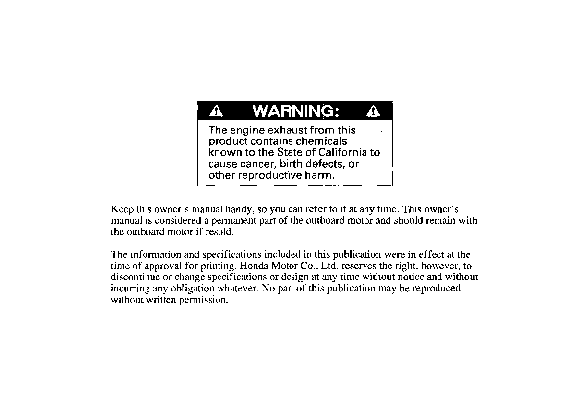
The engine exhaust from this
product contains chemicals
known to the State of California to
cause cancer, birth defects, or
other reproductive harm.
Keep this owner’s manual handy,
manual is considered a permanent part of the outboard motor and should remain with
the outboard motor
The information and specifications included
time of approval for printing. Honda
discontinue
incurring any obligation whatever.
without written permission.
or
if
resold.
change specifications or design at any time without notice and without
so
you can refer to it at any time. This owner’s
in
this publication were in effect at the
Motor
Co.,
Ltd. reserves the right, however, to
No
part of this publication may be reproduced
INTRODUCTION
Congratulations on your selection of
a Honda outboard motor. We are
certain you will be pleased with your
purchase of one of the finest
outboard motors on the market.
We want to help you get the best
results from your new outboard
motor and to operate
manual contains the information on
how to do that; please read
carefully.
As
you read this manual you will
find information preceded by a
symbol. That information
is intended to help you avoid damage
to your outboard motor, other
property, or the environment.
it
safely. This
it
We suggest you read the warranty
policy to fully understand its
coverage and your responsibilities of
ownership. The warranty policy is a
separate document that should have
been given to you by your dealer.
When your outboard motor needs
scheduled maintenance, keep in mind
that your Honda marine dealer is
specially trained in servicing Honda
outboard motors. Your Honda marine
dealer is dedicated
satisfaction and will be pleased to
answer your questions and concerns.
0
2001
Honda Motor
Rights Reserved
to your
Co.,
Ltd.
All
1
INTRODUCTION
A
FEW
SAFETY
Your safety and the safety of others
are very important. And using this
outboard motor safely is an important
responsibility.
To help you make informed
decisions about safety, we have
provided operating procedures and
other information on labels and in
this manual. This information alerts
you to potential hazards that could
hurt you or others.
Of course,
possible to warn you about all the
hazards associated with operating or
maintaining an outboard motor. You
must use your own good judgment.
WORDS
it
is not practical or
ABOUT
a
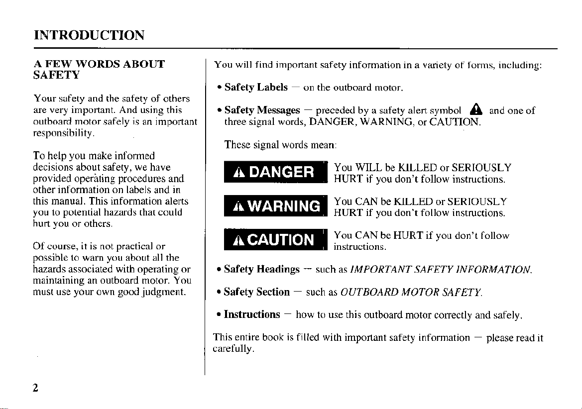
You will find important safety information in
Safety Labels
Safety Messages
-
on the outboard motor.
-
preceded by a safety alert symbol A and one of
variety of forms, including:
three signal words, DANGER, WARNING, or CAUTION.
These signal words mean:
You WILL be KILLED or SERIOUSLY
HURT if you don’t follow instructions.
You CAN be KILLED or SERIOUSLY
HURT if you don’t follow instructions.
You CAN be HURT if you don’t follow
instructions.
Safety Headings
Safety Section
-
such as IMPORTANT SAFETY INFORMATION.
-
such as OUTBOARD MOTOR SAFETY.
2
Instructions
This entire book
carefully.
-
how to use this outboard motor correctly and safely.
is
filled with important safety information - please read it
CONTENTS
OUTBOARD MOTOR SAFETY
IMPORTANT SAFETY INFORMATION
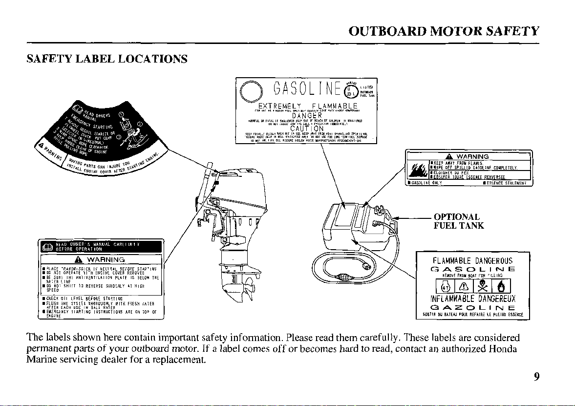
SAFETY LABEL LOCATIONS .................................
CONTROLS AND FEATURES
CONTROL AND FEATURE
IDENTIFICATION CODES
COMPONENT AND CONTROL LOCATIONS ..... 11
CONTROLS
H
Type
Engine Stop Switch and Switch Clip
Choke Knob
Throttle Grip
Throttle Friction Knob
Gearshift Lever
Recoil Starter Grip
Electric Starter Button
R Type
Ignition Switch
Switch Clip and Emergency Stop Switch
Choke/Fast Idle Lever
............................................................... I4
........................................................................
........................................................... 14
........................................................... 15
......................................................
.................................................
........................................................................
....................................................... 16
....................................
.................
...................................
.................................
.....................
...........................................
............................................
..............
............................................ 18
7
7
9
10
10
14
14
15
15
16
16
16
17
GearshiftIThrottle Control Lever ...........................
Manual Choke Knob
Common Controls
Engine Cover Latch
Transom Angle Adjusting Rod
Trim Tab
Steering Friction Bolt ............................................. 21
Tilt Lever
INSTRUMENTS
Fuel Gauge
INDICATORS
Oil Pressure Indicator
Overheating Indicator
Cooling System Indicator
OTHER
Overrev Limiter
Anode
Portable Fuel Tank
Fuel Cap Vent Knob
Fuel Priming Bulb
.................................................................
................................................................ 22
............................................................. 22
............................................................
FEATURES
..................................................................... 24
..............................................
......................................................
............................................... 20
.............................. 20
........................................................ 22
.............................................
............................................
......................................
.................................................
......................................................
................................................. 24
.............................................. 25
..................................................
18
20
20
21
22
22
23
23
24
24
25
3
CONTENTS
INSTALLATION
POWER REQUIREMENTS
BOAT TRANSOM REQUIREMENTS
INSTALLATION POSITION
ATTACHMENT
TRANSOM ANGLE ADJUSTMENT
BATTERY CONNECTIONS
BEFORE OPERATION
ARE YOU READY TO GET UNDER WAY? ...... 31
IS YOUR OUTBOARD MOTOR
READY TO GO
OPERATION
SAFE OPERATING PRECAUTIONS
BREAK-IN PROCEDURE
TRANSOM ANGLE ADJUSTMENT
PORTABLE FUEL TANK
FUEL HOSE CONNECTIONS
FUEL PRIMING
...........................................................
......................................
....................
...................................
........................................................
......................
....................................
.................................................
?
.................................................
.................................................................
.....................
........................................
......................
........................................
.................................
........................................................
26
26
26
26
27
28
28
3
31
33
33
33
34
35
35
36
STARTING THE ENGINE
H
Type
....................................................................
R
Type
....................................................................
EMERGENCY STARTING
STOPPING THE ENGINE
Emergency Engine Stopping
Normal Engine Stopping 44
GEARSHIFTING AND
1
THROTTLE OPERATION
H Type
R Type
STEERING
H Type
R Type
CRUISING
SHALLOW WATER OPERATIONS
MOORING, BEACHING, LAUNCHING
....................................................................
....................................................................
................................................................
....................................................................
....................................................................
.................................................................
....................................... 36
36
39
......................................
41
........................................ 44
................................. 44
........................................
...............................
.......................
................
46
46
47
48
48
48
49
50
51
4
CONTENTS
SERVICING YOUR OUTBOARD MOTOR ............... 52
THE IMPORTANCE OF MAINTENANCE
MAINTENANCE SAFETY
TOOL KIT AND EMERGENCY STARTER
ROPE
......................................................................
MAINTENANCE SCHEDULE
TRIM TAB ADJUSTMENT
ENGINE COVER REMOVAL AND
INSTALLATION
Engine Oil Level Check
Engine Oil Change
Engine Oil Recommendations
Gear Oil Level Check
Gear Oil Change
Lubrication Points
Spark Plug Service
REFUELING
FUEL RECOMMENDATIONS
Fuel Pump Filter Inspection and Replacement .......... 68
Portable Fuel Tank and Filter Cleaning
Recoil Starter Rope Inspection
Anode Replacement
Propeller Replacement
...................................................
.....................................................
.........................................................
......................................................
.....................................................
.............................................................. 67
...................................................
......................................
................................
.....................................
.............................................
...................................
.................................................
................................ 68
.................................. 71
...............................................
............
.....................
52
53
54
55
57
58
58
59
60
60
61
63
65
70
71
72
STORAGE
STORAGE PREPARATION
Cleaning and Flushing
Fuel
Engine Oil
STORAGE PRECAUTIONS
REMOVAL FROM STORAGE
TRANSPORTING
WITH OUTBOARD MOTOR INSTALLED
ON BOAT 78
WITH OUTBOARD MOTOR REMOVED
FROM BOAT
.....................................................................
....................................
...........................................
......................................................................... 75
..............................................................
....................................
................................
.........................................................
..............................................................
........................................................
73
73
73
76
77
77
78
78
5

CONTENTS
TAKING CARE OF UNEXPECTED PROBLEMS ..... 79
ELECTRICAL STARTER WILL NOT
OPERATE
ENGINE WILL NOT START
HARD STARTING OR STALLS AFTER
STARTING
ENGINE OVERHEATS
BATTERY WILL NOT CHARGE AND
ELECTRIC STARTER WILL NOT OPERATE
OIL PRESSURE INDICATOR LIGHT GOES
AND ENGINE SPEED IS LIMITED .................... 85
OVERHEATING INDICATOR LIGHT COMES
ON AND ENGINE SPEED IS LIMITED
SUBMERGED MOTOR
..............................................................
...................................
............................................................ 82
............................................
.. 84
OFF
............. 86
...........................................
79
80
83
87
TECHNICAL AND CONSUMER INFORMATION
TECHNICAL INFORMATION
Serial Number Locations
Carburetor Modification for High Altitude
Operation
Oxygenated Fuels
Emission Control System Information
Star Label
Specifications
CONSUMER INFORMATION
WIRING DIAGRAMS
INDEX
..........................................................................
............................................................
...................................................
............................................................... 94
.........................................................
................................................
................................
.......................................
.................. 92
..............................
...
89
89
89
90
91
96
100
101
104
6
OUTBOARD MOTOR SAFETY
IMPORTANT SAFETY INFORMATION
Honda BF25A and BF30A outboard
motors are designed for use with
boats that have a suitable
manufacturer’s power
recommendation. Other uses can
result
in
injury
to
the operator or
damage to the outboard motor and
other property.
Most accidents can be prevented if
you follow all instructions in this
manual and on the outboard motor.
The most common hazards are
discussed below, along with the best
way to protect yourself and others.
Operator Responsibility
0
It
is
the operator’s responsibility to
provide the necessary safeguards
to protect people and property.
Know how to stop the engine
quickly in case
Understand the use of all controls.
0
Stop the engine immediately if
anyone falls overboard, and do not
run the engine while the boat is
near anyone in the water.
0
Always stop the engine if you
must leave the controls for any
reason.
of
emergency.
Attach the emergency stop switch
lanyard securely to the operator.
0
Always wear a PFD (Personal
Flotation Device) while on the
boat.
0
Familiarize yourself with all laws
and regulations relating to boating
and the use of outboard motors.
0
Be sure that anyone who operates
the outboard motor receives proper
instruction.
0
Be sure the outboard motor is
properly mounted on the boat.
0
Do not remove the engine cover
while the engine is running.
7
OUTBOARD MOTOR SAFETY
Refuel
With
Care
Gasoline is extremely flammable,
and gasoline vapor can explode.
Refuel outdoors, in a wellventilated area, with the engine
stopped. Never smoke near
gasoline, and keep other flames
and sparks away.
Remove any portable fuel tank
from the boat for refueling. Keep
the
portable fuel tank away from
the battery or other potential spark
sources.
Refuel carefully to avoid spilling
fuel. Avoid overfilling the fuel
tank.
After refueling, tighten the filler
cap securely. If any fuel is spilled,
make sure the area is dry before
starting the engine.
Carbon Monoxide
Exhaust gas contains poisonous
carbon monoxide. Avoid inhalation
of exhaust gas. Never
in a closed garage or confined area.
Hazard
run
the engine
8
B
AVUV
d33Y.
jdO
3dlMI
no
u3~310131
mna
3AOR311
5NINtlVM
NOUd
S3ilYld
n34
TVNOILdO
XNVL
1104
IVOQ
HOU4
Al313ldHO3 3NllOSV3 03111dS
IN31131n35 33139131 ilNO 3NIlOSVBI
3NIlOSV5
ONlllli
Xfl3d39NVd 3lPVWWVlJNI
6
CONTROLS
AND
FEATURES
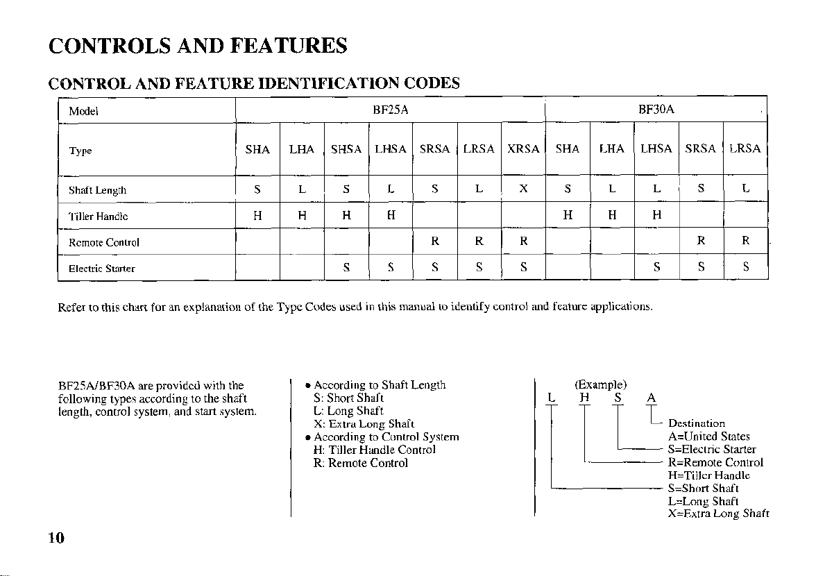
CONTROL AND FEATURE IDENTIFICATION CODES
Electric Stater
Refer to this chart for an explanation of the Type Codes used in this manual to identify control and feature applications.
BF25AlBF30A are provided with the
following types according to the shaft
length, control system, and start system.
S
0
According to Shaft Length
S:
Short Shaft
L: Long Shaft
X:
Extra Long Shaft
0
According to Control System
H:
Tiller Handle Control
R: Remote Control
S
S
S
(Example)
S S
S
Destination
A=United States
S=Electric Starter
R=Remote Control
H=Tiller Handle
S=Short Shaft
L=Long Shaft
X=Extra
Long
1
LRSA
L
R
S
Shaft
10
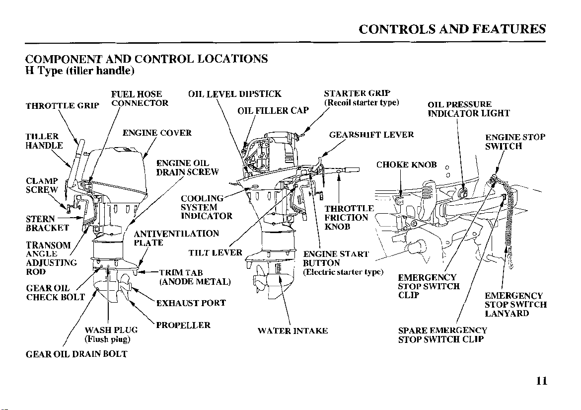
COMPONENT AND CONTROL LOCATIONS
H
Type (tiller handle)
FUEL HOSE OIL LEVEL DIPSTICK STARTER GRIP
THROTTLE GRIP
\
I
\
OIL/FILLERCAP
/p""il
CONTROLS AND FEATURES
starter type) OIL INDICATOR PRESSURE LIGHT
I
RSHIFT LEVER
WASH I PLUG \PROPELLER WATER \ INTAKE SPARE EMERGENCY
(Flush
/
GEAR OIL DRAIN BOLT
plug)
DRAIN SCREW
EXHAUST PORT
CHOKE KNOB
STOP SWITCH CLIP
0
STOP
SWITCH
LANYARD
11
CONTROLS AND FEATURES
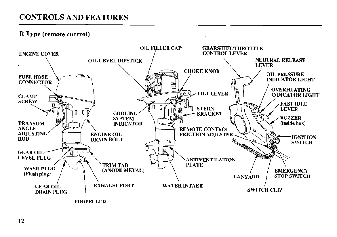
R
Type
(remote
control)
OIL FILLER CAP
OIL PRESSURE
LEVEL PLUG
GEAR OIL EXHAUST PORT WATER INTAKE
DRAIN PLUG
PROPELLER
12
TILT LEVER
OVERHEATING
INDICATOR LIGHT
STOP SWITCH
I
SWITCH CLIP
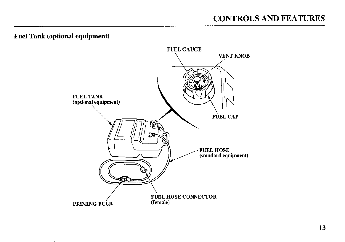
Fuel Tank (optional equipment)
FUEL TANK
FUEL GAUGE
\
CONTROLS AND FEATURES
VENT KNOB
(standard equipment)
PRIMING BULB
/
HOSE
FUEL
(female)
CONNECTOR
13
CONTROLS AND FEATURES
CONTROLS
H
Type (tiller handle)
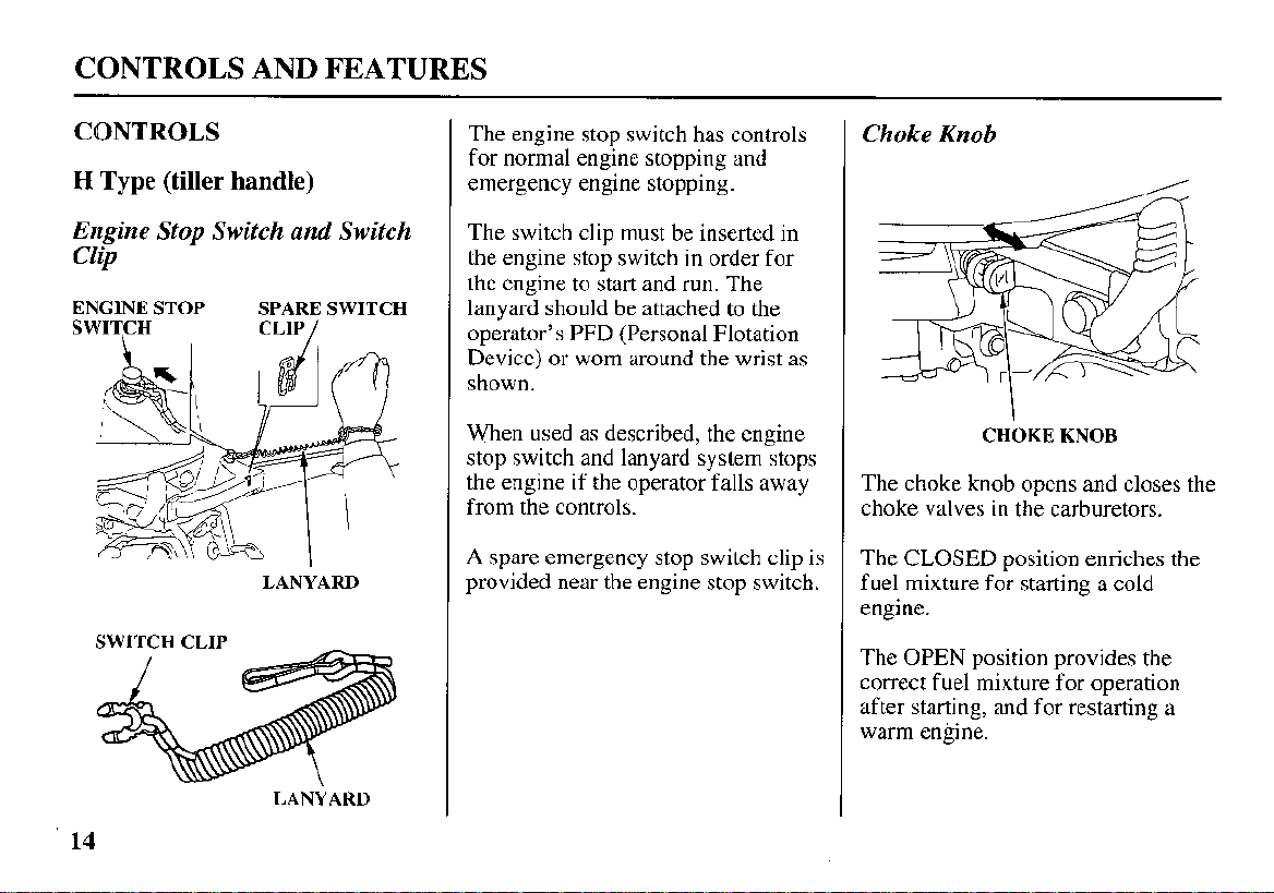
Engine
Stop
Switch
Cl@
ENGINE STOP
SWITCH
SWITCH CLIP
and
Switch
SPARE SWITCH
CLIP
/
LANYARD
The engine stop switch has controls
for normal engine stopping and
emergency engine stopping.
The switch clip must be inserted in
the engine stop switch in order for
the engine to start and
lanyard should be attached to the
operator’s PFD (Personal Flotation
Device) or worn around
shown.
When used as described, the engine
stop switch and lanyard system stops
the engine if the operator falls away
from the controls.
A spare emergency stop switch clip is
provided near the engine stop switch.
run.
the
The
wrist as
Choke
The choke knob opens and closes the
choke valves in the carburetors.
The CLOSED position enriches the
fuel mixture for starting a cold
engine.
The
correct fuel mixture for operation
after starting, and for restarting a
warm engine.
Knob
OPEN
/
CHOKE KNOB
position provides the
14
LANYARD
CONTROLS AND FEATURES
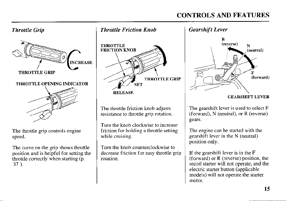
Throttle Grip
THROTTLE GRIP
THROTTLE OPENING INDICATOR
The throttle grip controls engine
speed.
The curve on the grip shows throttle
position and is helpful for setting the
throttle correctly when starting (p.
37
).
/
Throttle Friction Knob
THROTTLE
FRICTION KNOB
RELEASE
The throttle friction knob adjusts
resistance to throttle grip rotation.
Turn the knob clockwise to increase
friction for holding a throttle setting
while cruising.
Turn the knob counterclockwise to
decrease friction for easy throttle grip
rotation.
Gearshift Lever
R
GEARSHIFT LEVER
The gearshift lever is used to select
(forward), N (neutral), or R (reverse)
gears.
The engine can be started with the
gearshift lever in the
position only.
If the gearshift lever is in the
(forward) or R (reverse) position, the
recoil starter will not operate, and the
electric starter button (applicable
models) will not operate the starter
motor.
N
(neutral)
F
F
15
CONTROLS AND FEATURES
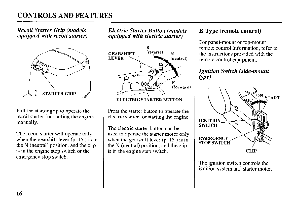
Recoil Starter Grip (models
equipped with recoil starter)
I
'\
A
,"
Pull the starter grip to operate the
recoil starter for starting the engine
manually.
The recoil starter will operate only
when the gearshift lever (p.
the
N
(neutral) position, and the clip
is
in the engine stop switch
emergency stop switch.
\
STARTER GRIP
15
or
)
the
is in
Electric Starter Button (models
equipped with electric starter)
R
GEARSHIFT
LEVER
Press the starter button to operate the
electric starter
The electric starter button can be
used to operate the starter motor only
when the gearshift lever (p.
the
is in the engine stop switch.
\
ELECTRIC STARTER BUTTON
N
(neutral) position, and the clip
(reverse) N
(neutral)
for
starting the engine.
15
)
is in
R
Type (remote control)
For panel-mount or top-mount
remote control information, refer to
the instructions provided with the
remote control equipment.
Ignition Switch (side-mount
type)
EMERGENCY
STOP SWITCH
CLIP
The ignition switch controls the
ignition system and starter motor.
16
CONTROLS AND FEATURES
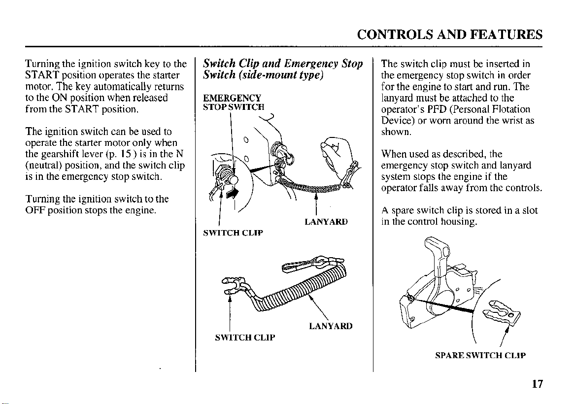
Turning the ignition switch key to the
START position operates the starter
motor. The key automatically returns
to the
ON
position when released
from the START position.
The ignition switch can be used to
operate the starter motor only when
the gearshift lever (p.
(neutral) position, and the switch clip
is in the emergency stop switch.
Turning the ignition switch to the
OFF position stops the engine.
15
)
is in the
N
Switch Clip
and
Emergency Stop
Switch (side-mount type)
EMERGENCY
STOP SWITCH
I
SWITCH CLIP
I
SWITCH CLIP
LANYARD
LANYARD
The switch clip must be inserted
the emergency stop switch in order
for
the engine to start and run. The
lanyard must be attached
operator’s PFD (Personal Flotation
Device) or worn around the wrist as
shown.
When used as described, the
emergency stop switch and lanyard
system stops the engine
operator falls away from the controls.
A spare switch clip is stored in a slot
in the control housing.
to
if
in
the
the
SPARE SWITCH CLIP
17
CONTROLS AND FEATURES
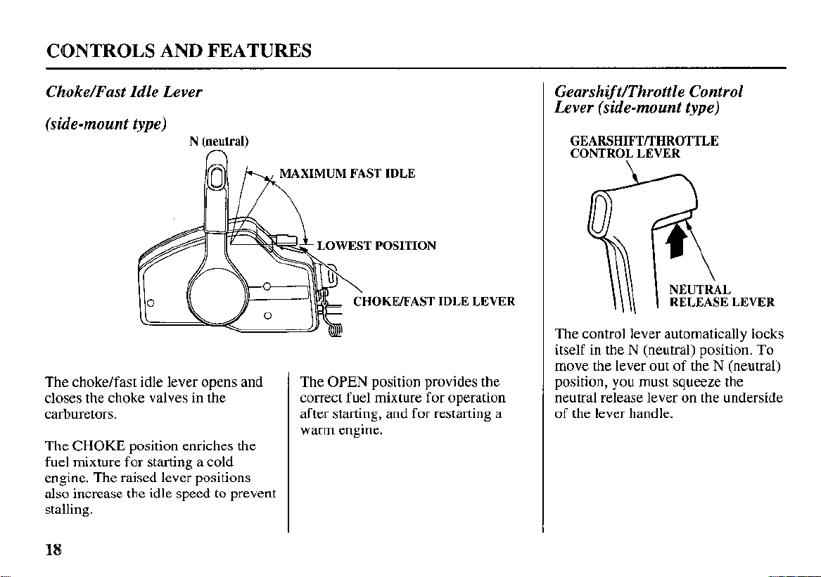
Choke/Fast Idle Lever
(side-mount type)
N
(neutral)
n
LL
The choke/fast idle lever opens and
closes the choke valves in the
carburetors.
The
CHOKE
fuel mixture for starting a cold
engine. The raised lever positions
also increase the idle speed to prevent
stalling.
position enriches the
LOWEST
The
OPEN
correct fuel mixture for operation
after starting, and for restarting a
warm engine.
POSITION
IDLE LEVER
position provides the
Gearshift/Throttle Control
Lever (side-mount type)
GEARSHIFTRHROTTLE
CONTROL LEVER
HL
The control lever automatically locks
itself in the
move the lever out
position, you must squeeze the
neutral release lever on the underside
of the lever handle.
N
RELEASE LEVER
(neutral) position.
of
the N (neutral)
To
18
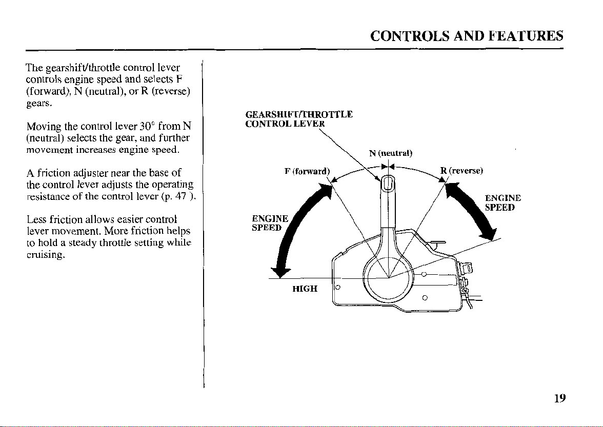
The gearshifdthrottle control lever
controls engine speed and selects
(forward), N (neutral), or R (reverse)
gears.
Moving the control lever
(neutral) selects the gear, and further
movement increases engine speed.
A
friction adjuster near the base of
the control lever adjusts the operating
resistance
Less friction allows easier control
lever movement. More friction helps
to hold a steady throttle setting while
cruising.
of
the control lever
30"
F
from
(p.
47
N
CONTROLS AND FEATURES
GEARSHIFTD'HROTTLE
CONTROL LEVER
\
\
N
(neutral)
).
19
CONTROLS AND FEATURES
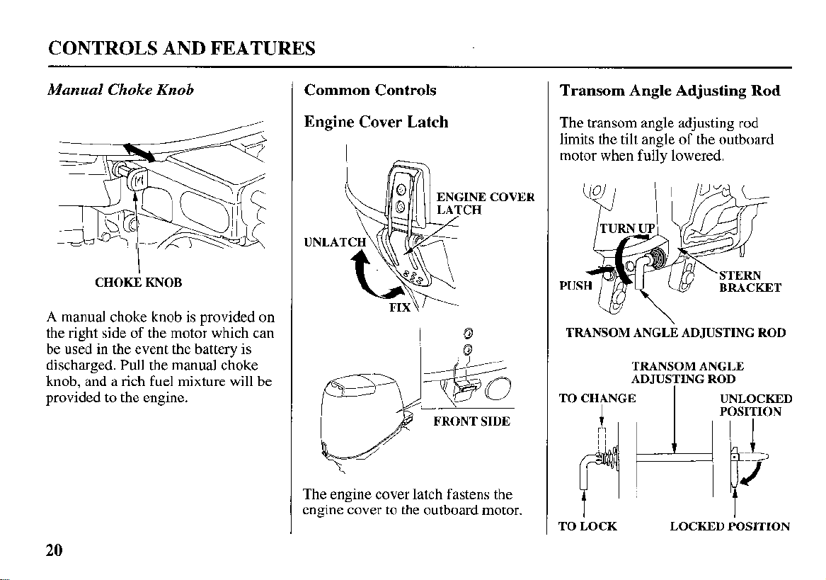
Manual
A manual choke knob
the right side of the motor which can
be used in the event the battery is
discharged. Pull the manual choke
knob, and a rich fuel mixture will be
provided to the engine.
Choke
CHOKE KNOB
Knob
is
provided on
Common Controls
Engine Cover
UNLA
Latch
COVER
0
Io
FRONT SIDE
The engine cover latch fastens the
engine cover to the outboard motor.
Transom Angle Adjusting Rod
The transom angle adjusting rod
of
limits the tilt angle
motor when fully lowered.
TRANSOM ANGLE ADJUSTING
TRANSOM ANGLE
ADJUSTING ROD
TO CHANGE
TO LOCK
~
the outboard
ROD
1
,:iJ7
LOCKED POSITION
20
CONTROLS AND FEATURES
Proper adjustment prevents the
outboard motor from being trimmed
too low (p.
49
).
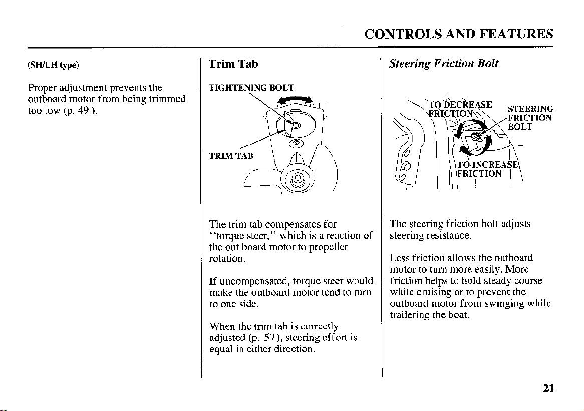
Trim
Tab
TIGHTENING BOLT
TRIM TAB
The trim tab compensates for
“torque steer,” which is a reaction of
the out board motor to propeller
rotation.
If
uncompensated, torque steer would
make the outboard motor tend to turn
to one side.
is
When the trim tab
adjusted (p.
equal in either direction.
57),
correctly
steering effort is
Steering Friction Bolt
.
The steering friction bolt adjusts
steering resistance.
Less friction allows the outboard
motor to turn more easily. More
friction helps to hold steady course
while cruising or to prevent the
outboard motor from swinging while
trailering the boat.
21
CONTROLS AND FEATURES
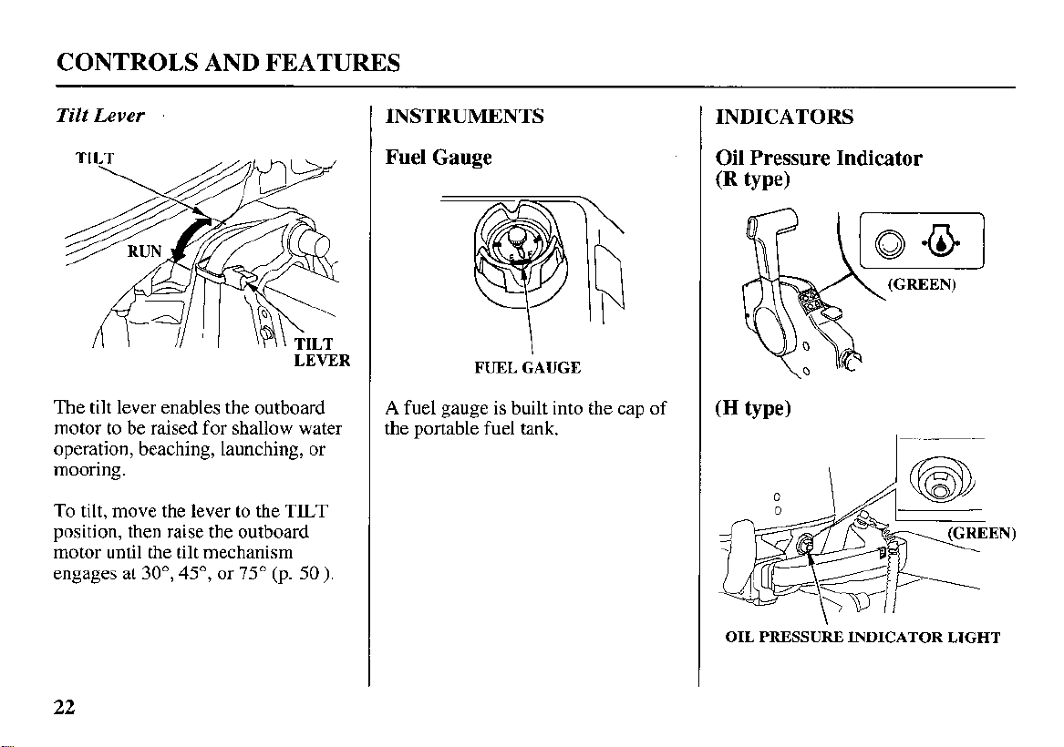
Tilt
Lever
INSTRUMENTS
INDICATORS
LEVER
The
tilt
lever enables the outboard
motor to be raised for shallow water
operation, beaching, launching, or
mooring.
To tilt, move the lever to the TILT
position, then raise the outboard
motor until the tilt mechanism
engages at
30°,
45",
or
75"
(p.
50
).
Fuel Gauge
FUEL GAUGE
A
fuel gauge is built into the cap of
the portable fuel tank.
Oil
Pressure Indicator
(R
type)
I
0
I
A@
OIL PRESSURE INDICATOR LIGHT
22
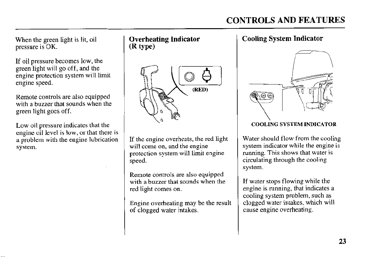
CONTROLS AND FEATURES
When the green light is lit, oil
pressure is
If oil pressure becomes low, the
green light will
engine protection system will limit
engine speed.
Remote controls are also equipped
with a buzzer that sounds when the
green light goes off.
Low oil pressure indicates that the
engine oil level is low, or that there is
a problem with the engine lubrication
system.
OK.
go
off, and the
Overheating Indicator
(R
type)
If the engine overheats, the red light
will come on, and the engine
protection system will limit engine
speed.
Remote controls are also equipped
with a buzzer that sounds when the
red light comes on.
Engine overheating may be the result
of clogged water intakes.
Cooling System Indicator
COOLING
Water should flow from the cooling
system indicator while the engine is
running. This shows that water is
circulating through the cooling
system.
If water stops flowing while the
engine is running, that indicates a
cooling system problem, such as
clogged water intakes, which will
cause engine overheating.
SYSTEM
INDICATOR
23
CONTROLS AND FEATURES
OTHER FEATURES
Overrev Limiter
The engine is equipped with an
overrev limiter to prevent the
possibility of mechanical damage
from excessive engine speed.
The overrev limiter may be activated
during operation, limiting engine
speed, if the outboard motor is tilted
excessively, or when ventilation
occurs during a sharp turn.
If
the overrev limiter is activated,
check the trim angle of the outboard
motor.
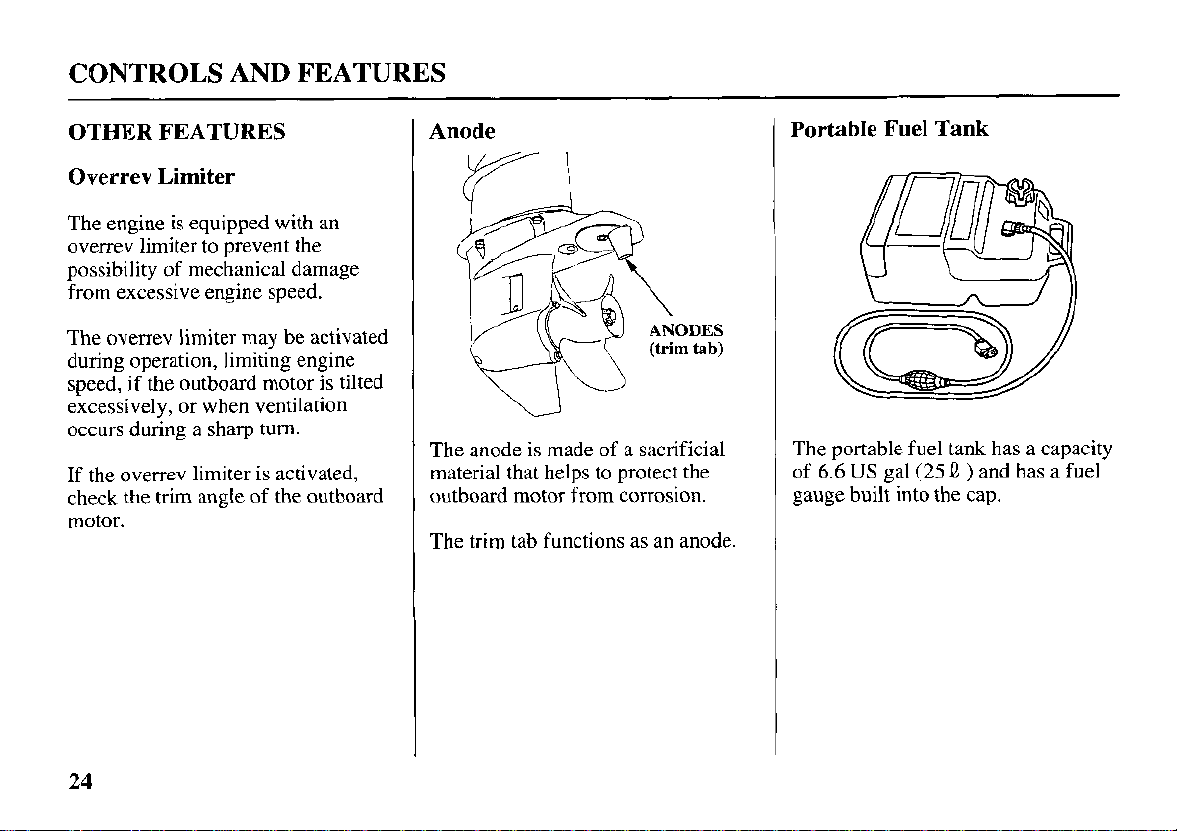
Anode
The anode
material that helps to protect the
outboard motor from corrosion.
The trim tab functions as an anode.
is
made of a sacrificial
Portable
The portable fuel tank has a capacity
of
6.6
gauge built into the cap.
US
Fuel
Tank
gal (25
Q
)
and has a fuel
24
CONTROLS AND FEATURES
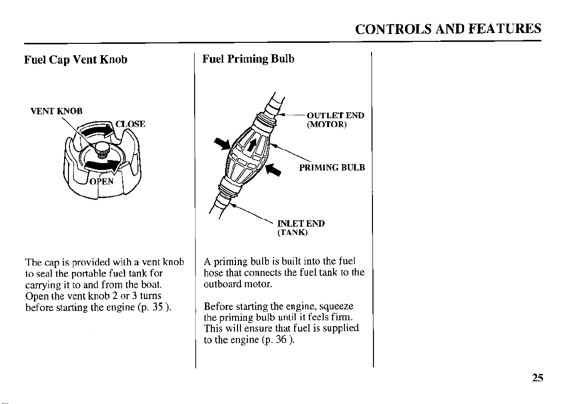
Fuel
Cap
Vent Knob
VENT KNOB
The cap is provided with a vent knob
to seal the portable fuel tank for
carrying it to and from the boat.
2 or
3
Open the vent knob
before starting the engine (p.
turns
35
).
Fuel Priming Bulb
OUTLET END
'
INLET END
(TANK)
A
priming bulb is built into the
hose that connects the fuel tank to the
outboard motor.
Before starting the engine, squeeze
the priming bulb until it feels
This will ensure that fuel is supplied
to the engine (p.
36
).
fuel
firm.
25
INSTALLATION
Correct and secure installation is
essential for safe boating and good
performance. Follow the installation
instructions provided in this manual.
POWER REQUIREMENTS
Before installation, check to be sure
that the outboard motor does not
exceed the recommended maximum
horsepower for the boat on which
is
to
be installed. Refer to the boat’s
certification plate for recommended
maximum horsepower.
certification plate information is not
available, contact the boat dealer or
manufacturer.
For most applications, the outboard
motor should have a horsepower
rating which provides
maximum recommended horsepower
for the boat.
If
80%
the
of the
it
BOAT TRANSOM REQUIREMENTS
Honda BF25A and BF3
motors can be installed
transom having a thickness range of
-
2.2 inches (35
1.3
OA outboarc
on
a boat
-
57 mm).
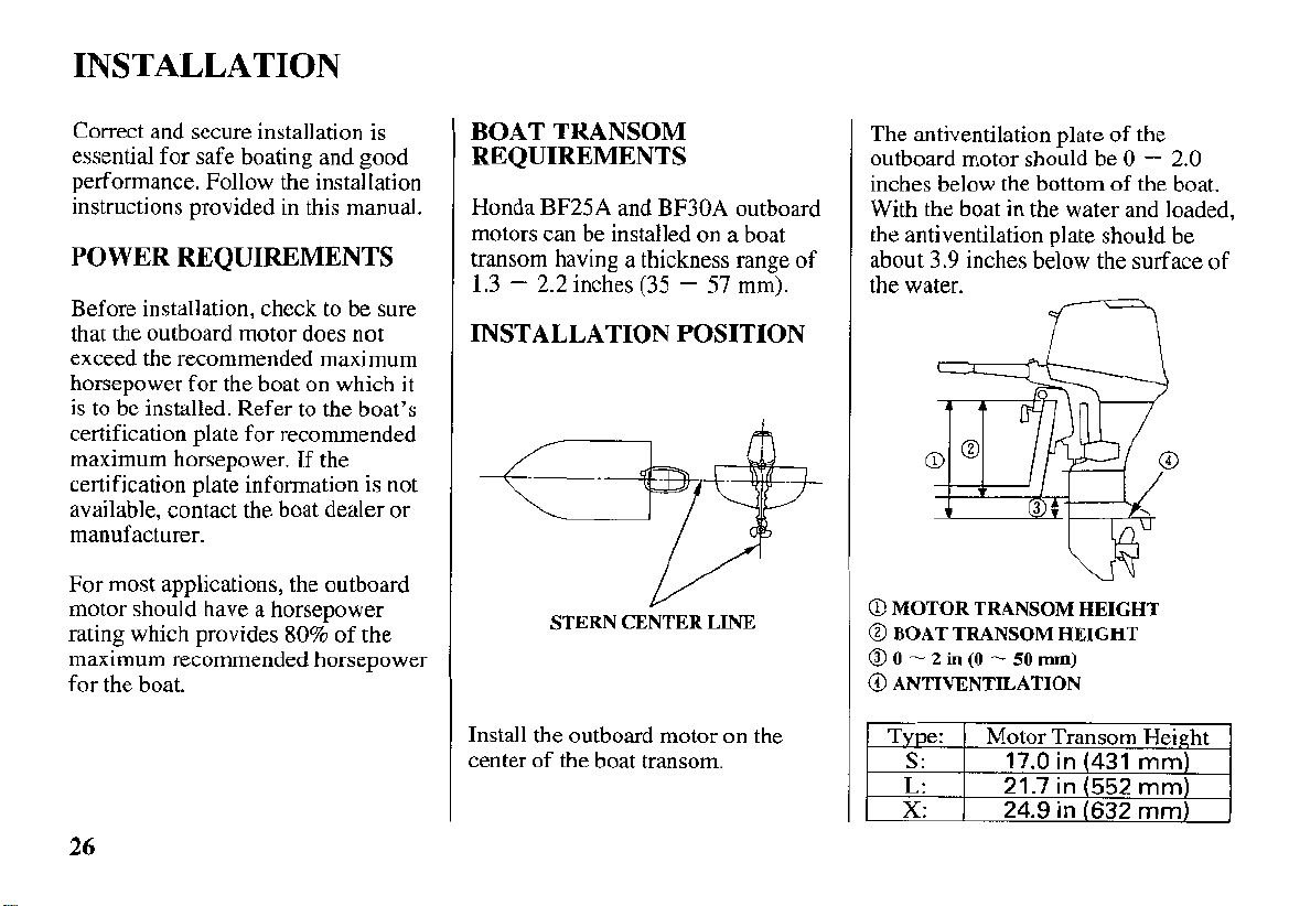
INSTALLATION POSITION
STERN CENTER LINE
Install the outboard motor on the
center of the boat transom.
The antiventilation plate of the
outboard motor should be
inches below the bottom of the boat.
With the boat in the water and loaded,
the antiventilation plate should be
about
3.9
inches below the surface of
the water.
@
MOTOR TRANSOM HEIGHT
@
BOAT TRANSOM HEIGHT
00
-
2in(0 - 50mm)
@
ANTIVENTILATION
Type:
S:
L:
X:
Motor Transom Height
17.0
21.7
24.9
I
in
in
in
hU
(431
(552
(632
0
-
mm)
mm)
mm)
2.0
26
INSTALLATION
If the outboard motor is installed too
low, the boat will squat and be hard
to plane,
high-speed stability will be reduced.
If
high, that will cause ventilation.
Optimum installation height vanes
with boat type and bottom shape.
Contact the boat manufacturer for
any special recommendations that are
unique to a specific model of boat.
If
to accommodate the outboard motor,
contact the boat manufacturer and
follow their recommendations for
corrective action.
it will tend to porpoise, and
the outboard motor is installed too
the transom needs to be modified
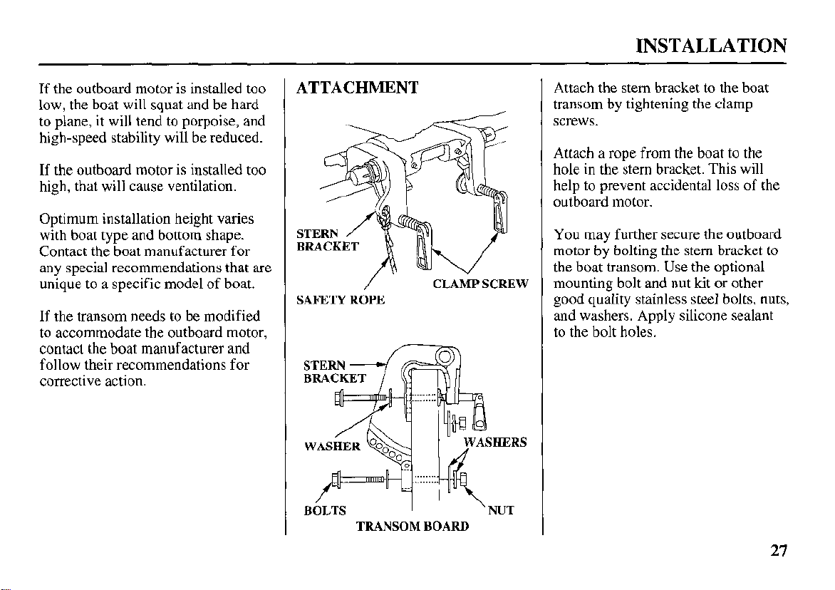
ATTACHMENT
/
SAFETY
ROPE
CLAMP SCREW
Attach the stem bracket to the boat
transom by tightening the clamp
screws.
Attach a rope from the boat to the
hole in the stem bracket. This will
help to prevent accidental
outboard motor.
You may further secure the outboard
motor by bolting the stern bracket
the boat transom. Use the optional
mounting bolt and nut
good quality stainless steel bolts, nuts,
and washers. Apply silicone sealant
to the bolt holes.
kit
loss
of the
or other
to
TRANSOM BOARD
27
INSTALLATION
TRANSOM ANGLE
ADJUSTMENT
Use the transom angle adjustment rod
(p.
34
)
to adjust the angle of the
outboard motor
perpendicular to the surface
water.
so the propeller is
of
the
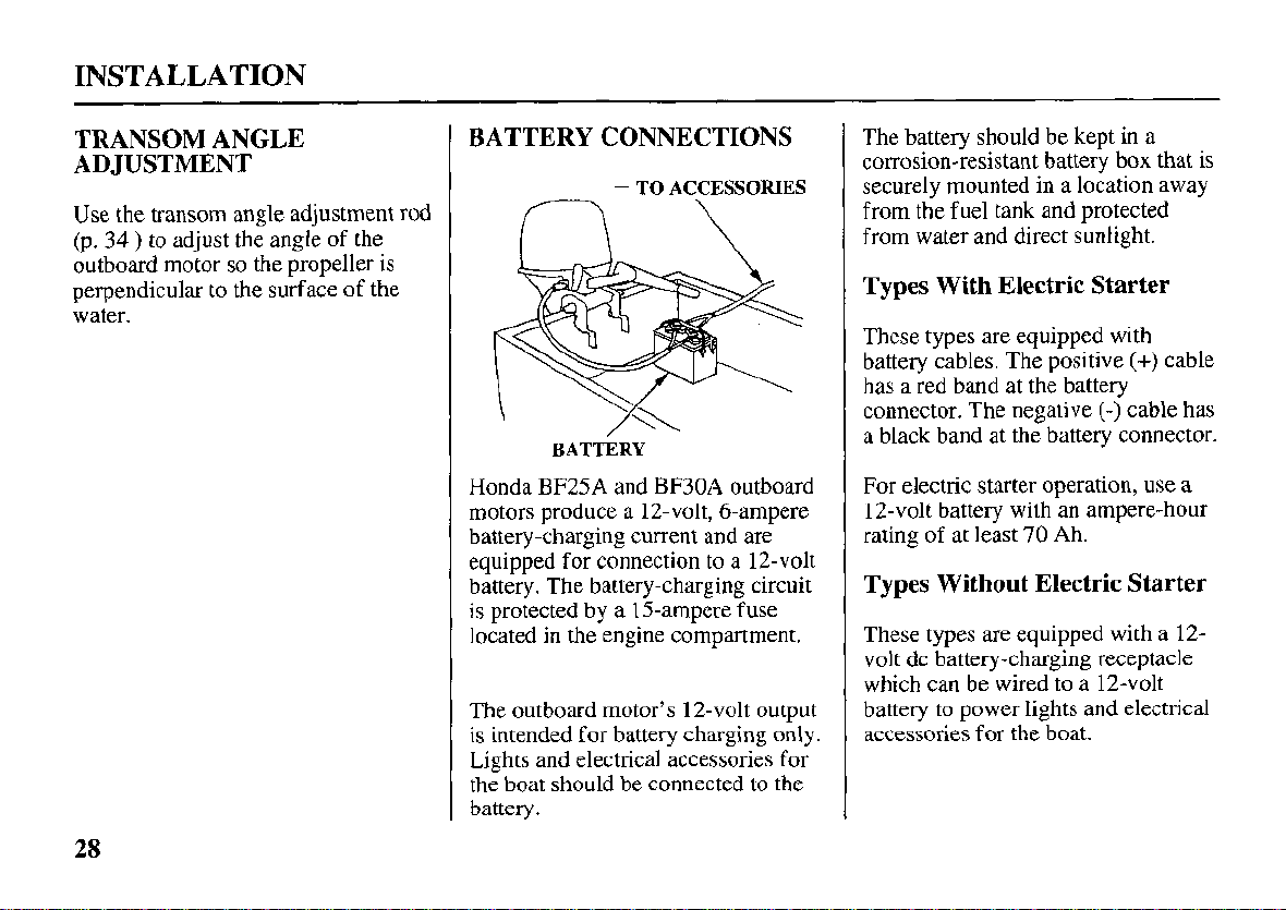
BATTERY CONNECTIONS
BATTERY
Honda BF25A and BF30A outboard
motors produce a 12-volt, 6-ampere
battery-charging current and are
equipped for connection to a 12-volt
battery. The battery-charging circuit
is protected by a 15-ampere fuse
located
The outboard motor’s 12-volt output
is intended for battery charging only.
Lights and electrical accessories for
the boat should be connected to the
battery.
in
the engine compartment.
The battery should be kept in a
corrosion-resistant battery box that is
securely mounted in a location away
from the fuel tank and protected
from water and direct sunlight.
Types With Electric Starter
These types are equipped with
battery cables. The positive
has a red band at the battery
connector. The negative
a black band at the battery connector.
For electric starter operation, use a
12-volt battery with an ampere-hour
rating of at least
70
Ah.
(+)
(-)
cable has
cable
Types Without Electric Starter
These types are equipped with a 12-
volt dc battery-charging receptacle
which can be wired to a 12-volt
battery to power lights and electrical
accessories for the boat.
28
 Loading...