


Henny Penny
Pressure Fryer-Gas
Model PFG-691
OPERATOR’S MANUAL

Model 691
LIMITED WARRANTY FOR HENNY PENNY EQUIPMENT
Subject to the following conditions, Henny Penny Corporation makes the following limited warranties to the original purchaser only for Henny Penny appliances and replacement parts:
NEW EQUIPMENT: Any part of a new appliance, except baskets, lamps, and fuses, which proves to be defective in material or workmanship within two (2) years from date of original installation, will be repaired or replaced without charge F.O.B. factory, Eaton, Ohio, or F.O.B. authorized distributor. Baskets will be repaired or replaced for ninety (90) days from date of original installation. Lamps and fuses are not covered under this Limited Warranty. To validate this warranty, the registration card for the appliance must be mailed to Henny Penny within ten (10) days after installation.
FILTER SYSTEM: Failure of any parts within a fryer filter system caused by the use of the non-OEM filters or other unapproved filters is not covered under this Limited Warranty.
REPLACEMENT PARTS: Any appliance replacement part, except lamps and fuses, which proves to be defective in material or workmanship within ninety (90) days from date of original installation will be repaired or replaced without charge F.O.B. factory, Eaton, Ohio, or F.O.B. authorized distributor.
The warranty for new equipment covers the repair or replacement of the defective part and includes labor charges and maximum mileage charges of 200 miles round trip for a period of one (1) year from the date of original installation.
The warranty for replacement parts covers only the repair or replacement of the defective part and does not include any labor charges for the removal and installation of any parts, travel, or other expenses incidental to the repair or replacement of a part.
EXTENDED FRYPOT WARRANTY: Henny Penny will replace any frypot that fails due to manufacturing or workmanship issues for a period of up to seven (7) years from date of manufacture. This warranty shall not cover any frypot that fails due to any misuse or abuse, such as heating of the frypot without shortening.
0 TO 3 YEARS: During this time, any frypot that fails due to manufacturing or workmanship issues will be replaced at no charge for parts, labor, or freight. Henny Penny will either install a new frypot at no cost or provide a new or reconditioned replacement fryer at no cost.
3 TO 7 YEARS: During this time, any frypot that fails due to manufacturing or workmanship issues will be replaced at no charge for the frypot only. Any freight charges and labor costs to install the new frypot as well as the cost of any other parts replaced, such as insulation, thermal sensors, high limits, fittings, and hardware, will be the responsibility of the owner.
Any claim must be presented to either Henny Penny or the distributor from whom the appliance was purchased. No allowance will be granted for repairs made by anyone else without Henny Penny’s written consent. If damage occurs during shipping, notify the sender at once so that a claim may be filed.
THEABOVE LIMITED WARRANTYSETS FORTH THE SOLE REMEDYAGAINSTHENNYPENNYFORANYBREACH OF WARRANTYOR OTHER TERM. BUYERAGREES THAT NO OTHER REMEDY(INCLUDING CLAIMS FORANYINCIDENTALOR CONSEQUENTIALDAMAGES) SHALLBEAVAILABLE.
The above limited warranty does not apply (a) to damage resulting from accident, alteration, misuse, or abuse; (b) if the equipment’s serial number is removed or defaced; or (c) for lamps and fuses. THE ABOVE LIMITED WARRANTY IS EXPRESSLYIN LIEU OFALL OTHER WARRANTIES, EXPRESS OR IMPLIED, INCLUDING MERCHANTABILITYAND FITNESS,ANDALLOTHER WARRANTIESARE EXCLUDED. HENNYPENNYNEITHERASSUMES NORAUTHORIZESANY PERSON TOASSUME FOR ITANYOTHER OBLIGATION OR LIABILITY.
Revised 01/01/07
FM05-010-J
Revised 08-01-10

Model 691
This manual should be retained in a convenient location for future reference.
A wiring diagram for this appliance is located on the rear shroud cover of the control panel.
Post in a prominent location, instructions to be followed if user smells gas. This information should be obtained by consulting the local gas supplier.
Do not obstruct the flow of combustion and ventilation air.Adequate clearance must be left all around appliance for sufficient air to the combustion chamber.
The Model PFG-691 Fryer is equipped with a continuous pilot. But Fryer cannot be operated without electric power. Fryer will automatically return to normal operation when power is restored.
To avoid a fire, keep appliance area free and clear from combustibles.
Improper installation, adjustment, alteration, service, or maintenance can cause property damage, injury, or death. Read the installation, operating, and maintenance
instructions thoroughly before installing or servicing this equipment.
DO NOT STORE OR USE GASOLINE OR OTHER FLAMMABLE VAPORS
AND LIQUIDS IN THE VICINITY OF THIS OR ANY OTHER APPLIANCE. FIRE OR EXPLOSION COULD RESULT.
803

Model 691
|
Technical Data for CE Marked Products |
||
Nominal Heat Input: |
Natural (I2H) = 26,4 kW |
(90,000 Btu/h) |
|
(Net) |
Natural (I2E) = 26,4 kW (90,000 Btu/h) |
||
|
Natural (I2S) = 23,75 kW (81,000 Btu/h) |
||
|
Liquid Propane (I3P) = 27,0 kW |
(92,000 Btu/h) |
|
Nominal Heat Input: |
Natural (I2H) = 29,3 kW |
(100,000 Btu/h) |
|
(Gross) |
Natural (I2E) = 29,3 kW (100,000 Btu/h) |
||
|
Natural (I2S) = 26,4 kW (90,000 Btu/h) |
||
|
Liquid Propane (I3P) = 29,3 kW |
(100,000 Btu/h) |
|
Supply Pressure: |
Natural (I2H) = 20 mbar |
|
|
|
Natural (I2E) = 20 mbar |
|
|
|
Natural (I2S) = 25 mbar |
|
|
|
Liquid Propane (I3P) = 37/50 mbar |
|
|
Test Point Pressure: |
Natural (I2H) = 8,7 mbar |
|
|
|
Natural (I2E) = 8,7 mbar |
|
|
|
Natural (I2S) = 8,7 mbar |
|
|
|
Liquid Propane (I3P) = 25 mbar |
|
|
Injector Size: |
Natural (I2H) = 2,51 mm |
|
|
Natural (I2E) = 2.51 mm
Natural (I2S) = 2.85 mm
Liquid Propane (I3P) = 1,04 mm
This appliance must be installed in accordance with the manufacturer’s instructions and the regulations in force and only used in a suitable ventilated location. Read the instructions fully before installing or using the appliance.
|
Datos Tecnicos Para Products CE |
||
Consumo Calorico Nominal: |
Gas Natural (I2H) = 26,4 kW |
(90,000 Btu/h) |
|
(Neto) |
Gas Natural (I2E) = 26,4 kW (90,000 Btu/h) |
||
|
Gas Natural (I2S) = 23,75 kW (81,000 Btu/h) |
||
|
Propano Licuado (I3P) = 27,0 kW |
(92,000 Btu/h) |
|
Consumo Calorico Nominal: |
Gas Natural (I2H) = 29,3 kW |
(100,000 Btu/h) |
|
(Bruto) |
Gas Natural (I2E) = 29,3 kW (100,000 Btu/h) |
||
|
Gas Natural (I2S) = 26,4 kW (90,000 Btu/h) |
||
|
Propano Licuado (I3P) = 29,3 kW |
(100,000 Btu/h) |
|
Presion De Alimentacion: |
Gas Natural (I2H) = 20 mbar |
|
|
|
Gas Natural (I2E) = 20 mbar |
|
|
|
Gas Natural (I2S) = 25 mbar |
|
|
|
Propano Licuado (I3P) = 37/50 mbar |
||
Presion En Ez Punto De Prueba: |
Gas Natural (I2H) = 8,7 mbar |
|
|
|
Gas Natural (I2E) = 8,7 mbar |
|
|
|
Gas Natural (I2S) = 8,7 mbar |
|
|
|
Propano Licuado (I3P) = 25 mbar |
|
|
Diámetro Boquilla: |
Gas Natural (I2H) = 2,51 mm |
|
|
Gas Natural (I2E) = 2.51 mm
Gas Natural (I2S) = 2.85 mm
Propano Licuado (I3P) = 1,04 mm
Este equipo debe instalarse únicamente en un recinto adecuadameute ventilado y conforme a las indicaciones del fabricante y a las normas vigentes. Lea completamente las instrucciones antes de instalar o usar este equipo.

Model 691
HENNY PENNY
8 HEAD GAS PRESSURE FRYER
SPECIFICATIONS
Height |
61" (155 cm) |
Width |
24" (61 cm) |
Depth |
41¾" (106 cm) |
Floor Space |
Approximately 7 sq. ft. (0.65 sq. m.) |
Pot Capacity |
8 head of chicken (24 lbs.) (10.9 kg) |
|
130 lbs. shortening (59 kg) |
Electrical |
120 VAC, 1 Phase, 50/60 Hz, 10 Amp, 3 Wire Service |
|
240 VAC, 1 Phase, 50/60 Hz, 5 Amp, 3 Wire Service |
Heating |
Propane or Natural Gas; 100,000 Btu/h (105.51 MJ/hr) |
Pressure |
9 psi operating pressure (621 mbar) |
|
14.5 psi safety relief pressure (999 mbar) |
ShippingWeight |
Approximately 935 lbs. (424 kg) |
Accessories Shipped |
Eight wire baskets, basket carrier, and standard cleaning |
|
brushes |
Adata plate, located on the right side panel, gives the information of the type of fryer,
serial number, warranty date, and other information pertaining to fryer. Also, the serial number is stamped on the outside of the frypot. See figure below.

Model 691
|
|
TABLE OF CONTENTS |
|
Section |
|
|
Page |
Section 1. |
INTRODUCTION .................................................................................................... |
1-1 |
|
|
1-1. |
Pressure Fryer ............................................................................................... |
1-1 |
|
1-2. |
Proper Care ................................................................................................... |
1-1 |
|
1-3. |
Assistance ..................................................................................................... |
1-1 |
|
1-4. |
Safety ............................................................................................................ |
1-2 |
Section 2. |
INSTALLATION ...................................................................................................... |
2-1 |
|
|
2-1. |
Introduction.................................................................................................... |
2-1 |
|
2-2. |
Unpacking Instructions .................................................................................. |
2-1 |
|
2-3. |
Selecting the Fryer Location ......................................................................... |
2-4 |
|
2-4. |
Leveling the Fryer ......................................................................................... |
2-4 |
|
2-5. |
Ventilation of Fryer ........................................................................................ |
2-5 |
|
2-6. |
Gas Supply ..................................................................................................... |
2-5 |
|
2-7. |
Gas Piping ..................................................................................................... |
2-5 |
|
2-8. |
Gas Pressure Regulator Setting .................................................................... |
2-8 |
|
2-9. |
Electrical Requirements ................................................................................ |
2-8 |
|
2-10. |
Testing the Fryer ........................................................................................... |
2-9 |
|
2-11. |
Gas Leak Test ............................................................................................... |
2-9 |
Section 3. |
OPERATING INSTRUCTIONS .............................................................................. |
3-1 |
|
|
3-1. |
Operating Controls ........................................................................................ |
3-1 |
|
3-2. |
Lid Operation................................................................................................. |
3-4 |
|
3-3. |
Switches and Indicators ................................................................................ |
3-5 |
|
3-4. |
Clock Set ....................................................................................................... |
3-8 |
|
3-5. |
Filling orAdding Shortening ........................................................................... |
3-10 |
|
3-6. |
Product Racking Recommendations ............................................................. |
3-11 |
|
3-7. |
Basic Operation ............................................................................................. |
3-12 |
|
3-8. |
Care of the Shortening .................................................................................. |
3-16 |
|
3-9. |
Filtering Instructions ...................................................................................... |
3-16 |
|
3-10. |
Changing the Filter Envelope......................................................................... |
3-19 |
|
3-11. |
Lighting and Shutdown of the Burners .......................................................... |
3-21 |
|
3-12. |
Cleaning the Frypot ....................................................................................... |
3-22 |
|
3-13. |
Filter Pump Motor Protector-Manual Reset ................................................. |
3-24 |
|
3-14. |
Regular Maintenance Schedule ..................................................................... |
3-24 |
|
3-15. |
Preventive Maintenance ................................................................................ |
3-25 |
|
3-16. |
Programming ................................................................................................. |
3-28 |
|
3-17. |
Special Program Mode .................................................................................. |
3-34 |
|
3-18. |
Data Logging, Heat Control, Tech, and Stat Modes ..................................... |
3-41 |
|
3-19. |
Information Mode .......................................................................................... |
3-42 |
Section 4. |
TROUBLESHOOTING ........................................................................................... |
4-1 |
|
|
4-1. |
Troubleshooting Guide ................................................................................... |
4-1 |
|
4-2. |
Error Codes ................................................................................................... |
4-2 |
|
GLOSSARY .............................................................................................................. |
G-1 |
|
Distributors Lists - Domestic and International |
|
||
1104 |
i |

|
Model 691 |
|
|
|
|
|
SECTION 1. INTRODUCTION |
|
1-1. PRESSURE FRYER |
The Henny Penny Pressure Fryer is a basic unit of food processing |
|
|
equipment. It has found wide application in institutional and com- |
|
|
mercial food service operations. |
|
P-H-T |
A combination of pressure, heat, and time is automatically |
|
|
controlled to produce the optimum in a tasty, appealing |
|
|
product. |
|
Pressure |
Pressure is basic to this method of food preparation. The pressure |
|
|
is developed from the natural moisture of the food. The patented lid |
|
|
traps this moisture and uses it as steam. Because the steam builds |
|
|
rapidly, the greater part of the natural juices are retained within the |
|
|
food.Adeadweight assembly vents excess steam from the pot and |
|
|
maintains constant live steam pressure. |
|
Heat |
Heat generated is another important factor of the pressure fryer. |
|
|
Energy savings is realized due to the unit’s short frying time, |
|
|
low temperature, and heat retention of the stainless steel frypot. |
|
Time |
Time is important because the shorter time involved in frying |
|
|
foods results in additional economies for the user. Foods are |
|
|
table ready in less time than it would take to fry them in a con- |
|
|
ventional open-type fryer. |
|
|
As ofAugust 16, 2005, the Waste Electrical and Electronic Equip- |
|
|
ment directive went into effect for the European Union. Our |
|
|
products have been evaluated to the WEEE directive. We have |
|
|
also reviewed our products to determine if they comply with the |
|
|
Restriction of Hazardous Substances directive (RoHS) and have |
|
|
redesigned our products as needed in order to comply. To continue |
|
|
compliance with these directives, this unit must not be disposed as |
|
|
unsorted municipal waste. For proper disposal, please contact |
|
|
your nearest Henny Penny distributor. |
|
1-2. PROPER CARE |
As in any unit of food service equipment, the Henny Penny |
|
|
Pressure Fryer does require care and maintenance. Requirements |
|
|
for the maintenance and cleaning are contained in this manual and |
|
|
must become a regular part of the operation of the unit at all times. |
|
1-3. ASSISTANCE |
Should you require outside assistance, just call your local indepen- |
|
|
dent Henny Penny distributor in your area, call Henny Penny |
|
|
Corp. at 1-800-417-8405 toll free or 1-937-456-8405, or visit us |
|
|
online at www.hennypenny.com |
|
207 |
1-1 |

Model 691
1-4. SAFETY |
The Henny Penny Pressure Fryer has may safety features |
|
incorporated. However, the only way to ensure a safe operation |
|
is to fully understand the proper installation, operation, and |
|
maintenance procedures. The instructions in this manual have |
|
been prepared to aid you in learning the proper procedures. |
|
Where information is of particular importance or safety related, |
|
the words DANGER, WARNING, CAUTION, and NOTICE are |
|
used. Their usage is described below. |
|
SAFETYALERT SYMBOLis used with DANGER, |
|
WARNING, or CAUTION which indicates a personal injury |
|
type hazard. |
|
NOTICE is used to highlight especially important information. |
|
CAUTION used without the safety alert symbol indicates |
|
a potentially hazardous situation which, if not avoided, |
|
may result in property damage. |
|
CAUTION used with the safety alert symbol indicates a |
|
potentially hazardous situation which, if not avoided, |
|
may result in minor or moderate injury. |
|
WARNING indicates a potentially hazardous situation |
|
which, if not avoided, could result in death or serious |
|
injury. |
|
DANGER INDICATES AN IMMINENTLY |
|
HAZARDOUS SITUATION WHICH, IF NOT |
|
AVOIDED, WILL RESULT IN DEATH OR SERIOUS |
|
INJURY. |
1-2 |
403 |
Model 691
SECTION 2. INSTALLATION
2-1. INTRODUCTION
2-2. UNPACKING INSTRUCTIONS
This section provides the installation and unpacking instructions for the Henny Penny PFG-691.
Installation of this unit should be performed only by a qualified service technician.
Do not puncture the fryer with any objects such as
drills or screws as electrical shock or component damage could result.
Any shipping damage should be noted in the presence of the delivery agent and signed prior to his or her departure.
1.Cut and remove the plastic bands from the main box.
2.Remove the box lid and lift the main box off the fryer.
3.Remove four corner packing supports.
4.Cut the stretch film from around the carrier/rack box and remove it from the top of the fryer lid.
5.Cut and remove the metal bands holding the fryer to the pallet.
All counterweights must be loaded before unlatching the lid, or personal injury could result.
6.Remove the fryer from the pallet.
Take care when moving the fryer to prevent personal injury. The fryer weighs approximately 935 lbs. (424 kg).
1104 |
2-1 |
Model 691
2-2. UNPACKING |
7. Remove the counterweights, which are strapped to the |
INSTRUCTIONS |
pallet under the fryer, from the pallet. |
(Continued) |
|
Do not drop. The counterweights weigh approximately 18 lbs. (8.1 kg) each. Handle with care, or personal injury could result.
8.Remove rear service cover.
9.Load the 7 weights into the counterweight assembly.
10.Replace rear service cover.
To avoid personal injury and assure safe operation of unit, rear service cover must be in place.
11.Cut warning tags from the lid assembly. The lid may now be unlatched.
12.Remove the accessories from inside the filter drain pan.
The fittings for installing the gas line are in a separate box, along with the accessories, in the filter drain pan.
13.Prepare the deadweight valve for operation
The metal shipping support is placed within the deadweight assembly housing to protect the deadweight orifice and deadweight during shipment. This support must be removed prior to installation and start-up.
a.Unscrew the deadweight cap.
b.Remove the deadweight.
c.Remove and discard the shipping support.
d.Clean the deadweight orifice with a dry cloth.
e.Carefully place deadweight over deadweight orifice. Replace deadweight cap, finger tight.
14.Remove the protective paper from the fryer cabinet. Clean exterior surface with a damp cloth.
2-2 |
1104 |

Model 691
Optional Ramp Unloading
803 |
2-3 |

Model 691
2-4 |
908 |
|
|
|
Model 691 |
2-3. SELECTINGTHE FRYER |
The proper location of the fryer is very important for operation, |
||
|
LOCATION |
speed, and convenience. Choose a location which provides easy |
|
|
|
|
loading and unloading without interfering with the final assembly of |
|
|
|
food orders. Operators have found that frying from raw to finish, |
|
|
|
and holding the product in warmer provides fast, continuous ser- |
|
|
|
vice. Landing or dumping tables should be provided next to at least |
|
|
|
one side of the fryer. Keep in mind the best efficiency will be |
|
|
|
obtained by a straight line operation, i.e., raw in one side and finish |
|
|
|
out the other side. Order assembly can be moved away with only a |
|
|
|
slight loss of efficiency. To properly service the fryer, 24 inches |
|
|
|
(60.96 cm) of clearance is needed on all sides of the fryer. Access |
|
|
|
for servicing can be attained by removing a side panel. Also, at |
|
|
|
least 6 inches (15.24 cm) around the base of the unit is needed for |
|
|
|
proper air supply to the combustion chamber. |
|
|
|
To avoid a fire, install the fryer with minimum clearance |
|
|
|
from all combustible and noncombustible materials, |
|
|
|
6 inches (15.24 cm) from side and 6 inches (15.24 cm) |
|
|
|
from back. If installed properly, the gas fryer is designed |
|
|
|
for operation on combustible floors and adjacent to |
|
|
|
combustible walls. |
|
|
|
To avoid fire and ruined supplies, the area under the 691 |
|
|
|
fryer should not be used to store supplies. |
|
|
|
Do not spray aerosols in the vicinity of this appliance |
|
|
|
while it is in operation. |
|
|
|
Install fryer to prevent tipping or movement causing |
|
|
|
splashing of hot shortening. This may be accomplished |
|
|
|
by the location of the fryer or by restraining ties. |
|
|
|
Severe burns can result from splashing hot shortening. |
2-4. LEVELINGTHE FRYER |
For proper operation, the fryer must be level from side to side and |
||
|
|
|
front to back. Using a level placed on the flat areas around the |
|
|
|
frypot collar, adjust the leveling bolt or casters until the unit is level. |
|
|
|
FAILURE TO FOLLOW THESE LEVELING |
|
|
|
INSTRUCTIONS CAN RESULT IN SHORTENING |
|
|
|
OVERFLOWING THE FRYPOT WHICH COULD |
|
|
|
CAUSE SERIOUS BURNS, PERSONAL INJURY, |
|
|
|
FIRE, AND/OR PROPERTY DAMAGE. |
408 |
2-5 |

|
Model 691 |
2-5. VENTILATION OF FRYER |
The fryer should be located with provision for venting into |
|
adequate exhaust hood or ventilation system. This is essential |
|
to permit efficient removal of the flue gases and frying odors. |
|
Special precaution must be taken in designing an exhaust |
|
canopy to avoid interference with the operation of the fryer. |
|
Make certain the exhaust hood is designed high enough to |
|
allow for proper opening of the fryer lid. We recommend you |
|
consult a local ventilation or heating company to help in |
|
designing an adequate system. |
|
Ventilation must conform to local, state, and national codes. |
|
Consult your local fire department or building authorities. |
2-6. GAS SUPPLY |
The gas fryer is factory available for either natural or propane |
|
gas. Check the data plate on the right side panel of the cabinet |
|
to determine the proper gas supply requirements. The minimum |
|
supply for natural gas is 7 inches water column (1.7 kPa) and, |
|
10 inches water column (2.49 kPa) for propane. |
|
Do not attempt to use any gas other than that specified |
|
on the data plate. Incorrect gas supply could cause a |
|
fire or explosion resulting in severe injuries and/or |
|
property damage. |
2-7. GAS PIPING |
Please refer below for the recommended hookup of the |
|
fryer to main gas line supply. |
To avoid possible serious personal injury:
•Installation must conform with local, state, and national codes, and be in accordance with Canadian GasAuthority Standard CSAB149-& 2,Installation Codes - Gas Burning Appliances and in accordance withAustralian GasAssociation current edition of AS5601 Gas Installations.
•The fryer and its manual shutoff valve must be disconnected from the gas supply piping system during any pressure testing of that system at test pressures in excess of 1/2 psig (3.45 kPa)
(34.5 mbar).
2-6 |
408 |

|
Model 691 |
2-7. GAS PIPING |
• The fryer must be isolated from the gas supply piping |
(Continued) |
system by closing its manual shutoff valve during any |
|
pressure testing of the gas supply piping system at |
|
test pressures equal to or less than 1/2 psig |
|
(3.45 kPa) (34.5 mbar). |
|
• A standard 3/4 inch, black steel pipe and malleable |
|
fittings should be used for gas service connections. |
|
• Do not use cast iron fittings. |
|
• Although 3/4 inch size pipe is recommended, piping |
|
should be of adequate size and installed to provide a |
|
supply of gas sufficient to meet the maximum demand |
|
without undue loss of pressure between the meter and |
|
the fryer. The pressure loss in the piping system |
|
should not exceed 0.3 inch water column (0.747 mbar). |
Provisions should be made for moving the fryer for cleaning and servicing. This may be accomplished by:
1. |
Installinga manual gas shutoff valve and disconnect |
|
union, or |
2. |
Installing a heavy-duty design (minimum 3/4”)A.G.A. certi- |
|
fied connector which complies with standard connectors for |
|
moveable gas appliances. ANSI Z21.69 (the latest edition) |
|
or CAN l, 6. l0M88.Also, a quick-disconnect coupling |
|
which complies with the Standard for Quick-Disconnect De- |
|
vices for use with Gas Fuel, ANSI Z21.41 (the latest |
|
edition) or CAN 1 6.9M79.Also, adequate means must |
|
be provided to limit the movement of the fryer without |
|
depending on the connector and any quick-disconnect |
|
device or its associated piping to limit the fryer movement. |
3. |
See the illustration on the following page for the |
|
proper connections of the flexible gas line and cable |
|
restraint. |
The cable restraint limits the distance the fryer can be pulled from the wall. For cleaning and servicing the fryer, the cable must be unsnapped from the unit and the flexible gas line disconnected. This allows better access to all sides of the fryer. The gas line and cable restraint must be reconnected once the cleaning or servicing is complete.
1102 |
2-7 |

Model 691
2-7. GAS PIPING (Continued)
2-8 |
803 |

Model 691
2-8. GAS PRESSURE |
The gas pressure regulator on the gas control valve is |
REGULATOR SETTING |
factory set as follows: |
|
Natural: 3.5 inches water column (0.87 kPa) |
|
Propane: 10.0 inches water column (2.49 kPa) |
|
MAKE SURE GAS PRESSURE IS SET COR- |
|
RECTLY. FAILURE TO DO SO CAN RESULT IN |
|
SHORTENINGOVERFLOWINGTHE FRYPOT, |
|
WHICH COULD CAUSE SERIOUS BURNS, |
|
PERSONALINJURY, FIRE,AND/OR PROPERTY |
|
DAMAGE. |
2-9. ELECTRICAL |
The gas fryer requires 120 volt, 60 Hertz, 1 phase, 10 amp, |
REQUIREMENTS |
3-wire grounded (earthed) service, or 230 volt, 50 Hertz, 1 phase, |
|
5 amp service. The 120-volt gas fryer is factory equipped with a |
|
grounded (earthed) cord and plug for your protection against |
|
shock, and should be plugged into a three-prong grounded |
|
(earthed) receptacle. Do not cut or remove grounding (earthing) |
|
prong. Awiring diagram is located behind the right side panel and |
|
can be accessed by removing the side panel. The 230 volt plug |
|
must conform to all local, state, and national codes. |
Do not disconnect the ground plug. This fryer must be adequately and safely grounded or electrical shock could result. Refer to local electrical codes for correct grounding procedures or in absence of local codes, with The National Electrical Code, ANSI/NFPA No. 70 (the current edition). In Canada, all electrical connections are to be made in accordance with CSA C22.1, Canadian Electrical Code Part 1, and/or local codes.
To avoid electrical shock, this appliance must be equipped with an external circuit breaker which will disconnect all ungrounded (unearthed) conductors. The main power switch on this appliance does not disconnect all line conductors.
803 |
2-9 |

Model 691
2-10. TESTINGTHE FRYER |
Each Henny Penny pressure fryer was completely checked |
|
and tested prior to shipment. However, it is good practice |
|
to check the unit again after installation. |
2-11. GAS LEAK TEST
Prior to turning the gas supply on, be sure the gas control valve knob on the gas control valve is in the OFF position. The word OFF is at the bottom of the knob when the valve is closed.
After the piping and fittings have been installed, check for gas leaks.Asimple checking method is to turn on the gas and brush all connections with a soap solution. If bubbles occur, it indicates escaping gas. In this event, the piping connection must be redone.
To avoid fire or explosion, never use a lighted match or open flame to test for gas leaks. Ignited gas could result in severe personal injury and/or property damage.
2-10 |
803 |
Model 691
BOIL-OVER PREVENTION IN HENNY PENNY FRYERS
FAILURE TO FOLLOW THESE INSTRUCTIONS CAN RESULT IN SHORTENING OVERFLOWINGTHE FRYPOT WHICH COULD CAUSE SERIOUS BURNS, PERSONALINJURY, FIRE,AND/OR PROPERTY DAMAGE.
•THE SHORTENING MAY BE STIRRED ONLY DURING THE MORNING START-UPPROCEDURE. DO NOT STIR THE SHORTENINGATANY OTHER TIME.
•FILTER THE SHORTENINGAT LEAST TWICEADAY.
•FILTER ONLYWHEN “IDLE” IS DISPLAYED.
•BRUSH ALLCRACKLINGS FROM FRYPOT SURFACESAND THE COLD ZONE DURINGTHE FILTERING PROCESS.
•MAKE SURE THE COOKER IS LEVEL.
•BE CERTAIN THE SHORTENING IS NEVERABOVE THE UPPER FRYPOT “FILL” LINE.
•BE CERTAIN THAT THE GAS CONTROLVALVE AND BURNERS ARE PROPERLYADJUSTED (GAS UNITS ONLY).
•BE SURE LOAD DOES NOT EXCEED RECOMMENDED LOAD SIZE.
FOR ADDITIONAL INFORMATION ON THESE INSTRUCTIONS, REFER TO THE HENNY PENNY SERVICE MANUAL.
FORASSISTANCE, CALLTHE HENNY PENNY SERVICE DEPARTMENTAT
1-800-417-8405 or 1-937-456-8405
803 |
2-11 |
Model 691
SECTION 3. OPERATING INSTRUCTIONS
3-1. OPERATING CONTROLS
COOK/PUMP Switch A three-way switch with center OFF position; move the switch to the position marked COOK to operate the fryer; move the switch to the PUMP position to operate the filter pump; certain conditions must be met prior to operation of the filter pump; these conditions are covered later in this section
Frypot |
This reservoir holds the cooking shortening, and is designed to |
|
accommodate the heat exchanger, 8 head of product, and an |
|
adequate cold zone for collection of cracklings |
Carrier |
This stainless steel carrier consists of five racks which contain |
|
the food product during and after frying |
Lid Gasket |
Provides the pressure seal for the frypot chamber |
Deadweight Valve |
The deadweight style operating pressure relief valve is used to |
|
maintain a constant level of steam pressure within the frypot; |
|
any excess steam pressure is vented through the exhaust stack; |
|
remove the deadweight cap, and clean the deadweight cap, |
|
weight, and deadweight orifice once a day; see Section 3-15 |
|
Failure to clean the deadweight assembly daily could |
|
result in the fryer building too much pressure. Severe |
|
injuries and burns could result. |
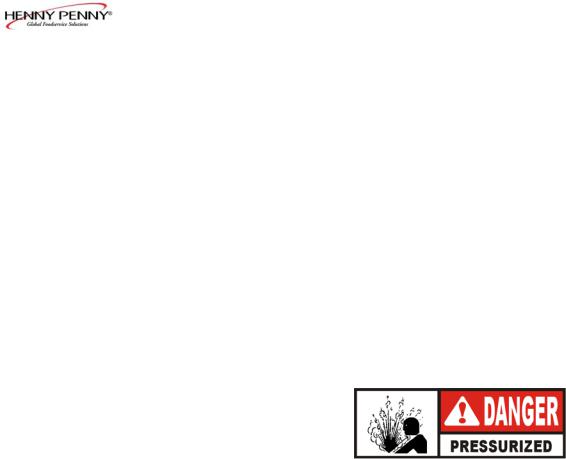
Safety Relief Valve |
AnASME approved spring-loaded valve set at 14.5 psi |
|
(999 mbar); in the event the operation valve becomes obstructed, |
|
this safety valve will release excess pressure, keeping the frypot |
|
chamber at 14.5 psi (999 mbar); if this occurs, turn the COOK/ |
|
PUMP switch to the OFF position to release all pressure from the |
|
frypot |
Safety Relief Valve Ring |
This ring is not to be pulled |
SEVERE BURNS FROM THE STEAM WILL RESULT.
803 |
3-1 |
Model 691
3-1. OPERATING CONTROLS
(Continued) |
|
Pressure Gauge |
Indicates the pressure inside the frypot |
Solenoid Valve |
An electromechanical device that causes pressure to be held in the |
|
frypot |
|
The valve closes at the beginning of the Cook Cycle and opens |
|
automatically at the end of the Cook Cycle; if this valve should |
|
become dirty or the Teflon seat nicked, pressure will not build up |
|
and it must be repaired per the Technical Manual maintenance |
|
procedures |
Drain Valve |
A two-way ball valve; it is normally in the closed position; turn the |
|
handle to drain the shortening from the frypot into the filter drain |
|
pan |
|
DO NOT OPEN THE DRAIN VALVE WHILE |
|
FRYPOT IS UNDER PRESSURE. HOT SHORTEN- |
|
ING WILL EXHAUST FROM THIS VALVE, AND |
|
SEVERE BURNS WILL RESULT. |
Drain Interlock Switch |
A microswitch that provides protection for the frypot in the event an |
|
operator inadvertently drains the shortening from the frypot while |
|
the main switch is in the COOK position; the switch is designed to |
|
automatically shut off the heat when the drain valve is opened |
Condensation Drain Pan |
A collection point for the condensation formed within the steam |
|
exhaust system; it must be removed and emptied periodically, |
|
usuallydaily |
Shortening Mixing System |
Ensures the shortening is properly mixed to prevent an accumulation |
|
of moisture, causing boiling action in the frypot; the filter pump is |
|
activated by the controls, at preset intervals, to mix the shortening |
Lid Latch |
A mechanical catch on the front of the lid which engages a bracket |
|
on the front of the pot; this device holds the lid down while the lid is |
|
being locked into place, but is not meant to hold pressure in the |
|
frypot |
3-2 |
803 |
 Loading...