

Page 1

July 2013
User’s Manual
EIB 741
EIB 742
External Interface Box
for Connecting
HEIDENHAIN Encoders
Page 2

2
DOCUMENTATION ................................................................................................................................ 5
FIRMWARE VERSION ............................................................................................................................ 5
CHANGE HISTORY ................................................................................................................................. 5
PART 1: FEATURES ................................................................................................................................ 6
1 GENERAL DESCRIPTION OF FUNCTION .......................................................................................... 6
2 CONFIGURATION OF THE ENCODER INPUTS ................................................................................. 7
2.1 Processing Incremental Signals ............................................................................................................................ 7
2.2 Analog Values of the 1 VPP Incremental Signals A and B: ................................................................................. 9
2.3 Dealing with Reference Marks ............................................................................................................................... 9
2.4 Monitoring the Reference Marks ......................................................................................................................... 10
2.5 Processing EnDat Signals .................................................................................................................................... 11
2.6 Auxiliary Axis ........................................................................................................................................................ 14
3 PROCESSING OF TRIGGER EVENTS .............................................................................................. 15
3.1 Trigger Inputs and Outputs ................................................................................................................................. 15
3.2 Logical Inputs and Outputs .................................................................................................................................. 16
3.3 Trigger Module ..................................................................................................................................................... 16
3.4 Interval Counter .................................................................................................................................................... 18
3.5 Maximum Trigger Rate ........................................................................................................................................ 18
3.6 Counter for Accepted Trigger Events.................................................................................................................. 18
4 TIMESTAMP ...................................................................................................................................... 19
5 STATUS WORD ................................................................................................................................. 19
6 ETHERNET INTERFACE .................................................................................................................... 22
7 OPERATING MODES ........................................................................................................................ 22
7.1 Configuration of Data Packets ............................................................................................................................. 22
7.2 "Polling" Operating Mode .................................................................................................................................... 24
7.3 "Soft Real-Time" Operating Mode ...................................................................................................................... 25
7.4 "Streaming" Operating Mode .............................................................................................................................. 26
7.5 "Recording" Operating Mode .............................................................................................................................. 27
8 FIRMWARE UPDATE ......................................................................................................................... 28
9 RESET ................................................................................................................................................ 28
PART 2: DRIVER SOFTWARE .............................................................................................................. 29
1 GENERAL INFORMATION ................................................................................................................ 29
2 INSTALLATION INSTRUCTIONS ..................................................................................................... 29
2.1 Windows ................................................................................................................................................................ 29
2.2 Linux ...................................................................................................................................................................... 29
3 OVERVIEW ........................................................................................................................................ 29
3.1 Establishing Communication ............................................................................................................................... 29
3.2 Configuration of Data Packets ............................................................................................................................. 29
3.3 Polling Mode ......................................................................................................................................................... 30
3.4 Soft Real-Time Mode ............................................................................................................................................ 30
3.5 Streaming Mode ................................................................................................................................................... 30
3.6 Recording Mode .................................................................................................................................................... 30
4 DATA TYPES ..................................................................................................................................... 31
4.1 Simple Data Types ................................................................................................................................................ 31
4.2 EnDat Additional Datum ...................................................................................................................................... 31
4.3 Information for TCP Connection .......................................................................................................................... 31
4.4 Configuration for Data Packet ............................................................................................................................. 31
5 PARAMETERS AND RETURN CODES ............................................................................................. 31
6 AUXILIARY FUNCTIONS .................................................................................................................. 32
6.1 Determining the IP Address ................................................................................................................................. 32
6.2 Changing the Position Data Format .................................................................................................................... 32
Page 3

3
7 DEVICE FUNCTIONS ......................................................................................................................... 33
7.1 Opening a Connection to the EIB 74x ................................................................................................................. 33
7.2 Closing the Connection to the EIB 74x ............................................................................................................... 34
7.3 Polling the Connection Status ............................................................................................................................. 34
7.4 Setting Up Timeout .............................................................................................................................................. 34
7.5 Reading Out the Number of Axes ....................................................................................................................... 35
7.6 Requesting Handle for Axis ................................................................................................................................. 35
7.7 Requesting IO Port Handle ................................................................................................................................... 35
7.8 Creating a Data Packet ......................................................................................................................................... 36
7.9 Configuring a Data Packet ................................................................................................................................... 36
7.10 Selecting the Operating Mode ............................................................................................................................ 37
7.11 Saving Network Parameters ................................................................................................................................ 37
7.12 Reading out the Network Parameters ................................................................................................................ 38
7.13 Saving the Host Name ......................................................................................................................................... 38
7.14 Reading out the Host Name ................................................................................................................................ 39
7.15 Reading out the Serial Number ........................................................................................................................... 39
7.16 Reading out the Device ID .................................................................................................................................... 39
7.17 Reading out the MAC Address ............................................................................................................................ 40
7.18 Reading out the Firmware Version Number ...................................................................................................... 40
7.19 Reading out the Boot Mode ................................................................................................................................. 41
7.20 Reading out the Update Status ........................................................................................................................... 41
7.21 Reading the Number of Open Connections ........................................................................................................ 41
7.22 Reading out the Connection Data ....................................................................................................................... 42
7.23 Terminating the Connection ................................................................................................................................ 42
7.24 Reading the Time Unit Timestamp ..................................................................................................................... 42
7.25 Setting the Timestamp Period Duration ............................................................................................................. 43
7.26 Resetting the Timestamp Counter ...................................................................................................................... 43
7.27 Reading the Timer-Trigger Time Unit ................................................................................................................. 43
7.28 Setting the Timer Trigger Period Duration ......................................................................................................... 43
7.29 Reading the Time Unit for the Delay Time at the Trigger Inputs ..................................................................... 44
7.30 Clearing the Trigger Counter ............................................................................................................................... 44
7.31 Software Trigger ................................................................................................................................................... 44
7.32 Selecting the Master Trigger Source .................................................................................................................. 45
7.33 Activating Trigger Sources .................................................................................................................................. 46
7.34 Configuring the Pulse Counter ............................................................................................................................ 47
7.35 Setting the Interpolation Factor for the Interval Counter ................................................................................. 48
7.36 Configuring the Interval Counter ........................................................................................................................ 49
7.37 Setting the Terminating Resistors ...................................................................................................................... 49
7.38 Reset ...................................................................................................................................................................... 50
7.39 Identifying the EIB 74x ......................................................................................................................................... 50
7.40 Transferring the Recording Data ......................................................................................................................... 51
7.41 Verifying the Recording Status ........................................................................................................................... 51
7.42 Reading the Recording Memory Size.................................................................................................................. 52
7.43 Checking the Streaming Status .......................................................................................................................... 52
7.44 Reading Data from the FIFO ................................................................................................................................ 53
7.45 Reading the Size of a FIFO Element .................................................................................................................... 53
7.46 Access to the Contents of a FIFO Element ......................................................................................................... 54
7.47 Reading and Converting Data from the FIFO ..................................................................................................... 55
7.48 Reading the Size of a FIFO Element Following Conversion .............................................................................. 55
7.49 Access to the Contents of a FIFO Element with Converted Data ..................................................................... 56
7.50 Reading the Number of Elements in the FIFO .................................................................................................... 56
7.51 Clearing the FIFO .................................................................................................................................................. 57
7.52 Setting the FIFO Size ............................................................................................................................................ 57
7.53 Reading the FIFO Size .......................................................................................................................................... 57
7.54 Activating the Callback Mechanism .................................................................................................................... 58
7.55 Selecting the Trigger Source for the Auxiliary Axis .......................................................................................... 59
7.56 Reading the Position of the Auxiliary Axis ......................................................................................................... 59
7.57 Reading Out the Data of the Auxiliary Axis ........................................................................................................ 60
7.58 Clearing the Counter of the Auxiliary Axis ......................................................................................................... 60
7.59 Acknowledging the Signal Errors of the Auxiliary Axis .................................................................................... 60
7.60 Acknowledging the Trigger Errors of the Auxiliary Axis ................................................................................... 61
7.61 Clearing the Status Bit for the Reference Mark of the Auxiliary Axis .............................................................. 61
7.62 Checking the Status of the Reference Run for the Auxiliary Axis .................................................................... 61
Page 4

4
7.63
Starting a Reference Run for the Auxiliary Axis ................................................................................................ 61
7.64 Stopping a Reference Run for the Auxiliary Axis ............................................................................................... 62
7.65 Configuring a Timestamp for the Auxiliary Axis ................................................................................................ 62
7.66 Setting the Trigger Edge for the Reference Pulse of the Auxiliary Axis .......................................................... 62
8 AXIS FUNCTIONS ............................................................................................................................. 63
8.1 Initializing the Axis ............................................................................................................................................... 63
8.2 Selecting the Trigger Source for the Axis .......................................................................................................... 66
8.3 Setting the Trigger Edge for the Reference Pulse ............................................................................................. 66
8.4 Clearing the Counter ............................................................................................................................................ 67
8.5 Interrogating a Position ....................................................................................................................................... 67
8.6 Reading out Data for a Channel .......................................................................................................................... 68
8.7 Acknowledging the Power Supply Error ............................................................................................................ 68
8.8 Acknowledging the Trigger Error ........................................................................................................................ 69
8.9 Acknowledging the Signal Error ......................................................................................................................... 69
8.10 Clearing EnDat Error Bits ..................................................................................................................................... 69
8.11 Clearing Status Bits for Reference Marks ........................................................................................................... 70
8.12 Clearing Status Bits for Distance-Coded Reference Marks ............................................................................... 70
8.13 Starting the Reference Run .................................................................................................................................. 70
8.14 Stopping the Reference Run ................................................................................................................................ 71
8.15 Verifying the Status of the Reference Run ......................................................................................................... 71
8.16 Activating the Monitoring of the Reference Marks ........................................................................................... 71
8.17 EnDat 2.1: Reading the Position .......................................................................................................................... 72
8.18 EnDat 2.1: Selecting the Memory Area ............................................................................................................... 72
8.19 EnDat 2.1: Sending Data ...................................................................................................................................... 73
8.20 EnDat 2.1: Receiving Data .................................................................................................................................... 73
8.21 EnDat 2.1: Resetting the Encoder ........................................................................................................................ 74
8.22 EnDat 2.1: Reading the Test Value ...................................................................................................................... 74
8.23 EnDat 2.1: Sending Test Command to Encoder ................................................................................................. 75
8.24 EnDat 2.2: Reading the Position and Additional Datum .................................................................................... 75
8.25 EnDat 2.2: Reading the Position and Additional Datum and Selecting the Memory Area ............................. 76
8.26 EnDat 2.2: Reading the Position and Additional Datum and Sending Data .................................................... 76
8.27 EnDat 2.2: Reading the Position and Additional Datum and Receiving Data .................................................. 77
8.28 EnDat 2.2: Reading the Position and Additional Datum and Sending the Test Command ............................ 77
8.29 EnDat 2.2: Reading the Position and Additional Datum and Transmitting the Error Reset ........................... 78
8.30 EnDat 2.2: Selecting the Additional Datum ........................................................................................................ 79
8.31 EnDat 2.2: Selecting the Sequence for Additional Datum ................................................................................ 80
8.32 Reading Absolute and Incremental Position Values Simultaneously .............................................................. 81
8.33 Setting the Power Supply for Encoders ............................................................................................................. 81
8.34 Reading the Power Supply Status for Encoders ................................................................................................ 82
8.35 Configuring the Timestamp ................................................................................................................................. 82
9 IO FUNCTIONS .................................................................................................................................. 83
9.1 Configuring the Input Port ................................................................................................................................... 83
9.2 Configuring the Output Port ................................................................................................................................ 84
9.3 Selecting the Trigger Source for the Trigger Output ........................................................................................ 84
9.4 Setting the Delay Time for the Trigger Input ..................................................................................................... 85
9.5 Reading Out a Logical Port .................................................................................................................................. 85
9.6 Setting the Logical Output Port .......................................................................................................................... 86
9.7 Reading the Configuration Data for an Input ..................................................................................................... 86
9.8 Reading the Configuration Data for an Output .................................................................................................. 87
10 GENERAL FUNCTIONS ................................................................................................................... 88
10.1 Reading the Driver ID Number ............................................................................................................................ 88
10.2 Converting an Error Message into Text .............................................................................................................. 88
Page 5

5
Documentation
The documentation for the EIB 741 and EIB 742, hereafter referred to as EIB 74x, comprises the following documents:
• Commissioning Instructions:
- Documents required for commissioning, as well as technical specifications.
• User's Manual:
- Description of features on the EIB 74x.
- Description of the installation and function calls of the driver software.
Firmware version
This document describes Firmware version: 633281-10
Change history
Changes from the previous versions are listed in the change history.
The document on change history is on the CD in the subdirectory EIB_74x/doc. Please read this document, in particular the
notes on new, changed or obsolete function calls.
Page 6

6
Part 1: Features
1 General Description of Function
The EIB 74x is an external interface box for precise position measurement. It is ideal for inspection stations and multipoint
inspection apparatuses as well as for mobile data acquisition, such as in machine inspection and calibration.
The EIB 74x is ideal for applications requiring high-resolution encoder signals and fast data logging. Ethernet transmission
also enables you to use switches or hubs for connecting more than one EIB 74x.
A maximum of four HEIDENHAIN encoders, either with sinusoidal incremental signals (1 V
PP
) or with EnDat interfaces
(EnDat 2.1 and EnDat 2.2) can be connected to the EIB 74x.
The EIB 74x subdivides the periods of the incremental signals 4096-fold for measured-value generation. The deviations
within one signal period are automatically reduced by adjusting the sinusoidal incremental signals (signal compensation).
The integrated measured-value memory enables the EIB 74x to save up to 250,000 measured values per axis in "recording
mode." Internal or external triggers can be used for axis-specific storage of the measured values. A standard Ethernet
interface using TCP or UDP communication is available for data output. This permits direct connection to a PC, laptop or
industrial PC.
The method of measured value transmission can be set via the operating mode. Driver software for Windows, Linux and
LabVIEW is included in the items supplied, in order to process the measured values on the PC. The driver software facilitates
programming of customer applications. It also contains program examples demonstrating the performance range of the
EIB 74x.
Basic circuit diagram
Encoder inputs:
A maximum of four HEIDENHAIN encoders with the following interfaces (freely programmable) can be connected to the
EIB 74x:
• Incremental signals 1 V
PP
• EnDat 2.1
• EnDat 2.2
• Incremental signals 1 V
PP
(upon request)
The power supply to the encoders is provided by the EIB 74x and is protected by a resettable overload cutout.
For technical specifications, see "Commissioning Instructions."
Page 7

7
2 Configuration of the Encoder Inputs
After power-up, the power supply to the encoders is activated. The other parameters for operating the encoder input must
be configured by initialization.
• Interface type
• Bandwidth for the 1 V
PP
input signals
• Signal compensation
• Processing the reference marks
• Processing the homing/limit signals
These settings can be changed via software.
The interface for the encoder input can be operated in incremental or EnDat mode. In EnDat mode, the incremental block
can also be operated if, in addition to EnDat, the encoder also supports the 1 V
PP
interface.
2.1 Processing Incremental Signals
The EIB 74x subdivides the periods of the incremental signals 4096-fold for position value generation (12 bits). The period
counter has a width of 32 bits. The counter value is increased or decreased by the value "1" with each signal period of the
connected encoder.
The deviations within one signal period are automatically reduced by adjusting the sinusoidal incremental signals (signal
compensation). Compensation of the incremental encoder signals and the terminating resistor can be activated or
deactivated by software.
The 44-bit wide position information at the time of the trigger event is formed from the interpolation value (12 bits) and the
value of the period counter (32 bits). The position information is saved to a 48-bit wide register (see table). The period
counter is mapped in the two's complement notation; bits 43 to 47 represent the sign.
Depending on the encoder type (linear or rotary), the higher-level customer software application can use this value to
calculate the angle and length, respectively.
The period counter overflows according to the two's complement notation at the position: 0x07FF FFFF FFFF (maximum
positive) 0xF800 0000 0000 (maximum negative). This overflow does not affect the functionality of the period counter or
the interpolator. The overflow, however, must be handled by the higher-level customer software application.
Bit no. Width (bits) Contents
0..11 12 Interpolation value
12..43 32 Period counter (bit 43 = sign)
44..47 4 Value identical to bit 43
Page 8

8
Block diagram
Interpolation value
At the time of the trigger event, the incremental signals are scanned and used to calculate a 12-bit wide interpolation value
(not with the EnDat interface). The correlation between interpolation value and incremental signals is derived as follows:
Setting options:
Terminating resistor for the incremental signals
The 120 ohm terminating resistor for the 1 V
PP
incremental signals can be activated or deactivated (for all channels
simultaneously; default: resistors activated) by software.
Bandwidth setting of the incremental signals
The bandwidth of the encoder's incremental signals can be toggled by software. The high bandwidth (500 kHz) should be set
as default.
The low bandwidth (33 kHz) should only be selected for special applications.
Signal compensation
Compensation of the incremental encoder signals can be activated or deactivated by software.
Page 9
9
2.2 Analog Values of the 1 V
PP
Incremental Signals A and B:
The transmitted values correspond to the values of the AD converter at the time of the trigger event.
Bit no. Width (bits) Contents
0..11 12 12-bit AD converter value
12..15 4 Reserved
Value (HEX) Incremental signal value
000 Negative maximum
800 Zero
FFF Positive maximum
2.3 Dealing with Reference Marks
With incremental encoders, the reference mark/marks is/are used to generate an absolute reference for the incremental
signals.
For encoders with one reference mark, this mark has an explicit reference to a specific signal period. This signal period can
be used as a reference to generate absolute position values. Traversing the reference mark does not affect the period
counter or the interpolation value. The period counter value valid at the time of traversing is simply saved in a register for the
reference position. This value can be used in the customer software application to calculate absolute position values.
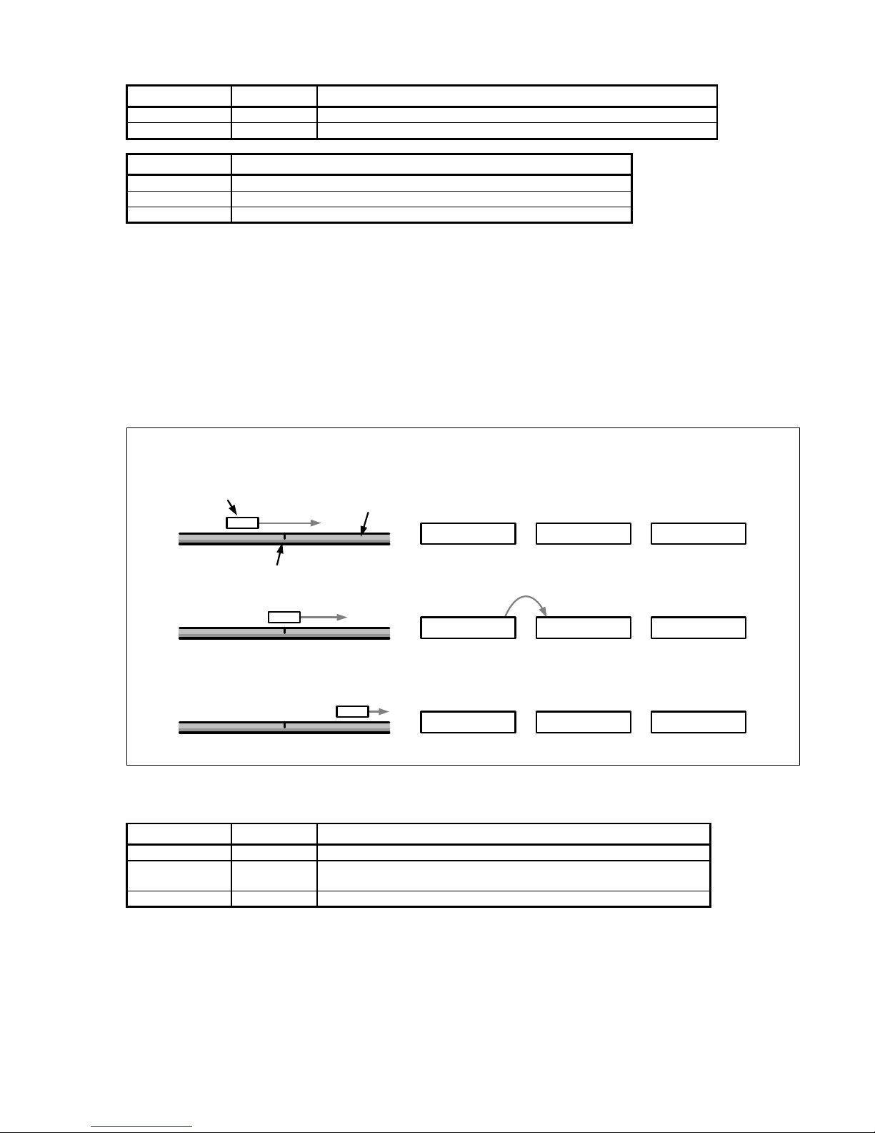
The figure below shows the general process of determining a reference position. The displayed values are only given as an
example. To improve clarity, only a section of the position-value register is shown.
Linear scale
Scanning head
Reference mark
Motion
0x2A733D1
Actual position
value
Stored reference
position
Absolute position
(calculated by the
application)
0x318B000
0x36D9884
0x318B000
0x318B000
0x0000000
0x054E884
-
=
-
-
=
=
latch
Reference mark detected
Register contents, reference position
Bit no. Width (bits) Contents
0..11 12 Always 0
12..43 32
Reference position (value of the period counter when the reference
mark is detected; bit 43 = algebraic sign)
44..47 4 Value identical to bit 43
Automatic saving of the reference position must be activated by software. After this command, the EIB 74x waits for the
next reference mark and then saves the reference position.
You must activate this feature again if renewed saving is desired.
Normally, the reference position register is transmitted together with the position register and the status word in a shared
position data packet after the next trigger event. During this process, the EIB 74x transmits two reference positions and,
where applicable, the coded reference value:
• For encoders with one reference mark, reference position 1 is normally used.
• For encoders with distance-coded reference marks, either both register values are used or the coded reference
value is used depending on the evaluation method.
Page 10

10
Distance-coded reference marks
With distance-coded encoders, the reference for generating absolute position values from the counter values is obtained
through the distance of two traversed (adjacent) reference marks.
For this purpose, the period counter value is saved twice, once each time a reference mark is traversed. The coded
reference value is generated from the distance of the (adjacent) reference marks, and in doing so the reference for
generating absolute position values is also created.
When the absolute position value is calculated by the customer software application, this value is treated exactly the same
as a saved reference position value in the case of encoders with one reference mark (see drawing). The coded reference
value thus corresponds to the offset between the absolute position value and the generated (incremental) position value.
There are various procedures for generating the coded reference value:
Method 1: (recommended method)
The axis is initialized as an incremental system with distance-coded reference marks. During this process, further typedependent information about the measuring system is transferred to the EIB 74x. Once the reference positions have been
saved successfully, the EIB 74x uses this information to automatically calculate the coded reference value. The saving
process is started by software command (for two reference marks). After the second reference mark has been traversed,
the EIB 74x automatically calculates the coded reference value and transfers it to the customer software application.
Method 2: (especially for applications with an extremely low traversing speed)
The axis is initialized as an incremental system with a simple reference mark. The customer software application sends the
appropriate software command for saving the reference position (one reference mark). Each time the reference position has
been saved successfully, the save process is activated again. This procedure must be repeated until two different reference
positions have been measured. The customer software application can then calculate the coded reference value and hence
the absolute position from these two values. It must be guaranteed that the customer software application can complete this
procedure quickly and sufficiently, otherwise reference marks could be lost, resulting in an incorrect calculation of the
absolute position.
Method 3:
The axis is initialized as an incremental system with a simple reference mark. The customer software application sends the
appropriate software command for saving two reference positions. After both reference positions have been saved
successfully (both reference position registers are used), the customer software application can calculate the coded
reference value and hence the absolute position from these two values.
2.4 Monitoring the Reference Marks
The reference marks of an encoder can be monitored automatically. For this purpose, the reference position is saved and
checked continuously. This results in the reference-position output being updated with each reference mark, and therefore
can lead to a change in the reference position. The check varies slightly depending on the encoder, as described below. If an
error occurs, a bit is set in the status word for the position.
Encoders with one reference mark:
For linear encoders with one reference mark, the position value at the reference mark must always be the same. The
reference position is saved continuously and compared to the old value.
For rotary encoders with one reference mark, the position value at the reference mark may change if the encoder is moved
in the same direction over one revolution. Two successively saved reference positions must be the same or may differ by
the number of signal periods per revolution. The transmitted data packet always contains the current reference position.
Encoders with distance-coded reference marks:
For encoders with distance-coded reference marks, the coded reference position is recalculated continuously. The
calculation always uses two adjacent reference positions as illustrated in the figure below. The transmitted data packet
always contains the currently calculated reference position.
Page 11

11
For linear encoders, the calculated reference position must always be the same. For rotary encoders, the calculated
reference position may differ by the number of signal periods per revolution. If the same reference mark is traversed twice
before and after a change in direction, the distance-coded reference mark cannot be calculated. No check takes place in this
case. This must be taken into account especially for very small movements across a reference mark.
No reference run can be performed while monitoring of the reference marks is active, because this could lead to an incorrect
error message in the monitoring process. The following sequence is recommended:
• Configuring the axes
• Performing the reference run
• Activating the monitoring of the reference marks
2.5 Processing EnDat Signals
HEIDENHAIN absolute encoders are available with EnDat 2.1 or EnDat 2.2 interface. Especially in the case of EnDat 2.1
encoders, 1 V
PP
incremental signals are transmitted along with the EnDat signals. The EIB 74x is able to process all EnDat
encoders with EnDat 2.1 or EnDat 2.2 interface both serially and also with 1 V
PP
incremental signals.
The EnDat Master is set up individually when the axis is initialized:
• EnDat 2.1 or EnDat 2.2 communication can be set.
• The clock frequency for EnDat communication can be set.
• Delay compensation (EnDat 2.2) can be activated or deactivated.
• The recovery time I can be set if the encoder supports it.
• The monitoring of the calculation time can be set.
Notes on EnDat 01:
• If EnDat position polls and 1 V
PP
incremental signals are used at the same time, only EnDat 2.1 mode commands
can be sent to the encoder (axis must be configured for EnDat 01).
• The EnDat position can be imported only by a software command. Hence, the EnDat position and incremental
position must be imported once (special command). Then an incremental position can be cyclically transferred.
Position value register
The position register maps the position transmitted via the EnDat interface at the time of the trigger event. The position
register for the EnDat position is 48-bits wide. The number of bits used for the position value depends on the connected
EnDat encoder; the uppermost, unused bits must be masked out. See the encoder specifications for more detailed
information.
Bit no. Width (bits) Contents
0..47 48 EnDat position value
Page 12

12
EnDat clock frequency
The EnDat clock frequency can be set by a software command. The clock frequency can be set at specific intervals between
100 kHz and 6.66 MHz. The maximum permitted frequency is dependent on both the cable length between encoder and
EIB 74x and also on whether delay compensation is activated.
Clock frequency
parameter
Clock frequency Comment
100000 100 kHz
300000 300 kHz Default with EnDat 2.1
500000 500 kHz
1000000 1 MHz
2000000 2 MHz Default with EnDat 2.2
4000000 4 MHz
5000000 5 MHz
6666666 6.66 MHz
Delay compensation
Delay compensation for the EnDat transmission can be activated or deactivated during axis configuration. Delay
compensation is not approved by HEIDENHAIN for EnDat 2.1 encoders (exception: encoders with the ordering designation
EnDat21). Delay compensation is approved by HEIDENHAIN for EnDat 2.2 encoders. This results in the following
dependency of the maximum permitted EnDat clock frequency.
EnDat clock frequency
Cable length in meters
Without delay compensation With delay compensation
100 kHz 150 100
300 kHz 150 100
500 kHz 100 100
1 MHz 55 100
2 MHz 10 100
4 MHz --- 50
5 MHz --- 40
6.66 MHz --- 25
Recovery time I
The recovery time I can be set for EnDat 2.2 encoders (ordering designation EnDat02 or EnDat22). Here there are two
options—"long" (10 µs < t
m
< 30 µs) and "short" (1.25 µs < tm < 3.75 µs). For EnDat 2.1 encoders, the long recovery time I is
always used.
Notes on setting the short recovery time I:
• The default setting is "long."
• The short setting is chosen in order to attain shorter cycle times during EnDat transmission.
• For the short setting, the EnDat clock frequency must be set to > 1 MHz at the same time.
Calculation time
The calculation time indicates the time for position formation in the encoder and therefore affects the duration of the position
request. In order to monitor the communication a timeout is generated if the position request exceeds a certain duration.
This is displayed in the status word as an error. If the calculation time was set too short, this error message can appear even
though the encoder transmitted the data correctly. Conversely, an excessively long calculation time can cause an undesired
delay in the error message. At high trigger rates, in particular, the error message can be offset by several samples.
The calculation time can be set to depend on the connected encoder. Two options are supported:
Long The calculation time of the encoder is < 1 ms
Short The calculation time of the encoder is < 15 µs
Notes:
• The default setting is "long."
• For the short setting, the EnDat clock frequency must be set to > 1 MHz at the same time.
Page 13

13
EnDat 2.2 additional data
The EnDat 2.2 additional data can be transmitted in various ways in the Soft Real-Time, Streaming, and Recording operating
modes.
1) No additional datum
A position request is started with each trigger event. Additional data is not transmitted.
2) Fixed additional data
Besides the position value, with each trigger event one piece of fixed information is sent as additional datum 1 and additional
datum 2. This has to be set before activation of the corresponding operating mode. It can only be changed in the Polling
mode of operation. It is also possible to transmit only additional datum 1 or additional datum 2.
3) Variable additional data
The additional data is switched in cycles. The EIB 74x features a ring buffer with 10 entries for setting the additional data,
which is executed cyclically. The position value and the additional data 1 and 2 are transmitted with each trigger event. In
addition, the EnDat 2.2 transmission supplement is transmitted, over which a new additional datum is selected based on the
data in the ring buffer. The additional data 1 and 2 can be mixed in the ring buffer. Only one of the two additional data can be
switched over per position request.
Processing additional incremental signals with EnDat
If, with EnDat encoders, the incremental signals are used for position formation, an absolute reference can be created by
saving the EnDat position and the incremental position simultaneously. To do this, a special command is sent to the EIB 74x
via the customer software application, which then generates an internal trigger signal. This trigger signal initiates
simultaneous position determination via the EnDat interface and via the incremental signals. Both positions are transmitted
to the customer software application as a return code.
Note:
The interpolation zero points for the incremental signals and the EnDat position are different and must also be taken into
account by the customer software application.
Furthermore, any differing resolution between EnDat and incremental position must also be taken into account.
Incremental signals: see "Processing incremental signals" section for interpolation zero point
EnDat Position: see graphic for interpolation zero point
EnDat master
Page 14

14
2.6 Auxiliary Axis
The auxiliary axis is coupled to axis 1 and can be used for encoders with 1 Vpp interface. The signals of axis 1 are
interpolated and forwarded to a position counter. The interpolation factor can be set at specific intervals. Edge evaluation (1fold, 2-fold or 4-fold) can also be selected. The maximum permissible input frequency of the encoder signals for the
interpolator depends on the interpolation factor and is shown in the table below. In order not to limit the input frequency
unnecessarily, the edge evaluation should be set to 4-fold (4x), and therefore a low interpolation factor should be selected.
For example, a 5-fold interpolation factor with 4-fold edge evaluation results in the same increment as a 20-fold interpolation
factor with 1-fold edge evaluation, but the maximum permissible input frequency is higher.
Linear encoder:
µm
=
µm
∙
Rotary encoder:
1°
=
360°
∙
Interpolation factor Max. input frequency in kHz
1-fold 500
2-fold 500
4-fold 500
5-fold 500
10-fold 400
20-fold 200
25-fold 160
50-fold 80
100-fold 40
Besides the position value, a timestamp and a reference position are available to the auxiliary axis. The status word for the
auxiliary axis contains status and error messages. Both the position value and the reference position are 32-bit values. The
number of counting steps per signal period of the encoder depends on the interpolation factor for the auxiliary axis. The
position value is represented as a two's complement number. According to this, it overflows at the position: 0x7FFF FFFF
(maximum positive) 0x8000 0000 (maximum negative). Any overflow must be handled by the higher-level customer
software application.
Bit no. Width (bits) Contents
0..31 32 Position value of the auxiliary axis (bit 31 = sign)
Page 15
15
3 Processing of Trigger Events
Position value determination inside the EIB 74x is initiated via a so-called trigger event. The EIB 74x supports the following
trigger sources:
• 4 external trigger inputs
• Internal periodic trigger source, timer-controlled
• Software command
• Reference pulse of the encoders
• Position trigger (interval counter)
The trigger source must be set by software command for each axis; only one trigger source per axis can be active at the
same time. However, it is possible to activate different trigger sources for different axes. Also, one trigger source must be
defined as the master trigger source that defines the time of data transmission. For all axes triggered by the master trigger
source, a new position is transmitted in each data packet. For all other axes, a valid position is transmitted only if a trigger
event also occurred for the respective axis. Otherwise, the position value is marked as invalid.
Not all trigger interface options are supported in all operating modes; see "Operating Modes" section for details.
3.1 Trigger Inputs and Outputs
Four trigger inputs and/or outputs are supported. For technical specifications on the trigger input, see "Commissioning
Instructions."
Trigger inputs
Synchronize the position requests on external events; please also note the information provided in Chapter 3.5.
The 120 ohm terminating resistor can be activated or deactivated by configuration.
Trigger outputs
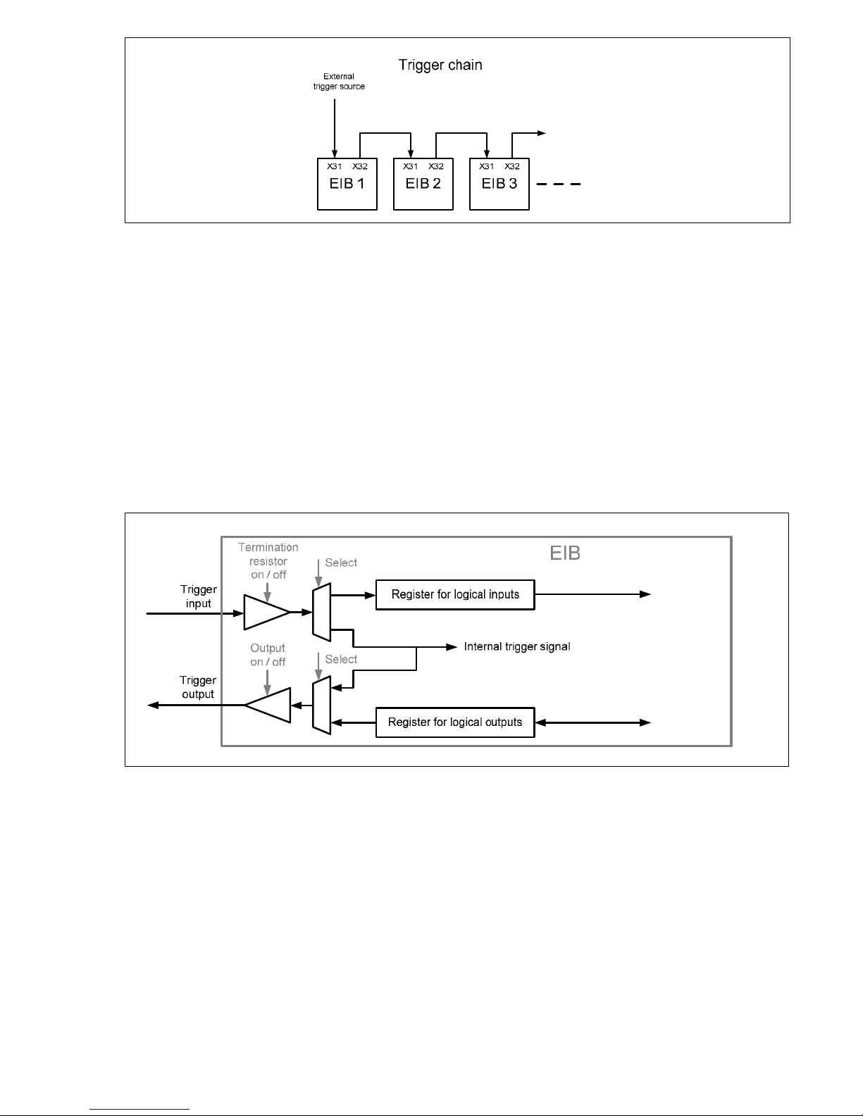
The trigger outputs forward trigger events, e.g. to other EIB 74x units. This permits the generation of a trigger chain, which
synchronizes multiple EIB 74x units with an external trigger event. The various EIB 74x units must be configured separately
by software commands. The position data is sent via the respective Ethernet connection. To generate a trigger chain, the
following connection between the EIB 74x units must be used:
• Trigger Out + Trigger In +
• Trigger Out – Trigger In –
• GND to GND
A pulse at the trigger output is 2 µs long and is generated synchronously with the system clock of the EIB 74x. The trigger
event corresponds to the rising edge of the pulse. If a signal is forwarded from the trigger input to the output, it is affected
by jitter due to the synchronization with the system clock. In order to avoid this jitter, it is possible to switch the signal at the
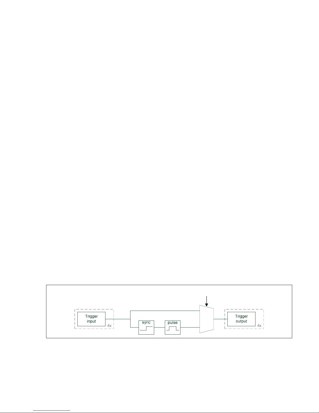
trigger input directly to the corresponding trigger output.
The trigger signals can be fed through from the input to the output separately for each channel. Input 1 can be connected to
output 1, and so on. The trigger input and the corresponding output are shown in the figure below.
Note:
The differential signals "Trigger Out +" and Trigger Out –" can be swapped in order to change the polarity of the signal at the
trigger output. Accordingly, the output "Trigger Out –" must be used for single-ended signals (see instructions for
installation/commissioning).
config
Page 16
16
Configuring the trigger inputs and outputs as logical inputs and outputs
The trigger inputs/outputs can also be used as logical inputs/outputs. Trigger inputs and/or outputs are set by default. The
ports can be individually configured as logical inputs and outputs or as trigger inputs and outputs by a software command. It
is not possible to use them simultaneously as trigger inputs/outputs and logical inputs/outputs.
3.2 Logical Inputs and Outputs
Logical inputs
Each trigger input can be individually converted to a logical input. The level of the corresponding input can be read by a
software command. The 120 ohm terminating resistor can also be activated or deactivated in this mode by configuration.
Logical outputs
Each trigger output can be individually converted to a logical output. The output level can also be read back. The outputs can
be individually activated or deactivated, irrespective of the configuration.
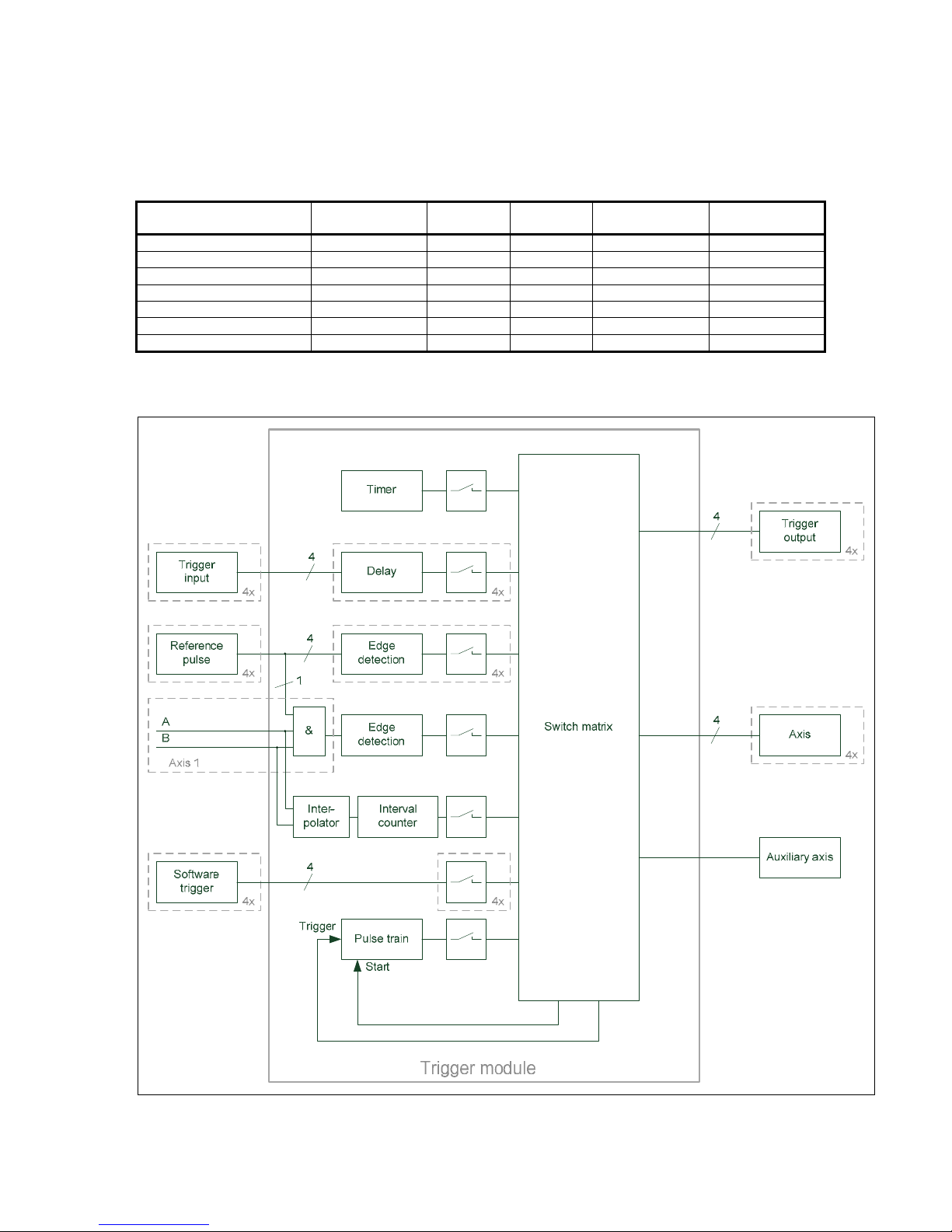
The graphic below shows the trigger input and output options at a glance. Only one channel is shown.
3.3 Trigger Module
The trigger module enables you to select and control the trigger sources. Furthermore, it generates internal trigger signals.
You can delay external trigger signals; the delay time can be set for each input separately. The reference pulse of an encoder
with 1 Vpp interface can be used for the associated axis as a trigger source. In addition, the reference pulse of axis 1 is gated
with the signals A and B of axis 1 by logic AND, and can be used as a trigger signal for any axes. The active edge of the
reference signal can be set in each case. If the reference pulse is selected as the trigger source for more than one axis, each
axis is triggered with its own reference pulse. If the reference pulse is also selected as the master trigger source in this
case, a reference pulse must occur on each axis before transmitting the data packet. Furthermore, there are four freely
assignable channels for software triggers.
The interval counter generates trigger signals depending on the position of the encoder on axis 1. A signal period of the
encoder can be divided into several counting steps via an adjustable interpolator. The triggering occurs either at a certain
position or at equidistant intervals.
Page 17
17
The pulse counter is not a separate trigger source; it allows you to limit the number of trigger pulses of other sources. A
selectable trigger source can supply pulses that are disabled until the gate is opened by the start signal. All trigger pulses are
then counted, and the gate is closed again after a selectable number of pulses. Besides, it is possible to reload the counter
while the gate is open. The number of trigger pulses can be increased in this way.
The switch matrix makes it possible to connect the trigger sources individually to the sinks, such as trigger outputs or axes.
However, not all sources can be connected to all sinks. The following table provides an overview of the possible
combinations: Only one trigger source is permissible per sink. For the pulse counter, there is a trigger signal whose trigger
pulses are controlled via the internal gate. The start signal opens the gate for the trigger pulses.
Trigger source Trigger output Axis
Auxiliary
axis
Pulse-counter
trigger
Pulse-counter
start
Trigger input x x x x x
Reference pulse – x x x x
Masked reference pulse x x x x x
Interval counter x x x x x
Pulse counter x x x – –
Software trigger x x x – x
Timer x x x x –
All trigger sources can be deactivated separately. This makes it possible to first configure the EIB 74x and then enable the
trigger sources. Any combination of trigger sources can be enabled or disabled at the same time.
Page 18

18
3.4 Interval Counter
The interval counter permits position-dependent triggering in connection with an incremental encoder on axis 1. The encoder
signal can be interpolated (see "Auxiliary Axis" chapter).
The triggering occurs at a certain position, or equidistant trigger pulses with an adjustable position interval are generated.
Output of the trigger pulses starts after an adjustable start position has been traversed, and is then continued at the position
interval in both counting directions. The position interval ΔX must be specified in counting steps (for calculating the
increment, see "Auxiliary Axis" chapter).
Hysteresis prevents multiple triggering, in particular if a high interpolation factor is used for the encoder signal. After a trigger
pulse has been generated at a position, the value of the position counter must change by +H or ---H before a new trigger
pulse is generated at the same position.
3.5 Maximum Trigger Rate
The maximum trigger rate of the EIB 74x depends on the set operating mode ("Polling" mode being an exception):
• Soft Real-Time mode: Max. 10 kHz
• Recording mode: Max. 50 kHz
• Streaming mode: Max. 50 kHz
Note:
In Streaming mode the data rate is additionally limited to 1 200 000 bytes/second. The data rate is product of the size of the
data packet and the trigger rate.
Byte
∙
Hz
≤ 1.200.000
Here it must be ensured that the data rate is not limited by the host on which the data are subsequently processed.
A certain interval, which the EIB 74x requires for the position calculation, must be respected between two trigger events. If
this interval is not respected, i.e. the trigger rate is too high, trigger events cannot be accepted by the EIB 74x, and therefore
are lost (lost trigger). This is detected by the EIB 74x and displayed in the status word of the position data packet by the "lost
trigger" bit. This bit is set at "1" until actively reset by the customer software application using a clear command.
The values mentioned above apply if incremental signals are used. If the EnDat interface is used, the EnDat transmission
time must be observed.
Caution:
If the maximum trigger rate is grossly exceeded (e.g. incorrect parameterization or too many events at the external trigger
input), this may result in the EIB no longer reacting to external commands so that it cannot be addressed until a hard reset.
3.6 Counter for Accepted Trigger Events
In addition to monitoring for lost triggers, the EIB 74x has, for further error detection, a counter that is incremented by each
incoming and accepted trigger event of the master trigger source. A trigger event is accepted if the above-mentioned interval
is maintained. Trigger events that result in lost triggers are not counted. The counter value is transferred in the position data
packet and can be monitored for continuity. This makes it possible to detect lost position data packets.
ΔX
ΔX
Page 19

19
4 Timestamp
The "timestamp" function is also used to monitor data flow. The timestamp counter is a free-running timer with a freely
programmable time interval. Each trigger event that results in a position value determination also causes the current timer
value to be saved to the timestamp register. When the timestamp function is activated, the contents of this register are
transmitted with the position data packet. This enables the customer software application to check whether the latch time of
each individual position value corresponds to the expected value. In the case of applications that do not have a periodic
trigger, the time of the trigger event can be transmitted with this register.
Note:
The time interval of the counter timestamp is a multiple of the internal system clock in the EIB 74x. Before the timestamp
function can be used, the time interval has to be set by a software command. The "clock ticks per µs" value must first be
read and the required time interval set in dependence of this value. This is necessary to keep the software compatibility
independent of various settings for the system clock.
Note:
The following data must be transferred to the function to ensure that the value for a period (e.g. for the “period” parameter
of the “EIB7SetTimestampPeriod” function call) is correctly calculated:
period = Time interval in µs * clock ticks per µs
The value for “clock ticks per µs” can be read out using the EIB7GetTimerTriggerTicks or EIB7GetTimestampTicks function,
for example.
This note applies to the function call in Chapter 7.25, as well as for the calls in Chapter 7.28 (please also note Chapter 3.5)
and Chapter 9.4.
5 Status Word
The status word must be interpreted depending on the poll type:
• Incremental position data
• EnDat position data
• Polling of EnDat additional data
The status word is transmitted separately for each encoder channel and does not depend on which operating mode is set.
Bit no. Incremental position EnDat position EnDat additional datum Auxiliary axis
0 1 = Valid position 1 = Valid position 1 = Valid additional datum 1 = Valid position
1 1 = Signal amplitude error 1 = CRC error 1 = CRC error 1 = Signal amplitude error
2 Reserved Reserved Reserved Reserved
3 1 = Frequency exceeded Reserved Reserved 1 = Frequency exceeded
4
1 = Encoder power supply
error
1 = Encoder power supply
error
Reserved
1 = Encoder power supply
error
5 1 = Fan error 1 = Fan error Contents I0 1 = Fan error
6 Reserved Reserved Contents I1 Reserved
7 1 = Lost trigger 1 = Lost trigger Contents I2 1 = Lost trigger
8
1 = Reference position 1
saved
1 = EnDat error message 1 Contents I3
1 = Reference position
saved
9
1 = Reference position 2
saved
1 = EnDat error message 2 Contents I4 Reserved
10
1 = Coded reference value
for distance-coded
reference marks is valid
Reserved EnDat busy bit Reserved
11
1 = Error when calculating
the coded reference value
for distance-coded
reference marks. Error while
monitoring the reference
marks
Reserved EnDat RM Bit Reserved
12 1 = Homing signal active Reserved EnDat WRN bit Reserved
13 1 = Limit signal active Reserved Reserved Reserved
14 Reserved Reserved Reserved Reserved
15 Reserved Reserved Reserved Reserved
Page 20

20
Notes on the error bits
Name Meaning
Valid position
1 No error occurred
This bit indicates whether the transmitted position is valid or not
Valid additional datum
1 EnDat additional datum was received
Otherwise, no additional datum has been selected or received
Signal amplitude error
1 Signal amplitude of 1 V
PP
incremental signals is and/or was too low
(once or repeatedly since this error message was last cleared)
Frequency exceeded
1 Excess input signal frequency has been detected
(once or repeatedly since this error message was last cleared)
CRC error 1 CRC error during EnDat data transmission
Encoder power supply error
1 Power supply to the encoder was switched off automatically. (overcurrent
fuse has tripped)
Fan error 1 The EIB 74x fan has malfunctioned
Lost trigger See "Maximum trigger rate" section
Reference position 1 saved
1 Reference position 1 was saved
(since the last corresponding software command)
Reference position 2 saved
1 Reference position 2 was saved
(since the last corresponding software command)
Coded reference value for distancecoded reference marks is valid
1 Coded reference value for distance-coded reference marks was calculated
successfully (since the last corresponding software command)
Error when calculating the coded
reference value for distance-coded
reference marks
1 Error when calculating the coded reference value; must be reset explicitly. An
error was detected during automatic monitoring of the reference marks. The error
must be cleared explicitly.
Homing signal 1 The homing signal (L1) is active at the time of the position request
Limit signal 1 The limit signal (L2) is active at the time of the position request
EnDat error message 1 1 Error message 1 active
EnDat error message 2 1 Error message 2 active
EnDat Busy bit 1 Busy bit is set
EnDat RM bit 1 RM (reference mark) bit is set
EnDat WRN bit 1 WRN (warning) bit is set
Contents I0 to I4
These five bits define the contents of the received additional datum. The customer
software application requires this information to interpret the data.
The error bits are not reset automatically. They have to be reset by a software command from a customer software
application. If an error is not reset, it will be re-transmitted with every subsequent position data packet.
With incremental encoders, an error in the position data packet indicates that the position is no longer valid and has lost any
reference to reference marks or other measuring channels.
The occurrence of one error can initiate others. An error in the power supply to the encoder will initiate other errors. Any
error in the power supply must therefore be reset first. Once the power supply is stable (delay of approx. 1.5 seconds), the
other errors must be reset.
Page 21

21
Lost trigger
The "lost trigger" bit indicates that at least one trigger event was processed incorrectly because the period between two
trigger events was too short. The "lost trigger" bit can also occur if malfunctions superimpose the trigger line or EMC
influences have a negative effect on the transmission. A "lost trigger" does not mean that the position values are false. It
merely indicates that trigger events were unable to be processed correctly. The reset must also be done actively by a
software command.
Reference position saved
The two "reference position 1 (2) saved" bits indicate that a valid reference mark has been detected and saved. This means
the corresponding reference position in the position data packet is valid.
Coded reference value for distance-coded reference marks is valid
This bit is reset by sending the corresponding software command for saving reference positions. After the coded reference
value has been calculated successfully, this bit is set to active. This means that the "coded reference value for distancecoded reference marks" transmitted in the position data packet can be used to calculate the absolute position.
Error in reference position for distance-coded reference marks
This bit is set if an error has occurred while the coded reference value for distance-coded reference marks is being
calculated. One possible reason is that during the reference run, a change of direction has occurred, causing the same
reference mark to be detected twice. The error must be actively reset. It is not reset automatically when the software
command for saving reference positions is resent. Furthermore, this bit is set if automatic monitoring of the reference marks
has been activated and an error has occurred. This also applies to encoders that are not distance-coded. The error must be
cleared explicitly in this case, too.
Homing/Limit signals
The homing/limit signal indicates whether the respective signal is active, should it be supported by the encoder. The state of
the signal is not stored, and therefore does not need to be cleared.
Fan error
This bit indicates whether the fan of the EIB 74x is functioning correctly. The error bit does not influence the position data.
The error bit is not saved and therefore does not have to be deleted. The bit is set as long as fan operation is faulty.
Note:
For additional information, see "Commissioning Instructions."
If the fan monitoring function is not supported, this bit is always set to 0.
Page 22

22
6 Ethernet Interface
The Ethernet (LAN) interface is used for configuring the EIB 74x and for transmitting the position data packets. TCP
commands are used for configuration whilst UDP packets are used for transmitting the data in Soft Real-Time mode. The
settings of the PC firewall must be selected correspondingly. The network settings of the EIB 74x can be changed by means
of the software commands. The IP address can either be permanently set or can be obtained dynamically from a DHCP
server. For additional details, see "Commissioning Instructions."
7 Operating Modes
The EIB 74x supports the following operating modes:
• Polling
• Soft Real-Time
• Streaming
• Recording
7.1 Configuration of Data Packets
It is necessary to configure a data packet for the "Soft Real-Time," "Streaming" and "Recording" operating modes. Depending
on this configuration, certain data is transmitted or recorded with each trigger event. This makes it possible to limit the
quantity of data to the elements actually required. This reduces the required transmission capacity and the memory space
needed in the Recording mode.
A data packet is divided into several regions. Each region contains the data for a certain axis of the EIB 74x or global
information. The global information must always be contained in the data packet as the first region. Then one or more
regions can follow for the axes. Axes can be omitted here; however they must be contained in ascending order in the data
packet. The example "InfoGlobal-axis1-axis3-axis4" is a valid data packet, but not "InfoGlobal-axis1-axis4-axis3". If the auxiliary
axis is used, the auxiliary axis must be the last region in the data packet.
Different data elements can be contained within any region. All possibilities are listed in a table below. The length indicates
the number of bytes for the data element. The sum of all elements from all regions is the size of the data packet. However,
the length of a data packet must always be a multiple of 4 bytes. If this is not complied with in a certain configuration, the
required "fill bytes" are automatically appended.
Global information
Data element Description Length in bytes
Trigger counter Counter for trigger events 2
Axis
Data element Description Length in bytes
Status word Status and error messages 2
Position value Current position value of the encoder 6
Timestamp Timestamp for position value 4
Reference position Position value for reference marks 12
Coded reference position for
distance-coded reference marks
Calculated reference position for
distance-coded reference marks
6
Amplitude value of incremental
signal
Bytes 0 and 1: Signal A
Bytes 2 and 3: Signal B
4
EnDat additional datum 1 Bytes 0 and 1: Status word
Bytes 2 and 3: Additional datum
4
EnDat additional datum 2 Bytes 0 and 1: Status word
Bytes 2 and 3: Additional datum
4
Auxiliary axis
Data element Description Length in bytes
Status word Status and error messages 2
Position value Current position value of the encoder 4
Timestamp Timestamp for position value 4
Reference position Position value for reference mark 4
Page 23

23
The following example illustrates the configuration of a data packet for two axes. In addition, a region is inserted for the
global information.
Global information: Trigger counter
Axis 1: Incremental interface (1 V
PP
)
One reference mark
Axis 2: Incremental interface (1 V
PP
)
One reference mark
Packet configuration:
Region Element Length in bytes
Global TriggerCounter 2
Axis1 Status word 2
Position value 6
Timestamp 4
Reference position 12
Axis2 Status word 2
Position value 6
Timestamp 4
Reference position 12
Fill bytes 2
This results in a total length of 52 bytes for the data packet.
After the device is switched on, the EIB 74x loads a default configuration for the data packet. This configuration comprises
the global information and one region each for all four axes. The following table shows the composition of the data packet.
Region Element Length in bytes
Global TriggerCounter 2
Axis1 Status word 2
Position value 6
Timestamp 4
Reference position 1 6
Reference position 2 6
Coded reference value for distance-
coded reference marks
6
Amplitude value of incremental signal 4
Axis2 Status word 2
Position value 6
Timestamp 4
Reference position 1 6
Reference position 2 6
Coded reference value for distance-
coded reference marks
6
Amplitude value of incremental signal 4
Axis3 Status word 2
Position value 6
Timestamp 4
Reference position 1 6
Reference position 2 6
Coded reference value for distance-
coded reference marks
6
Amplitude value of incremental signal 4
Axis4 Status word 2
Position value 6
Timestamp 4
Reference position 1 6
Reference position 2 6
Coded reference value for distance-
coded reference marks
6
Amplitude value of incremental signal 4
Page 24

24
7.2 "Polling" Operating Mode
This operating mode is activated by default after the EIB 74x is initialized. The position data is determined in the EIB 74x as
soon as a corresponding command is received. The EIB 74x transmits the data inside the response packet to the customer
application.
The diagram below illustrates the sequence of a position poll. A command is sent to the EIB 74x from a customer software
application on the PC. The EIB 74x generates the position data and returns it in a TCP packet. The data is transmitted to the
application.
Processing trigger events:
• The time of position value formation is influenced by the software and cannot therefore be determined exactly.
• Only software triggers are used for triggering.
Function of the
driver
Parameters
Receive data
Execute the
command
Transmit the
answer
…
...
Return values
TCP
TCP
EIB
PC
Application
Data packets in "Polling" mode:
Dependent upon the selected function; see chapters containing function calls.
Page 25
25
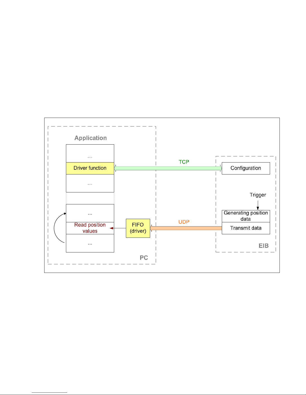
7.3 "Soft Real-Time" Operating Mode
The position data is transported with UDP packets from the EIB 74x to the PC. This occurs parallel to the TCP
communication via the standard Ethernet interface. The position data is generated when the EIB 74x receives a trigger
signal. With each trigger event, a data packet is sent to the PC automatically. Here, the packets can be read from a FIFO.
For operation in Soft Real-Time mode, the EIB 74x must be configured following the steps listed below.
• Initialization of the EIB 74x
• Initialization and configuration of the axes
• Configuration of the data packet
• Configuration of the trigger logic
• Selection of the operating mode (Soft Real-Time)
• Activation of the trigger source
The diagram below illustrates the communication process schematically. The customer software application has to configure
the EIB 74x. The data is then transmitted to the FIFO independently. From here, the application can read out the data within
a program loop.
Parallel to the position poll, the status of the EIB 74x can be requested or error messages cleared.
If the Ethernet connection is terminated in Soft Real-Time mode, e.g. by unplugging the Ethernet cable, the EIB 74x
deactivates the trigger source and transmits no further UDP packets. Once the connection has been restored, the EIB 74x
must be reconfigured for the operating mode.
When the application is closed, the above-mentioned initialization steps must be taken in the reverse order. The trigger
source must be deactivated first. The operating mode can then be changed or the connection to the EIB 74x closed.
Processing trigger events:
• External trigger inputs are supported
• Internal trigger sources are supported
• Software triggers are supported
For correct interpretation of the data, the composition of the data packet must be considered during data evaluation.
Page 26
26
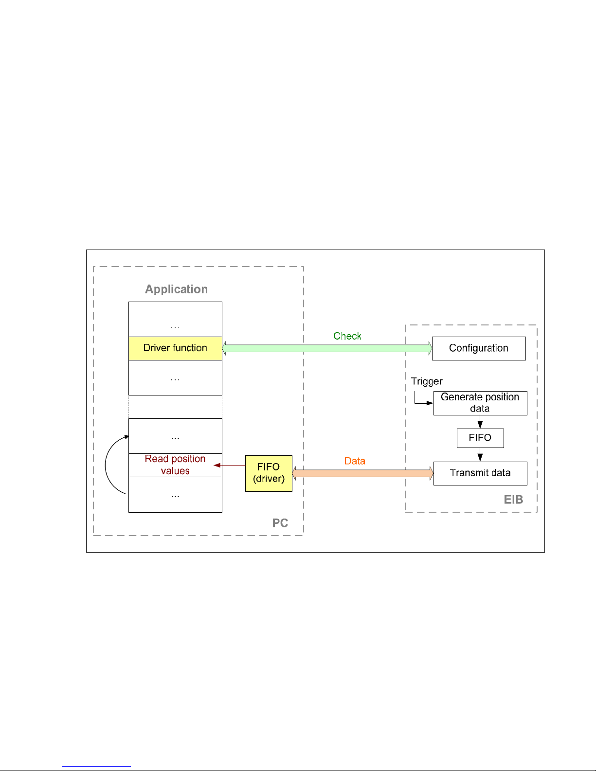
7.4 "Streaming" Operating Mode
The position data are buffered by the EIB 74x and transported to the PC. This occurs parallel to the TCP communication via
the standard Ethernet interface. The position data is generated when the EIB 74x receives a trigger signal. A data packet is
generated with each trigger event. Depending on the trigger rate and data volume, multiple data packets are consolidated
and transmitted to the PC. Here, the packets can be read from a FIFO.
For operation in Streaming mode, the EIB 74x must be configured following the steps listed below.
• Initialization of the EIB 74x
• Initialization and configuration of the axes
• Configuration of the data packet
• Configuration of the trigger logic
• Selection of the operating mode (Streaming)
• Activation of the trigger source
The diagram below illustrates the communication process schematically. The customer software application has to configure
the EIB 74x. The data is then transmitted to the FIFO independently. From here, the application can read out the data within
a program loop.
Parallel to the position poll, the status of the EIB 74x can be requested or error messages cleared. In particular, the status of
the FIFO in the EIB 74x can be interrogated in order to detect overflow early.
As soon as the position values from the FIFO are read on the PC, this is confirmed to the EIB. If further data are available in
the EIB 74x, they are transmitted.
When the application is closed, the above-mentioned initialization steps must be taken in the reverse order. The trigger
source must be deactivated first. The operating mode can then be changed or the connection to the EIB 74x closed.
Processing trigger events:
• External trigger inputs are supported
• Internal trigger sources are supported
• Software triggers are supported
For correct interpretation of the data, the composition of the data packet must be considered during data evaluation.
Page 27

27
7.5 "Recording" Operating Mode
The position data is saved in the memory of the EIB 74x. A data packet is generated and saved with each trigger event. After
the recording phase ends, the data can be transmitted.
The Recording operating mode supports two further modes. In Single Shot mode, data recording is automatically ended as
soon as the memory is full. In the Rolling mode the data is saved in a ring buffer. When the memory is full, the oldest entry
is overwritten. After the Recording mode is ended, the last n samples can be read from the memory.
The recording depth depends on the size of the data packet and can be read out (see Part 2, 7.42).
For operation in Recording mode, the EIB 74x must be configured following the steps listed below.
• Initialization of the EIB 74x
• Initialization and configuration of the axes
• Configuration of the data packet
• Configuration of the trigger logic
• Selection of the operating mode (Recording)
• Activation of the trigger source
After the recording phase is concluded, the following steps have to be taken:
• Deactivation of the trigger source
• Selection of the operating mode (Polling)
• Starting data transmission
The diagram below illustrates the communication process schematically. The customer software application has to configure
the EIB 74x. In the first phase (recording) the data is saved in the EIB 74x. In the second phase (data transmission) the data
is transmitted to the host and saved in a FIFO. From here, the application can read out the data within a program loop.
During the recording, the status of the EIB 74x can be requested or error messages cleared. In particular, the status of the
memory in the EIB 74x can be interrogated.
Processing trigger events:
• External trigger inputs are supported
• Internal trigger sources are supported
• Software triggers are supported
For correct interpretation of the data, the composition of the data packet must be considered during data evaluation.
Page 28

28
8 Firmware Update
The EIB 74x firmware can be updated by the user with a TFTP client. However, only special update files from HEIDENHAIN
may be installed on the EIB 74x.
The example below is based on a firmware update from a computer with "Windows" as its operating system.
The EIB 74x must be connected to the computer via Ethernet. In this example, the file name for the update is
"update_633281-10.flash". This file is saved under "C:\temp\EIB".
• Run the Windows command line
• Save the update file under "C:\temp\EIB\update_633281-10.flash"
• Start the TFTP file transfer:
> tftp –i 192.168.1.2 put C:\temp\EIB\update_633281-10.flash tmp\update.flash
Option -i: Activates the "binary file transfer"
IP address: "192.168.1.2" (default setting) or customer-specific setting
"Put" command: Transfer from the host to the EIB 74x
Source file: In this example "C:\temp\EIB\update_633281-10.flash"
Target file: Always "tmp\update.flash"
If the file has been transferred successfully, the TFTP client displays a corresponding message in the command line. The
status LED of the EIB 74x is switched off. After the internal data transmission to the flash memory, the status LED is
switched back on. This process can take up to 60 seconds. While the status LED is off, the power supply must not be
switched off and commands must not be sent to the EIB 74x via the Ethernet interface.
When the status LED is active again, the relevant software command is to be used to interrogate whether the update has
been completed successfully. The status of the update process can be polled until the EIB 74x is booted again.
The EIB 74x boots the new version of the firmware after the next reset.
In case of an error during the firmware update, the corresponding settings shown in the "Resetting the EIB 74x" table (see
"Commissioning Instructions") are booted.
9 Reset
See "Commissioning Instructions"
Page 29

29
Part 2: Driver Software
1 General Information
Functions are provided for accessing the EIB 74x from a software application. This group of functions is supplied as DLL for
Windows systems and as SO library for Linux. The following operating systems are supported:
− Windows 2000, Windows XP, Windows Vista, Windows 7
− Linux/Unix with kernel 2.6, (i386 systems)
In addition to the libraries, a header file that enables the functions to be integrated into C/C++ programs is also supplied. To
create a program, the library must be incorporated into the project.
".vi" files are provided for LabView. They have the Windows DLL as their basis. The designation, functionality and
input/output parameters of the ".vi" files orient themselves on the respective function calls, which are documented below.
Particularly for complex data types it might be possible that the ".vi" file needs an adaptation specific to LabView, along with
the DLL call. The corresponding adaptations are apparent when the ".vi" files are opened.
2 Installation Instructions
The stated directories and files refer to the driver CD for the EIB 74x.
2.1 Windows
For an application to load the DLL, file "eib7.dll" must be copied from the "EIB_74x\windows\bin" directory to the Windows
system directory (e.g. "C:\Windows\system32"). For 64-bit operating systems, the file "eib7_64.dll" must be copied from
"EIB_74x\windows\bin64" to the Windows system directory (e.g. "C:\Windows\system32") and renamed "eib7.dll". To ensure
compatibility with 32-bit applications, the file "eib7.dll" should be copied to the system directory "SysWOW64" in the
Windows folder (e.g. "C:\Windows"). Alternatively, the path for the DLL can be defined in the system. The DLL interface is
defined via the two files "eib7.lib" in "EIB_74x\windows\lib" and "eib7.h" in "EIB_74x\windows\include". These must be
incorporated into the software project in the development environment (for C/C++ environments). File "eib7.lib" must be
copied into the library directory of the development environment or its path entered.
2.2 Linux
For an application to load the SO library, for 32-bit operating systems the file "libeib7.so" on the CD must be copied from the
"EIB_74x/linux/lib" directory to the "usr/local/lib" directory. For 64-bit operating systems the file "libeib7_64.so" in the directory
"EIB_74x/linux/lib64" must be used and renamed "libeib7.so". The library interface is defined via file "eib7.h" in
"EIB_74x/linux/include". This must be copied to "usr/local/include" and must be incorporated into the software project in the
development environment. The stated directories are based on the "Filesystem Hierarchy Standard" for Linux operating
systems. The "libeib7.so" library was compiled for i386 systems under kernel 2.6.
3 Overview
3.1 Establishing Communication
To communicate with the EIB 74x, a connection must first be established using the EIB7Open() function. It is sometimes
necessary to determine the IP address beforehand using EIB7GetHostIP(). The EIB 74x can then be configured using the
device functions.
Access to the axes requires handles, which are generated by the EIB7GetAxis() function. This is also the case for the IO
ports, whose handles are generated by the EIB7GetIO() function. The handles can be used for configuration and for polling
the status.
At the end of communication, the connection must be closed using the EIB7Close() function.
3.2 Configuration of Data Packets
The data packet for the Soft Real-Time, Streaming and Recording operating modes must be configured before the modes are
activated.
The configuration data are saved in an array of the EIB7_DataPacketSection type. One element of the array must be
configured for each region. This can be done using the EIB7AddDataPacketSection() function (see 7.8). Then this
configuration can be loaded into the EIB 74x using the EIB7ConfigDataPacket() function (see 7.9).
Page 30

30
3.3 Polling Mode
The axis functions can be used to access the encoders. First, the axis must be configured via EIB7InitAxis(). The position
values can then be read out or error messages acknowledged.
It is not necessary to select a trigger source. The triggering occurs implicitly when the EIB7GetPosition() function is called.
3.4 Soft Real-Time Mode
First the axes have to be initialized with EIB7InitAxis() and the data packet as well as the trigger logic must be configured.
Then the Soft Real-Time mode can be activated. In Soft Real-Time mode, only the error messages from the status word for
the position values can be reset.
After you have switched to Soft Real-Time mode, the trigger source can be activated. The customer software application on
the host must continuously read the position data from the receive buffer to prevent an overflow. This can be done using the
EIB7ReadFIFOData() or EIB7ReadFIFODataRaw() functions (see 7.44, 7.47). Each of these functions reads one or several
entries from the FIFO. Each entry contains a data packet of the EIB 74x. The size of an entry can be determined in advance
using the EIB7SizeOfFIFOEntry() and EIB7SizeOfFIFOEntryRaw() functions (see 7.45, 7.48). The individual components of a
FIFO entry can be accessed using the EIB7GetDataFieldPtr() or EIB7GetDataFieldPtrRaw() function.
It is also possible to use the callback mechanism to register a function that is called as soon as new data is available in the
FIFO (see 7.54).
3.5 Streaming Mode
First the axes have to be initialized with EIB7InitAxis() and the data packet as well as the trigger logic must be configured.
Then the Streaming mode can be activated. In the Streaming mode, only the error messages from the status word for the
position values can be reset, and the status of the buffer can be read out (see 7.43).
After you have switched to the Streaming mode, the trigger source can be activated. The customer software application on the
host must continuously read the position data from the receive buffer to prevent an overflow. This can be done using the
EIB7ReadFIFOData() or EIB7ReadFIFODataRaw() functions (see 7.44, 7.47). Each of these functions reads one or several
entries from the FIFO. Each entry contains a data packet of the EIB 74x. The size of an entry can be determined in advance
using the EIB7SizeOfFIFOEntry() and EIB7SizeOfFIFOEntryRaw() functions (see 7.45, 7.48). The individual components of a
FIFO entry can be accessed using the EIB7GetDataFieldPtr() or EIB7GetDataFieldPtrRaw() function.
It is also possible to use the callback mechanism to register a function that is called as soon as new data is available in the
FIFO (see 7.54).
3.6 Recording Mode
First the axes have to be initialized with EIB7InitAxis() and the data packet as well as the trigger logic must be configured.
Once the Recording mode is active, the data is saved in the EIB 74x with each trigger event. The trigger source can be
selected in the Recording mode. The status of the buffer memory is readable (see 7.41).
Once the recording is finished, the data can be transmitted to the host. This is done in Polling mode. The transmission is
started with the EIB7TransferRecordingData() function. The customer's software application on the host can read out the
position data from the receiving buffer using the EIB7ReadFIFOData() or EIB7ReadFIFODataRaw() function (see 7.44, 7.47).
Each of these functions reads one or several entries from the FIFO. Each entry contains a data packet of the EIB 74x. The
size of an entry can be determined in advance using the EIB7SizeOfFIFOEntry() and EIB7SizeOfFIFOEntryRaw() functions
(see 7.45, 7.48). The individual components of a FIFO entry can be accessed using the EIB7GetDataFieldPtr() or
EIB7GetDataFieldPtrRaw() function.
Page 31

31
4 Data Types
4.1 Simple Data Types
EIB7_HANDLE Handle for an EIB 74x
EIB7_AXIS Handle for an axis on the EIB 74x
EIB7_IO Handle for an input or output port on the EIB 74x
EIB7_ERR Error message
ENCODER_POSITION Position value (64-bit integer)
4.2 EnDat Additional Datum
struct ENDAT_ADDINFO
Component Description
Status Status word for the additional datum
info Data of the additional datum
4.3 Information for TCP Connection
struct EIB7_CONN_INFO
Component Description
id Identification number for the connection
local_ip Local IP address for this connection
local_port Local port number for this connection
remote_ip IP address of the EIB 74x for this connection
remote_port Port number of the EIB 74x for this connection
4.4 Configuration for Data Packet
struct EIB7_DataPacketSection
Component Description
region Global information, or axis of the EIB 74x
items Data elements within the region
5 Parameters and Return Codes
All functions supply a return code of the type EIB7_ERR. This labels a function call as successful or reports an error that
occurred during execution.
Input values for the functions are transferred as variables (transfer by value). For return codes, a pointer to a variable is
transferred; this variable contains the result after the function has been successfully executed (transfer by reference).
Page 32

32
6 Auxiliary Functions
6.1 Determining the IP Address
The host name of the EIB 74x or the IP address (as C string) is converted to an IP address in "Host Byte Order." The name
must be transferred as a C string. Examples are "192.168.1.2" or "EIB74x-SN1234567".
Function
EIB7_ERR EIB7GetHostIP ( const char* hostname,
unsigned long* ip
)
Parameters
hostname Pointer to a C string containing the IP address or the host name of the EIB 74x.
ip [return code] Pointer to a variable to which the IP address of the EIB 74x is saved
Return code
The return code delivers a status for the function call. Possible values are listed below.
EIB7_NoError Function call successful
EIB7_HostNotFound IP address was unable to be determined
6.2 Changing the Position Data Format
The data format of a position value is converted from a 64-bit integer format to double format. The function can be used only
for incremental encoders. The converted value has the unit "1 signal period." The period counter value corresponds to the
part of the result before the decimal point; the decimal places are formed from the interpolation value.
Function
EIB7_ERR EIB7IncrPosToDouble ( ENCODER_POSITION src,
double* dest
)
Parameters
src Position value of an incremental encoder
ip [return code] Pointer to a variable to which the converted position is saved
Return code
The return code delivers a status for the function call. Possible values are listed below.
EIB7_NoError Function call successful
EIB7_ParamInvalid Transferred position value is invalid
Page 33

33
7 Device Functions
The device functions always refer to the entire EIB 74x. No distinction between the axes is possible. With some functions,
parameters of all axes are influenced.
All device functions are able to deliver the following error messages as a return code. They can also return further values
individually. These are listed separately for each function.
Standard return codes
EIB7_NoError Function call successful
EIB7_InvalidHandle The handle to the EIB 74x is invalid
EIB7_FuncNotSupp Function is not supported by the EIB 74x
EIB7_InvalidResponse Error during data transmission
EIB7_AccNotAllowed Function cannot be performed, as the EIB 74x does not permit access
EIB7_ConnReset Connection terminated by the EIB 74x
EIB7_ConnTimeout Timeout during data transmission to the EIB 74x
EIB7_ReceiveError Error while receiving the data
EIB7_SendError Error while sending the data
EIB7_OutOfMemory The system is unable to allocate sufficient memory
7.1 Opening a Connection to the EIB 74x
A TCP connection is established with the EIB 74x. This does not result in any changes in the settings in the EIB 74x. If the
connection cannot be established, an error message is returned. The driver must be compatible with the EIB 74x firmware to
function correctly. This is verified once the connection is established. If necessary, the EIB 74x firmware version can be read
using this function. To do this, the "ident" parameter must be used to transmit the address of a memory range to which the
version number is written as a C string.
Function
EIB7_ERR EIB7Open ( unsigned long ip,
EIB7_HANDLE* eib,
long timeout,
char* ident,
unsigned long len
)
Parameters
ip IP address in "Host Byte Order"
eib [return code] Handle for the EIB 74x if the function was closed successfully
timeout Timeout for subsequent commands in milliseconds (not valid for EIB7Open())
ident [return code] Pointer to the target memory in which the firmware version of the EIB 74x is
saved as a C string. This memory must be at least 9 bytes large. If this parameter is a NULL
pointer, the firmware version of the EIB 74x is not read.
len Size of the target memory in bytes (0, where ident = NULL)
Return code
The return code delivers a status for the function call. In addition to the standard return codes, the following error messages
can occur.
EIB7_CantInitWinSock Socket layer of the operating system cannot be initialized (applies only for Windows)
EIB7_CantOpenSocket System resources for connection not available
EIB7_OutOfMemory Insufficient memory available
EIB7_IFVersionInv EIB 74x firmware is incompatible with the driver
EIB7_CantConnect Connection cannot be established (EIB 74x may have been switched off or is unavailable)
Page 34

34
7.2 Closing the Connection to the EIB 74x
The connection to the EIB 74x is closed. The EIB Handle must not be used again. Likewise, all handles to axes generated
from this EIB handle are invalid. If a special operating mode of the EIB 74x has been activated via this handle, Polling mode
will be activated when the connection is closed. All other settings in the EIB 74x are retained.
Function
EIB7_ERR EIB7Close ( EIB7_HANDLE eib
)
Parameter
eib EIB handle
Return code
The return code delivers a status for the function call. All potential values are listed for the standard return codes.
7.3 Polling the Connection Status
The status of the connection to the EIB 74x is polled. This makes it possible to determine whether a connection has already
been closed or a communication error has occurred. This function does not send data to the EIB 74x. The status refers to the
previous commands.
Function
EIB7_ERR EIB7GetConnectionStatus ( EIB7_HANDLE eib,
EIB7_CONN_STATUS* status
)
Parameters
eib EIB handle
status [return code] Pointer to the target variable for the status
Status Description
EIB7_CS_Connected Connection to the EIB 74x established
EIB7_CS_Closed No connection to the EIB 74x
EIB7_CS_Timeout Time exceeded during data transmission
EIB7_CS_ConnectionReset The connection has been closed by the EIB 74x
EIB7_CS_TransmissionError Transmission error occurred
Return code
The return code delivers a status for the function call. All potential values are listed for the standard return codes.
7.4 Setting Up Timeout
The timeout for the TCP connection to the EIB 74x is reset. This value applies for all subsequent function calls. The timeout
must be at least 100 ms. Lower values are automatically increased to 100.
Function
EIB7_ERR EIB7SetTimeout ( EIB7_HANDLE eib,
long timeout
)
Parameters
eib EIB handle
timeout Timeout in milliseconds (>= 100)
Return code
The return code delivers a status for the function call. In addition to the standard return codes, the following error messages
can occur.
EIB7_IllegalParameter The timeout cannot be set
Page 35

35
7.5 Reading Out the Number of Axes
The number of axes with D-sub input in the EIB 74x is read out.
Function
EIB7_ERR EIB7GetNumOfAxes ( EIB7_HANDLE eib,
unsigned long* dsub,
unsigned long* res1,
unsigned long* res2,
unsigned long* res3
)
Parameters
eib EIB handle
dsub
[return code]
Pointer to the target variable for the number of axes with D-sub input
res1
[return code]
Reserved
res2
[return code]
Reserved
res3
[return code]
Reserved
Return code
The return code delivers a status for the function call. All potential values are listed for the standard return codes.
7.6 Requesting Handle for Axis
The handles for access to the axes of the EIB 74x are generated. They are saved in an array whose size must also be
transferred as a parameter. The number of valid handles is delivered as a return code. For each axis of the EIB 74x, the
function delivers one handle, the maximum being the number accommodated in the array ("size" parameter). The handles are
stored in the array in ascending order, starting with axis 1.
Function
EIB7_ERR EIB7GetAxis ( EIB7_HANDLE eib,
EIB7_AXIS* set,
unsigned long size,
unsigned long* len
)
Parameters
eib EIB handle
set [return code] Pointer to the first element of the handle array
size Maximum number of entries in the array
len [return code] Number of valid entries in the array
Return code
The return code delivers a status for the function call. All potential values are listed for the standard return codes.
7.7 Requesting IO Port Handle
Handles are generated for access to the IO ports of the EIB 74x. The handles for the inputs and the outputs are each saved
in an array whose size must also be transferred as a parameter. The number of valid handles in the array is generated in "ilen"
or "olen". For each IO port of the EIB 74x, the function delivers one handle, the maximum being the number accommodated
in the array ("isize", "osize" parameters).
Function
EIB7_ERR EIB7GetIO ( EIB7_HANDLE eib,
EIB7_IO* iset,
unsigned long isize,
unsigned long* ilen,
EIB7_IO* oset,
unsigned long osize,
unsigned long* olen
)
Parameters
eib EIB handle
iset [return code] Pointer to the first element of the array with the input handles
isize Maximum number of entries in the "iset" array
ilen [return code] Number of valid entries in the "iset" array
oset [return code] Pointer to the first element of the array with the output handles
osize Maximum number of entries in the "oset" array
olen [return code] Number of valid entries in the "oset" array
Return code
The return code delivers a status for the function call. All potential values are listed for the standard return codes.
Page 36

36
7.8 Creating a Data Packet
You can use this function to write the configuration for the data packet. One element from the array per function call is
initialized for the configuration data. The index indicates the element, whereby the first element has the index 0. Each
element consists of a region and the data elements. The region specifies the axis or the global information. Different data
elements can be added for each region. All data elements for a region must be OR gated and transmitted as the "items"
parameter. The data elements are specified as EIB7_DataPacketItem.
Function
EIB7_ERR EIB7AddDataPacketSection ( EIB_DataPacketSection* packet,
unsigned long index,
EIB7_DataRegion region,
unsigned long items
)
Parameters
packet Pointer to the array for the configuration data
index Index of the array element
region Region of the data packet
region Description
EIB7_DR_Global Global information
EIB7_DR_Encoder1 Data for axis 1
EIB7_DR_Encoder2 Data for axis 2
EIB7_DR_Encoder3 Data for axis 3
EIB7_DR_Encoder4 Data for axis 4
EIB7_DR_AUX Data for auxiliary axis
items Data elements within the region (OR gate of more than one element possible)
items Description
EIB7_PDF_TriggerCounter Trigger counter (only in EIB7_DR_Global)
EIB7_PDF_StatusWord Status word for position
EIB7_PDF_PositionData Position value
EIB7_PDF_Timestamp Timestamp for position
EIB7_PDF_Analog ADC values for signals A and B
EIB7_PDF_ReferencePos Reference position 1 and reference position 2
EIB7_PDF_DistCodedRef Coded reference value
EIB7_PDF_EnDat_AI1 EnDat 2.2 additional datum 1
EIB7_PDF_EnDat_AI2 EnDat 2.2 additional datum 2
Return code
The return code delivers a status for the function call. In addition to the standard return codes, the following error messages
can occur.
EIB7_ParamInvalid Parameter invalid
7.9 Configuring a Data Packet
The data packet for the Soft Real-Time, Streaming and Recording operating modes can be configured. The configuration is
possible only in the Polling mode. The configuration is effective as soon as another operating mode is activated (except
Polling).
Function
EIB7_ERR EIB7ConfigDataPacket ( EIB7_HANDLE eib,
EIB_DataPacketSection* packet,
unsigned long size
)
Parameters
eib EIB handle
packet Pointer to an array with the configuration data for the data packet
size Maximum number of entries in the "packet" array
Return code
The return code delivers a status for the function call. In addition to the standard return codes, the following error messages
can occur.
EIB7_ParamInvalid Parameter invalid
EIB7_PacketTooLong The configuration data describe an excessively long data packet
EIB7_InvalidPacket The configuration data describe an invalid data packet
Page 37

37
7.10 Selecting the Operating Mode
The operating mode for the EIB 74x can be set. The Polling and Soft Real-Time, Streaming and Recording modes are
supported. In the Recording operating mode you can choose between "single shot" and "rolling" operation.
Function
EIB7_ERR EIB7SelectMode ( EIB7_HANDLE eib,
EIB7_OPERATING_MODE mode
)
Parameters
eib EIB handle
mode Operating mode
mode Operating mode
EIB7_OM_Polling Polling mode
EIB7_OM_SoftRealtime Soft Real-Time mode
EIB7_OM_Streaming Streaming mode
EIB7_OM_RecordingSingle Recording mode, single shot
EIB7_OM_RecordingRoll Recording mode, rolling
Return code
The return code delivers a status for the function call. In addition to the standard return codes, the following error messages
can occur.
EIB7_CantOpenSocket Internal error (socket error)
EIB7_CantStartThread Internal error (thread error)
EIB7_InvalidOpMode The selected operating mode is not supported.
EIB7_OpModeActive The selected operating mode is already active
EIB7_OpModeBlocked The selected operating mode cannot be activated.
EIB7_InvalidIPAddr Internal error (IP address error)
7.11 Saving Network Parameters
The parameters for the Ethernet interface of the EIB 74x can be set. This means the EIB 74x can be adapted to the network.
The settings do not take effect until after the next boot process. If the DHCP client is active, the EIB 74x tries to obtain an IP
address from the DHCP server. If the server fails to respond within the set timeout, the configured IP address will be used.
Function
EIB7_ERR EIB7SetNetwork ( EIB7_HANDLE eib,
unsigned long ip,
unsigned long netmask,
unsigned long gateway,
EIB7_MODE dhcp,
unsigned long timeout
)
Parameters
eib EIB handle
ip IP address of the EIB 74x in "Host Byte Order"
netmask Network mask for the network in "Host Byte Order"
gateway IP address of the standard gateway in "Host Byte Order"
dhcp Flag for the DHCP client in the EIB 74x
dhcp Description
EIB7_MD_Disable Deactivate DHCP client
EIB7_MD_Enable Activate DHCP client
timeout Timeout for the DHCP client in seconds
Return code
The return code delivers a status for the function call. In addition to the standard return codes, the following error messages
can occur.
EIB7_CantSaveCustNW Network settings cannot be saved
EIB7_CantSaveDHCP DHCP timeout cannot be saved
EIB7_DHCPTimeoutInv DHCP timeout invalid
EIB7_ParamInvalid Parameters are not a valid network configuration
Page 38

38
7.12 Reading out the Network Parameters
The parameters for the Ethernet interface can be read. The user-defined settings are always displayed, even if standard
settings are used for booting.
Function
EIB7_ERR EIB7GetNetwork ( EIB7_HANDLE eib,
unsigned long* ip,
unsigned long* netmask,
unsigned long* gateway,
EIB7_MODE* dhcp
)
Parameters
eib EIB handle
ip [return code] Pointer to the variable for the IP address in "Host Byte Order"
netmask [return code] Pointer to the variable for the network mask in "Host Byte Order"
gateway [return code] Pointer to the variable for the IP address of the standard gateway in "Host Byte
Order"
dhcp [return code] Pointer to the variable for the flag for the DHCP client
dhcp Description
EIB7_MD_Disable DHCP client inactive
EIB7_MD_Enable DHCP client active
Return code
The return code delivers a status for the function call. In addition to the standard return codes, the following error messages
can occur.
EIB7_NoCustNetwork No customized settings present
7.13 Saving the Host Name
The host name of the EIB 74x is saved. The name must be transmitted as a C string, which can be a maximum of 32
characters long including the null byte. If it is any longer, the rest will be cut off. If a string with a length of zero or a NULL
pointer is transferred, the EIB 74x sets the host name to the factory default setting.
Function
EIB7_ERR EIB7SetHostname ( EIB7_HANDLE eib,
const char* hostname
)
Parameters
eib EIB handle
hostname Pointer to the new host name
Return code
The return code delivers a status for the function call. In addition to the standard return codes, the following error messages
can occur.
EIB7_HostnameTooLong Host name is too long
EIB7_HostnameInvalid Host name is invalid
EIB7_CantSaveHostn Host name cannot be saved
EIB7_CantRestDefHn Standard host name cannot be loaded
Page 39

39
7.14 Reading out the Host Name
The host name of the EIB 74x is read and saved in the target memory as a C string. The string is up to 32 characters long
(incl. the null byte). If the target memory is not big enough to take the entire string, only the first part is copied.
Function
EIB7_ERR EIB7GetHostname ( EIB7_HANDLE eib,
char* hostname,
unsigned long len
)
Parameters
eib EIB handle
hostname [return code] Pointer to the target memory for the host name
len Size of the target memory in bytes
Return code
The return code delivers a status for the function call. In addition to the standard return codes, the following error messages
can occur.
EIB7_CantRdHostname Host name cannot be read
7.15 Reading out the Serial Number
The serial number of the EIB 74x is displayed as a C string. The string is written to the target memory. If the target string
does not provide sufficient space for the serial number, an error will be generated. The serial number can be up to 24
characters long (incl. the null byte).
Function
EIB7_ERR EIB7GetSerialNumber ( EIB7_HANDLE eib,
char* serial,
unsigned long len
)
Parameters
eib EIB handle
serial [return code] Pointer to the target memory for the serial number
len Size of the target memory in bytes
Return code
The return code delivers a status for the function call. In addition to the standard return codes, the following error messages
can occur.
EIB7_CantRdSer Serial number cannot be read
EIB7_BufferTooSmall Target memory is too small
7.16 Reading out the Device ID
The device ID of the EIB 74x is generated as a C string. The string is written to the target memory. If the target string does
not provide sufficient space for the number, an error will be generated. The number can be up to 16 characters long (incl. the
null byte).
Function
EIB7_ERR EIB7GetIdentNumber ( EIB7_HANDLE eib,
char* ident,
unsigned long len
)
Parameters
eib EIB handle
ident [return code] Pointer to the target memory for the device number
len Size of the target memory in bytes
Return code
The return code delivers a status for the function call. In addition to the standard return codes, the following error messages
can occur.
EIB7_CantRdIdent Device number cannot be read
EIB7_BufferTooSmall Target memory is too small
Page 40

40
7.17 Reading out the MAC Address
The MAC address of the EIB 74x is displayed. The address is output in binary format. The target memory must be at least 6
bytes. The first six bytes are always used. The lowest-value byte of the MAC address is copied to the first byte of the target
memory. For example for "00:A0:CD:85:00:01".
Offset Memory contents
0 0x01
1 0x00
2 0x85
3 0xCD
4 0xA0
5 0x00
Function
EIB7_ERR EIB7GetMAC ( EIB7_HANDLE eib,
unsigned char* mac
)
Parameters
eib EIB handle
mac [return code] Pointer to the target memory for the MAC address
Return code
The return code delivers a status for the function call. All potential values are listed for the standard return codes.
7.18 Reading out the Firmware Version Number
The version number of the EIB 74x firmware is read. The "select" parameter determines the firmware from which the version
number is output as a C string. For the string, including the null byte, the target memory must be at least 9 bytes. If the
target memory is too small to take the entire string, only the first part is copied.
Function
EIB7_ERR EIB7GetVersion ( EIB7_HANDLE eib,
char* ident,
unsigned long len,
EIB7_FIRMWARE select
)
Parameters
eib EIB handle
ident [return code] Pointer to the target memory for the firmware version number
len Size of the target memory in bytes
select Selects the firmware whose version number is read
select Description
EIB7_FW_CurrentlyBooted Firmware currently loaded
EIB7_FW_Factory Firmware of factory default settings
EIB7_FW_User Firmware of the last update
Return code
The return code delivers a status for the function call. All potential values are listed for the standard return codes.
Page 41

41
7.19 Reading out the Boot Mode
The boot mode in which the EIB 74x was started during the last boot process is read out.
Function
EIB7_ERR EIB7GetBootMode ( EIB7_HANDLE eib,
EIB7_BOOT_MODE* mode
)
Parameters
eib EIB handle
status [return code] Pointer to the variable for boot mode
mode Description
EIB7_BM_User Firmware of the last update with user’s network settings
EIB7_BM_FactoryUser Firmware of factory default settings with user’s network
settings
EIB7_BM_FactoryDefault Firmware of factory default settings with standard network
settings
Return code
The return code delivers a status for the function call. All potential values are listed for the standard return codes.
7.20 Reading out the Update Status
The status can be read to verify whether an update was completed successfully. The function call automatically resets the
status to the default status (EIB7_US_NoUpdate) after the read operation. The status information is cleared during each boot
process.
Function
EIB7_ERR EIB7UpdateState ( EIB7_HANDLE eib,
EIB7_UPDATE_STATUS* status
)
Parameters
eib EIB handle
status [return code] Pointer to the variable for the update status
Status Description
EIB7_US_NoUpdate No update loaded
EIB7_US_UpdateFailed Update unable to be performed
EIB7_US_UpdateSuccessful Update performed successfully
EIB7_US_VersionIncompatible Firmware is incompatible with the EIB 74x hardware
Return code
The return code delivers a status for the function call. All potential values are listed for the standard return codes.
7.21 Reading the Number of Open Connections
The number of currently open connections to the EIB 74x is generated. This also includes semi-open connections that the
remote station has already closed but are still open on the EIB 74x.
Function
EIB7_ERR EIB7GetNumberOfOpenConnections ( EIB7_HANDLE eib,
unsigned long* cnt
)
Parameters
eib EIB handle
cnt [return code] Pointer to the variable for the number of open connections
Return code
The return code delivers a status for the function call. All potential values are listed for the standard return codes.
Page 42

42
7.22 Reading out the Connection Data
The connection data of all currently open connections to the EIB 74x can be read. For each connection, an array entry is
used. However, the maximum is the number specified by the "size" parameter. The number of valid elements in the array is
returned by the "cnt" parameter. The contents of the connection data are listed in the "Data types" section.
Function
EIB7_ERR EIB7ConnectionInfo ( EIB7_HANDLE eib,
EIB7_CONN_INFO* info,
unsigned long size,
unsigned long* cnt
)
Parameters
eib EIB handle
info [return code] Pointer to the first element in the array for the connection data
size Size of the "info" array
cnt [return code] Pointer to the variable for the number of valid elements in the array
Return code
The return code delivers a status for the function call. All potential values are listed for the standard return codes.
7.23 Terminating the Connection
An open connection to the EIB 74x can be terminated. It is not possible to close the connection used to call the function. The
primary use of this function is to close semi-open connections that have not been terminated properly due, for example, to
an error on the host. The ID can be taken from connection data EIB7_CONN_INFO (see "Read connection data").
Function
EIB7_ERR EIB7TerminateConnection ( EIB7_HANDLE eib,
unsigned long id
)
Parameters
eib EIB handle
id ID of the terminated connection
Return code
The return code delivers a status for the function call. In addition to the standard return codes, the following error messages
can occur.
EIB7_CantTermConn The connection cannot be terminated
EIB7_CantTermSelf The connection cannot terminate itself
EIB7_ParamInvalid The parameter is not a valid index for a connection
7.24 Reading the Time Unit Timestamp
The timestamp counter is supplied from a clock-pulse source. The timestamp ticks indicate how many clock pulses per
microsecond are generated from the clock-pulse source.
Function
EIB7_ERR EIB7GetTimestampTicks ( EIB7_HANDLE eib,
unsigned long* ticks
)
Parameters
eib EIB handle
ticks [return code] Pointer to the variable for the number of clock pulses per microsecond
Return code
The return code delivers a status for the function call. All potential values are listed for the standard return codes.
Page 43

43
7.25 Setting the Timestamp Period Duration
The period duration of the freely running timestamp counter can be set. To do this, the length of the timestamp period must
be indicated in timestamp ticks. This value must be a natural number greater than zero.
Function
EIB7_ERR EIB7SetTimestampPeriod ( EIB7_HANDLE eib,
unsigned long period
)
Parameters
eib EIB handle
period Ticks per timestamp period (> 0); also see “Note” in Chapter 4
Return code
The return code delivers a status for the function call. In addition to the standard return codes, the following error messages
can occur.
EIB7_ParamInvalid Timestamp period invalid
7.26 Resetting the Timestamp Counter
The timestamp counter is set to zero and continues counting from this value.
Function
EIB7_ERR EIB7ResetTimestamp ( EIB7_HANDLE eib
)
Parameter
eib EIB handle
Return code
The return code delivers a status for the function call. All potential values are listed for the standard return codes.
7.27 Reading the Timer-Trigger Time Unit
The timer trigger is supplied from a clock-pulse source. The timer-trigger ticks indicate how many clock pulses per
microsecond are generated by the clock-pulse source.
Function
EIB7_ERR EIB7GetTimerTriggerTicks ( EIB7_HANDLE eib,
unsigned long* ticks
)
Parameters
eib EIB handle
ticks [return code] Pointer to the variable for the number of clock pulses per microsecond
Return code
The return code delivers a status for the function call. All potential values are listed for the standard return codes.
7.28 Setting the Timer Trigger Period Duration
The period duration of the timer trigger can be set. To do this, the number of timer-trigger ticks making up a period must be
stated. This value must be a natural number greater than zero. If the timer trigger is activated, it will initiate a trigger event
after each period.
Function
EIB7_ERR EIB7SetTimerTriggerPeriod ( EIB7_HANDLE eib,
unsigned long period
)
Parameters
eib EIB handle
period Ticks per timer trigger period (> 0); also see “Note” in Chapter 4
Return code
The return code delivers a status for the function call. In addition to the standard return codes, the following error messages
can occur.
EIB7_ParamInvalid Trigger period invalid
Page 44

44
7.29 Reading the Time Unit for the Delay Time at the Trigger Inputs
The trigger input delay ticks indicate how many clock pulses per microsecond are generated by the clock-pulse source for
the delay time of the signals at the trigger input. The delay time of the trigger signals can be set to a multiple of the internal
clock-pulse period.
Function
EIB7_ERR EIB7GetTriggerDelayTicks ( EIB7_HANDLE eib,
unsigned long* ticks
)
Parameters
eib EIB handle
ticks
[return code]
Pointer to target variable for clock pulses per microsecond
Return code
The return code delivers a status for the function call. All potential values are listed for the standard return codes.
7.30 Clearing the Trigger Counter
The trigger counter is set to zero.
Function
EIB7_ERR EIB7ResetTriggerCounter ( EIB7_HANDLE eib
)
Parameter
eib EIB handle
Return code
The return code delivers a status for the function call. All potential values are listed for the standard return codes.
7.31 Software Trigger
The software trigger generates a trigger event and induces the EIB 74x to send data to the remote station. The "source"
parameter is used to select one of the software trigger channels. This function cannot be performed in Polling mode.
Function
EIB7_ERR EIB7SoftwareTrigger ( EIB7_HANDLE eib,
unsigned long source
)
Parameters
eib EIB handle
source Software trigger channel
source Description
EIB7_ST_SWtrigger1 Software trigger channel 1
EIB7_ST_SWtrigger2 Software trigger channel 2
EIB7_ST_SWtrigger3 Software trigger channel 3
EIB7_ST_SWtrigger4 Software trigger channel 4
Return code
The return code delivers a status for the function call. In addition to the standard return codes, the following error message
can occur.
EIB7_ParamInvalid Parameter invalid
Page 45

45
7.32 Selecting the Master Trigger Source
The master trigger signal can be selected from different sources. This function must be performed for the axes after
configuring the trigger matrix and is permitted only in the Polling mode.
Function
EIB7_ERR EIB7MasterTriggerSource ( EIB7_HANDLE eib,
EIB7_AxisTriggerSrc src
)
Parameters
eib EIB handle
src Trigger source
src Description
EIB7_AT_TrgInput1 Trigger input channel 1
EIB7_AT_TrgInput2 Trigger input channel 2
EIB7_AT_TrgInput3 Trigger input channel 3
EIB7_AT_TrgInput4 Trigger input channel 4
EIB7_AT_TrgSW1 Software trigger channel 1
EIB7_AT_TrgSW2 Software trigger channel 2
EIB7_AT_TrgSW3 Software trigger channel 3
EIB7_AT_TrgSW4 Software trigger channel 4
EIB7_AT_TrgRI Reference pulse of the corresponding axis
EIB7_AT_TrgRImaskedCH1 Gated reference pulse of axis 1 (A&B&RI)
EIB7_AT_TrgIC Interval counter
EIB7_AT_TrgPuls Pulse-counter trigger
EIB7_AT_TrgTimer Timer trigger
Return code
The return code delivers a status for the function call. In addition to the standard return codes, the following error messages
can occur.
EIB7_ParamInvalid Parameter invalid
Page 46

46
7.33 Activating Trigger Sources
The trigger sources of the EIB 74x can be activated/deactivated individually or collectively. The "src" parameter enables you to
select multiple trigger sources by gating the corresponding constants with an OR gate. The period duration for the timer
trigger must be configured before activation. If multiple trigger sources are activated by one function call, they are activated
simultaneously.
Function
EIB7_ERR EIB7GlobalTriggerEnable ( EIB7_HANDLE eib,
EIB7_MODE mode,
unsigned long src
)
Parameters
eib EIB handle
mode Activate or deactivate trigger sources
mode Description
EIB7_MD_Enable Activate trigger source
EIB7_MD_Disable Deactivate trigger source
src Trigger source
src Description
EIB7_TS_TrgInput1 Trigger input channel 1
EIB7_TS_TrgInput2 Trigger input channel 2
EIB7_TS_TrgInput3 Trigger input channel 3
EIB7_TS_TrgInput4 Trigger input channel 4
EIB7_TS_TrgRI1 Reference pulse of axis 1
EIB7_TS_TrgRI2 Reference pulse of axis 2
EIB7_TS_TrgRI3 Reference pulse of axis 3
EIB7_TS_TrgRI4 Reference pulse of axis 4
EIB7_TS_TrgRImaskedCH1 Gated reference pulse of axis 1 (A&B&RI)
EIB7_TS_TrgIC Interval counter
EIB7_TS_TrgPuls Pulse-counter trigger
EIB7_TS_TrgTimer Timer trigger
EIB7_TS_All All trigger sources
Return code
The return code delivers a status for the function call. In addition to the standard return codes, the following error messages
can occur.
EIB7_ParamInvalid Parameter invalid
Page 47

47
7.34 Configuring the Pulse Counter
A trigger signal and a start signal can be selected for the pulse counter. The start signal enables the pulse counter. The
counter will then be decremented with each pulse at the trigger signal until a value of zero is reached. Then all further trigger
pulses will be disabled. If the function is re-run before the counter has reached zero, the counter will be reset to the initial
value.
Function
EIB7_ERR EIB7ConfigPulsCounter ( EIB7_HANDLE eib,
EIB7_PulsCounterStart start,
EIB7_PulsCounterTrigger trigger,
unsigned long count
)
Parameters
eib EIB handle
start Start signal for pulse counter
start Description
EIB7_PS_TrgInput1 Trigger input channel 1
EIB7_PS_TrgInput2 Trigger input channel 2
EIB7_PS_TrgInput3 Trigger input channel 3
EIB7_PS_TrgInput4 Trigger input channel 4
EIB7_PS_TrgRI1 Reference pulse of axis 1
EIB7_PS_TrgRI2 Reference pulse of axis 2
EIB7_PS_TrgRI3 Reference pulse of axis 3
EIB7_PS_TrgRI4 Reference pulse of axis 4
EIB7_PS_TrgSW1 Software trigger channel 1
EIB7_PS_TrgSW2 Software trigger channel 2
EIB7_PS_TrgSW3 Software trigger channel 3
EIB7_PS_TrgSW4 Software trigger channel 4
EIB7_PS_TrgRImaskedCH1 Gated reference pulse of axis 1 (A&B&RI)
EIB7_PS_TrgIC Interval counter
trigger Trigger signal for pulse counter
trigger Description
EIB7_PT_TrgInput1 Trigger input channel 1
EIB7_PT_TrgInput2 Trigger input channel 2
EIB7_PT_TrgInput3 Trigger input channel 3
EIB7_PT_TrgInput4 Trigger input channel 4
EIB7_PT_TrgRI1 Reference pulse of axis 1
EIB7_PT_TrgRI2 Reference pulse of axis 2
EIB7_PT_TrgRI3 Reference pulse of axis 3
EIB7_PT_TrgRI4 Reference pulse of axis 4
EIB7_PT_TrgRImaskedCH1 Gated reference pulse of axis 1 (A&B&RI)
EIB7_PT_TrgIC Interval counter
EIB7_PT_TrgTimer Timer trigger
count Start value for pulse counter (0x00000 to 0xFFFFF)
Return code
The return code delivers a status for the function call. In addition to the standard return codes, the following error messages
can occur.
EIB7_ParamInvalid Parameter invalid
Page 48

48
7.35 Setting the Interpolation Factor for the Interval Counter
The interpolation factor for the interval counter is adjustable and determines the number of counting steps per signal period.
This setting has an effect on both the interval counter and the auxiliary axis. The number of counting steps per signal period
of the connected encoder is determined from the interpolation factor multiplied by the edge evaluation.
Function
EIB7_ERR EIB7SetIntervalCounterInterpolation ( EIB7_HANDLE eib,
EIB7_IntervalCounterIPF ipf,
EIB7_IntervalCounterEdge edge
)
Parameters
eib EIB handle
ipf Interpolation factor
ipf Description
EIB7_ICF_1x 1-fold interpolation
EIB7_ICF_2x 2-fold interpolation
EIB7_ICF_4x 4-fold interpolation
EIB7_ICF_5x 5-fold interpolation
EIB7_ICF_10x 10-fold interpolation
EIB7_ICF_20x 20-fold interpolation
EIB7_ICF_25x 25-fold interpolation
EIB7_ICF_50x 50-fold interpolation
EIB7_ICF_100x 100-fold interpolation
edge Edge evaluation
ipf Description
EIB7_ICE_1x 1-fold edge evaluation
EIB7_ICE_2x 2-fold edge evaluation
EIB7_ICE_4x 4-fold edge evaluation
Return code
The return code delivers a status for the function call. In addition to the standard return codes, the following error messages
can occur.
EIB7_ParamInvalid Parameter invalid
Page 49

49
7.36 Configuring the Interval Counter
This function is used to configure interval-counter triggering. The interval counter provides two modes. In the first mode, a
trigger pulse is generated only at a fixed position. This position is adjustable. The second mode permits triggering at fixed
intervals. The first trigger pulse is generated at the start position. Then a trigger pulse is generated at fixed intervals that can
be adjusted using the "interval" parameter. As an alternative, the current position can also be used as start position.
Function
EIB7_ERR EIB7SetIntervalCounterTrigger ( EIB7_HANDLE eib,
EIB7_IntervalCounterMode mode,
EIB7_IntervalCounterStart start,
unsigned long startpos,
unsigned long interval
)
Parameters
eib EIB handle
mode Trigger mode
mode Description
EIB7_ICM_Disable No triggering
EIB7_ICM_Single Triggering only at a fixed position
EIB7_ICM_Periodic Periodic triggering at fixed intervals
start Start of triggering
start Description
EIB7_ICS_Current Triggering starts at the current position
EIB7_ICS_StartPos Triggering starts at the start position
startpos Position value for the first trigger pulse
interval Interval between two trigger pulses in counting steps ( 6)
Return code
The return code delivers a status for the function call. In addition to the standard return codes, the following error messages
can occur.
EIB7_ParamInvalid Parameter invalid
7.37 Setting the Terminating Resistors
The terminating resistors for the incremental signals of the encoder inputs can be deactivated. This setting always applies for
all 1 V
PP
inputs on the EIB 74x. The resistors are activated after every boot process of the EIB 74x.
Function
EIB7_ERR EIB7EnableIncrementalTermination ( EIB7_HANDLE eib,
EIB7_MODE mode
)
Parameters
eib EIB handle
mode Activate or deactivate terminating resistors
mode Description
EIB7_MD_Disable Deactivate terminating resistors
EIB7_MD_Enable Activate terminating resistors
Return code
The return code delivers a status for the function call. In addition to the standard return codes, the following error messages
can occur.
EIB7_CantChIncInpTrm Mode cannot be changed
Page 50

50
7.38 Reset
The EIB 74x performs a reset and reboots. This function has the same effect as pressing the reset button. The standard boot
mode is used (firmware of the last update with user’s network settings). The connection to the EIB 74x is automatically
closed (as with EIB7Close).
Function
EIB7_ERR EIB7Reset ( EIB7_HANDLE eib
)
Parameter
eib EIB handle
Return code
The return code delivers a status for the function call. All potential values are listed for the standard return codes.
7.39 Identifying the EIB 74x
The LAN LED on the front panel of the EIB 74x can be set to flash mode. If several devices are arranged side by side, an
EIB 74x with a certain IP address is easily located. The LED flashes until the mode is terminated using the function.
Function
EIB7_ERR EIB7Identify ( EIB7_HANDLE eib,
EIB7_MODE mode
)
Parameters
eib EIB handle
mode Activate or deactivate LED flashing
mode Description
EIB7_MD_Disable Deactivate flash mode
EIB7_MD_Enable Activate flash mode
Return code
The return code delivers a status for the function call. In addition to the standard return codes, the following error messages
can occur.
EIB7_IllegalParameter LED status cannot be changed (parameter is invalid)
Page 51

51
7.40 Transferring the Recording Data
The transmission of data from the EIB 74x's internal recording buffer can be activated or deactivated. When the data
transmission is activated, it is possible to select only one range of the recorded data for transmission. The first byte to be
transmitted is given through the offset and the length specifies the number of bytes.
To transmit all the data, the parameter offset should be = 0 and length should be = 0xFFFFFFFF.
Function
EIB7_ERR EIB7TransferRecordingData ( EIB7_HANDLE eib,
EIB7_MODE mode,
unsigned long offset,
unsigned long length
)
Parameters
eib EIB handle
mode Activate or deactivate the data transmission
mode Description
EIB7_MD_Disable Stop data transmission
EIB7_MD_Enable Start data transmission
offset Offset for the first byte to be transmitted
length Number of bytes to be transmitted (0xFFFFFFFF = to the end of the recording)
Return code
The return code delivers a status for the function call. In addition to the standard return codes, the following error messages
can occur.
EIB7_CantOpenSocket Internal error (socket error)
EIB7_CantStartThread Internal error (thread error)
EIB7_OpModeBlocked The EIB 74x is not in the Polling mode.
EIB7_RecDataReadErr Data cannot be read from the EIB 74x.
EIB7_ParamInvalid Parameter invalid
7.41 Verifying the Recording Status
The status in the Recording mode can be read out. In addition, the current content in the buffer memory can be determined.
This is also possible during recording in the Recording mode. The progress of data transmission from out of the EIB 74x's
buffer to the host can also be read out.
Function
EIB7_ERR EIB7GetRecordingStatus ( EIB7_HANDLE eib,
unsigned long* length,
unsigned long* status,
unsigned long* progress
)
Parameters
eib EIB handle
length [return code] Pointer to the target variable for the number of data packets in the buffer
status [return code] Pointer to the target variable for the status
Status Description
0 Recording mode deactivated
1 Recording mode activated
2 Data is being transmitted
3 Waiting for connection setup for data transmission
progress [return code] Pointer to the target variable for the progress of data transmission
Progress in percent (0 to 100)
Return code
The return code delivers a status for the function call. All potential values are listed for the standard return codes.
Page 52

52
7.42 Reading the Recording Memory Size
The size of the memory for the recorded data in the EIB 74x can be read out. The size is provided as the number of data
packets that can be accommodated by the memory. This number depends on the size of a data packet. The data packet
must therefore be configured first.
Function
EIB7_ERR EIB7GetRecordingMemSize ( EIB7_HANDLE eib,
unsigned long* size
)
Parameters
eib EIB handle
size [return code] Pointer to the target variable for the size of the memory (as a number of data
packets)
Return code
The return code delivers a status for the function call. In addition to the standard return codes, the following error messages
can occur.
EIB7_InvalidPacket Current configuration for the data packet is invalid
7.43 Checking the Streaming Status
While the Streaming mode is active, the status of the buffer in the EIB 74x can be read out. In addition to the size of the
buffer in bytes, the quantity of currently saved data is indicated in bytes. Also, the maximum quantity of data in the buffer
since activation of the Streaming mode is indicated in bytes.
Function
EIB7_ERR EIB7GetStreamingStatus ( EIB7_HANDLE eib,
unsigned long* length,
unsigned long* max,
unsigned long* size
)
Parameters
eib EIB handle
length [return code] Pointer to the target variable for the number of bytes in the buffer
max [return code] Pointer to the target variable for the maximum number of bytes in the buffer
since the start of the Streaming mode
size [return code] Pointer to the target variable for the size of the buffer in bytes
Return code
The return code delivers a status for the function call. All potential values are listed for the standard return codes.
Page 53

53
7.44 Reading Data from the FIFO
Data packets are copied from the FIFO to the target memory (in raw data format). The "cnt" parameter indicates the number
of entries to be copied from the FIFO. If the FIFO contains fewer data records, the entire content of the FIFO is copied. The
number of entries actually copied is returned via the "entries" parameter. The function waits until at least one data record has
been copied from the FIFO, though no longer than expiration of the timeout. In this case, zero is returned to "entries". Entire
data packets are always copied from the FIFO. The target memory must be at least big enough to take the indicated number
of FIFO entries. The content of an entry in FIFO corresponds to the currently configured data packet without the appended
"fill bytes." All data words are saved in the "Little Endian" format.
Function
EIB7_ERR EIB7ReadFIFODataRaw ( EIB7_HANDLE eib,
void* data,
unsigned long cnt,
unsigned long* entries,
long timeout
)
Parameters
eib EIB handle
data [return code] Pointer to target memory
cnt Number of entries to be read (>= 0)
entries [return code] Number of entries to be copied
timeout Timeout in milliseconds
timeout Description
0 Function returns immediately if no data is
present
>0 Function waits for data for x milliseconds
-1 Function waits indefinitely
Return code
The return code delivers a status for the function call. In addition to the standard return codes, the following error messages
can occur.
EIB7_FIFOEmpty No data in the FIFO
EIB7_ElementSizeInv Internal error
EIB7_FIFOOverflow FIFO overflow since the function was last called (data was lost)
7.45 Reading the Size of a FIFO Element
The size of a FIFO element in raw data format is generated. This value corresponds to the size of a FIFO entry, which is read
using the EIB7ReadFIFODataRaw() function. A FIFO element contains a data packet whose size depends on the present
configuration. The size is given without "fill bytes."
Function
EIB7_ERR EIB7SizeOfFIFOEntryRaw ( EIB7_HANDLE eib,
unsigned long* size
)
Parameters
eib EIB handle
size [return code] Pointer to the variable for the size of a FIFO element in bytes
Return code
The return code delivers a status for the function call. All potential values are listed for the standard return codes.
Page 54

54
7.46 Access to the Contents of a FIFO Element
This function can be used to access individual fields of a FIFO element (in raw data). A FIFO entry can contain, for example,
the trigger counter, position data, the status word and additional data. The content of the data packet can vary depending on
its configuration. When the elements are accessed, this must be remembered in order to interpret the data correctly. This
function provides a pointer to the relevant field within the data structure and also the field size in bytes. A general selection is
made using the "region" parameter. This makes it possible to select the axis from which the field is obtained. The fine
selection can be made using the "type" parameter. This indicates which data field of an axis is to be accessed.
Function
EIB7_ERR EIB7GetDataFieldPtrRaw ( EIB7_HANDLE eib,
void* data,
EIB7_DataRegion region,
EIB7_PositionDataField type,
void** field,
unsigned long* size
)
Parameters
eib EIB handle
data Pointer to the data structure (FIFO element)
region Axis of the EIB 74x
region Description
EIB7_DR_Global Global data field for trigger counter
EIB7_DR_Encoder1 Data for axis 1
EIB7_DR_Encoder2 Data for axis 2
EIB7_DR_Encoder3 Data for axis 3
EIB7_DR_Encoder4 Data for axis 4
EIB7_DR_AUX Data for auxiliary axis
type Data element for an axis
type Description
EIB7_PDF_TriggerCounter Trigger counter (only in EIB7_DR_Global)
EIB7_PDF_StatusWord Status word for position
EIB7_PDF_PositionData Position value
EIB7_PDF_AUXPosition Position value for auxiliary axis
EIB7_PDF_Timestamp Timestamp for position
EIB7_PDF_Analog ADC value for signals A and B
EIB7_PDF_ReferencePos Reference position 1 and reference position 2
EIB7_PDF_DistCodedRef Coded reference value
EIB7_PDF_EnDat_AI1 EnDat 2.2 additional datum 1
EIB7_PDF_EnDat_AI2 EnDat 2.2 additional datum 2
field [return code] Pointer to the memory address of the element from the data structure
size [return code] Size of the element in bytes
Return code
The return code delivers a status for the function call. In addition to the standard return codes, the following error messages
can occur.
EIB7_FieldNotAvail The indicated field cannot be found
Page 55

55
7.47 Reading and Converting Data from the FIFO
Data packets are copied from the FIFO to the target memory and converted. The "cnt" parameter indicates the number of
entries to be copied from the FIFO. If the FIFO contains fewer data records, the entire content of the FIFO is copied. The
number of entries actually copied is returned via the "entries" parameter. The function waits until at least one data record has
been copied from the FIFO, though no longer than expiration of the timeout. In this case, zero is returned to "entries". Entire
data packets are always copied from the FIFO. The target memory must be at least big enough to take the indicated number
of FIFO entries. The content of an entry corresponds to the currently configured data packet without the appended "fill
bytes." All data words are saved in the standard format for 16-bit or 32-bit integers and the position values are converted to
the ENCODER_POSITION format.
Function
EIB7_ERR EIB7ReadFIFOData ( EIB7_HANDLE eib,
void* data,
unsigned long cnt,
unsigned long* entries,
long timeout
)
Parameters
eib EIB handle
data [return code] Pointer to target memory
cnt Number of entries to be read (>= 0)
entries [return code] Number of entries to be copied
timeout Timeout in milliseconds
timeout Description
0 Function returns immediately if no data is
present
>0 Function waits for data for x milliseconds
–1 Function waits indefinitely
Return code
The return code delivers a status for the function call. In addition to the standard return codes, the following error messages
can occur.
EIB7_FIFOEmpty No data in the FIFO
EIB7_ElementSizeInv Internal error
EIB7_FIFOOverflow FIFO overflow since the function was last called (data was lost)
7.48 Reading the Size of a FIFO Element Following Conversion
The size of a FIFO element is generated following conversion. This value corresponds to the size of a FIFO entry, which is
read using the EIB7ReadFIFOData() function. A FIFO element contains a data packet whose size depends on the present
configuration. The size is given without "fill bytes."
Function
EIB7_ERR EIB7SizeOfFIFOEntry ( EIB7_HANDLE eib,
unsigned long* size
)
Parameters
eib EIB handle
size [return code] Pointer to the variable for the size of a FIFO element in bytes
Return code
The return code delivers a status for the function call. All potential values are listed for the standard return codes.
Page 56

56
7.49 Access to the Contents of a FIFO Element with Converted Data
This function can be used to access individual fields of a FIFO element with converted position data (ENCODER_POSITION
format). A FIFO entry can contain, for example, the trigger counter, position data, the status word and additional data. The
content of the data packet can vary depending on its configuration. When the elements are accessed, this must be
remembered in order to interpret the data correctly. This function provides a pointer to the relevant field within the data
structure and also the field size in bytes. A general selection is made using the "region" parameter. This makes it possible to
select the axis from which the field is obtained. The fine selection can be made using the "type" parameter. This indicates
which data field of an axis is to be accessed.
Function
EIB7_ERR EIB7GetDataFieldPtr ( EIB7_HANDLE eib,
void* data,
EIB7_DataRegion region,
EIB7_PositionDataField type,
void** field,
unsigned long* size
)
Parameters
eib EIB handle
data Pointer to the data structure (FIFO element)
region Axis of the EIB 74x
region Description
EIB7_DR_Global Global data field for trigger counter
EIB7_DR_Encoder1 Data for axis 1
EIB7_DR_Encoder2 Data for axis 2
EIB7_DR_Encoder3 Data for axis 3
EIB7_DR_Encoder4 Data for axis 4
EIB7_DR_AUX Data for auxiliary axis
type Data element for an axis
type Description
EIB7_PDF_TriggerCounter Trigger counter (only in EIB7_DR_Global)
EIB7_PDF_StatusWord Status word for position
EIB7_PDF_PositionData Position value
EIB7_PDF_AUXPosition Position value for auxiliary axis
EIB7_PDF_Timestamp Timestamp for position
EIB7_PDF_Analog ADC value for signals A and B
EIB7_PDF_ReferencePos Reference position 1 and reference position 2
EIB7_PDF_DistCodedRef Coded reference value
EIB7_PDF_EnDat_AI1 EnDat 2.2 additional datum 1
EIB7_PDF_EnDat_AI2 EnDat 2.2 additional datum 2
field [return code] Pointer to the memory address of the element from the data structure
size [return code] Size of the element in bytes
Return code
The return code delivers a status for the function call. In addition to the standard return codes, the following error messages
can occur.
EIB7_FieldNotAvail The indicated field cannot be found
7.50 Reading the Number of Elements in the FIFO
The number of elements currently stored in the FIFO is generated.
Function
EIB7_ERR EIB7FIFOEntryCount ( EIB7_HANDLE eib,
unsigned long* cnt
)
Parameters
eib EIB handle
cnt [return code] Pointer to the variable for the number of FIFO elements
Return code
The return code delivers a status for the function call. All potential values are listed for the standard return codes.
Page 57

57
7.51 Clearing the FIFO
The contents of the FIFO are cleared. This command has no effect if Polling mode is active.
Function
EIB7_ERR EIB7ClearFIFO ( EIB7_HANDLE eib
)
Parameters
eib EIB handle
Return code
The return code delivers a status for the function call. All potential values are listed for the standard return codes.
7.52 Setting the FIFO Size
The size of the FIFO is reestablished. All data in the FIFO is cleared. The size can only be set in Polling mode. The FIFO must
be at least 2000 bytes large. If the value is smaller, the value of 2000 bytes is used internally.
Function
EIB7_ERR EIB7SetFIFOSize ( EIB7_HANDLE eib,
unsigned long size
)
Parameters
eib EIB handle
size FIFO size in bytes
Return code
The return code delivers a status for the function call. In addition to the standard return codes, the following error messages
can occur.
EIB7_SoftRTEn Soft Real-Time mode is activated
7.53 Reading the FIFO Size
The size of the FIFO in bytes is generated.
Function
EIB7_ERR EIB7GetFIFOSize ( EIB7_HANDLE eib,
unsigned long* size
)
Parameters
eib EIB handle
size [return code] Pointer to the variable for the FIFO size in bytes
Return code
The return code delivers a status for the function call. All potential values are listed for the standard return codes.
Page 58

58
7.54 Activating the Callback Mechanism
The callback mechanism is activated or deactivated and the function pointer saved where applicable. The callback function is
called if there are at least as many elements saved in the FIFO as there are in the "threshold" parameter. This function will
then not be called until new data has been written to the FIFO and then at least "threshold" elements have been saved in the
FIFO.
Function
EIB7_ERR EIB7SetDataCallback ( EIB7_HANDLE eib,
void* data,
EIB7_MODE activate,
unsigned long threshold,
EIB7OnDataAvailable handler
)
Parameters
eib EIB handle
data Pointer to user data, this pointer is transmitted as a parameter to the callback function
activate Activate or deactivate callback
Activate Description
EIB7_MD_Disable Deactivate the callback mechanism
EIB7_MD_Enable Activate the callback mechanism
threshold Number of elements in the FIFO from which the callback mechanism is triggered (> 0)
handler Pointer to the callback function (NULL is permitted if activate = 0)
Return code
The return code delivers a status for the function call. All potential values are listed for the standard return codes.
Callback function
The callback function is performed by the driver and runs in a separate thread. The user must attend to any necessary
synchronization with the main program. The "eib" parameter contains the handle to the EIB 74x that has triggered the
callback. "cnt" indicates the number of elements currently stored in the FIFO. The "data" parameter contains the pointer that
was indicated when registering the callback function.
Prototype
typedef void (*EIB7OnDataAvailable) ( EIB7_HANDLE eib,
unsigned long cnt,
void* data
)
Parameters
eib EIB handle
cnt Number of elements in the FIFO
data Pointer to user data
Page 59

59
7.55 Selecting the Trigger Source for the Auxiliary Axis
The trigger signal for the auxiliary axis can be selected from different sources. This setting is possible only in the Polling
mode.
Function
EIB7_ERR EIB7AuxAxisTriggerSource ( EIB7_HANDLE eib,
EIB7_AxisTriggerSrc src
)
Parameters
eib EIB handle
src Trigger source
src Description
EIB7_AT_TrgInput1 Trigger input channel 1
EIB7_AT_TrgInput2 Trigger input channel 2
EIB7_AT_TrgInput3 Trigger input channel 3
EIB7_AT_TrgInput4 Trigger input channel 4
EIB7_AT_TrgSW1 Software trigger channel 1
EIB7_AT_TrgSW2 Software trigger channel 2
EIB7_AT_TrgSW3 Software trigger channel 3
EIB7_AT_TrgSW4 Software trigger channel 4
EIB7_AT_TrgRI Reference pulse of the corresponding axis
EIB7_AT_TrgRImaskedCH1 Gated reference pulse of axis 1 (A&B&RI)
EIB7_AT_TrgIC Interval counter
EIB7_AT_TrgPuls Pulse-counter trigger
EIB7_AT_TrgTimer Timer trigger
Return code
The return code delivers a status for the function call. In addition to the standard return codes, the following error messages
can occur.
EIB7_ParamInvalid Parameter invalid
7.56 Reading the Position of the Auxiliary Axis
The current position value is read out. A status word informing about potential position errors is also transmitted. The
position can only be polled in Polling mode. The setting of the interpolation factor and the edge evaluation for the interval
counter determine the significance of an LSB (Lowest Significant Bit) in the position value with respect to the signal period of
the encoder.
Function
EIB7_ERR EIB7AuxGetPosition ( EIB7_HANDLE eib,
unsigned short* status,
ENCODER_POSITION* pos
)
Parameters
eib EIB handle
status
[return code]
Pointer to the target variable for the status word
pos
[return code]
Pointer to the target variable for the position
Return code
The return code delivers a status for the function call. In addition to the standard return codes, the following error messages
can occur.
EIB7_CantLatchPos Position cannot be determined
EIB7_EncPwrSuppErr Error in the encoder power supply
EIB7_NotInitialized Auxiliary axis is not configured
Page 60

60
7.57 Reading Out the Data of the Auxiliary Axis
The current position and certain additional parameters are determined and read out. The function may only be performed in
Polling mode. The status word indicates whether the position and the reference position are valid. The position value and the
timestamp are saved simultaneously. This requires the internal use of software trigger channel 1. The trigger source for the
auxiliary axis is configured accordingly, thereby overwriting the current setting.
Function
EIB7_ERR EIB7AuxGetEncoderData ( EIB7_HANDLE eib,
unsigned short* status,
ENCODER_POSITION* pos,
ENCODER_POSITION* ref,
unsigned long* timestamp,
unsigned short* counter
)
Parameters
eib EIB handle
status
[return code]
Pointer to the target variable for the status word
pos
[return code]
Pointer to the target variable for the position
ref
[return code]
Pointer to the target variable for the reference position
timestamp
[return code]
Pointer to the target variable for the timestamp value
counter
[return code]
Pointer to the target variable for the trigger counter
Return code
The return code delivers a status for the function call. In addition to the standard return codes, the following error messages
can occur.
EIB7_CantLatchPos Position cannot be determined
EIB7_EncPwrSuppErr Error in the encoder power supply
EIB7_NotInitialized Auxiliary axis is not configured
7.58 Clearing the Counter of the Auxiliary Axis
The position counter of the auxiliary axis is cleared.
Function
EIB7_ERR EIB7AuxClearCounter ( EIB7_HANDLE eib
)
Parameters
eib EIB handle
Return code
The return code delivers a status for the function call. All potential values are listed for the standard return codes.
7.59 Acknowledging the Signal Errors of the Auxiliary Axis
The error messages for the auxiliary axis are cleared. This applies to the error for the signal amplitude and the error for
exceeding the frequency.
Function
EIB7_ERR EIB7AuxClearSignalErrors ( EIB7_HANDLE eib
)
Parameters
eib EIB handle
Return code
The return code delivers a status for the function call. All potential values are listed for the standard return codes.
Page 61

61
7.60 Acknowledging the Trigger Errors of the Auxiliary Axis
The error messages for undetected trigger events for the auxiliary axis in the trigger logic are cleared.
Function
EIB7_ERR EIB7AuxClearLostTriggerError ( EIB7_HANDLE eib
)
Parameters
eib EIB handle
Return code
The return code delivers a status for the function call. All potential values are listed for the standard return codes.
7.61 Clearing the Status Bit for the Reference Mark of the Auxiliary Axis
The "Reference position saved" flag in the status word for the auxiliary axis is reset.
Function
EIB7_ERR EIB7AuxClearRefStatus ( EIB7_HANDLE eib
)
Parameters
eib EIB handle
Return code
The return code delivers a status for the function call. All potential values are listed for the standard return codes.
7.62 Checking the Status of the Reference Run for the Auxiliary Axis
The status of the reference run is output. It indicates whether the reference run is still active, or the reference positions have
already been saved.
Function
EIB7_ERR EIB7AuxGetRefActive ( EIB7_HANDLE eib,
EIB7_MODE* active
)
Parameters
eib EIB handle
active
[return code]
Pointer to the variable for the status of the reference run
active Description
EIB7_MD_Enable Reference run active
EIB7_MD_Disable Reference run not active
Return code
The return code delivers a status for the function call. All potential values are listed for the standard return codes.
7.63 Starting a Reference Run for the Auxiliary Axis
After this command has been called, the reference position is saved when the next reference pulse is traversed. The saved
value corresponds to the period counter status at the reference mark position. The status of a previously saved reference
position is set to invalid as soon as a reference run has been started.
Function
EIB7_ERR EIB7AuxStartRef ( EIB7_HANDLE eib
)
Parameters
eib EIB handle
Return code
The return code delivers a status for the function call. All potential values are listed for the standard return codes.
Page 62

62
7.64 Stopping a Reference Run for the Auxiliary Axis
The reference run (mode for automatically saving the reference position) is stopped. Reference positions that have already
been saved are not deleted.
Function
EIB7_ERR EIB7AuxStopRef ( EIB7_HANDLE eib
)
Parameters
eib EIB handle
Return code
The return code delivers a status for the function call. All potential values are listed for the standard return codes.
7.65 Configuring a Timestamp for the Auxiliary Axis
The timestamp can be activated or deactivated for the auxiliary axis. The global setting of the EIB 74x is used for the period
duration. The timestamp value is copied during a position poll for the auxiliary axis if this function was activated beforehand.
Function
EIB7_ERR EIB7AuxSetTimestamp ( EIB7_HANDLE eib,
EIB7_MODE mode
)
Parameters
eib EIB handle
mode Activate or deactivate timestamp
mode Description
EIB7_MD_Enable Activate timestamp
EIB7_MD_Disable Deactivate timestamp
Return code
The return code delivers a status for the function call. All potential values are listed for the standard return codes.
7.66 Setting the Trigger Edge for the Reference Pulse of the Auxiliary Axis
The time for reference-pulse triggering for the auxiliary axis can be set to the rising or falling edge or to both edges of the
reference-pulse signal. If both edges are used for the trigger event, it must be ensured that the maximum trigger rate is not
exceeded.
Function
EIB7_ERR EIB7AuxSetRITriggerEdge ( EIB7_HANDLE eib,
EIB7_RITriggerEdge edge
)
Parameters
eib EIB handle
edge Active trigger edge for the reference pulse
edge Description
EIB7_RI_Rising Rising edge of the reference pulse
EIB7_RI_Falling Falling edge of the reference pulse
EIB7_RI_Both Both edges of the reference pulse
Return code
The return code delivers a status for the function call. In addition to the standard return codes, the following error messages
can occur.
EIB7_ParamInvalid Parameter invalid
Page 63

63
8 Axis Functions
The axis functions always refer to just one axis on the EIB 74x. None of the other axes is affected.
All axis functions are able to deliver the following error messages as a return code. They can also return further values
individually. These are listed separately for each function.
Standard return codes
EIB7_NoError Function call successful
EIB7_InvalidHandle The handle to the axis of the EIB 74x is invalid
EIB7_FuncNotSupp Function is not supported by the EIB 74x
EIB7_InvalidResponse Error during data transmission
EIB7_AccNotAllowed Function cannot be performed, as the EIB 74x does not permit access
EIB7_ConnReset Connection terminated by the EIB 74x
EIB7_ConnTimeout Timeout during data transmission to the EIB 74x
EIB7_ReceiveError Error while receiving the data
EIB7_SendError Error while sending the data
EIB7_OutOfMemory The system is unable to allocate sufficient memory
8.1 Initializing the Axis
An axis of the EIB 74x is configured for the connected encoder. The axis number of the EIB 74x is determined via the axis
handle. The interface type of the encoder must be selected as a basic option. Certain parameters are required only for
incremental interfaces and others only for EnDat interfaces. For an EnDat 2.2 interface, the delay compensation can also be
activated using the "iface" parameter. To do this, the constants "EIB7_IT_EnDat22" and "EIB7_IT_EnDatDelayMeasurement"
must be gated with "Or".
The "EnDatclock," "recovery" and "calculation" parameters are used only for encoders with the EnDat interface. The EnDat
interface clock can be set. This must be done using pre-defined constants. Upon initialization of an axis for EnDat mode, an
EnDat reset command is sent to the connected encoder. In addition, using the "recovery" parameter, the "recovery time I"
can be set for EnDat 2.2 encoders (ordering designation EnDat02 or EnDat22). The "EnDat calculation time‘‘ has to be
adjusted in the "calculation" parameter for the encoder.
The "bandwidth" and "comp" parameters are effective only for incremental encoders. Two states (high and low) are available
for configuring the bandwidth. The online compensation function can be activated and deactivated. The values for
"linecounts" and "increment" are required only in conjunction with distance-coded reference marks.
Calling this function clears the following flags:
• Signal amplitude error
• Frequency exceeded
• Reference position 1 saved
• Reference position 2 saved
• Coded reference value valid for distance-coded reference marks
• Error while calculating the coded reference value for distance-coded reference marks
• CRC error
The settings for the terminating resistors of the incremental signals as well as the value of the period counter are not
influenced by the function.
Page 64

64
Function
EIB7_ERR EIB7InitAxis ( EIB7_AXIS axis,
unsigned long iface,
EIB7_EncoderType type,
EIB7_Refmarks refmarks,
unsigned long linecounts,
unsigned long increment,
EIB7_Homing homing,
EIB7_Limit limit,
EIB7_Compensation comp,
EIB7_Bandwidth bandwidth,
unsigned long EnDatclock,
EIB7_EnDatRecoveryTime recovery,
EIB7_EnDatCalcTime calculation,
)
Parameters
axis AXIS handle
iface Interface type of the encoder
Iface Description
EIB7_IT_Disabled Axis deactivated
EIB7_IT_Incremental Encoder with incremental signals (1 VPP)
EIB7_IT_Incremental_11u Encoder with incremental signals (11 µA)
EIB7_IT_EnDat21 Encoder with EnDat 2.1 interface
EIB7_IT_EnDat01 Encoder with EnDat 2.1 interface and
incremental signals (1 V
PP
)
EIB7_IT_EnDat22 Encoder with EnDat 2.2 interface
EIB7_IT_EnDatDelayMeasurement Delay compensation for EnDat 2.2
type Encoder type
type Description
EIB7_EC_Linear Linear encoder
EIB7_EC_Rotary Angle encoder / rotary encoder
refmarks Type of reference marks
Refmarks Description
EIB7_RM_None No reference mark
EIB7_RM_One One reference mark
(EIB 74x does not calculate a coded
reference value)
EIB7_RM_DistanceCoded Distance-coded reference marks
(EIB 74x calculates coded reference value
automatically)
linecounts Number of signal periods per revolution (only for rotary encoders)
increment Nominal distance in signal periods between two fixed reference marks (only for distance-
coded reference marks)
homing Activate or deactivate evaluation of the homing signal
homing Description
EIB7_HS_None Homing signal is not evaluated
EIB7_HS_Available Homing signal is evaluated
limit Activate or deactivate evaluation of the limit signal
limit Description
EIB7_LS_None Limit signal is not evaluated
EIB7_LS_Available Limit signal is evaluated
compensation Activate or deactivate online compensation
Compensation Description
EIB7_CS_None Signal compensation deactivated
EIB7_CS_CompActive Signal compensation activated
Page 65

65
bandwidth Input bandwidth for incremental signals (high/low)
Bandwidth Description
EIB7_BW_High High input bandwidth for 1 VPP signals
EIB7_BW_Low Low input bandwidth for 1 VPP signals
EnDatclock EnDat clock rate
EnDatclock Description
EIB7_CLK_Default Default EnDat 2.1 / EnDat 2.2 clock
EIB7_CLK_100KHz EnDat clock 100 kHz
EIB7_CLK_300KHz EnDat clock 300 kHz (default for EnDat 2.1)
EIB7_CLK_500KHz EnDat clock 500 kHz
EIB7_CLK_1MHz EnDat clock 1 MHz
EIB7_CLK_2MHz EnDat clock 2 MHz (default for EnDat 2.2)
EIB7_CLK_4MHz EnDat clock 4 MHz
EIB7_CLK_5MHz EnDat clock 5 MHz
EIB7_CLK_6_66MHz EnDat clock 6.66 MHz
recovery Recovery time I for EnDat 2.2
recovery Description
EIB7_RT_Long Long recovery time I according to the EnDat specification
EIB7_RT_Short Short recovery time I according to the EnDat
specification
calculation Calculation time for EnDat
calculation Description
EIB7_CT_Long Long calculation time
EIB7_CT_Short Short calculation time
Return code
The return code delivers a status for the function call. In addition to the standard return codes, the following error messages
can occur.
EIB7_ParamInvalid Parameter invalid
EIB7_InvInterface Interface type invalid
EIB7_InvRefMarkOpt Reference mark invalid
EIB7_InvDistCodeRef Parameter for distance-coded reference marks invalid (line count, increment)
EIB7_ConfOptIncons Parameters cannot be combined in this form
EIB7_AccNotAllowed Access denied
EIB7_EncPwrSuppErr Error in the encoder power supply (encoder is not ready for operation)
Note:
If the axis is configured for EnDat (EnDat01, EnDat21, EnDat22), up to firmware version 9 the EnDat error messages and
warnings were cleared upon execution of "EIB7InitAxis". As of firmware version 10 the error messages and warnings are not
cleared. The reason for this is the error handling for battery-buffered encoders (also see EnDat Application Notes).
Page 66

66
8.2 Selecting the Trigger Source for the Axis
The trigger signal for the axis can be selected from different sources. This setting is possible only in the Polling mode.
Function
EIB7_ERR EIB7AxisTriggerSource ( EIB7_AXIS axis,
EIB7_AxisTriggerSrc src
)
Parameters
axis AXIS handle
src Trigger source
src Description
EIB7_AT_TrgInput1 Trigger input channel 1
EIB7_AT_TrgInput2 Trigger input channel 2
EIB7_AT_TrgInput3 Trigger input channel 3
EIB7_AT_TrgInput4 Trigger input channel 4
EIB7_AT_TrgSW1 Software trigger channel 1
EIB7_AT_TrgSW2 Software trigger channel 2
EIB7_AT_TrgSW3 Software trigger channel 3
EIB7_AT_TrgSW4 Software trigger channel 4
EIB7_AT_TrgRI Reference pulse of the corresponding axis
EIB7_AT_TrgRImaskedCH1 Gated reference pulse of axis 1 (A&B&RI)
EIB7_AT_TrgIC Interval counter
EIB7_AT_TrgPuls Pulse-counter trigger
EIB7_AT_TrgTimer Timer trigger
Return code
The return code delivers a status for the function call. In addition to the standard return codes, the following error messages
can occur.
EIB7_ParamInvalid Parameter invalid
8.3 Setting the Trigger Edge for the Reference Pulse
The time for reference-pulse triggering can be set to the rising or falling edge or to both edges of the reference-pulse signal.
If both edges are used for the trigger event, it must be ensured that the maximum trigger rate is not exceeded.
Function
EIB7_ERR EIB7SetRITriggerEdge ( EIB7_AXIS axis,
EIB7_RITriggerEdge edge
)
Parameters
axis AXIS handle
edge Active trigger edge for the reference pulse
edge Description
EIB7_RI_Rising Rising edge of the reference pulse
EIB7_RI_Falling Falling edge of the reference pulse
EIB7_RI_Both Both edges of the reference pulse
Return code
The return code delivers a status for the function call. In addition to the standard return codes, the following error messages
can occur.
EIB7_ParamInvalid Parameter invalid
Page 67

67
8.4 Clearing the Counter
The period counter of an axis is cleared. This function is permitted only if the axis is configured for incremental encoders.
Otherwise an error message is generated. Only the period counter is reset. The interpolation value is not changed.
Function
EIB7_ERR EIB7ClearCounter ( EIB7_AXIS axis
)
Parameters
axis AXIS handle
Return code
The return code delivers a status for the function call. In addition to the standard return codes, the following error messages
can occur.
EIB7_InvInterface Interface type invalid
8.5 Interrogating a Position
The encoder's current position value is determined and read. A status word informing about potential position errors is also
transmitted. The position can only be polled in Polling mode. Depending on whether the axis is configured for incremental or
for EnDat encoders, the interpolated value of the incremental signals is provided or an EnDat request is sent to the encoder.
With EnDat 01 configuration, the interpolated value of the incremental signals is read.
Function
EIB7_ERR EIB7GetPosition ( EIB7_AXIS axis,
unsigned short* status,
ENCODER_POSITION* pos
)
Parameters
axis AXIS handle
status [return code] Pointer to the variable for the status word
pos [return code] Pointer to the variable for the position
Return code
The return code delivers a status for the function call. In addition to the standard return codes, the following error messages
can occur.
EIB7_CantLatchPos Position cannot be determined
EIB7_EncPwrSuppErr Error in the encoder power supply (EnDat encoders only)
EIB7_NotInitialized Axis is not configured
Page 68

68
8.6 Reading out Data for a Channel
The current position and certain additional parameters are determined and read. The "refc" parameter is valid only if the axis
is configured for encoders with distance-coded reference marks. The function may only be performed in Polling mode. The
axis must be configured for incremental encoders. The position value and the timestamp are saved simultaneously. This
requires the internal use of software trigger channel 1. The trigger source for the auxiliary axis is configured accordingly,
thereby overwriting the current setting.
Function
EIB7_ERR EIB7GetEncoderData ( EIB7_AXIS axis,
unsigned short* status,
ENCODER_POSITION* pos,
ENCODER_POSITION* ref1,
ENCODER_POSITION* ref2,
ENCODER_POSITION* refc,
unsigned long* timestamp,
unsigned short* counter,
unsigned short* adc00,
unsigned short* adc90
)
Parameters
axis AXIS handle
status [return code] Pointer to the variable for the status word
pos [return code] Pointer to the variable for the position
ref1 [return code] Pointer to the variable for reference position 1
ref2 [return code] Pointer to the variable for reference position 2
refc [return code] Pointer to the variable for the coded reference value
timestamp [return code] Pointer to the variable for the timestamp value
counter [return code] Pointer to the variable for the trigger counter
adc00 [return code] Pointer to the variable for the ADC value for signal A
adc90 [return code] Pointer to the variable for the ADC value for signal B
Return code
The return code delivers a status for the function call. In addition to the standard return codes, the following error messages
can occur.
EIB7_ParamInvalid Parameter invalid (axis is possibly not configured for incremental encoders)
EIB7_EncPwrSuppErr Error in the encoder power supply (EnDat encoders only)
EIB7_NotInitialized Axis is not configured
8.7 Acknowledging the Power Supply Error
The error message for the power supply to the encoder is acknowledged. If no error has occurred for this axis, the function
is terminated with an error message. The encoder power supply is switched back on once the error has been acknowledged.
Function
EIB7_ERR EIB7ClearPowerSupplyError ( EIB7_AXIS axis
)
Parameter
axis AXIS handle
Return code
The return code delivers a status for the function call. In addition to the standard return codes, the following error messages
can occur.
EIB7_CantClearEnc Error cannot be cleared
Page 69

69
8.8 Acknowledging the Trigger Error
The error message for the trigger interface is acknowledged. The trigger error is cleared for all axes of an EIB 74x at the
same time, regardless of which AXIS handle is transferred.
Function
EIB7_ERR EIB7ClearLostTriggerError ( EIB7_AXIS axis
)
Parameter
axis AXIS handle
Return code
The return code delivers a status for the function call. All potential values are listed for the standard return codes.
8.9 Acknowledging the Signal Error
The error messages for the signals of the encoder are cleared. With incremental encoders, the errors for the signal amplitude
and for exceeding the frequency are acknowledged. With EnDat encoders, the CRC error for data transfer and the EnDat
error messages are cleared. The error memory in the encoder is not affected. No EnDat command is sent.
Function
EIB7_ERR EIB7ClearEncoderErrors ( EIB7_AXIS axis
)
Parameter
axis AXIS handle
Return code
The return code delivers a status for the function call. All potential values are listed for the standard return codes.
8.10 Clearing EnDat Error Bits
The EnDat error flags are cleared. This function is permitted only for axes configured for EnDat encoders. An EnDat reset
command is sent to the EnDat encoder to clear the error memory. After the reset command, the function waits for 50 ms in
accordance with the EnDat specification. This function may only be performed in Polling mode.
Function
EIB7_ERR EIB7ClearEnDatErrorMsg ( EIB7_AXIS axis
)
Parameter
axis AXIS handle
Return code
The return code delivers a status for the function call. In addition to the standard return codes, the following error messages
can occur.
EIB7_InvInterface Axis is not configured for EnDat
EIB7_EncPwrSuppErr Error in the encoder power supply
EIB7_NotInitialized Axis is not configured
Page 70

70
8.11 Clearing Status Bits for Reference Marks
The flags for the reference position in the status word are reset. The following flags are reset: "Reference position 1 saved",
"Reference position 2 saved". This command is permitted only for axes configured for incremental encoders with reference
marks.
Function
EIB7_ERR EIB7ClearRefLatched ( EIB7_AXIS axis
)
Parameter
axis AXIS handle
Return code
The return code delivers a status for the function call. In addition to the standard return codes, the following error messages
can occur.
EIB7_InvInterface Axis is not configured for incremental encoders
EIB7_NotInitialized Axis is not configured
8.12 Clearing Status Bits for Distance-Coded Reference Marks
The flags for the reference position in the status word are reset. The following flags are reset: "Reference position 1 saved",
"Reference position 2 saved", "Coded reference value valid", "Error on calculating the coded reference value". This command
is permitted only for axes configured for encoders with distance-coded reference marks.
Function
EIB7_ERR EIB7ClearRefStatus ( EIB7_AXIS axis
)
Parameter
axis AXIS handle
Return code
The return code delivers a status for the function call. In addition to the standard return codes, the following error messages
can occur.
EIB7_InvInterface Axis is not configured for incremental encoders
EIB7_NotInitialized Axis is not configured
8.13 Starting the Reference Run
After this command has been called, the reference position is saved when the next reference pulse is traversed. The "ref"
parameter can be used to define whether only one or two reference positions are saved. If two reference positions are
activated, one position value is saved with each of the two subsequent reference pulses. The saved values correspond to
the period counter status at the respective reference mark position. This command is permitted only for axes configured for
incremental encoders.
If this function is called again before all reference positions from the first call have been saved, the old reference position
values become invalid and this is indicated by the flags in the status word. The reference run is restarted.
Function
EIB7_ERR EIB7StartRef ( EIB7_AXIS axis,
EIB7_ReferencePosition ref
)
Parameter
axis AXIS handle
ref Option for the reference position to be saved
Ref Description
EIB7_RP_RefPos1 Save one reference position
EIB7_RP_RefPos2 Save two reference positions
Return code
The return code delivers a status for the function call. In addition to the standard return codes, the following error messages
can occur.
EIB7_InvInterface Axis is not configured for incremental encoders
EIB7_NotInitialized Axis is not configured
EIB7_ParamInvalid Parameter is not a valid option for the reference marks
Page 71

71
8.14 Stopping the Reference Run
The reference run (mode for automatically saving the reference position) is stopped. If reference pulses have already been
crossed, the corresponding position values will be retained. This command is permitted only for axes configured for
incremental encoders.
Function
EIB7_ERR EIB7StopRef ( EIB7_AXIS axis
)
Parameter
axis AXIS handle
Return code
The return code delivers a status for the function call. In addition to the standard return codes, the following error messages
can occur.
EIB7_InvInterface Axis is not configured for incremental encoders
EIB7_NotInitialized Axis is not configured
EIB7_ParamInvalid Invalid parameter for axis
8.15 Verifying the Status of the Reference Run
The status of the reference run is output. This enables the user to check whether the reference run is still active or all
reference positions have already been saved.
Function
EIB7_ERR EIB7GetRefActive ( EIB7_AXIS axis,
EIB7_MODE* active
)
Parameter
axis AXIS handle
active [return code] Pointer to the variable for the status
mode Description
EIB7_MD_Disable Reference run complete
EIB7_MD_Enable Reference run active
Return code
The return code delivers a status for the function call. All potential values are listed for the standard return codes.
8.16 Activating the Monitoring of the Reference Marks
Monitoring of the reference mark can be activated for incremental encoders. A tolerance value can also be indicated. This
value specifies the maximum permissible deviation from the nominal value of the reference position.
Function
EIB7_ERR EIB7SetReferenceCheck ( EIB7_AXIS axis,
EIB7_MODE mode,
unsigned long limit
)
Parameters
axis AXIS handle
mode Activate or deactivate the check of the reference marks
mode Description
EIB7_MD_Enable Activate the check
EIB7_MD_Disable Deactivate the check
limit Maximum deviation between two reference positions in signal periods
Return code
The return code delivers a status for the function call. In addition to the standard return codes, the following error messages
can occur.
EIB7_InvalidInterface Axis is not configured for incremental encoders
EIB7_ParamInvalid Parameter invalid
Page 72

72
8.17 EnDat 2.1: Reading the Position
The position of an EnDat encoder is read. This occurs via an EnDat 2.1 command. This function may only be performed in
Polling mode. The axis must be configured for EnDat01, EnDat21 or EnDat22 encoders. The position is always requested via
an EnDat 2.1 command, even if the axis is configured for EnDat 2.2.
Function
EIB7_ERR EIB7EnDat21GetPosition ( EIB7_AXIS axis,
unsigned short* status,
ENCODER_POSITION* pos
)
Parameters
axis AXIS handle
status [return code] Pointer to the variable for the status word
pos [return code] Pointer to the variable for the position value
Return code
The return code delivers a status for the function call. In addition to the standard return codes, the following error messages
can occur.
EIB7_InvInterface Axis is not configured for EnDat encoders
EIB7_NotInitialized Axis is not initialized
EIB7_EncPwrSuppErr Error in the encoder power supply (encoder is not ready for operation)
EIB7_EnDatErrII Type II EnDat error occurred
EIB7_EnDatIfBusy EnDat master not ready for operation
EIB7_EnDatXmitErr Error during data transmission (encoder might not be connected)
8.18 EnDat 2.1: Selecting the Memory Area
The memory area in the EnDat encoder is selected. An EnDat 2.1 command is sent for this purpose. This function may only
be performed in Polling mode. The axis must be configured for EnDat01, EnDat21 or EnDat22 encoders. The memory area is
always selected via an EnDat 2.1 command, even if the axis is configured for EnDat 2.2.
Function
EIB7_ERR EIB7EnDat21SelectMemRange ( EIB7_AXIS axis,
unsigned char mrs
)
Parameters
axis AXIS handle
mrs MRS code for the memory area
Return code
The return code delivers a status for the function call. In addition to the standard return codes, the following error messages
can occur.
EIB7_InvInterface Axis is not configured for EnDat encoders
EIB7_NotInitialized Axis is not initialized
EIB7_EncPwrSuppErr Error in the encoder power supply (encoder is not ready for operation)
EIB7_EnDatErrII Type II EnDat error occurred
EIB7_EnDatIfBusy EnDat master not ready for operation
EIB7_EnDatXmitErr Error during data transmission (encoder might not be connected)
Page 73

73
8.19 EnDat 2.1: Sending Data
A data word is written to the memory of the EnDat encoder. 16-bit words are always saved. The address indicates the
memory cell within the active memory block. This function may only be performed in Polling mode. The axis must be
configured for EnDat01, EnDat21 or EnDat22 encoders. An EnDat 2.1 command is always sent, even if the axis is configured
for EnDat 2.2.
Function
EIB7_ERR EIB7EnDat21WriteMem ( EIB7_AXIS axis,
unsigned char addr,
unsigned short data
)
Parameters
axis AXIS handle
addr Memory address within the active memory block
data Data word that is written to the memory
Return code
The return code delivers a status for the function call. In addition to the standard return codes, the following error messages
can occur.
EIB7_InvInterface Axis is not configured for EnDat encoders
EIB7_NotInitialized Axis is not initialized
EIB7_EncPwrSuppErr Error in the encoder power supply (encoder is not ready for operation)
EIB7_EnDatErrII Type II EnDat error occurred
EIB7_EnDatIfBusy EnDat master not ready for operation
EIB7_EnDatXmitErr Error during data transmission (encoder might not be connected)
8.20 EnDat 2.1: Receiving Data
A data word is read from the memory of the EnDat encoder. A 16-bit word is always saved. The "addr" parameter indicates
the memory cell within the active memory block from which the data is read. This function may only be performed in Polling
mode. The axis must be configured for EnDat01, EnDat21 or EnDat22 encoders. An EnDat 2.1 command is always sent,
even if the axis is configured for EnDat 2.2.
Function
EIB7_ERR EIB7EnDat21ReadMem ( EIB7_AXIS axis,
unsigned char addr,
unsigned short* data
)
Parameters
axis AXIS handle
addr Memory address within the active memory block
data [return code] Pointer to the variable for the received data word
Return code
The return code delivers a status for the function call. In addition to the standard return codes, the following error messages
can occur.
EIB7_InvInterface Axis is not configured for EnDat encoders
EIB7_NotInitialized Axis is not initialized
EIB7_EncPwrSuppErr Error in the encoder power supply (encoder is not ready for operation)
EIB7_EnDatErrII Type II EnDat error occurred
EIB7_EnDatIfBusy EnDat master not ready for operation
EIB7_EnDatXmitErr Error during data transmission (encoder might not be connected)
Page 74

74
8.21 EnDat 2.1: Resetting the Encoder
The EnDat reset command is sent to the encoder. This function may only be performed in Polling mode. The axis must be
configured for EnDat01, EnDat21 or EnDat22 encoders. An EnDat 2.1 reset is always sent, even if the axis is configured for
EnDat 2.2. The encoder performs a reset and is unavailable for a certain time. Additional information can be found in the data
sheet for the encoder.
Function
EIB7_ERR EIB7EnDat21ResetEncoder ( EIB7_AXIS axis
)
Parameter
axis AXIS handle
Return code
The return code delivers a status for the function call. In addition to the standard return codes, the following error messages
can occur.
EIB7_InvInterface Axis is not configured for EnDat encoders
EIB7_NotInitialized Axis is not initialized
EIB7_EncPwrSuppErr Error in the encoder power supply (encoder is not ready for operation)
EIB7_EnDatErrII Type II EnDat error occurred
EIB7_EnDatIfBusy EnDat master not ready for operation
EIB7_EnDatXmitErr Error during data transmission (encoder might not be connected)
8.22 EnDat 2.1: Reading the Test Value
A test value is read from the EnDat encoder. The test value is 40 bits long and is returned via two parameters. The contents
of the parameters are listed in the table below. This function may only be performed in Polling mode. The axis must be
configured for EnDat01, EnDat21 or EnDat22 encoders. An EnDat 2.1 command is always sent, even if the axis is configured
for EnDat 2.2.
Parameter Data bit parameter Data bit test value
low D0 to D31 D0 to D31
high D0 to D7
D8 to D31
D32 to D39
Reserved
Figure 1: Data bit test value
Function
EIB7_ERR EIB7EnDat21ReadTestValue ( EIB7_AXIS axis,
unsigned long* high,
unsigned long* low
)
Parameters
axis AXIS handle
high [return code] Pointer to the variable for the test value (most significant part)
low [return code] Pointer to the variable for the test value (least significant part)
Return code
The return code delivers a status for the function call. In addition to the standard return codes, the following error messages
can occur.
EIB7_InvInterface Axis is not configured for EnDat encoders
EIB7_NotInitialized Axis is not initialized
EIB7_EncPwrSuppErr Error in the encoder power supply (encoder is not ready for operation)
EIB7_EnDatErrII Type II EnDat error occurred
EIB7_EnDatIfBusy EnDat master not ready for operation
EIB7_EnDatXmitErr Error during data transmission (encoder might not be connected)
Page 75

75
8.23 EnDat 2.1: Sending Test Command to Encoder
A test command is sent to the EnDat encoder. The port address for the test command can be indicated using the "port"
parameter. The axis must be configured for EnDat01, EnDat21 or EnDat22 encoders. An EnDat 2.1 command is always sent,
even if the axis is configured for EnDat 2.2.
Function
EIB7_ERR EIB7EnDat21WriteTestCommand ( EIB7_AXIS axis,
unsigned char port
)
Parameters
axis AXIS handle
port Port address for the test command
Return code
The return code delivers a status for the function call. In addition to the standard return codes, the following error messages
can occur.
EIB7_InvInterface Axis is not configured for EnDat encoders
EIB7_NotInitialized Axis is not initialized
EIB7_EncPwrSuppErr Error in the encoder power supply (encoder is not ready for operation)
EIB7_EnDatErrII Type II EnDat error occurred
EIB7_EnDatIfBusy EnDat master not ready for operation
EIB7_EnDatXmitErr Error during data transmission (encoder might not be connected)
8.24 EnDat 2.2: Reading the Position and Additional Datum
The position of an EnDat22 encoder is read. If activated, the EnDat additional datum is also transmitted. Each additional
datum consists of a status word and the data word. The status word labels the data as valid or invalid and specifies the
contents of the additional datum. This function may only be performed in Polling mode. The axis must be configured for
EnDat22 encoders.
Function
EIB7_ERR EIB7EnDat22GetPosition ( EIB7_AXIS axis,
unsigned short* status,
ENCODER_POSITION* pos,
ENDAT_ADDINFO* ai1,
ENDAT_ADDINFO* ai2
)
Parameters
axis AXIS handle
status [return code] Pointer to the variable for the status word
pos [return code] Pointer to the variable for the position value
ai1 [return code] Pointer to the structure for the EnDat additional datum 1
ai2 [return code] Pointer to the structure for the EnDat additional datum 2
Return code
The return code delivers a status for the function call. In addition to the standard return codes, the following error messages
can occur.
EIB7_InvInterface Axis is not configured for EnDat encoders
EIB7_NotInitialized Axis is not initialized
EIB7_EncPwrSuppErr Error in the encoder power supply (encoder is not ready for operation)
EIB7_EnDatErrII Type II EnDat error occurred
EIB7_EnDatIfBusy EnDat master not ready for operation
EIB7_EnDatXmitErr Error during data transmission (encoder might not be connected)
EIB7_EnDat22NotSupp The encoder does not support EnDat 2.2 commands or the axis is not configured for EnDat 2.2
mode
Page 76

76
8.25 EnDat 2.2: Reading the Position and Additional Datum and Selecting the Memory Area
The position and additional datum of an EnDat22 encoder are transmitted as described in section 8.24. The encoder activates
the memory area, which is determined using the MRS code and the block address. If no block is selected from the "section
2" memory area, the "block" parameter must be set to zero. This function may only be performed in Polling mode. The axis
must be configured for EnDat22 encoders.
Function
EIB7_ERR EIB7EnDat22SelectMemRange ( EIB7_AXIS axis,
unsigned short* status,
ENCODER_POSITION* pos,
ENDAT_ADDINFO* ai1,
ENDAT_ADDINFO* ai2,
unsigned char mrs,
unsigned char block
)
Parameters
axis AXIS handle
status [return code] Pointer to the variable for the status word
pos [return code] Pointer to the variable for the position value
ai1 [return code] Pointer to the structure for the EnDat additional datum 1
ai2 [return code] Pointer to the structure for the EnDat additional datum 2
mrs MRS code for the memory area
block Block address for the "section 2" memory areas
Return code
The return code delivers a status for the function call. In addition to the standard return codes, the following error messages
can occur.
EIB7_InvInterface Axis is not configured for EnDat encoders
EIB7_NotInitialized Axis is not initialized
EIB7_EncPwrSuppErr Error in the encoder power supply (encoder is not ready for operation)
EIB7_EnDatErrII Type II EnDat error occurred
EIB7_EnDatIfBusy EnDat master not ready for operation
EIB7_EnDatXmitErr Error during data transmission (encoder might not be connected)
EIB7_EnDat22NotSupp The encoder does not support EnDat 2.2 commands or the axis is not configured for EnDat 2.2
mode
8.26 EnDat 2.2: Reading the Position and Additional Datum and Sending Data
The position and additional datum of an EnDat22 encoder are transmitted as described in section 8.24. The 16-bit data word
is written to the memory of the encoder. The address (8-bit) indicates the memory cell within the selected memory area.
This function may only be performed in Polling mode. The axis must be configured for EnDat22 encoders.
Function
EIB7_ERR EIB7EnDat22WriteMem ( EIB7_AXIS axis,
unsigned short* status,
ENCODER_POSITION* pos,
ENDAT_ADDINFO* ai1,
ENDAT_ADDINFO* ai2,
unsigned char addr,
unsigned short data
)
Parameters
axis AXIS handle
status [return code] Pointer to the variable for the status word
pos [return code] Pointer to the variable for the position value
ai1 [return code] Pointer to the structure for the EnDat additional datum 1
ai2 [return code] Pointer to the structure for the EnDat additional datum 2
addr Memory address within the active memory block
data Data word that is written to the memory
Return code
The return code delivers a status for the function call. In addition to the standard return codes, the following error messages
can occur.
EIB7_InvInterface Axis is not configured for EnDat encoders
EIB7_NotInitialized Axis is not initialized
EIB7_EncPwrSuppErr Error in the encoder power supply (encoder is not ready for operation)
EIB7_EnDatErrII Type II EnDat error occurred
EIB7_EnDatIfBusy EnDat master not ready for operation
EIB7_EnDatXmitErr Error during data transmissio
n
(encoder might not be connected)
EIB7_EnDat22NotSupp The encoder does not support EnDat 2.2 commands or the axis is not configured for EnDat 2.2
mode
Page 77

77
8.27 EnDat 2.2: Reading the Position and Additional Datum and Receiving Data
The position and additional datum of an EnDat22 encoder are transmitted as described in section 8.24. The encoder reads a
data word from its memory; the address of the memory cell inside the selected memory area is specified using the "addr"
parameter. The data is transmitted via the additional datum and cannot be read until the next EnDat command. The
appropriate additional datum must be selected (see EnDat specification). This function may only be performed in Polling
mode. The axis must be configured for EnDat22 encoders.
Function
EIB7_ERR EIB7EnDat22ReadMem ( EIB7_AXIS axis,
unsigned short* status,
ENCODER_POSITION* pos,
ENDAT_ADDINFO* ai1,
ENDAT_ADDINFO* ai2,
unsigned char addr
)
Parameters
axis AXIS handle
status [return code] Pointer to the variable for the status word
pos [return code] Pointer to the variable for the position value
ai1 [return code] Pointer to the structure for the EnDat additional datum 1
ai2 [return code] Pointer to the structure for the EnDat additional datum 2
addr Memory address within the active memory block
Return code
The return code delivers a status for the function call. In addition to the standard return codes, the following error messages
can occur.
EIB7_InvInterface Axis is not configured for EnDat encoders
EIB7_NotInitialized Axis is not initialized
EIB7_EncPwrSuppErr Error in the encoder power supply (encoder is not ready for operation)
EIB7_EnDatErrII Type II EnDat error occurred
EIB7_EnDatIfBusy EnDat master not ready for operation
EIB7_EnDatXmitErr Error during data transmission (encoder might not be connected)
EIB7_EnDat22NotSupp The encoder does not support EnDat 2.2 commands or the axis is not configured for EnDat 2.2
mode
8.28 EnDat 2.2: Reading the Position and Additional Datum and Sending the Test Command
The position and additional datum of an EnDat22 encoder are transmitted as described in section 8.24. The "port" parameter
contains the port address for the test command. This function may only be performed in Polling mode. The axis must be
configured for EnDat22 encoders.
Function
EIB7_ERR EIB7EnDat22WriteTestCommand ( EIB7_AXIS axis,
unsigned short* status,
ENCODER_POSITION* pos,
ENDAT_ADDINFO* ai1,
ENDAT_ADDINFO* ai2,
unsigned char port
)
Parameters
axis AXIS handle
status [return code] Pointer to the variable for the status word
pos [return code] Pointer to the variable for the position value
ai1 [return code] Pointer to the structure for the EnDat additional datum 1
ai2 [return code] Pointer to the structure for the EnDat additional datum 2
port Port address for the test command
Return code
The return code delivers a status for the function call. In addition to the standard return codes, the following error messages
can occur.
EIB7_InvInterface Axis is not configured for EnDat encoders
EIB7_NotInitialized Axis is not initialized
EIB7_EncPwrSuppErr Error in the encoder power supply (encoder is not ready for operation)
EIB7_EnDatErrII Type II EnDat error occurred
EIB7_EnDatIfBusy EnDat master not ready for operation
EIB7_EnDatXmitErr Error during data transmission (encoder might not be connected)
EIB7_EnDat22NotSupp The encoder does not support EnDat 2.2 commands or the axis is not configured for EnDat 2.2
mode
Page 78

78
8.29 EnDat 2.2: Reading the Position and Additional Datum and Transmitting the Error Reset
The position and additional datum of an EnDat22 encoder are transmitted as described in section 8.24. The error memory of
the EnDat22 encoder is also cleared. This function may only be performed in Polling mode. The axis must be configured for
EnDat22 encoders.
Function
EIB7_ERR EIB7EnDat22ErrorReset ( EIB7_AXIS axis,
unsigned short* status,
ENCODER_POSITION* pos,
ENDAT_ADDINFO* ai1,
ENDAT_ADDINFO* ai2,
)
Parameters
axis AXIS handle
status [return code] Pointer to the variable for the status word
pos [return code] Pointer to the variable for the position value
ai1 [return code] Pointer to the structure for the EnDat additional datum 1
ai2 [return code] Pointer to the structure for the EnDat additional datum 2
Return code
The return code delivers a status for the function call. In addition to the standard return codes, the following error messages
can occur.
EIB7_InvInterface Axis is not configured for EnDat encoders
EIB7_NotInitialized Axis is not initialized
EIB7_EncPwrSuppErr Error in the encoder power supply (encoder is not ready for operation)
EIB7_EnDatErrII Type II EnDat error occurred
EIB7_EnDatIfBusy EnDat master not ready for operation
EIB7_EnDatXmitErr Error during data transmission (encoder might not be connected)
EIB7_EnDat22NotSupp The encoder does not support EnDat 2.2 commands or the axis is not configured for EnDat 2.2
mode
Page 79

79
8.30 EnDat 2.2: Selecting the Additional Datum
The additional data for an EnDat 2.2 encoder can be configured. The configuration must be in the Polling mode. The
additional data is transmitted in the Soft Real-Time, Streaming, and Recording modes.
The corresponding additional datum is selected in the encoder during a change from the Polling mode to another mode. It
also remains possible to transmit only additional datum 1 or additional datum 2. To deactivate an additional datum,
EIB7_AI1_Stop or EIB7_AI2_Stop must be transmitted as a parameter.
Function
EIB7_ERR EIB7EnDat22SetAddInfo ( EIB7_AXIS axis,
unsigned long addinfo1,
unsigned long addinfo2
)
Parameters
axis AXIS handle
addinfo1 EnDat 2.2 additional datum 1
Addinfo1 Value
EIB7_AI1_NOP 0x00
EIB7_AI1_Diagnostic 0x01
EIB7_AI1_Position2_word1 0x02
EIB7_AI1_Position2_word2 0x03
EIB7_AI1_Position2_word3 0x04
EIB7_AI1_MemoryLSB 0x05
EIB7_AI1_MemoryMSB 0x06
EIB7_AI1_MRS 0x07
EIB7_AI1_TestCommand 0x08
EIB7_AI1_TestValue_word1 0x09
EIB7_AI1_TestValue_word2 0x0A
EIB7_AI1_TestValue_word3 0x0B
EIB7_AI1_Temperature1 0x0C
EIB7_AI1_Temperature2 0x0D
EIB7_AI1_AddSensor 0x0E
EIB7_AI1_Stop 0x0F
addinfo2 EnDat 2.2 additional datum 2
Addinfo2 Value
EIB7_AI2_NOP 0x10
EIB7_AI2_Commutation 0x11
EIB7_AI2_Acceleration 0x12
EIB7_AI2_CommAndAccel 0x13
EIB7_AI2_LimitSignal 0x14
EIB7_AI2_LimitAndAccel 0x15
EIB7_AI2_AsyncPos_word1 0x16
EIB7_AI2_AsyncPos_word2 0x17
EIB7_AI2_AsyncPos_word3 0x18
EIB7_AI2_OPSErrorSource 0x19
EIB7_AI2_ReservedA 0x1A
EIB7_AI2_ReservedB 0x1B
EIB7_AI2_ReservedC 0x1C
EIB7_AI2_ReservedD 0x1D
EIB7_AI2_ReservedE 0x1E
EIB7_AI2_Stop 0x1F
Return code
The return code delivers a status for the function call. In addition to the standard return codes, the following error messages
can occur.
EIB7_ParamInvalid Parameter invalid
EIB7_InvInterface Axis is not configured for EnDat encoders
EIB7_NotInitialized Axis is not initialized
EIB7_EnDat22NotSupp The encoder does not support EnDat 2.2 commands or the axis is not configured for EnDat 2.2
mode
Page 80

80
8.31 EnDat 2.2: Selecting the Sequence for Additional Datum
The additional data for an EnDat 2.2 encoder can be configured. The configuration must be in the Polling mode. The
additional data is transmitted in the Soft Real-Time, Streaming, and Recording modes.
The sequence of additional data is relayed with each trigger, and after the last entry it begins again with the first entry. The
sequence can comprise no more than 10 entries. Additional data 1 and 2 can be selected.
Function
EIB7_ERR EIB7EnDat22SetAddInfoCycle ( EIB7_AXIS axis,
EIB7_MODE mode,
unsigned char* data,
unsigned long len
)
Parameters
axis AXIS handle
mode Activate or deactivate FIFO
mode Description
EIB7_MD_Disable Deactivate FIFO for additional datum
EIB7_MD_Enable Activate FIFO for additional datum
data Pointer to an array with the configuration data. Every byte contains an additional datum 1 or 2.
Array element Value
EIB7_AI1_NOP 0x00
EIB7_AI1_Diagnostic 0x01
EIB7_AI1_Position2_word1 0x02
EIB7_AI1_Position2_word2 0x03
EIB7_AI1_Position2_word3 0x04
EIB7_AI1_MemoryLSB 0x05
EIB7_AI1_MemoryMSB 0x06
EIB7_AI1_MRS 0x07
EIB7_AI1_TestCommand 0x08
EIB7_AI1_TestValue_word1 0x09
EIB7_AI1_TestValue_word2 0x0A
EIB7_AI1_TestValue_word3 0x0B
EIB7_AI1_Temperature1 0x0C
EIB7_AI1_Temperature2 0x0D
EIB7_AI1_AddSensor 0x0E
EIB7_AI1_Stop 0x0F
EIB7_AI2_NOP 0x10
EIB7_AI2_Commutation 0x11
EIB7_AI2_Acceleration 0x12
EIB7_AI2_CommAndAccel 0x13
EIB7_AI2_LimitSignal 0x14
EIB7_AI2_LimitAndAccel 0x15
EIB7_AI2_AsyncPos_word1 0x16
EIB7_AI2_AsyncPos_word2 0x17
EIB7_AI2_AsyncPos_word3 0x18
EIB7_AI2_OPSErrorSource 0x19
EIB7_AI2_ReservedA 0x1A
EIB7_AI2_ReservedB 0x1B
EIB7_AI2_ReservedC 0x1C
EIB7_AI2_ReservedD 0x1D
EIB7_AI2_ReservedE 0x1E
EIB7_AI2_Stop 0x1F
len Size of the array in bytes ( 9)
Return code
The return code delivers a status for the function call. In addition to the standard return codes, the following error messages
can occur.
EIB7_ParamInvalid Parameter invalid
EIB7_InvInterface Axis is not configured for EnDat encoders
EIB7_NotInitialized Axis is not initialized
EIB7_EnDat22NotSupp The encoder does not support EnDat 2.2 commands or the axis is not configured for EnDat 2.2
mode
Page 81

81
8.32 Reading Absolute and Incremental Position Values Simultaneously
The position of an EnDat encoder is read. An EnDat command is sent to the encoder for this purpose. At the same time, the
position value is generated from the incremental signals. The two position values are returned together with the status
words. This function can only be performed in Polling mode. The axis must be configured for EnDat01 encoders.
Function
EIB7_ERR EIB7ReadEnDatIncrPos ( EIB7_AXIS axis,
unsigned short* statusEnDat,
ENCODER_POSITION* posEnDat,
unsigned short* statusIncr,
ENCODER_POSITION* posIncr
)
Parameters
axis AXIS handle
statusEnDat [return code] Pointer to the variable for the status word of the EnDat position
posEnDat [return code] Pointer to the variable for the EnDat position value
statusIncr [return code] Pointer to the variable for the status word of the incremental position
posEnDat [return code] Pointer to the variable for the incremental position value
Return code
The return code delivers a status for the function call. In addition to the standard return codes, the following error messages
can occur.
EIB7_InvInterface Axis is not configured for EnDat encoders
EIB7_NotInitialized Axis is not initialized
EIB7_EncPwrSuppErr Error in the encoder power supply (encoder is not ready for operation)
EIB7_EnDatErrII Type II EnDat error occurred
EIB7_EnDatIfBusy EnDat master not ready for operation
EIB7_EnDatXmitErr Error during data transmission (encoder might not be connected)
EIB7_CantLatchPos Position cannot be determined
8.33 Setting the Power Supply for Encoders
The encoder power supply can be activated or deactivated. The "mode" parameter is used to determine whether the power
is switched on or off.
Function
EIB7_ERR EIB7SetPowerSupply ( EIB7_AXIS axis,
EIB7_MODE mode
)
Parameters
axis AXIS handle
mode Activate or deactivate power supply
mode Description
EIB7_MD_Disable Switch off power supply
EIB7_MD_Enable Switch on power supply
Return code
The return code delivers a status for the function call. All potential values are listed for the standard return codes.
Page 82

82
8.34 Reading the Power Supply Status for Encoders
The power supply status for the encoder can be read. The "power" parameter can be used to determine whether the power
supply for this axis is switched on or off. The "err" parameter indicates whether an error has occurred and the power supply
has been switched off due to excessive current load.
Function
EIB7_ERR EIB7GetPowerSupplyStatus ( EIB7_AXIS axis,
EIB7_MODE* power,
EIB7_POWER_FAILURE* err
)
Parameters
axis AXIS handle
power [return code] Pointer to the variable for the power supply status
Power Description
EIB7_MD_Disable Power supply switched off
EIB7_MD_Enable Power supply switched on
err [return code] Pointer to the variable for the overcurrent error
Err Description
EIB7_PF_None No error
EIB7_PF_Overcurrent Power supply has been deactivated due to
overcurrent
Return code
The return code delivers a status for the function call. All potential values are listed for the standard return codes.
8.35 Configuring the Timestamp
The timestamp can be activated or deactivated for each axis. The period duration is set globally for all axes of an EIB 74x.
The timestamp value is copied during the position poll for an axis if this function was activated beforehand.
Function
EIB7_ERR EIB7SetTimestamp ( EIB7_AXIS axis,
EIB7_MODE mode
)
Parameters
axis AXIS handle
mode Activate or deactivate timestamp
mode Description
EIB7_MD_Disable Deactivate timestamp
EIB7_MD_Enable Activate timestamp
Return code
The return code delivers a status for the function call. All potential values are listed for the standard return codes.
Page 83

83
9 IO Functions
The IO functions always refer only to an individual output or input port on the EIB 74x. None of the other ports is affected.
All IO functions can provide the following error messages as a return code. They can also return further values individually.
These are listed separately for each function.
Standard return codes
EIB7_NoError Function call successful
EIB7_InvalidHandle The handle to the axis of the EIB 74x is invalid
EIB7_FuncNotSupp Function is not supported by the EIB 74x
EIB7_InvalidResponse Error during data transmission
EIB7_AccNotAllowed Function cannot be performed, as the EIB 74x does not permit access
EIB7_ConnReset Connection terminated by the EIB 74x
EIB7_ConnTimeout Timeout during data transmission to the EIB 74x
EIB7_ReceiveError Error while receiving the data
EIB7_SendError Error while sending the data
EIB7_OutOfMemory The system is unable to allocate sufficient memory
EIB7_PortDirInv Signal direction of the port is incorrect
9.1 Configuring the Input Port
The mode for an input port can be configured using this function. The port can be used as a trigger input or a logical input.
The terminating resistor of the differential input can also be activated or deactivated. This function is only permitted in
conjunction with handles to input ports.
Function
EIB7_ERR EIB7InitInput ( EIB7_IO io,
EIB7_IOMODE mode,
EIB7_MODE termination
)
Parameters
io IO handle
mode Trigger input or logical input port
mode Description
EIB7_IOM_Trigger Trigger input
EIB7_IOM_Logical Logical input
termination Activate or deactivate the terminating resistor
Termination Description
EIB7_MD_Disable Deactivate the terminating resistor
EIB7_MD_Enable Activate the terminating resistor
Return code
The return code delivers a status for the function call. In addition to the standard return codes, the following error messages
can occur.
EIB7_ParamInvalid Parameter invalid
Page 84

84
9.2 Configuring the Output Port
The mode for an output port can be configured using this function. The port can be used as a trigger output or a logical
output. Also, the output driver can be deactivated. In this case, the output is in a high-impedance state. This function is only
permitted in conjunction with handles to output ports.
Function
EIB7_ERR EIB7InitOutput ( EIB7_IO io,
EIB7_IOMODE mode,
EIB7_MODE enable
)
Parameters
io IO handle
mode Trigger output or logical output port
mode Description
EIB7_IOM_Trigger Trigger output
EIB7_IOM_Logical Logical output
enable Activate or deactivate output driver
enable Description
EIB7_MD_Disable Deactivate output driver
EIB7_MD_Enable Activate output driver
Return code
The return code delivers a status for the function call. In addition to the standard return codes, the following error messages
can occur.
EIB7_ParamInvalid Parameter invalid
9.3 Selecting the Trigger Source for the Trigger Output
The trigger signal for the trigger output can be selected from different sources. This setting is possible only in the Polling
mode and can only be used for trigger outputs.
Function
EIB7_ERR EIB7OutputTriggerSource ( EIB7_IO io,
EIB7_OutputTriggerSrc src
)
Parameters
io IO handle
src Trigger source
src Description
EIB7_OT_TrgInSync Trigger input synchronized
EIB7_OT_TrgInAsync Trigger input not synchronized
EIB7_OT_TrgSW1 Software trigger channel 1
EIB7_OT_TrgSW2 Software trigger channel 2
EIB7_OT_TrgSW3 Software trigger channel 3
EIB7_OT_TrgSW4 Software trigger channel 4
EIB7_OT_TrgRImaskedCH1 Gated reference pulse of axis 1 (A&B&RI)
EIB7_OT_TrgIC Interval counter
EIB7_OT_TrgPuls Pulse-counter trigger
EIB7_OT_TrgTimer Timer trigger
Return code
The return code delivers a status for the function call. In addition to the standard return codes, the following error messages
can occur.
EIB7_ParamInvalid Parameter invalid
Page 85

85
9.4 Setting the Delay Time for the Trigger Input
The time by which a trigger pulse is to be delayed can be set separately for each trigger input. The delay time must be
indicated as integral multiple of the clock-pulse period, where the number of clock-pulse periods per microsecond can be
read out (EIB7GetTriggerDelayTicks()). The delay time can be deactivated by setting the respective parameter value to zero.
This function only applies for trigger inputs.
Function
EIB7_ERR EIB7SetTriggerInputDelay ( EIB7_IO io,
unsigned long dly
)
Parameters
io IO handle (only for inputs)
dly Delay time in clock cycles (<= 256); also see “Note” in Chapter 4
Return code
The return code delivers a status for the function call. In addition to the standard return codes, the following error messages
can occur.
EIB7_ParamInvalid Parameter invalid
9.5 Reading Out a Logical Port
The level at a logical input or output is read ("level" parameter). The operating mode of the port is also determined. If the port
is operated as a trigger input or trigger output, the value of "level" is invalid. For a logical output, the set level is read back.
Function
EIB7_ERR EIB7ReadIO ( EIB7_IO io,
EIB7_IOMODE* mode,
unsigned long* level
)
Parameters
io IO handle
mode [return code] Pointer to the variable for the operating mode
mode Description
EIB7_IOM_Trigger Trigger port
EIB7_IOM_Logical Logical port
level [return code] Pointer to the variable for the logical level of the port
Level Description
0 low level
1 high level
Return code
The return code delivers a status for the function call. In addition to the standard return codes, the following error messages
can occur.
EIB7_ParamInvalid Parameter invalid
Page 86

86
9.6 Setting the Logical Output Port
The level of a logical output port is set. The "level" parameter indicates whether the output is set to high or low. This function
can only be applied to outputs that have been configured for logic mode. If the port is used as a trigger output, the function
generates an error message.
Function
EIB7_ERR EIB7WriteIO ( EIB7_IO io,
unsigned long level
)
Parameters
io IO handle
level Logical level of the output
Level Description
0 low level
1 high level
Return code
The return code delivers a status for the function call. In addition to the standard return codes, the following error messages
can occur.
EIB7_ParamInvalid Parameter invalid
EIB7_TrgNotConf Output is not a logical port
9.7 Reading the Configuration Data for an Input
The configuration data for an input port is read. The "mode" parameter supplies the operating mode of the input. In
"termination," the status of the terminating resistor is returned. The function may only be used for input ports.
Function
EIB7_ERR EIB7GetInputConfig ( EIB7_IO io,
EIB7_IOMODE* mode,
EIB7_MODE* termination
)
Parameters
io IO handle
mode [return code] Pointer to the variable for the operating mode
mode Description
EIB7_IOM_Trigger Trigger input
EIB7_IOM_Logical Logical input
termination [return code] Pointer to the variable for the terminating resistor
Termination Description
EIB7_MD_Disable Terminating resistor deactivated
EIB7_MD_Enable Terminating resistor activated
Return code
The return code delivers a status for the function call. In addition to the standard return codes, the following error messages
can occur.
EIB7_ParamInvalid Parameter invalid
Page 87

87
9.8 Reading the Configuration Data for an Output
The configuration data for an output port is read. The "mode" parameter supplies the operating mode of the output. In
"enable," the status of the output driver is returned. The function may only be used for output ports.
Function
EIB7_ERR EIB7GetOutputConfig ( EIB7_IO io,
EIB7_IOMODE* mode,
EIB7_MODE* enable
)
Parameters
io IO handle
mode [return code] Pointer to the variable for the operating mode
mode Description
EIB7_IOM_Trigger Trigger output
EIB7_IOM_Logical Logical output
enable [return code] Pointer to the variable for the status of the output driver
enable Description
EIB7_MD_Disable Output driver deactivated
EIB7_MD_Enable Output driver activated
Return code
The return code delivers a status for the function call. In addition to the standard return codes, the following error messages
can occur.
EIB7_ParamInvalid Parameter invalid
Page 88

88
10 General Functions
All general functions can supply the following error messages as a return code. They can also return further values
individually. These are listed separately for each function.
Standard return codes
EIB7_NoError Function call successful
EIB7_OutOfMemory The system is unable to allocate sufficient memory
10.1 Reading the Driver ID Number
The product number (ID) of the driver is generated as a C string. The string is saved to the "ident" pointer. The size of the
memory for the string must be indicated in bytes via the "len" parameter. If the string, including the final null byte, is longer
than the memory area, an error message will be generated. The target memory must be at least 9 bytes.
Function
EIB7_ERR EIB7GetDriverID ( char* ident,
unsigned long len
)
Parameters
ident [return code] Target memory for the C string
len Size of the target memory in bytes
Return code
The return code delivers a status for the function call. In addition to the standard return codes, the following error messages
can occur.
EIB7_BufferTooSmall Target memory is too small
10.2 Converting an Error Message into Text
An error code is converted into a text message and returned as a C string. A descriptive text and a brief description are
defined in the system for all known error codes. The "mnemonic" parameter is used to return a brief description of the error
message in text format (approx. 30-40 characters). The "message" parameter contains a more detailed description (approx.
100-150 characters). If a NULL pointer is transferred for either the "mnemonic" or "message" parameter, the function does
not copy the corresponding text. If the target memory is too small to take the entire text, only the first part is copied. The
string always ends with a null byte.
Function
EIB7_ERR EIB7GetErrorInfo ( EIB7_ERR code,
char* mnemonic,
unsigned long mnemlen,
char* message,
unsigned long msglen
)
Parameters
code Error code that is converted into text
mnemonic [return code] Pointer to the target memory for the brief description
mnemlen Size of the "mnemonic" target memory in bytes
message [return code] Pointer to the target memory for the error text
msglen Size of the "message" target memory in bytes
Return code
The return code delivers a status for the function call. In addition to the standard return codes, the following error messages
can occur.
EIB7_IllegalParameter Invalid error code
Page 89

DR. JOHANNES HEIDENHAIN GmbH
Dr.-Johannes-Heidenhain-Straße 5
83301 Traunreut, Germany
{ +49 8669 31-0
| +49 8669 5061
E-mail: info@heidenhain.de
Technical support | +49 8669 32-1000
Measuring systems { +49 8669 31-3104
E-mail: service.ms-support@heidenhain.de
TNC support { +49 8669 31-3101
E-mail: service.nc-support@heidenhain.de
NC programming { +49 8669 31-3103
E-mail: service.nc-pgm@heidenhain.de
PLC programming { +49 8669 31-3102
E-mail: service.plc@heidenhain.de
Lathe controls { +49 8669 31-3105
E-mail: service.lathe-support@heidenhain.de
www.heidenhain.de
752 925 · 02 · A · 02 · 7/2013 · PDF
 Loading...